Current Situation and Development Trend of Mobile ...
16
10 Copyright © 2017 Lin J, et al.. This is an Open Access article distributed under the terms of the Creative Commons Attribution-NonCommercial 4.0 International License (http://creativecommons.org/licenses/by-nc/4.0/), permitting all non-commercial use, distribution, and reproduction in any medium, provided the original work is properly cited. Journal of Secure Communication and System (2017) Original Research Article Current Situation and Development Trend of Mobile Communication Systems Jun Lin,Siyang Zhao,Weihua Yi,Zhidong Yu School of Communication and Information Engineering, Changshu University, Jiangsu, China ABSTRACT This paper introduces the development background of mobile communication and the development of mobile communication. It introduces the application principle, network structure, main technology, the advantages and disadvantages of the three generations of mobile communication system respectively, and introduces the current third generation mobile communication system, including its technical support and research direction, analysis and comparison of the European WCDMA system, the United States CDMA2000 system and China's TD-SCDMA system technical characteristics. Finally, the development trend and prospect of future mobile communication system are discussed. KEYWORDS: communication system; FDMA; CDMA; GSM; WCDMA; CDMA2000; TD-SCDMA Citation: Lin J, Zhao SY, Yu ZD, et al. Current Situation and Development Trend of Mobile Communication Systems, Journal od Secure Communication and System (2017); 1(1): 10–25. *Correspondence to: Zhidong Yu, School of Communication and Information Engineering, Changshu University, Jiangsu, China, [email protected]. 1. Introduction Mobile communication refers to communication between mobile users, or between mobile users and fixed line users. With the development of electronic technology, especially the development of semiconductor, integrated circuit and computer technology, mobile communication has been developed rapidly. With the expansion of its application areas and the improvement of performance requirements, mobile communications reached a higher level of development in the technically and theoretically. Since the 1980s, mobile communication has become one of the fastest forms of communication in modern communication networks. Looking back, the development of mobile communication has gone through several stages of development: the first generation of mobile communication technology mainly refers to cellular analog mobile communication. The second generation mobile communication is cellular digital mobile communication. The third generation mobile communication is based on the second generation of mobile communication technology to further evolve to broadband CDMA technology-based, and can simultaneously provide voice and data services, that is the future of mobile communication systems, with the ability to completely solve the main drawbacks of the first and second generations of mobile communication systems. The third generation mobile communication are the of the most advanced mobile communication system. 1.1. The first generation mobile communication system 1.1.1 Brief Development As early as 1975 to 1978, the United States AT&T company developed the first set of cellular mobile phone system, the advanced mobile phone system AMPS (Advanced Mobile Phone Service). 1979, the world’s first cellular system was built in Chicago and a systematic test and technical assessment was conducted. The system consists of a mobile telephone exchange and ten base stations, covering an area of 2100 square miles. The AMPS system was put into commercial use in 1983.
Transcript of Current Situation and Development Trend of Mobile ...
10
Copyright © 2017 Lin J, et al.. This is an Open Access article distributed under the terms of the Creative Commons Attribution-NonCommercial 4.0 International License (http://creativecommons.org/licenses/by-nc/4.0/), permitting all non-commercial use, distribution, and reproduction in any medium, provided the original work is properly cited.
Journal of Secure Communication and System (2017)
Original Research Article
Current Situation and Development Trend of Mobile Communication Systems
Jun Lin,Siyang Zhao,Weihua Yi,Zhidong Yu
School of Communication and Information Engineering, Changshu University, Jiangsu, China
ABSTRACT This paper introduces the development background of mobile communication and the development of mobile communication. It introduces the application principle, network structure, main technology, the advantages and disadvantages of the three generations of mobile communication system respectively, and introduces the current third generation mobile communication system, including its technical support and research direction, analysis and comparison of the European WCDMA system, the United States CDMA2000 system and China's TD-SCDMA system technical characteristics. Finally, the development trend and prospect of future mobile communication system are discussed.
KEYWORDS: communication system; FDMA; CDMA; GSM; WCDMA; CDMA2000; TD-SCDMA
Citation: Lin J, Zhao SY, Yu ZD, et al. Current Situation and Development Trend of Mobile Communication Systems, Journal od Secure Communication and System (2017); 1(1): 10–25.
*Correspondence to: Zhidong Yu, School of Communication and Information Engineering, Changshu University, Jiangsu, China, [email protected].
1. Introduction
Mobile communication refers to communication between mobile users, or between mobile users and fi xed line users. With the development of electronic technology, especially the development of semiconductor, integrated circuit and computer technology, mobile communication has been developed rapidly. With the expansion of its application areas and the improvement of performance requirements, mobile communications reached a higher level of development in the technically and theoretically. Since the 1980s, mobile communication has become one of the fastest forms of communication in modern communication networks.
Looking back, the development of mobile communication has gone through several stages of development: the first generation of mobile communication technology mainly refers to cellular analog mobile communication. The second generation mobile communication is cellular digital mobile communication. The third generation mobile communication is based on the second generation of mobile communication technology to further evolve to broadband CDMA technology-based, and can simultaneously provide voice and data services, that is the future of mobile communication systems, with the ability to completely solve the main drawbacks of the fi rst and second generations of mobile communication systems. The third generation mobile communication are the of the most advanced mobile communication system.
1.1. The fi rst generation mobile communication system
1.1.1 Brief Development
As early as 1975 to 1978, the United States AT&T company developed the fi rst set of cellular mobile phone system, the advanced mobile phone system AMPS (Advanced Mobile Phone Service). 1979, the world’s fi rst cellular system was built in Chicago and a systematic test and technical assessment was conducted. The system consists of a mobile telephone exchange and ten base stations, covering an area of 2100 square miles. The AMPS system was put into commercial use in 1983.
Lin J, et al.
11
1.1.2 Major technologies
The first generation of mobile communication systems mainly used analog technology and frequency division multiple access (FDMA) technology. The system uses a single high-power transmitter and tower, covering more than 50 km area, only in half-duplex mode to provide voice services with the use of 120kHz bandwidth. This later developed the principles and techniques of cellular radiotelephony. The use of the geographical coverage will be divided into small units, each unit with multiplexing band to improve the frequency band utilization, from the system structure and technical principles the transmission bandwidth constraints can be seen as the fi rst generation of systems cannot be long distance roaming, only as a regional mobile communication system. Analog cellular systems work in bands of 450MHz, 800MHz and 900MHz, respectively.
All of these systems have two types of logical channels: the traffic channel and the control channel. The traffic channel mainly transmits analog FM telephones while also transmitting the necessary analog signaling. The control channel can be divided into the access channel of the downstream paging channel, and the digital signaling is transmitted. All systems use FSK or FFSK modulation, but the frequency off set is diff erent, the frequency deviation of the largest ± 8kHz (AMPS system), the smallest only ± 2.5kHz (NMT system).
1.1.3 Main fi rst generation of mobile communication systems and their shortcomings
The main systems of fi rst generation of mobile communication are the United States’s AMPS system, the British ETACS system, the French 450 system, the Nordic NMT 450 system and China’s TAOS system, the Japanese NTT and so on. The fi rst generation of mobile communication has many shortcomings, such as limited capacity, too many formats, incompatible, poor confi dentiality, call quality is not high, cannot provide data services, and cannot provide automatic roaming.
1.1.4 List of simulated cellular systems
country
Project
United States United Kingdom Nordic Countries Japan
System name AMPS TACS NMT-450 NMT-900 NTTBand / MHz base station transmitter
Mobile station launch
870~890825~845
935~960890~915
463~467.5 935~960453~457.5 890~915
915~940860~885
Channel spacing /MHz 30 25 25 25 12.5Transmission frequency interval /MHz
45 45 10 45 55
Base station transmission power /W
100 100 50 100 25
Mobile station transmission power /W²
3 7 15 6 5
Cell radius /km 2~ 20 2~ 20 1~ 40 0.5~ 20 2~ 20
Number of community /N 7/12 7/12 7/12 9/12 9/12 Voice modulation
Bias frequency /kHz
FM±12
FM±9.5
FM FM±5 ±5
FM±5
Signaling Modulation
Bias frequency /kHz Rate /(kb/s)
FSK±8.010
FSK±6.48
FFSK FFSK±3.5 ±3.51.2 1.2
FSK±4.50.3
Error correction coding base station
Mobile station
BCH(40.28)BCH(48.36)
BCH(40.28)BCH(48.36)
convolutional code convolutional code
Convolutional code convolutional code
BCH(43.31)BCH(15.11)
First generation mobile communication systems are compared, as shown in Table 1.1
Current Situation and Development Trend of Mobile Communication Systems
12
1.2. Second generation mobile communication system
1.2.1 Overview
Due to the rapid development of mobile communication, in the mid-1980s, many countries were exploring the change of cellular system from analog to digital. The United States Cellular Telecommunications Industry Corporation (CTIA, Cellular Telecommunications Industry Association) in 1988 issued a ‘user’s performance requirements (UPR)’ document. Among them, the main requirements of second generation cellular communication system are: the system capacity is at least 10 times the capacity of AMPS, communication quality is equal to or better than existing AMPS system, easy transition and compatibility with existing analog cellular systems (dual mode), advanced features, lower cost, and cellular open network structure.
In Europe, in order to facilitate the use of mobile phones in Europe, there was a need for a public system. The Nordic countries in 1982 submitted a proposal to request the 900MHz band Public European Telecommunications Service Code to the CEPT (Conference Europe of Post and Telecommunications, European Post and Telecommunication General Assembly). At this conference, a Group SpecialMobile (GSM) under the European Telecommunications Standards Institute (ETSI) Technical Committee was set up to develop relevant standards and proposals.
In 1986 in Paris, the deterrence of caused fi eld experiments performed by European countries and companies after a large number of research and experiments made for the eight proposed system.
In August 1987, GSM member countries agreed on the digital system using narrowband time division multiple access, regular pulse excitation linear prediction RPE-LTP voice coding and Gaussian fi lter minimum frequency shift keying GMSK modulation. In the same year, operators and managers of 17 European countries signed a Memorandum of Understanding (MoU) to reach an agreement on compliance with each other. At the same time an MOU organization was also set up, committed to the development of GSM standards.
1991 opened in Europe a system, design and registration of the market trademark were opened, and the GSM were renamed as Global system for mobile communications. From this moment on, mobile communication entered into the second generation of digital mobile communication system.
1.2.2 Network structure
Digital cellular mobile communication is developed on the basis of analog cellular mobile communication. In terms of network composition, equipment confi guration, network function and working mode, both are similar, but adopted all-digital transmission.
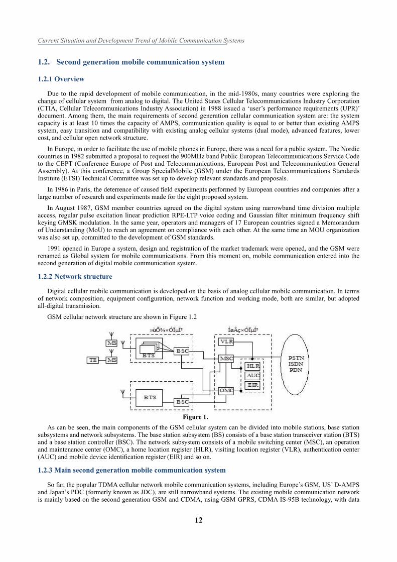
GSM cellular network structure are shown in Figure 1.2
Figure 1.
As can be seen, the main components of the GSM cellular system can be divided into mobile stations, base station subsystems and network subsystems. The base station subsystem (BS) consists of a base station transceiver station (BTS) and a base station controller (BSC). The network subsystem consists of a mobile switching center (MSC), an operation and maintenance center (OMC), a home location register (HLR), visiting location register (VLR), authentication center (AUC) and mobile device identifi cation register (EIR) and so on.
1.2.3 Main second generation mobile communication system
So far, the popular TDMA cellular network mobile communication systems, including Europe’s GSM, US’ D-AMPS and Japan’s PDC (formerly known as JDC), are still narrowband systems. The existing mobile communication network is mainly based on the second generation GSM and CDMA, using GSM GPRS, CDMA IS-95B technology, with data
Lin J, et al.
13
providing capacity of up to 115.2kbit / s. The global mobile communication system (GSM) using enhanced data Rate (EDGE) technology with the rate of up to 384kbit / s.
The three TDMA cellular mobile communication system GSM, D-AMPS, and PDC due to the development background, time and requirements are not the same, so the technical performance and service functions are also different. For ease of analysis and comparison, Table 1.2 lists the main parameters of the three TDMA cellular communication systems.
Europe
GSM
United StatesD-AMPS
Japan
JDC
Multiple access modeTDMA/FDMA
TDMA/FDMA
TDMA/FDMA
Frequency /MHz mobile station Base stations
890~ 915 824~ 849 940~ 956/1429~ 1453
935~ 960 869~ 894 810~ 826/1477~ 1501
Carrier frequency interval /kHz 200 30 25
Number of slots / carrier frequency 8/16 3/6 3/6
Modulation method GMSK π/4-QPSK π/4-QPSK
Speech Rate after Error Correction(kb/s) 22.8 13 11
Channel rate(kb/s) 270.833 48.6 42
TDMA frame length /ms 4.615 40 20
Interleaving span /ms 40 27 27
1.3. Third generation mobile communication system
1.3.1 Overview
A farewell to the ‘big bricks’, mobile communications entered the second generation, the information content are still dry, making great demands as a driving force for the IMT-2000 debut.
Global communications service, and also the network technology, computer technology, microelectronics technology and other basic research have rapid development. The rapid development of the second generation of mobile communication narrowband constraints has become a bottleneck restricting its development, people for multimedia broadband access are increasing day by day. In order to meet this strong demand, the ITU began its research on the third generation of mobile communication systems (3G).
The third generation mobile communication system IMT-2000 (International Mobile Telecommunications 2000), is a further evolution in the second generation of mobile communication technology based on the broadband CDMA-based technology, and can provide voice and data services. This was the future of mobile communication systems, which had the ability to solve the main drawbacks fi rst and second generation of mobile communication system.
As we all know, in the second generation of digital mobile communication system, the communication standards caused unequal development, although greatly promoted the pre-local mobile communication development, but also created more mandatory constraints of the later global mobile communication to further develop. This includes the use of diff erent frequency bands, a variety of communication standards coexist, making the ‘global’ roaming service diffi cult to truly achieve, while the existing bandwidth technology cannot meet the information content and data types growing needs. The huge hardware and software resources invested by the second generation mobile communication and the huge market share that has been occupied determine that the third generation mobile communication can only be smoothly compatible with the second generation mobile communication system. This also makes the third generation mobile development of communication standards complex and diffi cult to determine.
1.3.2 Advantages of third generation mobile communication
Compared with the previous two generations of systems, the third generation system has greater capacity, better communication quality, and higher band utilization. These features provide for high-speed and low-speed mobile users voice, data, video, multimedia and other services. Users can seamlessly roam around the world.
Current Situation and Development Trend of Mobile Communication Systems
14
2. The status of the third generation mobile communication system
2.1. Application principle
2.1.1 Requirements for third generation mobile communications
Based on the IMT-2000 / FPLMTS evaluation criteria proposed by ITU in 1995, a more detailed request was made for the third generation cellular mobile communication system.
The main goal of the IMT-2000 is to integrate all the networks, including satellite networks, into a ‘unifi ed system’ that can function as a substitute for many networks, providing broadband services and seamless global coverage, including:
(1) to provide multimedia services that second generation system cannot provide (rate can be up to 2mbps);
(2) to provide global seamless coverage and roaming;
(3) to adapt to a variety of service environment, including satellite mobile, cordless, cellular, data network, pstn, ip;
(4) high spectral effi ciency, large capacity;
(5) light mobile terminal, low cost and multi-frequency / multi-mode function;
(6) the quality of service is equivalent to the level of fi xed network, high security performance, with reasonable fees;
(7) with a single communication number, frequency and radio resource management, system confi guration, service provision and fl exible network structure can be combined using the intelligent network;
(8) The system confi guration can take full advantage of the second generation of equipment and facilities, a smooth upgrade is possible to support the previous system evolution and transition after the completion of the system.
2.1.2 Network structure of third generation mobile communication system
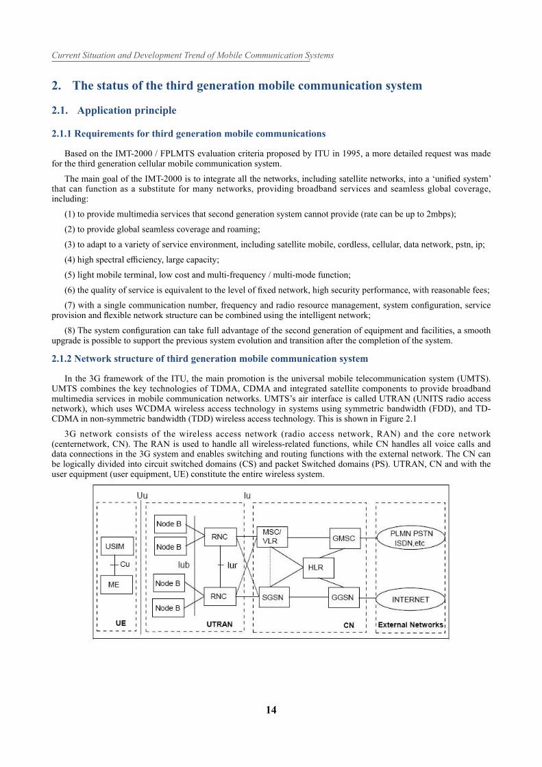
In the 3G framework of the ITU, the main promotion is the universal mobile telecommunication system (UMTS). UMTS combines the key technologies of TDMA, CDMA and integrated satellite components to provide broadband multimedia services in mobile communication networks. UMTS’s air interface is called UTRAN (UNITS radio access network), which uses WCDMA wireless access technology in systems using symmetric bandwidth (FDD), and TD-CDMA in non-symmetric bandwidth (TDD) wireless access technology. This is shown in Figure 2.1
3G network consists of the wireless access network (radio access network, RAN) and the core network (centernetwork, CN). The RAN is used to handle all wireless-related functions, while CN handles all voice calls and data connections in the 3G system and enables switching and routing functions with the external network. The CN can be logically divided into circuit switched domains (CS) and packet Switched domains (PS). UTRAN, CN and with the user equipment (user equipment, UE) constitute the entire wireless system.
Lin J, et al.
15
2.2. Technical support
2.2.1 The main technical problems faced
3G system does show people good communication prospects, but the realization of these beautiful prospects to overcome the 3G system is facing the technical problems. Some of these problems are inherent in cellular mobile communications, and some are unique to 3G systems. Only by understanding these issues can we understand the signifi cance of the various key technologies developed to solve these problems.
1, Multipath fading: This problem exists in all mobile communication systems. The radio waves in the propagation will be refracted, reflected and scattered, resulting in multiple propagation paths. When the signal of different path arrives at the receiver, the amplitude and phase fluctuation of the received signal cause serious fading due to the position, direction and polarization of the antenna. In order to ensure the quality of communication, the signal power has to be increased, which directly aff ects the system capacity.
2, The delay expansion: diff erent path signals have diff erent propagation delay. When extended beyond the detection pulse width of 10%, the inter-symbol interference is obvious, thus limiting the data rate of mobile communications.
3, Multiple access interference: As the 3G system using code division multiple access (CDMA) technology, that is, using diff erent spread code to distinguish between users, requires users of the spread code has a strong autocorrelation and weak mutual correlation. But in fact the mutual interference between users can not completely disappear, so the CDMA system is interference limited, that is from the community and adjacent cell users are the main factors to determine the interference of the system capacity and its performance. Multiple access interference is unique to 3G system.
4, Far and near eff ect: If the mobile stations sending signals in the same power, the base station received from mobile station nearest to send the signal power will be greater than the further mobile station. Far and near eff ect refers to the recent high-power signal generated a strong interference on the distant low-power signal. It is also a class of multiple access interference, but in the 3G system, this multi-site interference is very prominent on performance.
5, The system: At present, the first generation and second generation system has been widely used, so from the perspective of resource utilization, 3G systems must be compatible with the previous two generations of systems, and smooth transition to the fourth generation mobile communication systems in the future, and matching the highest goal of personal communication systems. But at present, the fi rst generation and second generation systems the system varied due to a wide range of emerging standards. So, how to make the 3G system plays a role for ensuring a good future, currently an urgent problem to be solved.
2.2.2 Key Technologies
In order to solve the main problems that 3G systems face, scholars from all over the world have carried out extensive and in-depth research, which developed and innovated many key technologies. Some of these technologies have been adopted by the 3G system, and some are still under further study.
1, Multiple access technology. The multiple access technology referred here includes two aspects: one of them refers to the study of the address code in the CDMA system, the second is the further study of the various multiple access protocols. Because the 3G system uses code division multiple access technology, so the choice of spread code is essential. IS-95 system uses 64-bit Walsh function as a spread code, the performance of the forward channel can be guaranteed, but the reverse channel performance is not satisfactory. At present, scholars have extensively studied the orthogonally variable frequency factor (OVSF), hoping to solve the problem of generating method, available number and multiplexing, so that it can be put into use as soon as possible.
In addition, CDMA / PRMA multiple access protocol has also been given great attention, it can be seen as the protocol expansion of traditional packet reservation multiple access (PRMA). PRMA is based on time division multiple access frame structure, each user has a certain probability of competition for idle time slot, only in accordance with real information output, with. The results show that the CDMA / PRMA protocol can improve the capacity of the system by 68% ~ 84% compared with the random access CDMA in the cellular environment and only voice.
2, Channel coding. While spread spectrum technology is advantageous in overcoming multipath fading to provide high quality transmission channels, the spread spectrum system has potential for very low spectral effi ciency. Therefore, the system must use channel coding technology to further improve the communication quality. At present, to further overcome the fading eff ect, the forward channel error correction coding and interleaving technology are used. Coding and interleaving are heavily dependent on the characteristics of the channel and the needs of the service. Not only the service channel and control channel using diff erent coding and interleaving technology, but also for the same channel of different services different coding and interleaving technology are also been used. At present, more study are
Current Situation and Development Trend of Mobile Communication Systems
16
done on packet coding, convolutional code and trellis code modulation. In the three coding techniques, M-ary radio frequency RF modulation combined with grid error correction coding scheme can provide greater bandwidth effi ciency, but according to the current error correction coding technology development trend, combined with packet code and convolutional cascade code technology, such as parallel concatenation code, will be more attractive.
3, Power control. Power control technology is an eff ective way to solve the far and near eff ects. In the uplink, in order to overcome the wide range of broadband CDMA system, dynamic range of 80dB power control is required. The uplink power control mode is divided into two types: ring and closed loop. The closed loop power control includes inner loop control and outer loop control. The open loop power control is mainly used to overcome the distance attenuation, and the closed loop power control is used to overcome the fading generated by the Doppler frequency, thus ensuring that all mobile station signals received by the base station have the same power. In the downlink, in order to achieve fast and adaptive power control algorithm, power control sub-channel is included to achieve the forward closed-loop power control.
4, Smart antenna. Smart antenna is also called adaptive array antenna, which composed of three parts: antenna array, beamforming network, and beam forming algorithm. It adjusts the weighted amplitude and phase of each array signal by satisfying some of the algorithms of the criterion by adjusting the pattern of the antenna array to achieve the purpose of enhancing the required signal and suppressing the interference signal. Smart antenna can also be used to explain the concept of space division multiplexing (SDMA), that is, the diff erence between the direction of the signal incident used to distinguish frequency from the same time slot signal, so as to achieve the expansion of the purpose of communication system capacity. Smart antenna technology has become increasingly perfected. China Telecom Science Research Institute Xinwei company has launched a smart antenna with a synchronous CDMA system, the United States Metawave communications company’s smart antenna has also been put on the market.
5, Multi-user detection. Conventional detectors in a communication system are single-user detectors that treat the signals of the desired user as useful signals and treat the signals of other users as interfering signals. But from the information theory point of view, CDMA system is a multi-input, multi-output channel. So, the single-user detector cannot take full advantage of the channel capacity. The basic idea of multi-user detection is to treat all users’ signals as useful signals, rather than interfering signals, so that information such as user code, amplitude, timing and delay of each user’s signal can be fully utilized, thereby signifi cantly reducing multiple access interference. At present, there are two basic methods to achieve multi-user detection: First, linear detection method, its basic idea is using linear transformation to eliminate the correlation between diff erent users, so that each user’s detected signals are related signals of own. The second method is a subtractive interference canceller which subtracts the locally estimated multiple access interference from other users in the signal fed to the matched fi lter input, thereby eliminating multiple access interference.
6, Switching technology. Since the mobile communication system uses a cellular structure, it is necessary for the mobile station to perform handover when the mobile station passing through across divided spaces, that is, the transfer of the air interface to the base station to the base station, the base station to the network entrance, and corresponding transfer of the network entrance to the switching center. In the first and second generation mobile communication systems hard switching mode are used, hard switching makes communication easy to be interrupted. 3G system will use the same carrier frequency of the cell to achieve a soft handover, that is, mobile users in crossing the two base stations can be connected at the same time, the corresponding change in the spread code connects before switching, thus greatly improving the switching quality of the call. But the specifi c implementation of soft switching methods and steps are still studied. In addition, the switching between the diff erent carriers of the carrier are still in hard switching, so there are many problems switching technology needs to be resolved.
7, The channel structure and the upper protocol signaling. 3G system users are huge, and to achieve global roaming, then the management of various resources must be very complex and huge, which requires a reasonable channel structure a variety of rich and perfect protocol signaling. 3G system’s wireless air interface will use hierarchical structure and protocols, these protocols include user platform, control platform and control platform transmission signaling. This includes call control, mobility management, wireless carrier control, radio resource control, and so on.
8, Software radio. The software radio is a revolution in the wireless transmission system, which is called ‘the radio world of personal computers’. The core idea of software radio is to use A / D and D / A converters as close to the antenna as possible, and to defi ne the functions of the radio as much as possible through software on a common hardware platform. This system uses a unifi ed platform, through the software to generate GSM, IS-95, IS-665, IMT2000 and other diff erent systems of the terminal, and can adapt to the future development of technology. It is compatible with the underlying transport model of the Broadband Integrated Services Network, which is adapted to the future services and is consistent with the development of software-defined telecom information networks. Software is another leap in wireless transmission systems from analog to digital. In the civil sector, Aircom has launched GSM-based station system. In the military, the United States has launched a ‘easy to talk’ demonstration system. The system can produce 13 kinds of waveforms in the fi rst stage, the second stage can produce 27 kinds of waveforms, which work in 30 kinds of networks and with 13 kinds of encryption system. China 863-317 also carried out research in this theme. Perhaps only the full realization of software radio, human beings can achieve the wishes of personal communication.
Lin J, et al.
17
3. Comparison of existing third generation communication systems
3.1. WCDMA system
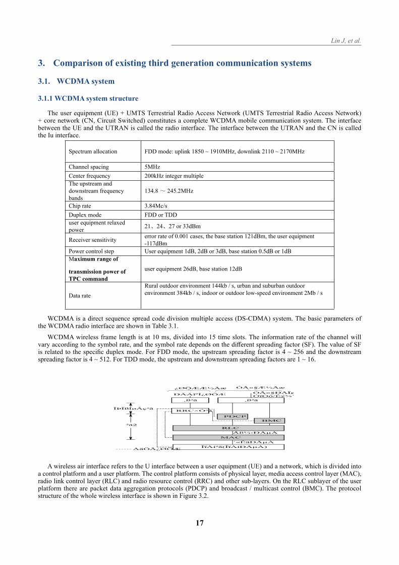
3.1.1 WCDMA system structure
The user equipment (UE) + UMTS Terrestrial Radio Access Network (UMTS Terrestrial Radio Access Network) + core network (CN, Circuit Switched) constitutes a complete WCDMA mobile communication system. The interface between the UE and the UTRAN is called the radio interface. The interface between the UTRAN and the CN is called the Iu interface.
Spectrum allocation FDD mode: uplink 1850 ~ 1910MHz, downlink 2110 ~ 2170MHz
Channel spacing 5MHz
Center frequency 200kHz integer multiple
The upstream and downstream frequency bands
134.8~ 245.2MHz
Chip rate 3.84Mc/s
Duplex mode FDD or TDD
user equipment relaxed power
21、24、27 or 33dBm
Receiver sensitivityerror rate of 0.001 cases, the base station 121dBm, the user equipment -117dBm
Power control step User equipment 1dB, 2dB or 3dB, base station 0.5dB or 1dB
Maximum range of
transmission power of TPC command
user equipment 26dB, base station 12dB
Data rate
Rural outdoor environment 144kb / s, urban and suburban outdoor environment 384kb / s, indoor or outdoor low-speed environment 2Mb / s
WCDMA is a direct sequence spread code division multiple access (DS-CDMA) system. The basic parameters of the WCDMA radio interface are shown in Table 3.1.
WCDMA wireless frame length is at 10 ms, divided into 15 time slots. The information rate of the channel will vary according to the symbol rate, and the symbol rate depends on the diff erent spreading factor (SF). The value of SF is related to the specifi c duplex mode. For FDD mode, the upstream spreading factor is 4 ~ 256 and the downstream spreading factor is 4 ~ 512. For TDD mode, the upstream and downstream spreading factors are 1 ~ 16.
A wireless air interface refers to the U interface between a user equipment (UE) and a network, which is divided into a control platform and a user platform. The control platform consists of physical layer, media access control layer (MAC), radio link control layer (RLC) and radio resource control (RRC) and other sub-layers. On the RLC sublayer of the user platform there are packet data aggregation protocols (PDCP) and broadcast / multicast control (BMC). The protocol structure of the whole wireless interface is shown in Figure 3.2.
Current Situation and Development Trend of Mobile Communication Systems
18
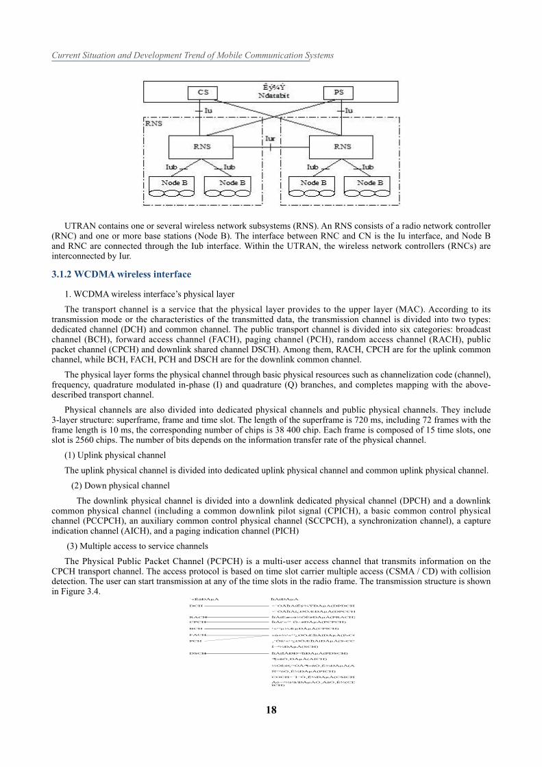
UTRAN contains one or several wireless network subsystems (RNS). An RNS consists of a radio network controller (RNC) and one or more base stations (Node B). The interface between RNC and CN is the Iu interface, and Node B and RNC are connected through the Iub interface. Within the UTRAN, the wireless network controllers (RNCs) are interconnected by Iur.
3.1.2 WCDMA wireless interface
1. WCDMA wireless interface’s physical layer
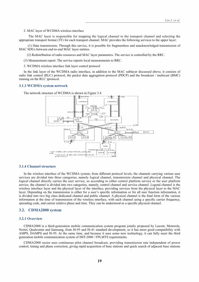
The transport channel is a service that the physical layer provides to the upper layer (MAC). According to its transmission mode or the characteristics of the transmitted data, the transmission channel is divided into two types: dedicated channel (DCH) and common channel. The public transport channel is divided into six categories: broadcast channel (BCH), forward access channel (FACH), paging channel (PCH), random access channel (RACH), public packet channel (CPCH) and downlink shared channel DSCH). Among them, RACH, CPCH are for the uplink common channel, while BCH, FACH, PCH and DSCH are for the downlink common channel.
The physical layer forms the physical channel through basic physical resources such as channelization code (channel), frequency, quadrature modulated in-phase (I) and quadrature (Q) branches, and completes mapping with the above-described transport channel.
Physical channels are also divided into dedicated physical channels and public physical channels. They include 3-layer structure: superframe, frame and time slot. The length of the superframe is 720 ms, including 72 frames with the frame length is 10 ms, the corresponding number of chips is 38 400 chip. Each frame is composed of 15 time slots, one slot is 2560 chips. The number of bits depends on the information transfer rate of the physical channel.
(1) Uplink physical channel
The uplink physical channel is divided into dedicated uplink physical channel and common uplink physical channel.
(2) Down physical channel
The downlink physical channel is divided into a downlink dedicated physical channel (DPCH) and a downlink common physical channel (including a common downlink pilot signal (CPICH), a basic common control physical channel (PCCPCH), an auxiliary common control physical channel (SCCPCH), a synchronization channel), a capture indication channel (AICH), and a paging indication channel (PICH)
(3) Multiple access to service channels
The Physical Public Packet Channel (PCPCH) is a multi-user access channel that transmits information on the CPCH transport channel. The access protocol is based on time slot carrier multiple access (CSMA / CD) with collision detection. The user can start transmission at any of the time slots in the radio frame. The transmission structure is shown in Figure 3.4.
Lin J, et al.
19
2. MAC layer of WCDMA wireless interface
The MAC layer is responsible for mapping the logical channel to the transport channel and selecting the appropriate transport format (TF) for each transport channel. MAC provides the following services to the upper layer:
(1) Data transmission. Through this service, it is possible for fragmentless and unacknowledged transmission of MAC SDUs between end-to-end MAC layer entities.
(2) Redistribution of radio resources and MAC layer parameters. The service is controlled by the RRC.
(3) Measurement report. The service reports local measurements to RRC.
3. WCDMA wireless interface link layer control protocol
In the link layer of the WCDMA radio interface, in addition to the MAC sublayer discussed above, it consists of radio link control (RLC) protocol, the packet data aggregation protocol (PDCP) and the broadcast / multicast (BMC) running on the RLC )protocol.
3.1.3 WCDMA system network
The network structure of WCDMA is shown in Figure 3.4
3.1.4 Channel structure
In the wireless interface of the WCDMA system, from diff erent protocol levels, the channels carrying various user services are divided into three categories, namely logical channel, transmission channel and physical channel. The logical channel directly carries the user service, so according to either control platform service or the user platform service, the channel is divided into two categories, namely, control channel and service channel. Legend channel is the wireless interface layer and the physical layer of the interface, providing services from the physical layer to the MAC layer. Depending on the transmission is either for a user’s specifi c information or for all user function information, it is divided into two big class dedicated channel and public channel. A physical channel is the fi nal form of the various information at the time of transmission of the wireless interface, with each channel using a specifi c carrier frequency, spreading code, and carrier relative phase and time. They can be understood as a specifi c physical channel.
3.2. CDMA2000 system
3.2.1 Overview
CDMA2000 is a third-generation mobile communication system program jointly proposed by Lucent, Motorola, Nortel, Qualcomm and Samsung, from IS-95 and IS-41 standard development, so it has more good compatibility with AMPS, DAMPS and IS-95. At the same time, and because it uses some new technology, it can fully meet the third generation mobile communication system of IMT-2000 / FPLMTS requirements.
CDMA2000 sector uses continuous pilot channel broadcast, providing transmission rate independent of power control, timing and phase correction, giving rapid acquisition of base stations and quick search of adjacent base stations
Current Situation and Development Trend of Mobile Communication Systems
20
with small complexity. The same short code structure as IS-95 adding the Walsh function to minimize the average transmit power of the forward link between quadrature, high-speed (800 bit / s) forward link power control.
Modulation mode adopts multi-carrier mode and direct expansion mode. These two methods have the same information transfer rate and implementation complexity. The multi-carrier CDMA link has three 1.25 MHz CDMA carriers in the 5 MHz bandwidth and 10 1.25 MHz carriers at 10 MHz bandwidth. The multi-carrier CDMA forward link signal is orthogonal to the IS-95 forward link signal, and the encoded information symbols are transmitted on multiple CDMA carriers at the same time. The resulting frequency domain diversity is equivalent to extending the signal to the entire bandwidth. The pilot signal can be shared when the IS-95 overlaps the multi-carrier traffi c channel and allows forward link capacity to be dynamically shared between IS-95 and broadband users in the same frequency band, continuing to support low cost / low power IS- 95 mobile phones for voice and low-speed data services.
Direct spread spectrum spread rate is 3.6864 Mchip / s, using 256-bit Walsh code. The length of the Walsh code may vary depending on the wireless environment and data rate, using a 256-bit Walsh code at a channel rate of 9.6 kbit / s or 14.4 kbit / s. Fast-moving users may limit the Walsh code length to 16 Bit. Users in the wireless channel situation is better, 4-bit Walsh code can be used to achieve the highest data rate.
3.2.2 Principles of system composition
CDMA2000 system components module is divided into three parts: user equipment, base stations, and core network.
1. Interface and protocol
In the grouping of network functional entities, the main network interface reference point can be divided into several main parts.
(1) Interface between the wireless access network and the core network reference point
The interface reference point includes the A interface reference point between the BSC and the MSC, and the Aquater interface reference point between the PGF and the PDSN.
(2) Interface reference point in the core network area
The interface reference point includes most of the interface reference points in the wireless network, including the interfaces between MSC, HLR, VLR, AC, MC and SME, and the interface between these functional entities and the wireless intelligent network and location service function entities.
(3) Interface reference point in the core network packet domain
The interface reference point corresponds to the Pi reference point in the wireless network reference model, including the interface between PDSN, AAA and HA.
(4) Interface reference point for mobile network connection to external network
The interface part interface completes the connection between the mobile network and the external PSTN, ISDN, PDN and so on, and supports the circuit type service and the packet type service, including the Ai interface of the circuit domain core network and the external PSTN, the circuit domain core network and the external ISDN network Di Interface, and the packet interface between the core network and the external data network.
3.2.3 Diversity technology
Diversity technology is a basic technology in wireless communication system against fading and improving transmission reliability. Diversity techniques can be implemented in the time domain, frequency domain, or airspace. Their basic principles are the same: multiple signals carrying the same information are sent over multiple paths, and multiple independent fading copies of the data symbols can be obtained at the receiving end, thus achieving more reliable detection.
The criteria for merging these independent fading replicas are generally three: selective merging, equal gain merging, and maximum ratio merging. Selective merging’s criterion is choosing from copy with maximum signal-to-noise ratio from the multiple copies as an output. Equal gain merging and maximum ratio merging does not calculate of the signal to noise ratio, simply add them in phase. In the maximum ratio merging, the weighting factor for each replica is proportional to the respective received signal to noise ratio.
There are many ways to get diversity. Time diversity can be obtained by coding and interleaving: the information is encoded and then interleaved into diff erent coherent periods, so that diff erent codewords experience independent fading. Similarly, if the channel is selective in frequency, then the frequency diversity can be obtained. In multi-transmitting or receiving antenna systems where the antenna spacing is large enough, diversity can be obtained through space. In a
Lin J, et al.
21
cellular network, two adjacent base stations can receive signals from the same mobile station, so that macroblocks can be obtained.
3.3. TD-SCDMA system
3.3.1 Composition principle
TD-SCDMA system is developed by China Telecom Research Institute of Ministry of Information Industry. It adopts TDMA and TDD, Software Radio, smart antenna, and synchronous CDMA technology. It is divided into three parts: user equipment, base station, and core network.
The TD-SCDMA system’s multiple access scheme is DS-CDMA with a chip rate of 1.28 Mc / s and a spread bandwidth of approximately 1.6 MHz using the TDD mode of operation. The information of its downstream (forward link) and upstream (reverse link) is transmitted on diff erent timeslots of the same carrier frequency. In the TD-SCDMA system, the multiple access mode other than DS-CDMA features, at the same time possess the characteristics of TDMA. Therefore, TD-SCDMA access mode can also be expressed as TDMA / CDMA.
The physical layer provides data transmission services to the upper layers, which are accessed through the transport channel. To provide data transfer services, the physical layer needs to complete the following functions:
Transmission channel error detection and reporting
FEC encoding and decoding of transmission channels
Multiplexing / demultiplexing of transport channels and coded composite transport channels
Coding the combined transport channel to the physical channel
Modulation / spreading and demodulation / despreading of physical channels
Frequency and clock (chip, bit, time slot and subframe) synchronization
Power control
Power weighting and consolidation of physical channels
RF processing
Rate matching
Wireless characteristic measurement, including FER, SIR, interference power and so on
Uplink synchronous control
Uplink and downstream beamforming (smart antennas)
UE positioning (smart antenna)
3.3.2 Characteristics of TD-SCDMA systems
TD-SCDMA and other third-generation mobile communication system standard has a more obvious advantage, mainly in the following aspects below:
(1) Spectrum fl exibility and the ability to support cellular networks
TD-SCDMA uses TDD mode, which only need 1.6 MHz (single carrier) of the minimum bandwidth. It’s frequency gives fl exible arrangements, which pairing of frequencies are not required. Any pieces of the band can be used, hence a better solution for the current frequency resource constraints.
(2) High spectral effi ciency
TD-SCDMA spectrum utilization is high with high anti-interference ability. The system capacity is large, suitable for large and medium-sized population in the transmission of symmetrical and asymmetric service, especially for mobile Internet service.
(3) Applicable to a variety of use of the environment
TD-SCDMA system fully meets the requirements of ITU, which made it applicable to a variety of environments.
3.3.3 Key Features and Key Technologies of TD-SCDMA
1. System code
Current Situation and Development Trend of Mobile Communication Systems
22
TD-SCDMA system will work in ITU-defi ned frequency band with each carrier bandwidth of 1.6MHz, after the spread the chip rate is about 1.354 chips / s, with 200kHz as the reserved frequency synthesizer step. Each RF code channel consists of 10 time slots, the average length of the slot after removal of the guard time slot is 478us, and each time slot contains 16 Walsh distinctions, which are used by direct spreading technology to share the same RF channel. The physical channel determined by each slot and code channel can be allocated as a resource unit to any user. The protection slots of the upper and lower services can guarantee a communication range of 20 km between the mobile phone and the base station. Between each slot unit, there are 8 chip protection slots to prevent the overlap between diff erent time slots. Code channel through dynamic allocation, can support up to 2048kbit / s of data services, but at this time there must be at least one channel for uplink access.
2. Synchronous code division multiple access technology
This is a very important technology in TD-SCDMA technology, which means that all the camoufl age of the user is synchronized when it arrives at the base station. Due to the synchronization orthogonality between pseudo-random codes, this system can eff ectively eliminate intersymbol interference and expand the system capacity. For now, TD-SCDMA in future capacity of similar system will be at least four times the other two CDMA standards.
3. Smart antenna
TD-SCDMA smart antenna technology has long been completed, and is the recommended wireless technology in the use of this communication system. The smart antenna consists of a ring antenna array and the corresponding transmit and receive unit, which are controlled by corresponding algorithm. Unlike a conventional omnidirectional antenna that produces only one beam, the smart antenna system can give multiple beamforms, each lobe corresponds to a particular handset user, and the beam can also track the user dynamically.
In terms of reception, this technology allows for spatial selection reception, which not only increases the reception sensitivity, but also minimizes the total code channel interference from mobile phones from diff erent locations, hence increasing the overall capacity of the network. This antenna uses two-way beam shaping, eliminating interference while increasing the capacity of the CDMA system, and reduce the base station transmit power requirements, even if a single antenna unit is damaged, will not be a signifi cant impact to the system.
4. Relay switch
Unlike the other two technologies used in the hard switching and soft switching, TD-SCDM uses a new switching technology, named ‘relay switch.’
The technique of combining the synchronization code division multiple access and the smart antenna is when the relay is switched. How to locate mobile users in mobile systems has always been a topic of concern to users. The TD-SCDM system utilizes the well-being of the chip cycle in antenna array and synchronous code division multiple access technology to obtain the user’s location. Then the base station according to the surrounding airborne conditions and signal quality, the phone switched to base station with more excellent signal. In this way, this technology can also dynamically allocate the capacity of the entire base station network, and can also switch between diff erent systems.
5. Software radio
In the TD-SCDMA system, DSP (digital signal processing technology) will replace the conventional mode, achieve wireless transmission which originally through the RF, baseband analog circuits and ASIC. These features include intelligent RF beamforming, in-board RF correction, carrier recovery, and timing adjustments.
The main advantage of using software wireless point technology is that the software can complete the function of hardware, to reduce the network burden. In terms of repeatability and accuracy, the error rate is small and fault tolerance is high. The hardware approach is so easy to age and has a greater sensitivity to the environment. Software costs less to achieve complex hardware functions, reducing the total investment.
6. Spectrum utilization
Spectrum utilization is one of the major requirements of ITU for 3G systems. In the current 2G system, CDMA IS-95 technology has the highest spectrum utilization.
Because CDMA itself is self-interference system, if then problem of pseudo-random code between the inter-code interference and distance is solved, it will greatly enhance the system. TD-SCDMA technology through the spread code between the orthogonality combined with smart antenna technology, can provide the capacity exceeding 4-5 times of CDMA-IS95 system. This have been confi rmed through the SCDMA technology wireless local loop scene tests.
7. Multimedia service
TD-SCDMA standard communication system, in addition to providing basic voice communications services, will also provide digital and packet video services. Although the model is used by all users to share the same frequency
Lin J, et al.
23
resources, but with a smart antenna, it is possible to dynamically allocate power according to the level of service quality and requirements for diff erent users, and to ensure that interference does not exceed the upper limit.
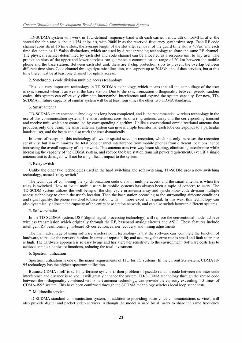
3.4. Comparison of three systems
Table 3.4 compares the main technical performance of the three mainstream standards for WCDMA, TD-SCDMA and CDMA 2000. Among them, only TD-SCDMA uses advanced technology such as smart antenna, joint detection and synchronous CDMA, so it has obvious advantages in terms of system capacity, spectrum utilization and anti-jamming capability.
WCDMA TD-SCDMA CDMA2000
Carrier frequency interval /MHz
5 1.6 1.25
Chip rate (Mc/s) 3.84 1.28 1.2288
Frame length /ms 1010(divided into two subframes)
20
Base station synchronization
Required RequiredRequired, the typical method is GPS
Power control fast power control: up, down 1500Hz 0~ 200Hz
reverse: 800Hz
Forward: slow, fast power control
Downlink transmit diversity
SupportedSupported Supported
Frequency switchingSupported, available in compression mode
Supported, available free
Time slot for support
Supported
Detection mode coherent demodulation joint detection coherent demodulation
Channel estimation common pilotDwPCH, UpPCH,
Intermediate codeforward, reverse pilot
4. The Future of Mobile Communication Systems
4.1. Fourth generation mobile communication system (4G)
4.1.1 Introduction to 4G
In the 21st century, the rapid development of mobile communication technology and market, under the combined action of new technology and market demand, the future mobile communication technology will show the following trends: network service are more data-oriented, grouped and gradually forming mobile internet; network technology digitalization, broadband automation, and miniaturization; Application on higher frequency band and the eff ective use of frequency; Mobile network integration, globalization, and personalization; A variety of network integration; High speed, high quality, and low cost. This is the direction and goal of the fourth generation (4G) mobile communication technology development.
The concept of the fourth generation of mobile communication technology can be known as broadband access and distribution network, with asymmetric data transmission capacity of more than 2Mbit / s. It includes broadband wireless fixed access, broadband wireless LAN, mobile broadband systems and interactive broadcast networks. The fourth generation mobile communication standard has more features than the third generation standard. The fourth generation of mobile communications can provide wireless services in fi xed platforms, wireless platforms and networks across different frequency bands. Broadband access to the Internet (including satellite communications and stratospheric communications) can provide location timing, data collection, remote control and other integrated functions. In addition, the fourth generation mobile communication system integrates multi-functional broadband mobile communication system, which makes the system a broadband access IP system.
4.1.2 The main features of 4G
4G communications currently under development and will have the following characteristics:
First, faster communication.
Current Situation and Development Trend of Mobile Communication Systems
24
Second, wider network spectrum.
Third, a variety of service integration.
Fourth, higher intelligent performance.
Fifth, more smooth compatibility .
Six, achieve higher quality in multimedia communications.
Seven, cheaper communication costs.
4.1.3 Key Technologies in 4G Mobile Communication
First, positioning technology.
Location refers to the measurement method and calculation method of the mobile terminal position.
Second, switching technology
Switching technology is suitable for mobile terminals in different mobile cells, between different frequencies of communication or signal to reduce channel selection, and others.
Third, software radio technology
In the 4G mobile communication system, the software will become very complicated.
Fourth, smart antenna technology
Smart antenna with intelligent interference suppression, automatic tracking and digital beam adjustment and other intelligent functions, will further meet the data center and mobile IP network performance requirements.
5, Interactive interference suppression and multi-user identifi cation
The interactive interference suppression and multiuser identifi cation techniques should be part of 4G, which interacts with interference and introduced into the base station and the mobile telephone system to eliminate the interference of unnecessary neighboring and co-channel users, ensuring receiver’s high quality receive signal.
6, The new modulation and signal transmission technology
High-speed mobile communications in the high frequency range will face severe frequency-selective fading.
5. Conclusion
On the current situation, 3G technology is not fully matured, has not been widely used, but people have begun research and outlook in 4G. The development of the third generation mobile communication technology will be a rare opportunity for the development of China’s telecommunications industry. For various reasons, China has not really formed its own national industry in the development of the first generation and second generation mobile communication. The third generation of mobile communication standards is not perfect, there are many yet to improve the technology and norms, which is very favorable for the market late comers. At present, China has become one of the fastest growing mobile communications countries, and in the future will be the world’s largest mobile communications market. We should seize the opportunity to strive for the development of technology, for the establishment in the communications industry, reaching the development of a leading country in the future communications service.
References
1. Li Jiedong, Guo Liyun, Wu Guo Yang. Mobile Communications [M]. Xi’an: Xi’an University of Electronic Science and Technology Press, 2006.12. 220 ~ 383
2. Li Zhiqun. Communication electronic circuit [M]. Beijing: Tsinghua University Press, 2011.4. 9 ~ 493. Li Yongzhong, Xu Jing. Modern Communication Principles, Technology and Simulation [M]. Xi’an: Xi’an University of
Electronic Science and Technology Press, 2010.6. 419 ~ 4404. Cai Yueming, Wu Qihui, Tian Hua, Gao Zhan. Modern mobile communication [M]. Beijing: Mechanical Industry Press .2007.8
153 ~ 2495. Sipang Gang, Gao Weidong, Peng Tao .TD-SCDMA wireless network planning optimization and wireless resource
management [M]. Beijing: People’s Posts and Telecommunications Press, 2007.6 8 ~ 366. Kang Guixia, Tian Hui, Zhu Yutao, Du Juan. CDMA2000 1x wireless network technology [M]. Beijing: People’s Posts and
Telecommunications Press, 2007.12 18 ~ 967. Xie Xianzhong, et al. TDD-based fourth generation mobile communication technology [M]. Beijing: Electronic Industry Press,
2005.
Lin J, et al.
25
8. Zhang Ping. The third generation of cellular mobile communication system: WCDMA [M]. Beijing: Beijing University of Posts and Telecommunications Press, 2001.1
9. Xie Xianzhong. TD-SCDMA third generation mobile communication technology and implementation. Beijing: People’s Posts and Telecommunications Press, 2004.6
10. Zhang Chuanfu, Peng Can, et al. CDMA mobile communication network planning and design and optimization. Beijing: People’s Posts and Telecommunications Press, 2006.3


![Mobile Technology Trend [Android]](https://static.fdocuments.in/doc/165x107/554d2368b4c905ab268b4aac/mobile-technology-trend-android.jpg)