Investigation of the effect of ceramic coatings on rocket thrust ...

1
Current activities in the field of ceramic based rocket engines M. Ortelt*, F. Breede +, A. Herbertz*, D. Koch#, †H. Hald
German Aerospace Center (DLR), Stuttgart 70569, Germany
Abstract
In the last two decades DLR spent a lot of effort in the development of ceramic rocket thrust chambers. A first system evaluation in the nineties led directly to the operative range of transpiration cooled inner combustion chamber liners because of the natural inherent micro-porosity of Ceramic Matrix Composites (CMCs). CMCs as high temperature resistant structural materials represent a relatively young class of materials, which shows high future potential for high temperature and in parallel structurally high performance applications. A variety of basic empirical and numerical investigations of this technology has been conducted. The field of pure material research, system analysis and experimental works at relevant test benches for rocket engines at the DLR location of Lampoldshausen stood in the major focal point. Especially the P8 European Research and Technology Test Facility as well as the relatively new P6.1 Technology Test Bench are good platforms to demonstrate such interesting technology approaches. At these two test benches a lot of technology results and also development perspectives could be obtained. The current development status shows high application potential of transpiration cooled CMC rocket engines, related to newest material knowledge in combination with a highly efficient operating of cryogenic rocket thrust chambers. Suitable structure approaches of the fundamental thrust chamber components, in particular the subsonic ceramic combustion chamber section, a new injector design based on porous oxidic CMC material and a CMC supersonic nozzle extension are very promising concerning the demonstration of complete ceramic thrust chamber assemblies under cryogenic high performance environment in the near future. Apart from transpiration cooled systems also regenerative and radiation cooled thrust chamber systems are possible considering newest CMC design skills. Consequently such alternative operations are of further interest relating to future business cases of multiple rocket propulsion applications.
I. Introduction
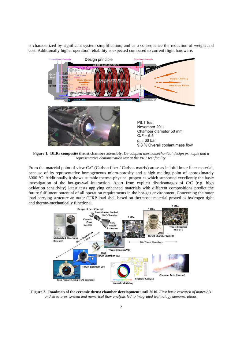
The intermediately well-known development program of transpiration cooled and cryogenically operated CMC rocket thrust chambers at DLR is structurally affected in general by the combination of CMC materials at the inner chamber liner and an outer load carrying shell made of carbon fiber reinforced plastics (CFRP). An illustration of the current design status is given in figure 1. The picture also presents an important demonstration test under relevant operation conditions at DLRs renewed P6.1 test facility. The idea of a ceramic rocket thrust chamber came up in the middle of the nineties. Expeditiously the application potential of micro-porous CMCs aiming on transpiration cooled high temperature structures became visible. Consequently first system analysis and the investigation of structural chamber approaches started. In parallel numerical flow analysis has been and will be performed in the near future to handle the behaviour of the coupled coolant-hot-gas-flow. Figure 2 shows the roadmap of the previous works. After positive experience over the first years a de-coupled structural design crystallized as being constructive. It
* Scientist, Space System Integration, Pfaffenwaldring 38 - 40. + Scientist, Ceramic Composites and Structures, Pfaffenwaldring 38 - 40. † Head of department, System Integration, Pfaffenwaldring 38 – 40. # Head of department, Ceramic Composites and Structures, Pfaffenwaldring 38 – 40.
2
is characterized by significant system simplification, and as a consequence the reduction of weight and cost. Additionally higher operation reliability is expected compared to current flight hardware.
Figure 1. DLRs composite thrust chamber assembly. De-coupled thermomechanical design principle and a representative demonstration test at the P6.1 test facility.
From the material point of view C/C (Carbon fiber / Carbon matrix) arose as helpful inner liner material, because of its representative homogeneous micro-porosity and a high melting point of approximately 3000 °C. Additionally it shows suitable thermo-physical properties which supported excellently the basic investigation of the hot-gas-wall-interaction. Apart from explicit disadvantages of C/C (e.g. high oxidation sensitivity) latest tests applying enhanced materials with different compositions predict the future fulfilment potential of all operation requirements in the hot-gas environment. Concerning the outer load carrying structure an outer CFRP load shell based on thermoset material proved as hydrogen tight and thermo-mechanically functional.
Figure 2. Roadmap of the ceramic thrust chamber development until 2010. First basic research of materials and structures, system and numerical flow analysis led to integrated technology demonstrations.

3
Figure 3. System evaluation. Transpiration cooled CMC thrust chambers show high efficiency potential.
A new ceramic injector design aiming on highly stable operation of both cryogenic and staged combustion under high temperatures has been kicked off meanwhile. Finally the on-going research on the development of CMC bell nozzle shells, produced via filament winding, shall complete the demonstration of an integrated CMC thrust chamber design. From 2006 until 2010 DLRs transpiration cooled ceramic thrust chamber program was integrated in the KSK-project, which was part of the national Propulsion 2010 research network. In Propulsion 2010 DLR worked closely together with the national space propulsion industry EADS Astrium ST. Since 2011 DLR extends its development portfolio by the improvement of constructive CMC derivatives itself and by introducing CMCs into both regenerative and radiation cooled thrust chamber structures. New technology approaches promise further improvements also in these fields of cooling methods. Apart from this, new promising development results of DLRs ceramic rocket injector technology motivate further investigations on this field. These new technology fields will be presented in future publications. The current works are embedded in DLRs Kerberos program, which is linked closely to the national research network continuation Propulsion 2020.
II. System Analysis Aspects
The system evaluation of some transpiration cooled rocket engine configurations gives an impression of the ranking of DLRs former test results in the campaigns KSK-KT (2008) and KSK-ST5 (2010). In these test campaigns, using mainly oxidation sensitive C/C as inner liner material, the coolant mass flow could not be reduced significantly because of appearing material degeneration effects. Figure 3 shows the relation of combustion chamber pressure and coolant mass flow ratio of representative investigations compared to the test results of DLRs CMC thrust chambers. Considering scaling effects and further residual coolant mass flow reduction potential, the transpiration cooled system approach using more resistant ceramic materials seems to be very promising due to its principal high temperature resistance at the inner liner. Latest tests at the end of 2012, which will be given in future publications, predict a substantial coolant mass flow reduction potential down to values lower than 5 % in chambers of 50 mm of inner diameter. New CMC materials show extreme thermochemical resistance without any damage formation. Considering the scaling aspects, this result promises competitive propellant mixture ratios, compared to current high performance propulsion systems using regenerative cooling. Coolant mass flow ratios of about 0.7 %, predicted in a former PhD thesis, were related to the vulcain full-scale class (figure 3). Down-scaled to the 50 mm chamber, 5 % of coolant mass flow ratio seems to be a promising level. Using carbon fiber based materials like C-SiC (PIP or CVI processing), C/C-SiC (LSI process, DLR) or oxide CMCs like OXIPOL (DLR), WPS (Walter Pritzkow Spezialkeramik), or others, all of these partially hybrid material derivatives show suitable thermochemical resistances, under relevant cooling conditions. Hence today’s available materials are appropriate.

4
Figure 4. CMC thrust chamber assembly. All single parts of the thrust chamber body are assembled without bonding.
Figure 5. Flexible inner liner design. Stacks of completely different material segments are possible.
III. Structural Operation Principle of the Transpiration Cooled Thrust Chamber
DLRs structural CMC chamber concept shows predominantly and specifically de-coupled single parts (figure 4):
1) The inner CMC liner, 2) The outer load carrying housing made of CFRP, which shows a pure hollow-cylindrical shape, 3) Metallic flanges at the front edges adjacent to CFRP and CMC bodies.
The structural operation principle can be described by the following aspects: Firstly the inner liner is
assembled by ring segments which are extracted from flat CMC plates before. The advantage of this practice is given on the one hand by the high grade of material homogeneity as well as highly reproducible material quality, and on the other hand by the simple material production process causing lower manufacturing costs. Subsequently the sorted and aligned segments are stacked together, whereas they are centered one to each other. The complete inner liner assembly will be inserted into the outer CFRP shell without being bonded. To fix the stack securely, the whole inner liner component, which shows the characteristic of a mechanical spring in axial direction, will be compressed from the front edges when being mounted at the outer housing. For this reason additionally a suitable bolt interface has been developed and qualified for the technology demonstration.
The specific design allows flexible fiber lay-up’s or stacks of varying CMC ring segments along the chamber axis. Even rings showing completely different material properties can be stacked without inducing additional thermo-mechanical problems, caused by the mechanical de-coupling (figure 5). Depending on changing chemical hot gas formation along the inner hot gas flow from the injector to the nozzle throat, different material resistance requirements can be adjusted excellently by choosing suitable chemo-physical material properties, ring thicknesses and coolant permeability. Close to the injector a higher amount of free oxygen must be expected near the inner liner surface. In this region the use of highly permeable oxide CMC is beneficial.

5
Figure 6. Thermo-mechanical verification. Numerical design verification and structural tests in an electro-mechanical test machine (Type: Zwick) under ambient and cryogenic temperature conditions. As foreseen the metallic bolt row is the dimensioning component, without any impact on the metal-CFRP-interface.
More downstream the coolant diffusion can be reduced by lower material permeability and in parallel the heat conductivity can be increased by the use of carbon fibers, for instance. In the convergent sub-sonic nozzle region also higher heat conductivity and also higher permeability can be of advantage, just as given in figure 1. Hardware Pre-Qualification From the structural point of view typically three general classes of preparatory qualification works have to be done before considering demonstration tests at the rocket propulsion test benches: Structural analysis, thermo-mechanical pre-tests and leakage checks.
The thermo-mechanical pre-qualification is performed in electromechanical or hydro-mechanical test machines (figure 6). The principally de-coupling design philosophy proves as to be free of interfering loads besides the nominal operation loads. The feature of carrying nominal loads only, extremely simplifies the structural dimensioning effort for every structure component. Concerning tightness the test benches require leakage values lower than 1 * 10-4 mbar l / sec of leakage rate under 5 bars He-pressure. The thermoset material shows no leakage difference compared to regular metals used in standard test samples. The last step of hardware pre-qualification consists in water pressurization tests. Hereby the load carrying chamber housing will be filled with water. Subsequently the inner pressure of twice the nominal test conditions will be applied by a hand-service pump.
IV. Numerical Investigations on the Transpiration Cooled Thrust Chamber
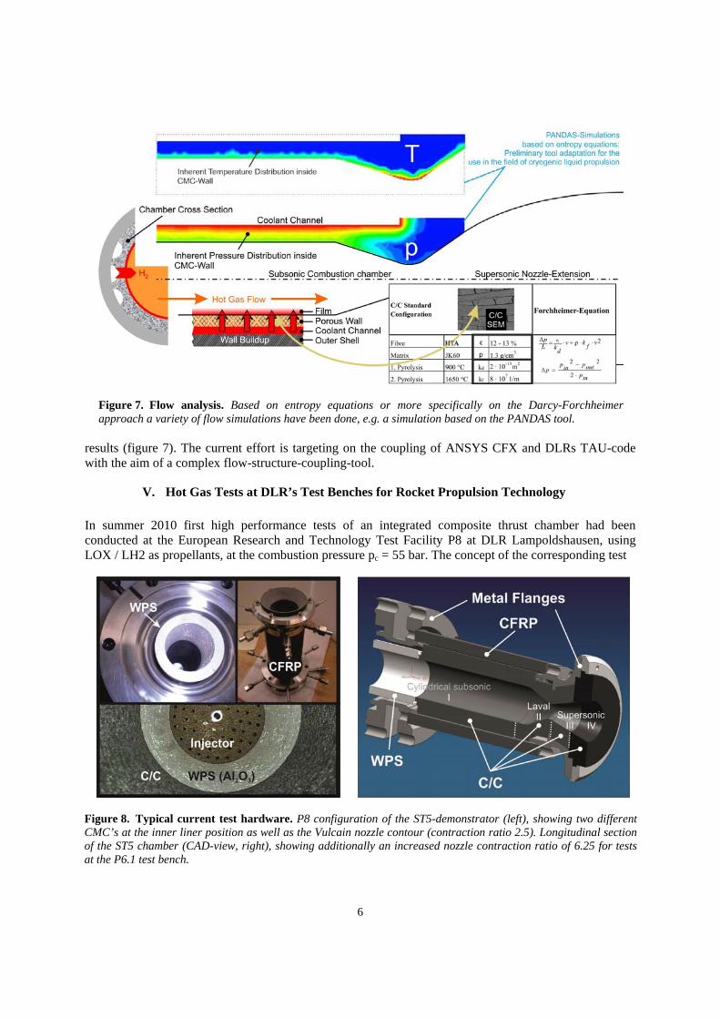
Since the beginning of the ceramic thrust chamber development one major focus was represented by the evaluation of flow characteristic in porous media. In particular the coolant diffusion and the coupling of coolant and hot gas flow are of high interest. Several approaches for the flow investigation were initiated. Two major directions in this evaluation are established, both a pure flow-coupling method and a structure-flow-coupling method. Standard flow computing systems, e.g. ANSYS CFX or FLUENT, are effectual in pure flow coupling. In 2003 DLR started a further approach, wherein the coolant diffusion was calculated by solving entropy equations (based on the PANDAS tool, usually applied in the building industry). In a preliminary development phase, simplified simulations could be conducted, generating good qualitative
6
Figure 8. Typical current test hardware. P8 configuration of the ST5-demonstrator (left), showing two different CMC’s at the inner liner position as well as the Vulcain nozzle contour (contraction ratio 2.5). Longitudinal section of the ST5 chamber (CAD-view, right), showing additionally an increased nozzle contraction ratio of 6.25 for tests at the P6.1 test bench.
Figure 7. Flow analysis. Based on entropy equations or more specifically on the Darcy-Forchheimer approach a variety of flow simulations have been done, e.g. a simulation based on the PANDAS tool.
results (figure 7). The current effort is targeting on the coupling of ANSYS CFX and DLRs TAU-code with the aim of a complex flow-structure-coupling-tool.
V. Hot Gas Tests at DLR’s Test Benches for Rocket Propulsion Technology
In summer 2010 first high performance tests of an integrated composite thrust chamber had been conducted at the European Research and Technology Test Facility P8 at DLR Lampoldshausen, using LOX / LH2 as propellants, at the combustion pressure pc = 55 bar. The concept of the corresponding test

7
0
10
20
30
40
50
60
70
0 5 10 15 20 25
U_P_DF_C1
U_P_IF_C2
U_P_Z_N
U_P_IF_CC
U_P_I_O
U_P_I_H
p /
bar
t / s
P6.1 - MT5-A Campaign - 2012 Q1 T06 - HOTRUN - Pressure Courses
Pcc icy!
Test configurationpc =60bar
0
50
100
150
200
250
300
0 5 10 15 20 25 30 35
U_T_IF_C
U_T_IF_K1
U_T_IF_K2
U_T_DF_K1
T /
K
t / s
P6.1 - MT5-A Campaign - 2012 Q1 T06 - HOTRUN - Temperature Courses Test configurationpc =60bar
Figure 9, Set of test results - MT5-A campaign (P6.1). 20 s long P6.1-hot-run at a pressure level of p = 60 bar after 15 seconds of pre-cooling.
hardware, the KSK-ST5-demonstrator (figure 8), had been designed twice, applicable both for tests at the P8 test bench, using the Vulcain nozzle contour and for tests at the renewed P6.1 test bench, using the contraction ratio of 6.25 because of lower test bench performance. The design concept allows an easy replacement of the CMC nozzle set (three C/C segments II – IV) corresponding to each nozzle contour, and remaining the cylindrical CMC components. In November 2011 the test campaign MT5-A happened, representing the first tests of the integrated ceramic thrust chamber at the renewed P6.1 test bench, using the chamber configuration as given in figure 8 on the right hand side. In this campaign the gaseous hydrogen ranged at a temperature level of about 100 – 150 K, whereas the oxidizer (LOX) was in liquid condition. The chamber pressure amounted up to ~ 65 bars. Figure 9 shows the results of a very important test configuration. The system’s cooling efficiency could be proved by the demonstration of < 10 %, which represents a high efficiency level, considering system analysis aspects (chapter II). The temperature courses promise further coolant reduction as mentioned.
VI. CMC Nozzle Extensions for Future Aerospace Propulsion Applications
Carbon-fiber-reinforced silicon carbide matrix composites are still considered to be one of the most promising material candidates to replace heavy refractory superalloys in future rocket propulsion applications, e. g. rocket nozzle extensions, due to their excellent thermal and mechanical properties in high temperatures and its much lower material density to increase the payload capacities. A variety of different processing routes, like chemical vapor infiltration (CVI), liquid polymer infiltration and pyrolysis (PIP) and reactive melt infiltration (RMI) or combinations of those have been studied intensively in the last decades (figure 10). In the field of carbon-fiber-reinforced silicon carbide matrix composites for future rocket nozzle structures the DLR focuses on the development of competitive C/C-SiC materials using the liquid silicon infiltration route (LSI) in combination with effective fiber preform techniques like filament winding which is indispensable for axis-symmetric structures. The possible use of adapting fiber architectures result in novel LSI-based C/C-SiC materials with different final microstructures and mechanical properties which are currently studied. Processing costs and times are significantly high using CVI or PIP routes. The latter CMC materials require a complex fiber coating to accomplish damage tolerant fracture behavior and they additionally show high open porosities due to their specific processing. The LSI based C/C-SiC materials are featured by short processing times (2-3 weeks) and cheap raw materials (C-fiber, C-precursor and silicon) which

8
Figure 11. Summary of the current works on DLRs CMC nozzle extensions.
are commercially available. Within LSI-based C/C-SiC materials no fiber coating is needed because carbon filaments are embedded in a dense C matrix which is surrounded by SiC, which results in low open porosities. Dense CMC materials are required for most aerospace propulsion applications.
Figure 10. Typical CMC microstructures. Left: CVI-based SiC/SiC. Right: LSI-based C/C-SiC via filament
winding. In the recent past the DLR demonstrated the fabrication of sub-scale C/C-SiC nozzle structures (figure 11). In order to manufacture a nozzle structure with a complex inner wall contour, consisting of changing diameters over the axial length direction, sophisticated software is essential to simulate the desired fiber architectures. The combination of different fiber orientations within the fiber lay-up must meet the final thermal and structural loads, specific processing needs to accomplish a desired microstructure which will provide sufficient mechanical material properties as well as basic filament winding limitations. First step in the manufacturing process is the development of a suitable fiber architecture using Cadwind filament winding software followed by the fabrication of the fiber preform using wet filament winding technique and curing to generate a CFRP green body. The green body is then processed by standard LSI-fabrication, including carbonization (pyrolysis) and siliconization. Due to shrinkage effects during pyrolysis the risk of delamination has to be avoided accurately. Sophisticated fiber architecture is used where outer fiber layers have decreasing fiber orientations with respect to the rotation axis. Any type of contour deformation during processing, like ovalisation, is prevented by supporting the inside of the CRFP nozzle preform with graphite support cores. This procedure leads to a full axis-symmetric inner contour with no signs of contour deformations. After siliconization the C/C-SiC structure will usually be examined by means of CT-analysis to identify any delamination or other characteristic flaws, like pores. In addition to the detection of imperfections,

9
like pores and delamination, CT-analysis is also useful to provide an accurate determination of the wall thickness for changing diameters as well as the inner contour. For the first time hot-gas tests of novel C/C-SiC nozzle structures are planned at the DLR test bench facility P6 in Lampoldshausen, Germany at the end of 2013.
VII. Conclusion and Outlook The integrated design principle of DLR’s transpiration cooled CMC thrust chamber could be demonstrated successfully from multiple points of view. The general design succeeds currently on the basis of an extensively de-coupled load philosophy. The combination of different CMC’s for the inner chamber liner is applicable, corresponding to the changing hot gas conditions along the chamber axis. Aspects of the general system analysis indicate high efficiency of the transpiration cooled CMC rocket thrust chamber technology. Remaining thermo-chemical pre-verifications of interesting inner CMC liner materials are expected to be completed in the near future, supported by newest test results at the relevant European rocket propulsion test benches. Numerical simulations concerning flow analysis accompany the ceramic thrust chamber development. New technology approaches concerning regenerative and radiation cooling, as well as CMC rocket injectors and nozzle extensions will extend DLRs future research portfolio in the field of ceramic rocket propulsion technology.
References
1A. Herbertz, M. Ortelt, I. Mueller, H. Hald, Transpiration-Cooled Ceramic Thrust Chamber
Applicability for High-Thrust Rocket Engines, June 29 – August 1 2012, 48th AIAA/ASME/SAE/ASEE Joint Propulsion Conference and Exhibit.
2Mueller, I., Voggenreiter, H., Untersuchung der Interaktion zwischen einer reaktiven Heissgasströmung und einer transpirativ gekuehlten faserverstaerkten keramischen Raketenbrennkammer, September 27 - 29 2011, 60. Deutscher Luft- und Raumfahrtkongress 2011, Bremen, Germany.
3Greuel, D., Herbertz, A., Haidn, O.J., Ortelt, M., Hald, H., Transpiration Cooling Applied to C/C Liners of Cryogenic Liquid Rocket Engines,, AIAA 2004-3682, July 11 - 14 2004, 40th AIAA/ASME/SAE/ASEE Joint Propulsion Conference and Exhibit.
4Hald, H., Ortelt, M., Ghadiani, S., Herbertz, A., Greuel, D., Haidn, O.J.: Application of Fiber Reinforced C/C Ceramic Structures in Liquid Rocket Engines, International Conference (Space 2003), „Space Challenge in 21st Century. 100 Years after the Tsiolkovskiy Idea on Space Missions using Reactive Motors“, Moscow-Kaluga, Russia, 15-19 September 2003.
5Heidenreich, B., Herstellung von Faserkeramiken nach dem Fluessigsilicierverfahren (LSI-Technik), in: Keramische Verbundwerkstoffe, Weinheim, Wiley-VCH, pp. 48-75, 2003.
6Heidenreich, B., Krenkel, W., Friess, M., Gedon, H., Net Shape manufacturing of Fabric Reinforced Oxide/Oxide Components via Resin Transfer Moulding and Pyrolysis, in: Keramische Verbundwerkstoffe, Weinheim, Wiley-VCH, pp. 48-75, 2003.
7Krenkel, W.: Entwicklung eines kostengünstigen Verfahrens zur Herstellung von Bauteilen aus keramischen Verbundwerkstoffen, Institut für Bauweisen und Kostruktionsforschung, Stuttgart, 2000
8Lezuo, M., Haidn, O.J., Active Cooling Using Transpiration Devices, 1995, 2nd European Workshop on Thermal Protection Systems, Stuttgart.

10
9Lezuo, M., D., Haidn, O.J., Transpiration Cooling H2/O2 – Combustion Devices, January 26-30 2004, 28th International Cocoa Beach Conference on Advanced Ceramics and Composites, Cocoa Beach, USA
10Ortelt, M., Fischer, I., Hald, H., Greuel, D., Suslov, D., Haidn, O.J., Empirical Verification of Effusion Cooled CMC Rocket Thrust Chambers, AIAA 2005-3569, July 10–13 2005, 41st AIAA/ASME/SAE/ASEE Joint Propulsion
11Pritzkow, W.E.C., Deuerler, F., Koch, D., Ruedinger, A., Tushtev, K., Versagenseffekte auf Grund von Makro-Fehlstellen in Oxidkeramischen Verbundwerkstoffe, Bayreuth, Germany, April 1–3 2009, 17. Symposium Verbundwerkstoffe und Werkstoffverbunde.
12Ruedinger, A., Glaubitt, W., Oxidkeramische Matrices basierend auf Sol-Gel-Vorstufen fuer die Herstellung oxidkeramischer Faserverbundwerkstoffe, 2005, cfi/Ber. DKG 82 No. 13, 51-54.
13Serbest, E.: Untersuchung zur Anwendung der Effusionskühlung bei Raketenbrennkammern, Dissertation, RWTH Aachen, Institut für Luft- und Raumfahrttechnik, Aachen 2002.
14 N.N.: Forschungstool PANDAS: FE-System zur Simulation von Sonderproblemen der Bodenmechanik (Berechnung volumetrisch stark gekoppelter Festköprer-Fluid-Problemen durch poröse Körper), www.get-pandas.com, 2006.
15 Breede, F. (2012). Mechanical and Microstructural Characterization of C/C-SiC Manufactured Via
Triaxial and Biaxial Braided Fiber Preforms Mechanical Properties and Performance of Engineering Ceramics and Composites VII: Ceramic Engineering and Science Proceedings, Volume 33 Issue 2 (Vol. 33, pp. 183-194): Wiley.
16 Breede, F., & Frieß, M. (2010). Mechanical properties and microstructures of C/C-SiC composite
plates by wet filament winding technique. In W. K. a. J. Lamon (Ed.), High Temperature Ceramic Materials and Composites - Proceedings of 7th Int. Conference on High Temperature CMCs (HT-CMC-7) (pp. 276-282). Germany.
17 Breede, F., Hofmann, S., Klatt, E., & Denis, S. (2011). Influence of Fiber Orientation on the Mechanical Properties and Microstructure of C/C-SiC Composite Plates Produced by Wet Filament Winding Technique Processing and Properties of Advanced Ceramics and Composites III (pp. 1-10): John Wiley & Sons, Inc.
18 F. Breede, M. Frieß, R. Jemmali, D. Koch, H. Voggenreiter, V. Frenzel, K. Drechsler. Mechanical and Microstructural Characterization of C/C-SiC Manufactured via Triaxial and Biaxial Braided Fiber Preforms. 36th International Conference on Advanced Ceramics and Composites (ICACC), 2012.


![Rocket! :]](https://static.fdocuments.in/doc/165x107/558c01cdd8b42abd5b8b4570/rocket-.jpg)