
CTs & VTs
48
Current and Voltage Current and Voltage Transformers Lecture 5
-
Upload
sulemankhalid -
Category
Documents
-
view
191 -
download
7
Transcript of CTs & VTs

Current and Voltage Current and Voltage TransformersLecture 5

OutlinesIntroductionIntroduction
Voltage transformers• Equivalent circuit• Errors• Burden• Selection of VTs• Capacitor voltage transformers
Current transformers• Equivalent circuit• Errors
AC i• AC saturation• Burden• Selection of CTs• DC saturation
P ti h ki ith CT• Precautions when working with CTs

Introduction
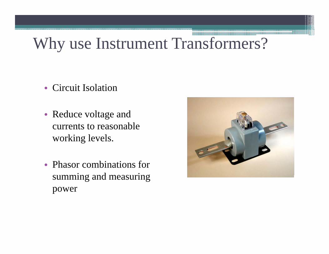
Why use Instrument Transformers?Why use Instrument Transformers?
• Circuit Isolation
R d l d• Reduce voltage and currents to reasonable working levels. g
• Phasor combinations for s mming and meas ringsumming and measuring power

IntroductionIntroduction
• Instrument Transformer (IT) - A high precision transformer designed to provide input into measurement, protection and/or control equipment.
E l V lt t• Examples: VoltmetersAmmetersWatthourWatthourMetersRelaysy

Introduction
• Voltage Transformer (VT)An instrument transformer used to reflect a primary voltage into a secondary voltage through a magnetic medium. Always connected in parallel with primary conductor across a circuit load.Secondary (measuring) voltage is usually 115 or 120 volts
i ll Th d lt l l i l t d f fnominally. The secondary voltage level is selected for ease of measurement and safety.
Control Po er Transformer (CPT)• Control Power Transformer (CPT) Designed to provide power for contractors, relays and devices with high inrush currents, Regulation is not as critical.

Current TransformersCurrent Transformers• Current Transformer (CT) An
instrument transformer used to reflect ainstrument transformer used to reflect a primary current into a secondary current through a magnetic medium. Always connected in series with the primary conductor. The nominal secondary current is often a 5 amp basis for ease of measurement. Construction can be one primary turn (Window, donut, or Bar type), or wound primary turns (usually for low
ti )ratios)

Potential Transformer

Potential Transformers
VVPP
VsVsVsVs
Relay

POTENTIAL TRANSFORMERSPOTENTIAL TRANSFORMERSPOTENTIAL TRANSFORMERSPOTENTIAL TRANSFORMERS
Electromagnetic Voltage Electromagnetic Voltage TransformersTransformersElectromagnetic Voltage Electromagnetic Voltage TransformersTransformers
Capacitive Voltage Capacitive Voltage TransformersTransformersCapacitive Voltage Capacitive Voltage TransformersTransformers
cccc

Potential TransformerE i ti l t th d t f • Error is proportional to the drop on transformer winding impedance▫ Winding impedance should be low to avoid large ▫ Winding impedance should be low to avoid large
error• Saturation▫ Affect the accuracy of the Instrument
Transformers,▫ Should operate on the linear range
• Output Voltage to the relay usually between 120/69V120/69V

Equivalent Circuit
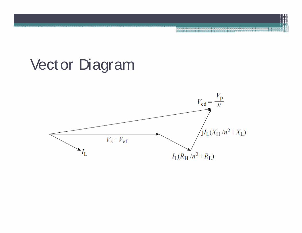
Vector Diagramg

Errors
• For Ideal Transformer▫ Vp/n Vs no error▫ Vp/n = Vs no error
• For Practical transformer▫ Vp/n ≠ Vs errorVp/n ≠ Vs error
100*Vp
VpnVsErrorVt
• Error should be kept small within 3% of the
Vp
output voltage and should be accounted for.
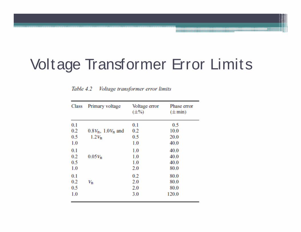
Voltage Transformer Error Limitsg

Burden• The standard burden for voltage transformers is • The standard burden for voltage transformers is
usually expressed in volt-amperes (VA) at a specified power factor.specified power factor.
• Std ANSI 57.13
Selection of VTs• Voltage transformers are connected between phases or between • Voltage transformers are connected between phases, or between
phase and earth. • The connection between phase and earth is normally used with
groups of three single phase units connected in star at substations groups of three single phase units connected in star at substations operating with voltages at about 34.5 kV or higher, or when it is necessary to measure the voltage and power factor of each phase separately.separately.
• The nominal secondary voltages are generally standardised at 115 and 120V.
• In order to select the nominal power of a VT, it is usual to add In order to select the nominal power of a VT, it is usual to add together all the nominal VA loadings of the apparatus connected to the VT secondary winding.
• In addition, it is important to take account of the voltage drops in add t o , t s po ta t to ta e accou t o t e vo tage d ops the secondary wiring, especially if the distance between the transformers and the relays is large.

Capacitive VTs

TEN EQUAL CAPACIATORSCAPACIATORS
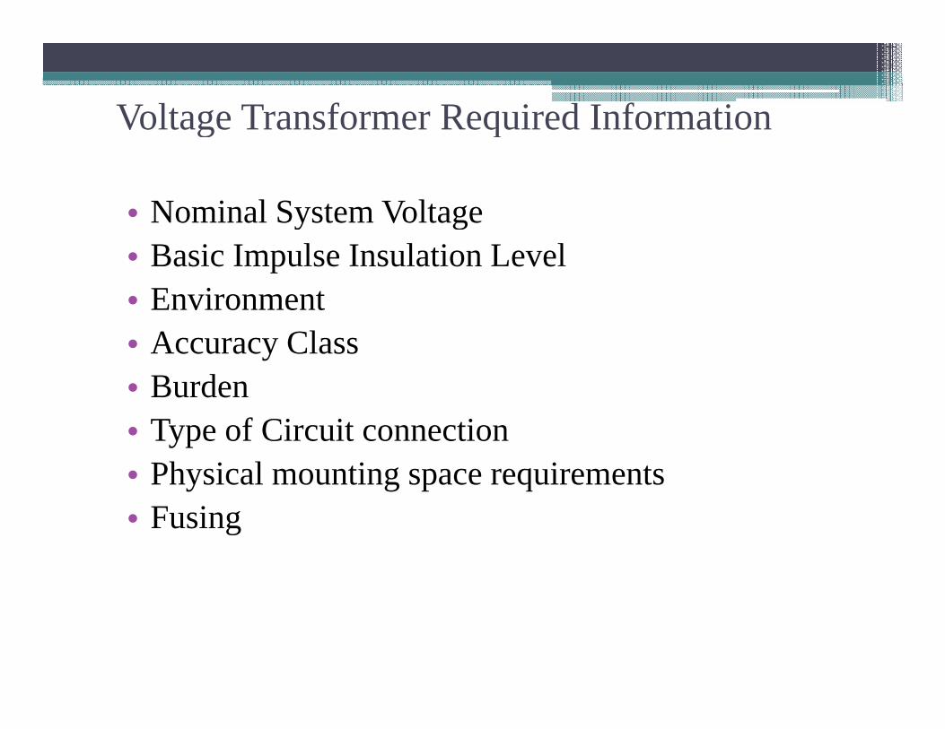
Voltage Transformer Required Informationg q
• Nominal System Voltagey g• Basic Impulse Insulation Level• Environment• Accuracy Class• Burden• Type of Circuit connection• Physical mounting space requirements• Fusing

Current TransformerEquivalent circuitErrorsAC saturationBurdenS l i f CTSelection of CTsDC saturationPrecautions when working with CTs

CURRENT TRANSFORMERS
TYPES OF C.T. CONSTRUCTION
The most common type of C.T. construction is the `DOUGHNUT' type. It is constructed of an iron toroid, which forms the core of the transformer, and is wound with secondary turns.
Secondary Winding Primary Conductor
Iron Core

Bushing CTg
Oil CircuitBreaker Bushings
Fixed Contact
Current Transformers
Moving Contact
Contact

Free Standing or Post CTThe Straight-Through type of construction is shown below:
Free Standing or Post CT

Hairpin Constructionp

CURRENT TRANSFORMER THEORYCURRENT TRANSFORMER THEORY & CHARACTERISTICS
Current Transformers for protective relaying purposes must reproduce the primary currentpurposes must reproduce the primary current accurately for all expected fault currents.
Th i t f th C T i t i i d The importance of the C.T. maintaining good accuracy, and not saturating at the maximum fault current is most critical on differentialfault current, is most critical on differential protection. This can be critical when applied to Bus Protection and Transformer Protection.

When C.T.'s are used for metering purposes, they must have a high degree of accuracythey must have a high degree of accuracy only at LOAD currents. i.e. 0 to 5 Amps secondary. There is no need for a high degree of accuracy for fault currents, and it is quite acceptable for a metering C.T. to saturate when fault current flows through itwhen fault current flows through it.
A C T for protective relaying purposes mayA C.T. for protective relaying purposes may typically have a knee point at 500 volts, whereas a metering C.T. may saturate at well g ybelow 100 volts.

What is your application?
If your application is metering , how high do I need to go in current? 2 times ?go in current? 2 times ?
If your application is relaying how high do I need toIf your application is relaying, how high do I need to go in current? 20 times ?

CT CLASSIFICATION for RELAYINGCT CLASSIFICATION for RELAYING
Protection Class CT’sProtection Class CT’s -- Must supply 20 times rated currentMust supply 20 times rated current
10 C 40010 C 400Format
L ttAccuracy Voltage at 20 times CT
T = Determined by test
Letter Voltage at 20 times CT
yC = CalculatedK = CalculatedL = Low internal secondary impedanceH = High internal secondary impedance

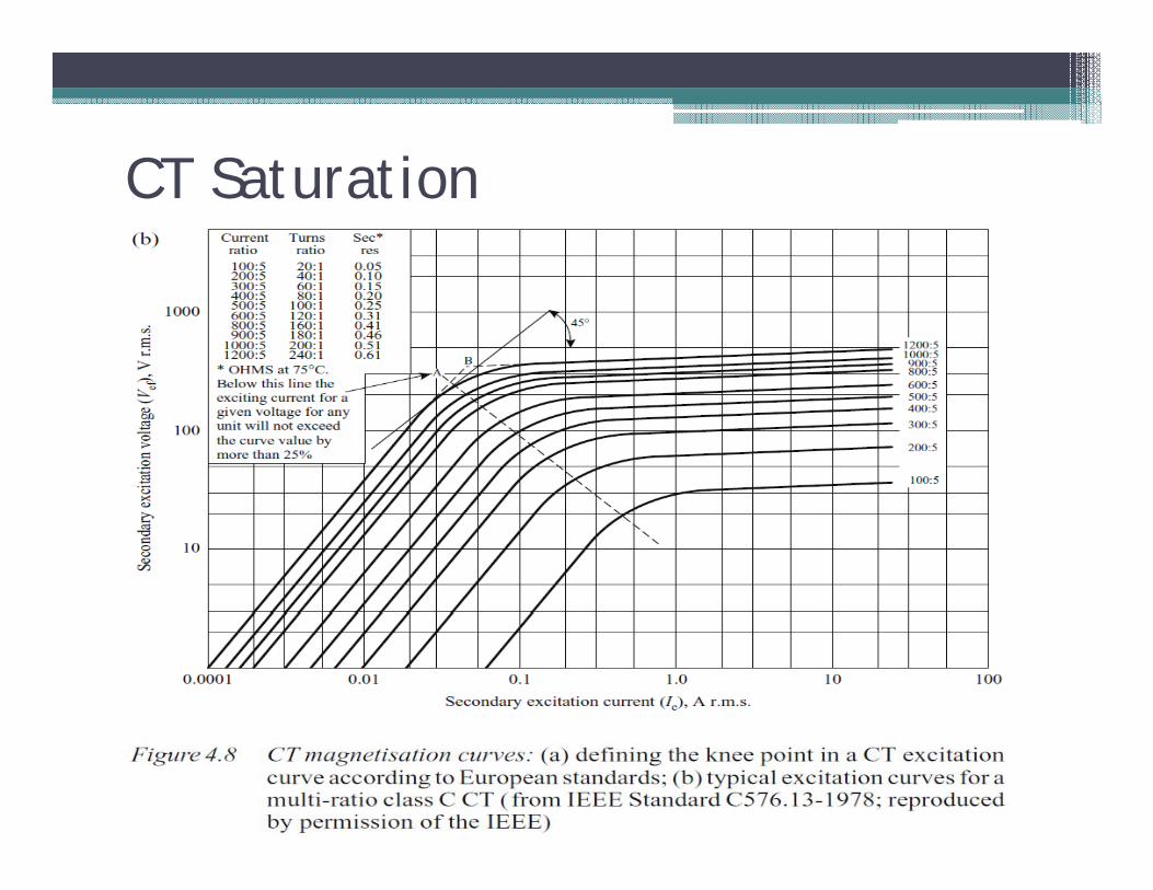
MAGNETIZATION CURVES FOR A TYPICAL CTMAGNETIZATION CURVES FOR A TYPICAL CT
Knee Point = VxKnee Point = VxKnee Point = VxKnee Point = VxKnee Point VxKnee Point VxKnee Point VxKnee Point Vxn n n n 45 degrees
Exci
tatio
nEx
cita
tion
Volta
geVo
ltage
Exci
tatio
nEx
cita
tion
Volta
geVo
ltage
Excitation CurrentExcitation CurrentExcitation CurrentExcitation Current
EE VVEE VV

Important:Important:Instrument Transformer Accuracy is Al F i f A li dAlways a Function of Applied Burden.Lead wires for CTs can be significantsignificant.

A current transformer for metering purposes may typically have an accuracy of 0.3%. The C.T. must maintain this accuracy for normal load currents,maintain this accuracy for normal load currents, provided the rated burden on the C.T. is not exceeded. It is quite acceptable, and in fact desirable, for the C.T. to saturate when fault current flows The accuracy for ato saturate when fault current flows. The accuracy for a typical metering C.T. is specified as:
0.3 M 0.9
O.3% METERING O.9 OHMS BURDEN
This metering C T has an accuracy of 0 3% when theThis metering C.T. has an accuracy of 0.3% when the connected burden does not exceed 0.9 OHMS.
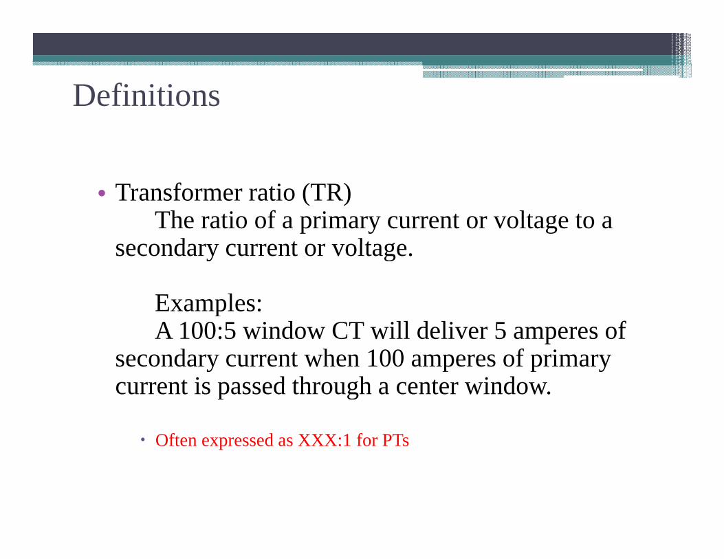
DefinitionsDefinitions
• Transformer ratio (TR)The ratio of a primary current or voltage to a
secondary current or voltagesecondary current or voltage.
Examples: pA 100:5 window CT will deliver 5 amperes of
secondary current when 100 amperes of primary current is passed through a center windowcurrent is passed through a center window.
Often expressed as XXX:1 for PTs

Equivalent Circuit
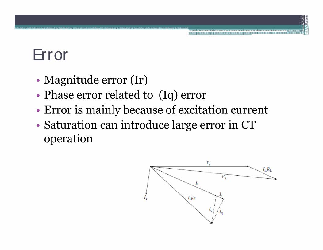
ErrorM it d (I )• Magnitude error (Ir)
• Phase error related to (Iq) error• Error is mainly because of excitation current• Error is mainly because of excitation current• Saturation can introduce large error in CT
operationoperation
CT S t tiCT Saturation

Burden

Burden

Accuracy TerminologyAccuracy Terminology
Ratio Correction factor (RCF)The measure of transformer amplitude accuracy. I E th ti f th k d (t ) ti t th t lI.E. the ratio of the marked (true) ratio to the actual (performance) ratio of a transformer.
Primary = Secondary(measured) * Marked ratio * RCF

Accuracy TerminologyAccuracy Terminology
Phase Angle (PA)The phase displacement between the primary and secondary circuit of an instrument transformer. Usually expressed in minutes.

Accuracy TerminologyAccuracy Terminology
Transformer Correction factor (TCF)The ratio of true to measured watts or watt-hours divided by the marked ratio. The TCF is the product of the ratio correction factor and phase angle
ti f t th t it i d t i d b thcorrection factor, so that it is determined by the ratio error, the phase angle shift and the power factor of the loadfactor of the load.

Standard CT BurdensStandard CT Burdens
Standard CT burdens are defined in IEEE Std. C57-13-1993 Metering burdens are B0.1, B0.2, B0.5, B0.9, and B1.8 where each number represents the total i d t 0 9 f t VA f himpedance at a 0.9 power factor. VA for each burden is 2.5, 5.0, 12.5, 22.5, and 45.Relay burdens are B1 B2 B4 and B8 where eachRelay burdens are B1, B2, B4 and B8 where each number represents the total impedance at a 0.5 power factor.p

Definition
• PolarityTh i d d fThe primary and secondary transformer
connections must be marked so that the relative instantaneous direction of current flow can beinstantaneous direction of current flow can be identified.
• The primary is often marked “H1” and theThe primary is often marked H1 and the secondary “X1”.
• Another common practice is to use “polarity dots” p p yto identify in phase terminations.


100:5 C.T. Secondary Winding Resistance = .062 ohm
Resistance of Cable from C.T. to Relay and back = .1 ohms
Resistance of Relay Coil = .02 ohms
Total Resistance = 182 ohmsTotal Resistance = .182 ohms
062 02.062
.1.02
If we have a fault of 2,000 amps and the C.T. ratio is 100:5 then the C.T. secondary current is 100 amps. Therefore we must be able to produce a total y p pvoltage of 100 amps x .182 ohms = 18.2 Volts. For the C.T. to operate accurately without saturating for this fault current the knee point must be above 18.2 Volts.

200:5 C.T. Secondary Winding Resistance = .125 ohm
Resistance of Cable from C.T. to Relay and back = .1 ohms
Resistance of Relay Coil = .02 ohms
Total Resistance = 245 ohmsTotal Resistance = .245 ohms
125 02.125
.1.02
If we have a fault of 4,000 amps and the C.T. ratio is 200:5 then the C.T. secondary current is 100 amps. Therefore we must be able to produce a total y p pvoltage of 100 amps x ..245 ohms = 24.5 Volts. For the C.T. to operate accurately without saturating for this fault current the knee point must be above 24.5 Volts.
At this point on the curve we are at .2 amps exciting current out of 100 amps so we are .2/100 or .2% accurate at 20 times CT.
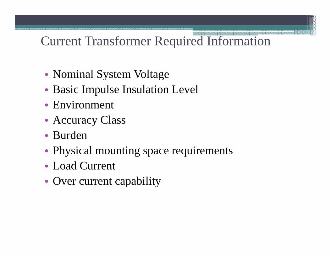
Current Transformer Required Informationq
• Nominal System Voltagey g• Basic Impulse Insulation Level• Environment• Accuracy Class• Burden• Physical mounting space requirements• Load Current• Over current capability

Relay ClassIEEE l l i d fi d i t f th lt CTIEEE relay class is defined in terms of the voltage a CT can
deliver at 20 times the nominal current rating without exceeding a 10% composite ratio error.
–For example, a relay class of C100 on a 1200:5 CT means that the CT can develop 100 volts at 24,000 primary amps (1200*20) without exceeding a 10% ratio error.
Aside: This C100 is associated with a 1 ohm burden in the standard because: 5 amps secondary * 20 times over-current * 1 ohm = 100 volts. So C100, C200, C400, and C800, corresponds to 1, 2, 4, and 8 ohms, respectively.
–A relay class assignment alone provides limited information. More information for relay calculations can ybe provided in an excitation curve…

![Administering Cisco VTS · admin@VTS-A:~$ sudo su [sudo] password for admin: Step2 SourcetheVTSenvironment. root@VTS-A:# source /etc/profile.d/ncs.sh Step3 VerifyVTSstatus. root@VTS-A:#](https://static.fdocuments.in/doc/165x107/5ec8e3d704a90406890d6ec6/administering-cisco-vts-adminvts-a-sudo-su-sudo-password-for-admin-step2.jpg)


![Mower County transcript. (Lansing, Minn.) 1897-11-17 [p ].€¦ · cts cts cts cts cts cts cts cts cts JACKETS. Ladies' heavy Boucle Jackets, the latest style, and worth $5.00, only](https://static.fdocuments.in/doc/165x107/5fce2fde3593f56f3c130835/mower-county-transcript-lansing-minn-1897-11-17-p-cts-cts-cts-cts-cts-cts.jpg)