
CTI OS System Manager Guide for Cisco Unified ICM/Contact ... · CTI OS System Manager Guide for...
178
CTI OS System Manager Guide for Cisco Unified ICM/Contact Center Enterprise & Hosted Release 10.5(1) First Published: June 18, 2014 Americas Headquarters Cisco Systems, Inc. 170 West Tasman Drive San Jose, CA 95134-1706 USA http://www.cisco.com Tel: 408 526-4000 800 553-NETS (6387) Fax: 408 527-0883
Transcript of CTI OS System Manager Guide for Cisco Unified ICM/Contact ... · CTI OS System Manager Guide for...

CTI OS System Manager Guide for Cisco Unified ICM/Contact CenterEnterprise & Hosted Release 10.5(1)First Published: June 18, 2014
Americas HeadquartersCisco Systems, Inc.170 West Tasman DriveSan Jose, CA 95134-1706USAhttp://www.cisco.comTel: 408 526-4000 800 553-NETS (6387)Fax: 408 527-0883

Cisco and the Cisco logo are trademarks or registered trademarks of Cisco and/or its affiliates in the U.S. and other countries. To view a list of Cisco trademarks, go to this URL: http://www.cisco.com/go/trademarks. Third-party trademarks mentioned are the property of their respective owners. The use of the word partner does not imply a partnershiprelationship between Cisco and any other company. (1110R)
© 2003-2014 Cisco Systems, Inc. All rights reserved.

C O N T E N T S
P r e f a c e Preface ix
Change History ix
About this Guide ix
Audience x
Organization of this Guide x
Related Documents xi
Documentation and Support xi
Field Alerts and Field Notices xi
Documentation Feedback xi
Conventions xii
C H A P T E R 1 Introduction 1
Overview of CTI OS 1
Advantages of CTI OS as Interface to Unified ICM Enterprise 2
Key Benefits of CTI OS for CTI Application Developers 3
System Manager Responsibilities 4
System Requirements 4
Set User Privileges 4
Silent monitoring 5
Silent Monitor Differences Between Unified CM and CTI OS 5
Unified CM-Based Silent Monitoring 6
Unified CM Silent Monitor Advantages 7
Unified Communications Manager Silent Monitor Limitations and Restrictions 7
CTI OS-Based Silent Monitoring 8
Network Topology for Silent Monitoring 9
Unified CM-Based Silent Monitoring 9
CTI OS-Based Silent Monitoring 10
CTI OS System Manager Guide for Cisco Unified ICM/Contact Center Enterprise & Hosted Release 10.5(1) iii
Silent Monitoring and Citrix Topology 11
Silent Monitoring and Mobile Agent Topology 11
Calculation of Additional Needed Bandwidth 12
C H A P T E R 2 CTI OS Server Installation 13
CTI OS Server Installation Guidelines 13
Upgrade from Previous Version 14
Install CTI OS Server 14
Uninstalling CTI OS Server 26
Determine Version Number of Installed Files 27
C H A P T E R 3 CTI Toolkit Desktop Client Installation 31
Upgrade from Previous Version 32
Install Cisco CTI Toolkit Desktop Client Component 32
Localization 36
Installed Files 36
Uninstall CTI Toolkit 39
Determine Version Number of Installed CTI Toolkit Files 39
Unified CM Intercept Configuration Requirement 41
Configure Supervisory Assistance Features 41
Video Configuration 45
C H A P T E R 4 CTI OS Silent Monitor Installation and Configuration 47
Silent Monitor Service Installation and Configuration 47
Silent Monitor Service Overview 47
CTI OS Connections 48
How desktops Connect to Silent Monitor Services 48
Configure ESXi Server 49
Configure LAN Switch 50
Run Silent Monitor Service Installer 50
Sign a Silent Monitor Server Certificate Request with Self-Signed CA 54
Sign a Silent Monitor Service Certificate Request with Third-Party CA 55
Additional Configuration Steps 55
Rerunning CTI OS Server Setup 55
Silent Monitor Service Installation in Citrix Environment 56
CTI OS System Manager Guide for Cisco Unified ICM/Contact Center Enterprise & Hosted Release 10.5(1)iv
Contents
Additional Configuration for Mobile Agent Environments 56
Silent Monitor Service Clusters 57
Installation of Silent Monitor Service with Windows Firewall Service Enabled 57
Harden Silent Monitor Server Security 58
Add Silent Monitor Service to Windows Firewall Exceptions 58
Silent Monitor Service Deployments 59
Unified CCE Deployment 59
Citrix Deployment 60
Mobile Agent Using Analog/PSTN Phone 61
Mobile Agents IP Phones Topology 62
Mobile Agent Using IP Phone 62
Mobile Agent Using IP Phone and Citrix 62
Mobile Agent Using Analog/PSTN Phone and Citrix 63
C H A P T E R 5 CTI OS Component Installation 65
Silent Installation of CTI OS Components 65
Create a Response File 66
Run CTI OS Silent Install on Other Machines 67
Uninstall Components 67
Recover from Failed Installation of CTI OS 68
C H A P T E R 6 Unified Communications Manager-Based Silent Monitor Configuration 69
Unified CM Silent Monitor Configuration and Administration 69
Enable Built-In Bridge for Agent Device 70
Add PG User to Standard CTI Allow Call Monitor 70
Monitoring Calling Search Space 71
Monitoring Notification Tone 73
CTI OS and Silent Monitoring 74
Restrictions 75
Phones 75
Cisco Unified CM 75
CTI OS Desktop Versions 75
Recording Applications 75
Transfer and Conferencing of Monitored Calls 75
CTI OS System Manager Guide for Cisco Unified ICM/Contact Center Enterprise & Hosted Release 10.5(1) v
Contents
C H A P T E R 7 CTI OS Security 77
CTI OS Security Certificate Configuration 77
CTI OS Security Setup Programs 77
Sign CTI Toolkit Desktop Client Certificate Request with Self-Signed CA 78
Sign CTI OS Server Certificate Request with Self-Signed CA 79
Sign CTI Toolkit Desktop Client Certificate Request with Third-Party CA 80
Sign CTI OS Server Certificate Request with Third-Party CA 80
CTI OS Security Passwords 81
CTI OS Security Registry Keys 81
Mode Security Monitoring 83
Security Compatibility 83
Wire Level Encryption 84
Authentication Mechanism 84
C H A P T E R 8 CTI OS Configuration 85
Use Windows Registry Editor 86
Silent Monitor Type Configuration for CTI OS 87
Virtual Desktop Infrastructure 88
CTI OS Desktop Installations on VDI Agent Desktops 88
Prerequisites 88
Install CTI OS Desktop on VDI Agent 88
Notes and Restrictions 88
Silent Monitoring 88
ThinApp 88
CTI Driver Key 89
EMS Tracing Values 90
Server Registry Key 92
Agent Registry Key 92
ReasonCodes Registry Key 95
WrapupStrings Registry Key 95
CallObject Registry Key 96
Connections Registry Key 97
Device Registry Key 98
Peers Registry Key 98
CTI OS System Manager Guide for Cisco Unified ICM/Contact Center Enterprise & Hosted Release 10.5(1)vi
Contents
Peripherals Registry Key 99
SkillGroup Registry Key 100
Supervisor Registry Key 100
ThreadPoolSize Registry Key 100
TimerService Registry Key 101
MainScreen Registry Key 101
UCCE Silent Monitor Configuration 102
ConnectionProfiles Registry Key 103
SilentMonitorService Subkey 106
Configuration of Additional Connection Profiles 107
Creation of Second Profile 107
Two Profiles for Server- and Desktop-Based Silent Monitoring Scenario 108
Call Appearance Grid Configuration 109
Configure Automatic Call Appearance Grid 112
Customize Agent Statistics Grid Configuration 115
Automatic Skill Group Statistics Grid Configuration 116
Configure Additional Peripherals 118
Quality of Service/Type of Service 118
Basic Configuration 119
Important Additional Configuration Information 119
Caveats 120
C H A P T E R 9 Startup, Shutdown, and Failover 121
Unified CCE Service Control 121
CTI OS Failover 122
Failover of CTI OS Related Components 122
IP Phones 123
Switches 123
Peripheral Gateway 123
CTI Server Failure 123
CTI OS Server Failure 123
C H A P T E R 1 0 Peripheral-Specific Support 125
General Unified ICM Support 125
Peripheral-Specific Terminology 126
CTI OS System Manager Guide for Cisco Unified ICM/Contact Center Enterprise & Hosted Release 10.5(1) vii
Contents
Unified ICM Feature Limitations 127
CTI OS Support 127
Call Events 127
Client Control Requests 129
Peripheral-Specific Limitations and Differences 130
Aspect Contact Server 130
Avaya DEFINITY ECS 130
UCCE 135
UCCE Error Codes 137
Avaya Aura CC (Symposium) 152
Swap Feature in Symposium ACD 158
Enabling Swap Feature on Unified ICM 159
Agent States 159
A P P E N D I X A Testing Ethernet Card for Silent Monitor 161
Test Procedure 161
Prepare Test Target 163
Prepare Packet Generator Host 164
Executing a Test 164
CTI OS System Manager Guide for Cisco Unified ICM/Contact Center Enterprise & Hosted Release 10.5(1)viii
Contents

Preface
• Change History, page ix
• About this Guide, page ix
• Audience, page x
• Organization of this Guide, page x
• Related Documents, page xi
• Documentation and Support, page xi
• Field Alerts and Field Notices, page xi
• Documentation Feedback, page xi
• Conventions, page xii
Change HistoryThis table lists changes made to this guide. The newest changes are at the top of the table.
DateChange
Initial release of document for 10.5(1).Various updates to reflect current release and clarifyuninstall information.
About this GuideThe CTI OS System Manager Guide for Cisco Unified ICM/Contact Center Enterprise & Hosted describeshow to install, configure, and run the Cisco CTI Object Server (CTI OS) product.
CTI OS System Manager Guide for Cisco Unified ICM/Contact Center Enterprise & Hosted Release 10.5(1) ix
AudienceThis document is intended for system administrators and other personnel who are responsible for installingand maintaining CTI OS and its associated components.
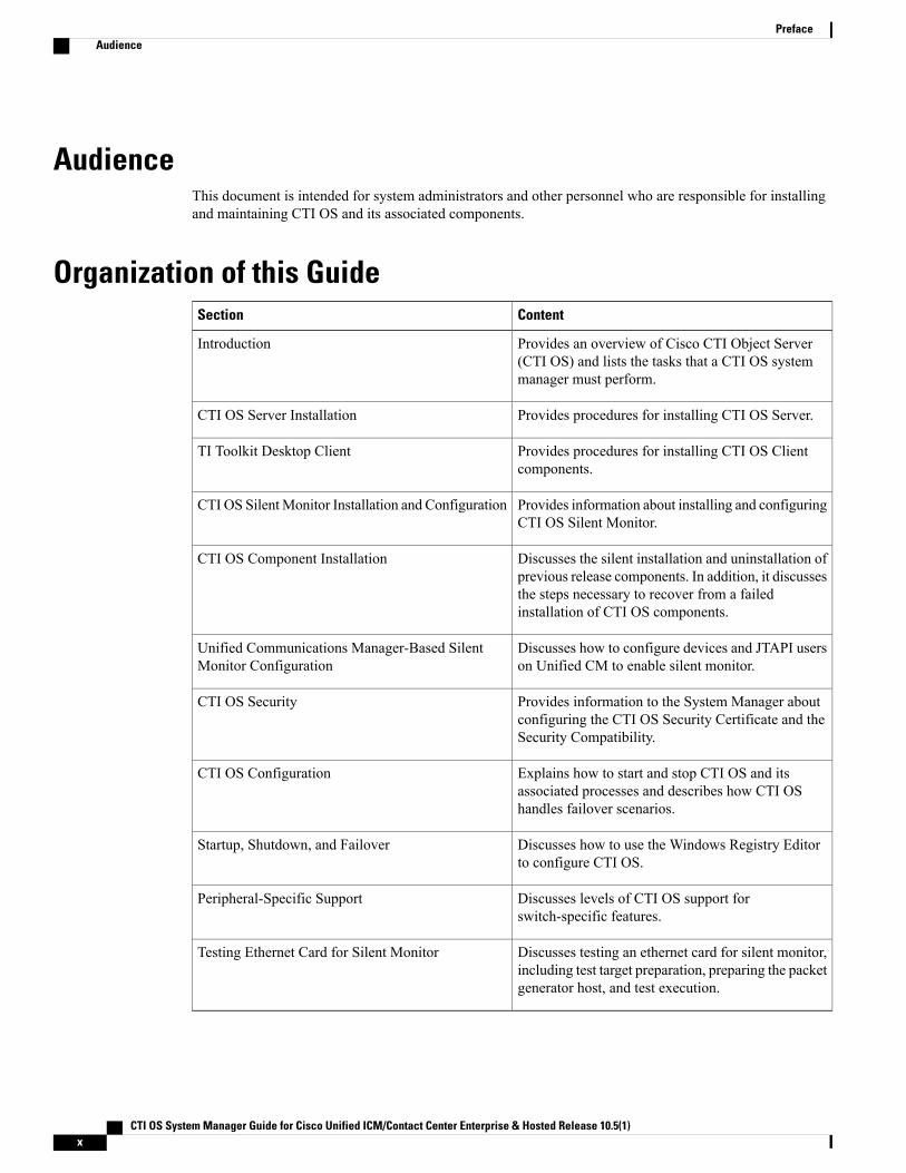
Organization of this GuideContentSection
Provides an overview of Cisco CTI Object Server(CTI OS) and lists the tasks that a CTI OS systemmanager must perform.
Introduction
Provides procedures for installing CTI OS Server.CTI OS Server Installation
Provides procedures for installing CTI OS Clientcomponents.
TI Toolkit Desktop Client
Provides information about installing and configuringCTI OS Silent Monitor.
CTI OS SilentMonitor Installation and Configuration
Discusses the silent installation and uninstallation ofprevious release components. In addition, it discussesthe steps necessary to recover from a failedinstallation of CTI OS components.
CTI OS Component Installation
Discusses how to configure devices and JTAPI userson Unified CM to enable silent monitor.
Unified Communications Manager-Based SilentMonitor Configuration
Provides information to the System Manager aboutconfiguring the CTI OS Security Certificate and theSecurity Compatibility.
CTI OS Security
Explains how to start and stop CTI OS and itsassociated processes and describes how CTI OShandles failover scenarios.
CTI OS Configuration
Discusses how to use the Windows Registry Editorto configure CTI OS.
Startup, Shutdown, and Failover
Discusses levels of CTI OS support forswitch-specific features.
Peripheral-Specific Support
Discusses testing an ethernet card for silent monitor,including test target preparation, preparing the packetgenerator host, and test execution.
Testing Ethernet Card for Silent Monitor
CTI OS System Manager Guide for Cisco Unified ICM/Contact Center Enterprise & Hosted Release 10.5(1)x
PrefaceAudience
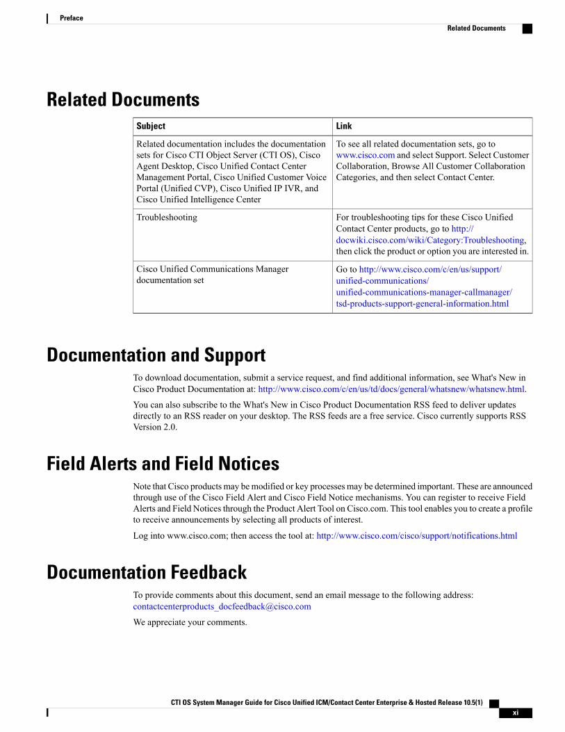
Related DocumentsLinkSubject
To see all related documentation sets, go towww.cisco.com and select Support. Select CustomerCollaboration, Browse All Customer CollaborationCategories, and then select Contact Center.
Related documentation includes the documentationsets for Cisco CTI Object Server (CTI OS), CiscoAgent Desktop, Cisco Unified Contact CenterManagement Portal, Cisco Unified Customer VoicePortal (Unified CVP), Cisco Unified IP IVR, andCisco Unified Intelligence Center
For troubleshooting tips for these Cisco UnifiedContact Center products, go to http://docwiki.cisco.com/wiki/Category:Troubleshooting,then click the product or option you are interested in.
Troubleshooting
Go to http://www.cisco.com/c/en/us/support/unified-communications/unified-communications-manager-callmanager/tsd-products-support-general-information.html
Cisco Unified Communications Managerdocumentation set
Documentation and SupportTo download documentation, submit a service request, and find additional information, see What's New inCisco Product Documentation at: http://www.cisco.com/c/en/us/td/docs/general/whatsnew/whatsnew.html.
You can also subscribe to the What's New in Cisco Product Documentation RSS feed to deliver updatesdirectly to an RSS reader on your desktop. The RSS feeds are a free service. Cisco currently supports RSSVersion 2.0.
Field Alerts and Field NoticesNote that Cisco products may bemodified or key processes may be determined important. These are announcedthrough use of the Cisco Field Alert and Cisco Field Notice mechanisms. You can register to receive FieldAlerts and Field Notices through the Product Alert Tool on Cisco.com. This tool enables you to create a profileto receive announcements by selecting all products of interest.
Log into www.cisco.com; then access the tool at: http://www.cisco.com/cisco/support/notifications.html
Documentation FeedbackTo provide comments about this document, send an email message to the following address:[email protected]
We appreciate your comments.
CTI OS System Manager Guide for Cisco Unified ICM/Contact Center Enterprise & Hosted Release 10.5(1) xi
PrefaceRelated Documents
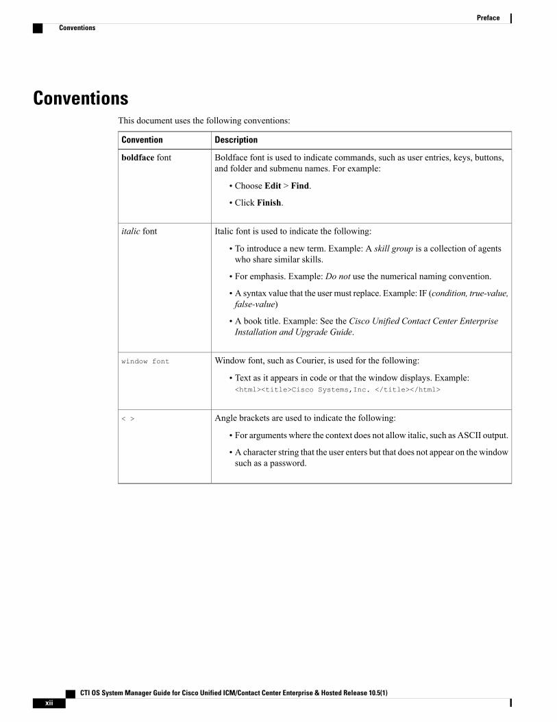
ConventionsThis document uses the following conventions:
DescriptionConvention
Boldface font is used to indicate commands, such as user entries, keys, buttons,and folder and submenu names. For example:
• Choose Edit > Find.
• Click Finish.
boldface font
Italic font is used to indicate the following:
• To introduce a new term. Example: A skill group is a collection of agentswho share similar skills.
• For emphasis. Example: Do not use the numerical naming convention.
• A syntax value that the user must replace. Example: IF (condition, true-value,false-value)
• A book title. Example: See the Cisco Unified Contact Center EnterpriseInstallation and Upgrade Guide.
italic font
Window font, such as Courier, is used for the following:
• Text as it appears in code or that the window displays. Example:<html><title>Cisco Systems,Inc. </title></html>
window font
Angle brackets are used to indicate the following:
• For arguments where the context does not allow italic, such as ASCII output.
• A character string that the user enters but that does not appear on the windowsuch as a password.
< >
CTI OS System Manager Guide for Cisco Unified ICM/Contact Center Enterprise & Hosted Release 10.5(1)xii
PrefaceConventions
C H A P T E R 1Introduction
This chapter provides an overview of Cisco CTI Object Server (CTI OS) and lists the tasks that a CTI OSsystem manager must perform:
• Overview of CTI OS, page 1
• System Manager Responsibilities, page 4
• System Requirements, page 4
• Silent monitoring, page 5
Overview of CTI OSThe CTI OS is the next generation customer contact integration platform from Cisco. CTI OS combines apowerful, feature-rich server and an object-oriented software development toolkit to enable rapid developmentand deployment of complex CTI applications. Together, the Cisco CTI Server Interface, CTI OS Server, and
CTI OS System Manager Guide for Cisco Unified ICM/Contact Center Enterprise & Hosted Release 10.5(1) 1
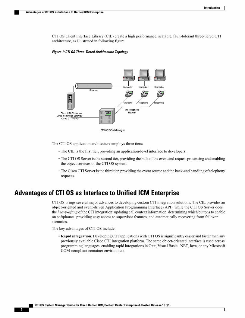
CTI OS Client Interface Library (CIL) create a high performance, scalable, fault-tolerant three-tiered CTIarchitecture, as illustrated in following figure.
Figure 1: CTI OS Three-Tiered Architecture Topology
The CTI OS application architecture employs three tiers:
• The CIL is the first tier, providing an application-level interface to developers.
• The CTI OS Server is the second tier, providing the bulk of the event and request processing and enablingthe object services of the CTI OS system.
• The Cisco CTI Server is the third tier, providing the event source and the back-end handling of telephonyrequests.
Advantages of CTI OS as Interface to Unified ICM EnterpriseCTI OS brings several major advances to developing custom CTI integration solutions. The CIL provides anobject-oriented and event-driven Application Programming Interface (API), while the CTI OS Server doesthe heavy-lifting of the CTI integration: updating call context information, determining which buttons to enableon softphones, providing easy access to supervisor features, and automatically recovering from failoverscenarios.
The key advantages of CTI OS include:
• Rapid integration. Developing CTI applications with CTI OS is significantly easier and faster than anypreviously available Cisco CTI integration platform. The same object-oriented interface is used acrossprogramming languages, enabling rapid integrations in C++, Visual Basic, .NET, Java, or anyMicrosoftCOM-compliant container environment.
CTI OS System Manager Guide for Cisco Unified ICM/Contact Center Enterprise & Hosted Release 10.5(1)2
IntroductionAdvantages of CTI OS as Interface to Unified ICM Enterprise
The inclusion of the .NET toolkit allows for custom applications to be written in C#,VB.NET, or any other CLR-compliant language. By starting with the code for the .NETsample, the CTI Toolkit Combo Desktop developers can quickly customize the codewithout having to start from scratch.
Note
CTI OS enables developers to create a screen-pop application in as little as five minutes. The onlycustom-development effort required is within the homegrown application to which CTI is being added.
• Complex solutions made simple. CTI OS enables complex server-to-server integrations and multipleagent monitoring-type applications. The CIL provides a single object-oriented interface that you canuse in two modes: agent mode and monitor mode. For more information about these two modes, seeCTI OS Developer Guide for Cisco Unified ICM/Contact Center Enterprise & Hosted. This documentis available at http://www.cisco.com/en/US/products/sw/custcosw/ps14/products_programming_reference_guides_list.html.
• Fault tolerant. CTI OS is built upon the Unified ICM Node Manager fault-tolerance platform, whichautomatically detects process failure and restarts the process, enabling work to continue. Upon recoveryfrom a failure, CTI OS initiates a complete, system-wide snapshot of all agents, calls, and supervisorsand propagates updates to all client-side objects.
Key Benefits of CTI OS for CTI Application DevelopersThe CTI OS CIL provides programmers with the tools required to rapidly develop high-quality CTI-enabledapplications, taking advantage of the rich features of the CTI OS Server. Every feature of CTI OSwas designedwith ease of integration in mind, to remove the traditional barriers to entry for CTI integrations:
• Object-oriented interactions. CTI OS provides an object-oriented CTI interface by defining objectsfor all call center interactions. Programmers interact directly with Session, Agent, SkillGroup, and Callobjects to perform all functions. CIL objects are thin proxies for the server-side objects, where all the'heavy-lifting' is done. The Session object manages all objects within the CIL. A UniqueObjectIDidentifies each object. Programmers can access an object by its UniqueObjectID or by iterating throughthe object collections.
• Connection and sessionmanagement. The CTI OSCIL provides out-of-the-box connection and sessionmanagement with the CTI OS Server, hiding all of the details of the TCP/IP sockets connection. TheCIL also provides out-of-the-box failover recovery. Upon recovery from a failure, the CIL automaticallyreconnects to another CTI OS Server (or reconnects to the same CTI OS Server after restart), reestablishesthe session, and recovers all objects for that session.
• All parameters are key-value pairs. The CTI OS CIL provides helper classes to treat all event andrequest parameters as simply a set of key-value pairs. All properties on the CTI OS objects are accessibleby name via a simple Value = GetValue(“key”) mechanism. Client programmers can add values of anytype to the CTI OS Arguments structure using the enumerated CTI OS keywords or their own stringkeywords (for example, AddItem[“DialedNumber”, “1234”]). This provides for future enhancement ofthe interface without requiring any changes to the method signatures.
• Simple event subscription model. The CTI OS CIL implements a publisher-subscriber design patternto enable easy subscription to event interfaces. Programmers can subscribe to the event interface thatsuits their needs, or use the AllInOne interface to subscribe to all events. Subclassable event adapter
CTI OS System Manager Guide for Cisco Unified ICM/Contact Center Enterprise & Hosted Release 10.5(1) 3
IntroductionKey Benefits of CTI OS for CTI Application Developers
classes enable programmers to subscribe to event interfaces and only add minimal custom code for theevents they use, and no code at all for events they do not use.
System Manager ResponsibilitiesThe remainder of this document provides step-by-step procedures for the tasks a systemmanager must performto set up and configure CTI OS. These tasks include:
• Installing CTI OS Server.
• InstallingCTI Toolkit Agent Desktop, Supervisor Desktop, Tools, Documentation, Win32 SDK, JavaSDK, and .NET SDK.
You can skip the procedures discussed in Chapters 2 and 3 if you already have CTI OS Release 8.5(3) orthe later Service Releases (SRs) installed on your system.
Note
• Enabling CTI OS security.
• Using the Windows Registry Editor (regedit.exe) to configure the required CTI OS registry keys.
• Starting CTI OS and its associated processes from Unified CCE Service Control.
You must have administrator privileges to perform the procedures discussed in this manual.Note
Related Topics
CTI OS Server Installation, on page 13CTI Toolkit Desktop Client Installation, on page 31CTI OS Silent Monitor Installation and Configuration, on page 47CTI OS Security, on page 77CTI OS Configuration, on page 85Startup, Shutdown, and Failover, on page 121
System RequirementsSee the Design Guide for a quick reference on configuration limits and scalability constraints. For moreinformation on system requirements, seeVirtualization for Unified CCE and the Compatibility Matrix forUnified CCE pages on the DocWiki,
Set User PrivilegesOn Windows Server 2008 R2 operating systems, users must have privileges that enables them to run legacyapplications and have read/write access to the Cisco registry keys that the desktop applications use. To set
CTI OS System Manager Guide for Cisco Unified ICM/Contact Center Enterprise & Hosted Release 10.5(1)4
IntroductionSystem Manager Responsibilities
user privileges to enable users to run CTI OSAgent Desktop and CTI OS Supervisor Desktop, an administratormust perform the following steps.
Procedure
Step 1 On the Microsoft Windows Start Menu, select Start > Run.Step 2 Type in regedt32 and click OK.
The Microsoft Windows Registry Editor window appears.
Step 3 Go to the following registry location:HKEY_LOCAL_MACHINE\SOFTWARE\Cisco Systems, Inc.\CTI Desktop\Ctios
Step 4 Select Security > Permissions.A Permissions dialog box appears.
Step 5 If you are adding a new user, perform the following steps.a) Click Add.
A Select Users dialog box appears.
b) Select the user to be added from the list in the top half of the Select Users dialog box.c) Click Add, then click OK.
You return to the Permissions dialog box; the user you just added is now on the list.
Step 6 Click the user whose privileges you want to set.Step 7 Set the Full Control permissions for this user to Allow.Step 8 Click Apply.Step 9 Click OK.Step 10 Exit Registry Editor.
Silent monitoringSilent monitoring is a feature that allows a supervisor to eavesdrop on a conversation between an agent anda customer without allowing the agent to detect the monitoring session. Silent monitoring functionality canbe provided by Cisco Unified Communications Manager (Unified CM) or CTI OS.
You can configure each CTI OS Server for either Unified CM-based or CTI OS-based silent monitoring.
Silent Monitor Differences Between Unified CM and CTI OSBesides the differences in implementation, CTI OS and Unified CM also differ in when they can be invokedand when they end.
CTI OS System Manager Guide for Cisco Unified ICM/Contact Center Enterprise & Hosted Release 10.5(1) 5
IntroductionSilent monitoring
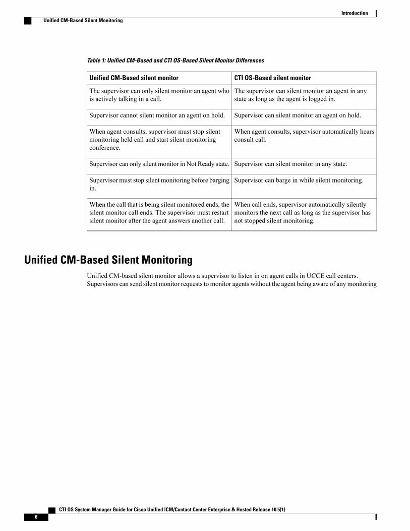
Table 1: Unified CM-Based and CTI OS-Based Silent Monitor Differences
CTI OS-Based silent monitorUnified CM-Based silent monitor
The supervisor can silent monitor an agent in anystate as long as the agent is logged in.
The supervisor can only silent monitor an agent whois actively talking in a call.
Supervisor can silent monitor an agent on hold.Supervisor cannot silent monitor an agent on hold.
When agent consults, supervisor automatically hearsconsult call.
When agent consults, supervisor must stop silentmonitoring held call and start silent monitoringconference.
Supervisor can silent monitor in any state.Supervisor can only silent monitor in Not Ready state.
Supervisor can barge in while silent monitoring.Supervisor must stop silent monitoring before bargingin.
When call ends, supervisor automatically silentlymonitors the next call as long as the supervisor hasnot stopped silent monitoring.
When the call that is being silent monitored ends, thesilent monitor call ends. The supervisor must restartsilent monitor after the agent answers another call.
Unified CM-Based Silent MonitoringUnified CM-based silent monitor allows a supervisor to listen in on agent calls in UCCE call centers.Supervisors can send silent monitor requests to monitor agents without the agent being aware of anymonitoring
CTI OS System Manager Guide for Cisco Unified ICM/Contact Center Enterprise & Hosted Release 10.5(1)6
IntroductionUnified CM-Based Silent Monitoring
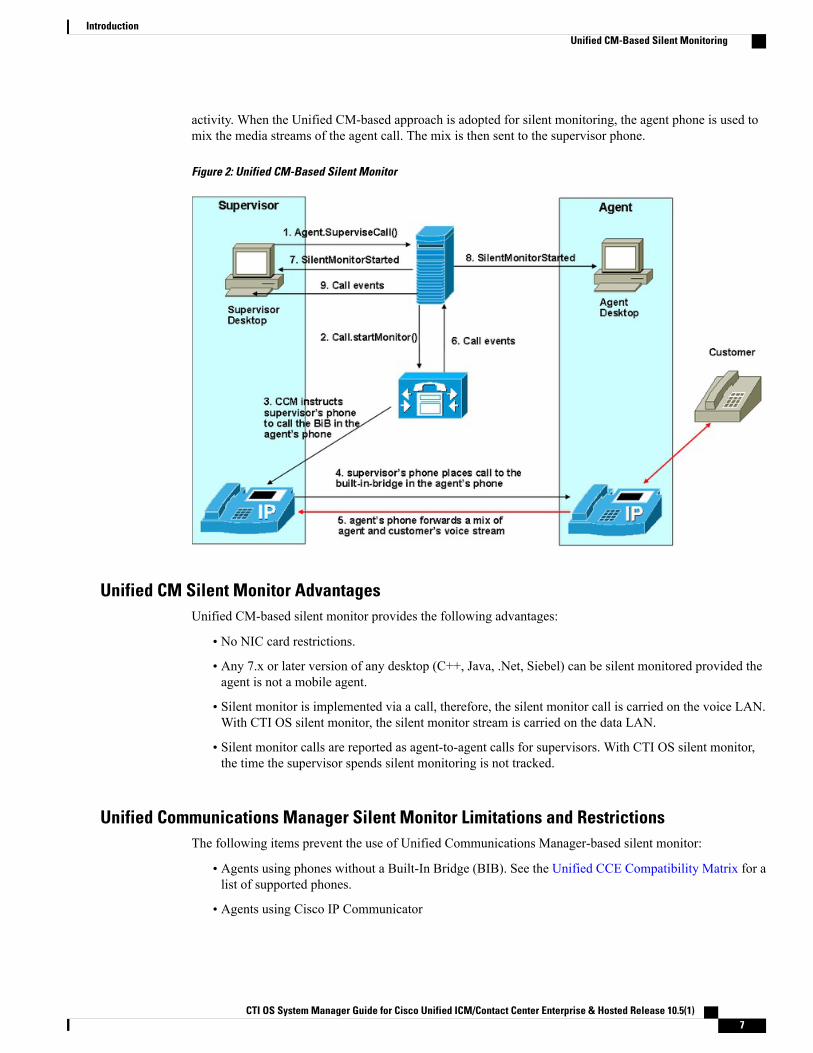
activity. When the Unified CM-based approach is adopted for silent monitoring, the agent phone is used tomix the media streams of the agent call. The mix is then sent to the supervisor phone.
Figure 2: Unified CM-Based Silent Monitor
Unified CM Silent Monitor AdvantagesUnified CM-based silent monitor provides the following advantages:
• No NIC card restrictions.
• Any 7.x or later version of any desktop (C++, Java, .Net, Siebel) can be silent monitored provided theagent is not a mobile agent.
• Silent monitor is implemented via a call, therefore, the silent monitor call is carried on the voice LAN.With CTI OS silent monitor, the silent monitor stream is carried on the data LAN.
• Silent monitor calls are reported as agent-to-agent calls for supervisors. With CTI OS silent monitor,the time the supervisor spends silent monitoring is not tracked.
Unified Communications Manager Silent Monitor Limitations and RestrictionsThe following items prevent the use of Unified Communications Manager-based silent monitor:
• Agents using phones without a Built-In Bridge (BIB). See the Unified CCE Compatibility Matrix for alist of supported phones.
• Agents using Cisco IP Communicator
CTI OS System Manager Guide for Cisco Unified ICM/Contact Center Enterprise & Hosted Release 10.5(1) 7
IntroductionUnified CM-Based Silent Monitoring
• Supervisors using 7.1(x) or earlier desktops
• Silent monitoring SRTP streams is not supported
• Mobile agents cannot use this method of silent monitoring
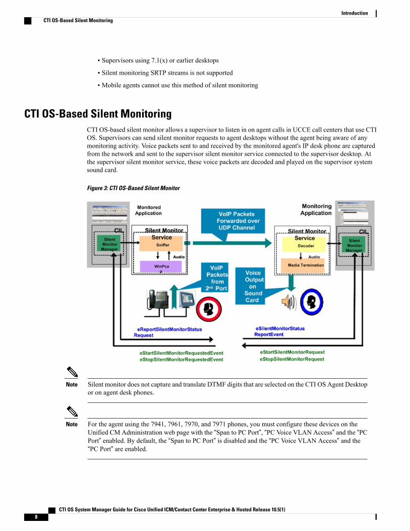
CTI OS-Based Silent MonitoringCTI OS-based silent monitor allows a supervisor to listen in on agent calls in UCCE call centers that use CTIOS. Supervisors can send silent monitor requests to agent desktops without the agent being aware of anymonitoring activity. Voice packets sent to and received by the monitored agent's IP desk phone are capturedfrom the network and sent to the supervisor silent monitor service connected to the supervisor desktop. Atthe supervisor silent monitor service, these voice packets are decoded and played on the supervisor systemsound card.
Figure 3: CTI OS-Based Silent Monitor
Silent monitor does not capture and translate DTMF digits that are selected on the CTI OS Agent Desktopor on agent desk phones.
Note
For the agent using the 7941, 7961, 7970, and 7971 phones, you must configure these devices on theUnified CM Administration web page with the “Span to PC Port”, “PC Voice VLAN Access” and the “PCPort” enabled. By default, the “Span to PC Port” is disabled and the “PC Voice VLAN Access” and the“PC Port” are enabled.
Note
CTI OS System Manager Guide for Cisco Unified ICM/Contact Center Enterprise & Hosted Release 10.5(1)8
IntroductionCTI OS-Based Silent Monitoring
Network Topology for Silent Monitoring
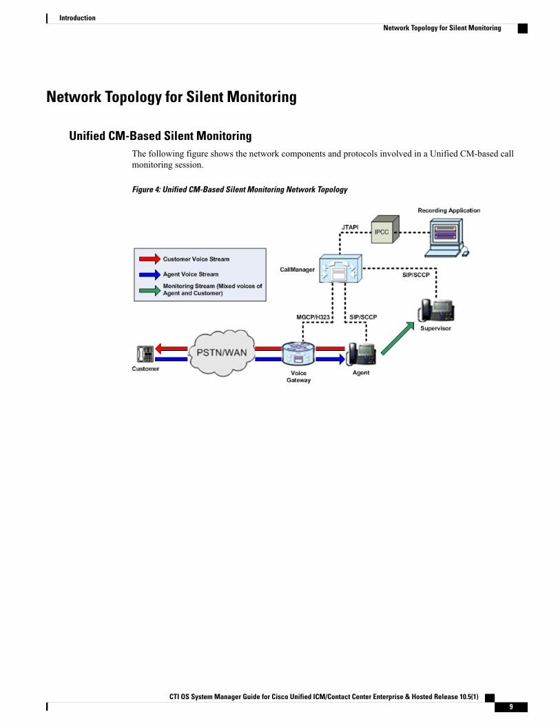
Unified CM-Based Silent MonitoringThe following figure shows the network components and protocols involved in a Unified CM-based callmonitoring session.
Figure 4: Unified CM-Based Silent Monitoring Network Topology
CTI OS System Manager Guide for Cisco Unified ICM/Contact Center Enterprise & Hosted Release 10.5(1) 9
IntroductionNetwork Topology for Silent Monitoring
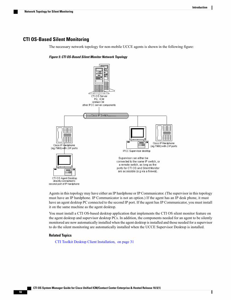
CTI OS-Based Silent MonitoringThe necessary network topology for non-mobile UCCE agents is shown in the following figure:
Figure 5: CTI OS-Based Silent Monitor Network Topology
Agents in this topologymay have either an IP hardphone or IP Communicator. (The supervisor in this topologymust have an IP hardphone. IP Communicator is not an option.) If the agent has an IP desk phone, it musthave an agent desktop PC connected to the second IP port. If the agent has IP Communicator, you must installit on the same machine as the agent desktop.
You must install a CTI OS-based desktop application that implements the CTI OS silent monitor feature onthe agent desktop and supervisor desktop PCs. In addition, the components needed for an agent to be silentlymonitored are now automatically installed when the agent desktop is installed and those needed for a supervisorto do the silent monitoring are automatically installed when the UCCE Supervisor Desktop is installed.
Related Topics
CTI Toolkit Desktop Client Installation, on page 31
CTI OS System Manager Guide for Cisco Unified ICM/Contact Center Enterprise & Hosted Release 10.5(1)10
IntroductionNetwork Topology for Silent Monitoring
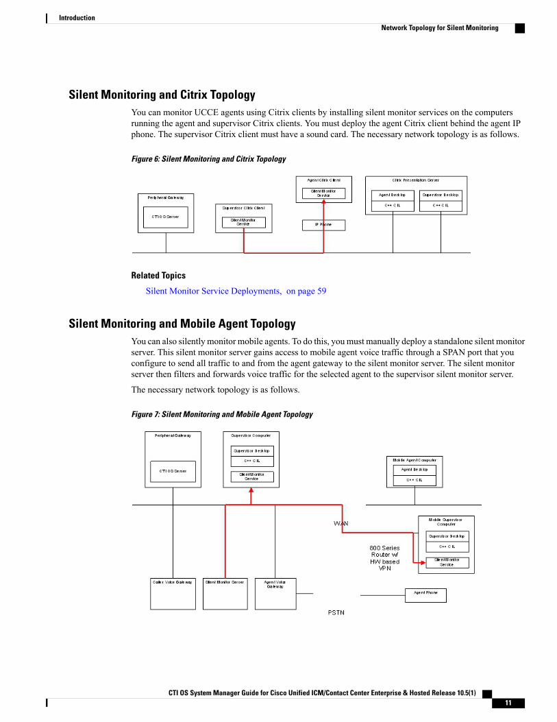
Silent Monitoring and Citrix TopologyYou can monitor UCCE agents using Citrix clients by installing silent monitor services on the computersrunning the agent and supervisor Citrix clients. You must deploy the agent Citrix client behind the agent IPphone. The supervisor Citrix client must have a sound card. The necessary network topology is as follows.
Figure 6: Silent Monitoring and Citrix Topology
Related Topics
Silent Monitor Service Deployments, on page 59
Silent Monitoring and Mobile Agent TopologyYou can also silently monitor mobile agents. To do this, you must manually deploy a standalone silent monitorserver. This silent monitor server gains access to mobile agent voice traffic through a SPAN port that youconfigure to send all traffic to and from the agent gateway to the silent monitor server. The silent monitorserver then filters and forwards voice traffic for the selected agent to the supervisor silent monitor server.
The necessary network topology is as follows.
Figure 7: Silent Monitoring and Mobile Agent Topology
CTI OS System Manager Guide for Cisco Unified ICM/Contact Center Enterprise & Hosted Release 10.5(1) 11
IntroductionNetwork Topology for Silent Monitoring
Related Topics
Silent Monitor Service Deployments, on page 59
Calculation of Additional Needed BandwidthSilent monitoring of an agent consumes almost the same network bandwidth as an additional voice call. If asingle agent requires bandwidth for one voice call, then the same agent being silent monitored requiresbandwidth for two concurrent voice calls.
For example, assume the following:
• You have 100 concurrent agents on your network.
• Up to 20% of the agents are monitored at any given time.
In this case, plan for network capacity for 100 + (20% of 100) concurrent calls, or 120 concurrent calls.
To calculate the total network bandwidth required for your call load, you would then multiply this number ofcalls by the per-call bandwidth figure for your particular codec and network protocol.
For example, the table on the Cisco Voice Over IP-Per Call Bandwidth Consumption website lists the per-callbandwidth on the G.711 codec (for a call with the default voice payload size) over Ethernet as 87.2 Kbps.You multiply this 87.2 Kbps by 120 calls to obtain the total required network bandwidth.
For more information about per-call bandwidths for various codecs and network protocols, see the CiscoVoice Over IP-Per Call Bandwidth Consumption website at
http://www.cisco.com/c/en/us/support/docs/voice/voice-quality/7934-bwidth-consume.html.
For more information about calculating bandwidth, see the Cisco Voice Codec Bandwidth Calculator at http://tools.cisco.com/Support/VBC/jsp/Codec_Calc1.jsp.
CTI OS System Manager Guide for Cisco Unified ICM/Contact Center Enterprise & Hosted Release 10.5(1)12
IntroductionNetwork Topology for Silent Monitoring
C H A P T E R 2CTI OS Server Installation
This chapter lists some guidelines to consider when you install the CTI OS Server and provides proceduresfor these tasks.
You cannot run the installer remotely. Mount the installer ISO file only to a local machine. Various errorscan occur during installation over the network. Keep in mind that for installation of major releases, thereis no way to roll the installation back to the previous release if the installation or upgrade fails part waythrough.
Caution
• CTI OS Server Installation Guidelines, page 13
• Upgrade from Previous Version, page 14
• Install CTI OS Server, page 14
• Uninstalling CTI OS Server, page 26
• Determine Version Number of Installed Files, page 27
CTI OS Server Installation GuidelinesFollowing are some guidelines to consider when you install CTI OS Server:
• CTI OS is typically installed in a duplex configuration. Two CTI OS Servers installed on separate systemswork in parallel to provide redundancy. Installing only one CTI OS Server prevents failover recoveryby client systems.
• CTI OS must be co-located on the same box as the PG/CG.
• Ensure that your CTI OS systemmeets the specified requirements. See CompatibilityMatrix for UnifiedCCE.
Related Topics
Startup, Shutdown, and Failover, on page 121
CTI OS System Manager Guide for Cisco Unified ICM/Contact Center Enterprise & Hosted Release 10.5(1) 13
Upgrade from Previous VersionIf you are upgrading from a CTI OS Server Release 10.0 you do not need to uninstall CTI OS Server beforeyou install CTI OS Server Release 10.5.
The listen ports for CTI OS Server and silent monitor are registered as firewall exceptions upon installationof CTI OS Sever 10.(x).
Note
Procedure
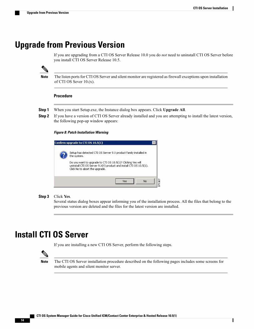
Step 1 When you start Setup.exe, the Instance dialog box appears. Click Upgrade All.Step 2 If you have a version of CTI OS Server already installed and you are attempting to install the latest version,
the following pop-up window appears:
Figure 8: Patch Installation Warning
Step 3 Click Yes.Several status dialog boxes appear informing you of the installation process. All the files that belong to theprevious version are deleted and the files for the latest version are installed.
Install CTI OS ServerIf you are installing a new CTI OS Server, perform the following steps.
The CTI OS Server installation procedure described on the following pages includes some screens formobile agents and silent monitor server.
Note
CTI OS System Manager Guide for Cisco Unified ICM/Contact Center Enterprise & Hosted Release 10.5(1)14
CTI OS Server InstallationUpgrade from Previous Version
Procedure
Step 1 From the Server directory on the CD, run setup.exe.When you run programs from aWindows Server 2008 R2 systemwith User Account Control enabled,Windows needs your permission to continue. Click Allow in the User Account Control window torun the programs.
Note
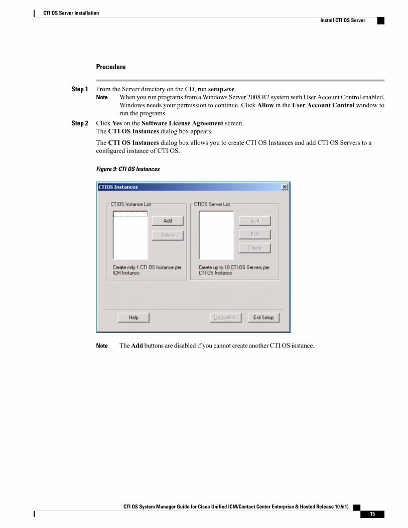
Step 2 Click Yes on the Software License Agreement screen.The CTI OS Instances dialog box appears.
The CTI OS Instances dialog box allows you to create CTI OS Instances and add CTI OS Servers to aconfigured instance of CTI OS.
Figure 9: CTI OS Instances
TheAdd buttons are disabled if you cannot create another CTI OS instance.Note
CTI OS System Manager Guide for Cisco Unified ICM/Contact Center Enterprise & Hosted Release 10.5(1) 15
CTI OS Server InstallationInstall CTI OS Server
Step 3 You must install a Windows Server 2008 R2 compatible maintenance release for this software to function onWindows Server 2008 R2.
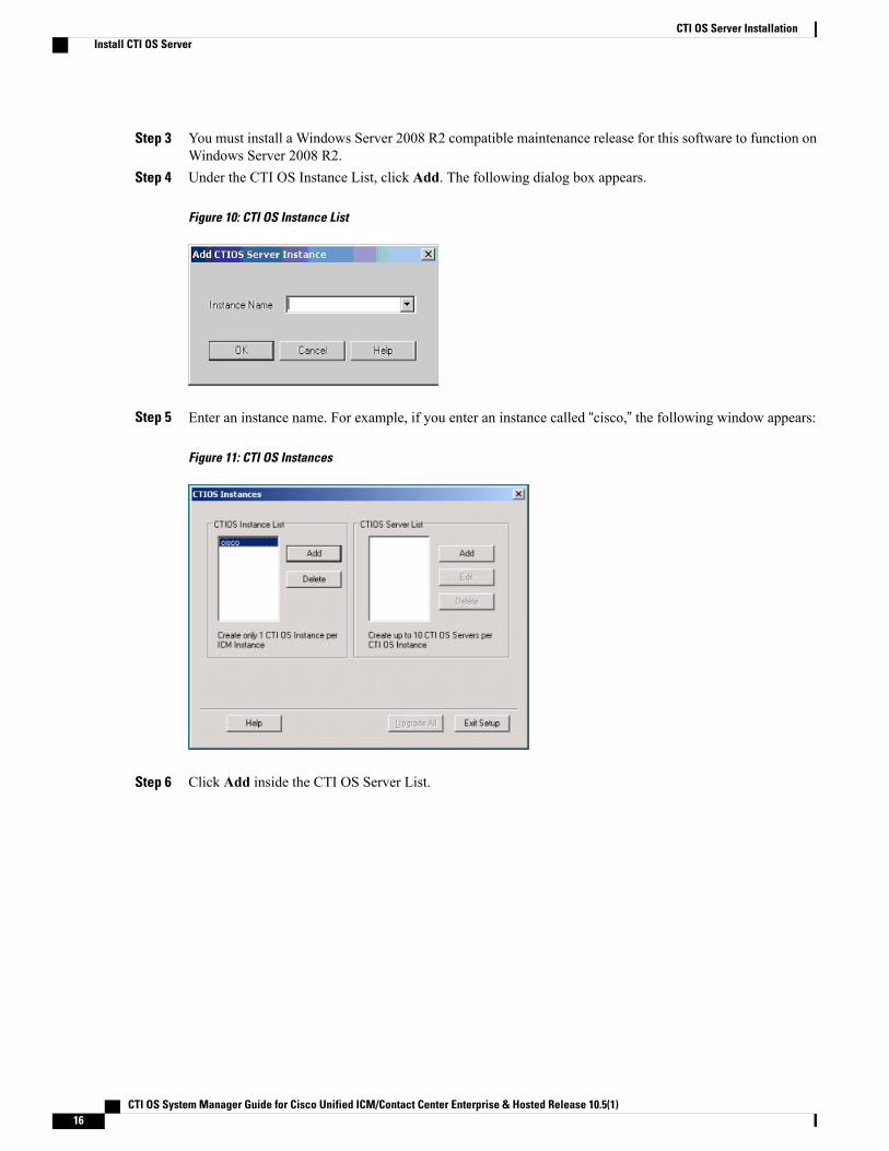
Step 4 Under the CTI OS Instance List, click Add. The following dialog box appears.
Figure 10: CTI OS Instance List
Step 5 Enter an instance name. For example, if you enter an instance called “cisco,” the following window appears:
Figure 11: CTI OS Instances
Step 6 Click Add inside the CTI OS Server List.
CTI OS System Manager Guide for Cisco Unified ICM/Contact Center Enterprise & Hosted Release 10.5(1)16
CTI OS Server InstallationInstall CTI OS Server
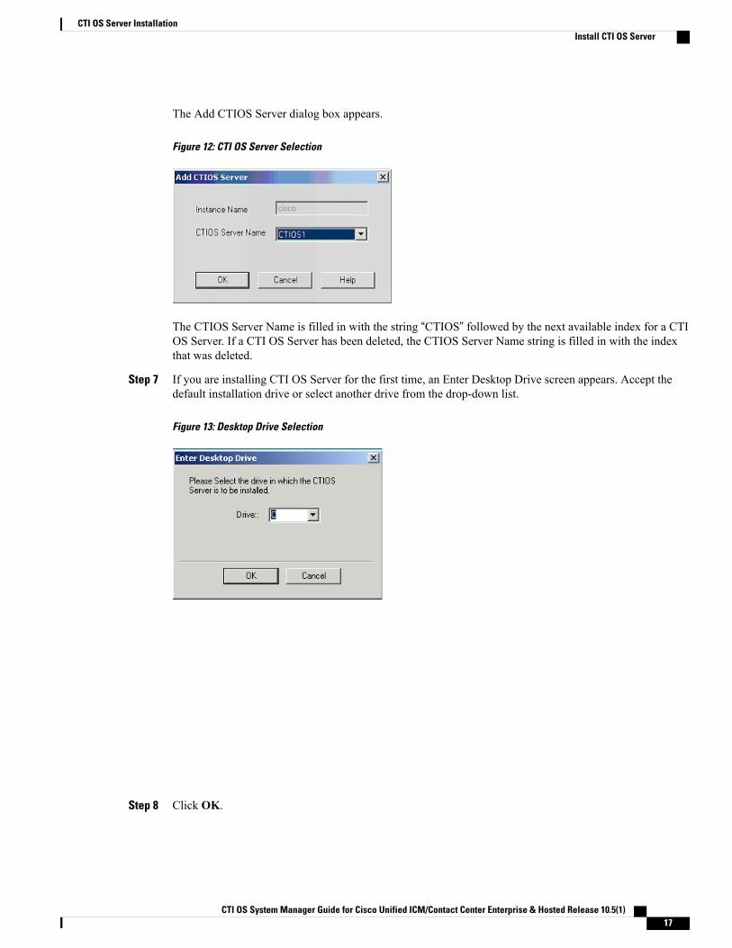
The Add CTIOS Server dialog box appears.
Figure 12: CTI OS Server Selection
The CTIOS Server Name is filled in with the string “CTIOS” followed by the next available index for a CTIOS Server. If a CTI OS Server has been deleted, the CTIOS Server Name string is filled in with the indexthat was deleted.
Step 7 If you are installing CTI OS Server for the first time, an Enter Desktop Drive screen appears. Accept thedefault installation drive or select another drive from the drop-down list.
Figure 13: Desktop Drive Selection
Step 8 Click OK.
CTI OS System Manager Guide for Cisco Unified ICM/Contact Center Enterprise & Hosted Release 10.5(1) 17
CTI OS Server InstallationInstall CTI OS Server
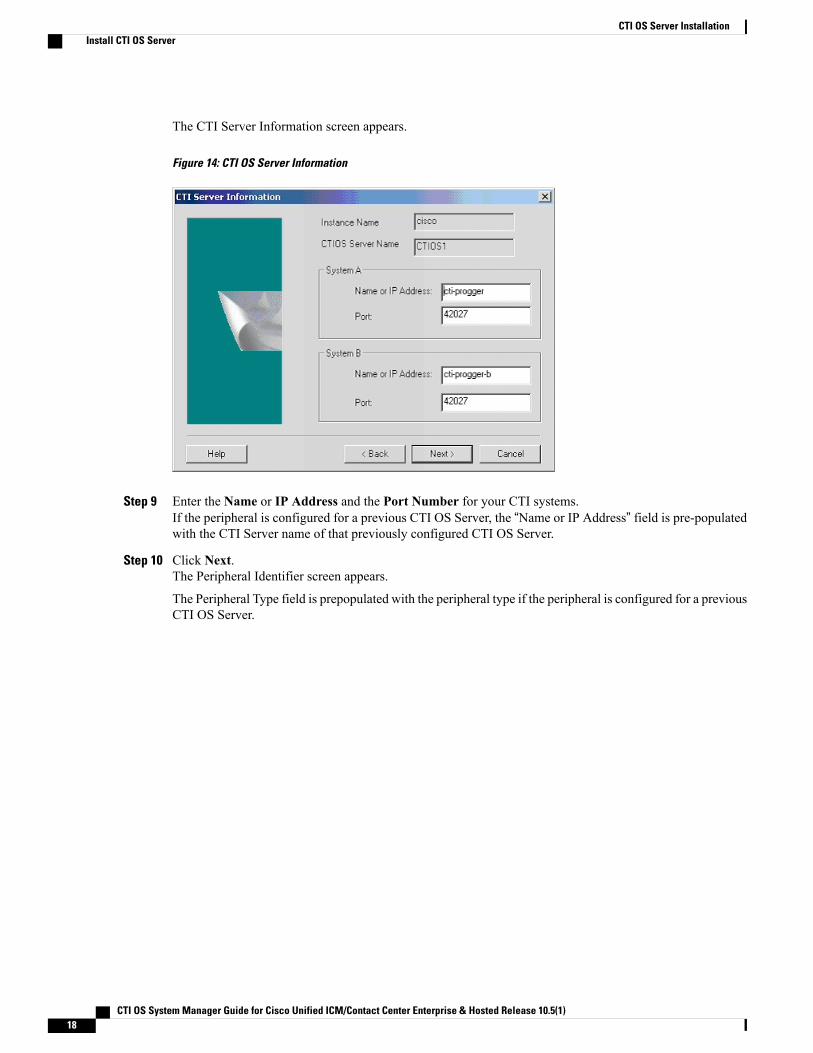
The CTI Server Information screen appears.
Figure 14: CTI OS Server Information
Step 9 Enter the Name or IP Address and the Port Number for your CTI systems.If the peripheral is configured for a previous CTI OS Server, the “Name or IP Address” field is pre-populatedwith the CTI Server name of that previously configured CTI OS Server.
Step 10 Click Next.The Peripheral Identifier screen appears.
The Peripheral Type field is prepopulated with the peripheral type if the peripheral is configured for a previousCTI OS Server.
CTI OS System Manager Guide for Cisco Unified ICM/Contact Center Enterprise & Hosted Release 10.5(1)18
CTI OS Server InstallationInstall CTI OS Server
When you configure multiple CTI OS Servers to use a single CTI Server, every CTI OS Serverconfigured in addition to the first defaults to the configuration of the first CTI OS Server.
Note
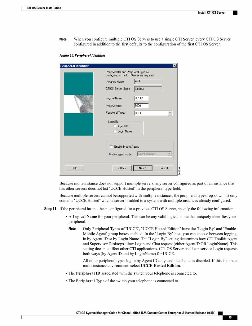
Figure 15: Peripheral Identifier
Because multi-instance does not support multiple servers, any server configured as part of an instance thathas other servers does not list “UCCE Hosted” in the peripheral type field.Because multiple servers cannot be supported with multiple instances, the peripheral type drop-down list onlycontains “UCCE Hosted” when a server is added to a system with multiple instances already configured.
Step 11 If the peripheral has not been configured for a previous CTI OS Server, specify the following information:
• A Logical Name for your peripheral. This can be any valid logical name that uniquely identifies yourperipheral.
Only Peripheral Types of “UCCE”, “UCCE Hosted Edition” have the “Login By” and “EnableMobile Agent” group boxes enabled. In the “Login By” box, you can choose between loggingin by Agent ID or by Login Name. The “Login By” setting determines how CTI Toolkit Agentand Supervisor Desktops allow Login and Chat request (either AgentID OR LoginName). Thissetting does not affect other CTI applications. CTI OS Server itself can service Login requestsboth ways (by AgentID and by LoginName) for UCCE.
All other peripheral types log in by Agent ID only, and the choice is disabled. If this is to be amulti-instance environment, select UCCE Hosted Edition.
Note
• The Peripheral ID associated with the switch your telephone is connected to.
• The Peripheral Type of the switch your telephone is connected to.
CTI OS System Manager Guide for Cisco Unified ICM/Contact Center Enterprise & Hosted Release 10.5(1) 19
CTI OS Server InstallationInstall CTI OS Server
•Whether to enable mobile agent.
• Mobile agent mode. Specify one of the following:
◦Agent chooses—Agent chooses the mode.
◦Call by call—The agent's remote phone is dialed for each individual call.
◦Nailed connection—The agent is called once upon login and remains connected.
You can specify information for only one peripheral during CTI OS Server setup. To configureadditional peripherals, follow the procedure in the section Configure Additional Peripherals, on page118.
Note
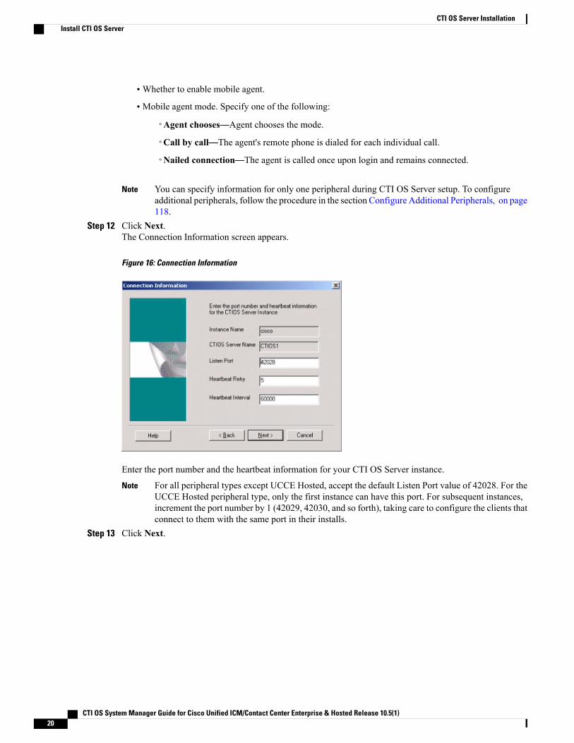
Step 12 Click Next.The Connection Information screen appears.
Figure 16: Connection Information
Enter the port number and the heartbeat information for your CTI OS Server instance.
For all peripheral types except UCCE Hosted, accept the default Listen Port value of 42028. For theUCCE Hosted peripheral type, only the first instance can have this port. For subsequent instances,increment the port number by 1 (42029, 42030, and so forth), taking care to configure the clients thatconnect to them with the same port in their installs.
Note
Step 13 Click Next.
CTI OS System Manager Guide for Cisco Unified ICM/Contact Center Enterprise & Hosted Release 10.5(1)20
CTI OS Server InstallationInstall CTI OS Server
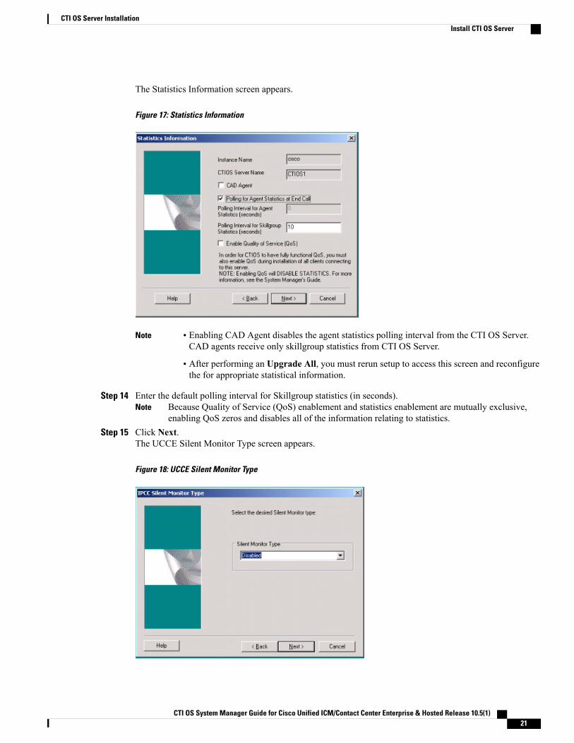
The Statistics Information screen appears.
Figure 17: Statistics Information
Note • Enabling CAD Agent disables the agent statistics polling interval from the CTI OS Server.CAD agents receive only skillgroup statistics from CTI OS Server.
• After performing an Upgrade All, you must rerun setup to access this screen and reconfigurethe for appropriate statistical information.
Step 14 Enter the default polling interval for Skillgroup statistics (in seconds).Because Quality of Service (QoS) enablement and statistics enablement are mutually exclusive,enabling QoS zeros and disables all of the information relating to statistics.
Note
Step 15 Click Next.The UCCE Silent Monitor Type screen appears.
Figure 18: UCCE Silent Monitor Type
CTI OS System Manager Guide for Cisco Unified ICM/Contact Center Enterprise & Hosted Release 10.5(1) 21
CTI OS Server InstallationInstall CTI OS Server
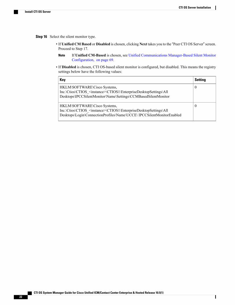
Step 16 Select the silent monitor type.
• IfUnified CMBased orDisabled is chosen, clickingNext takes you to the “Peer CTI OS Server” screen.Proceed to Step 17.
If Unified CM-Based is chosen, see Unified Communications Manager-Based Silent MonitorConfiguration, on page 69.
Note
• If Disabled is chosen, CTI OS-based silent monitor is configured, but disabled. This means the registrysettings below have the following values:
SettingKey
0HKLM\SOFTWARE\Cisco Systems,Inc.\Ctios\CTIOS_<instance>\CTIOS1\EnterpriseDesktopSettings\AllDesktops\IPCCSilentMonitor\Name\Settings\CCMBasedSilentMonitor
0HKLM\SOFTWARE\Cisco Systems,Inc.\Ctios\CTIOS_<instance>\CTIOS1\EnterpriseDesktopSettings\AllDesktops\Login\ConnectionProfiles\Name\UCCE\ IPCCSilentMonitorEnabled
CTI OS System Manager Guide for Cisco Unified ICM/Contact Center Enterprise & Hosted Release 10.5(1)22
CTI OS Server InstallationInstall CTI OS Server
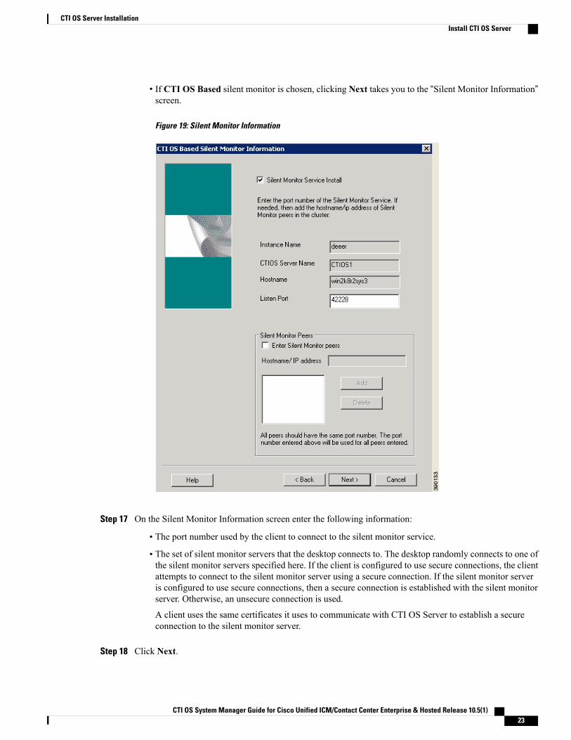
• If CTI OS Based silent monitor is chosen, clicking Next takes you to the “Silent Monitor Information”screen.
Figure 19: Silent Monitor Information
Step 17 On the Silent Monitor Information screen enter the following information:
• The port number used by the client to connect to the silent monitor service.
• The set of silent monitor servers that the desktop connects to. The desktop randomly connects to one ofthe silent monitor servers specified here. If the client is configured to use secure connections, the clientattempts to connect to the silent monitor server using a secure connection. If the silent monitor serveris configured to use secure connections, then a secure connection is established with the silent monitorserver. Otherwise, an unsecure connection is used.
A client uses the same certificates it uses to communicate with CTI OS Server to establish a secureconnection to the silent monitor server.
Step 18 Click Next.
CTI OS System Manager Guide for Cisco Unified ICM/Contact Center Enterprise & Hosted Release 10.5(1) 23
CTI OS Server InstallationInstall CTI OS Server
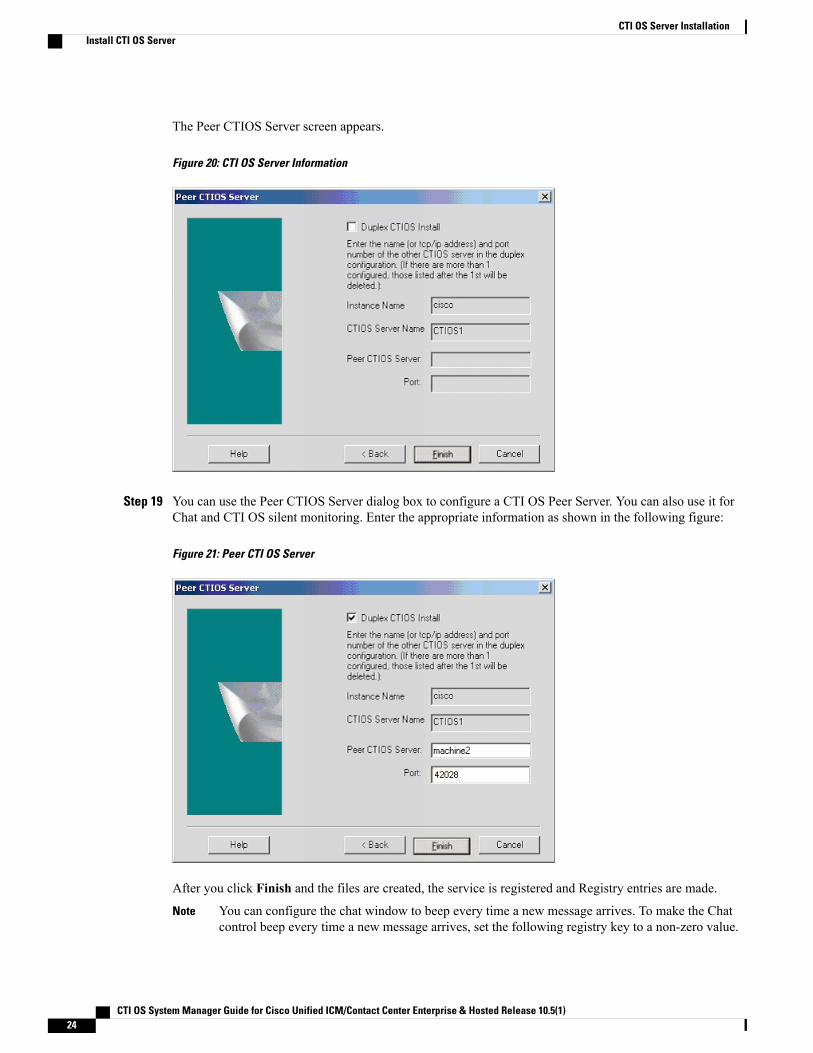
The Peer CTIOS Server screen appears.
Figure 20: CTI OS Server Information
Step 19 You can use the Peer CTIOS Server dialog box to configure a CTI OS Peer Server. You can also use it forChat and CTI OS silent monitoring. Enter the appropriate information as shown in the following figure:
Figure 21: Peer CTI OS Server
After you click Finish and the files are created, the service is registered and Registry entries are made.
You can configure the chat window to beep every time a new message arrives. To make the Chatcontrol beep every time a new message arrives, set the following registry key to a non-zero value.
Note
CTI OS System Manager Guide for Cisco Unified ICM/Contact Center Enterprise & Hosted Release 10.5(1)24
CTI OS Server InstallationInstall CTI OS Server
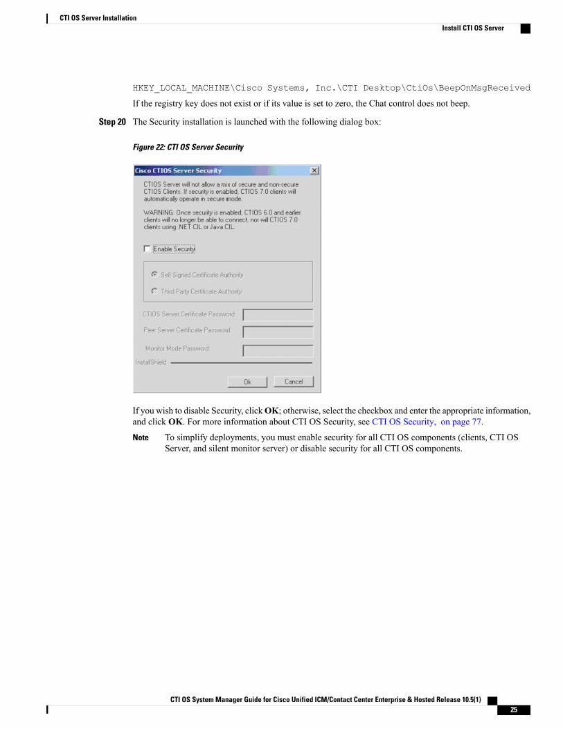
HKEY_LOCAL_MACHINE\Cisco Systems, Inc.\CTI Desktop\CtiOs\BeepOnMsgReceived
If the registry key does not exist or if its value is set to zero, the Chat control does not beep.
Step 20 The Security installation is launched with the following dialog box:
Figure 22: CTI OS Server Security
If you wish to disable Security, clickOK; otherwise, select the checkbox and enter the appropriate information,and click OK. For more information about CTI OS Security, see CTI OS Security, on page 77.
To simplify deployments, you must enable security for all CTI OS components (clients, CTI OSServer, and silent monitor server) or disable security for all CTI OS components.
Note
CTI OS System Manager Guide for Cisco Unified ICM/Contact Center Enterprise & Hosted Release 10.5(1) 25
CTI OS Server InstallationInstall CTI OS Server
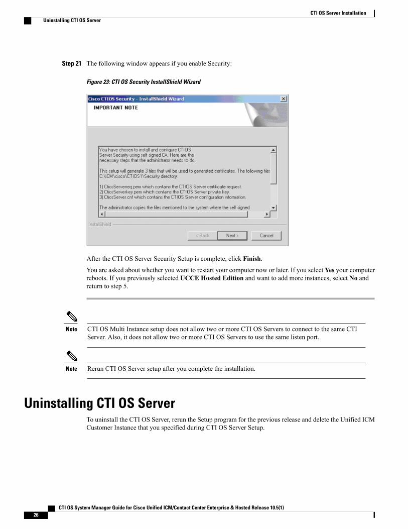
Step 21 The following window appears if you enable Security:
Figure 23: CTI OS Security InstallShield Wizard
After the CTI OS Server Security Setup is complete, click Finish.
You are asked about whether you want to restart your computer now or later. If you select Yes your computerreboots. If you previously selected UCCE Hosted Edition and want to add more instances, select No andreturn to step 5.
CTI OS Multi Instance setup does not allow two or more CTI OS Servers to connect to the same CTIServer. Also, it does not allow two or more CTI OS Servers to use the same listen port.
Note
Rerun CTI OS Server setup after you complete the installation.Note
Uninstalling CTI OS ServerTo uninstall the CTI OS Server, rerun the Setup program for the previous release and delete the Unified ICMCustomer Instance that you specified during CTI OS Server Setup.
CTI OS System Manager Guide for Cisco Unified ICM/Contact Center Enterprise & Hosted Release 10.5(1)26
CTI OS Server InstallationUninstalling CTI OS Server
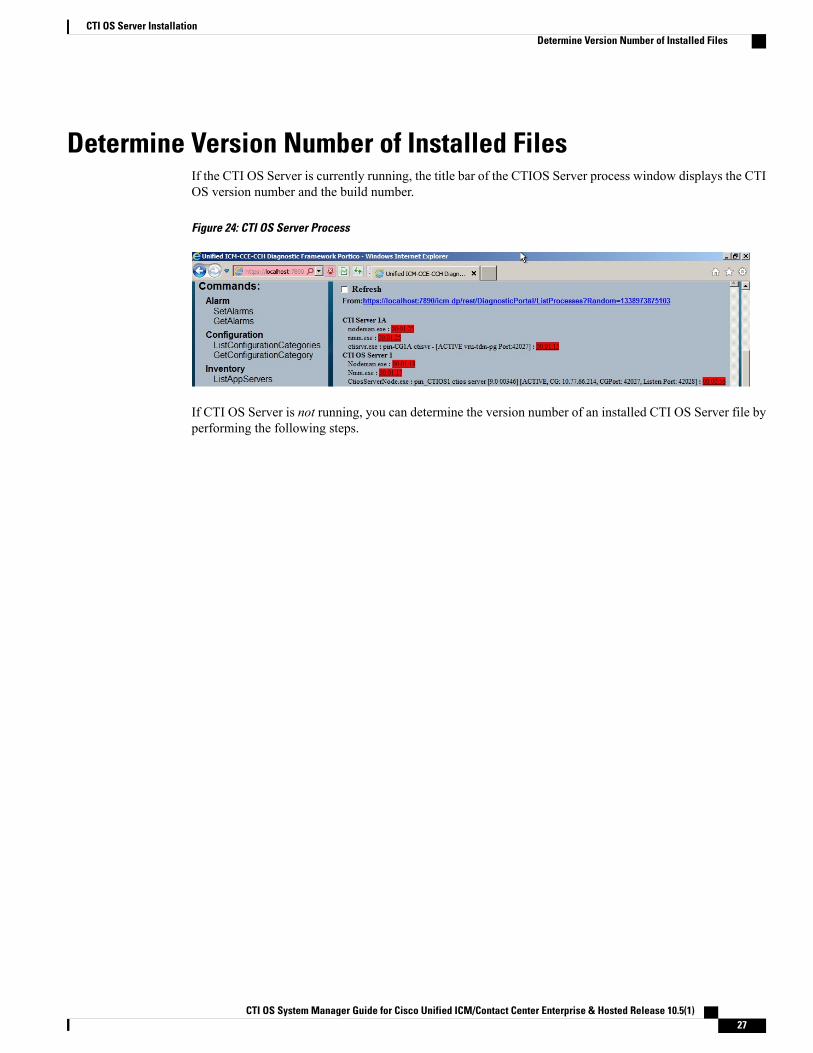
Determine Version Number of Installed FilesIf the CTI OS Server is currently running, the title bar of the CTIOS Server process window displays the CTIOS version number and the build number.
Figure 24: CTI OS Server Process
If CTI OS Server is not running, you can determine the version number of an installed CTI OS Server file byperforming the following steps.
CTI OS System Manager Guide for Cisco Unified ICM/Contact Center Enterprise & Hosted Release 10.5(1) 27
CTI OS Server InstallationDetermine Version Number of Installed Files
Procedure
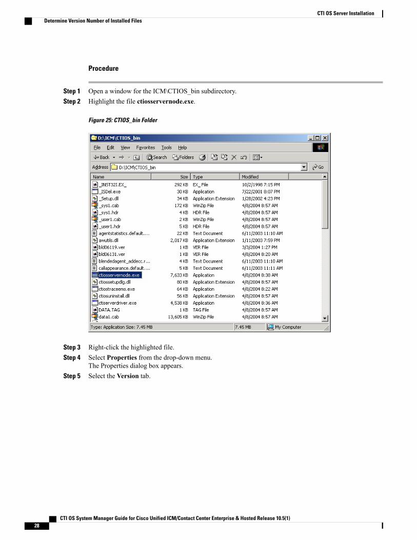
Step 1 Open a window for the ICM\CTIOS_bin subdirectory.Step 2 Highlight the file ctiosservernode.exe.
Figure 25: CTIOS_bin Folder
Step 3 Right-click the highlighted file.Step 4 Select Properties from the drop-down menu.
The Properties dialog box appears.Step 5 Select the Version tab.
CTI OS System Manager Guide for Cisco Unified ICM/Contact Center Enterprise & Hosted Release 10.5(1)28
CTI OS Server InstallationDetermine Version Number of Installed Files
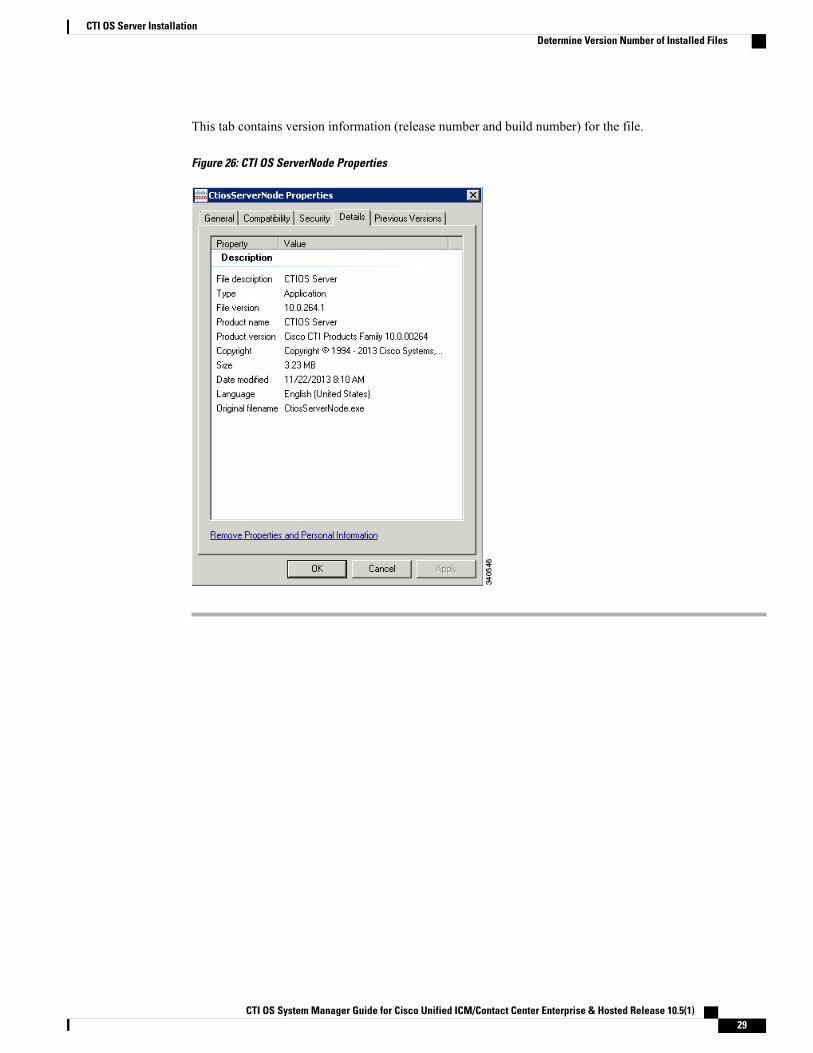
This tab contains version information (release number and build number) for the file.
Figure 26: CTI OS ServerNode Properties
CTI OS System Manager Guide for Cisco Unified ICM/Contact Center Enterprise & Hosted Release 10.5(1) 29
CTI OS Server InstallationDetermine Version Number of Installed Files

CTI OS System Manager Guide for Cisco Unified ICM/Contact Center Enterprise & Hosted Release 10.5(1)30
CTI OS Server InstallationDetermine Version Number of Installed Files
C H A P T E R 3CTI Toolkit Desktop Client Installation
This chapter provides procedures for installing the following CTI Toolkit Desktop Client components:
• CTI Toolkit Desktop applications:
◦Agent desktop (including silent monitor)
◦UCCE Supervisor Desktop (including silent monitor)
◦Tools
• Documentation
• CTI Toolkit SDK (previously the CTI OS Developer's Toolkit, including necessary files, controls,documentation, and samples needed to write custom applications):
◦Win32
◦Java
◦.NET
It also provides procedures for enabling the Emergency Call and Supervisory Call buttons, which enable anagent to make a call to a supervisor.
Before you begin installation, verify that your system meets the hardware and software requirements forthe components that you plan to install. See Compatibility Matrix for Unified CCE. For details on usingUnified CCE in a virtualized environment, see Virtualization for Unified CCE.
Note
• Upgrade from Previous Version, page 32
• Install Cisco CTI Toolkit Desktop Client Component, page 32
• Uninstall CTI Toolkit, page 39
• Determine Version Number of Installed CTI Toolkit Files, page 39
• Unified CM Intercept Configuration Requirement, page 41
• Configure Supervisory Assistance Features, page 41
CTI OS System Manager Guide for Cisco Unified ICM/Contact Center Enterprise & Hosted Release 10.5(1) 31
• Video Configuration, page 45
Upgrade from Previous VersionIf you are upgrading from a previous CTI OS release, you need not uninstall the CTI Toolkit Desktop Clientsoftware before you install the next CTI Toolkit Desktop Client release.
Install Cisco CTI Toolkit Desktop Client ComponentTo install the CTI Toolkit Desktop Client components, perform the following steps.
Procedure
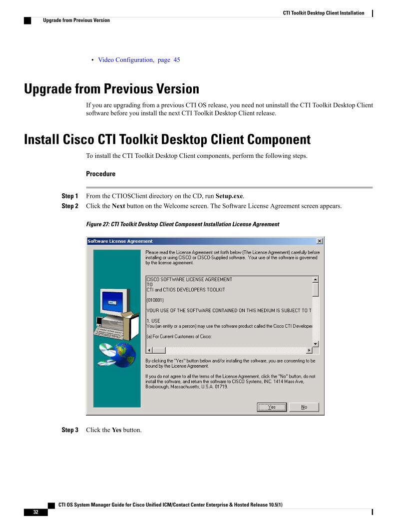
Step 1 From the CTIOSClient directory on the CD, run Setup.exe.Step 2 Click the Next button on the Welcome screen. The Software License Agreement screen appears.
Figure 27: CTI Toolkit Desktop Client Component Installation License Agreement
Step 3 Click the Yes button.
CTI OS System Manager Guide for Cisco Unified ICM/Contact Center Enterprise & Hosted Release 10.5(1)32
CTI Toolkit Desktop Client InstallationUpgrade from Previous Version
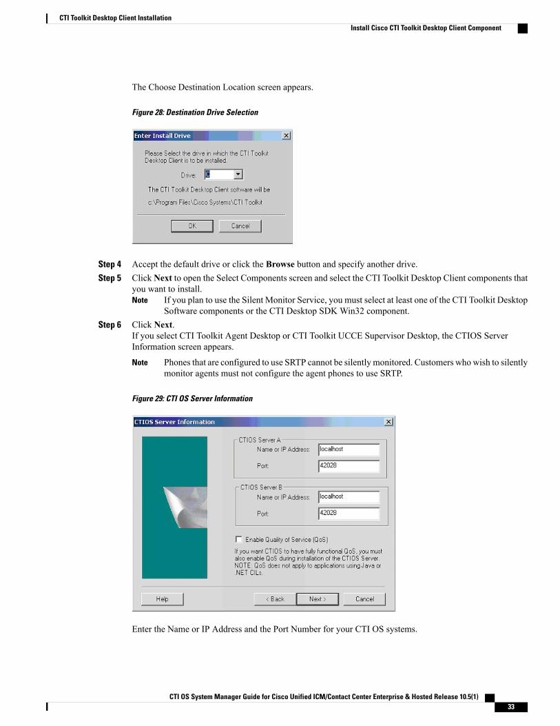
The Choose Destination Location screen appears.
Figure 28: Destination Drive Selection
Step 4 Accept the default drive or click the Browse button and specify another drive.Step 5 Click Next to open the Select Components screen and select the CTI Toolkit Desktop Client components that
you want to install.If you plan to use the Silent Monitor Service, you must select at least one of the CTI Toolkit DesktopSoftware components or the CTI Desktop SDK Win32 component.
Note
Step 6 Click Next.If you select CTI Toolkit Agent Desktop or CTI Toolkit UCCE Supervisor Desktop, the CTIOS ServerInformation screen appears.
Phones that are configured to use SRTP cannot be silently monitored. Customers who wish to silentlymonitor agents must not configure the agent phones to use SRTP.
Note
Figure 29: CTI OS Server Information
Enter the Name or IP Address and the Port Number for your CTI OS systems.
CTI OS System Manager Guide for Cisco Unified ICM/Contact Center Enterprise & Hosted Release 10.5(1) 33
CTI Toolkit Desktop Client InstallationInstall Cisco CTI Toolkit Desktop Client Component
If you enable the QoS checkbox during the CTI OS Server Installation, you must select the checkboxat this stage.
Note
Step 7 Click the Next button.The Start Copying Files screen appears.
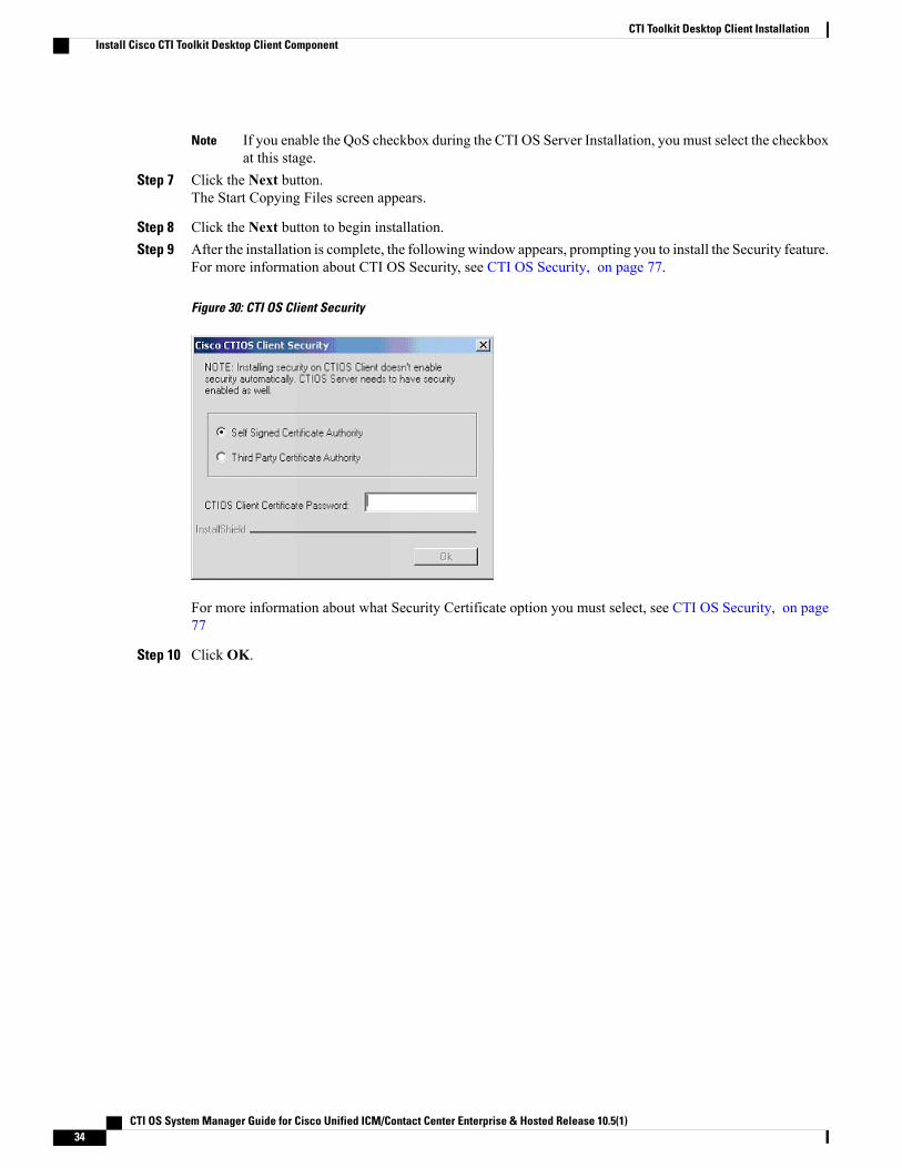
Step 8 Click the Next button to begin installation.Step 9 After the installation is complete, the following window appears, prompting you to install the Security feature.
For more information about CTI OS Security, see CTI OS Security, on page 77.
Figure 30: CTI OS Client Security
For more information about what Security Certificate option you must select, see CTI OS Security, on page77
Step 10 Click OK.
CTI OS System Manager Guide for Cisco Unified ICM/Contact Center Enterprise & Hosted Release 10.5(1)34
CTI Toolkit Desktop Client InstallationInstall Cisco CTI Toolkit Desktop Client Component
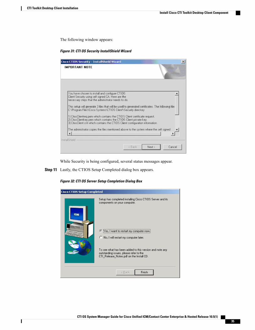
The following window appears:
Figure 31: CTI OS Security InstallShield Wizard
While Security is being configured, several status messages appear.
Step 11 Lastly, the CTIOS Setup Completed dialog box appears.
Figure 32: CTI OS Server Setup Completion Dialog Box
CTI OS System Manager Guide for Cisco Unified ICM/Contact Center Enterprise & Hosted Release 10.5(1) 35
CTI Toolkit Desktop Client InstallationInstall Cisco CTI Toolkit Desktop Client Component
Step 12 Specify whether or not you want to restart your computer. Click the Finish button to exit Setup.
LocalizationNext, import the configLanguages.reg registry, which is the registry file to configure language libraries forthe CTI OSAgent and Supervisor phones. The following example provides steps for setting the CTIOS desktoplanguage to French Canadian.
1 Log out of the CTIOS desktop.
2 Open the Registry Editor.
3 Import the ConfigLanguages.reg from the location C:\Program Files (x86)\CiscoSystems\CTIOS Client\CTIOS Toolkit\Win32 CIL\InternationalizationKit\Languages.
4 Refresh the Registry Editor and navigate to HKEY_CURRENT_USER\Software\Cisco Systems,Inc.\CTI Desktop\Shared\Languages\<LAN> where <LAN> is the abbreviation for thelanguage code. In this example it will be FRC, as this customer is setting a French Canadian Localization.
5 Set the value of the DLL Key using the following path: C:\Program Files (x86)\CiscoSystems\CTIOS Client\CTIOS Toolkit\Win32 CIL\InternationalizationKit\Languages\ctioslanguage.FRC.dll.
6 Set the value of the Language Code key to c0c (Hexadecimal).
7 Navigate to the HKEY_CURRENT_USER\Software\Cisco Systems, Inc.\CTIDesktop\Shared\Languages\Last Language and set the value of Language Code to c0c(Hexadecimal).
If the value Last Language key is not set, the CTIOS uses the default locale of the Windows operatingsystem.
Note
8 Re-launch the CTIOS client desktop.
Installed FilesWhen you install the CTI Toolkit Agent Desktop or the CTI Toolkit UCCE Supervisor Desktop, the CTIToolkit installation process installs a number of dynamic link libraries (DLLs). The installation processregisters many of these DLLs automatically, but you must manually register some of these DLLs to workcorrectly.
The following table lists the Windows DLLs that are installed with the CTI Toolkit Agent Desktop or the CTIToolkit UCCE Supervisor Desktop, along with the command line entry for manually registering the DLL (ifneeded).
CTI OS System Manager Guide for Cisco Unified ICM/Contact Center Enterprise & Hosted Release 10.5(1)36
CTI Toolkit Desktop Client InstallationLocalization
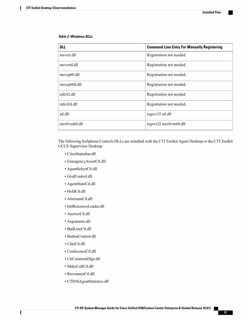
Table 2: Windows DLLs
Command Line Entry For Manually RegisteringDLL
Registration not needed.msvcrt.dll
Registration not needed.msvcrtd.dll
Registration not needed.msvcp60.dll
Registration not needed.msvcp60d.dll
Registration not needed.mfc42.dll
Registration not needed.mfc42d.dll
regsvr32 atl.dllatl.dll
regsvr32 msvbvm60.dllmsvbvm60.dll
The following Softphone Controls DLLs are installed with the CTI Toolkit Agent Desktop or the CTI ToolkitUCCE Supervisor Desktop:
• CtiosStatusbar.dll
• EmergencyAssistCtl.dll
• AgentSelectCtl.dll
• GridControl.dll
• AgentStateCtl.dll
• HoldCtl.dll
• AlternateCtl.dll
• IntlResourceLoader.dll
• AnswerCtl.dll
• Arguments.dll
• BadLineCtl.dll
• ButtonControl.dll
• ChatCtl.dll
• ConferenceCtl.dll
• CtiCommonDlgs.dll
• MakeCallCtl.dll
• ReconnectCtl.dll
• CTIOSAgentStatistics.dll
CTI OS System Manager Guide for Cisco Unified ICM/Contact Center Enterprise & Hosted Release 10.5(1) 37
CTI Toolkit Desktop Client InstallationInstalled Files
• RecordCtl.dll
• CTIOSCallAppearance.dll
• SubclassForm.dll
• CTIOSClient.dll
• SupervisorOnlyCtl.dll
• CTIOSSessionResolver.dll
• TransferCtl.dll
• CTIOSSkillGroupStatistics.dll
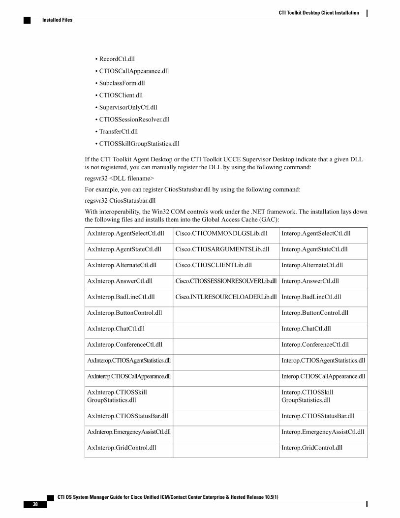
If the CTI Toolkit Agent Desktop or the CTI Toolkit UCCE Supervisor Desktop indicate that a given DLLis not registered, you can manually register the DLL by using the following command:
regsvr32 <DLL filename>
For example, you can register CtiosStatusbar.dll by using the following command:
regsvr32 CtiosStatusbar.dll
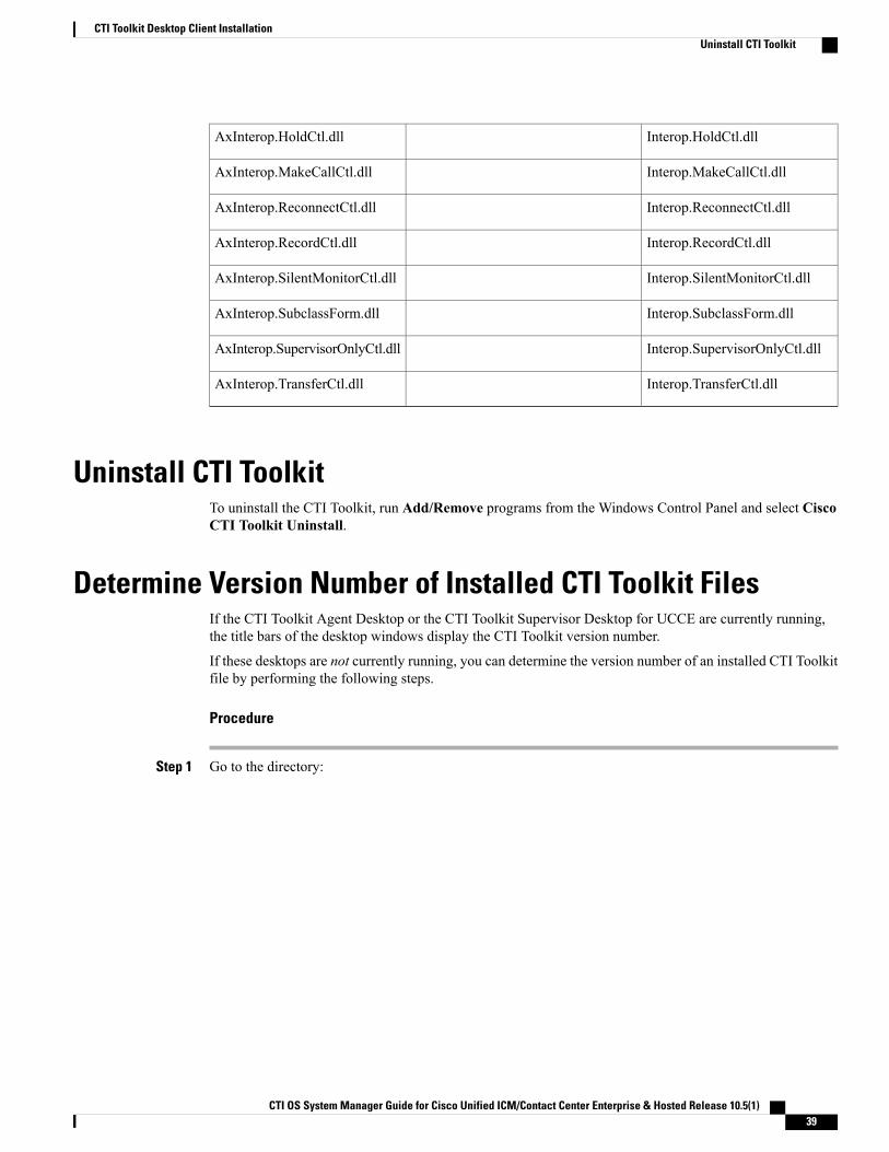
With interoperability, the Win32 COM controls work under the .NET framework. The installation lays downthe following files and installs them into the Global Access Cache (GAC):
Interop.AgentSelectCtl.dllCisco.CTICOMMONDLGSLib.dllAxInterop.AgentSelectCtl.dll
Interop.AgentStateCtl.dllCisco.CTIOSARGUMENTSLib.dllAxInterop.AgentStateCtl.dll
Interop.AlternateCtl.dllCisco.CTIOSCLIENTLib.dllAxInterop.AlternateCtl.dll
Interop.AnswerCtl.dllCisco.CTIOSSESSIONRESOLVERLib.dllAxInterop.AnswerCtl.dll
Interop.BadLineCtl.dllCisco.INTLRESOURCELOADERLib.dllAxInterop.BadLineCtl.dll
Interop.ButtonControl.dllAxInterop.ButtonControl.dll
Interop.ChatCtl.dllAxInterop.ChatCtl.dll
Interop.ConferenceCtl.dllAxInterop.ConferenceCtl.dll
Interop.CTIOSAgentStatistics.dllAxInterop.CTIOSAgentStatistics.dll
Interop.CTIOSCallAppearance.dllAxInterop.CTIOSCallAppearance.dll
Interop.CTIOSSkillGroupStatistics.dll
AxInterop.CTIOSSkillGroupStatistics.dll
Interop.CTIOSStatusBar.dllAxInterop.CTIOSStatusBar.dll
Interop.EmergencyAssistCtl.dllAxInterop.EmergencyAssistCtl.dll
Interop.GridControl.dllAxInterop.GridControl.dll
CTI OS System Manager Guide for Cisco Unified ICM/Contact Center Enterprise & Hosted Release 10.5(1)38
CTI Toolkit Desktop Client InstallationInstalled Files
Interop.HoldCtl.dllAxInterop.HoldCtl.dll
Interop.MakeCallCtl.dllAxInterop.MakeCallCtl.dll
Interop.ReconnectCtl.dllAxInterop.ReconnectCtl.dll
Interop.RecordCtl.dllAxInterop.RecordCtl.dll
Interop.SilentMonitorCtl.dllAxInterop.SilentMonitorCtl.dll
Interop.SubclassForm.dllAxInterop.SubclassForm.dll
Interop.SupervisorOnlyCtl.dllAxInterop.SupervisorOnlyCtl.dll
Interop.TransferCtl.dllAxInterop.TransferCtl.dll
Uninstall CTI ToolkitTo uninstall the CTI Toolkit, run Add/Remove programs from the Windows Control Panel and select CiscoCTI Toolkit Uninstall.
Determine Version Number of Installed CTI Toolkit FilesIf the CTI Toolkit Agent Desktop or the CTI Toolkit Supervisor Desktop for UCCE are currently running,the title bars of the desktop windows display the CTI Toolkit version number.
If these desktops are not currently running, you can determine the version number of an installed CTI Toolkitfile by performing the following steps.
Procedure
Step 1 Go to the directory:
CTI OS System Manager Guide for Cisco Unified ICM/Contact Center Enterprise & Hosted Release 10.5(1) 39
CTI Toolkit Desktop Client InstallationUninstall CTI Toolkit
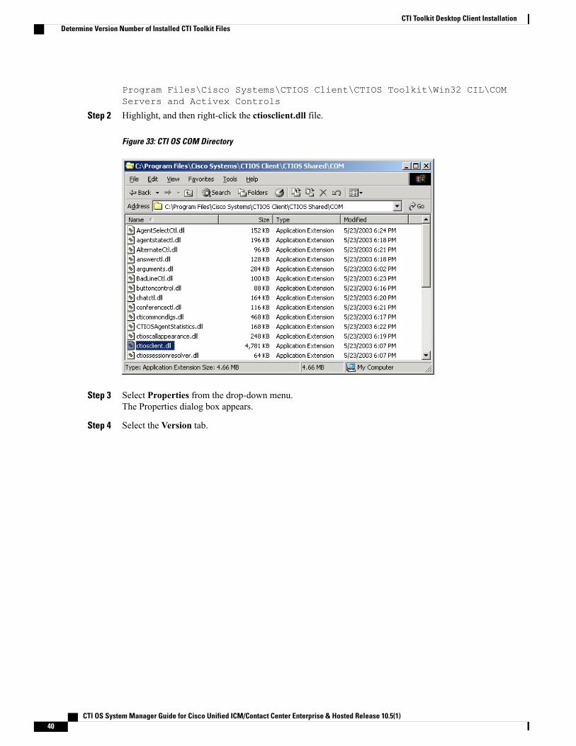
Program Files\Cisco Systems\CTIOS Client\CTIOS Toolkit\Win32 CIL\COMServers and Activex Controls
Step 2 Highlight, and then right-click the ctiosclient.dll file.
Figure 33: CTI OS COM Directory
Step 3 Select Properties from the drop-down menu.The Properties dialog box appears.
Step 4 Select the Version tab.
CTI OS System Manager Guide for Cisco Unified ICM/Contact Center Enterprise & Hosted Release 10.5(1)40
CTI Toolkit Desktop Client InstallationDetermine Version Number of Installed CTI Toolkit Files
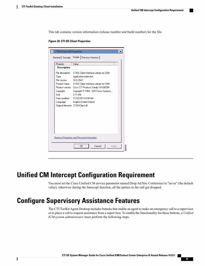
This tab contains version information (release number and build number) for the file.
Figure 34: CTI OS Client Properties
Unified CM Intercept Configuration RequirementYou must set the Cisco Unified CM service parameter named Drop Ad Hoc Conference to “never” (the defaultvalue), otherwise during the Intercept function, all the parties in the call get dropped.
Configure Supervisory Assistance FeaturesThe CTI Toolkit Agent Desktop includes buttons that enable an agent to make an emergency call to a supervisoror to place a call to request assistance from a supervisor. To enable the functionality for these buttons, aUnifiedICM system administrator must perform the following steps.
CTI OS System Manager Guide for Cisco Unified ICM/Contact Center Enterprise & Hosted Release 10.5(1) 41
CTI Toolkit Desktop Client InstallationUnified CM Intercept Configuration Requirement
Procedure
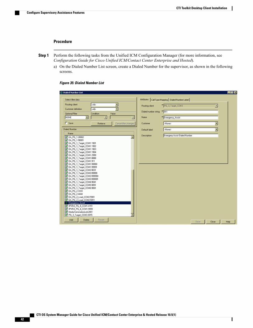
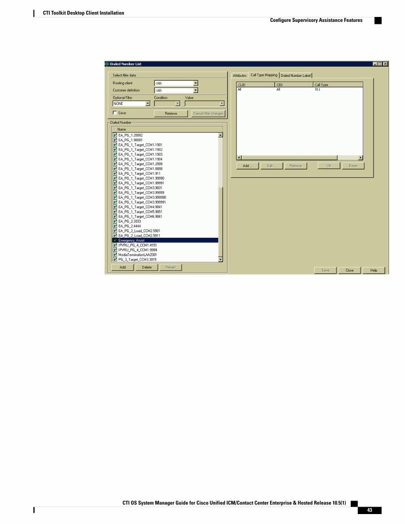
Step 1 Perform the following tasks from the Unified ICM Configuration Manager (for more information, seeConfiguration Guide for Cisco Unified ICM/Contact Center Enterprise and Hosted).a) On the Dialed Number List screen, create a Dialed Number for the supervisor, as shown in the following
screens.
Figure 35: Dialed Number List
CTI OS System Manager Guide for Cisco Unified ICM/Contact Center Enterprise & Hosted Release 10.5(1)42
CTI Toolkit Desktop Client InstallationConfigure Supervisory Assistance Features
CTI OS System Manager Guide for Cisco Unified ICM/Contact Center Enterprise & Hosted Release 10.5(1) 43
CTI Toolkit Desktop Client InstallationConfigure Supervisory Assistance Features
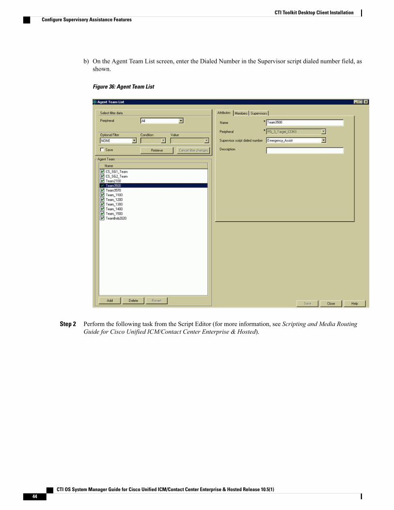
b) On the Agent Team List screen, enter the Dialed Number in the Supervisor script dialed number field, asshown.
Figure 36: Agent Team List
Step 2 Perform the following task from the Script Editor (for more information, see Scripting and Media RoutingGuide for Cisco Unified ICM/Contact Center Enterprise & Hosted).
CTI OS System Manager Guide for Cisco Unified ICM/Contact Center Enterprise & Hosted Release 10.5(1)44
CTI Toolkit Desktop Client InstallationConfigure Supervisory Assistance Features
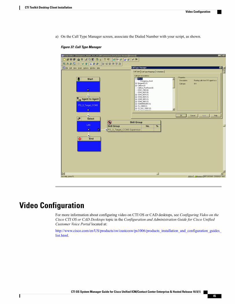
a) On the Call Type Manager screen, associate the Dialed Number with your script, as shown.
Figure 37: Call Type Manager
Video ConfigurationFor more information about configuring video on CTI OS or CAD desktops, see Configuring Video on theCisco CTI OS or CAD Desktops topic in the Configuration and Administration Guide for Cisco UnifiedCustomer Voice Portal located at:
http://www.cisco.com/en/US/products/sw/custcosw/ps1006/products_installation_and_configuration_guides_list.html.
CTI OS System Manager Guide for Cisco Unified ICM/Contact Center Enterprise & Hosted Release 10.5(1) 45
CTI Toolkit Desktop Client InstallationVideo Configuration

CTI OS System Manager Guide for Cisco Unified ICM/Contact Center Enterprise & Hosted Release 10.5(1)46
CTI Toolkit Desktop Client InstallationVideo Configuration
C H A P T E R 4CTI OS Silent Monitor Installation andConfiguration
You must install the CTI OS before installing and configuring the silent monitor service.Note
• Silent Monitor Service Installation and Configuration, page 47
Silent Monitor Service Installation and ConfigurationThis section provides an overview of the silent monitor service and discusses the tasks involved in installingand configuring the silent monitor service.
Note • The terms silent monitor service and silent monitor server are used throughout this document. Silentmonitor service refers to a silent monitoring service running on agent or supervisor's desktop computeror Citrix client. This service handles silent monitoring functionality for one agent or supervisor.Silent monitor server refers to a silent monitor service providing silent monitoring functionality fora group of mobile agents. These agents share the same gateway
Silent Monitor Service OverviewThe silent monitor functionality resides in a separate silent monitor service, rather than in the CIL. This isnecessary to support both Citrix and mobile agent environments. C++ agent and supervisor desktopscommunicate with the silent monitor service via TCP connection. The agent desktop uses the silent monitorservice to forward a voice stream to the supervisor's silent monitor service that plays the stream on thesupervisor's computer speakers.
In a traditional UCCE environment, the silent monitor service runs alongside the agent and supervisor desktopson the agent's and supervisor's computer. However, mobile agent and Citrix environments do not give theCIL access to the voice packets because the agent's computer is not connected to the network through the
CTI OS System Manager Guide for Cisco Unified ICM/Contact Center Enterprise & Hosted Release 10.5(1) 47
agent's phone. In a Citrix environment, the desktop is actually running on the Citrix Presentation Server. Theagents and supervisor computers are running Citrix clients. These clients render the user interface for thedesktops, but the actual desktop processes are running on the presentation server. In a Citrix deployment, thesilent monitor service is deployed on the Citrix client where it has access to the agent's voice stream or thesupervisor's speaker. In a Citrix deployment, a silent monitor service is deployed on the agent's Citrix clientwhere it has access to the voice stream. The agent desktop uses this service to forward the agent's voice streamto the supervisor. The supervisor's Citrix client also runs a silent monitor service. This service plays backstreams from monitored agents using the speaker on the Citrix client.
In mobile agent deployments, the voice path crosses the Public Switched Telephone Network (PSTN) andtwo gateways. One gateway control calls from customer phones. The other gateway controls agent calls. Inthis deployment, the silent monitor service is deployed from a SPAN port on the same switch as the agentgateway. This provides the silent monitor service with access to voice streams passing through the gateway.In a mobile agent environment, the supervisor still uses a silent monitor service on the supervisor's desktopor Citrix client to play back the voice stream.
CTI OS ConnectionsTo support remote silent monitoring, there can be up to nine All Event connections, including both CTI serverand CTIOS server connections, subject to the following rules:
• Two CTI server All Event connections must be dedicated to CTIOS server
• Seven connections are available for other CTI server and CTIOS server All Events connections
• Of these seven connections, a maximum of five can be of the same connection type (5 CTI serverconnections or 5 CTIOS server connections)
• Average skills per agent should not exceed 10
How desktops Connect to Silent Monitor ServicesThe following is the supervisor desktop connection algorithm:
1 If the supervisor desktop is running under Citrix, determine the IP address of the Citrix client. Connect tothe silent monitor service running at port 42228 on the Citrix client.
2 If the supervisor desktop is not running under Citrix, connect to the silent monitor service running at port42228 on localhost.
While CTI OS silent monitor clusters use port 42228 (the default), the silent monitor peers utilize port42029 for communications purposes.
Note
The following is the agent desktop connection algorithm:
1 If the agent desktop's connection profile specifies a silent monitor server or set of silent monitor servers,randomly choose a silent monitor server to connect to using the port present in the connection profile. Formore information about how you configure a connection profile to include silent monitor services, seeCTI OS Server Installation, on page 13.
CTI OS System Manager Guide for Cisco Unified ICM/Contact Center Enterprise & Hosted Release 10.5(1)48
CTI OS Silent Monitor Installation and ConfigurationCTI OS Connections
2 If the agent desktop is running under Citrix, determine the IP address of the Citrix client. Connect to thesilent monitor service running at port 42228 on the Citrix client.
3 If the agent desktop is not running under Citrix, connect to the silent monitor service running at port 42228on localhost.
You can use a connection profile to override port 42228. In this case, desktops use the preceding algorithmsto determine the address of the silent monitor service. After the address is determined, desktops connectusing the determined address and the port that is present in the connection profile.
Note
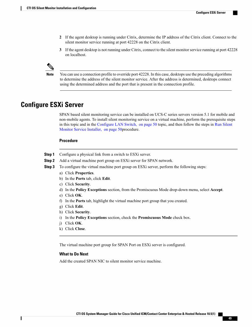
Configure ESXi ServerSPAN based silent monitoring service can be installed on UCS-C series servers version 5.1 for mobile andnon-mobile agents. To install silent monitoring service on a virtual machine, perform the prerequisite stepsin this topic and in the Configure LAN Switch, on page 50 topic, and then follow the steps in Run SilentMonitor Service Installer, on page 50procedure.
Procedure
Step 1 Configure a physical link from a switch to ESXi server.Step 2 Add a virtual machine port group on ESXi server for SPAN network.Step 3 To configure the virtual machine port group on ESXi server, perform the following steps:
a) Click Properties.b) In the Ports tab, click Edit.c) Click Security.d) In the Policy Exceptions section, from the Promiscuous Mode drop-down menu, select Accept.e) Click OK.f) In the Ports tab, highlight the virtual machine port group that you created.g) Click Edit.h) Click Security.i) In the Policy Exceptions section, check the Promiscuous Mode check box.j) Click OK.k) Click Close.
The virtual machine port group for SPAN Port on ESXi server is configured.
What to Do Next
Add the created SPAN NIC to silent monitor service machine.
CTI OS System Manager Guide for Cisco Unified ICM/Contact Center Enterprise & Hosted Release 10.5(1) 49
CTI OS Silent Monitor Installation and ConfigurationConfigure ESXi Server
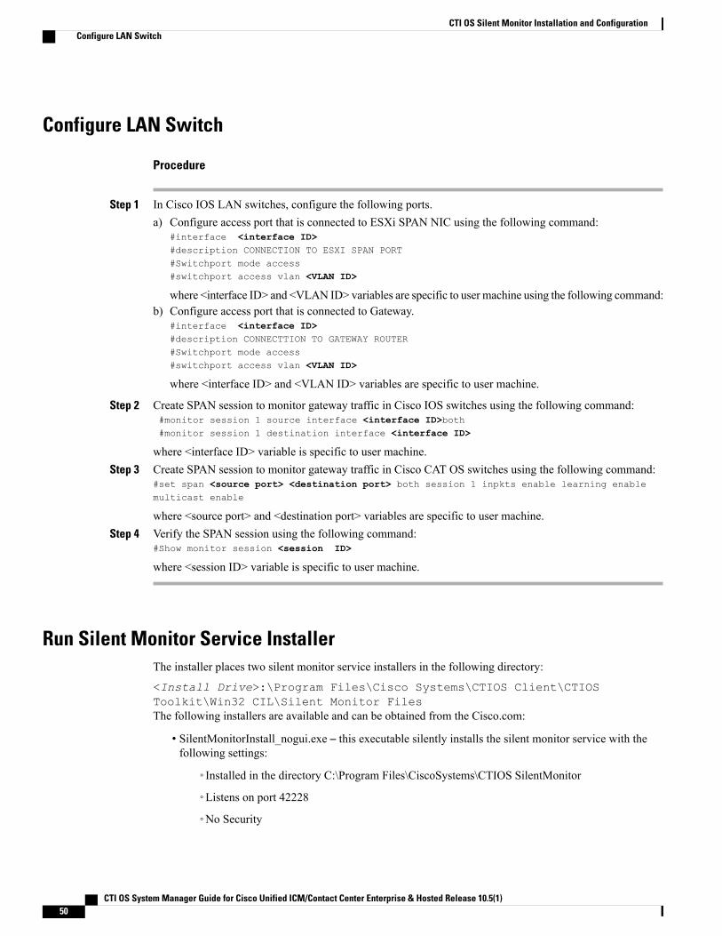
Configure LAN Switch
Procedure
Step 1 In Cisco IOS LAN switches, configure the following ports.a) Configure access port that is connected to ESXi SPAN NIC using the following command:
#interface <interface ID>#description CONNECTION TO ESXI SPAN PORT#Switchport mode access#switchport access vlan <VLAN ID>
where <interface ID> and <VLAN ID> variables are specific to user machine using the following command:b) Configure access port that is connected to Gateway.
#interface <interface ID>#description CONNECTTION TO GATEWAY ROUTER#Switchport mode access#switchport access vlan <VLAN ID>
where <interface ID> and <VLAN ID> variables are specific to user machine.
Step 2 Create SPAN session to monitor gateway traffic in Cisco IOS switches using the following command:#monitor session 1 source interface <interface ID>both#monitor session 1 destination interface <interface ID>
where <interface ID> variable is specific to user machine.Step 3 Create SPAN session to monitor gateway traffic in Cisco CAT OS switches using the following command:
#set span <source port> <destination port> both session 1 inpkts enable learning enablemulticast enable
where <source port> and <destination port> variables are specific to user machine.Step 4 Verify the SPAN session using the following command:
#Show monitor session <session ID>
where <session ID> variable is specific to user machine.
Run Silent Monitor Service InstallerThe installer places two silent monitor service installers in the following directory:
<Install Drive>:\Program Files\Cisco Systems\CTIOS Client\CTIOSToolkit\Win32 CIL\Silent Monitor FilesThe following installers are available and can be obtained from the Cisco.com:
• SilentMonitorInstall_nogui.exe – this executable silently installs the silent monitor service with thefollowing settings:
◦Installed in the directory C:\Program Files\CiscoSystems\CTIOS SilentMonitor
◦Listens on port 42228
◦No Security
CTI OS System Manager Guide for Cisco Unified ICM/Contact Center Enterprise & Hosted Release 10.5(1)50
CTI OS Silent Monitor Installation and ConfigurationConfigure LAN Switch

This executable runs automatically when you update from one release to another. It replaces the earlierrelease CIL with the newer CIL and installs and starts the silent monitor service so that the agent andsupervisor desktops do not lose functionality. Running this executable is sufficient only if you do notwish to override the default settings or enable Security.
This executable only works on the machines that either do not have WinPCap installedor have WinPCap Release 3.0 installed.
Note
• SMSelfExtractedInstallPackage.exe – this executable extracts the silent monitor service setup programinto the following directory:
<Install Drive>:\Program Files\Cisco Systems\CTIOS Client\CTIOSToolkit\Win32 CIL\Silent Monitor Files\SilentMonitorServiceInstall
Run this executable if you wish to specify a different destination directory or port, or if you want toenable Security.
Procedure
Step 1 To run this executable silently:a) Open a command prompt window and navigate to the directory <Install Drive>:\Program
Files\Cisco Systems\CTIOS Client\CTIOS Toolkit\Win32 CIL\Silent MonitorFiles\SilentMonitorServiceInstall.
b) Enter the command setup.exe /s .This runs the executable with the default values specified in the supplied answer file setup.iss.To override the default values, edit this answer file and change the values that you wish to change.
Note
Step 2 To run the full installation program for this executable, perform the following steps:a) In Windows Explorer, navigate to the directory <Install Drive>:\Program Files\Cisco
Systems\CTIOS Client\CTIOS Toolkit\Win32 CIL\Silent MonitorFiles\SilentMonitorServiceInstall.
CTI OS System Manager Guide for Cisco Unified ICM/Contact Center Enterprise & Hosted Release 10.5(1) 51
CTI OS Silent Monitor Installation and ConfigurationRun Silent Monitor Service Installer
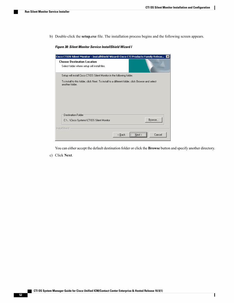
b) Double-click the setup.exe file. The installation process begins and the following screen appears.
Figure 38: Silent Monitor Service InstallShield Wizard I
You can either accept the default destination folder or click theBrowse button and specify another directory.
c) Click Next.
CTI OS System Manager Guide for Cisco Unified ICM/Contact Center Enterprise & Hosted Release 10.5(1)52
CTI OS Silent Monitor Installation and ConfigurationRun Silent Monitor Service Installer
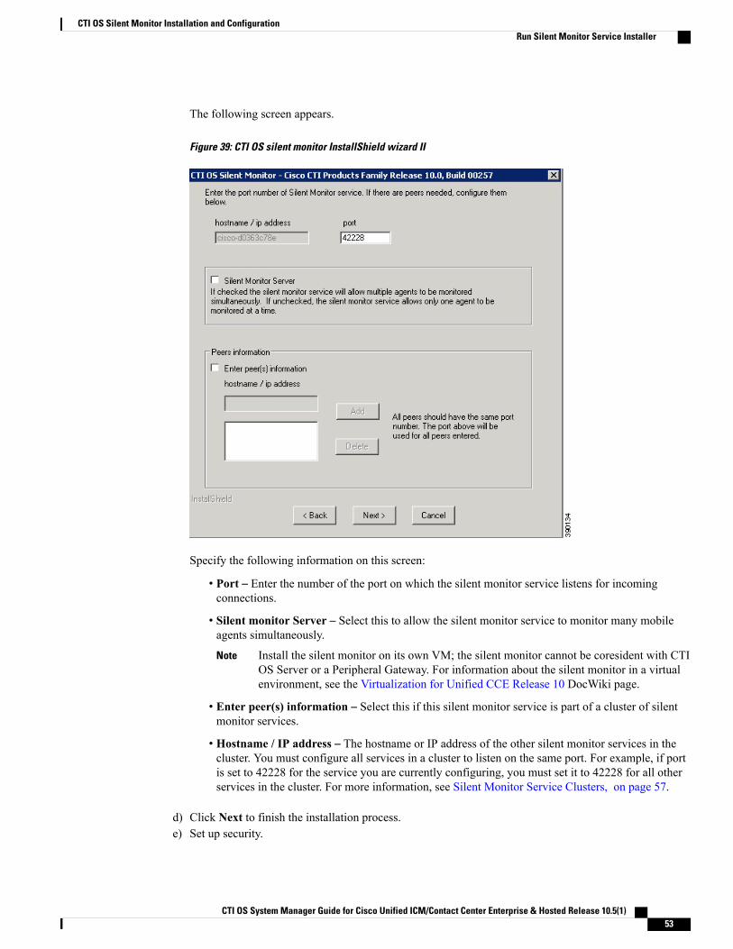
The following screen appears.
Figure 39: CTI OS silent monitor InstallShield wizard II
Specify the following information on this screen:
• Port – Enter the number of the port on which the silent monitor service listens for incomingconnections.
• Silent monitor Server – Select this to allow the silent monitor service to monitor many mobileagents simultaneously.
Install the silent monitor on its own VM; the silent monitor cannot be coresident with CTIOS Server or a Peripheral Gateway. For information about the silent monitor in a virtualenvironment, see the Virtualization for Unified CCE Release 10 DocWiki page.
Note
• Enter peer(s) information – Select this if this silent monitor service is part of a cluster of silentmonitor services.
• Hostname / IP address – The hostname or IP address of the other silent monitor services in thecluster. You must configure all services in a cluster to listen on the same port. For example, if portis set to 42228 for the service you are currently configuring, you must set it to 42228 for all otherservices in the cluster. For more information, see Silent Monitor Service Clusters, on page 57.
d) Click Next to finish the installation process.e) Set up security.
CTI OS System Manager Guide for Cisco Unified ICM/Contact Center Enterprise & Hosted Release 10.5(1) 53
CTI OS Silent Monitor Installation and ConfigurationRun Silent Monitor Service Installer
Depending on whether you want to use a self-signed certificate authority (CA) or a third-party CA, followthe instructions in Sign a Silent Monitor Server Certificate Request with Self-Signed CA, on page 54 orSign a Silent Monitor Service Certificate Request with Third-Party CA, on page 55.
Related Topics
CTI OS Security, on page 77
Sign a Silent Monitor Server Certificate Request with Self-Signed CA
Procedure
Step 1 If the self-signed CA does not exist, then run CreateSelfSignedCASetupPackage.exe and store all the filesthat were created by the CreateSelfSignedCASetupPackage.exe program in a safe place. This step generatesCtiosRoot.pem and CtiosRootCert.pem in the same folder from where the setup is run.
Step 2 You must copy both CtiosServerKey.pem and CtiosServerReq.pem files from the CTI OS server machinelocated indrive:\icm\Instance name\CTIOS1\Security to the same directory as CtiosRoot.pemand CtiosRootCert.pem.
Step 3 Run SignCertificateSetupPackage.exe from the same directory where CtiosServerKey.pem,CtiosServerReq.pem, CtiosRoot.pem, and CtiosRootCert.pem reside, select CTI OS Server Certificate Request,and enter the Ctios Certificate Authority password. This step generates CtiosServer.pem file if it is successful;otherwise it displays an error message.
Step 4 Copy CtiosServer.pem and CtiosRootCert.pem back to the machine where silent monitor server resides andsave them in the C:\Cisco Systems\CTIOS\Silent Monitor\Security directory.
Step 5 Delete CtiosServerkey.pem located in drive:\icm\Instance name\CTIOS1\Security from themachine where CTI OS Server is installed.
Step 6 Delete CtiosServerKey.pem, CtiosServerReq.pem, and CtiosServer.pem from the machine whereSignCertificateSetupPackage.exe ran.
Step 7 If the silent monitor server machine has a peer server, then:a) Copy CtiosClientkey.pem and CtiosClientreq.pem files from the silent monitor server machine to the
machine where CtiosRoot.pem and CtiosRootCert.pem reside. You must copy both CtiosClientkey.pemand CtiosClientreq.pem files to the same directory as CtiosRoot.pem and CtiosRootCert.pem.
b) Run SignCertificateSetupPackage.exe from the same directory where CtiosClientkey.pem,CtiosClientreq.pem, CtiosRoot.pem, and CtiosRootCert.pem reside, select CTI Toolkit Desktop ClientCertificateRequest, and enter the Ctios CertificateAuthority password. This step generates CtiosClient.pemfile if it is successful, otherwise it displays an error message.
c) Copy CtiosClient.pem to the machine where silent monitor server resides and save it in the C:\CiscoSystems\CTIOS\Silent Monitor\Security directory.
d) Delete CtiosClientkey.pem from the machine where silent monitor server is installed.e) Delete CtiosClientkey.pem, CtiosClientreq.pem, and CtiosClient.pem from the machine where
SignCertificateSetupPackage.exe ran.
CTI OS System Manager Guide for Cisco Unified ICM/Contact Center Enterprise & Hosted Release 10.5(1)54
CTI OS Silent Monitor Installation and ConfigurationRun Silent Monitor Service Installer
Sign a Silent Monitor Service Certificate Request with Third-Party CAFollow these steps to sign a silent monitor service certificate request.
Procedure
Step 1 Copy CtiosServerReq.pem file from the silent monitor service machine to the machine where the third-partyCA resides.
Step 2 Signing silent monitor service certificate request (CtiosServerReq.pem) with third-party CA generates a silentmonitor service certificate. Rename it CtiosServerCert.pem.
Step 3 The third-party CA has its certificate public information in a file. Rename this file CtiosRootCert.pem.Step 4 Copy CtiosServerCert.pem and CtiosRootCert.pem to the machine where the silent monitor service resides
and save them in the C:\Cisco Systems\CTIOS\Silent Monitor\Security directory.Step 5 On the silent monitor servicemachine, copy the data in CtiosServerCert.pem and the data in CtiosServerkey.pem
files into one file called CtiosServer.pem. The order is very important, so CtiosServer.pem must containCtiosServerCert.pem data first and CtiosServerkey.pem data second.
Step 6 Delete CtiosServerCert.pem and CtiosServerkey.pem from the silent monitor service machine.Step 7 If the silent monitor service machine has a peer server, then:
a) Copy CtiosClientreq.pem file from the silent monitor service machine to the machine where the third-partyCA resides.
b) Signing CTI Toolkit Desktop Client certificate request (CtiosClientreq.pem) with third-party CA generatesa CTI Toolkit Desktop Client certificate. Rename it CtiosClientCert.pem.
c) Copy CtiosClientCert.pem file to the machine where the silent monitor service resides and save it in theC:\Cisco Systems\CTIOS\Silent Monitor\Security directory.
d) On the silent monitor service machine, copy the data in CtiosClientCert.pem and the data in theCtiosClientkey.pem files into one file called CtiosClient.pem. The order is very important, soCtiosClient.pem must contain CtiosClientCert.pem data first and CtiosClientkey.pem data second.
e) Delete CtiosClientCert.pem and CtiosClientkey.pem from the silent monitor service machine.If you are installing silent monitor service on a virtual machine, perform the steps listed in Configure ESXiServer, on page 49 and Configure LAN Switch, on page 50 to complete the installation process.
Additional Configuration StepsThis section discusses the silent monitor service configuration steps that you must perform after you installthe silent monitor service. These steps are necessary to deliver silent monitor service connection informationto client applications.
Rerunning CTI OS Server SetupRerun CTI OS Server setup to perform the following tasks:
• To configure agents to use the Silent Monitor service.
CTI OS System Manager Guide for Cisco Unified ICM/Contact Center Enterprise & Hosted Release 10.5(1) 55
CTI OS Silent Monitor Installation and ConfigurationAdditional Configuration Steps
• To configure security for clients, so they can connect to Silent Monitor services that have securityenabled.
• To configure mobile agents.When you rerun setup, enable mobile agent and the appropriate agent mode.This modifies the connection profile information in the registry. The ShowFieldBitMask is modifiedto display the RAS fields on the login dialog box and the RasCallMode registry key is added.
• To enable the default tracemark set it to 0x3.
Related Topics
CTI OS Server Installation, on page 13
Silent Monitor Service Installation in Citrix EnvironmentThe following considerations apply when you install and configure the silent monitor service in a Citrixenvironment:
• You can use the SilentMonitorInstall_nogui.exe executable to silently install the silent monitor serviceon both agent and supervisor Citrix clients.
• All supervisors in a Citrix environment must have the silent monitor service installed on the computerrunning the Citrix client.
• All standard UCCE agents in a Citrix environment must have the silent monitor service installed on thecomputer running the Citrix client.
• Mobile agents in a Citrix environment do not need the silent monitor service installed because they usethe silent monitor service that is forwarding traffic from the agent gateway.
Related Topics
CTI OS Server Installation, on page 13
Additional Configuration for Mobile Agent EnvironmentsThe following configuration considerations apply to environments that run mobile agent:
• Mobile agent is not supported with Siebel.
• In a mobile agent environment, the silent monitor service uses a Switched Port Analyzer (SPAN) portto receive the voice traffic that passes through the agent gateway. Most of the time, this requires thecomputer running the silent monitor service to have two NIC cards: one to handle communications withclients, and one to receive all traffic spanned from the switch.
Some switches do allow the destination port of a SPAN configuration to act as a normal networkconnection and in that case, only one NIC card is enough. See the "Network Traffic Restrictions" sectionin www.cisco.com/en/US/products/sw/custcosw/ps1001/products_tech_note09186a008010e6ba.shtml#umnic for more information on the types of catalyst switches that don'tsupport outgoing traffic on SPAN destination port.
For example, if the agent gateway is connected to port 1 and the NIC on the silent monitor server thatreceives SPAN traffic is connected on port 10, the following commands are used to configure the SPANsession:
CTI OS System Manager Guide for Cisco Unified ICM/Contact Center Enterprise & Hosted Release 10.5(1)56
CTI OS Silent Monitor Installation and ConfigurationAdditional Configuration Steps
monitor session 1 source interface fastEthernet0/1monitor session 1 destination interface fastEthernet0/10
Refer to your switch manual for details on configuring a span port. In general, traffic to and from theagent gateway's port must be forwarded to the port that is configured to receive span traffic on the silentmonitor service.
• The SPAN source port should be set as the switch port into which the agent gateway (instead of thecaller gateway) is plugged, or the silent monitor won't work in conference call scenarios.
• There must be two gateways: one gateway for agent traffic, and another for caller traffic. If one gatewayis used for agent and caller traffic, the voice traffic does not leave the gateway and cannot be silentlymonitored.
• Voice traffic that does not leave the agent gateway or does not cross the agent gateway cannot be silentmonitored. For example, agent-to-agent and consultation calls between mobile agents that share thesame gateway cannot be silently monitored. In most mobile agent deployments, the only calls that canbe reliably silent monitored are calls between agents and customers.
• All supervisors in a mobile agent environment must have the silent monitor service installed on theirdesktop or installed on the computer running the Citrix client if the supervisor is in a Citrix environment.
• Agents do not need the silent monitor service configured on their desktops. However, you must configurethe agent to use one or more silent monitor servers in the CTI OS Server setup program.
• If there are agents that can be both mobile and traditional UCCE, there must be at least two profiles forsuch agents. One profile, used when logging in as UCCE, does not contain any silent monitor serviceinformation. A second profile, used when logging in as a mobile agent, contains information used toconnect to a silent monitor server. This enables the mobile agent to use the silent monitor service ontheir desktop computer or Citrix client and provides that mobile agent with silent monitoring functionality.
Silent Monitor Service ClustersIf more than one agent gateway is present in the call center, and an agent can use either gateway to log in,silent monitor services must be clustered to support silent monitor. You must deploy a separate silent monitorserver for each gateway. You must configure a SPAN port for each silent monitor server as described in theprevious section. You must then run the silent monitor server installer to install and configure the two silentmonitor servers as peers. After you complete this, you must set up a connection profile to instruct the agentdesktops to connect to one of the peers. (For more information on the CTI OS Server installer program, seeCTI OS Server Installation, on page 13.) To set up a connection profile, check the “Enter peer(s) information”checkbox and fill in the IP address of the other silent monitor service in the “Hostname/ip address” text boxduring silent monitor service installation (for more information, see Step 3 in the section Run Silent MonitorService Installer, on page 50).
Installation of Silent Monitor Service with Windows Firewall Service EnabledYou must create a new port with the following parameters for any Windows 2008 R2 computer that hasWindows Firewall Service enabled:
• Port Type: Silent Monitor Service Port
• Port Number: 42029
CTI OS System Manager Guide for Cisco Unified ICM/Contact Center Enterprise & Hosted Release 10.5(1) 57
CTI OS Silent Monitor Installation and ConfigurationAdditional Configuration Steps

While CTI OS silent monitor clusters use port 42228 (the default), the silent monitor peers utilize port42029 for communications purposes.
Note
Harden Silent Monitor Server SecurityYou can run the ICMSecurity Hardening script only onWindows Server 2008 R2. To apply security hardeningon a Silent Monitor Server, you must perform the following manual steps.
Procedure
Step 1 Run the executable SMSelfExtractedInstallPackage.exe, which the installation process installs in thefollowing directory:<Install Drive>:\Program Files\Cisco Systems\CTIOS Client\CTIOSToolkit\Win32 CIL\Silent Monitor FilesThis executable puts a batch file named CopySecurityHardeningFiles.bat and the SecurityTemplate directoryin the current directory.
Step 2 Run CopySecurityHardeningFiles.bat.This creates the directory C:\CiscoUtils and copies the corresponding files there.
Step 3 Go to the directory C:\CiscoUtils\SecurityTemplate.Step 4 Run the command cscript ICMSecurityHardening.vbe HARDEN.
Add Silent Monitor Service to Windows Firewall ExceptionsThe following steps describe how to add the silent monitor service as an exception if Windows Firewall isenabled on Windows Server 2008 R2.
Procedure
Step 1 From the Windows Control Panel, clickWindows Firewall.Step 2 If the message “Your PC is not Protected: Turn on Windows Firewall” appears, turn on Windows Firewall.Step 3 From the Windows Firewall dialog box, click the Exceptions tab.Step 4 Select the Silent Monitor service and specify it as an exception. If you do not see the silent monitor service
on the list of programs, click the Add Program button, and then click the Browse button.The silent monitor service executable SilentMonitorService.exe is located in the bin directory below the installdirectory.
CTI OS System Manager Guide for Cisco Unified ICM/Contact Center Enterprise & Hosted Release 10.5(1)58
CTI OS Silent Monitor Installation and ConfigurationAdditional Configuration Steps
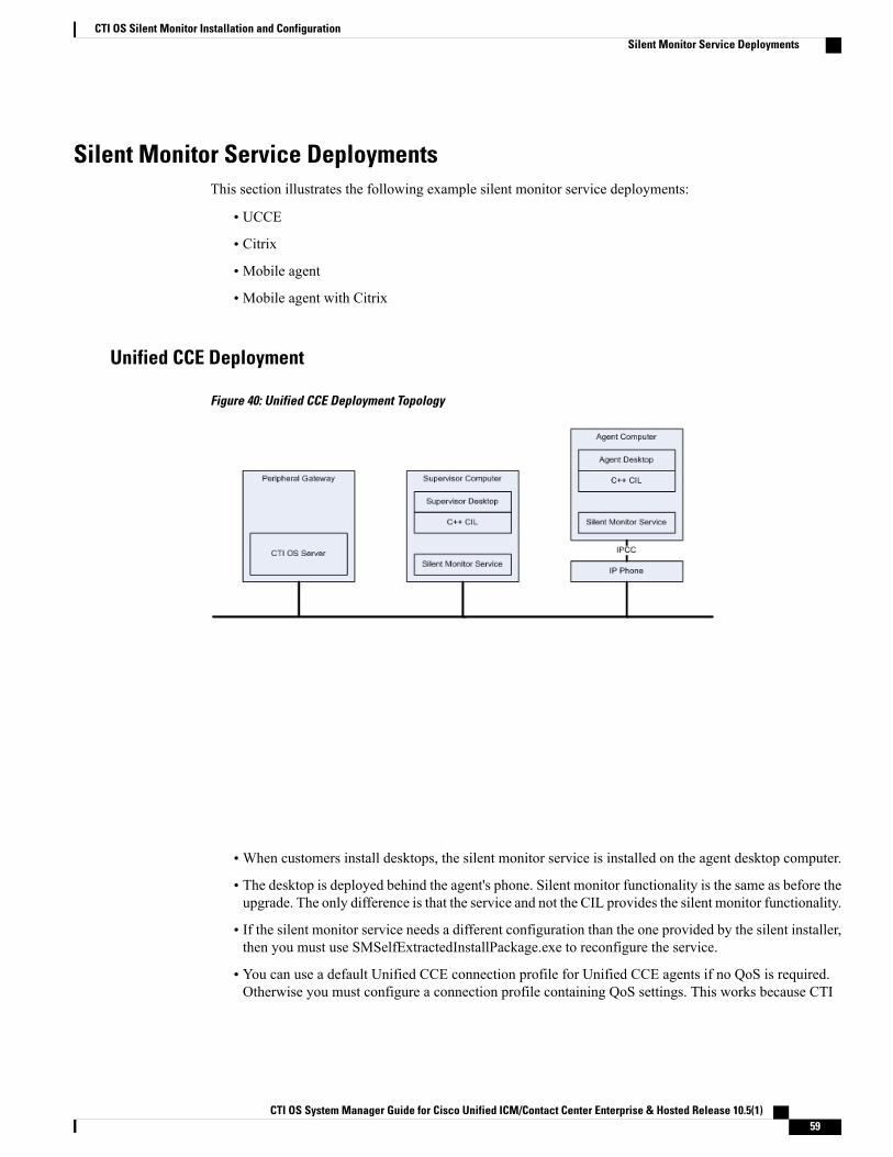
Silent Monitor Service DeploymentsThis section illustrates the following example silent monitor service deployments:
• UCCE
• Citrix
• Mobile agent
• Mobile agent with Citrix
Unified CCE Deployment
Figure 40: Unified CCE Deployment Topology
•When customers install desktops, the silent monitor service is installed on the agent desktop computer.
• The desktop is deployed behind the agent's phone. Silent monitor functionality is the same as before theupgrade. The only difference is that the service and not the CIL provides the silent monitor functionality.
• If the silent monitor service needs a different configuration than the one provided by the silent installer,then you must use SMSelfExtractedInstallPackage.exe to reconfigure the service.
• You can use a default Unified CCE connection profile for Unified CCE agents if no QoS is required.Otherwise you must configure a connection profile containing QoS settings. This works because CTI
CTI OS System Manager Guide for Cisco Unified ICM/Contact Center Enterprise & Hosted Release 10.5(1) 59
CTI OS Silent Monitor Installation and ConfigurationSilent Monitor Service Deployments
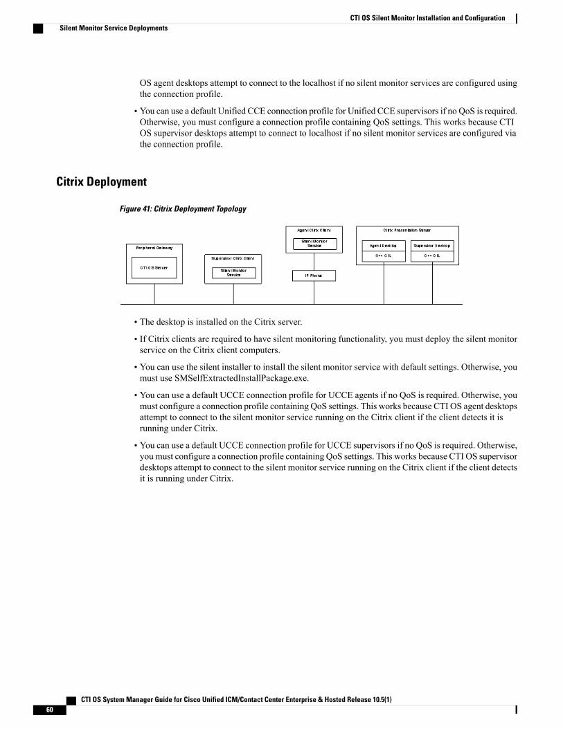
OS agent desktops attempt to connect to the localhost if no silent monitor services are configured usingthe connection profile.
• You can use a default Unified CCE connection profile for Unified CCE supervisors if no QoS is required.Otherwise, you must configure a connection profile containing QoS settings. This works because CTIOS supervisor desktops attempt to connect to localhost if no silent monitor services are configured viathe connection profile.
Citrix Deployment
Figure 41: Citrix Deployment Topology
• The desktop is installed on the Citrix server.
• If Citrix clients are required to have silent monitoring functionality, you must deploy the silent monitorservice on the Citrix client computers.
• You can use the silent installer to install the silent monitor service with default settings. Otherwise, youmust use SMSelfExtractedInstallPackage.exe.
• You can use a default UCCE connection profile for UCCE agents if no QoS is required. Otherwise, youmust configure a connection profile containing QoS settings. This works because CTI OS agent desktopsattempt to connect to the silent monitor service running on the Citrix client if the client detects it isrunning under Citrix.
• You can use a default UCCE connection profile for UCCE supervisors if no QoS is required. Otherwise,you must configure a connection profile containing QoS settings. This works because CTI OS supervisordesktops attempt to connect to the silent monitor service running on the Citrix client if the client detectsit is running under Citrix.
CTI OS System Manager Guide for Cisco Unified ICM/Contact Center Enterprise & Hosted Release 10.5(1)60
CTI OS Silent Monitor Installation and ConfigurationSilent Monitor Service Deployments
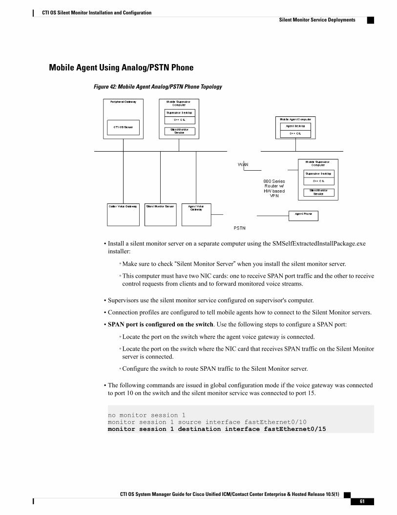
Mobile Agent Using Analog/PSTN Phone
Figure 42: Mobile Agent Analog/PSTN Phone Topology
• Install a silent monitor server on a separate computer using the SMSelfExtractedInstallPackage.exeinstaller:
◦Make sure to check “Silent Monitor Server” when you install the silent monitor server.
◦This computer must have two NIC cards: one to receive SPAN port traffic and the other to receivecontrol requests from clients and to forward monitored voice streams.
• Supervisors use the silent monitor service configured on supervisor's computer.
• Connection profiles are configured to tell mobile agents how to connect to the Silent Monitor servers.
• SPAN port is configured on the switch. Use the following steps to configure a SPAN port:
◦Locate the port on the switch where the agent voice gateway is connected.
◦Locate the port on the switch where the NIC card that receives SPAN traffic on the Silent Monitorserver is connected.
◦Configure the switch to route SPAN traffic to the Silent Monitor server.
• The following commands are issued in global configuration mode if the voice gateway was connectedto port 10 on the switch and the silent monitor service was connected to port 15.
no monitor session 1monitor session 1 source interface fastEthernet0/10monitor session 1 destination interface fastEthernet0/15
CTI OS System Manager Guide for Cisco Unified ICM/Contact Center Enterprise & Hosted Release 10.5(1) 61
CTI OS Silent Monitor Installation and ConfigurationSilent Monitor Service Deployments
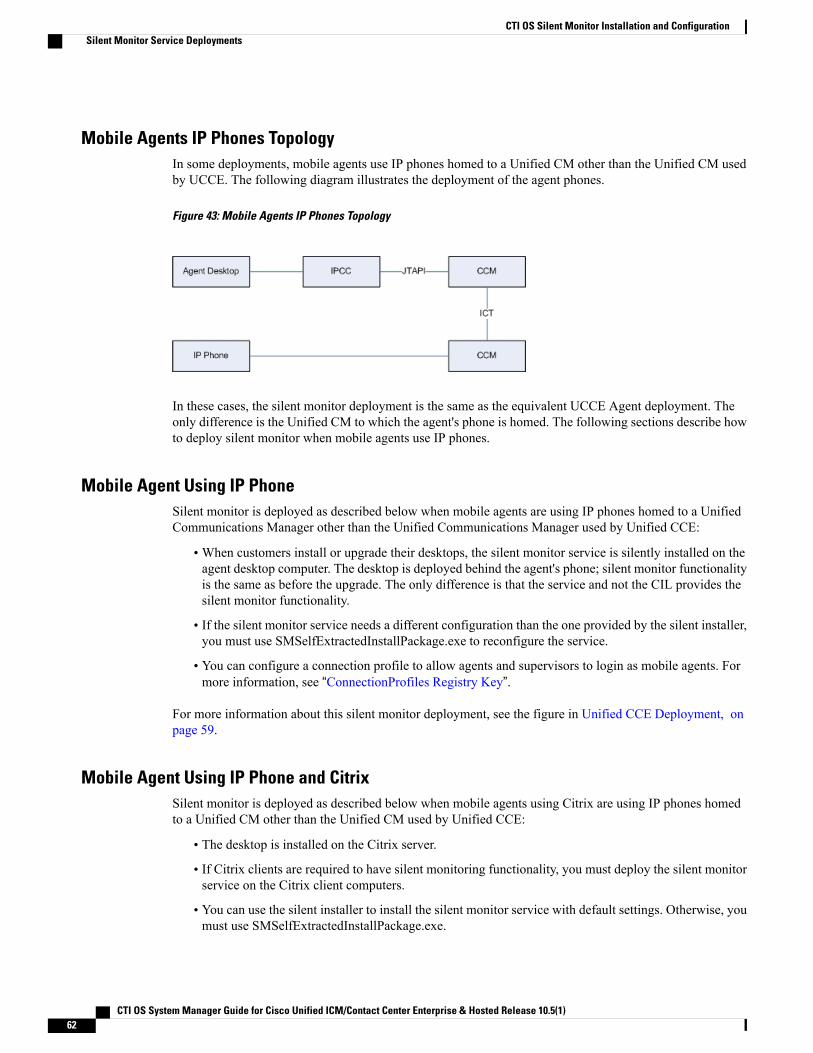
Mobile Agents IP Phones TopologyIn some deployments, mobile agents use IP phones homed to a Unified CM other than the Unified CM usedby UCCE. The following diagram illustrates the deployment of the agent phones.
Figure 43: Mobile Agents IP Phones Topology
In these cases, the silent monitor deployment is the same as the equivalent UCCE Agent deployment. Theonly difference is the Unified CM to which the agent's phone is homed. The following sections describe howto deploy silent monitor when mobile agents use IP phones.
Mobile Agent Using IP PhoneSilent monitor is deployed as described below when mobile agents are using IP phones homed to a UnifiedCommunications Manager other than the Unified Communications Manager used by Unified CCE:
•When customers install or upgrade their desktops, the silent monitor service is silently installed on theagent desktop computer. The desktop is deployed behind the agent's phone; silent monitor functionalityis the same as before the upgrade. The only difference is that the service and not the CIL provides thesilent monitor functionality.
• If the silent monitor service needs a different configuration than the one provided by the silent installer,you must use SMSelfExtractedInstallPackage.exe to reconfigure the service.
• You can configure a connection profile to allow agents and supervisors to login as mobile agents. Formore information, see “ConnectionProfiles Registry Key”.
For more information about this silent monitor deployment, see the figure in Unified CCE Deployment, onpage 59.
Mobile Agent Using IP Phone and CitrixSilent monitor is deployed as described below when mobile agents using Citrix are using IP phones homedto a Unified CM other than the Unified CM used by Unified CCE:
• The desktop is installed on the Citrix server.
• If Citrix clients are required to have silent monitoring functionality, you must deploy the silent monitorservice on the Citrix client computers.
• You can use the silent installer to install the silent monitor service with default settings. Otherwise, youmust use SMSelfExtractedInstallPackage.exe.
CTI OS System Manager Guide for Cisco Unified ICM/Contact Center Enterprise & Hosted Release 10.5(1)62
CTI OS Silent Monitor Installation and ConfigurationSilent Monitor Service Deployments
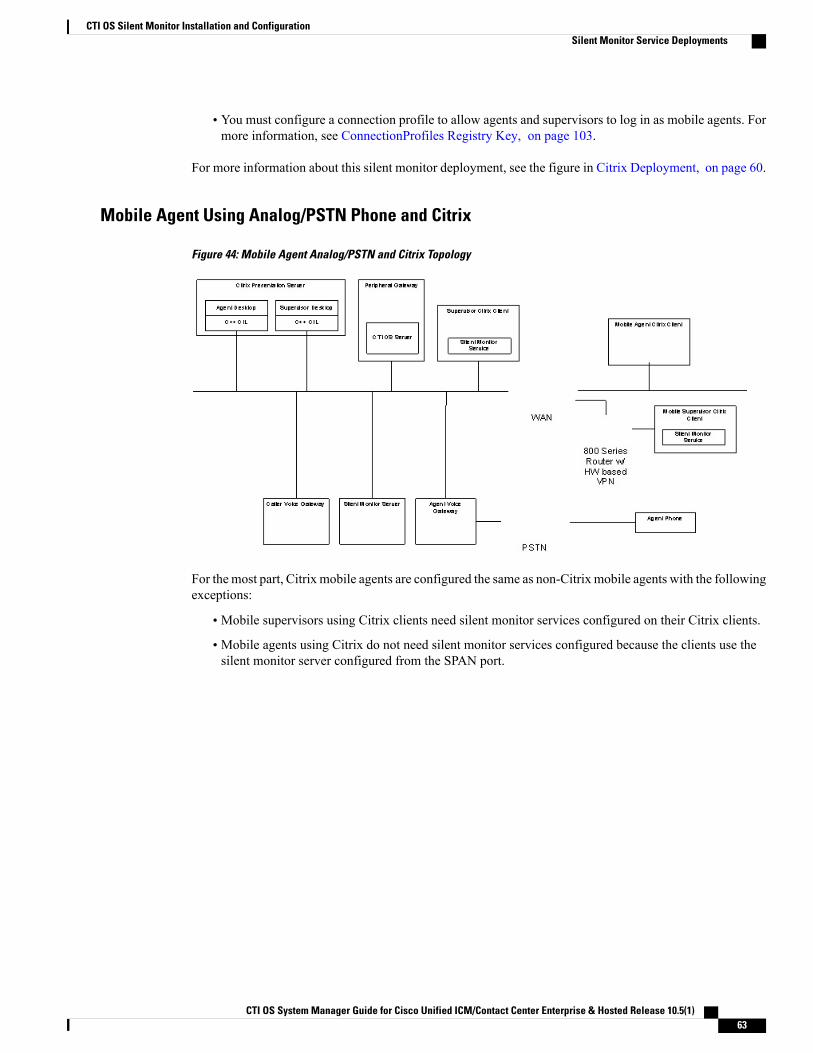
• You must configure a connection profile to allow agents and supervisors to log in as mobile agents. Formore information, see ConnectionProfiles Registry Key, on page 103.
For more information about this silent monitor deployment, see the figure in Citrix Deployment, on page 60.
Mobile Agent Using Analog/PSTN Phone and Citrix
Figure 44: Mobile Agent Analog/PSTN and Citrix Topology
For the most part, Citrix mobile agents are configured the same as non-Citrix mobile agents with the followingexceptions:
• Mobile supervisors using Citrix clients need silent monitor services configured on their Citrix clients.
• Mobile agents using Citrix do not need silent monitor services configured because the clients use thesilent monitor server configured from the SPAN port.
CTI OS System Manager Guide for Cisco Unified ICM/Contact Center Enterprise & Hosted Release 10.5(1) 63
CTI OS Silent Monitor Installation and ConfigurationSilent Monitor Service Deployments

CTI OS System Manager Guide for Cisco Unified ICM/Contact Center Enterprise & Hosted Release 10.5(1)64
CTI OS Silent Monitor Installation and ConfigurationSilent Monitor Service Deployments
C H A P T E R 5CTI OS Component Installation
• Silent Installation of CTI OS Components, page 65
• Uninstall Components, page 67
• Recover from Failed Installation of CTI OS, page 68
Silent Installation of CTI OS ComponentsCTI OS supports installation of some CTI OS components in unattended silent install mode. Silent install issupported for the following components:
• CTI OS Agent and Supervisor Desktops.
• CTI OS Agent and Supervisor Desktops under Citrix.
• CTI OS Server.
Silent install is not supported for the following components:
• CTI Driver for Siebel.
• Cisco Data Store.
CTI OS System Manager Guide for Cisco Unified ICM/Contact Center Enterprise & Hosted Release 10.5(1) 65
You must be aware of the following for CTI OS silent installation of the CTI OS agentand supervisor desktops:
Note
• You must install .NET 2.0 prior to silent installation.
• You can install only CTI OS agent and supervisor desktops of CTI OS Client; youcannot silently install other CTI OS Client installation options.
• Only fresh silent installation is supported. Youmust uninstall all previous versionsor patches of CTI OS Client prior to silently installing the CTI OS Client.
• Security is not installed when you install Client phones silently. If you needsecurity, run SecuritysetupPackage.exe from the installation CD after youcomplete the installation.
Silent uninstall is not supported for any CTI OS components.Note
The silent installation process involves two tasks:
• Creating a response file.
• Using the response file to run CTI OS silent install on other machines.
Use of silent installations is discouraged, as errors encountered during the install process may go unnoticedand leave the system in an invalid state. If you choose to run installations silently, be absolutely certainthat you manually perform the required pre- and post-installation instructions on the target systems.
Warning
Create a Response FileThe process of creating a response file for use with the CTI OS silent install installs all CTI OS components(CTI OS Agent Desktop, CTI OS Supervisor Desktop, CTI OS Server) that exist on the machine where theresponse file is recorded. To create a response file for use with the CTI OS silent install, perform the followingsteps.
Procedure
Step 1 From a command prompt, run the CTI OS installer with the following syntax:CTIOS7[1].1(1).exe –options-record "c:\mypath\myresponsefile.opt"
where c:\mypath\myresponsefile.opt is the complete path and filename that you want to give to the responsefile. The -options-record flag indicates that the install runs in record mode, which triggers the output of theresponse file. However, to create a response file the installer actually runs and installs the application on thesystem.
CTI OS System Manager Guide for Cisco Unified ICM/Contact Center Enterprise & Hosted Release 10.5(1)66
CTI OS Component InstallationCreate a Response File
For release 9.0(1) on a Windows Server 2008 R2 system, run setup from a command prompt withthe following option: setup.exe /r. This outputs a file called setup.iss to the <drive>:\icm directory.When the installer completes, examine the setup log file to verify that the installation is completewith no errors.
Note
Step 2 After the installation is complete, examine the setup log file to verify that installation ran to completion withno errors.
It is critical that you verify that the installation process ran successfully and created a valid responsefile. Running the CTI OS silent install with an invalid response file can leave your system in aninvalid state.
Caution
Step 3 Reboot your system.
Run CTI OS Silent Install on Other MachinesAfter you create a response file on one machine, you can use that response file to run the CTI OS silent installon other machines. To do this, perform the following steps.
Procedure
Step 1 Copy the response file to the machine(s) on which you wish to run CTI OS silent install.Step 2 From a command prompt, run the CTI OS installer with the following syntax:
CTIOS7[1].1(1).exe –options "c:\mypath\myresponsefile.opt" -silent
where c:\mypath\myresponsefile.opt is the complete path and filename for the response file. The -silent flagindicates that the installation runs in silent mode.
For Release 9.0(1), copy the setup.iss file created above to the same directory where setup.exe islocated, and then run the setup with the following syntax: setup.exe /s.
Note
Step 3 When the installation is complete, examine the setup log file to verify that installation ran to completion withno errors.
It is critical that you verify that the installation process ran successfully and created a valid responsefile. Running CTI OS silent install with an invalid response file can leave your system in an invalidstate.
Caution
Step 4 Reboot your system.
Uninstall ComponentsTo uninstall the CTI OS components, rerun the Setup program for the previous release and delete the UnifiedICM Customer Instance that you specified during CTI OS component setup.
CTI OS System Manager Guide for Cisco Unified ICM/Contact Center Enterprise & Hosted Release 10.5(1) 67
CTI OS Component InstallationRun CTI OS Silent Install on Other Machines
Recover from Failed Installation of CTI OSIf an attempted CTI OS installation fails for reasons such as power failure, disk error, or other similarcircumstances, perform the following procedures to recover from the failed installation.
Procedure
Step 1 Uninstall the release, as documented in Uninstall Components.Step 2 Reinstall the release by performing the procedures documented in the following sections:
• Install CTI OS Server, on page 14.
• Run Silent Monitor Service Installer, on page 50.
• Additional Configuration Steps, on page 55.
CTI OS System Manager Guide for Cisco Unified ICM/Contact Center Enterprise & Hosted Release 10.5(1)68
CTI OS Component InstallationRecover from Failed Installation of CTI OS
C H A P T E R 6Unified Communications Manager-Based SilentMonitor Configuration
• Unified CM Silent Monitor Configuration and Administration, page 69
• CTI OS and Silent Monitoring, page 74
• Restrictions, page 75
Unified CM Silent Monitor Configuration and AdministrationThis section describes how to configure devices and JTAPI users on Unified CM to enable silent monitoring.
CTI OS System Manager Guide for Cisco Unified ICM/Contact Center Enterprise & Hosted Release 10.5(1) 69
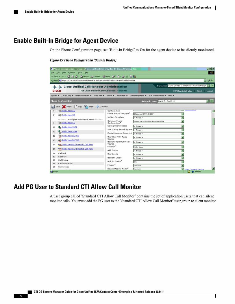
Enable Built-In Bridge for Agent DeviceOn the Phone Configuration page, set “Built-In Bridge” to On for the agent device to be silently monitored.
Figure 45: Phone Configuration (Built-In Bridge)
Add PG User to Standard CTI Allow Call MonitorA user group called “Standard CTI Allow Call Monitor” contains the set of application users that can silentmonitor calls. You must add the PG user to the “Standard CTI Allow Call Monitor” user group to silent monitor
CTI OS System Manager Guide for Cisco Unified ICM/Contact Center Enterprise & Hosted Release 10.5(1)70
Unified Communications Manager-Based Silent Monitor ConfigurationEnable Built-In Bridge for Agent Device
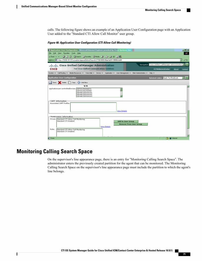
calls. The following figure shows an example of an Application User Configuration page with an ApplicationUser added to the “Standard CTI Allow Call Monitor” user group.
Figure 46: Application User Configuration (CTI Allow Call Monitoring)
Monitoring Calling Search SpaceOn the supervisor's line appearance page, there is an entry for “Monitoring Calling Search Space”. Theadministrator enters the previously created partition for the agent that can be monitored. The MonitoringCalling Search Space on the supervisor's line appearance page must include the partition to which the agent'sline belongs.
CTI OS System Manager Guide for Cisco Unified ICM/Contact Center Enterprise & Hosted Release 10.5(1) 71
Unified Communications Manager-Based Silent Monitor ConfigurationMonitoring Calling Search Space
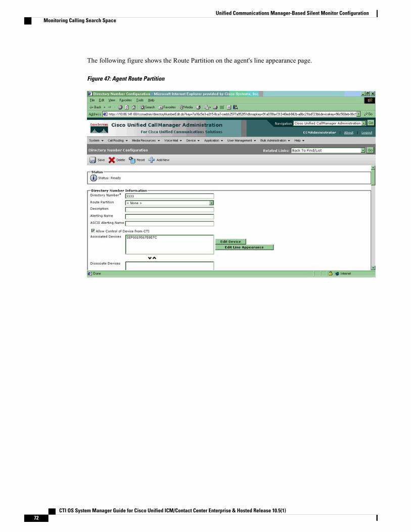
The following figure shows the Route Partition on the agent's line appearance page.
Figure 47: Agent Route Partition
CTI OS System Manager Guide for Cisco Unified ICM/Contact Center Enterprise & Hosted Release 10.5(1)72
Unified Communications Manager-Based Silent Monitor ConfigurationMonitoring Calling Search Space
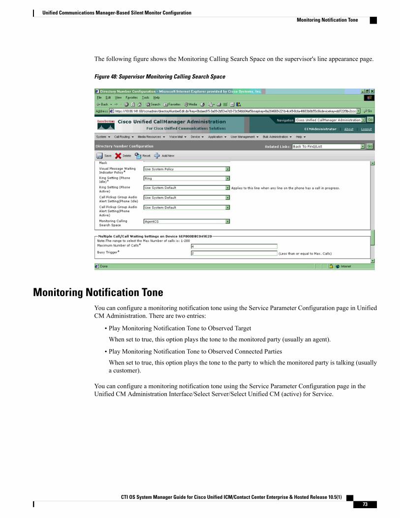
The following figure shows the Monitoring Calling Search Space on the supervisor's line appearance page.
Figure 48: Supervisor Monitoring Calling Search Space
Monitoring Notification ToneYou can configure a monitoring notification tone using the Service Parameter Configuration page in UnifiedCM Administration. There are two entries:
• Play Monitoring Notification Tone to Observed Target
When set to true, this option plays the tone to the monitored party (usually an agent).
• Play Monitoring Notification Tone to Observed Connected Parties
When set to true, this option plays the tone to the party to which the monitored party is talking (usuallya customer).
You can configure a monitoring notification tone using the Service Parameter Configuration page in theUnified CM Administration Interface/Select Server/Select Unified CM (active) for Service.
CTI OS System Manager Guide for Cisco Unified ICM/Contact Center Enterprise & Hosted Release 10.5(1) 73
Unified Communications Manager-Based Silent Monitor ConfigurationMonitoring Notification Tone
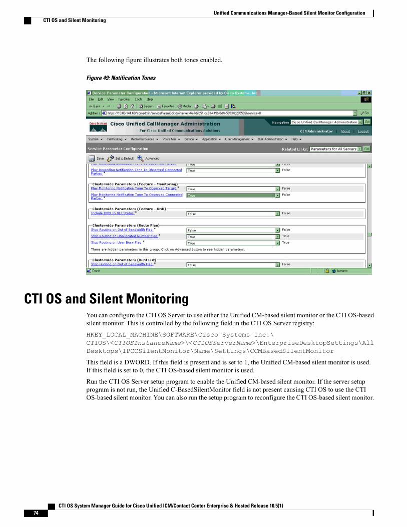
The following figure illustrates both tones enabled.
Figure 49: Notification Tones
CTI OS and Silent MonitoringYou can configure the CTI OS Server to use either the Unified CM-based silent monitor or the CTI OS-basedsilent monitor. This is controlled by the following field in the CTI OS Server registry:
HKEY_LOCAL_MACHINE\SOFTWARE\Cisco Systems Inc.\CTIOS\<CTIOSInstanceName>\<CTIOSServerName>\EnterpriseDesktopSettings\AllDesktops\IPCCSilentMonitor\Name\Settings\CCMBasedSilentMonitor
This field is a DWORD. If this field is present and is set to 1, the Unified CM-based silent monitor is used.If this field is set to 0, the CTI OS-based silent monitor is used.
Run the CTI OS Server setup program to enable the Unified CM-based silent monitor. If the server setupprogram is not run, the Unified C-BasedSilentMonitor field is not present causing CTI OS to use the CTIOS-based silent monitor. You can also run the setup program to reconfigure the CTI OS-based silent monitor.
CTI OS System Manager Guide for Cisco Unified ICM/Contact Center Enterprise & Hosted Release 10.5(1)74
Unified Communications Manager-Based Silent Monitor ConfigurationCTI OS and Silent Monitoring
Restrictions
PhonesThe Unified Communications Manager silent monitoring only supports Cisco IP Phones that have a Built-InBridge (BIB). See the Unified CCECompatibilityMatrix for a list of supported phones. Deployments withoutthese phones or deployments with mobile agents must use the CTI OS-based silent monitor.
Cisco Unified CMCisco Unified CM is required.
CTI OS Desktop VersionsThe CTI OS Server and CTI OS desktop versions cannot be higher than the Central Controller version. Formore information about server compatibility, see the Compatibility Matrix for Unified CCE at http://docwiki.cisco.com/wiki/Compatibility_Matrix_for_Unified_CCE.
Recording ApplicationsRecording applications record agent conversations. Recording applications do not interfere with silentmonitoring.
Transfer and Conferencing of Monitored CallsSupervisors cannot transfer or conference silent monitor calls because these functions are not supported.
CTI OS System Manager Guide for Cisco Unified ICM/Contact Center Enterprise & Hosted Release 10.5(1) 75
Unified Communications Manager-Based Silent Monitor ConfigurationRestrictions

CTI OS System Manager Guide for Cisco Unified ICM/Contact Center Enterprise & Hosted Release 10.5(1)76
Unified Communications Manager-Based Silent Monitor ConfigurationTransfer and Conferencing of Monitored Calls
C H A P T E R 7CTI OS Security
This chapter provides information about configuring the CTI OS Security Certificate and the SecurityCompatibility.
• CTI OS Security Certificate Configuration, page 77
• CTI OS Security Registry Keys, page 81
• Security Compatibility, page 83
CTI OS Security Certificate ConfigurationThe CTI OS Security Certificate comprises the following:
• CTI OS Security Setup programs.
• Signing CTI Toolkit Desktop Client Certificate Request with Self-Signed Certificate Authority (CA).
• Signing CTI OS Server Certificate Request with Self-Signed CA.
• Signing CTI Toolkit Desktop Client Certificate Request with Third-Party CA.
• Signing CTI OS Server Certificate Request with Third-Party CA.
Each of these entities is detailed in this section.
Both Certificate Revocation List (CRL) and certificate chain are not supported in CTI OS Security.Note
CTI OS Security Setup ProgramsTo configure the CTI OS, three setup programs are implemented. These setup programs are part of the Win32CTI OS toolkit installation, and are located in the directory <drive>:\Program Files\CiscoSystems\CTIOS Client\CTIOS Security\Utilities.
The first setup program, CreateSelfSignedCASetupPackage.exe, creates a self-signed certificate authority(CA). This must be run once if the customer wants to use a self-signed CA instead of a third party and the
CTI OS System Manager Guide for Cisco Unified ICM/Contact Center Enterprise & Hosted Release 10.5(1) 77

output of CreateSelfSignedCASetupPackage.exe must be saved in a secure place. This program createsCA-related files. One file, CtiosRoot.pem, contains the private CA information. This file must be kept in asafe place. Another file, CtiosRootCert.pem, contains public CA information. This setup program asks theuser to enter a password for the CA (between 8 and 30 characters), which are used when signing CTI OScertificate requests.
The second setup program, SecuritySetupPackage.exe, is used to generate certificate requests for both CTIToolkit Desktop Client and CTI OS Server. If the certificate request is for the CTI OS Server, then it generatesCtiosServerKey.pem, and CtiosServerReq.pem. These files are used when signing server certificates. If thecertificate request is for the CTI Toolkit Desktop Client, then it generates CtiosClientkey.pem, andCtiosClientreq.pem. These files are used when signing client certificates.
The third setup program, SignCertificateSetupPackage.exe. is used to sign both CTI Toolkit Desktop Clientand CTI OS Server certificates. This program is used only when the customer decides to sign their CTI ToolkitDesktop Client and CTI OS Server certificates with self signed CA. This program must reside in the samedirectory as the CtiosRootCert.pem and CtiosRoot.pem. If the certificate that is going to be signed is for theclient, it generates CtiosClient.pem file. If the certificate that is going to be signed is for the server, it generatesCtiosServer.pem file. This program asks the user to enter the following information:
• Ctios Certificate Authority Password. This password is the one used to create a self-signed CA.
• Select either CTI Toolkit Desktop Client Certificate Request or CTI OS Server Certificate Request.
•
Sign CTI Toolkit Desktop Client Certificate Request with Self-Signed CAFollow these steps to sign a CTI Toolkit Desktop Client certificate request.
Procedure
Step 1 If the self-signed CA does not exist, then run CreateSelfSignedCASetupPackage.exe and store all the filesthat were created by the CreateSelfSignedCASetupPackage.exe program in a safe place. This step generatesCtiosRoot.pem and CtiosRootCert.pem in the same folder from where the setup is run.
Step 2 Copy CtiosClientkey.pem and CtiosClientreq.pem files from the CTI Toolkit Desktop Client machine to themachine where CtiosRoot.pem and CtiosRootCert.pem reside.
You must Copy the Ctiosclientkey.pem and CtiosClientreq.pem files from the CTI Toolkit DesktopClient machine under <drive>:\Program Files\Cisco Systems\CTIOSClient\CTIOS Security to the folder where CtiosRoot.pem and CtiosRootCert.pem resides.
Note
Step 3 Run SignCertificateSetupPackage.exe from the same directory where CtiosClientkey.pem, CtiosClientreq.pem,CtiosRoot.pem, and CtiosRootCert.pem reside, select CTIOS Client Certificate Request, and enter the “CtiosCertificate Authority password.”This step generates the file CtiosClient.pem if it is successful; otherwise it displays an error message.
Step 4 Copy both CtiosClient.pem and CtiosRootCert.pem back to the machine where CTI Toolkit Desktop Clientis installed and save them in the <drive>:\Program Files\Cisco Systems\CTIOSClient\CTIOS Security directory.
Step 5 DeleteCtiosClientkey.pem in<drive>:\Program Files\Cisco Systems\CTIOS Client\CTIOSSecurity\Utilities directory from the machine where CTI Toolkit Desktop Client is installed.
Step 6 Delete CtiosClientkey.pem, CtiosClientreq.pem, and CtiosClient.pem from the machine whereSignCertificateSetupPackage.exe ran.
CTI OS System Manager Guide for Cisco Unified ICM/Contact Center Enterprise & Hosted Release 10.5(1)78
CTI OS SecuritySign CTI Toolkit Desktop Client Certificate Request with Self-Signed CA
Sign CTI OS Server Certificate Request with Self-Signed CAFollow these steps to sign a CTI OS Server certificate request.
Procedure
Step 1 If the self-signed CA does not exist, then run CreateSelfSignedCASetupPackage.exe and store all the filesthat were created by the CreateSelfSignedCASetupPackage.exe program in a safe place. This step generatesCtiosRoot.pem and CtiosRootCert.pem in the same folder from where the setup is run.
Step 2 Copy CtiosServerKey.pem and CtiosServerReq.pem files from the CTI OS Server machine to the machinewhere CtiosRoot.pem and CtiosRootCert.pem reside.
You must copy both CtiosServerKey.pem and CtiosServerReq.pem files from the CTI OS servermachine under <drive>:\icm\Instance name\CTIOS1\Security to the same directoryas CtiosRoot.pem and CtiosRootCert.pem.
Note
Step 3 Run SignCertificateSetupPackage.exe from the same directory where CtiosServerKey.pem,CtiosServerReq.pem, CtiosRoot.pem, and CtiosRootCert.pem reside, select CTIOS Server Certificate Request,and enter the “Ctios Certificate Authority password.”This step generates CtiosServer.pem file if it is successful; otherwise it displays an error message.
Step 4 Copy both CtiosServer.pem and CtiosRootCert.pem back to the machine where CTI OS Server resides andsave them in the <drive>:\icm\Instance name\CTIOS1\Security directory.
Step 5 Delete CtiosServerkey.pem under <drive>:\icm\Instance name\CTIOS1\Security from themachine where CTI OS Server is installed.
Step 6 Delete CtiosServerKey.pem, CtiosServerReq.pem, and CtiosServer.pem from the machine whereSignCertificateSetupPackage.exe ran.
Step 7 If CTIOS Server has peer server, then:a) Copy CtiosClientkey.pem and CtiosClientreq.pem files from the CTI OS Server machine to the machine
where CtiosRoot.pem and CtiosRootCert.pem reside. You must copy both CtiosClientkey.pem andCtiosClientreq.pem files to the same directory as CtiosRoot.pem and CtiosRootCert.pem.
b) Run SignCertificateSetupPackage.exe from the same directory where CtiosClientkey.pem,CtiosClientreq.pem, CtiosRoot.pem, and CtiosRootCert.pem reside, select CTI Toolkit Desktop ClientCertificate Request, and enter the “Ctios Certificate Authority password.” This step generatesCtiosClient.pem file if it is successful; otherwise it displays an error message.
c) Copy CtiosClient.pem to the machine where CTI OS Server resides and save it in<drive>:\icm\<Instance name>\CTIOS1\Security directory.
d) Delete CtiosClientkey.pem from the machine where CTI OS Server is installed.e) Delete CtiosClientkey.pem, CtiosClientreq.pem, and CtiosClient.pem from the machine where
SignCertificateSetupPackage.exe ran.
CTI OS System Manager Guide for Cisco Unified ICM/Contact Center Enterprise & Hosted Release 10.5(1) 79
CTI OS SecuritySign CTI OS Server Certificate Request with Self-Signed CA
Sign CTI Toolkit Desktop Client Certificate Request with Third-Party CA
Procedure
Step 1 CopyCtiosClientreq.pem file from the CTI Toolkit Desktop Client machine to themachinewhere the third-partyCA resides.
Step 2 Signing CTI Toolkit Desktop Client certificate request (CtiosClientreq.pem) with third-party CA generates aCTI Toolkit Desktop Client certificate. Rename it CtiosClientCert.pem.
Step 3 The third-party CA has its certificate public information in a file. Rename this file CtiosRootCert.pem.Step 4 Copy both CtiosClientCert.pem and CtiosRootCert.pem to the machine where CTI Toolkit Desktop Client
resides and save them in the <drive>:\Program Files\Cisco Systems\CTIOSClient\Security directory.
Step 5 On the CTI Toolkit Desktop Client machine, copy the data in CtiosClientCert.pem and the data inCtiosClientkey.pem files into one file called CtiosClient.pem. The order is very important, so CtiosClient.pemmust contain CtiosClientCert.pem data first and then CtiosClientkey.pem data second.
Step 6 Delete CtiosClientCert.pem and CtiosClientkey.pem from the CTI Toolkit Desktop Client machine.
Sign CTI OS Server Certificate Request with Third-Party CAFollow these steps to sign a CTI OS Server certificate request.
Procedure
Step 1 Copy CtiosServerReq.pem file from the CTI OS Server machine to the machine where the third-party CAresides.
Step 2 Signing CTI OS Server certificate request (CtiosServerReq.pem) with third-party CA generates a CTI OSServer certificate. Rename it CtiosServerCert.pem.
Step 3 The third-party CA has its certificate public information in a file. Rename this file CtiosRootCert.pem.Step 4 Copy both CtiosServerCert.pem and CtiosRootCert.pem to the machine where CTI OS Server resides and
save them in the <drive>:\icm\<Instance name>\CTIOS1\Security directory.Step 5 On the CTI OS Server machine, copy the data in CtiosServerCert.pem and the data in CtiosServerkey.pem
files into one file called CtiosServer.pem. The order is very important, so CtiosServer.pem must containCtiosServerCert.pem data first and then CtiosServerkey.pem data second.
Step 6 Delete CtiosServerCert.pem and CtiosServerkey.pem from the CTI OS Server machine.Step 7 If CTIOS Server has peer server, then:
a) Copy CtiosClientreq.pem file from the CTI OS Server machine to the machine where the third party CAresides.
b) Signing CTI Toolkit Desktop Client certificate request (CtiosClientreq.pem)with third party CA generatesa CTI Toolkit Desktop Client certificate. Rename it CtiosClientCert.pem.
c) Copy CtiosClientCert.pem file to the machine where CTI OS Server resides and save it in the<drive>:\icm\<Instance name>\CTIOS1\Security directory.
CTI OS System Manager Guide for Cisco Unified ICM/Contact Center Enterprise & Hosted Release 10.5(1)80
CTI OS SecuritySign CTI Toolkit Desktop Client Certificate Request with Third-Party CA
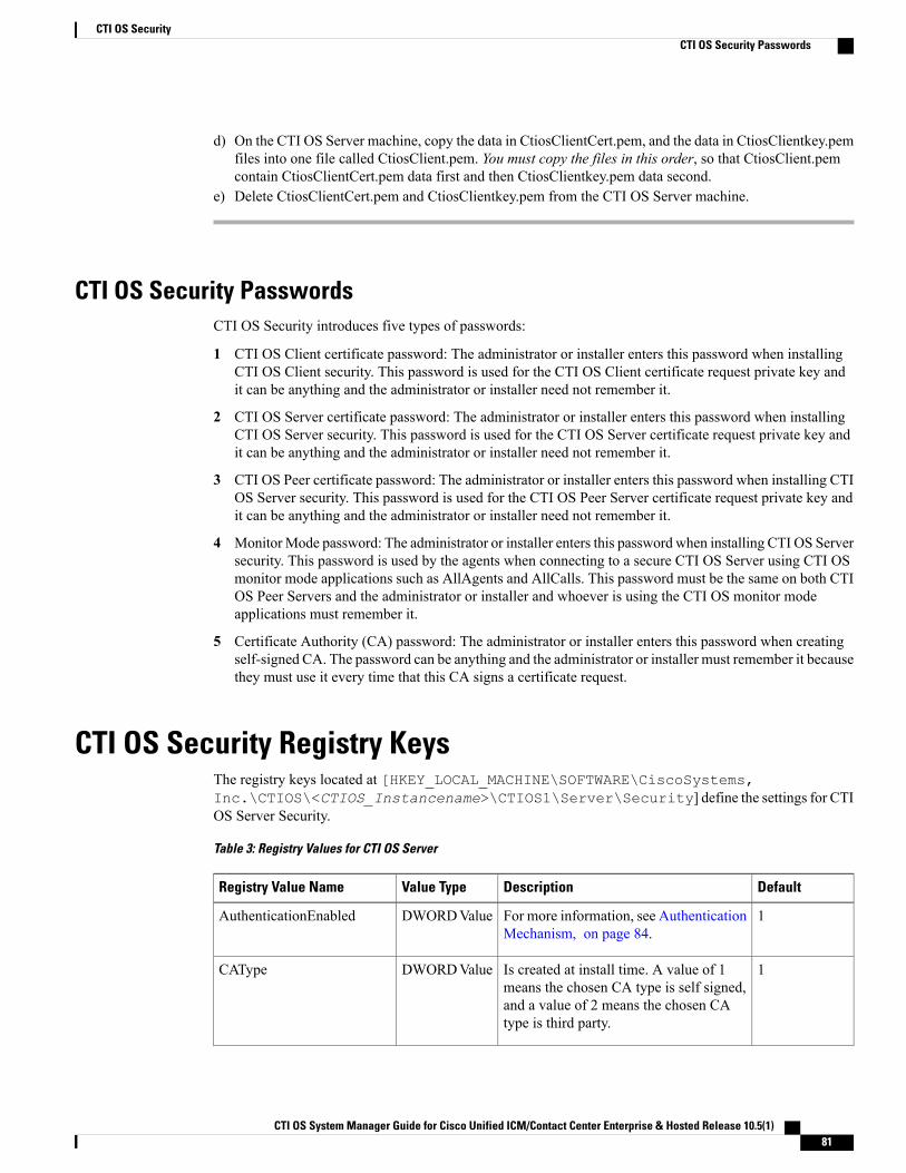
d) On the CTI OS Server machine, copy the data in CtiosClientCert.pem, and the data in CtiosClientkey.pemfiles into one file called CtiosClient.pem. You must copy the files in this order, so that CtiosClient.pemcontain CtiosClientCert.pem data first and then CtiosClientkey.pem data second.
e) Delete CtiosClientCert.pem and CtiosClientkey.pem from the CTI OS Server machine.
CTI OS Security PasswordsCTI OS Security introduces five types of passwords:
1 CTI OS Client certificate password: The administrator or installer enters this password when installingCTI OS Client security. This password is used for the CTI OS Client certificate request private key andit can be anything and the administrator or installer need not remember it.
2 CTI OS Server certificate password: The administrator or installer enters this password when installingCTI OS Server security. This password is used for the CTI OS Server certificate request private key andit can be anything and the administrator or installer need not remember it.
3 CTI OS Peer certificate password: The administrator or installer enters this password when installing CTIOS Server security. This password is used for the CTI OS Peer Server certificate request private key andit can be anything and the administrator or installer need not remember it.
4 MonitorMode password: The administrator or installer enters this password when installing CTI OS Serversecurity. This password is used by the agents when connecting to a secure CTI OS Server using CTI OSmonitor mode applications such as AllAgents and AllCalls. This password must be the same on both CTIOS Peer Servers and the administrator or installer and whoever is using the CTI OS monitor modeapplications must remember it.
5 Certificate Authority (CA) password: The administrator or installer enters this password when creatingself-signed CA. The password can be anything and the administrator or installer must remember it becausethey must use it every time that this CA signs a certificate request.
CTI OS Security Registry KeysThe registry keys located at [HKEY_LOCAL_MACHINE\SOFTWARE\CiscoSystems,Inc.\CTIOS\<CTIOS_Instancename>\CTIOS1\Server\Security] define the settings for CTIOS Server Security.
Table 3: Registry Values for CTI OS Server
DefaultDescriptionValue TypeRegistry Value Name
1For more information, see AuthenticationMechanism, on page 84.
DWORDValueAuthenticationEnabled
1Is created at install time. A value of 1means the chosen CA type is self signed,and a value of 2 means the chosen CAtype is third party.
DWORDValueCAType
CTI OS System Manager Guide for Cisco Unified ICM/Contact Center Enterprise & Hosted Release 10.5(1) 81
CTI OS SecurityCTI OS Security Passwords
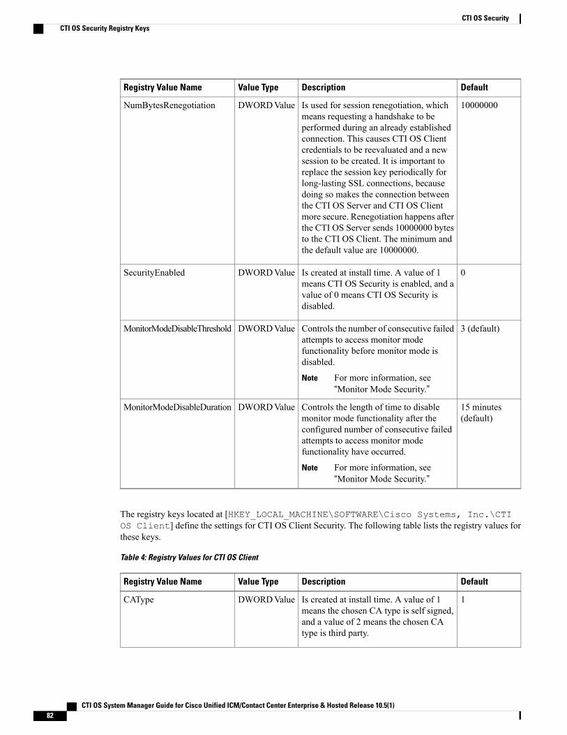
DefaultDescriptionValue TypeRegistry Value Name
10000000Is used for session renegotiation, whichmeans requesting a handshake to beperformed during an already establishedconnection. This causes CTI OS Clientcredentials to be reevaluated and a newsession to be created. It is important toreplace the session key periodically forlong-lasting SSL connections, becausedoing so makes the connection betweenthe CTI OS Server and CTI OS Clientmore secure. Renegotiation happens afterthe CTI OS Server sends 10000000 bytesto the CTI OS Client. The minimum andthe default value are 10000000.
DWORDValueNumBytesRenegotiation
0Is created at install time. A value of 1means CTI OS Security is enabled, and avalue of 0 means CTI OS Security isdisabled.
DWORDValueSecurityEnabled
3 (default)Controls the number of consecutive failedattempts to access monitor modefunctionality before monitor mode isdisabled.
For more information, see“Monitor Mode Security.”
Note
DWORDValueMonitorModeDisableThreshold
15 minutes(default)
Controls the length of time to disablemonitor mode functionality after theconfigured number of consecutive failedattempts to access monitor modefunctionality have occurred.
For more information, see“Monitor Mode Security.”
Note
DWORDValueMonitorModeDisableDuration
The registry keys located at [HKEY_LOCAL_MACHINE\SOFTWARE\Cisco Systems, Inc.\CTIOS Client] define the settings for CTI OS Client Security. The following table lists the registry values forthese keys.
Table 4: Registry Values for CTI OS Client
DefaultDescriptionValue TypeRegistry Value Name
1Is created at install time. A value of 1means the chosen CA type is self signed,and a value of 2 means the chosen CAtype is third party.
DWORDValueCAType
CTI OS System Manager Guide for Cisco Unified ICM/Contact Center Enterprise & Hosted Release 10.5(1)82
CTI OS SecurityCTI OS Security Registry Keys
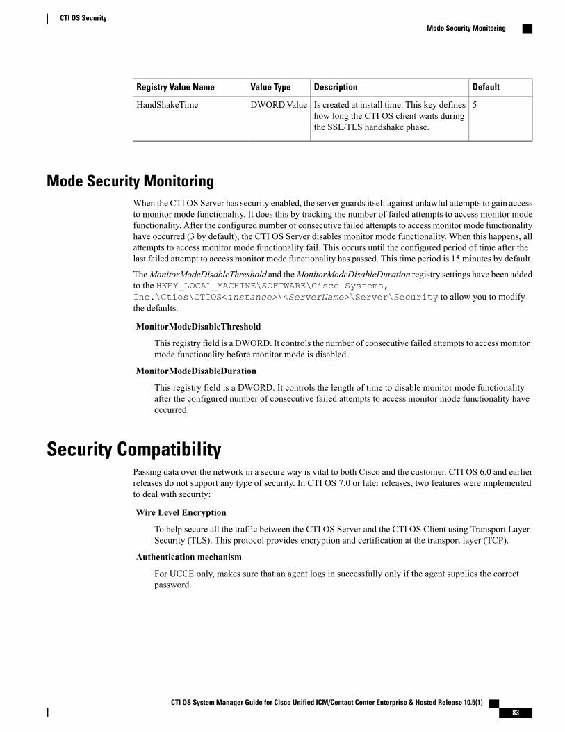
DefaultDescriptionValue TypeRegistry Value Name
5Is created at install time. This key defineshow long the CTI OS client waits duringthe SSL/TLS handshake phase.
DWORDValueHandShakeTime
Mode Security MonitoringWhen the CTI OS Server has security enabled, the server guards itself against unlawful attempts to gain accessto monitor mode functionality. It does this by tracking the number of failed attempts to access monitor modefunctionality. After the configured number of consecutive failed attempts to access monitor mode functionalityhave occurred (3 by default), the CTI OS Server disables monitor mode functionality. When this happens, allattempts to access monitor mode functionality fail. This occurs until the configured period of time after thelast failed attempt to access monitor mode functionality has passed. This time period is 15 minutes by default.
TheMonitorModeDisableThreshold and theMonitorModeDisableDuration registry settings have been addedto the HKEY_LOCAL_MACHINE\SOFTWARE\Cisco Systems,Inc.\Ctios\CTIOS<instance>\<ServerName>\Server\Security to allow you to modifythe defaults.
MonitorModeDisableThreshold
This registry field is a DWORD. It controls the number of consecutive failed attempts to access monitormode functionality before monitor mode is disabled.
MonitorModeDisableDuration
This registry field is a DWORD. It controls the length of time to disable monitor mode functionalityafter the configured number of consecutive failed attempts to access monitor mode functionality haveoccurred.
Security CompatibilityPassing data over the network in a secure way is vital to both Cisco and the customer. CTI OS 6.0 and earlierreleases do not support any type of security. In CTI OS 7.0 or later releases, two features were implementedto deal with security:
Wire Level Encryption
To help secure all the traffic between the CTI OS Server and the CTI OS Client using Transport LayerSecurity (TLS). This protocol provides encryption and certification at the transport layer (TCP).
Authentication mechanism
For UCCE only, makes sure that an agent logs in successfully only if the agent supplies the correctpassword.
CTI OS System Manager Guide for Cisco Unified ICM/Contact Center Enterprise & Hosted Release 10.5(1) 83
CTI OS SecurityMode Security Monitoring
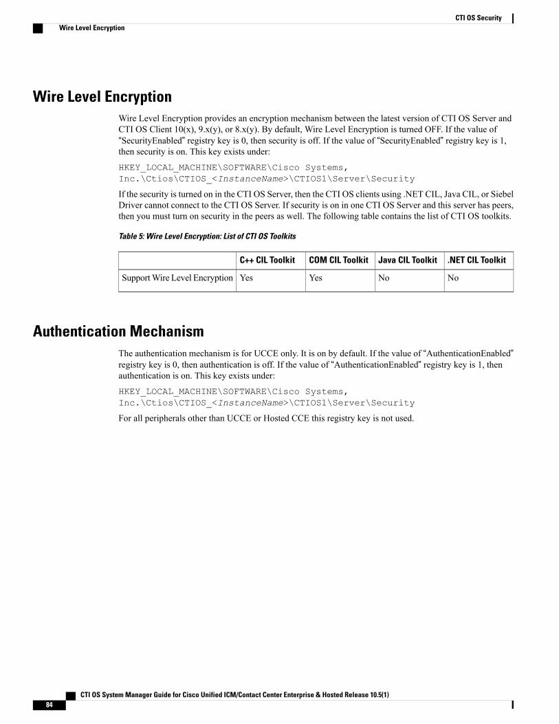
Wire Level EncryptionWire Level Encryption provides an encryption mechanism between the latest version of CTI OS Server andCTI OS Client 10(x), 9.x(y), or 8.x(y). By default, Wire Level Encryption is turned OFF. If the value of“SecurityEnabled” registry key is 0, then security is off. If the value of “SecurityEnabled” registry key is 1,then security is on. This key exists under:
HKEY_LOCAL_MACHINE\SOFTWARE\Cisco Systems,Inc.\Ctios\CTIOS_<InstanceName>\CTIOS1\Server\Security
If the security is turned on in the CTI OS Server, then the CTI OS clients using .NET CIL, Java CIL, or SiebelDriver cannot connect to the CTI OS Server. If security is on in one CTI OS Server and this server has peers,then you must turn on security in the peers as well. The following table contains the list of CTI OS toolkits.
Table 5: Wire Level Encryption: List of CTI OS Toolkits
.NET CIL ToolkitJava CIL ToolkitCOM CIL ToolkitC++ CIL Toolkit
NoNoYesYesSupportWire Level Encryption
Authentication MechanismThe authentication mechanism is for UCCE only. It is on by default. If the value of “AuthenticationEnabled”registry key is 0, then authentication is off. If the value of “AuthenticationEnabled” registry key is 1, thenauthentication is on. This key exists under:
HKEY_LOCAL_MACHINE\SOFTWARE\Cisco Systems,Inc.\Ctios\CTIOS_<InstanceName>\CTIOS1\Server\Security
For all peripherals other than UCCE or Hosted CCE this registry key is not used.
CTI OS System Manager Guide for Cisco Unified ICM/Contact Center Enterprise & Hosted Release 10.5(1)84
CTI OS SecurityWire Level Encryption
C H A P T E R 8CTI OS Configuration
CTI OS configuration is handled through the Windows Registry Editor. Using the Editor, you can add orchange registry values. This chapter provides instructions for working with the Windows Registry Editorand discusses the required values for the CTI OS registry keys.
This chapter does not discuss configuration of CTI OSClient registry values that the CTI OSClient downloadsfrom the CTI OS Server upon client login. For more information about CTI OS Client logging and tracingregistry values, see Appendix B of the CTI OS Developer's Guide for Cisco Unified ICM/Contact CenterEnterprise & Hosted.
Except where otherwise indicated, the CTI OS registry keys discussed in this chapter are local and startat the [HKEY_LOCAL_MACHINE\SOFTWARE\ Cisco Systems,Inc.\CTIOS\<CTIOS_CTIOSInstanceName>\<CTIOSServerName>] path.
Note
• Use Windows Registry Editor, page 86
• Virtual Desktop Infrastructure, page 88
• CTI Driver Key, page 89
• EMS Tracing Values, page 90
• Server Registry Key, page 92
• MainScreen Registry Key, page 101
• UCCE Silent Monitor Configuration, page 102
• ConnectionProfiles Registry Key, page 103
• Call Appearance Grid Configuration, page 109
• Customize Agent Statistics Grid Configuration, page 115
• Automatic Skill Group Statistics Grid Configuration, page 116
• Configure Additional Peripherals, page 118
• Quality of Service/Type of Service, page 118
CTI OS System Manager Guide for Cisco Unified ICM/Contact Center Enterprise & Hosted Release 10.5(1) 85
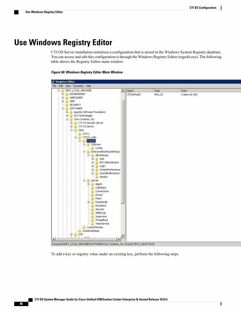
Use Windows Registry EditorCTI OS Server installation initializes a configuration that is stored in the Windows System Registry database.You can access and edit this configuration is through theWindows Registry Editor (regedit.exe). The followingtable shows the Registry Editor main window.
Figure 50: Windows Registry Editor Main Window
To add a key or registry value under an existing key, perform the following steps.
CTI OS System Manager Guide for Cisco Unified ICM/Contact Center Enterprise & Hosted Release 10.5(1)86
CTI OS ConfigurationUse Windows Registry Editor
Procedure
Step 1 Highlight the existing key in the left panel.Step 2 Position the cursor in the right panel and click.
A popup menu appears.
Step 3 From the popup menu, select Key, String Value, Binary Value, or DWORD value.If you select Key, a placeholder for the key you want to add appears highlighted in the left panel. For otheritems, a placeholder for the item you want to add appears highlighted in the right panel.
Step 4 Right-click the highlighted item. A popup menu appears.
• To name the item, select Rename from the popup menu; then type the new name for the item.
• To set the value data for String, Binary, and DWORD values, selectModify. A dialog box appears.Enter the value data following the Value Data prompt.
To edit an existing key or registry value, highlight the key or value and right-click it. SelectModify, Delete,or Rename from the popup menu and proceed.
After you make a change to the registry, you must restart the CTI OS processes before the new settingcan take effect.
Note
Silent Monitor Type Configuration for CTI OSYou can configure the CTI OS can be configured to use either the Unified CM-based silent monitor or theCTI OS-based silent monitor. You accomplish this by setting the following field in the CTI OS registry:
HKEY_LOCAL_MACHINE\SOFTWARE\Cisco Systems Inc.\CTIOS\<CTIOSInstanceName>\<CTIOSServerName>\EnterpriseDesktopSettings\AllDesktops\IPCCSilentMonitor\Name\Settings\CCMBasedSilentMonitor
This field is a DWORD and if present and set to “1”, Unified CM-based silent monitor is used.
CTI OS-based silent monitor is used if this field is not present or if it is present and set to “0”.
You can also run the setup program to reconfigure the CTI OS-based silent monitor.
If the server setup program is not run, the CCMBasedSilentMonitor field is not present. As a result, CTIOS-based silent monitor is used.
Note
CTI OS System Manager Guide for Cisco Unified ICM/Contact Center Enterprise & Hosted Release 10.5(1) 87
CTI OS ConfigurationSilent Monitor Type Configuration for CTI OS
Virtual Desktop InfrastructureVirtual Desktop Infrastructure (VDI) is a server-centric computing model. It is designed to help you to hostand centrally manage desktop virtual machines in the data center, while providing a full PC desktop experience.
The VMware View portfolio of products VDI lets IT run virtual desktops in the data center while giving youa single view of all your applications and data in a familiar, personalized environment on any device at anylocation. VDI provides greater flexibility, reliability, efficiency, and securitymanaging desktops and applicationsfrom the datacenter.
CTI OS Desktop Installations on VDI Agent Desktops
PrerequisitesComplete functional VDI deployment as per the VDI requirements. For more information, see http://www.vmware.com/products/view/.
Install CTI OS Desktop on VDI Agent
Procedure
Step 1 On any VDI agent desktop, run the CTI OS client installer and configure the desktop. For more informationon the deployment, limitations, and supported features of CTI OS desktops on VDI, see CTI OS SystemManager's Guide for Cisco Unified ICM/Contact Center Enterprise & Hosted .
Step 2 When the installation is complete, launch the CTI OS desktop and verify basic functionality by logging in anagent, changing agent states, or making calls.
Step 3 After you complete the testing, follow the same steps on the other VDI agent desktops.
Notes and Restrictions
Silent Monitoring
CTI OS-based silent monitoring is not supported due to physical limitations. For CTI OS-based silentmonitoring, youmust connect the agent machine to the network via the phone hard-set. This cannot be achievedwith a Virtual Machine, such as when using VDI.
ThinApp
For more information about ThinApp, see http://www.vmware.com/products/thinapp.
CTI OS System Manager Guide for Cisco Unified ICM/Contact Center Enterprise & Hosted Release 10.5(1)88
CTI OS ConfigurationVirtual Desktop Infrastructure

CTI Driver KeyThe CTI Driver key includes registry settings required for CTI Server connection. The CTI Driver key containsone key, the Config key. The following table describes the CtiDriver/Config key registry values.
Table 6: Registry Values for [CtiDriver\Config]
DefaultDescriptionValue TypeRegistry Value Name
CTIOSServerThe identifier of the CTI Client. This appearsin the CTI Server log file to help identify whichsession the CTI OS Server is connected on.
String ValueClientID
CTIOSServerThe password of the CTI Client. This appearsin the CTI Server log file to help identify whichsession the CTI OS Server is connected on.
String ValueClientPassword
CTIOSServerThe signature of the CTI Client. This appearsin the CTI Server log file to help identify whichsession the CTI OS Server is connected on.
String ValueClientSignature
Host specifiedduring CTIServerinstallation.
The CTI Server (sideA) IP address or hostnameto which the CTI OS Server connects.
String ValueSideAHost
Port specifiedduring CTIServerinstallation.
The CTI Server (sideA) IP port to which theCTI OS Server connects.
DWORD ValueSideAPort
Host specifiedduring CTIServerinstallation.
The CTI Server (sideB) IP address or hostnameto which the CTI OS Server connects.
String ValueSideBHost
Port specifiedduring CTIServerinstallation.
The CTI Server (sideB) IP port to which theCTI OS Server connects.
DWORD ValueSideBPort
5The interval (in seconds) at whichHEARTBEAT_REQ messages are sent to theCTI Server.
DWORD ValueHeartbeat Interval
CTI OS System Manager Guide for Cisco Unified ICM/Contact Center Enterprise & Hosted Release 10.5(1) 89
CTI OS ConfigurationCTI Driver Key
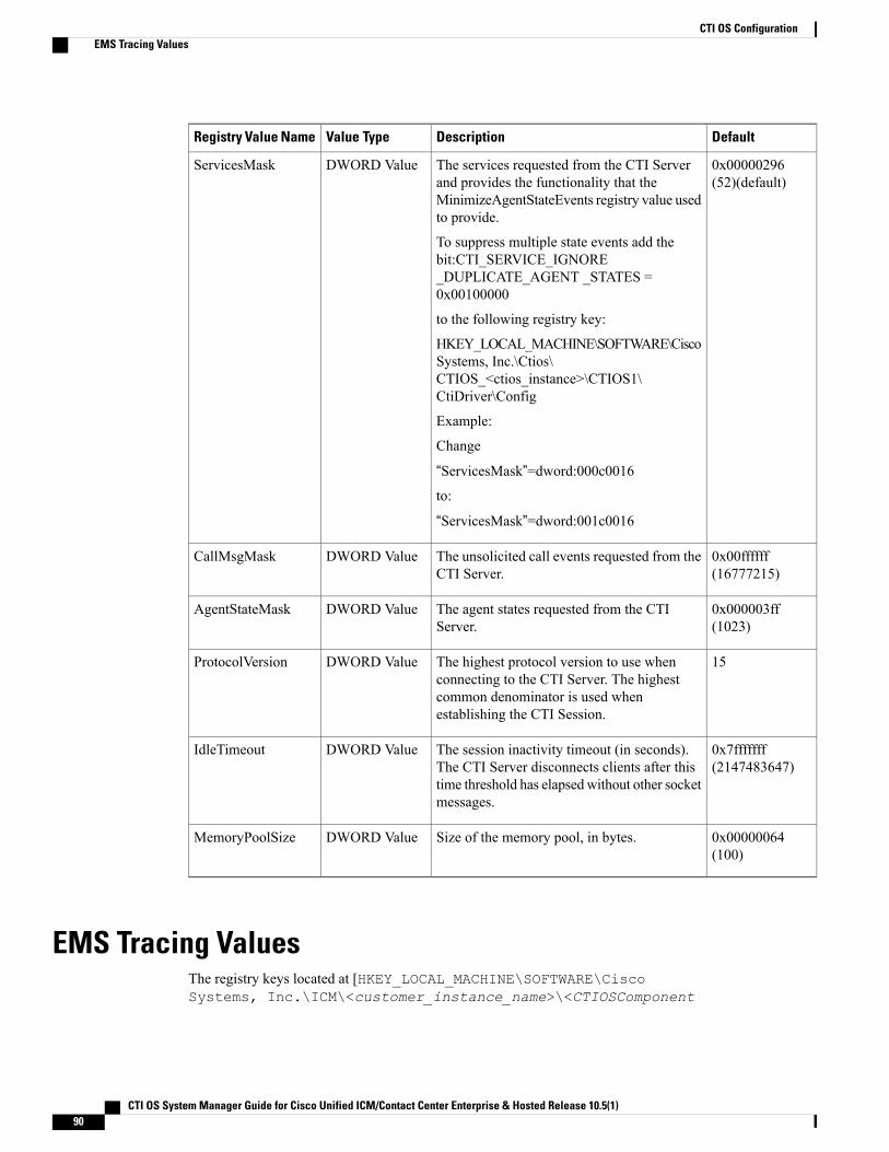
DefaultDescriptionValue TypeRegistry Value Name
0x00000296(52)(default)
The services requested from the CTI Serverand provides the functionality that theMinimizeAgentStateEvents registry value usedto provide.
To suppress multiple state events add thebit:CTI_SERVICE_IGNORE_DUPLICATE_AGENT _STATES =0x00100000
to the following registry key:
HKEY_LOCAL_MACHINE\SOFTWARE\CiscoSystems, Inc.\Ctios\CTIOS_<ctios_instance>\CTIOS1\CtiDriver\Config
Example:
Change
“ServicesMask”=dword:000c0016to:
“ServicesMask”=dword:001c0016
DWORD ValueServicesMask
0x00ffffff(16777215)
The unsolicited call events requested from theCTI Server.
DWORD ValueCallMsgMask
0x000003ff(1023)
The agent states requested from the CTIServer.
DWORD ValueAgentStateMask
15The highest protocol version to use whenconnecting to the CTI Server. The highestcommon denominator is used whenestablishing the CTI Session.
DWORD ValueProtocolVersion
0x7fffffff(2147483647)
The session inactivity timeout (in seconds).The CTI Server disconnects clients after thistime threshold has elapsedwithout other socketmessages.
DWORD ValueIdleTimeout
0x00000064(100)
Size of the memory pool, in bytes.DWORD ValueMemoryPoolSize
EMS Tracing ValuesThe registry keys located at [HKEY_LOCAL_MACHINE\SOFTWARE\CiscoSystems, Inc.\ICM\<customer_instance_name>\<CTIOSComponent
CTI OS System Manager Guide for Cisco Unified ICM/Contact Center Enterprise & Hosted Release 10.5(1)90
CTI OS ConfigurationEMS Tracing Values
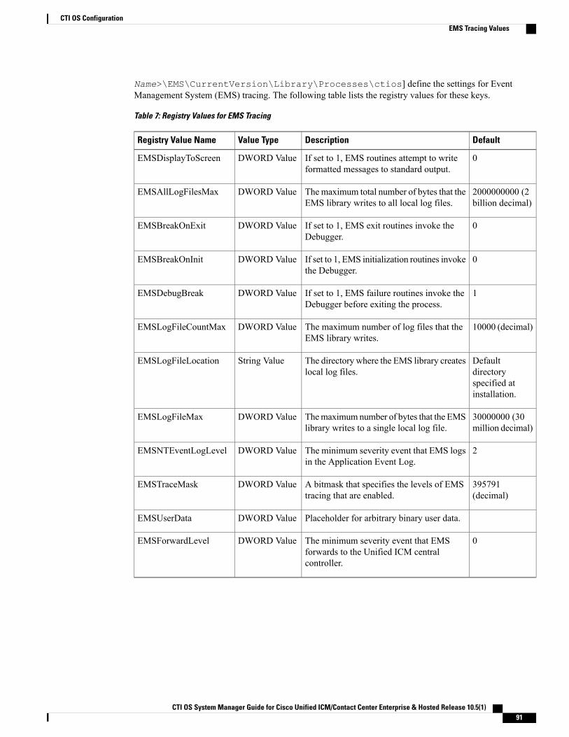
Name>\EMS\CurrentVersion\Library\Processes\ctios] define the settings for EventManagement System (EMS) tracing. The following table lists the registry values for these keys.
Table 7: Registry Values for EMS Tracing
DefaultDescriptionValue TypeRegistry Value Name
0If set to 1, EMS routines attempt to writeformatted messages to standard output.
DWORD ValueEMSDisplayToScreen
2000000000 (2billion decimal)
Themaximum total number of bytes that theEMS library writes to all local log files.
DWORD ValueEMSAllLogFilesMax
0If set to 1, EMS exit routines invoke theDebugger.
DWORD ValueEMSBreakOnExit
0If set to 1, EMS initialization routines invokethe Debugger.
DWORD ValueEMSBreakOnInit
1If set to 1, EMS failure routines invoke theDebugger before exiting the process.
DWORD ValueEMSDebugBreak
10000 (decimal)The maximum number of log files that theEMS library writes.
DWORD ValueEMSLogFileCountMax
Defaultdirectoryspecified atinstallation.
The directory where the EMS library createslocal log files.
String ValueEMSLogFileLocation
30000000 (30million decimal)
Themaximumnumber of bytes that the EMSlibrary writes to a single local log file.
DWORD ValueEMSLogFileMax
2The minimum severity event that EMS logsin the Application Event Log.
DWORD ValueEMSNTEventLogLevel
395791(decimal)
A bitmask that specifies the levels of EMStracing that are enabled.
DWORD ValueEMSTraceMask
Placeholder for arbitrary binary user data.DWORD ValueEMSUserData
0The minimum severity event that EMSforwards to the Unified ICM centralcontroller.
DWORD ValueEMSForwardLevel
CTI OS System Manager Guide for Cisco Unified ICM/Contact Center Enterprise & Hosted Release 10.5(1) 91
CTI OS ConfigurationEMS Tracing Values
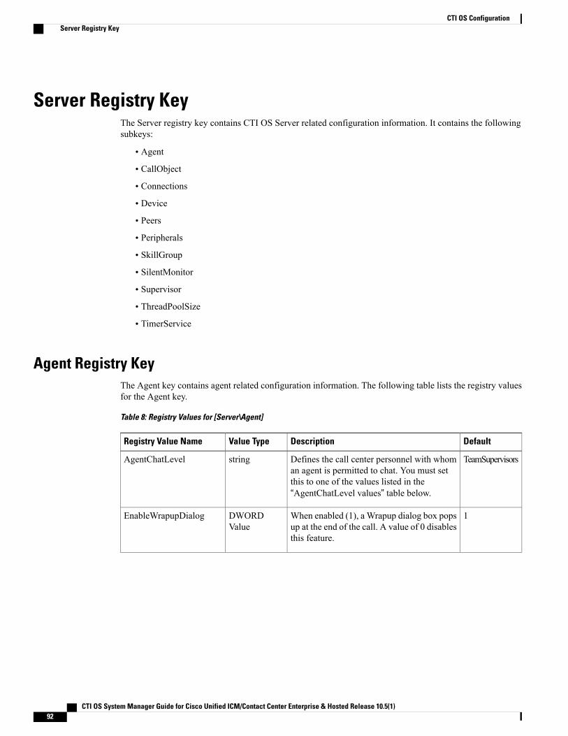
Server Registry KeyThe Server registry key contains CTI OS Server related configuration information. It contains the followingsubkeys:
• Agent
• CallObject
• Connections
• Device
• Peers
• Peripherals
• SkillGroup
• SilentMonitor
• Supervisor
• ThreadPoolSize
• TimerService
Agent Registry KeyThe Agent key contains agent related configuration information. The following table lists the registry valuesfor the Agent key.
Table 8: Registry Values for [Server\Agent]
DefaultDescriptionValue TypeRegistry Value Name
TeamSupervisorsDefines the call center personnel with whoman agent is permitted to chat. You must setthis to one of the values listed in the“AgentChatLevel values” table below.
stringAgentChatLevel
1When enabled (1), a Wrapup dialog box popsup at the end of the call. A value of 0 disablesthis feature.
DWORDValue
EnableWrapupDialog
CTI OS System Manager Guide for Cisco Unified ICM/Contact Center Enterprise & Hosted Release 10.5(1)92
CTI OS ConfigurationServer Registry Key
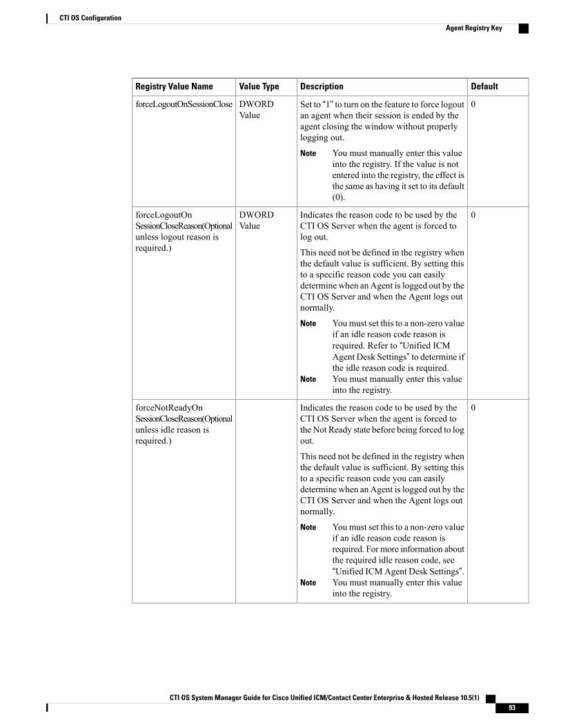
DefaultDescriptionValue TypeRegistry Value Name
0Set to “1” to turn on the feature to force logoutan agent when their session is ended by theagent closing the window without properlylogging out.
You must manually enter this valueinto the registry. If the value is notentered into the registry, the effect isthe same as having it set to its default(0).
Note
DWORDValue
forceLogoutOnSessionClose
0Indicates the reason code to be used by theCTI OS Server when the agent is forced tolog out.
This need not be defined in the registry whenthe default value is sufficient. By setting thisto a specific reason code you can easilydetermine when anAgent is logged out by theCTI OS Server and when the Agent logs outnormally.
Youmust set this to a non-zero valueif an idle reason code reason isrequired. Refer to “Unified ICMAgent Desk Settings” to determine ifthe idle reason code is required.
Note
You must manually enter this valueinto the registry.
Note
DWORDValue
forceLogoutOnSessionCloseReason(Optionalunless logout reason isrequired.)
0Indicates the reason code to be used by theCTI OS Server when the agent is forced tothe Not Ready state before being forced to logout.
This need not be defined in the registry whenthe default value is sufficient. By setting thisto a specific reason code you can easilydetermine when anAgent is logged out by theCTI OS Server and when the Agent logs outnormally.
Youmust set this to a non-zero valueif an idle reason code reason isrequired. Formore information aboutthe required idle reason code, see“Unified ICMAgent Desk Settings”.
Note
You must manually enter this valueinto the registry.
Note
forceNotReadyOnSessionCloseReason(Optionalunless idle reason isrequired.)
CTI OS System Manager Guide for Cisco Unified ICM/Contact Center Enterprise & Hosted Release 10.5(1) 93
CTI OS ConfigurationAgent Registry Key
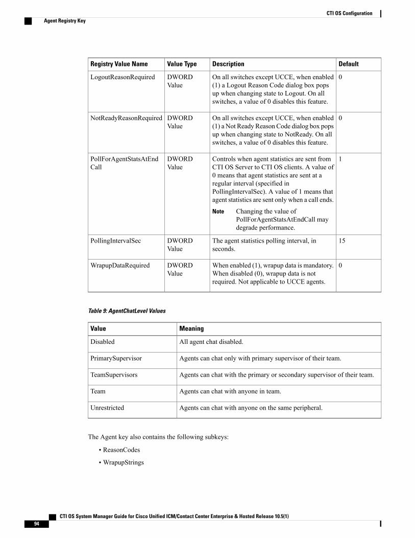
DefaultDescriptionValue TypeRegistry Value Name
0On all switches except UCCE, when enabled(1) a Logout Reason Code dialog box popsup when changing state to Logout. On allswitches, a value of 0 disables this feature.
DWORDValue
LogoutReasonRequired
0On all switches except UCCE, when enabled(1) a Not Ready Reason Code dialog box popsup when changing state to NotReady. On allswitches, a value of 0 disables this feature.
DWORDValue
NotReadyReasonRequired
1Controls when agent statistics are sent fromCTI OS Server to CTI OS clients. A value of0 means that agent statistics are sent at aregular interval (specified inPollingIntervalSec). A value of 1 means thatagent statistics are sent only when a call ends.
Changing the value ofPollForAgentStatsAtEndCall maydegrade performance.
Note
DWORDValue
PollForAgentStatsAtEndCall
15The agent statistics polling interval, inseconds.
DWORDValue
PollingIntervalSec
0When enabled (1), wrapup data is mandatory.When disabled (0), wrapup data is notrequired. Not applicable to UCCE agents.
DWORDValue
WrapupDataRequired
Table 9: AgentChatLevel Values
MeaningValue
All agent chat disabled.Disabled
Agents can chat only with primary supervisor of their team.PrimarySupervisor
Agents can chat with the primary or secondary supervisor of their team.TeamSupervisors
Agents can chat with anyone in team.Team
Agents can chat with anyone on the same peripheral.Unrestricted
The Agent key also contains the following subkeys:
• ReasonCodes
•WrapupStrings
CTI OS System Manager Guide for Cisco Unified ICM/Contact Center Enterprise & Hosted Release 10.5(1)94
CTI OS ConfigurationAgent Registry Key
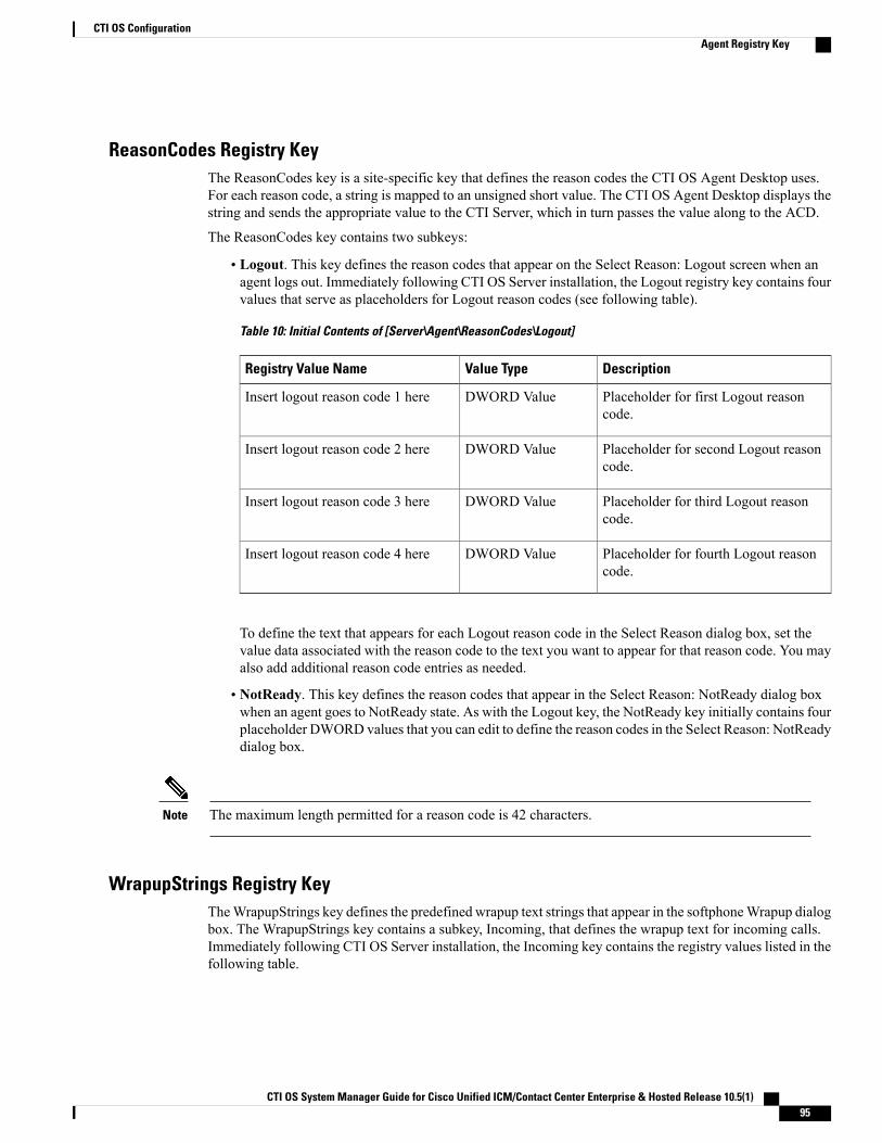
ReasonCodes Registry KeyThe ReasonCodes key is a site-specific key that defines the reason codes the CTI OS Agent Desktop uses.For each reason code, a string is mapped to an unsigned short value. The CTI OS Agent Desktop displays thestring and sends the appropriate value to the CTI Server, which in turn passes the value along to the ACD.
The ReasonCodes key contains two subkeys:
• Logout. This key defines the reason codes that appear on the Select Reason: Logout screen when anagent logs out. Immediately following CTI OS Server installation, the Logout registry key contains fourvalues that serve as placeholders for Logout reason codes (see following table).
Table 10: Initial Contents of [Server\Agent\ReasonCodes\Logout]
DescriptionValue TypeRegistry Value Name
Placeholder for first Logout reasoncode.
DWORD ValueInsert logout reason code 1 here
Placeholder for second Logout reasoncode.
DWORD ValueInsert logout reason code 2 here
Placeholder for third Logout reasoncode.
DWORD ValueInsert logout reason code 3 here
Placeholder for fourth Logout reasoncode.
DWORD ValueInsert logout reason code 4 here
To define the text that appears for each Logout reason code in the Select Reason dialog box, set thevalue data associated with the reason code to the text you want to appear for that reason code. You mayalso add additional reason code entries as needed.
• NotReady. This key defines the reason codes that appear in the Select Reason: NotReady dialog boxwhen an agent goes to NotReady state. As with the Logout key, the NotReady key initially contains fourplaceholder DWORD values that you can edit to define the reason codes in the Select Reason: NotReadydialog box.
The maximum length permitted for a reason code is 42 characters.Note
WrapupStrings Registry KeyTheWrapupStrings key defines the predefined wrapup text strings that appear in the softphoneWrapup dialogbox. The WrapupStrings key contains a subkey, Incoming, that defines the wrapup text for incoming calls.Immediately following CTI OS Server installation, the Incoming key contains the registry values listed in thefollowing table.
CTI OS System Manager Guide for Cisco Unified ICM/Contact Center Enterprise & Hosted Release 10.5(1) 95
CTI OS ConfigurationAgent Registry Key
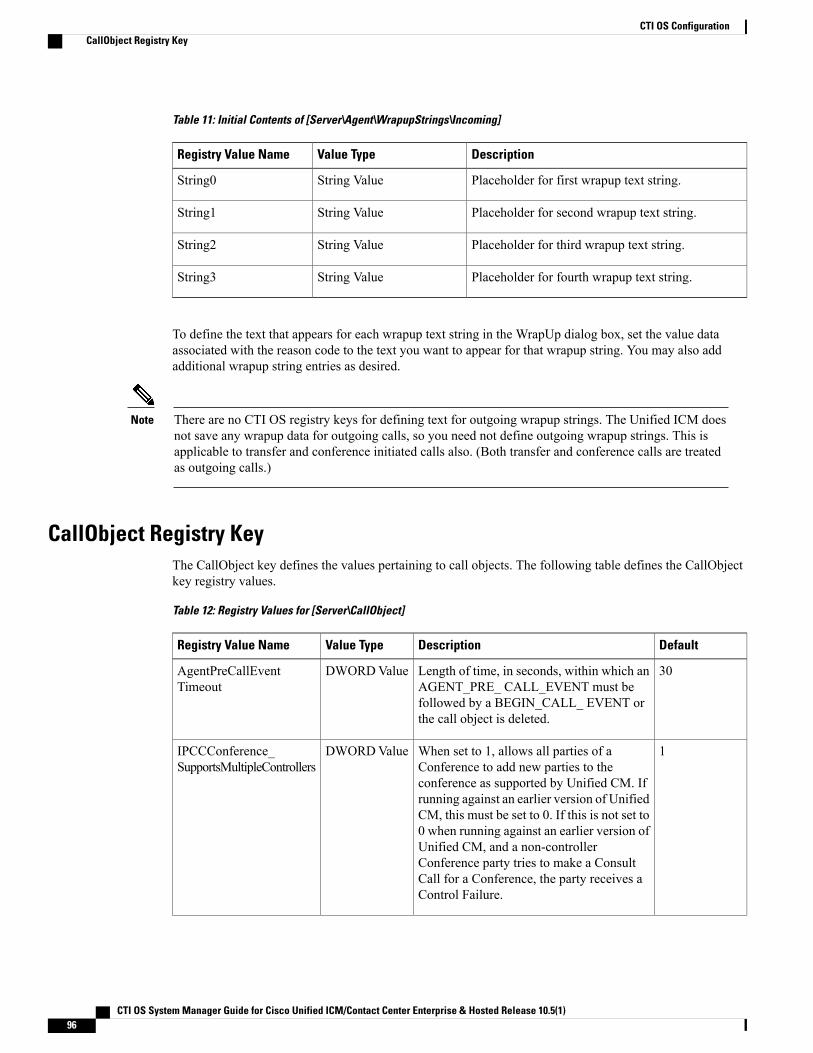
Table 11: Initial Contents of [Server\Agent\WrapupStrings\Incoming]
DescriptionValue TypeRegistry Value Name
Placeholder for first wrapup text string.String ValueString0
Placeholder for second wrapup text string.String ValueString1
Placeholder for third wrapup text string.String ValueString2
Placeholder for fourth wrapup text string.String ValueString3
To define the text that appears for each wrapup text string in the WrapUp dialog box, set the value dataassociated with the reason code to the text you want to appear for that wrapup string. You may also addadditional wrapup string entries as desired.
There are no CTI OS registry keys for defining text for outgoing wrapup strings. The Unified ICM doesnot save any wrapup data for outgoing calls, so you need not define outgoing wrapup strings. This isapplicable to transfer and conference initiated calls also. (Both transfer and conference calls are treatedas outgoing calls.)
Note
CallObject Registry KeyThe CallObject key defines the values pertaining to call objects. The following table defines the CallObjectkey registry values.
Table 12: Registry Values for [Server\CallObject]
DefaultDescriptionValue TypeRegistry Value Name
30Length of time, in seconds, within which anAGENT_PRE_ CALL_EVENT must befollowed by a BEGIN_CALL_ EVENT orthe call object is deleted.
DWORDValueAgentPreCallEventTimeout
1When set to 1, allows all parties of aConference to add new parties to theconference as supported by Unified CM. Ifrunning against an earlier version of UnifiedCM, this must be set to 0. If this is not set to0 when running against an earlier version ofUnified CM, and a non-controllerConference party tries to make a ConsultCall for a Conference, the party receives aControl Failure.
DWORDValueIPCCConference_SupportsMultipleControllers
CTI OS System Manager Guide for Cisco Unified ICM/Contact Center Enterprise & Hosted Release 10.5(1)96
CTI OS ConfigurationCallObject Registry Key
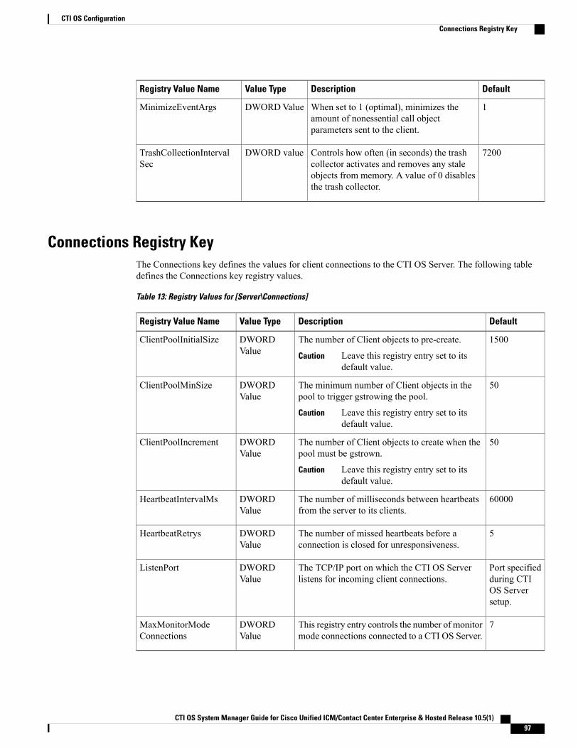
DefaultDescriptionValue TypeRegistry Value Name
1When set to 1 (optimal), minimizes theamount of nonessential call objectparameters sent to the client.
DWORDValueMinimizeEventArgs
7200Controls how often (in seconds) the trashcollector activates and removes any staleobjects from memory. A value of 0 disablesthe trash collector.
DWORD valueTrashCollectionIntervalSec
Connections Registry KeyThe Connections key defines the values for client connections to the CTI OS Server. The following tabledefines the Connections key registry values.
Table 13: Registry Values for [Server\Connections]
DefaultDescriptionValue TypeRegistry Value Name
1500The number of Client objects to pre-create.
Leave this registry entry set to itsdefault value.
Caution
DWORDValue
ClientPoolInitialSize
50The minimum number of Client objects in thepool to trigger gstrowing the pool.
Leave this registry entry set to itsdefault value.
Caution
DWORDValue
ClientPoolMinSize
50The number of Client objects to create when thepool must be gstrown.
Leave this registry entry set to itsdefault value.
Caution
DWORDValue
ClientPoolIncrement
60000The number of milliseconds between heartbeatsfrom the server to its clients.
DWORDValue
HeartbeatIntervalMs
5The number of missed heartbeats before aconnection is closed for unresponsiveness.
DWORDValue
HeartbeatRetrys
Port specifiedduring CTIOS Serversetup.
The TCP/IP port on which the CTI OS Serverlistens for incoming client connections.
DWORDValue
ListenPort
7This registry entry controls the number of monitormode connections connected to a CTI OS Server.
DWORDValue
MaxMonitorModeConnections
CTI OS System Manager Guide for Cisco Unified ICM/Contact Center Enterprise & Hosted Release 10.5(1) 97
CTI OS ConfigurationConnections Registry Key
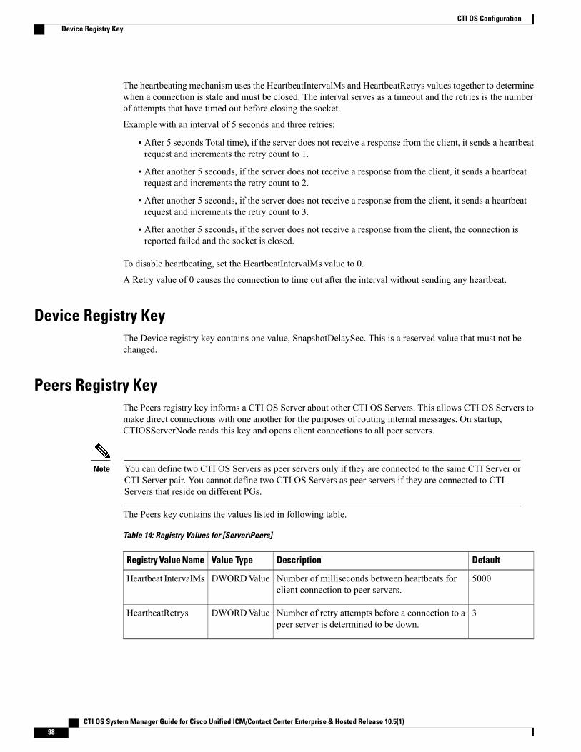
The heartbeating mechanism uses the HeartbeatIntervalMs and HeartbeatRetrys values together to determinewhen a connection is stale and must be closed. The interval serves as a timeout and the retries is the numberof attempts that have timed out before closing the socket.
Example with an interval of 5 seconds and three retries:
• After 5 seconds Total time), if the server does not receive a response from the client, it sends a heartbeatrequest and increments the retry count to 1.
• After another 5 seconds, if the server does not receive a response from the client, it sends a heartbeatrequest and increments the retry count to 2.
• After another 5 seconds, if the server does not receive a response from the client, it sends a heartbeatrequest and increments the retry count to 3.
• After another 5 seconds, if the server does not receive a response from the client, the connection isreported failed and the socket is closed.
To disable heartbeating, set the HeartbeatIntervalMs value to 0.
A Retry value of 0 causes the connection to time out after the interval without sending any heartbeat.
Device Registry KeyThe Device registry key contains one value, SnapshotDelaySec. This is a reserved value that must not bechanged.
Peers Registry KeyThe Peers registry key informs a CTI OS Server about other CTI OS Servers. This allows CTI OS Servers tomake direct connections with one another for the purposes of routing internal messages. On startup,CTIOSServerNode reads this key and opens client connections to all peer servers.
You can define two CTI OS Servers as peer servers only if they are connected to the same CTI Server orCTI Server pair. You cannot define two CTI OS Servers as peer servers if they are connected to CTIServers that reside on different PGs.
Note
The Peers key contains the values listed in following table.
Table 14: Registry Values for [Server\Peers]
DefaultDescriptionValue TypeRegistry Value Name
5000Number of milliseconds between heartbeats forclient connection to peer servers.
DWORDValueHeartbeat IntervalMs
3Number of retry attempts before a connection to apeer server is determined to be down.
DWORDValueHeartbeatRetrys
CTI OS System Manager Guide for Cisco Unified ICM/Contact Center Enterprise & Hosted Release 10.5(1)98
CTI OS ConfigurationDevice Registry Key
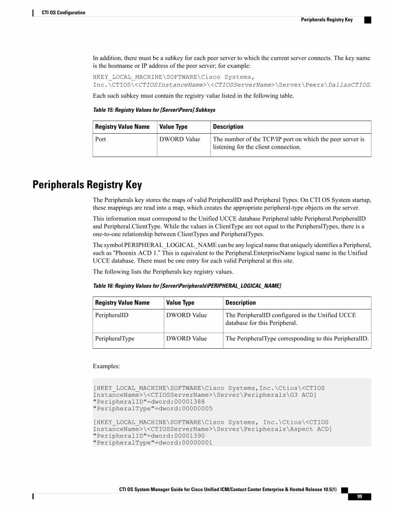
In addition, there must be a subkey for each peer server to which the current server connects. The key nameis the hostname or IP address of the peer server; for example:
HKEY_LOCAL_MACHINE\SOFTWARE\Cisco Systems,Inc.\CTIOS\<CTIOSInstanceName>\<CTIOSServerName>\Server\Peers\DallasCTIOS.
Each such subkey must contain the registry value listed in the following table.
Table 15: Registry Values for [Server\Peers] Subkeys
DescriptionValue TypeRegistry Value Name
The number of the TCP/IP port on which the peer server islistening for the client connection.
DWORD ValuePort
Peripherals Registry KeyThe Peripherals key stores the maps of valid PeripheralID and Peripheral Types. On CTI OS System startup,these mappings are read into a map, which creates the appropriate peripheral-type objects on the server.
This information must correspond to the Unified UCCE database Peripheral table Peripheral.PeripheralIDand Peripheral.ClientType. While the values in ClientType are not equal to the PeripheralTypes, there is aone-to-one relationship between ClientTypes and PeripheralTypes.
The symbol PERIPHERAL_LOGICAL_NAMEcan be any logical name that uniquely identifies a Peripheral,such as “Phoenix ACD 1.” This is equivalent to the Peripheral.EnterpriseName logical name in the UnifiedUCCE database. There must be one entry for each valid Peripheral at this site.
The following lists the Peripherals key registry values.
Table 16: Registry Values for [Server\Peripherals\PERIPHERAL_LOGICAL_NAME]
DescriptionValue TypeRegistry Value Name
The PeripheralID configured in the Unified UCCEdatabase for this Peripheral.
DWORD ValuePeripheralID
The PeripheralType corresponding to this PeripheralID.DWORD ValuePeripheralType
Examples:
[HKEY_LOCAL_MACHINE\SOFTWARE\Cisco Systems,Inc.\Ctios\<CTIOSInstanceName>\<CTIOSServerName>\Server\Peripherals\G3 ACD]"PeripheralID"=dword:00001388"PeripheralType"=dword:00000005
[HKEY_LOCAL_MACHINE\SOFTWARE\Cisco Systems, Inc.\Ctios\<CTIOSInstanceName>\<CTIOSServerName>\Server\Peripherals\Aspect ACD]"PeripheralID"=dword:00001390"PeripheralType"=dword:00000001
CTI OS System Manager Guide for Cisco Unified ICM/Contact Center Enterprise & Hosted Release 10.5(1) 99
CTI OS ConfigurationPeripherals Registry Key
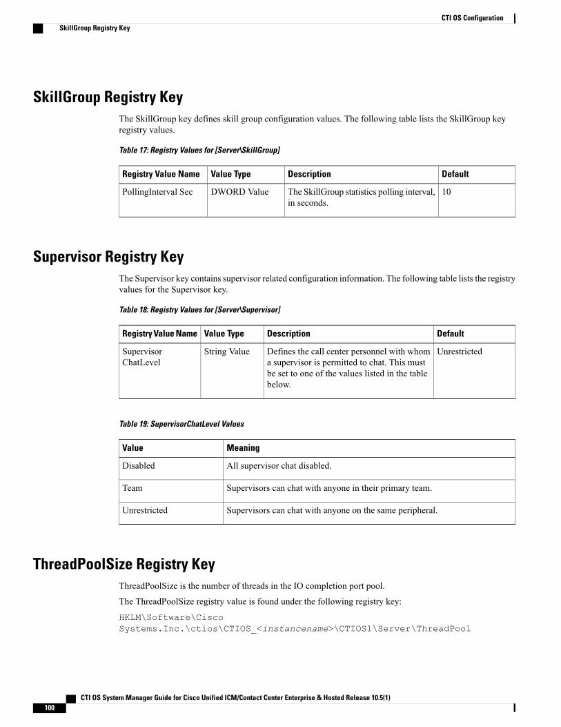
SkillGroup Registry KeyThe SkillGroup key defines skill group configuration values. The following table lists the SkillGroup keyregistry values.
Table 17: Registry Values for [Server\SkillGroup]
DefaultDescriptionValue TypeRegistry Value Name
10The SkillGroup statistics polling interval,in seconds.
DWORD ValuePollingInterval Sec
Supervisor Registry KeyThe Supervisor key contains supervisor related configuration information. The following table lists the registryvalues for the Supervisor key.
Table 18: Registry Values for [Server\Supervisor]
DefaultDescriptionValue TypeRegistry Value Name
UnrestrictedDefines the call center personnel with whoma supervisor is permitted to chat. This mustbe set to one of the values listed in the tablebelow.
String ValueSupervisorChatLevel
Table 19: SupervisorChatLevel Values
MeaningValue
All supervisor chat disabled.Disabled
Supervisors can chat with anyone in their primary team.Team
Supervisors can chat with anyone on the same peripheral.Unrestricted
ThreadPoolSize Registry KeyThreadPoolSize is the number of threads in the IO completion port pool.
The ThreadPoolSize registry value is found under the following registry key:
HKLM\Software\CiscoSystems.Inc.\ctios\CTIOS_<instancename>\CTIOS1\Server\ThreadPool
CTI OS System Manager Guide for Cisco Unified ICM/Contact Center Enterprise & Hosted Release 10.5(1)100
CTI OS ConfigurationSkillGroup Registry Key
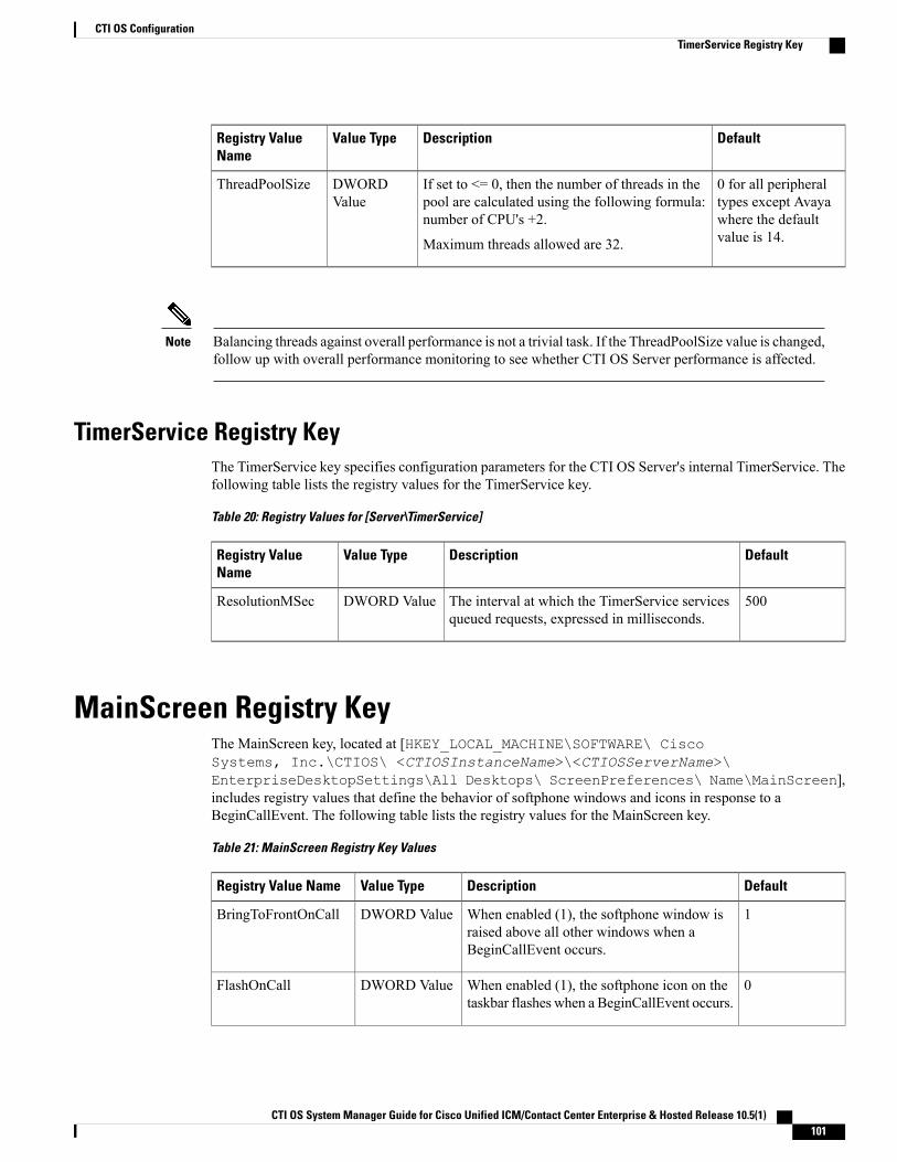
DefaultDescriptionValue TypeRegistry ValueName
0 for all peripheraltypes except Avayawhere the defaultvalue is 14.
If set to <= 0, then the number of threads in thepool are calculated using the following formula:number of CPU's +2.
Maximum threads allowed are 32.
DWORDValue
ThreadPoolSize
Balancing threads against overall performance is not a trivial task. If the ThreadPoolSize value is changed,follow up with overall performance monitoring to see whether CTI OS Server performance is affected.
Note
TimerService Registry KeyThe TimerService key specifies configuration parameters for the CTI OS Server's internal TimerService. Thefollowing table lists the registry values for the TimerService key.
Table 20: Registry Values for [Server\TimerService]
DefaultDescriptionValue TypeRegistry ValueName
500The interval at which the TimerService servicesqueued requests, expressed in milliseconds.
DWORD ValueResolutionMSec
MainScreen Registry KeyThe MainScreen key, located at [HKEY_LOCAL_MACHINE\SOFTWARE\ CiscoSystems, Inc.\CTIOS\ <CTIOSInstanceName>\<CTIOSServerName>\EnterpriseDesktopSettings\All Desktops\ ScreenPreferences\ Name\MainScreen],includes registry values that define the behavior of softphone windows and icons in response to aBeginCallEvent. The following table lists the registry values for the MainScreen key.
Table 21: MainScreen Registry Key Values
DefaultDescriptionValue TypeRegistry Value Name
1When enabled (1), the softphone window israised above all other windows when aBeginCallEvent occurs.
DWORD ValueBringToFrontOnCall
0When enabled (1), the softphone icon on thetaskbar flashes when a BeginCallEvent occurs.
DWORD ValueFlashOnCall
CTI OS System Manager Guide for Cisco Unified ICM/Contact Center Enterprise & Hosted Release 10.5(1) 101
CTI OS ConfigurationTimerService Registry Key
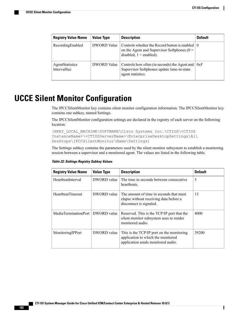
DefaultDescriptionValue TypeRegistry Value Name
0Controls whether the Record button is enabledon the Agent and Supervisor Softphones (0 =disabled, 1 = enabled).
DWORD ValueRecordingEnabled
0xFControls how often (in seconds) the Agent andSupervisor Softphones update time-in-stateagent statistics.
DWORD ValueAgentStatisticsIntervalSec
UCCE Silent Monitor ConfigurationThe IPCCSilentMonitor key contains silent monitor configuration information. The IPCCSilentMonitor keycontains one subkey, named Settings.
The IPCCSilentMonitor configuration settings are declared in the registry of each server on the followinglocation:
[HKEY_LOCAL_MACHINE\SOFTWARE\Cisco Systems Inc.\CTIOS\<CTIOSInstanceName>\<CTIOSServerName>\EnterpriseDesktopSettings\AllDesktops\IPCCSilentMonitor\Name\Settings]
The Settings subkey contains the parameters used by the silent monitor subsystem to establish a monitoringsession between a supervisor and a monitored agent. The values are listed in the following table.
Table 22: Settings Registry Subkey Values
DefaultDescriptionValue TypeRegistry Value Name
5The time in seconds between consecutiveheartbeats.
DWORD valueHeartbeatInterval
15The amount of time in seconds that mustelapse without receiving data before adisconnect is signaled.
DWORD valueHeartbeatTimeout
4000Reserved. This is the TCP/IP port that thesilent monitor subsystem uses to rendermonitored audio.
DWORD valueMediaTerminationPort
39200This is the TCP/IP port on the monitoringapplication to which the monitoredapplication sends monitored audio.
DWORD valueMonitoringIPPort
CTI OS System Manager Guide for Cisco Unified ICM/Contact Center Enterprise & Hosted Release 10.5(1)102
CTI OS ConfigurationUCCE Silent Monitor Configuration
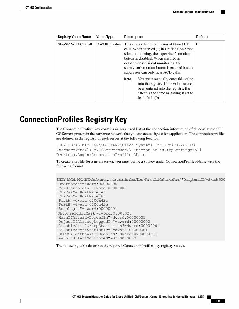
DefaultDescriptionValue TypeRegistry Value Name
0This stops silent monitoring of Non-ACDcalls.When enabled (1) in Unified CM-basedsilent monitoring, the supervisor's monitorbutton is disabled. When enabled indesktop-based silent monitoring, thesupervisor's monitor button is enabled but thesupervisor can only hear ACD calls.
You must manually enter this valueinto the registry. If the value has notbeen entered into the registry, theeffect is the same as having it set toits default (0).
Note
DWORD valueStopSMNonACDCall
ConnectionProfiles Registry KeyThe ConnectionProfiles key contains an organized list of the connection information of all configured CTIOS Servers present in the corporate network that you can access by a client application. The connection profilesare defined in the registry of each server at the following location:
HKEY_LOCAL_MACHINE\SOFTWARE\Cisco Systems Inc.\CtiOs\<CTIOSInstanceName>\<CTIOSServerName>\ EnterpriseDesktopSettings\AllDesktops\Login\ConnectionProfiles\Name
To create a profile for a given server, you must define a subkey under ConnectionProfiles\Name with thefollowing format:
[HKEY_LOCAL_MACHINE\Software\…\ConnectionProfiles\Name\CtiOsServerName]"PeripheralID"=dword:5000"Heartbeat"=dword:00000000"MaxHeartbeats"=dword:00000005"CtiOsA"="HostName_A""CtiOsB"="HostName_B""PortA"=dword:0000a42c"PortB"=dword:0000a42c"AutoLogin"=dword:00000001“ShowFieldBitMask”=dword:00000023"WarnIfAlreadyLoggedIn"=dword:00000001"RejectIfAlreadyLoggedIn"=dword:00000000"DisableSkillGroupStatistics"=dword:00000001"DisableAgentStatistics"=dword:00000001"UCCESilentMonitorEnabled"=dword:0x00000001"WarnIfSilentMonitored"=0x00000000
The following table describes the required ConnectionProfiles key registry values.
CTI OS System Manager Guide for Cisco Unified ICM/Contact Center Enterprise & Hosted Release 10.5(1) 103
CTI OS ConfigurationConnectionProfiles Registry Key
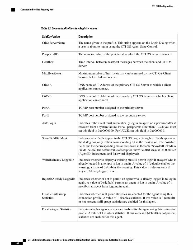
Table 23: ConnectionProfiles Key Registry Values
DescriptionSubKey/Value
The name given to the profile. This string appears on the Login Dialog whena user is about to log in using the CTI OS Agent State Control.
CtiOsServerName
The numeric value of the peripheral to which the CTI OS Server connects.PeripheralID
Time interval between heartbeat messages between the client and CTI OSServer.
Heartbeat
Maximum number of heartbeats that can be missed by the CTI OS ClientSession before failover occurs.
MaxHeartbeats
DNS name of IP Address of the primary CTI OS Server to which a clientapplication can connect.
CtiOsA
DNS name of IP Address of the secondary CTI OS Server to which a clientapplication can connect.
CtiOsB
TCP/IP port number assigned to the primary server.PortA
TCP/IP port number assigned to the secondary server.PortB
Indicates if the client must automatically log in an agent or supervisor after itrecovers from a system failure. For all peripherals other than UCCE you mustset this field to 0x00000000. For UCCE, set this field to 0x00000001.
AutoLogin
Indicates what fields appear in the CTI OS Login dialog box. Fields appear onthe dialog box only if their corresponding bit in the mask is on. The possiblefields and their correspondingmasks are shown in the table “ShowBitFieldMaskFields” below. The default value at setup for ShowFieldBitMask is 0x00000023(AgentID, Instrument, and Password displayed).
ShowFieldBit Mask
Indicates whether to display a warning but still permit login if an agent who isalready logged in attempts to log in again. A value of 1 (default) enables thewarning; a value of 0 disables the warning. This value is relevant only ifRejectIfAlreadyLoggedIn is 0.
WarnIfAlready LoggedIn
Indicates whether or not to permit an agent who is already logged in to log inagain. A value of 0 (default) permits an agent to log in again. A value of 1prohibits an agent from logging in again.
RejectIfAlready LoggedIn
Indicates whether skill group statistics are enabled for the agent using thisconnection profile. A value of 1 disables statistics. If this value is 0 (default)or not present, skill group statistics are enabled for this agent.
DisableSkillGroupStatistics
Indicates whether agent statistics are enabled for the agent using this connectionprofile. A value of 1 disables statistics. If this value is 0 (default) or not present,statistics are enabled for this agent.
DisableAgent Statistics
CTI OS System Manager Guide for Cisco Unified ICM/Contact Center Enterprise & Hosted Release 10.5(1)104
CTI OS ConfigurationConnectionProfiles Registry Key
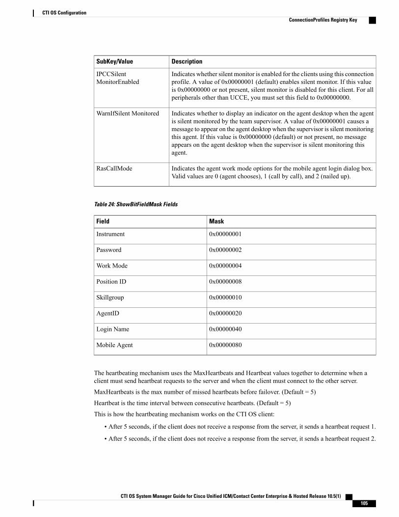
DescriptionSubKey/Value
Indicates whether silent monitor is enabled for the clients using this connectionprofile. A value of 0x00000001 (default) enables silent monitor. If this valueis 0x00000000 or not present, silent monitor is disabled for this client. For allperipherals other than UCCE, you must set this field to 0x00000000.
IPCCSilentMonitorEnabled
Indicates whether to display an indicator on the agent desktop when the agentis silent monitored by the team supervisor. A value of 0x00000001 causes amessage to appear on the agent desktop when the supervisor is silent monitoringthis agent. If this value is 0x00000000 (default) or not present, no messageappears on the agent desktop when the supervisor is silent monitoring thisagent.
WarnIfSilent Monitored
Indicates the agent work mode options for the mobile agent login dialog box.Valid values are 0 (agent chooses), 1 (call by call), and 2 (nailed up).
RasCallMode
Table 24: ShowBitFieldMask Fields
MaskField
0x00000001Instrument
0x00000002Password
0x00000004Work Mode
0x00000008Position ID
0x00000010Skillgroup
0x00000020AgentID
0x00000040Login Name
0x00000080Mobile Agent
The heartbeating mechanism uses the MaxHeartbeats and Heartbeat values together to determine when aclient must send heartbeat requests to the server and when the client must connect to the other server.
MaxHeartbeats is the max number of missed heartbeats before failover. (Default = 5)
Heartbeat is the time interval between consecutive heartbeats. (Default = 5)
This is how the heartbeating mechanism works on the CTI OS client:
• After 5 seconds, if the client does not receive a response from the server, it sends a heartbeat request 1.
• After 5 seconds, if the client does not receive a response from the server, it sends a heartbeat request 2.
CTI OS System Manager Guide for Cisco Unified ICM/Contact Center Enterprise & Hosted Release 10.5(1) 105
CTI OS ConfigurationConnectionProfiles Registry Key
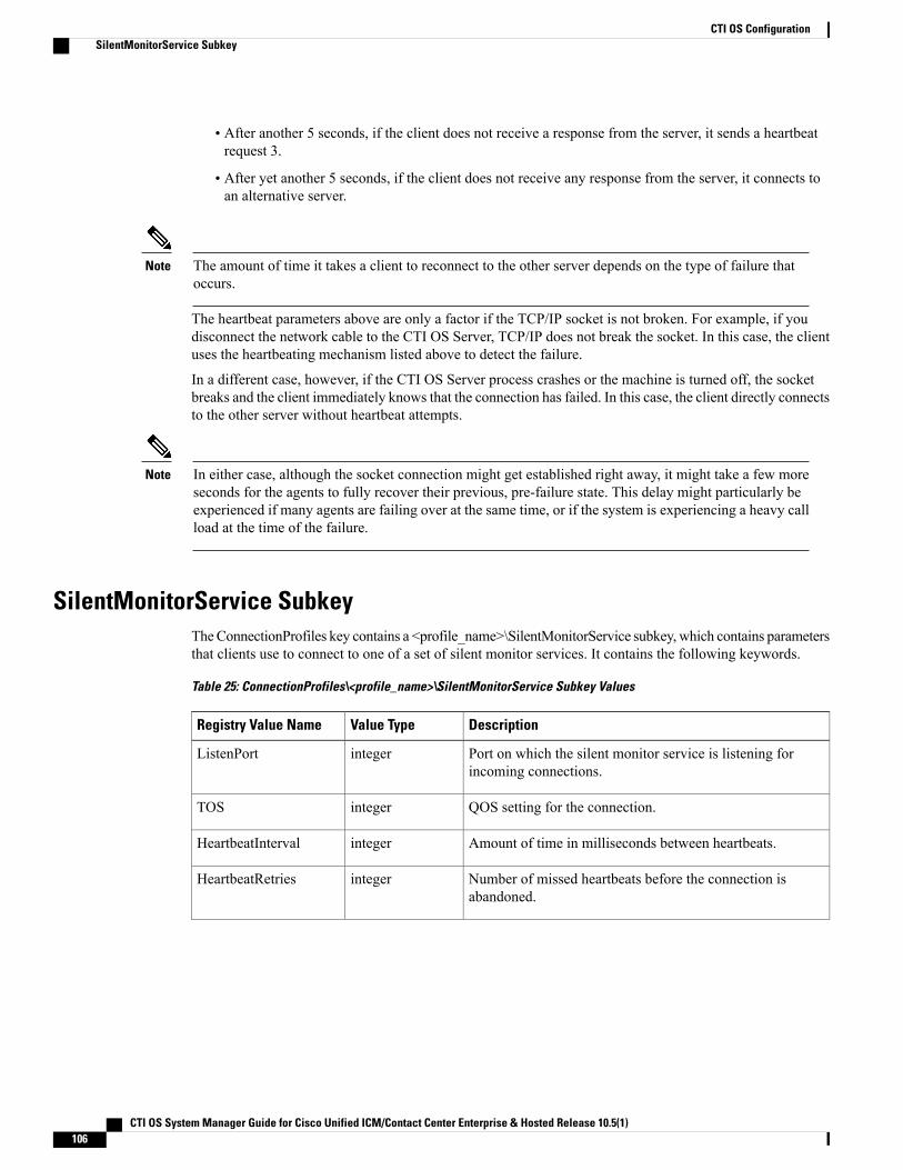
• After another 5 seconds, if the client does not receive a response from the server, it sends a heartbeatrequest 3.
• After yet another 5 seconds, if the client does not receive any response from the server, it connects toan alternative server.
The amount of time it takes a client to reconnect to the other server depends on the type of failure thatoccurs.
Note
The heartbeat parameters above are only a factor if the TCP/IP socket is not broken. For example, if youdisconnect the network cable to the CTI OS Server, TCP/IP does not break the socket. In this case, the clientuses the heartbeating mechanism listed above to detect the failure.
In a different case, however, if the CTI OS Server process crashes or the machine is turned off, the socketbreaks and the client immediately knows that the connection has failed. In this case, the client directly connectsto the other server without heartbeat attempts.
In either case, although the socket connection might get established right away, it might take a few moreseconds for the agents to fully recover their previous, pre-failure state. This delay might particularly beexperienced if many agents are failing over at the same time, or if the system is experiencing a heavy callload at the time of the failure.
Note
SilentMonitorService SubkeyTheConnectionProfiles key contains a <profile_name>\SilentMonitorService subkey, which contains parametersthat clients use to connect to one of a set of silent monitor services. It contains the following keywords.
Table 25: ConnectionProfiles\<profile_name>\SilentMonitorService Subkey Values
DescriptionValue TypeRegistry Value Name
Port on which the silent monitor service is listening forincoming connections.
integerListenPort
QOS setting for the connection.integerTOS
Amount of time in milliseconds between heartbeats.integerHeartbeatInterval
Number of missed heartbeats before the connection isabandoned.
integerHeartbeatRetries
CTI OS System Manager Guide for Cisco Unified ICM/Contact Center Enterprise & Hosted Release 10.5(1)106
CTI OS ConfigurationSilentMonitorService Subkey
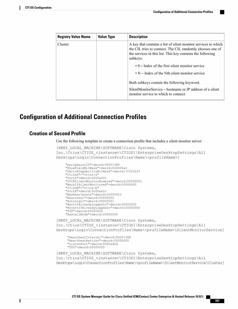
DescriptionValue TypeRegistry Value Name
A key that contains a list of silent monitor services to whichthe CIL tries to connect. The CIL randomly chooses one ofthe services in this list. This key contains the followingsubkeys:
• 0 – Index of the first silent monitor service
• N – Index of the Nth silent monitor service
Both subkeys contain the following keyword.
SilentMonitorService – hostname or IP address of a silentmonitor service to which to connect.
Cluster
Configuration of Additional Connection Profiles
Creation of Second ProfileUse the following template to create a connection profile that includes a silent monitor server:
[HKEY_LOCAL_MACHINE\SOFTWARE\Cisco Systems,Inc.\Ctios\CTIOS_<instance>\CTIOS1\EnterpriseDesktopSettings\AllDesktops\Login\ConnectionProfiles\Name\<profileName>]
"peripheralID"=dword:00001389"ShowFieldBitMask"=dword:000000a3"SwitchCapabilityBitMask"=dword:7f3f1bff"CtiOsA"="ctios-a""PortA"=dword:0000a42c"UCCESilentMonitorEnabled"=dword:00000001"WarnIfSilentMonitored"=dword:00000000"CtiOsB"="ctios-b""PortB"=dword:0000a42c"MaxHeartbeats"=dword:00000003"Heartbeat"=dword:00000005"AutoLogin"=dword:00000001"WarnIfAlreadyLoggedIn"=dword:00000000"RejectIfAlreadyLoggedIn"=dword:00000000"TOS"=dword:00000000"RasCallMode"=dword:00000000
[HKEY_LOCAL_MACHINE\SOFTWARE\Cisco Systems,Inc.\Ctios\CTIOS_<instance>\CTIOS1\EnterpriseDesktopSettings\AllDesktops\Login\ConnectionProfiles\Name\<profileName>\SilentMonitorService]
"HeartbeatInterval"=dword:00001388"HeartbeatRetries"=dword:00000005"ListenPort"=dword:0000a42d"TOS"=dword:00000000
[HKEY_LOCAL_MACHINE\SOFTWARE\Cisco Systems,Inc.\Ctios\CTIOS_<instance>\CTIOS1\EnterpriseDesktopSettings\AllDesktops\Login\ConnectionProfiles\Name\<profileName>\SilentMonitorService\Cluster]
CTI OS System Manager Guide for Cisco Unified ICM/Contact Center Enterprise & Hosted Release 10.5(1) 107
CTI OS ConfigurationConfiguration of Additional Connection Profiles
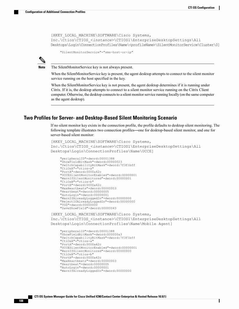
[HKEY_LOCAL_MACHINE\SOFTWARE\Cisco Systems,Inc.\Ctios\CTIOS_<instance>\CTIOS1\EnterpriseDesktopSettings\AllDesktops\Login\ConnectionProfiles\Name\<profileName>\SilentMonitorService\Cluster\0]
"SilentMonitorService"="sms-host-or-ip"
The SilentMonitorService key is not always present.
When the SilentMonitorService key is present, the agent desktop attempts to connect to the silent monitorservice running on the host specified in the key.
When the SilentMonitorService key is not present, the agent desktop determines if it is running underCitrix. If it is, the desktop attempts to connect to a silent monitor service running on the Citrix Clientcomputer. Otherwise, the desktop connects to a silent monitor service running locally (on the same computeras the agent desktop).
Note
Two Profiles for Server- and Desktop-Based Silent Monitoring ScenarioIf no silent monitor key exists in the connection profile, the profile defaults to desktop silent monitoring. Thefollowing template illustrates two connection profiles—one for desktop-based silent monitor, and one forserver-based silent monitor:
[HKEY_LOCAL_MACHINE\SOFTWARE\Cisco Systems,Inc.\Ctios\CTIOS_<instance>\CTIOS1\EnterpriseDesktopSettings\AllDesktops\Login\ConnectionProfiles\Name\UCCE]
"peripheralID"=dword:00001388"ShowFieldBitMask"=dword:00000023"SwitchCapabilityBitMask"=dword:7f3f1bff"CtiOsA"="ctios-a""PortA"=dword:0000a42c"UCCESilentMonitorEnabled"=dword:00000001"WarnIfSilentMonitored"=dword:00000001"CtiOsB"="ctios-b""PortB"=dword:0000a42c"MaxHeartbeats"=dword:00000003"Heartbeat"=dword:00000005"AutoLogin"=dword:00000001"WarnIfAlreadyLoggedIn"=dword:00000000"RejectIfAlreadyLoggedIn"=dword:00000000"TOS"=dword:00000000"SaveShowField"=dword:00000043
[HKEY_LOCAL_MACHINE\SOFTWARE\Cisco Systems,Inc.\Ctios\CTIOS_<instance>\CTIOS1\EnterpriseDesktopSettings\AllDesktops\Login\ConnectionProfiles\Name\Mobile Agent]
"peripheralID"=dword:00001388"ShowFieldBitMask"=dword:000000a3"SwitchCapabilityBitMask"=dword:7f3f1bff"CtiOsA"="ctios-a""PortA"=dword:0000a42c"UCCESilentMonitorEnabled"=dword:00000001"WarnIfSilentMonitored"=dword:00000000"CtiOsB"="ctios-b""PortB"=dword:0000a42c"MaxHeartbeats"=dword:00000003"Heartbeat"=dword:00000005"AutoLogin"=dword:00000001"WarnIfAlreadyLoggedIn"=dword:00000000
CTI OS System Manager Guide for Cisco Unified ICM/Contact Center Enterprise & Hosted Release 10.5(1)108
CTI OS ConfigurationConfiguration of Additional Connection Profiles
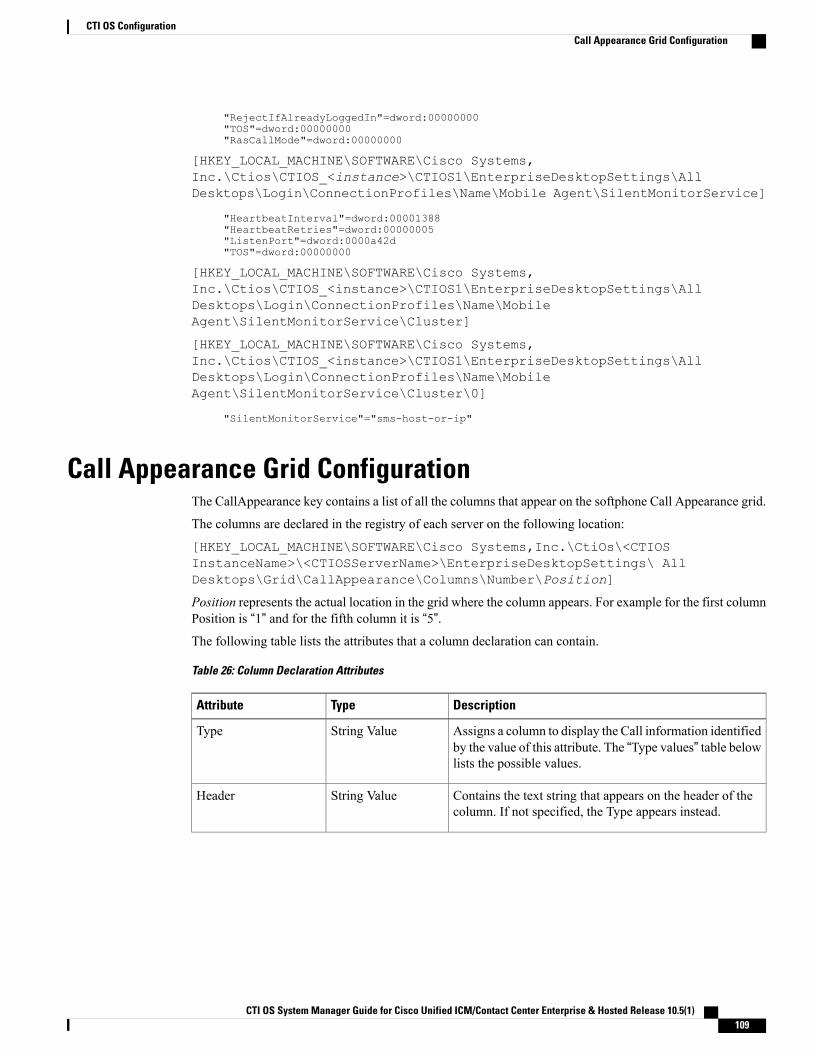
"RejectIfAlreadyLoggedIn"=dword:00000000"TOS"=dword:00000000"RasCallMode"=dword:00000000
[HKEY_LOCAL_MACHINE\SOFTWARE\Cisco Systems,Inc.\Ctios\CTIOS_<instance>\CTIOS1\EnterpriseDesktopSettings\AllDesktops\Login\ConnectionProfiles\Name\Mobile Agent\SilentMonitorService]
"HeartbeatInterval"=dword:00001388"HeartbeatRetries"=dword:00000005"ListenPort"=dword:0000a42d"TOS"=dword:00000000
[HKEY_LOCAL_MACHINE\SOFTWARE\Cisco Systems,Inc.\Ctios\CTIOS_<instance>\CTIOS1\EnterpriseDesktopSettings\AllDesktops\Login\ConnectionProfiles\Name\MobileAgent\SilentMonitorService\Cluster]
[HKEY_LOCAL_MACHINE\SOFTWARE\Cisco Systems,Inc.\Ctios\CTIOS_<instance>\CTIOS1\EnterpriseDesktopSettings\AllDesktops\Login\ConnectionProfiles\Name\MobileAgent\SilentMonitorService\Cluster\0]
"SilentMonitorService"="sms-host-or-ip"
Call Appearance Grid ConfigurationThe CallAppearance key contains a list of all the columns that appear on the softphone Call Appearance grid.
The columns are declared in the registry of each server on the following location:
[HKEY_LOCAL_MACHINE\SOFTWARE\Cisco Systems,Inc.\CtiOs\<CTIOSInstanceName>\<CTIOSServerName>\EnterpriseDesktopSettings\ AllDesktops\Grid\CallAppearance\Columns\Number\Position]
Position represents the actual location in the grid where the column appears. For example for the first columnPosition is “1” and for the fifth column it is “5”.The following table lists the attributes that a column declaration can contain.
Table 26: Column Declaration Attributes
DescriptionTypeAttribute
Assigns a column to display the Call information identifiedby the value of this attribute. The “Type values” table belowlists the possible values.
String ValueType
Contains the text string that appears on the header of thecolumn. If not specified, the Type appears instead.
String ValueHeader
CTI OS System Manager Guide for Cisco Unified ICM/Contact Center Enterprise & Hosted Release 10.5(1) 109
CTI OS ConfigurationCall Appearance Grid Configuration
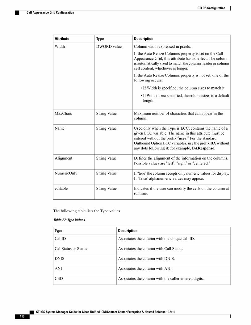
DescriptionTypeAttribute
Column width expressed in pixels.
If the Auto Resize Columns property is set on the CallAppearance Grid, this attribute has no effect. The columnis automatically sized tomatch the column header or columncell content, whichever is longer.
If the Auto Resize Columns property is not set, one of thefollowing occurs:
• If Width is specified, the column sizes to match it.
• IfWidth is not specified, the column sizes to a defaultlength.
DWORD valueWidth
Maximum number of characters that can appear in thecolumn.
String ValueMaxChars
Used only when the Type is ECC; contains the name of agiven ECC variable. The name in this attribute must beentered without the prefix “user.” For the standardOutbound Option ECC variables, use the prefixBAwithoutany dots following it; for example, BAResponse.
String ValueName
Defines the alignment of the information on the columns.Possible values are “left”, “right” or “centered.”
String ValueAlignment
If “true” the column accepts only numeric values for display.If “false” alphanumeric values may appear.
String ValueNumericOnly
Indicates if the user can modify the cells on the column atruntime.
String Valueeditable
The following table lists the Type values.
Table 27: Type Values
DescriptionType
Associates the column with the unique call ID.CallID
Associates the column with Call Status.CallStatus or Status
Associates the column with DNIS.DNIS
Associates the column with ANI.ANI
Associates the column with the caller entered digits.CED
CTI OS System Manager Guide for Cisco Unified ICM/Contact Center Enterprise & Hosted Release 10.5(1)110
CTI OS ConfigurationCall Appearance Grid Configuration
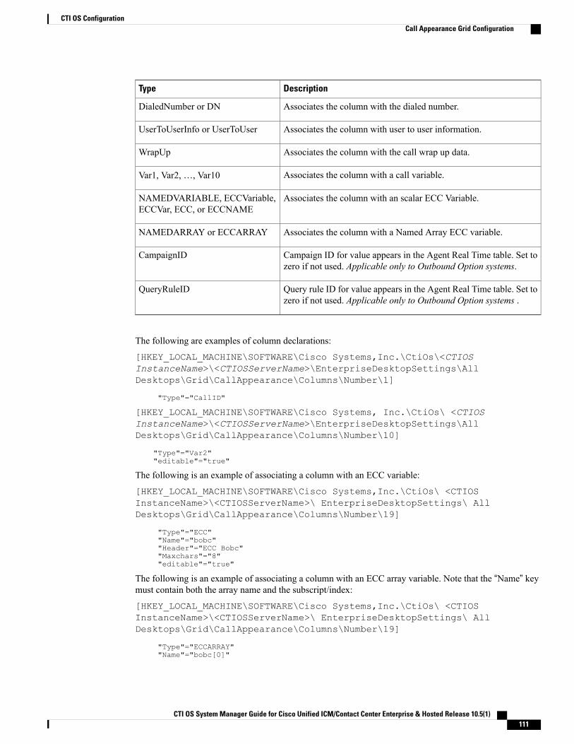
DescriptionType
Associates the column with the dialed number.DialedNumber or DN
Associates the column with user to user information.UserToUserInfo or UserToUser
Associates the column with the call wrap up data.WrapUp
Associates the column with a call variable.Var1, Var2,…, Var10
Associates the column with an scalar ECC Variable.NAMEDVARIABLE, ECCVariable,ECCVar, ECC, or ECCNAME
Associates the column with a Named Array ECC variable.NAMEDARRAY or ECCARRAY
Campaign ID for value appears in the Agent Real Time table. Set tozero if not used. Applicable only to Outbound Option systems.
CampaignID
Query rule ID for value appears in the Agent Real Time table. Set tozero if not used. Applicable only to Outbound Option systems .
QueryRuleID
The following are examples of column declarations:
[HKEY_LOCAL_MACHINE\SOFTWARE\Cisco Systems,Inc.\CtiOs\<CTIOSInstanceName>\<CTIOSServerName>\EnterpriseDesktopSettings\AllDesktops\Grid\CallAppearance\Columns\Number\1]
"Type"="CallID"
[HKEY_LOCAL_MACHINE\SOFTWARE\Cisco Systems, Inc.\CtiOs\ <CTIOSInstanceName>\<CTIOSServerName>\EnterpriseDesktopSettings\AllDesktops\Grid\CallAppearance\Columns\Number\10]
"Type"="Var2""editable"="true"
The following is an example of associating a column with an ECC variable:
[HKEY_LOCAL_MACHINE\SOFTWARE\Cisco Systems,Inc.\CtiOs\ <CTIOSInstanceName>\<CTIOSServerName>\ EnterpriseDesktopSettings\ AllDesktops\Grid\CallAppearance\Columns\Number\19]
"Type"="ECC""Name"="bobc""Header"="ECC Bobc""Maxchars"="8""editable"="true"
The following is an example of associating a column with an ECC array variable. Note that the “Name” keymust contain both the array name and the subscript/index:
[HKEY_LOCAL_MACHINE\SOFTWARE\Cisco Systems,Inc.\CtiOs\ <CTIOSInstanceName>\<CTIOSServerName>\ EnterpriseDesktopSettings\ AllDesktops\Grid\CallAppearance\Columns\Number\19]
"Type"="ECCARRAY""Name"="bobc[0]"
CTI OS System Manager Guide for Cisco Unified ICM/Contact Center Enterprise & Hosted Release 10.5(1) 111
CTI OS ConfigurationCall Appearance Grid Configuration
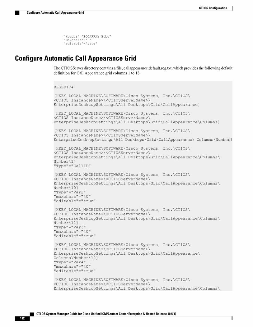
"Header"="ECCARRAY Bobc""Maxchars"="8""editable"="true"
Configure Automatic Call Appearance GridThe CTIOSServer directory contains a file, callappearance.default.reg.txt, which provides the following defaultdefinition for Call Appearance grid columns 1 to 18:
REGEDIT4
[HKEY_LOCAL_MACHINE\SOFTWARE\Cisco Systems, Inc.\CTIOS\<CTIOS InstanceName>\<CTIOSServerName>\EnterpriseDesktopSettings\All Desktops\Grid\CallAppearance]
[HKEY_LOCAL_MACHINE\SOFTWARE\Cisco Systems, Inc.\CTIOS\<CTIOS InstanceName>\<CTIOSServerName>\EnterpriseDesktopSettings\All Desktops\Grid\CallAppearance\Columns]
[HKEY_LOCAL_MACHINE\SOFTWARE\Cisco Systems, Inc.\CTIOS\<CTIOS InstanceName>\<CTIOSServerName>\EnterpriseDesktopSettings\All Desktops\Grid\CallAppearance\ Columns\Number]
[HKEY_LOCAL_MACHINE\SOFTWARE\Cisco Systems, Inc.\CTIOS\<CTIOS InstanceName>\<CTIOSServerName>\EnterpriseDesktopSettings\All Desktops\Grid\CallAppearance\Columns\Number\1]"Type"="CallID"
[HKEY_LOCAL_MACHINE\SOFTWARE\Cisco Systems, Inc.\CTIOS\<CTIOS InstanceName>\<CTIOSServerName>\EnterpriseDesktopSettings\All Desktops\Grid\CallAppearance\Columns\Number\10]"Type"="Var2""maxchars"="40""editable"="true"
[HKEY_LOCAL_MACHINE\SOFTWARE\Cisco Systems, Inc.\CTIOS\<CTIOS InstanceName>\<CTIOSServerName>\EnterpriseDesktopSettings\All Desktops\Grid\CallAppearance\Columns\Number\11]"Type"="Var3""maxchars"="40""editable"="true"
[HKEY_LOCAL_MACHINE\SOFTWARE\Cisco Systems, Inc.\CTIOS\<CTIOS InstanceName>\<CTIOSServerName>\EnterpriseDesktopSettings\All Desktops\Grid\CallAppearance\Columns\Number\12]"Type"="Var4""maxchars"="40""editable"="true"
[HKEY_LOCAL_MACHINE\SOFTWARE\Cisco Systems, Inc.\CTIOS\<CTIOS InstanceName>\<CTIOSServerName>\EnterpriseDesktopSettings\All Desktops\Grid\CallAppearance\Columns\
CTI OS System Manager Guide for Cisco Unified ICM/Contact Center Enterprise & Hosted Release 10.5(1)112
CTI OS ConfigurationConfigure Automatic Call Appearance Grid
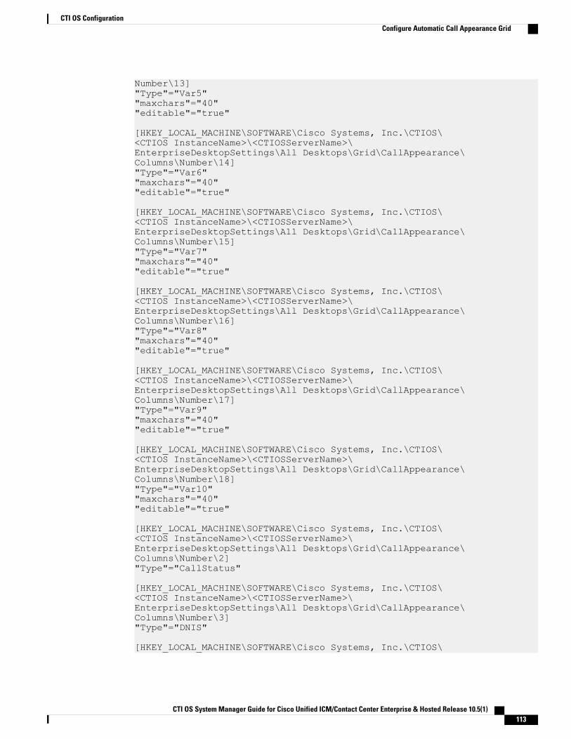
Number\13]"Type"="Var5""maxchars"="40""editable"="true"
[HKEY_LOCAL_MACHINE\SOFTWARE\Cisco Systems, Inc.\CTIOS\<CTIOS InstanceName>\<CTIOSServerName>\EnterpriseDesktopSettings\All Desktops\Grid\CallAppearance\Columns\Number\14]"Type"="Var6""maxchars"="40""editable"="true"
[HKEY_LOCAL_MACHINE\SOFTWARE\Cisco Systems, Inc.\CTIOS\<CTIOS InstanceName>\<CTIOSServerName>\EnterpriseDesktopSettings\All Desktops\Grid\CallAppearance\Columns\Number\15]"Type"="Var7""maxchars"="40""editable"="true"
[HKEY_LOCAL_MACHINE\SOFTWARE\Cisco Systems, Inc.\CTIOS\<CTIOS InstanceName>\<CTIOSServerName>\EnterpriseDesktopSettings\All Desktops\Grid\CallAppearance\Columns\Number\16]"Type"="Var8""maxchars"="40""editable"="true"
[HKEY_LOCAL_MACHINE\SOFTWARE\Cisco Systems, Inc.\CTIOS\<CTIOS InstanceName>\<CTIOSServerName>\EnterpriseDesktopSettings\All Desktops\Grid\CallAppearance\Columns\Number\17]"Type"="Var9""maxchars"="40""editable"="true"
[HKEY_LOCAL_MACHINE\SOFTWARE\Cisco Systems, Inc.\CTIOS\<CTIOS InstanceName>\<CTIOSServerName>\EnterpriseDesktopSettings\All Desktops\Grid\CallAppearance\Columns\Number\18]"Type"="Var10""maxchars"="40""editable"="true"
[HKEY_LOCAL_MACHINE\SOFTWARE\Cisco Systems, Inc.\CTIOS\<CTIOS InstanceName>\<CTIOSServerName>\EnterpriseDesktopSettings\All Desktops\Grid\CallAppearance\Columns\Number\2]"Type"="CallStatus"
[HKEY_LOCAL_MACHINE\SOFTWARE\Cisco Systems, Inc.\CTIOS\<CTIOS InstanceName>\<CTIOSServerName>\EnterpriseDesktopSettings\All Desktops\Grid\CallAppearance\Columns\Number\3]"Type"="DNIS"
[HKEY_LOCAL_MACHINE\SOFTWARE\Cisco Systems, Inc.\CTIOS\
CTI OS System Manager Guide for Cisco Unified ICM/Contact Center Enterprise & Hosted Release 10.5(1) 113
CTI OS ConfigurationConfigure Automatic Call Appearance Grid
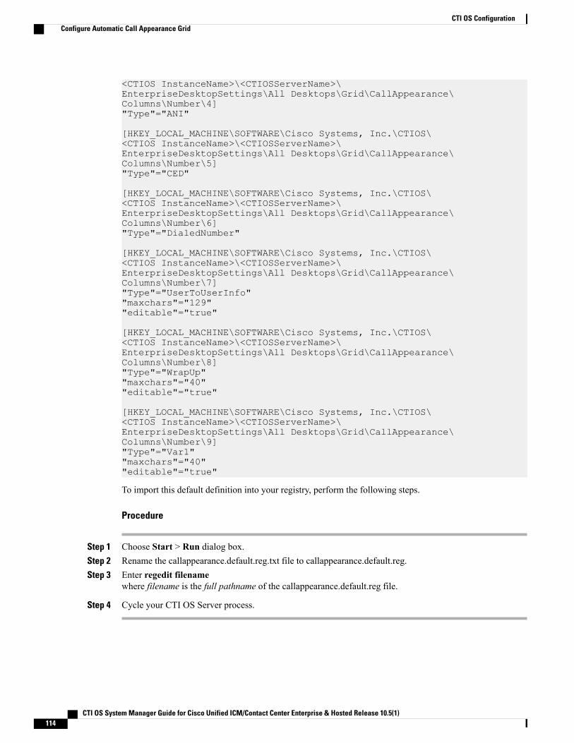
<CTIOS InstanceName>\<CTIOSServerName>\EnterpriseDesktopSettings\All Desktops\Grid\CallAppearance\Columns\Number\4]"Type"="ANI"
[HKEY_LOCAL_MACHINE\SOFTWARE\Cisco Systems, Inc.\CTIOS\<CTIOS InstanceName>\<CTIOSServerName>\EnterpriseDesktopSettings\All Desktops\Grid\CallAppearance\Columns\Number\5]"Type"="CED"
[HKEY_LOCAL_MACHINE\SOFTWARE\Cisco Systems, Inc.\CTIOS\<CTIOS InstanceName>\<CTIOSServerName>\EnterpriseDesktopSettings\All Desktops\Grid\CallAppearance\Columns\Number\6]"Type"="DialedNumber"
[HKEY_LOCAL_MACHINE\SOFTWARE\Cisco Systems, Inc.\CTIOS\<CTIOS InstanceName>\<CTIOSServerName>\EnterpriseDesktopSettings\All Desktops\Grid\CallAppearance\Columns\Number\7]"Type"="UserToUserInfo""maxchars"="129""editable"="true"
[HKEY_LOCAL_MACHINE\SOFTWARE\Cisco Systems, Inc.\CTIOS\<CTIOS InstanceName>\<CTIOSServerName>\EnterpriseDesktopSettings\All Desktops\Grid\CallAppearance\Columns\Number\8]"Type"="WrapUp""maxchars"="40""editable"="true"
[HKEY_LOCAL_MACHINE\SOFTWARE\Cisco Systems, Inc.\CTIOS\<CTIOS InstanceName>\<CTIOSServerName>\EnterpriseDesktopSettings\All Desktops\Grid\CallAppearance\Columns\Number\9]"Type"="Var1""maxchars"="40""editable"="true"
To import this default definition into your registry, perform the following steps.
Procedure
Step 1 Choose Start > Run dialog box.Step 2 Rename the callappearance.default.reg.txt file to callappearance.default.reg.Step 3 Enter regedit filename
where filename is the full pathname of the callappearance.default.reg file.
Step 4 Cycle your CTI OS Server process.
CTI OS System Manager Guide for Cisco Unified ICM/Contact Center Enterprise & Hosted Release 10.5(1)114
CTI OS ConfigurationConfigure Automatic Call Appearance Grid
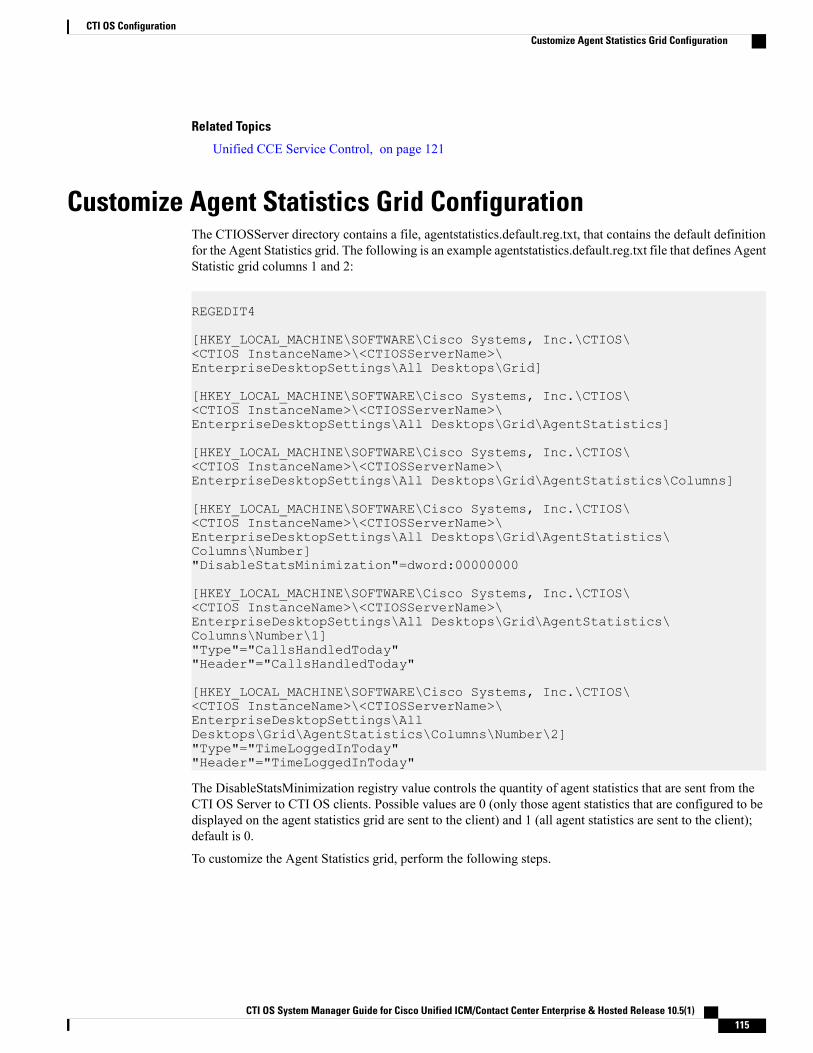
Related Topics
Unified CCE Service Control, on page 121
Customize Agent Statistics Grid ConfigurationThe CTIOSServer directory contains a file, agentstatistics.default.reg.txt, that contains the default definitionfor the Agent Statistics grid. The following is an example agentstatistics.default.reg.txt file that defines AgentStatistic grid columns 1 and 2:
REGEDIT4
[HKEY_LOCAL_MACHINE\SOFTWARE\Cisco Systems, Inc.\CTIOS\<CTIOS InstanceName>\<CTIOSServerName>\EnterpriseDesktopSettings\All Desktops\Grid]
[HKEY_LOCAL_MACHINE\SOFTWARE\Cisco Systems, Inc.\CTIOS\<CTIOS InstanceName>\<CTIOSServerName>\EnterpriseDesktopSettings\All Desktops\Grid\AgentStatistics]
[HKEY_LOCAL_MACHINE\SOFTWARE\Cisco Systems, Inc.\CTIOS\<CTIOS InstanceName>\<CTIOSServerName>\EnterpriseDesktopSettings\All Desktops\Grid\AgentStatistics\Columns]
[HKEY_LOCAL_MACHINE\SOFTWARE\Cisco Systems, Inc.\CTIOS\<CTIOS InstanceName>\<CTIOSServerName>\EnterpriseDesktopSettings\All Desktops\Grid\AgentStatistics\Columns\Number]"DisableStatsMinimization"=dword:00000000
[HKEY_LOCAL_MACHINE\SOFTWARE\Cisco Systems, Inc.\CTIOS\<CTIOS InstanceName>\<CTIOSServerName>\EnterpriseDesktopSettings\All Desktops\Grid\AgentStatistics\Columns\Number\1]"Type"="CallsHandledToday""Header"="CallsHandledToday"
[HKEY_LOCAL_MACHINE\SOFTWARE\Cisco Systems, Inc.\CTIOS\<CTIOS InstanceName>\<CTIOSServerName>\EnterpriseDesktopSettings\AllDesktops\Grid\AgentStatistics\Columns\Number\2]"Type"="TimeLoggedInToday""Header"="TimeLoggedInToday"
The DisableStatsMinimization registry value controls the quantity of agent statistics that are sent from theCTI OS Server to CTI OS clients. Possible values are 0 (only those agent statistics that are configured to bedisplayed on the agent statistics grid are sent to the client) and 1 (all agent statistics are sent to the client);default is 0.
To customize the Agent Statistics grid, perform the following steps.
CTI OS System Manager Guide for Cisco Unified ICM/Contact Center Enterprise & Hosted Release 10.5(1) 115
CTI OS ConfigurationCustomize Agent Statistics Grid Configuration
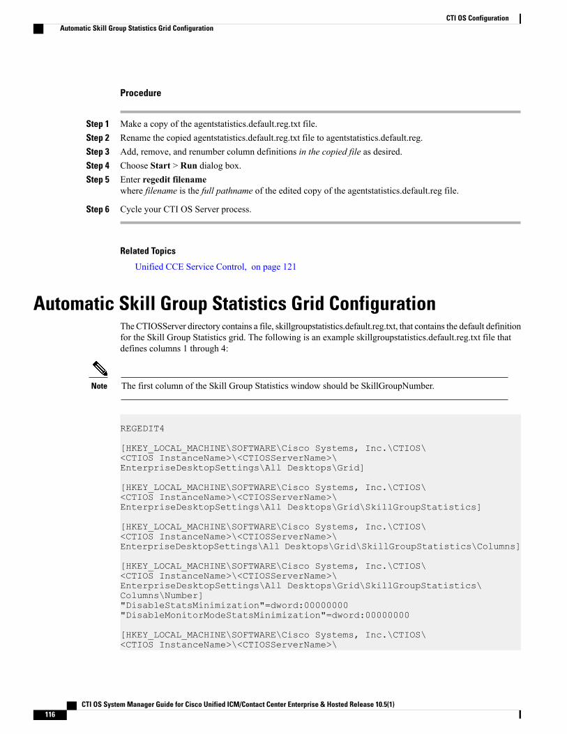
Procedure
Step 1 Make a copy of the agentstatistics.default.reg.txt file.Step 2 Rename the copied agentstatistics.default.reg.txt file to agentstatistics.default.reg.Step 3 Add, remove, and renumber column definitions in the copied file as desired.Step 4 Choose Start > Run dialog box.Step 5 Enter regedit filename
where filename is the full pathname of the edited copy of the agentstatistics.default.reg file.
Step 6 Cycle your CTI OS Server process.
Related Topics
Unified CCE Service Control, on page 121
Automatic Skill Group Statistics Grid ConfigurationThe CTIOSServer directory contains a file, skillgroupstatistics.default.reg.txt, that contains the default definitionfor the Skill Group Statistics grid. The following is an example skillgroupstatistics.default.reg.txt file thatdefines columns 1 through 4:
The first column of the Skill Group Statistics window should be SkillGroupNumber.Note
REGEDIT4
[HKEY_LOCAL_MACHINE\SOFTWARE\Cisco Systems, Inc.\CTIOS\<CTIOS InstanceName>\<CTIOSServerName>\EnterpriseDesktopSettings\All Desktops\Grid]
[HKEY_LOCAL_MACHINE\SOFTWARE\Cisco Systems, Inc.\CTIOS\<CTIOS InstanceName>\<CTIOSServerName>\EnterpriseDesktopSettings\All Desktops\Grid\SkillGroupStatistics]
[HKEY_LOCAL_MACHINE\SOFTWARE\Cisco Systems, Inc.\CTIOS\<CTIOS InstanceName>\<CTIOSServerName>\EnterpriseDesktopSettings\All Desktops\Grid\SkillGroupStatistics\Columns]
[HKEY_LOCAL_MACHINE\SOFTWARE\Cisco Systems, Inc.\CTIOS\<CTIOS InstanceName>\<CTIOSServerName>\EnterpriseDesktopSettings\All Desktops\Grid\SkillGroupStatistics\Columns\Number]"DisableStatsMinimization"=dword:00000000"DisableMonitorModeStatsMinimization"=dword:00000000
[HKEY_LOCAL_MACHINE\SOFTWARE\Cisco Systems, Inc.\CTIOS\<CTIOS InstanceName>\<CTIOSServerName>\
CTI OS System Manager Guide for Cisco Unified ICM/Contact Center Enterprise & Hosted Release 10.5(1)116
CTI OS ConfigurationAutomatic Skill Group Statistics Grid Configuration
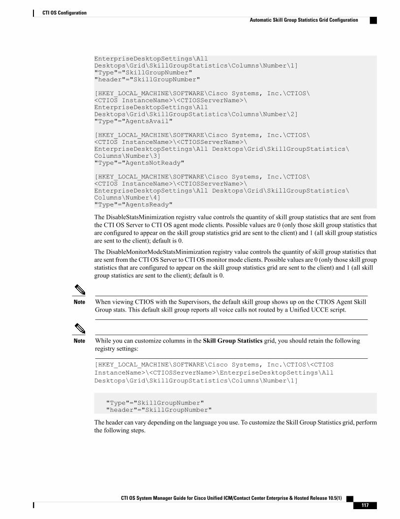
EnterpriseDesktopSettings\AllDesktops\Grid\SkillGroupStatistics\Columns\Number\1]"Type"="SkillGroupNumber""header"="SkillGroupNumber"
[HKEY_LOCAL_MACHINE\SOFTWARE\Cisco Systems, Inc.\CTIOS\<CTIOS InstanceName>\<CTIOSServerName>\EnterpriseDesktopSettings\AllDesktops\Grid\SkillGroupStatistics\Columns\Number\2]"Type"="AgentsAvail"
[HKEY_LOCAL_MACHINE\SOFTWARE\Cisco Systems, Inc.\CTIOS\<CTIOS InstanceName>\<CTIOSServerName>\EnterpriseDesktopSettings\All Desktops\Grid\SkillGroupStatistics\Columns\Number\3]"Type"="AgentsNotReady"
[HKEY_LOCAL_MACHINE\SOFTWARE\Cisco Systems, Inc.\CTIOS\<CTIOS InstanceName>\<CTIOSServerName>\EnterpriseDesktopSettings\All Desktops\Grid\SkillGroupStatistics\Columns\Number\4]"Type"="AgentsReady"
The DisableStatsMinimization registry value controls the quantity of skill group statistics that are sent fromthe CTI OS Server to CTI OS agent mode clients. Possible values are 0 (only those skill group statistics thatare configured to appear on the skill group statistics grid are sent to the client) and 1 (all skill group statisticsare sent to the client); default is 0.
The DisableMonitorModeStatsMinimization registry value controls the quantity of skill group statistics thatare sent from the CTI OS Server to CTI OSmonitor mode clients. Possible values are 0 (only those skill groupstatistics that are configured to appear on the skill group statistics grid are sent to the client) and 1 (all skillgroup statistics are sent to the client); default is 0.
When viewing CTIOS with the Supervisors, the default skill group shows up on the CTIOS Agent SkillGroup stats. This default skill group reports all voice calls not routed by a Unified UCCE script.
Note
While you can customize columns in the Skill Group Statistics grid, you should retain the followingregistry settings:
Note
[HKEY_LOCAL_MACHINE\SOFTWARE\Cisco Systems, Inc.\CTIOS\<CTIOSInstanceName>\<CTIOSServerName>\EnterpriseDesktopSettings\AllDesktops\Grid\SkillGroupStatistics\Columns\Number\1]
"Type"="SkillGroupNumber""header"="SkillGroupNumber"
The header can vary depending on the language you use. To customize the Skill Group Statistics grid, performthe following steps.
CTI OS System Manager Guide for Cisco Unified ICM/Contact Center Enterprise & Hosted Release 10.5(1) 117
CTI OS ConfigurationAutomatic Skill Group Statistics Grid Configuration
Procedure
Step 1 Make a copy of the skillgroupstatistics.default.reg.txt file.Step 2 Rename the copied skillgroupstatistics.default.reg.txt file to skillgroupstatistics.default.reg.Step 3 Add, remove, and renumber column definitions in the copied file as desired.Step 4 Open the Windows Start > Run dialog box.Step 5 Enter regedit filename
where filename is the full pathname of the edited copy of the skillgroupstatistics.default.reg file.
Step 6 Cycle your CTI OS Server process.
Related Topics
Unified CCE Service Control, on page 121
Configure Additional PeripheralsThe Peripheral Identifier screen in CTI OS Server setup lets you supply peripheral information for a singleperipheral only. To configure additional peripherals, perform the following steps.
Procedure
Step 1 Define a registry key for the peripheral in [Server\Peripherals\ PERIPHERAL_LOGICAL_NAME].Step 2 Create a connection profile for the peripheral.
The value that you specify for Peripheral ID in the Peripherals registry key definitionmustmatch the valuethat you specify for Peripheral ID in the connection profile definition.
Note
Related Topics
Peripherals Registry Key, on page 99ConnectionProfiles Registry Key, on page 103
Quality of Service/Type of ServiceCTI OS supports “Type of Service” ToS; however, ToS is not supported for Siebel communications.The following connections/components support Qos/ToS:
• CTI OS Server to CTI OS Client.
• CTI OS Client (C++ CIL only) to CTI OS Server.
CTI OS System Manager Guide for Cisco Unified ICM/Contact Center Enterprise & Hosted Release 10.5(1)118
CTI OS ConfigurationConfigure Additional Peripherals
For CTI OS, TOS tagging is not implemented in the Java or .NET (C#) CILs. As stated above, a system usingthese could support one-way tagging from server to client, but traffic from the client to the server is sent ona best-effort basis.
CTI OS supports the marking of TCP/IP packets with ToS. This allows for preferential treatment (for example,class AF31 for assured forwarding) of CTI signaling traffic if the network is configured to support this QoSscheme.
By default, CTI OS does not mark packets, which means that the traffic is sent with "best effort" (ToS = 0).
To turn on the ToS markings, you must configure certain registry keys. In general, ToS effects only outgoingpackets. For example, the CTI OS Server can send packets with ToS markings for assured forwarding to CTIOS clients. However, that does not imply that CTI OS clients must also send their network traffic with thesame ToS value to the CTI OS Server. CTI OS clients could in fact send their traffic on a best-effort basis,which would mean that ToS is only active one way. Most likely, though, ToS is configured the same for bothdirections.
Basic ConfigurationTo turn on ToS with AF31 for bidirectional communications, add/modify some registry keys for CTI OSServer.
1 The following key turns on marking of packets CTI OS Server sends to CTI OS clients:
HKEY_LOCAL_MACHINE\SOFTWARE\Cisco Systems,Inc.\Ctios\<customer-instance>\CTIOS1\Server\Connections"TOS"=dword:00000068
The dword value above is listed in hexadecimal format (decimal 104).Note
2 This registry key turns on markings of packets sent from the client to the server:
HKEY_LOCAL_MACHINE\SOFTWARE\Cisco Systems,Inc.\Ctios\<customer-instance>\CTIOS1\EnterpriseDesktopSettings\AllDesktops\Login\ConnectionProfiles\Name\UCCE<or other profile name>"TOS"=dword:00000068
3 This key turns on TOS marking for Silent Monitor packets. Note, for a silent monitor stream a differentclass (real-time/voice) with a different TOS value (Hex B8) is suggested:
HKEY_LOCAL_MACHINE\SOFTWARE\Cisco Systems,Inc.\Ctios\<customer-instance>\CTIOS1\EnterpriseDesktopSettings\AllDesktops\UCCESilentMonitor\Name\Settings "TOS"=dword:000000B8
Important Additional Configuration InformationEnsure the following registry key in Windows Server 2008 R2 is as follows:
HKEY_LOCAL_MACHINE\SYSTEM\CurrentControlSet\Services\TcpIp\Parameters"DisableUserTOSSetting"=dword:00000000
CTI OS System Manager Guide for Cisco Unified ICM/Contact Center Enterprise & Hosted Release 10.5(1) 119
CTI OS ConfigurationBasic Configuration

Caveats• For the ToS to become effective, you must configure the network (specifically the routers) to treat packetswith ToS markings preferentially.
• The traffic between the CTI OS Server and CTI OS clients may include types of data that do not qualifyfor AF31 type of service. AF31 is suggested for signaling traffic. For example, a calldelivered eventsent from the CTI OS Server is time critical as is a potential Answer request sent from the client inresponse in order to answer an alerting call. However, the CTI OS Server can also send statistics toclients and this type of data is not suggested for AF31. However, because CTI OS sends all traffic onthe same connection, either all packets are marked or none. Therefore, you must turn off CTI OSSkillgroupstatistics with TOS enabled.
•When hardphones are used with silent monitoring, the switch in the phone overrides the TOS markingto 0. This affects both silent monitor and CTI OS client to CTI OS Server traffic. (It does not affect CTIOS Server to CTI OS client traffic.) To correct this problem, write ACL to classify traffic based onTCP/UDP port number from the endpoint.
CTI OS System Manager Guide for Cisco Unified ICM/Contact Center Enterprise & Hosted Release 10.5(1)120
CTI OS ConfigurationCaveats
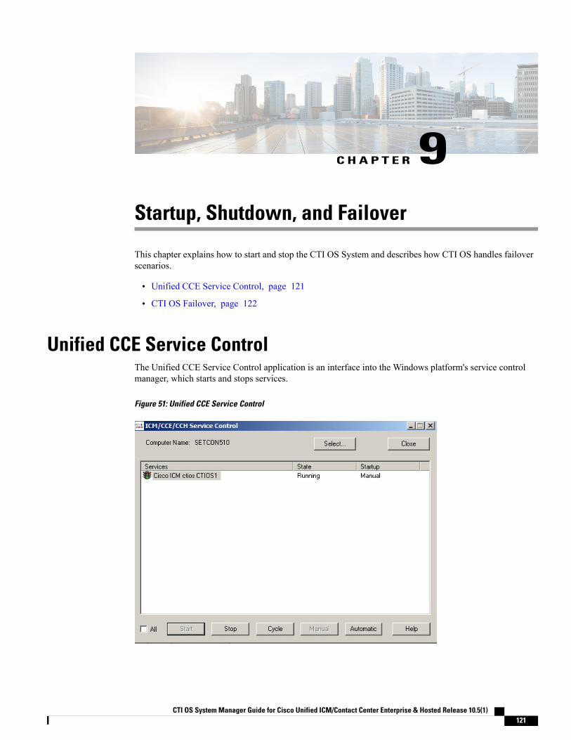
C H A P T E R 9Startup, Shutdown, and Failover
This chapter explains how to start and stop the CTI OS System and describes how CTI OS handles failoverscenarios.
• Unified CCE Service Control, page 121
• CTI OS Failover, page 122
Unified CCE Service ControlThe Unified CCE Service Control application is an interface into the Windows platform's service controlmanager, which starts and stops services.
Figure 51: Unified CCE Service Control
CTI OS System Manager Guide for Cisco Unified ICM/Contact Center Enterprise & Hosted Release 10.5(1) 121
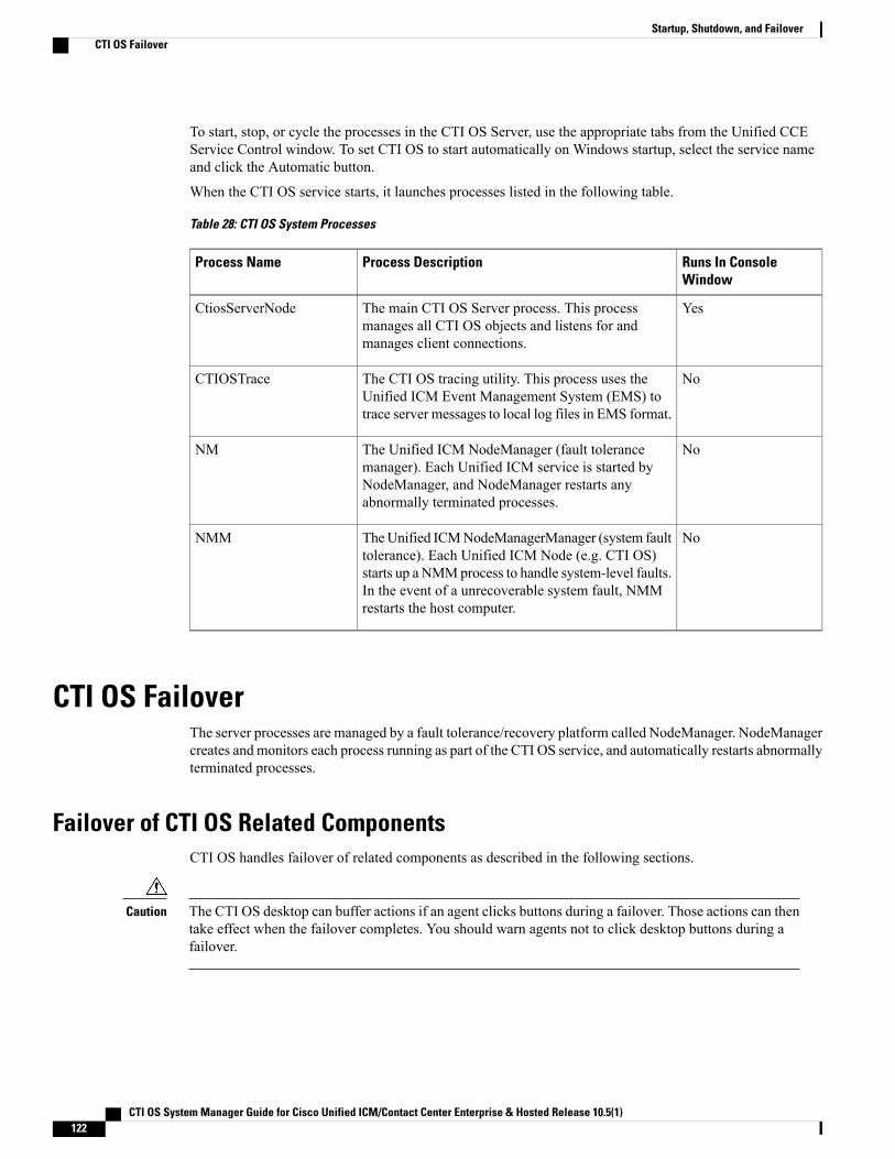
To start, stop, or cycle the processes in the CTI OS Server, use the appropriate tabs from the Unified CCEService Control window. To set CTI OS to start automatically on Windows startup, select the service nameand click the Automatic button.
When the CTI OS service starts, it launches processes listed in the following table.
Table 28: CTI OS System Processes
Runs In ConsoleWindow
Process DescriptionProcess Name
YesThe main CTI OS Server process. This processmanages all CTI OS objects and listens for andmanages client connections.
CtiosServerNode
NoThe CTI OS tracing utility. This process uses theUnified ICM Event Management System (EMS) totrace server messages to local log files in EMS format.
CTIOSTrace
NoThe Unified ICM NodeManager (fault tolerancemanager). Each Unified ICM service is started byNodeManager, and NodeManager restarts anyabnormally terminated processes.
NM
NoTheUnified ICMNodeManagerManager (system faulttolerance). Each Unified ICM Node (e.g. CTI OS)starts up a NMMprocess to handle system-level faults.In the event of a unrecoverable system fault, NMMrestarts the host computer.
NMM
CTI OS FailoverThe server processes are managed by a fault tolerance/recovery platform called NodeManager. NodeManagercreates and monitors each process running as part of the CTI OS service, and automatically restarts abnormallyterminated processes.
Failover of CTI OS Related ComponentsCTI OS handles failover of related components as described in the following sections.
The CTI OS desktop can buffer actions if an agent clicks buttons during a failover. Those actions can thentake effect when the failover completes. You should warn agents not to click desktop buttons during afailover.
Caution
CTI OS System Manager Guide for Cisco Unified ICM/Contact Center Enterprise & Hosted Release 10.5(1)122
Startup, Shutdown, and FailoverCTI OS Failover

IP PhonesIf an IP phone goes out of service, CTI OS sends an event to all soft phones associated with the IP phone thattheir IP phone is out of service. In addition, the affected softphones display the message “Offline.”When theIP phone is back in service, agents must manually log in.
SwitchesIf a switch goes out of service, CTI OS sends an event to all softphones associated with the switch that theswitch is offline. In addition, the affected softphones display the message “Offline.”When the switch is backin service, agents must manually sign in.
Peripheral GatewayBecause the Peripheral Gateway (PG) is a fault-tolerant process pair, CTI OS is not affected if the PG merelyswitches active sides. If the PG goes offline, CTI OS sends an “Offline” message to each softphone client.
CTI Server FailureOn a CTI Server failure, the CTI OS Server usually reconnects almost immediately to the redundant CTIServer. If reconnection to the redundant CTI Server is not possible, the CTI OS Server sends a failure responseto any requests made to the CTI Server.
In addition, CTI OS sends an event message to all softphone clients. On receipt of this message, the softphoneclients display an “Offline” message.When the CTI Server comes back online, CTI OS performs a snapshot of all agents, devices, and calls toreestablish state information.
CTI OS Server FailureOn aCTIOS Server failure, CTI OS disconnects all softphones from the failed CTI OS Server. These softphonesattempt to reconnect automatically to another CTI OS Server; if reconnection is not possible, CTI OS sendsan event message to all softphone clients. On receipt of this message, the softphone clients display an “Offline”message.
NodeManager restarts the CTI OS Server. When the CTI OS Server process comes back online, CTI OSperforms a snapshot of all agents, devices, and calls to reestablish state information.
CTI OS System Manager Guide for Cisco Unified ICM/Contact Center Enterprise & Hosted Release 10.5(1) 123
Startup, Shutdown, and FailoverFailover of CTI OS Related Components

CTI OS System Manager Guide for Cisco Unified ICM/Contact Center Enterprise & Hosted Release 10.5(1)124
Startup, Shutdown, and FailoverFailover of CTI OS Related Components
C H A P T E R 10Peripheral-Specific Support
This chapter provides information on the Time Division Multiplexing (TDM) peripherals supported by CTIOS.
Different peripheral manufacturers provide varying levels of support for CTI specific features. You musttake these differences into account when writing a CTI OS client application. As far as possible, the CTI OSServer and agent desktop simulate the hardphone behavior of the peripheral in question. The CTI OSSupervisor Desktop for UCCE is specific to UCCE and is currently not supported on the TDM switchesbecause they do not, in general, provide the Supervisory features that UCCE provides.
The peripherals mentioned in this chapter are the ones that CTI OS supports. For more information aboutall peripherals supported by the Cisco CTI Server, see the Cisco Unified ICM CTI Programmer's Guide.Please contact Cisco CTI Product Management if you are interested in CTI OS support for a peripheralnot mentioned here.
Note
This chapter provides the following information:
• Peripheral-specific equivalents for some common Unified ICM terms
• A list of Unified ICM features that some peripherals do not support
• A table of CTI call event types that are unavailable for different peripheral types
• A table of CTI OS client control requests that are unsupported by different peripheral types
• Differences and limitations in the level of CTI support provided by various peripherals—including alist of CTI Server agent states and the corresponding terminology/functionality associated with thevarious peripherals
• General Unified ICM Support, page 125
• CTI OS Support, page 127
General Unified ICM SupportThis section describes differences in how various peripherals implement Unified ICM functionality.
CTI OS System Manager Guide for Cisco Unified ICM/Contact Center Enterprise & Hosted Release 10.5(1) 125
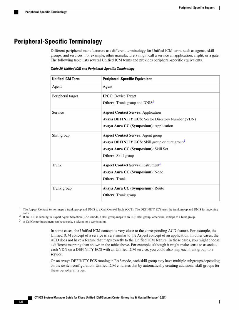
Peripheral-Specific TerminologyDifferent peripheral manufacturers use different terminology for Unified ICM terms such as agents, skillgroups, and services. For example, other manufacturers might call a service an application, a split, or a gate.The following table lists several Unified ICM terms and provides peripheral-specific equivalents.
Table 29: Unified ICM and Peripheral-Specific Terminology
Peripheral-Specific EquivalentUnified ICM Term
AgentAgent
IPCC: Device Target
Others: Trunk group and DNIS1Peripheral target
Aspect Contact Server: Application
Avaya DEFINITY ECS: Vector Directory Number (VDN)
Avaya Aura CC (Symposium): Application
Service
Aspect Contact Server: Agent group
Avaya DEFINITY ECS: Skill group or hunt group2
Avaya Aura CC (Symposium): Skill Set
Others: Skill group
Skill group
Aspect Contact Server: Instrument3
Avaya Aura CC (Symposium): None
Others: Trunk
Trunk
Avaya Aura CC (Symposium): Route
Others: Trunk group
Trunk group
1 The Aspect Contact Server maps a trunk group and DNIS to a Call Control Table (CCT). The DEFINITY ECS uses the trunk group and DNIS for incomingcalls.
2 If an ECS is running in Expert Agent Selection (EAS) mode, a skill group maps to an ECS skill group; otherwise, it maps to a hunt group.3 A CallCenter instrument can be a trunk, a teleset, or a workstation.
In some cases, the Unified ICM concept is very close to the corresponding ACD feature. For example, theUnified ICM concept of a service is very similar to the Aspect concept of an application. In other cases, theACD does not have a feature that maps exactly to the Unified ICM feature. In these cases, you might choosea different mapping than shown in the table above. For example, although it might make sense to associateeach VDN on a DEFINITY ECS with an Unified ICM service, you could also map each hunt group to aservice.
On an Avaya DEFINITYECS running in EASmode, each skill groupmay havemultiple subgroups dependingon the switch configuration. Unified ICM emulates this by automatically creating additional skill groups forthese peripheral types.
CTI OS System Manager Guide for Cisco Unified ICM/Contact Center Enterprise & Hosted Release 10.5(1)126
Peripheral-Specific SupportPeripheral-Specific Terminology
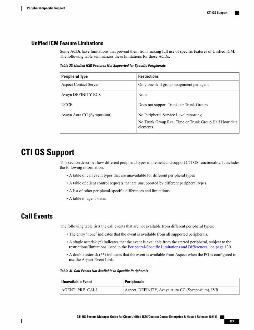
Unified ICM Feature LimitationsSome ACDs have limitations that prevent them from making full use of specific features of Unified ICM.The following table summarizes these limitations for those ACDs.
Table 30: Unified ICM Features Not Supported for Specific Peripherals
RestrictionsPeripheral Type
Only one skill group assignment per agentAspect Contact Server
NoneAvaya DEFINITY ECS
Does not support Trunks or Trunk GroupsUCCE
No Peripheral Service Level reporting
No Trunk Group Real Time or Trunk Group Half Hour dataelements
Avaya Aura CC (Symposium)
CTI OS SupportThis section describes how different peripheral types implement and support CTI OS functionality. It includesthe following information:
• A table of call event types that are unavailable for different peripheral types
• A table of client control requests that are unsupported by different peripheral types
• A list of other peripheral-specific differences and limitations
• A table of agent states
Call EventsThe following table lists the call events that are not available from different peripheral types:
• The entry “none” indicates that the event is available from all supported peripherals.
• A single asterisk (*) indicates that the event is available from the starred peripheral, subject to therestrictions/limitations listed in the Peripheral-Specific Limitations and Differences, on page 130.
• A double asterisk (**) indicates that the event is available from Aspect when the PG is configured touse the Aspect Event Link.
Table 31: Call Events Not Available to Specific Peripherals
PeripheralsUnavailable Event
Aspect, DEFINITY, Avaya Aura CC (Symposium), IVRAGENT_PRE_CALL
CTI OS System Manager Guide for Cisco Unified ICM/Contact Center Enterprise & Hosted Release 10.5(1) 127
Peripheral-Specific SupportCTI OS Support

PeripheralsUnavailable Event
Aspect, DEFINITY, Avaya Aura CC (Symposium), IVRAGENT_PRE_CALL_ABORT
NoneAGENT_STATE
NoneBEGIN_CALL
Aspect*CALL_ CLEARED
Aspect**,IVRCALL_CONFERENCED
NoneCALL_CONNECTION_CLEARED
NoneCALL_DATA_UPDATE
Aspect*CALL_DELIVERED
DEFINITY, Avaya Aura CC (Symposium), UCCE, IVRCALL_DEQUEUED
Aspect, UCCE, Avaya Aura CC (Symposium)CALL_DIVERTED
IVRCALL_ESTABLISHED
Aspect, Avaya Aura CC (Symposium), IVRCALL_FAILED
Aspect**, IVRCALL_HELD
Aspect, DEFINITY*, Avaya Aura CC (Symposium)CALL_ORIGINATED
UCCE, IVRCALL_QUEUED
Aspect, Avaya Aura CC (Symposium), IVRCALL_REACHED_NETWORK
Aspect**, IVRCALL_RETRIEVED
Aspect**, DEFINITY*, IVRCALL_ SERVICE_ INITIATED
IVRCALL_TRANSFERRED
UCCECALL_TRANSLATION_ ROUTE
NoneEND_CALL
Aspect, Avaya Aura CC (Symposium), IVRRTP_STARTED_EVENT
Aspect, Avaya Aura CC (Symposium), IVRRTP_STOPPED_EVENT
NoneSYSTEM
CTI OS System Manager Guide for Cisco Unified ICM/Contact Center Enterprise & Hosted Release 10.5(1)128
Peripheral-Specific SupportCall Events
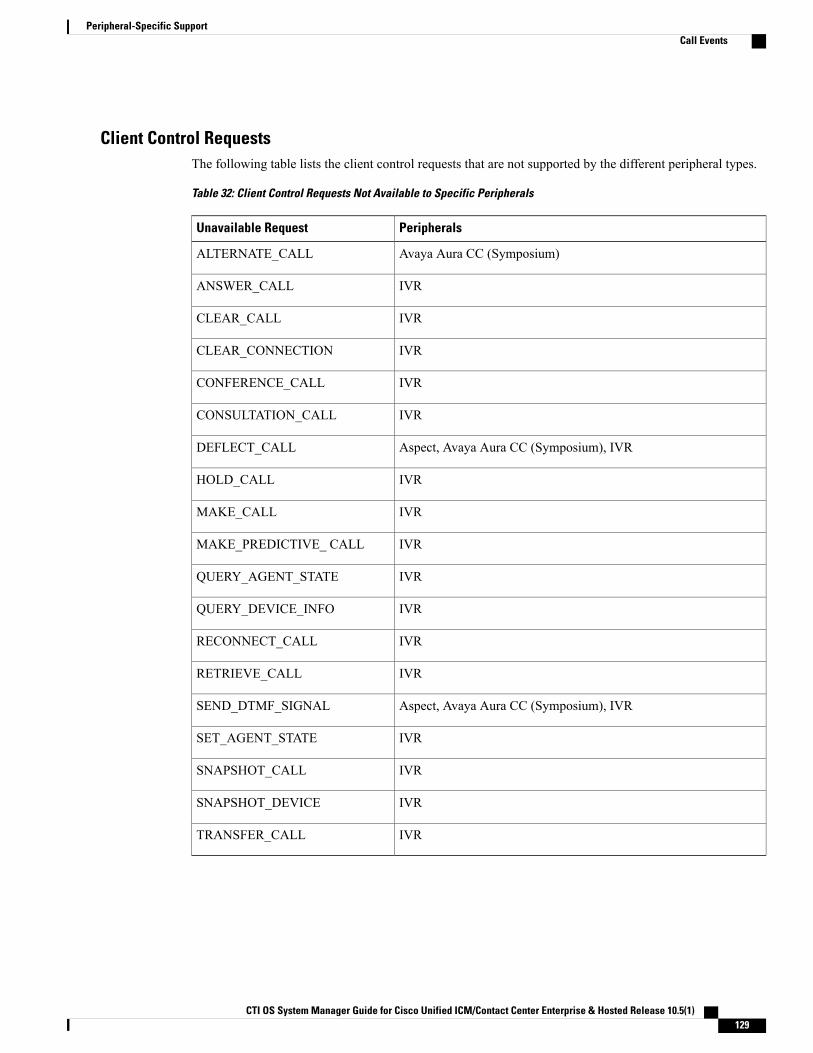
Client Control RequestsThe following table lists the client control requests that are not supported by the different peripheral types.
Table 32: Client Control Requests Not Available to Specific Peripherals
PeripheralsUnavailable Request
Avaya Aura CC (Symposium)ALTERNATE_CALL
IVRANSWER_CALL
IVRCLEAR_CALL
IVRCLEAR_CONNECTION
IVRCONFERENCE_CALL
IVRCONSULTATION_CALL
Aspect, Avaya Aura CC (Symposium), IVRDEFLECT_CALL
IVRHOLD_CALL
IVRMAKE_CALL
IVRMAKE_PREDICTIVE_ CALL
IVRQUERY_AGENT_STATE
IVRQUERY_DEVICE_INFO
IVRRECONNECT_CALL
IVRRETRIEVE_CALL
Aspect, Avaya Aura CC (Symposium), IVRSEND_DTMF_SIGNAL
IVRSET_AGENT_STATE
IVRSNAPSHOT_CALL
IVRSNAPSHOT_DEVICE
IVRTRANSFER_CALL
CTI OS System Manager Guide for Cisco Unified ICM/Contact Center Enterprise & Hosted Release 10.5(1) 129
Peripheral-Specific SupportCall Events
Peripheral-Specific Limitations and DifferencesThis section lists CTI OS-related restrictions and implementation differences for various peripherals.
Note • MAKE_CALL is only supported when the agent is in the NotReady state for an UCCE peripheral.
• MAKE_CALL is not supported for the remaining peripherals supported by CTI OS.
• The call continues to be active even after a party is released from the conference.
Aspect Contact Server• AgentExtension and AgentInstrument are defined as the port number that the teleset is connected to.
• Events marked by an asterisk (*) are available when the PG is configured to use the Aspect EventLink.
• Call Alerting (Call Delivered, LocalConnectionState = LCS_ALERTING) is availablewhen the EventLinkis used.
• Outbound calls on some trunk types do not always provide Call Cleared events. Interflow calls that areaccepted, but handled by the originating site, also sometimes do not provide Call Cleared events.
• Outbound calls require that the CallPlacementType be specified in an outbound request.
• Conference calls can have a maximum of three parties.
• In a single-step/blind transfer of a call, the initial call must come in over a trunk (be a CCT call) and thedialed number must go to a CCT.
• In a regular call transfer, the consult call can be either a CCT call or an agent_inside call.
• Alternate call operations require that the initial call be a CCT call. The second call (consult call) can beeither a CCT call or an agent_inside call.
• In the MAKE_PREDICTIVE_CALL_REQmessage, the AnswerDetectControl1 field must contain thebinary value of the Application Bridge AD_PARAM setting, and the AnswerDetectControl2 field mustcontain the binary value of the Application Bridge ANS_MAP setting.
• Transfer and Conference behavior is modeled after hardphone behavior. To initiate a Transfer or aConference, you must first use the MakeCall control (Transfer Init and Conference Init buttons areunavailable at this point) to make a second (consult) call. After you make this call, the Transfer Completeand Conference Complete buttons become available to complete the desired action.
Avaya DEFINITY ECS• AgentExtension and AgentInstrument are defined as the station extension.
• DEFINITY ECS events are the same with or without EAS (Expert Agent Selection).
• Both EAS and non-EAS versions maintain a list of preconfigured agent groups. When you log in withEAS, the agent is automatically logged in to all preconfigured Agent groups. When you log in withoutEAS, the agent is logged in to only those groups that you specify in the login request.
CTI OS System Manager Guide for Cisco Unified ICM/Contact Center Enterprise & Hosted Release 10.5(1)130
Peripheral-Specific SupportPeripheral-Specific Limitations and Differences
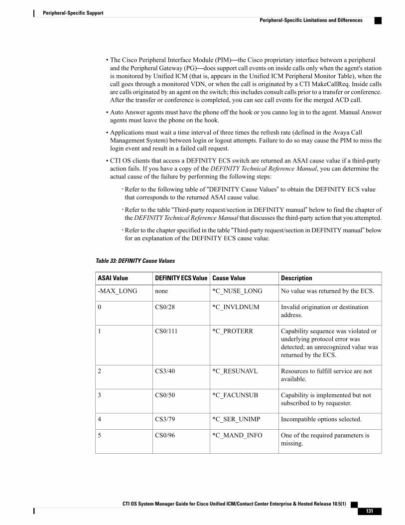
• The Cisco Peripheral Interface Module (PIM)—the Cisco proprietary interface between a peripheraland the Peripheral Gateway (PG)—does support call events on inside calls only when the agent's stationis monitored by Unified ICM (that is, appears in the Unified ICM Peripheral Monitor Table), when thecall goes through a monitored VDN, or when the call is originated by a CTI MakeCallReq. Inside callsare calls originated by an agent on the switch; this includes consult calls prior to a transfer or conference.After the transfer or conference is completed, you can see call events for the merged ACD call.
• Auto Answer agents must have the phone off the hook or you canno log in to the agent. Manual Answeragents must leave the phone on the hook.
• Applications must wait a time interval of three times the refresh rate (defined in the Avaya CallManagement System) between login or logout attempts. Failure to do so may cause the PIM to miss thelogin event and result in a failed call request.
• CTI OS clients that access a DEFINITY ECS switch are returned an ASAI cause value if a third-partyaction fails. If you have a copy of the DEFINITY Technical Reference Manual, you can determine theactual cause of the failure by performing the following steps:
◦Refer to the following table of “DEFINITY Cause Values” to obtain the DEFINITY ECS valuethat corresponds to the returned ASAI cause value.
◦Refer to the table “Third-party request/section in DEFINITY manual” below to find the chapter oftheDEFINITY Technical ReferenceManual that discusses the third-party action that you attempted.
◦Refer to the chapter specified in the table “Third-party request/section in DEFINITYmanual” belowfor an explanation of the DEFINITY ECS cause value.
Table 33: DEFINITY Cause Values
DescriptionCause ValueDEFINITY ECS ValueASAI Value
No value was returned by the ECS.*C_NUSE_LONGnone-MAX_LONG
Invalid origination or destinationaddress.
*C_INVLDNUMCS0/280
Capability sequence was violated orunderlying protocol error wasdetected; an unrecognized value wasreturned by the ECS.
*C_PROTERRCS0/1111
Resources to fulfill service are notavailable.
*C_RESUNAVLCS3/402
Capability is implemented but notsubscribed to by requester.
*C_FACUNSUBCS0/503
Incompatible options selected.*C_SER_UNIMPCS3/794
One of the required parameters ismissing.
*C_MAND_INFOCS0/965
CTI OS System Manager Guide for Cisco Unified ICM/Contact Center Enterprise & Hosted Release 10.5(1) 131
Peripheral-Specific SupportPeripheral-Specific Limitations and Differences

DescriptionCause ValueDEFINITY ECS ValueASAI Value
Value specified in parameter is notallowed or defined.
*C_INVLDIECS0/1006
Domain or call is being monitored byanother adjunct.
*C_SERV_UNAVILCS3/637
Call is no longer in active state.*C_CALLID_TERMCS3/868
Message not compatible with callstate.
*C_INCOM_STCS0/989
Invalid call identifier (sao_id alsoknown as cluster_id) used or call doesnot exist.
*C_INVALID_CRVCS0/8110
Incompatible options used to establishthe call.
*C_INCOM_OPTCS3/8011
Timer expired.*C_REC_TIMERCS0/10212
Agent not logged in to split.*C_NOLOGINCS3/1513
Agent not member of specified splitor split number specified incorrectly.
*C_NOSPLIT_MEMCS3/1114
Domain or call is being monitored byanother adjunct.
*C_USER_BUSYCS0/1715
Originating address does not respondto service.
*C_NOUSE_RESPCS0/1816
Permission checks for service havefailed.
*C_PERM_DENIEDCS3/4317
Association terminated becauseservice is not active.
*C_CLUST_TERMCS3/8718
Domain was removed byadministration.
*C_OUT_OF_SERVCS3/2719
Agent not in compatible state.*C_INCS_AGT_STCS3/1220
Agent logged in to maximum numberof splits.
*C_MAXLOGINCS3/1321
Invalid login password.*C_INC_PASWDCS3/1422
Request to put agent in the state thatthe agent is already in.
*C_AGT_STATECS3/1623
CTI OS System Manager Guide for Cisco Unified ICM/Contact Center Enterprise & Hosted Release 10.5(1)132
Peripheral-Specific SupportPeripheral-Specific Limitations and Differences

DescriptionCause ValueDEFINITY ECS ValueASAI Value
ACD not provisioned or optioned.*C_BAD_ADMINCS3/4124
Normal termination; call routedsuccessfully.
*C_NORMALCS0/1625
Association terminated because ofnetwork congestion.
*C_NETCONJCS0/4226
Unknown information elementdetected.
*C_BAD_IECS0/9927
Queue is full.*C_QUEFULLCS3/2228
Reorder/Denial.C_REORDER_DENIAL
CS3/4229
Administration is in progress; requestcannot be serviced.
C_ADMIN_PROGRESS
CS3/4630
The ECS has rejected a request fromthe adjunct.
C_FEATURE_REJECTED
CS3/5331
Unassigned number.C_UNASSIGNED_NUM
CS0/132
Call rejected.C_CALL_ REJECTEDCS0/2133
Number changed.C_NUM_ CHANGEDCS0/2234
Normal, unspecified.C_NORMAL_UNSPECIF
CS0/3135
No circuit or channel available.C_NO_CIRCUITCS0/3436
Temporary Failure.C_TEMP_FAILURECS0/4137
Bearer capability not presentlyavailable.
C_BEARER_CAP_UNAVAIL
CS0/5838
Incompatible destination.C_INCOMPAT_DESTINATION
CS0/8839
Invalid message, unspecified(backward compatibility).
C_INVALID_MESSAGE
CS0/9540
Message nonexistent/ notimplemented.
C_NON_EXIST_MESSAGE
CS0/9741
Unspecified.C_UNSPECIFIEDCS0/12742
CTI OS System Manager Guide for Cisco Unified ICM/Contact Center Enterprise & Hosted Release 10.5(1) 133
Peripheral-Specific SupportPeripheral-Specific Limitations and Differences

DescriptionCause ValueDEFINITY ECS ValueASAI Value
No answer.C_NO_ANSWERCS3/1943
Trunks not available.C_NO_TRUNKSCS3/2044
Classifiers not available.C_NO_ CLASSIFIERSCS3/2145
Redirected.C_REDIRECTCS3/3046
Network out of order.C_NETWORK_OUT_OF_ORDER
CS3/3847
Undefined value returned from theECS.
*C_CAUSE_UNKNOWN
Undefined48
Outgoing call was barred.*C_OUT_CALL_BARRED
CS0/5249
Call remains in queue.C_REMAINS_IN_QCS3/2350
Bearer service not implemented.C_BEARER_SVC_NOT_IMPL
CS0/6551
Assumed answer based on internaltimer.
C_TIMED_ ANSWERCS3/1752
Voice energy detected by the ECS.C_VOICE_ENERGY_ANSWER
CS3/1853
Channel or tone do not exist (no toneconnected to the specified call).
C_NO_TONE_CHANNEL
CS0/8254
Answering machine detected.C_ANSWERING_MACHINE
CS3/2455
Facility rejected.C_FACILITY_REJECTED
CS0/2956
Redirection cause.C_FORWARD_ BUSYCS3/2557
Redirection cause.C_COVER_BUSYCS3/2658
Redirection cause.C_COV_DONT_ ANSCS3/2859
Redirection cause.C_FORWARD_ALLCS3/3160
Single-Step Conference listen only.C_LISTEN_ONLYCS3/861
Single-Step Conference listen-talk.C_LISTEN_TALKCS3/962
CTI OS System Manager Guide for Cisco Unified ICM/Contact Center Enterprise & Hosted Release 10.5(1)134
Peripheral-Specific SupportPeripheral-Specific Limitations and Differences

For example, an ASAI value of 15 corresponds to the DEFINITY ECS value of CSO/17 (C_USER_BUSY).
Table 34: Third-Party Request/Section in DEFINITY Manual
Chapter in ManualThird-party Action or Request
Chapter 4: ASAI and Call ControlThird-party actions via Call Control: Auto Dial (3PAD), Clear(3PCC), Deflect (Redirect) (3PREDIR), Drop (Selective Drop)(3PSD), Listen-Disconnect, Listen-Reconnect, Selective Hold(3PSH), Make Call (3PMC) (or Predictive Call), RelinquishControl (3PRC), Reconnect (Retrieve) (3PR), Send DTMF(3PSDS), Take Control (3PTC)
Chapter 5: ASAI and Domain ControlThird-Party actions via Domain Control: Auto Dial (3PAD),Domain Control (3PDC), Answer (3PANS), Merge(Transfer/Conference) (3PM)
Chapter 7: ASAI and Call RoutingCall Routing (RT_REQ, RT_SEL, RT_END)
Chapter 8: ASAI and Request FeatureCapabilities
Agent State change: Login, Logout, Change Workmode:NotReady (AUX), Ready (AVAIL), WorkReady (ACW), andso forth.) Activating/Canceling Call ForwardingActivating/Canceling Send All Calls
Chapter 9: ASAI and Value QueryCapabilities
Value Queries
Chapter 10: ASAI and Set ValueCapabilities
Set Value: Message Waiting Indicator (MWI) Set Billing Type
For example, third-party login requests are discussed in Chapter 8, “ASAI and Request Feature Capabilities.”
UCCE• MAKE_CALL is only supported when the agent is in the NotReady state. An agent cannot make newcalls when in wrapup mode.
• Consult and blind transfers are supported. However, placing a call on hold, making a new call, and thencompleting the transfer is not supported.
• The consult call must be in the Talking state before the Transfer/Conference can be completed. Therefore,if an Alternate is done in the middle of a Transfer/Conference, the operation can only be completed aftera second Alternate is done to restore status quo.
• Completing a conference or a transfer to a consulted agent on hold is not supported.
• Transferring conferences to an unobserved party is not supported.
• Overlapping transfer and conference consult operations on the same parties are not supported. Forexample, Agent A calls Agent B. During the conversation, Agent A must conference consult Agent C.
CTI OS System Manager Guide for Cisco Unified ICM/Contact Center Enterprise & Hosted Release 10.5(1) 135
Peripheral-Specific SupportPeripheral-Specific Limitations and Differences

Agent B feels that Agent D has more information, so Agent B then transfer consults to Agent D. To endthe call, Agent A completes the conference and Agent B completes the transfer. This would fail.
• Only the conference initiator can add parties to the conference.
• Calls do not get queued at the Unified CM but instead at some queue point. Because of this, skill groupqueue statistics are not available via the QUERY_SKILL_GROUP_STATISTICS_REQ. Servicecontrolled IVRs can be monitored via CTI to get queued and dequeued events, as well as establishedevents.
• RTP_STARTED_EVENT and RTP_STOPPED_EVENT are particular to UCCE to support recordingvendors.
• AGENT_PRECALL_EVENT and AGENT_PRECALL_ABORT_EVENT are particular to UCCE.They provide call context data before the routed call arrives.
• ACALL_CONNECTION_CLEARED_EVENTmay be received with a cause of CEC_REDIRECTEDfor the following cases:
◦Agent calls a CTI Route Point and call is directed to another resource
◦Agent calls an IVR and the IVR redirects the call
◦Agent calls a number with a forwarding option turned on
• You can only monitor devices that have agents logged in via CTI OS. The Unified ICM PeripheralMonitor Table is not supported for the UCCE PG.
• Formore information about the Unified CMMultiline feature, seeCiscoUnified CommunicationManagerSystem Guide.
• The Unified CM Shared line feature (agents share the same extension) is not supported.
• Agent Desk Settings control some agent behaviors. These are configured in Unified ICM and downloadedby the agent desktop upon startup. WrapupInMode is the wrapup mode variable for incoming calls andWrapupOutMode is the wrapup mode variable for outgoing calls. The valid values for these parametersare:
◦REQUIREDFor either incoming or outgoing calls, the agent has no option but to go to the Wrapup state whena call ends. While the agent is on the call, all agent state buttons are disabled. While the agent isin the wrapup state, the Ready and NotReady buttons must be enabled.
Clicking either the Ready or NotReady buttons must dismiss the Wrapup dialog box and put theagent in the state that was chosen. However, if the wrapup timer was enabled in the PG configurationand timeout occurs before an agent state is chosen, the agent state automatically changes as follows:
◦If the timeout occurred at the end of an incoming call, the agent state changes to Ready.
◦If the timeout occurred at the end of an outgoing call, the agent state changes to NotReady.
◦REQUIRED_WITH_DATA
The same as REQUIRED, but the agent must input some data into the Wrapup dialog box beforeexiting the dialog box and going to a Ready or NotReady state. This applies only toWrapupInMode.
◦OPTIONAL
CTI OS System Manager Guide for Cisco Unified ICM/Contact Center Enterprise & Hosted Release 10.5(1)136
Peripheral-Specific SupportPeripheral-Specific Limitations and Differences
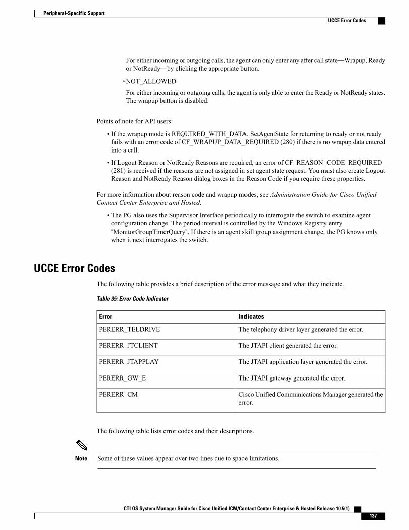
For either incoming or outgoing calls, the agent can only enter any after call state—Wrapup, Readyor NotReady—by clicking the appropriate button.
◦NOT_ALLOWED
For either incoming or outgoing calls, the agent is only able to enter the Ready or NotReady states.The wrapup button is disabled.
Points of note for API users:
• If the wrapup mode is REQUIRED_WITH_DATA, SetAgentState for returning to ready or not readyfails with an error code of CF_WRAPUP_DATA_REQUIRED (280) if there is no wrapup data enteredinto a call.
• If Logout Reason or NotReady Reasons are required, an error of CF_REASON_CODE_REQUIRED(281) is received if the reasons are not assigned in set agent state request. You must also create LogoutReason and NotReady Reason dialog boxes in the Reason Code if you require these properties.
For more information about reason code and wrapup modes, see Administration Guide for Cisco UnifiedContact Center Enterprise and Hosted.
• The PG also uses the Supervisor Interface periodically to interrogate the switch to examine agentconfiguration change. The period interval is controlled by the Windows Registry entry“MonitorGroupTimerQuery”. If there is an agent skill group assignment change, the PG knows onlywhen it next interrogates the switch.
UCCE Error CodesThe following table provides a brief description of the error message and what they indicate.
Table 35: Error Code Indicator
IndicatesError
The telephony driver layer generated the error.PERERR_TELDRIVE
The JTAPI client generated the error.PERERR_JTCLIENT
The JTAPI application layer generated the error.PERERR_JTAPPLAY
The JTAPI gateway generated the error.PERERR_GW_E
Cisco Unified CommunicationsManager generated theerror.
PERERR_CM
The following table lists error codes and their descriptions.
Some of these values appear over two lines due to space limitations.Note
CTI OS System Manager Guide for Cisco Unified ICM/Contact Center Enterprise & Hosted Release 10.5(1) 137
Peripheral-Specific SupportUCCE Error Codes
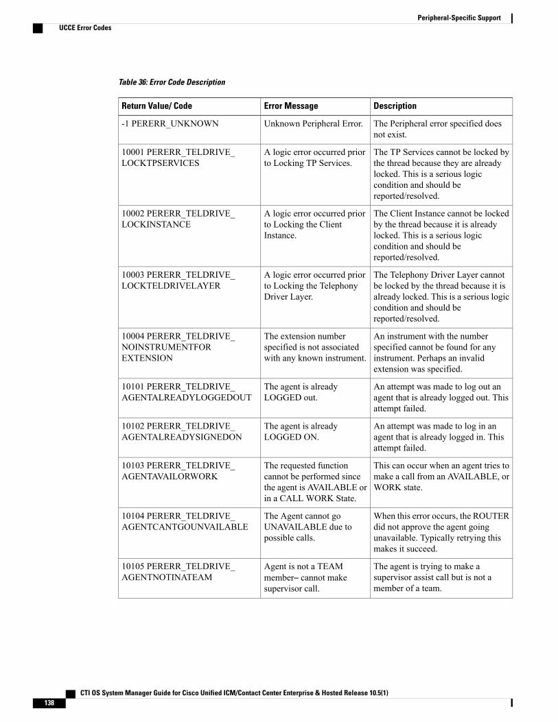
Table 36: Error Code Description
DescriptionError MessageReturn Value/ Code
The Peripheral error specified doesnot exist.
Unknown Peripheral Error.-1 PERERR_UNKNOWN
The TP Services cannot be locked bythe thread because they are alreadylocked. This is a serious logiccondition and should bereported/resolved.
A logic error occurred priorto Locking TP Services.
10001 PERERR_TELDRIVE_LOCKTPSERVICES
The Client Instance cannot be lockedby the thread because it is alreadylocked. This is a serious logiccondition and should bereported/resolved.
A logic error occurred priorto Locking the ClientInstance.
10002 PERERR_TELDRIVE_LOCKINSTANCE
The Telephony Driver Layer cannotbe locked by the thread because it isalready locked. This is a serious logiccondition and should bereported/resolved.
A logic error occurred priorto Locking the TelephonyDriver Layer.
10003 PERERR_TELDRIVE_LOCKTELDRIVELAYER
An instrument with the numberspecified cannot be found for anyinstrument. Perhaps an invalidextension was specified.
The extension numberspecified is not associatedwith any known instrument.
10004 PERERR_TELDRIVE_NOINSTRUMENTFOREXTENSION
An attempt was made to log out anagent that is already logged out. Thisattempt failed.
The agent is alreadyLOGGED out.
10101 PERERR_TELDRIVE_AGENTALREADYLOGGEDOUT
An attempt was made to log in anagent that is already logged in. Thisattempt failed.
The agent is alreadyLOGGED ON.
10102 PERERR_TELDRIVE_AGENTALREADYSIGNEDON
This can occur when an agent tries tomake a call from an AVAILABLE, orWORK state.
The requested functioncannot be performed sincethe agent is AVAILABLE orin a CALL WORK State.
10103 PERERR_TELDRIVE_AGENTAVAILORWORK
When this error occurs, the ROUTERdid not approve the agent goingunavailable. Typically retrying thismakes it succeed.
The Agent cannot goUNAVAILABLE due topossible calls.
10104 PERERR_TELDRIVE_AGENTCANTGOUNVAILABLE
The agent is trying to make asupervisor assist call but is not amember of a team.
Agent is not a TEAMmember– cannot makesupervisor call.
10105 PERERR_TELDRIVE_AGENTNOTINATEAM
CTI OS System Manager Guide for Cisco Unified ICM/Contact Center Enterprise & Hosted Release 10.5(1)138
Peripheral-Specific SupportUCCE Error Codes

DescriptionError MessageReturn Value/ Code
This error occurs when the agent istrying to make a call or consult callbut is currently RESERVED for anincoming call.
Agent is RESERVED –cannot make call.
10106 PERERR_TELDRIVE_AGENTRESERVED
The agent team specified in the agentobject cannot be found. This indicatesan internal error that should bereported and resolved.
Internal Logic Error –AgentTeam not found.
10107 PERERR_TELDRIVE_AGENTTEAMNOTFOUND
The routineValidateAgentPrevalentStateTransitiondetermined that the desired transitionwas illegal from the current state.
The state transition is invalidfrom the current state.
10108 PERERR_TELDRIVE_BADSTATETRANSITION
The call type that the call wasclassified into is not allowed for thedialed Number Plan used.
The agent is attempting tomake a call that is not validfor their defined call plan.
10109 PERERR_TELDRIVE_CALLTYPENOTVALIDFORDIALPLAN
Based upon transition rules, the agentcannot go READY. Examples: Youcannot go READY from TALKING.
Cannot transition to READYfrom current state.
10111 PERERR_TELDRIVE_CANTGOREADYFROMCURRENTSTATE
The agent must be NOT READY inorder to log out.
The agent cannot log outfrom the current state.
10112 PERERR_TELDRIVE_CANTLOGOUTFROMCURRENTSTATE
The routine run in objectThreadClearCall got an exception (notof type CiscoJTapiException) on a callto "drop".
JTAPI Gateway – Error onCLEAR CALL operation –Exception.
13042 PERERR_GW_E_THREADCLEARCALL_DROP_EXCEPTION
JTAPI Gateway – Error onCLEARCONNECTIONoperation – Unknownconnection ID.
13044 PERERR_GW_E_THREADCLEARCONNECTION_UNKNOWN_CONNECTION
The connection specified in the activeconnection is not in the TALKINGstate.
JTAPI Gateway – Error onCONFERENCE operation –ACTIVE connection not inproper state.
13045 PERERR_GW_E_THREADCONFERENCECALL_ACTIVE_CONN_NOT_TALKING
JTAPI Gateway – Error onCONFERENCE operation –ACTIVE connection notfound.
13046 PERERR_GW_E_THREADCONFERENCECALL_BAD_ACTIVE_CONNECTION
JTAPI Gateway – Error onCONFERENCE operation –HELD connection not found.
13047 PERERR_GW_E_THREADCONFERENCECALL_BAD_HELD_CONNECTION
CTI OS System Manager Guide for Cisco Unified ICM/Contact Center Enterprise & Hosted Release 10.5(1) 139
Peripheral-Specific SupportUCCE Error Codes
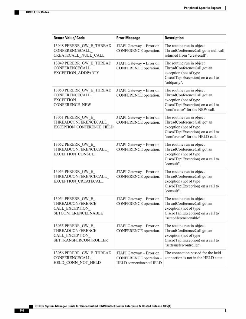
DescriptionError MessageReturn Value/ Code
The routine run in objectThreadConferenceCall got a null callreturned from "createcall".
JTAPI Gateway – Error onCONFERENCE operation.
13048 PERERR_GW_E_THREADCONFERENCECALL_CREATECALL_NULL_CALL
The routine run in objectThreadConferenceCall got anexception (not of typeCiscoJTapiException) on a call to"addparty".
JTAPI Gateway – Error onCONFERENCE operation.
13049 PERERR_GW_E_THREADCONFERENCECALL_EXCEPTION_ADDPARTY
The routine run in objectThreadConferenceCall got anexception (not of typeCiscoJTapiException) on a call to"conference" for the NEW call.
JTAPI Gateway – Error onCONFERENCE operation.
13050 PERERR_GW_E_THREADCONFERENCECALL_EXCEPTION_CONFERENCE_NEW
The routine run in objectThreadConferenceCall got anexception (not of typeCiscoJTapiException) on a call to"conference" for the HELD call.
JTAPI Gateway – Error onCONFERENCE operation.
13051 PERERR_GW_E_THREADCONFERENCECALL_EXCEPTION_CONFERENCE_HELD
The routine run in objectThreadConferenceCall got anexception (not of typeCiscoJTapiException) on a call to"consult".
JTAPI Gateway – Error onCONFERENCE operation.
13052 PERERR_GW_E_THREADCONFERENCECALL_EXCEPTION_CONSULT
The routine run in objectThreadConferenceCall got anexception (not of typeCiscoJTapiException) on a call to"consult".
JTAPI Gateway – Error onCONFERENCE operation.
13053 PERERR_GW_E_THREADCONFERENCECALL_EXCEPTION_CREATECALL
The routine run in objectThreadConferenceCall got anexception (not of typeCiscoJTapiException) on a call to"setconferenceenable".
JTAPI Gateway – Error onCONFERENCE operation.
13054 PERERR_GW_E_THREADCONFERENCECALL_EXCEPTION_SETCONFERENCEENABLE
The routine run in objectThreadConferenceCall got anexception (not of typeCiscoJTapiException) on a call to"settransfercontroller".
JTAPI Gateway – Error onCONFERENCE operation.
13055 PERERR_GW_E_THREADCONFERENCECALL_EXCEPTION_SETTRANSFERCONTROLLER
The connection passed for the heldconnection is not in the HELD state.
JTAPI Gateway – Error onCONFERENCE operation –HELDconnection notHELD
13056 PERERR_GW_E_THREADCONFERENCECALL_HELD_CONN_NOT_HELD
CTI OS System Manager Guide for Cisco Unified ICM/Contact Center Enterprise & Hosted Release 10.5(1)140
Peripheral-Specific SupportUCCE Error Codes
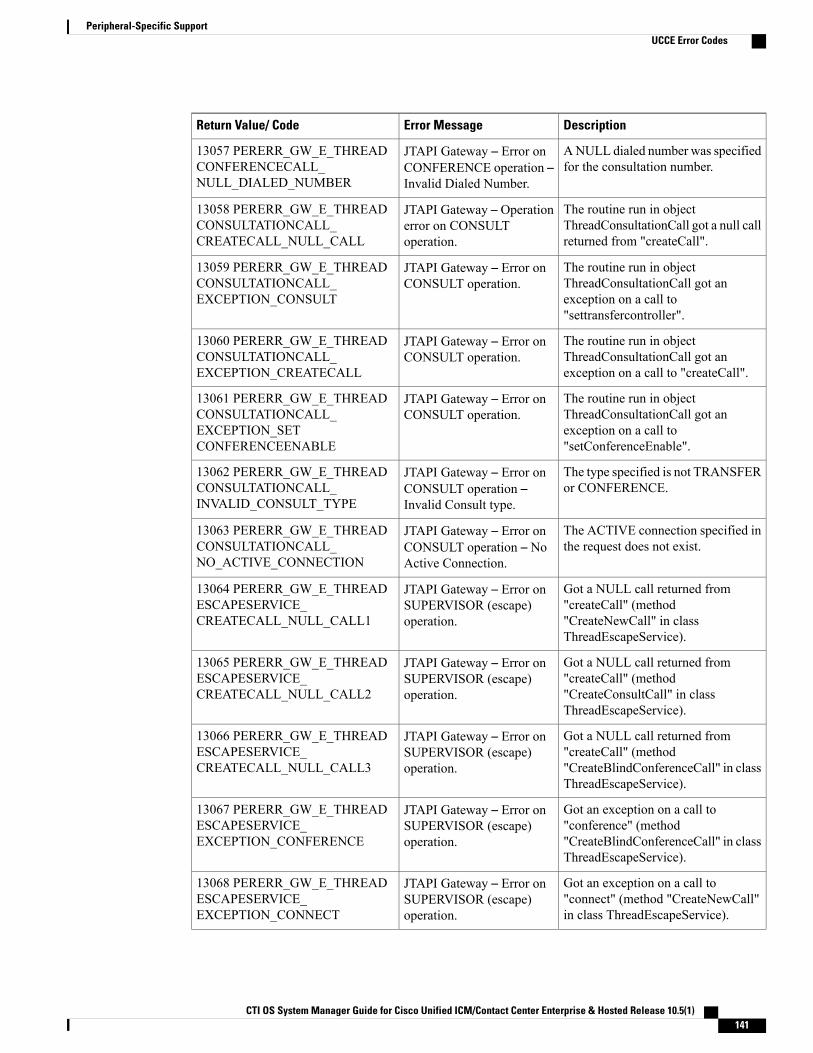
DescriptionError MessageReturn Value/ Code
ANULL dialed number was specifiedfor the consultation number.
JTAPI Gateway – Error onCONFERENCE operation –Invalid Dialed Number.
13057 PERERR_GW_E_THREADCONFERENCECALL_NULL_DIALED_NUMBER
The routine run in objectThreadConsultationCall got a null callreturned from "createCall".
JTAPI Gateway – Operationerror on CONSULToperation.
13058 PERERR_GW_E_THREADCONSULTATIONCALL_CREATECALL_NULL_CALL
The routine run in objectThreadConsultationCall got anexception on a call to"settransfercontroller".
JTAPI Gateway – Error onCONSULT operation.
13059 PERERR_GW_E_THREADCONSULTATIONCALL_EXCEPTION_CONSULT
The routine run in objectThreadConsultationCall got anexception on a call to "createCall".
JTAPI Gateway – Error onCONSULT operation.
13060 PERERR_GW_E_THREADCONSULTATIONCALL_EXCEPTION_CREATECALL
The routine run in objectThreadConsultationCall got anexception on a call to"setConferenceEnable".
JTAPI Gateway – Error onCONSULT operation.
13061 PERERR_GW_E_THREADCONSULTATIONCALL_EXCEPTION_SETCONFERENCEENABLE
The type specified is not TRANSFERor CONFERENCE.
JTAPI Gateway – Error onCONSULT operation –Invalid Consult type.
13062 PERERR_GW_E_THREADCONSULTATIONCALL_INVALID_CONSULT_TYPE
The ACTIVE connection specified inthe request does not exist.
JTAPI Gateway – Error onCONSULT operation – NoActive Connection.
13063 PERERR_GW_E_THREADCONSULTATIONCALL_NO_ACTIVE_CONNECTION
Got a NULL call returned from"createCall" (method"CreateNewCall" in classThreadEscapeService).
JTAPI Gateway – Error onSUPERVISOR (escape)operation.
13064 PERERR_GW_E_THREADESCAPESERVICE_CREATECALL_NULL_CALL1
Got a NULL call returned from"createCall" (method"CreateConsultCall" in classThreadEscapeService).
JTAPI Gateway – Error onSUPERVISOR (escape)operation.
13065 PERERR_GW_E_THREADESCAPESERVICE_CREATECALL_NULL_CALL2
Got a NULL call returned from"createCall" (method"CreateBlindConferenceCall" in classThreadEscapeService).
JTAPI Gateway – Error onSUPERVISOR (escape)operation.
13066 PERERR_GW_E_THREADESCAPESERVICE_CREATECALL_NULL_CALL3
Got an exception on a call to"conference" (method"CreateBlindConferenceCall" in classThreadEscapeService).
JTAPI Gateway – Error onSUPERVISOR (escape)operation.
13067 PERERR_GW_E_THREADESCAPESERVICE_EXCEPTION_CONFERENCE
Got an exception on a call to"connect" (method "CreateNewCall"in class ThreadEscapeService).
JTAPI Gateway – Error onSUPERVISOR (escape)operation.
13068 PERERR_GW_E_THREADESCAPESERVICE_EXCEPTION_CONNECT
CTI OS System Manager Guide for Cisco Unified ICM/Contact Center Enterprise & Hosted Release 10.5(1) 141
Peripheral-Specific SupportUCCE Error Codes
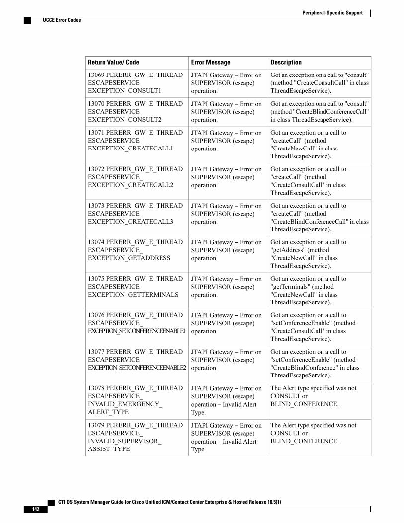
DescriptionError MessageReturn Value/ Code
Got an exception on a call to "consult"(method "CreateConsultCall" in classThreadEscapeService).
JTAPI Gateway – Error onSUPERVISOR (escape)operation.
13069 PERERR_GW_E_THREADESCAPESERVICE_EXCEPTION_CONSULT1
Got an exception on a call to "consult"(method "CreateBlindConferenceCall"in class ThreadEscapeService).
JTAPI Gateway – Error onSUPERVISOR (escape)operation.
13070 PERERR_GW_E_THREADESCAPESERVICE_EXCEPTION_CONSULT2
Got an exception on a call to"createCall" (method"CreateNewCall" in classThreadEscapeService).
JTAPI Gateway – Error onSUPERVISOR (escape)operation.
13071 PERERR_GW_E_THREADESCAPESERVICE_EXCEPTION_CREATECALL1
Got an exception on a call to"createCall" (method"CreateConsultCall" in classThreadEscapeService).
JTAPI Gateway – Error onSUPERVISOR (escape)operation.
13072 PERERR_GW_E_THREADESCAPESERVICE_EXCEPTION_CREATECALL2
Got an exception on a call to"createCall" (method"CreateBlindConferenceCall" in classThreadEscapeService).
JTAPI Gateway – Error onSUPERVISOR (escape)operation.
13073 PERERR_GW_E_THREADESCAPESERVICE_EXCEPTION_CREATECALL3
Got an exception on a call to"getAddress" (method"CreateNewCall" in classThreadEscapeService).
JTAPI Gateway – Error onSUPERVISOR (escape)operation.
13074 PERERR_GW_E_THREADESCAPESERVICE_EXCEPTION_GETADDRESS
Got an exception on a call to"getTerminals" (method"CreateNewCall" in classThreadEscapeService).
JTAPI Gateway – Error onSUPERVISOR (escape)operation.
13075 PERERR_GW_E_THREADESCAPESERVICE_EXCEPTION_GETTERMINALS
Got an exception on a call to"setConferenceEnable" (method"CreateConsultCall" in classThreadEscapeService).
JTAPI Gateway – Error onSUPERVISOR (escape)operation
13076 PERERR_GW_E_THREADESCAPESERVICE_EXCEPTION_SETCONFERENCEENABLE1
Got an exception on a call to"setConferenceEnable" (method"CreateBlindConference" in classThreadEscapeService).
JTAPI Gateway – Error onSUPERVISOR (escape)operation
13077 PERERR_GW_E_THREADESCAPESERVICE_EXCEPTION_SETCONFERENCEENABLE2
The Alert type specified was notCONSULT orBLIND_CONFERENCE.
JTAPI Gateway – Error onSUPERVISOR (escape)operation – Invalid AlertType.
13078 PERERR_GW_E_THREADESCAPESERVICE_INVALID_EMERGENCY_ALERT_TYPE
The Alert type specified was notCONSULT orBLIND_CONFERENCE.
JTAPI Gateway – Error onSUPERVISOR (escape)operation – Invalid AlertType.
13079 PERERR_GW_E_THREADESCAPESERVICE_INVALID_SUPERVISOR_ASSIST_TYPE
CTI OS System Manager Guide for Cisco Unified ICM/Contact Center Enterprise & Hosted Release 10.5(1)142
Peripheral-Specific SupportUCCE Error Codes
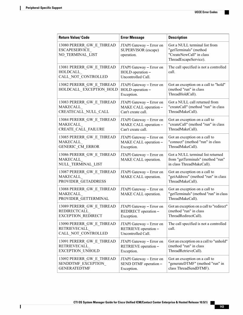
DescriptionError MessageReturn Value/ Code
Got a NULL terminal list from"getTerminals" (method"CreateNewCall" in classThreadEscapeService).
JTAPI Gateway – Error onSUPERVISOR (escape)operation.
13080 PERERR_GW_E_THREADESCAPESERVICE_NO_TERMINAL_LIST
The call specified is not a controlledcall.
JTAPI Gateway – Error onHOLD operation –Uncontrolled Call.
13081 PERERR_GW_E_THREADHOLDCALL_CALL_NOT_CONTROLLED
Got an exception on a call to "hold"(method "run" in classThreadHoldCall).
JTAPI Gateway – Error onHOLD operation –Exception.
13082 PERERR_GW_E_THREADHOLDCALL_EXCEPTION_HOLD
Got a NULL call returned from"createCall" (method "run" in classThreadMakeCall).
JTAPI Gateway – Error onMAKE CALL operation –Can't create call.
13083 PERERR_GW_E_THREADMAKECALL_CREATECALL_NULL_CALL
Got an exception on a call to"createCall" (method "run" in classThreadMakeCall).
JTAPI Gateway – Error onMAKE CALL operation –Can't create call.
13084 PERERR_GW_E_THREADMAKECALL_CREATE_CALL_FAILURE
Got an exception on a call to"connect" (method "run" in classThreadMakeCall).
JTAPI Gateway – Error onMAKE CALL operation –Exception.
13085 PERERR_GW_E_THREADMAKECALL_GENERIC_CM_ERROR
Got a NULL terminal list returnedfrom "getTerminals" (method "run"in class ThreadMakeCall).
JTAPI Gateway – Error onMAKE CALL operation.
13086 PERERR_GW_E_THREADMAKECALL_NULL_TERMINAL_LIST
Got an exception on a call to"getAddress" (method "run" in classThreadMakeCall).
JTAPI Gateway – Error onMAKE CALL operation.
13087 PERERR_GW_E_THREADMAKECALL_PROVIDER_GETADDRESS
Got an exception on a call to"getTerminals" (method "run" in classThreadMakeCall).
JTAPI Gateway – Error onMAKE CALL operation.
13088 PERERR_GW_E_THREADMAKECALL_PROVIDER_GETTERMINAL
Got an exception on a call to "redirect"(method "run" in classThreadRedirectCall).
JTAPI Gateway – Error onREDIRECT operation –Exception.
13089 PERERR_GW_E_THREADREDIRECTCALL_EXCEPTION_REDIRECT
The call specified is not a controlledcall.
JTAPI Gateway – Error onRETRIEVE operation –Uncontrolled Call.
13090 PERERR_GW_E_THREADRETRIEVECALL_CALL_NOT_CONTROLLED
Got an exception on a call to "unhold"(method "run" in classThreadRetrieveCall).
JTAPI Gateway – Error onRETRIEVE operation –Exception.
13091 PERERR_GW_E_THREADRETRIEVECALL_EXCEPTION_UNHOLD
Got an exception on a call to"generateDTMF" (method "run" inclass ThreadSendDTMF).
JTAPI Gateway – Error onSEND DTMF operation –Exception.
13092 PERERR_GW_E_THREADSENDDTMF_EXCEPTION_GENERATEDTMF
CTI OS System Manager Guide for Cisco Unified ICM/Contact Center Enterprise & Hosted Release 10.5(1) 143
Peripheral-Specific SupportUCCE Error Codes
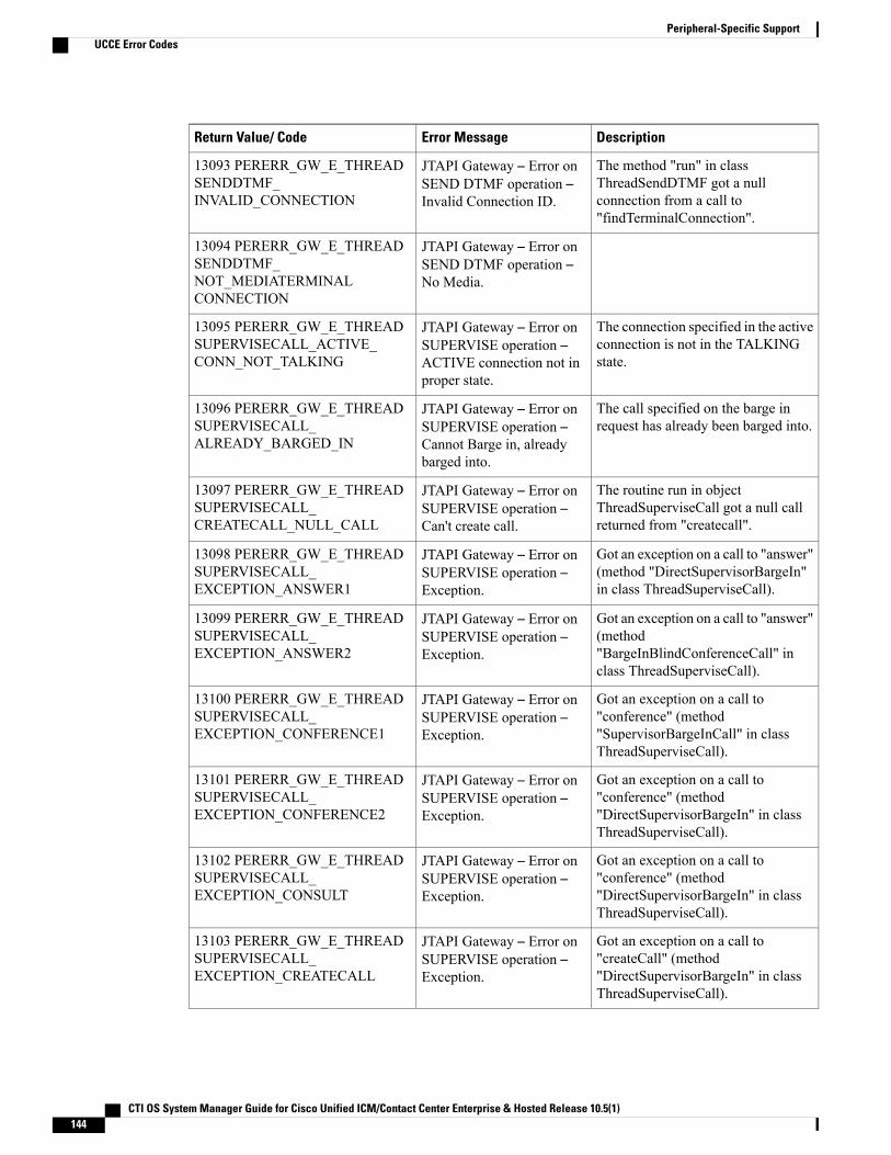
DescriptionError MessageReturn Value/ Code
The method "run" in classThreadSendDTMF got a nullconnection from a call to"findTerminalConnection".
JTAPI Gateway – Error onSEND DTMF operation –Invalid Connection ID.
13093 PERERR_GW_E_THREADSENDDTMF_INVALID_CONNECTION
JTAPI Gateway – Error onSEND DTMF operation –No Media.
13094 PERERR_GW_E_THREADSENDDTMF_NOT_MEDIATERMINALCONNECTION
The connection specified in the activeconnection is not in the TALKINGstate.
JTAPI Gateway – Error onSUPERVISE operation –ACTIVE connection not inproper state.
13095 PERERR_GW_E_THREADSUPERVISECALL_ACTIVE_CONN_NOT_TALKING
The call specified on the barge inrequest has already been barged into.
JTAPI Gateway – Error onSUPERVISE operation –Cannot Barge in, alreadybarged into.
13096 PERERR_GW_E_THREADSUPERVISECALL_ALREADY_BARGED_IN
The routine run in objectThreadSuperviseCall got a null callreturned from "createcall".
JTAPI Gateway – Error onSUPERVISE operation –Can't create call.
13097 PERERR_GW_E_THREADSUPERVISECALL_CREATECALL_NULL_CALL
Got an exception on a call to "answer"(method "DirectSupervisorBargeIn"in class ThreadSuperviseCall).
JTAPI Gateway – Error onSUPERVISE operation –Exception.
13098 PERERR_GW_E_THREADSUPERVISECALL_EXCEPTION_ANSWER1
Got an exception on a call to "answer"(method"BargeInBlindConferenceCall" inclass ThreadSuperviseCall).
JTAPI Gateway – Error onSUPERVISE operation –Exception.
13099 PERERR_GW_E_THREADSUPERVISECALL_EXCEPTION_ANSWER2
Got an exception on a call to"conference" (method"SupervisorBargeInCall" in classThreadSuperviseCall).
JTAPI Gateway – Error onSUPERVISE operation –Exception.
13100 PERERR_GW_E_THREADSUPERVISECALL_EXCEPTION_CONFERENCE1
Got an exception on a call to"conference" (method"DirectSupervisorBargeIn" in classThreadSuperviseCall).
JTAPI Gateway – Error onSUPERVISE operation –Exception.
13101 PERERR_GW_E_THREADSUPERVISECALL_EXCEPTION_CONFERENCE2
Got an exception on a call to"conference" (method"DirectSupervisorBargeIn" in classThreadSuperviseCall).
JTAPI Gateway – Error onSUPERVISE operation –Exception.
13102 PERERR_GW_E_THREADSUPERVISECALL_EXCEPTION_CONSULT
Got an exception on a call to"createCall" (method"DirectSupervisorBargeIn" in classThreadSuperviseCall).
JTAPI Gateway – Error onSUPERVISE operation –Exception.
13103 PERERR_GW_E_THREADSUPERVISECALL_EXCEPTION_CREATECALL
CTI OS System Manager Guide for Cisco Unified ICM/Contact Center Enterprise & Hosted Release 10.5(1)144
Peripheral-Specific SupportUCCE Error Codes

DescriptionError MessageReturn Value/ Code
Got an exception on a call to"disconnect" (method"DropSupervisorCall" in classThreadSuperviseCall).
JTAPI Gateway – Error onSUPERVISE operation –Exception.
13104 PERERR_GW_E_THREADSUPERVISECALL_EXCEPTION_DISCONNECT1
Got an exception on a call to"disconnect" (method "InterceptCall"in class ThreadSuperviseCall).
JTAPI Gateway – Error onSUPERVISE operation –Exception.
13105 PERERR_GW_E_THREADSUPERVISECALL_EXCEPTION_DISCONNECT2
Got an exception on a call to"disconnect" (method"DirectSupervisorBargeIn" in classThreadSuperviseCall).
JTAPI Gateway – Error onSUPERVISE operation –Exception.
13106 PERERR_GW_E_THREADSUPERVISECALL_EXCEPTION_SETCONFERENCEENABLE
The connection specified for theHELD call is not in the held state(method "BargInCall" classThreadSuperviseCall).
JTAPI Gateway – Error onSUPERVISE operation –HELD connection is notHELD.
13107 PERERR_GW_E_THREADSUPERVISECALL_HELD_CONN_NOT_HELD1
The connection specified for theHELD call is not in the held state(method "DirectSupervisorBargeIn"class ThreadSuperviseCall).
JTAPI Gateway – Error onSUPERVISE operation –HELD connection is notHELD.
13108 PERERR_GW_E_THREADSUPERVISECALL_HELD_CONN_NOT_HELD2
JTAPI Gateway – Error onSUPERVISE operation –Invalid action. The actionspecified was not CLEAR,BARGE_IN orINTERCEPT.
13109 PERERR_GW_E_THREADSUPERVISECALL_INVALID_ACTION
The connection specified in the activeconnection does not exist.
JTAPI Gateway – Error onSUPERVISE operation –NoACTIVE connection.
13110 PERERR_GW_E_THREADSUPERVISECALL_INVALID_ACTIVE_CONNECTION
The call ID in the agent object isinvalid (method "BargeInCall" classThreadSuperviseCall).
JTAPI Gateway – Error onSUPERVISE operation –Bad Call ID.
13111 PERERR_GW_E_THREADSUPERVISECALL_INVALID_AGENT_CALLID1
The call ID in the agent object isinvalid (method"DirectSupervisorBargeIn" classThreadSuperviseCall).
JTAPI Gateway – Error onSUPERVISE operation –Bad Call ID.
13112 PERERR_GW_E_THREADSUPERVISECALL_INVALID_AGENT_CALLID2
The connection ID in the agent objectis invalid (method "BargeInCall" classThreadSuperviseCall).
JTAPI Gateway – Error onSUPERVISE operation –Bad Connection ID.
13113 PERERR_GW_E_THREADSUPERVISECALL_INVALID_AGENT_CONNECTION1
The connection ID in the agent objectis invalid (method "InterceptCall"class ThreadSuperviseCall).
JTAPI Gateway – Error onSUPERVISE operation –Bad Connection ID.
13114 PERERR_GW_E_THREADSUPERVISECALL_INVALID_AGENT_CONNECTION2
CTI OS System Manager Guide for Cisco Unified ICM/Contact Center Enterprise & Hosted Release 10.5(1) 145
Peripheral-Specific SupportUCCE Error Codes
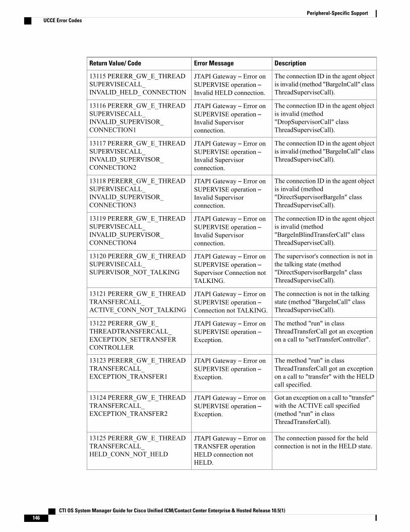
DescriptionError MessageReturn Value/ Code
The connection ID in the agent objectis invalid (method "BargeInCall" classThreadSuperviseCall).
JTAPI Gateway – Error onSUPERVISE operation –Invalid HELD connection.
13115 PERERR_GW_E_THREADSUPERVISECALL_INVALID_HELD_ CONNECTION
The connection ID in the agent objectis invalid (method"DropSupervisorCall" classThreadSuperviseCall).
JTAPI Gateway – Error onSUPERVISE operation –Invalid Supervisorconnection.
13116 PERERR_GW_E_THREADSUPERVISECALL_INVALID_SUPERVISOR_CONNECTION1
The connection ID in the agent objectis invalid (method "BargeInCall" classThreadSuperviseCall).
JTAPI Gateway – Error onSUPERVISE operation –Invalid Supervisorconnection.
13117 PERERR_GW_E_THREADSUPERVISECALL_INVALID_SUPERVISOR_CONNECTION2
The connection ID in the agent objectis invalid (method"DirectSupervisorBargeIn" classThreadSuperviseCall).
JTAPI Gateway – Error onSUPERVISE operation –Invalid Supervisorconnection.
13118 PERERR_GW_E_THREADSUPERVISECALL_INVALID_SUPERVISOR_CONNECTION3
The connection ID in the agent objectis invalid (method"BargeInBlindTransferCall" classThreadSuperviseCall).
JTAPI Gateway – Error onSUPERVISE operation –Invalid Supervisorconnection.
13119 PERERR_GW_E_THREADSUPERVISECALL_INVALID_SUPERVISOR_CONNECTION4
The supervisor's connection is not inthe talking state (method"DirectSupervisorBargeIn" classThreadSuperviseCall).
JTAPI Gateway – Error onSUPERVISE operation –Supervisor Connection notTALKING.
13120 PERERR_GW_E_THREADSUPERVISECALL_SUPERVISOR_NOT_TALKING
The connection is not in the talkingstate (method "BargeInCall" classThreadSuperviseCall).
JTAPI Gateway – Error onSUPERVISE operation –Connection not TALKING.
13121 PERERR_GW_E_THREADTRANSFERCALL_ACTIVE_CONN_NOT_TALKING
The method "run" in classThreadTransferCall got an exceptionon a call to "setTransferController".
JTAPI Gateway – Error onSUPERVISE operation –Exception.
13122 PERERR_GW_E_THREADTRANSFERCALL_EXCEPTION_SETTRANSFERCONTROLLER
The method "run" in classThreadTransferCall got an exceptionon a call to "transfer" with the HELDcall specified.
JTAPI Gateway – Error onSUPERVISE operation –Exception.
13123 PERERR_GW_E_THREADTRANSFERCALL_EXCEPTION_TRANSFER1
Got an exception on a call to "transfer"with the ACTIVE call specified(method "run" in classThreadTransferCall).
JTAPI Gateway – Error onSUPERVISE operation –Exception.
13124 PERERR_GW_E_THREADTRANSFERCALL_EXCEPTION_TRANSFER2
The connection passed for the heldconnection is not in the HELD state.
JTAPI Gateway – Error onTRANSFER operationHELD connection notHELD.
13125 PERERR_GW_E_THREADTRANSFERCALL_HELD_CONN_NOT_HELD
CTI OS System Manager Guide for Cisco Unified ICM/Contact Center Enterprise & Hosted Release 10.5(1)146
Peripheral-Specific SupportUCCE Error Codes
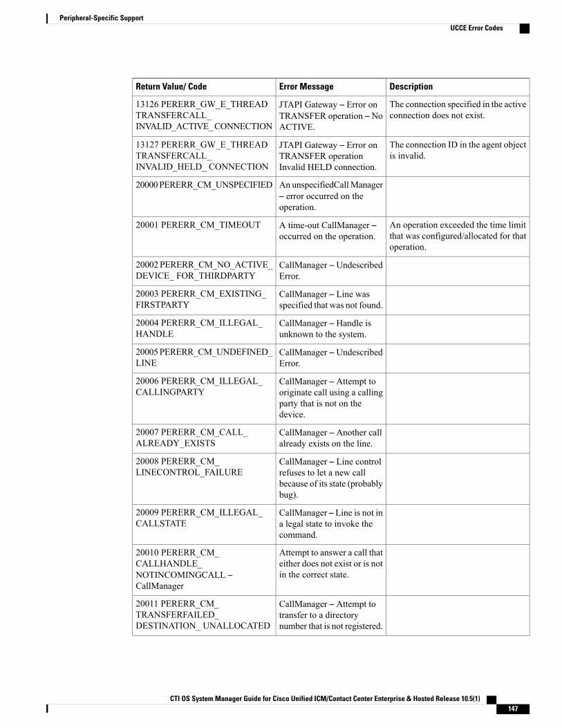
DescriptionError MessageReturn Value/ Code
The connection specified in the activeconnection does not exist.
JTAPI Gateway – Error onTRANSFER operation – NoACTIVE.
13126 PERERR_GW_E_THREADTRANSFERCALL_INVALID_ACTIVE_CONNECTION
The connection ID in the agent objectis invalid.
JTAPI Gateway – Error onTRANSFER operationInvalid HELD connection.
13127 PERERR_GW_E_THREADTRANSFERCALL_INVALID_HELD_ CONNECTION
An unspecifiedCallManager– error occurred on theoperation.
20000PERERR_CM_UNSPECIFIED
An operation exceeded the time limitthat was configured/allocated for thatoperation.
A time-out CallManager –occurred on the operation.
20001 PERERR_CM_TIMEOUT
CallManager – UndescribedError.
20002PERERR_CM_NO_ACTIVE_DEVICE_ FOR_THIRDPARTY
CallManager – Line wasspecified that was not found.
20003 PERERR_CM_EXISTING_FIRSTPARTY
CallManager – Handle isunknown to the system.
20004 PERERR_CM_ILLEGAL_HANDLE
CallManager – UndescribedError.
20005PERERR_CM_UNDEFINED_LINE
CallManager – Attempt tooriginate call using a callingparty that is not on thedevice.
20006 PERERR_CM_ILLEGAL_CALLINGPARTY
CallManager – Another callalready exists on the line.
20007 PERERR_CM_CALL_ALREADY_EXISTS
CallManager – Line controlrefuses to let a new callbecause of its state (probablybug).
20008 PERERR_CM_LINECONTROL_FAILURE
CallManager – Line is not ina legal state to invoke thecommand.
20009 PERERR_CM_ILLEGAL_CALLSTATE
Attempt to answer a call thateither does not exist or is notin the correct state.
20010 PERERR_CM_CALLHANDLE_NOTINCOMINGCALL –CallManager
CallManager – Attempt totransfer to a directorynumber that is not registered.
20011 PERERR_CM_TRANSFERFAILED_DESTINATION_ UNALLOCATED
CTI OS System Manager Guide for Cisco Unified ICM/Contact Center Enterprise & Hosted Release 10.5(1) 147
Peripheral-Specific SupportUCCE Error Codes

DescriptionError MessageReturn Value/ Code
CallManager – Attempt totransfer to a busy destination.
20013 PERERR_CM_TRANSFERFAILED_DESTINATION_BUSY
Probable cause is one of the call legswas hung up or disconnected from thefar end.
CallManager – Transferfailed.
20014 PERERR_CM_TRANSFERFAILED
CallManager – Hold wasrejected by line control orcall control.
20015PERERR_CM_HOLDFAILED
CallManager – Retrieve wasrejected by line control orcall control.
20017 PERERR_CM_RETRIEVEFAILED
CallManager – Error Nolonger used.
20018 PERERR_CM_DB_NO_MORE_DEVICES
CallManager – Error Nolonger used.
20020PERERR_CM_DB_ILLEGAL_DEVICE_TYPE
CallManager –Device querycontained an illegal devicetype.
20021 PERERR_CM_DB_ERROR
CallManager –Media cannotbe terminated by anapplication when the devicehas a physical phone (thephone always terminates themedia).
20022 PERERR_CM_CANNOT_TERMINATE_MEDIA_ON_PHONE
CallManager – Error nolonger used.
20025 PERERR_CM_UNKNOWN_GLOBAL_CALL_HANDLE
CallManager – Commandissued on a line that must beopen.
20026 PERERR_CM_DEVICE_NOT_OPEN
CallManager – UndescribedError.
20027PERERR_CM_ASSOCIATED_LINE_NOT_OPEN
CallManager – Redirectcommand was issued whenthe internal supportinginterface was not initialized.
20028 PERERR_CM_SSAPI_NOT_REGISTERED
CallManager – Attempt toredirect a call that does notexist or is no longer active.
20029 PERERR_CM_REDIRECT_CALL_DOES_NOT_EXIST
CTI OS System Manager Guide for Cisco Unified ICM/Contact Center Enterprise & Hosted Release 10.5(1)148
Peripheral-Specific SupportUCCE Error Codes
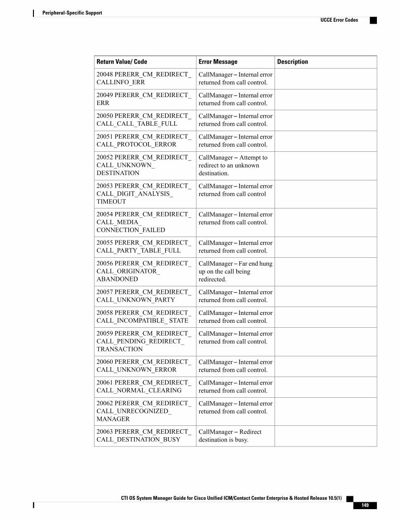
DescriptionError MessageReturn Value/ Code
CallManager – Internal errorreturned from call control.
20048 PERERR_CM_REDIRECT_CALLINFO_ERR
CallManager – Internal errorreturned from call control.
20049 PERERR_CM_REDIRECT_ERR
CallManager – Internal errorreturned from call control.
20050 PERERR_CM_REDIRECT_CALL_CALL_TABLE_FULL
CallManager – Internal errorreturned from call control.
20051 PERERR_CM_REDIRECT_CALL_PROTOCOL_ERROR
CallManager – Attempt toredirect to an unknowndestination.
20052 PERERR_CM_REDIRECT_CALL_UNKNOWN_DESTINATION
CallManager – Internal errorreturned from call control
20053 PERERR_CM_REDIRECT_CALL_DIGIT_ANALYSIS_TIMEOUT
CallManager – Internal errorreturned from call control.
20054 PERERR_CM_REDIRECT_CALL_MEDIA_CONNECTION_FAILED
CallManager – Internal errorreturned from call control.
20055 PERERR_CM_REDIRECT_CALL_PARTY_TABLE_FULL
CallManager – Far end hungup on the call beingredirected.
20056 PERERR_CM_REDIRECT_CALL_ORIGINATOR_ABANDONED
CallManager – Internal errorreturned from call control.
20057 PERERR_CM_REDIRECT_CALL_UNKNOWN_PARTY
CallManager – Internal errorreturned from call control.
20058 PERERR_CM_REDIRECT_CALL_INCOMPATIBLE_ STATE
CallManager – Internal errorreturned from call control.
20059 PERERR_CM_REDIRECT_CALL_PENDING_REDIRECT_TRANSACTION
CallManager – Internal errorreturned from call control.
20060 PERERR_CM_REDIRECT_CALL_UNKNOWN_ERROR
CallManager – Internal errorreturned from call control.
20061 PERERR_CM_REDIRECT_CALL_NORMAL_CLEARING
CallManager – Internal errorreturned from call control.
20062 PERERR_CM_REDIRECT_CALL_UNRECOGNIZED_MANAGER
CallManager – Redirectdestination is busy.
20063 PERERR_CM_REDIRECT_CALL_DESTINATION_BUSY
CTI OS System Manager Guide for Cisco Unified ICM/Contact Center Enterprise & Hosted Release 10.5(1) 149
Peripheral-Specific SupportUCCE Error Codes
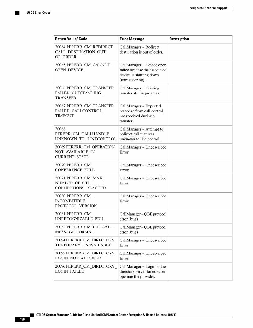
DescriptionError MessageReturn Value/ Code
CallManager – Redirectdestination is out of order.
20064 PERERR_CM_REDIRECT_CALL_DESTINATION_OUT_OF_ORDER
CallManager – Device openfailed because the associateddevice is shutting down(unregistering).
20065 PERERR_CM_CANNOT_OPEN_DEVICE
CallManager – Existingtransfer still in progress.
20066 PERERR_CM_TRANSFERFAILED_OUTSTANDING_TRANSFER
CallManager – Expectedresponse from call controlnot received during atransfer.
20067 PERERR_CM_TRANSFERFAILED_CALLCONTROL_TIMEOUT
CallManager – Attempt toredirect call that wasunknown to line control.
20068PERERR_CM_CALLHANDLE_UNKNOWN_TO_ LINECONTROL
CallManager – UndescribedError.
20069 PERERR_CM_OPERATION_NOT_AVAILABLE_IN_CURRENT_STATE
CallManager – UndescribedError.
20070 PERERR_CM_CONFERENCE_FULL
CallManager – UndescribedError.
20071 PERERR_CM_MAX_NUMBER_OF_CTI_CONNECTIONS_REACHED
CallManager – UndescribedError.
20080 PERERR_CM_INCOMPATIBLE_PROTOCOL_VERSION
CallManager –QBEprotocolerror (bug).
20081 PERERR_CM_UNRECOGNIZABLE_PDU
CallManager –QBEprotocolerror (bug).
20082 PERERR_CM_ILLEGAL_MESSAGE_FORMAT
CallManager – UndescribedError.
20094PERERR_CM_DIRECTORY_TEMPORARY_UNAVAILABLE
CallManager – UndescribedError.
20095PERERR_CM_DIRECTORY_LOGIN_NOT_ALLOWED
CallManager – Login to thedirectory server failed whenopening the provider.
20096PERERR_CM_DIRECTORY_LOGIN_FAILED
CTI OS System Manager Guide for Cisco Unified ICM/Contact Center Enterprise & Hosted Release 10.5(1)150
Peripheral-Specific SupportUCCE Error Codes

DescriptionError MessageReturn Value/ Code
CallManager – Attempt toissue a CTI command beforethe provider was open.
20097 PERERR_CM_PROVIDER_NOT_OPEN
CallManager – Attempt toreopen a provider.
20098 PERERR_CM_PROVIDER_ALREADY_OPEN
CallManager – Attempt toopen a provider before CTIinitialization completes.
20099 PERERR_CM_NOT_INITIALIZED
CallManager – Link failed toone of the call managers inthe cluster (network error).
20100 PERERR_CM_CLUSTER_LINK_FAILURE
CallManager – UndescribedError.
20101 PERERR_CM_LINE_INFO_DOES_NOT_EXIST
CallManager – UndescribedError.
20102 PERERR_CM_DIGIT_GENERATION_ALREADY_IN_PROGRESS
CallManager – UndescribedError.
20103 PERERR_CM_DIGIT_GENERATION_WRONG_CALL_HANDLE
CallManager – UndescribedError.
20104 PERERR_CM_DIGIT_GENERATION_WRONG_CALL_STATE
CallManager – UndescribedError.
20105 PERERR_CM_DIGIT_GENERATION_CALLSTATE_CHANGED
CallManager – UndescribedError.
20112 PERERR_CM_RETRIEVEFAILED_ACTIVE_CALL_ON_LINE
CallManager – UndescribedError.
20113PERERR_CM_INVALID_LINE_HANDLE
CallManager – UndescribedError.
20114 PERERR_CM_LINE_NOT_PRIMARY
CallManager – UndescribedError.
20115 PERERR_CM_CFWDALL_ALREADY_SET
CallManager – UndescribedError.
20116 PERERR_CM_CFWDALL_DESTN_INVALID
CallManager – UndescribedError.
20117 PERERR_CM_CFWDALL_ALREADY_OFF
CTI OS System Manager Guide for Cisco Unified ICM/Contact Center Enterprise & Hosted Release 10.5(1) 151
Peripheral-Specific SupportUCCE Error Codes
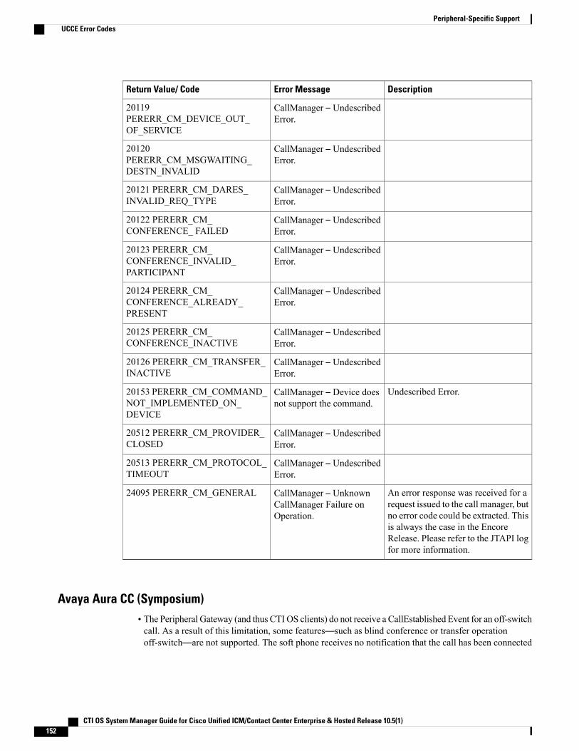
DescriptionError MessageReturn Value/ Code
CallManager – UndescribedError.
20119PERERR_CM_DEVICE_OUT_OF_SERVICE
CallManager – UndescribedError.
20120PERERR_CM_MSGWAITING_DESTN_INVALID
CallManager – UndescribedError.
20121 PERERR_CM_DARES_INVALID_REQ_TYPE
CallManager – UndescribedError.
20122 PERERR_CM_CONFERENCE_ FAILED
CallManager – UndescribedError.
20123 PERERR_CM_CONFERENCE_INVALID_PARTICIPANT
CallManager – UndescribedError.
20124 PERERR_CM_CONFERENCE_ALREADY_PRESENT
CallManager – UndescribedError.
20125 PERERR_CM_CONFERENCE_INACTIVE
CallManager – UndescribedError.
20126 PERERR_CM_TRANSFER_INACTIVE
Undescribed Error.CallManager – Device doesnot support the command.
20153 PERERR_CM_COMMAND_NOT_IMPLEMENTED_ON_DEVICE
CallManager – UndescribedError.
20512 PERERR_CM_PROVIDER_CLOSED
CallManager – UndescribedError.
20513 PERERR_CM_PROTOCOL_TIMEOUT
An error response was received for arequest issued to the call manager, butno error code could be extracted. Thisis always the case in the EncoreRelease. Please refer to the JTAPI logfor more information.
CallManager – UnknownCallManager Failure onOperation.
24095 PERERR_CM_GENERAL
Avaya Aura CC (Symposium)• The Peripheral Gateway (and thus CTI OS clients) do not receive a CallEstablished Event for an off-switchcall. As a result of this limitation, some features—such as blind conference or transfer operationoff-switch—are not supported. The soft phone receives no notification that the call has been connected
CTI OS System Manager Guide for Cisco Unified ICM/Contact Center Enterprise & Hosted Release 10.5(1)152
Peripheral-Specific SupportUCCE Error Codes
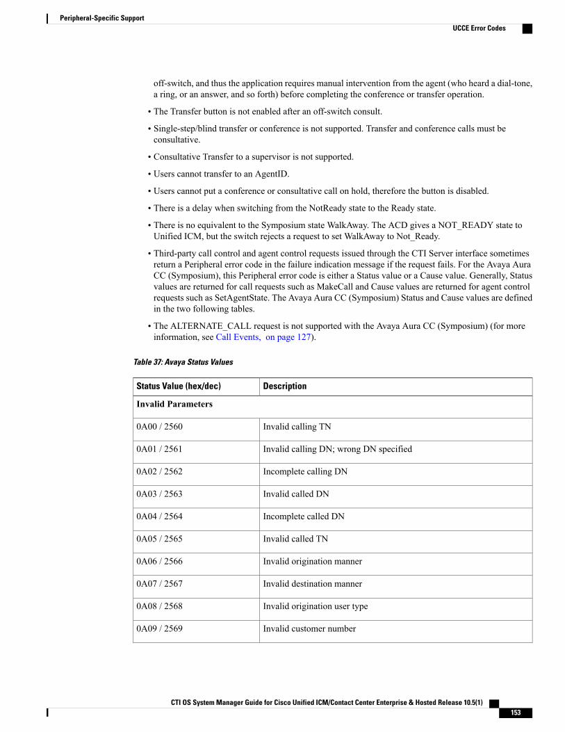
off-switch, and thus the application requires manual intervention from the agent (who heard a dial-tone,a ring, or an answer, and so forth) before completing the conference or transfer operation.
• The Transfer button is not enabled after an off-switch consult.
• Single-step/blind transfer or conference is not supported. Transfer and conference calls must beconsultative.
• Consultative Transfer to a supervisor is not supported.
• Users cannot transfer to an AgentID.
• Users cannot put a conference or consultative call on hold, therefore the button is disabled.
• There is a delay when switching from the NotReady state to the Ready state.
• There is no equivalent to the Symposium state WalkAway. The ACD gives a NOT_READY state toUnified ICM, but the switch rejects a request to set WalkAway to Not_Ready.
• Third-party call control and agent control requests issued through the CTI Server interface sometimesreturn a Peripheral error code in the failure indication message if the request fails. For the Avaya AuraCC (Symposium), this Peripheral error code is either a Status value or a Cause value. Generally, Statusvalues are returned for call requests such as MakeCall and Cause values are returned for agent controlrequests such as SetAgentState. The Avaya Aura CC (Symposium) Status and Cause values are definedin the two following tables.
• The ALTERNATE_CALL request is not supported with the Avaya Aura CC (Symposium) (for moreinformation, see Call Events, on page 127).
Table 37: Avaya Status Values
DescriptionStatus Value (hex/dec)
Invalid Parameters
Invalid calling TN0A00 / 2560
Invalid calling DN; wrong DN specified0A01 / 2561
Incomplete calling DN0A02 / 2562
Invalid called DN0A03 / 2563
Incomplete called DN0A04 / 2564
Invalid called TN0A05 / 2565
Invalid origination manner0A06 / 2566
Invalid destination manner0A07 / 2567
Invalid origination user type0A08 / 2568
Invalid customer number0A09 / 2569
CTI OS System Manager Guide for Cisco Unified ICM/Contact Center Enterprise & Hosted Release 10.5(1) 153
Peripheral-Specific SupportUCCE Error Codes
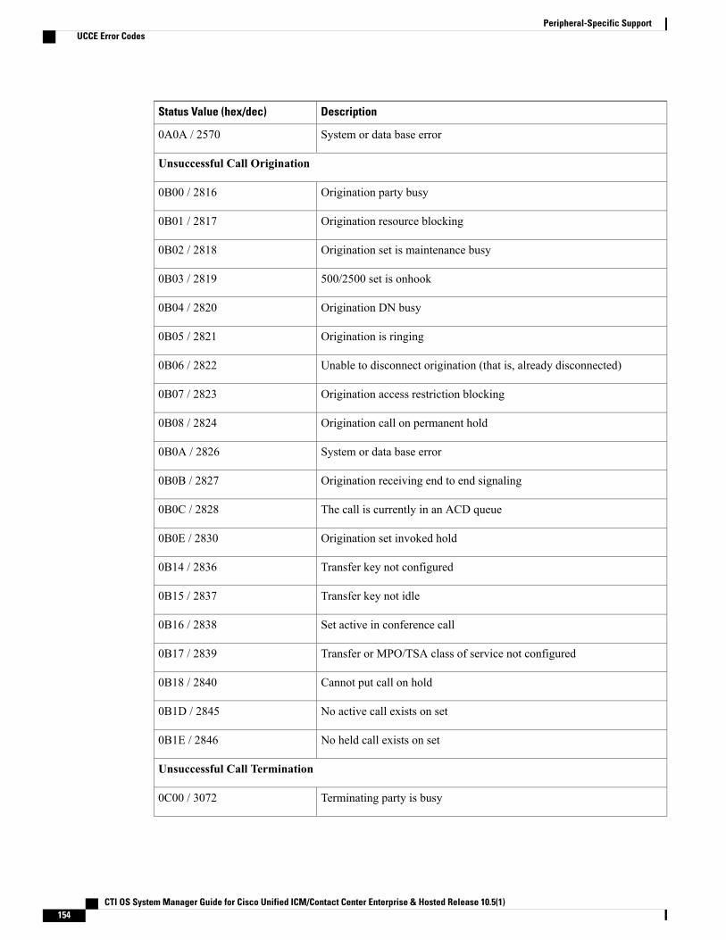
DescriptionStatus Value (hex/dec)
System or data base error0A0A / 2570
Unsuccessful Call Origination
Origination party busy0B00 / 2816
Origination resource blocking0B01 / 2817
Origination set is maintenance busy0B02 / 2818
500/2500 set is onhook0B03 / 2819
Origination DN busy0B04 / 2820
Origination is ringing0B05 / 2821
Unable to disconnect origination (that is, already disconnected)0B06 / 2822
Origination access restriction blocking0B07 / 2823
Origination call on permanent hold0B08 / 2824
System or data base error0B0A / 2826
Origination receiving end to end signaling0B0B / 2827
The call is currently in an ACD queue0B0C / 2828
Origination set invoked hold0B0E / 2830
Transfer key not configured0B14 / 2836
Transfer key not idle0B15 / 2837
Set active in conference call0B16 / 2838
Transfer or MPO/TSA class of service not configured0B17 / 2839
Cannot put call on hold0B18 / 2840
No active call exists on set0B1D / 2845
No held call exists on set0B1E / 2846
Unsuccessful Call Termination
Terminating party is busy0C00 / 3072
CTI OS System Manager Guide for Cisco Unified ICM/Contact Center Enterprise & Hosted Release 10.5(1)154
Peripheral-Specific SupportUCCE Error Codes

DescriptionStatus Value (hex/dec)
Destination resource blocking0C01 / 3073
Destination in invalid state0C02 / 3074
Destination access restriction blocking0C07 / 3079
System or database error0D0A / 3338
Network Interceptions
Unassigned number0C08 / 3080
No route to destination0C09 / 3081
No user responding0C0A / 3082
Number changed0C0B / 3083
Destination out of service0C0C / 3084
Invalid number format0C0D / 3085
No circuit available0C0E / 3086
Network out of order0C0F / 3087
Temporary failure0C10 / 3088
Equipment congestion0C11 / 3089
Network Interceptions with In-Band Information
Terminating party is busy0C19 / 3097
Unassigned number0C1A / 3098
No route to destination0C1B / 3099
No user responding0C1C / 3100
Number changed0C1D / 3101
Destination out of service0C1E / 3102
Invalid number format0C1F / 3103
No circuit available0C20 / 3104
CTI OS System Manager Guide for Cisco Unified ICM/Contact Center Enterprise & Hosted Release 10.5(1) 155
Peripheral-Specific SupportUCCE Error Codes
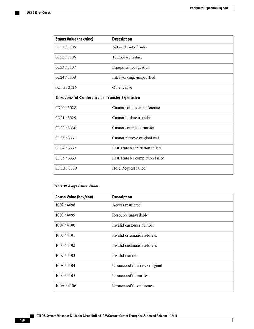
DescriptionStatus Value (hex/dec)
Network out of order0C21 / 3105
Temporary failure0C22 / 3106
Equipment congestion0C23 / 3107
Interworking, unspecified0C24 / 3108
Other cause0CFE / 3326
Unsuccessful Conference or Transfer Operation
Cannot complete conference0D00 / 3328
Cannot initiate transfer0D01 / 3329
Cannot complete transfer0D02 / 3330
Cannot retrieve original call0D03 / 3331
Fast Transfer initiation failed0D04 / 3332
Fast Transfer completion failed0D05 / 3333
Hold Request failed0D0B / 3339
Table 38: Avaya Cause Values
DescriptionCause Value (hex/dec)
Access restricted1002 / 4098
Resource unavailable1003 / 4099
Invalid customer number1004 / 4100
Invalid origination address1005 / 4101
Invalid destination address1006 / 4102
Invalid manner1007 / 4103
Unsuccessful retrieve original1008 / 4104
Unsuccessful transfer1009 / 4105
Unsuccessful conference100A / 4106
CTI OS System Manager Guide for Cisco Unified ICM/Contact Center Enterprise & Hosted Release 10.5(1)156
Peripheral-Specific SupportUCCE Error Codes
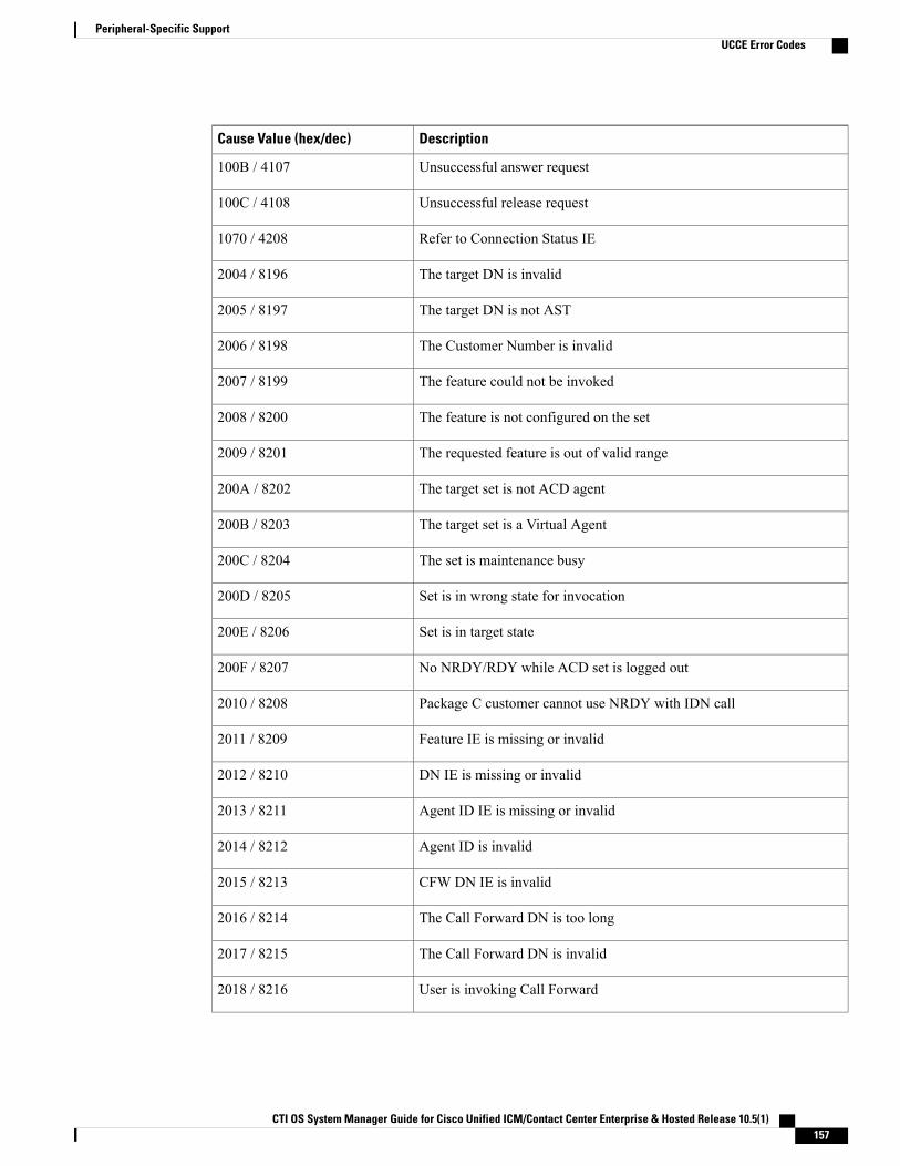
DescriptionCause Value (hex/dec)
Unsuccessful answer request100B / 4107
Unsuccessful release request100C / 4108
Refer to Connection Status IE1070 / 4208
The target DN is invalid2004 / 8196
The target DN is not AST2005 / 8197
The Customer Number is invalid2006 / 8198
The feature could not be invoked2007 / 8199
The feature is not configured on the set2008 / 8200
The requested feature is out of valid range2009 / 8201
The target set is not ACD agent200A / 8202
The target set is a Virtual Agent200B / 8203
The set is maintenance busy200C / 8204
Set is in wrong state for invocation200D / 8205
Set is in target state200E / 8206
No NRDY/RDY while ACD set is logged out200F / 8207
Package C customer cannot use NRDY with IDN call2010 / 8208
Feature IE is missing or invalid2011 / 8209
DN IE is missing or invalid2012 / 8210
Agent ID IE is missing or invalid2013 / 8211
Agent ID is invalid2014 / 8212
CFW DN IE is invalid2015 / 8213
The Call Forward DN is too long2016 / 8214
The Call Forward DN is invalid2017 / 8215
User is invoking Call Forward2018 / 8216
CTI OS System Manager Guide for Cisco Unified ICM/Contact Center Enterprise & Hosted Release 10.5(1) 157
Peripheral-Specific SupportUCCE Error Codes

DescriptionCause Value (hex/dec)
MSB/MSI not supported for 500/2500 sets2019 / 8217
500/2500 ACD agent already changed status201A / 8218
500/2500 ACD agent set is being rung201B / 8219
User is manually logging in 500 /2500 ACD set201C / 8220
Swap Feature in Symposium ACD
The Swap feature enables the agents to swap or alternate between customer calls and consult calls, both fromhardphones as well as softphones.
The Swap feature deploys a CTI toolbar with Unified ICM, offering most of the phone set functionalities.One of the most important functionalities is that it allows the agent to swap or alternate between primary andconsult calls during a Consultation Call.
The agent performing the transfer must carry out a swap, or alternate between the primary key (ACD or DN)and the secondary key of transfer. On the phone set, an agent can perform a swap by using the transfer orprimary key of the used line (ACD or DN).
The Swap feature is not supported when CTI OS is used with the Symposium.Note
Dependencies and Patches for Swap Feature Support in Softphones and Hardphones
The following patches are required for Swap feature support.
Symposium SCCS 5.0:
• SU 05
• SUS0501/02/03
• NN_SCCS_5.0_DP_050302_S (mandatory)
• NN_SCCS_5.0_DP_050301_S (optional)
NCCM 6.0:
• SU03
• SUS0301
• PEP_030130_RU
Nortel CS1000 Succession 4.0 or 4.5:
• MPLR20429
• MPLR21764
CTI OS System Manager Guide for Cisco Unified ICM/Contact Center Enterprise & Hosted Release 10.5(1)158
Peripheral-Specific SupportUCCE Error Codes
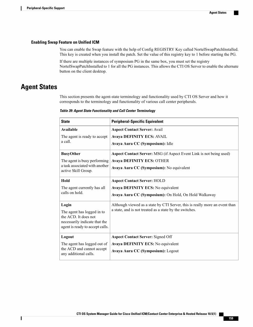
Enabling Swap Feature on Unified ICM
You can enable the Swap feature with the help of Config REGISTRY Key called NortelSwapPatchInstalled.This key is created when you install the patch. Set the value of this registry key to 1 before starting the PG.
If there are multiple instances of symposium PG in the same box, you must set the registryNortelSwapPatchInstalled to 1 for all the PG instances. This allows the CTI OS Server to enable the alternatebutton on the client desktop.
Agent StatesThis section presents the agent-state terminology and functionality used by CTI OS Server and how itcorresponds to the terminology and functionality of various call center peripherals.
Table 39: Agent State Functionality and Call Center Terminology
Peripheral-Specific EquivalentState
Aspect Contact Server: Avail
Avaya DEFINITY ECS: AVAIL
Avaya Aura CC (Symposium): Idle
Available
The agent is ready to accepta call.
Aspect Contact Server:MSG (if Aspect Event Link is not being used)
Avaya DEFINITY ECS: OTHER
Avaya Aura CC (Symposium): No equivalent
BusyOther
The agent is busy performinga task associated with anotheractive Skill Group.
Aspect Contact Server: HOLD
Avaya DEFINITY ECS: No equivalent
Avaya Aura CC (Symposium): On Hold, On Hold Walkaway
Hold
The agent currently has allcalls on hold.
Although viewed as a state by CTI Server, this is really more an event thana state, and is not treated as a state by the switches.
Login
The agent has logged in tothe ACD. It does notnecessarily indicate that theagent is ready to accept calls.
Aspect Contact Server: Signed Off
Avaya DEFINITY ECS: No equivalent
Avaya Aura CC (Symposium): Logout
Logout
The agent has logged out ofthe ACD and cannot acceptany additional calls.
CTI OS System Manager Guide for Cisco Unified ICM/Contact Center Enterprise & Hosted Release 10.5(1) 159
Peripheral-Specific SupportAgent States
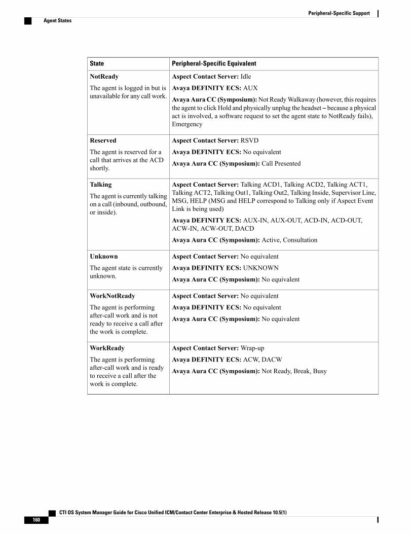
Peripheral-Specific EquivalentState
Aspect Contact Server: Idle
Avaya DEFINITY ECS: AUX
AvayaAuraCC (Symposium):Not ReadyWalkaway (however, this requiresthe agent to click Hold and physically unplug the headset – because a physicalact is involved, a software request to set the agent state to NotReady fails),Emergency
NotReady
The agent is logged in but isunavailable for any call work.
Aspect Contact Server: RSVD
Avaya DEFINITY ECS: No equivalent
Avaya Aura CC (Symposium): Call Presented
Reserved
The agent is reserved for acall that arrives at the ACDshortly.
Aspect Contact Server: Talking ACD1, Talking ACD2, Talking ACT1,Talking ACT2, Talking Out1, Talking Out2, Talking Inside, Supervisor Line,MSG, HELP (MSG and HELP correspond to Talking only if Aspect EventLink is being used)
Avaya DEFINITY ECS: AUX-IN, AUX-OUT, ACD-IN, ACD-OUT,ACW-IN, ACW-OUT, DACD
Avaya Aura CC (Symposium): Active, Consultation
Talking
The agent is currently talkingon a call (inbound, outbound,or inside).
Aspect Contact Server: No equivalent
Avaya DEFINITY ECS: UNKNOWN
Avaya Aura CC (Symposium): No equivalent
Unknown
The agent state is currentlyunknown.
Aspect Contact Server: No equivalent
Avaya DEFINITY ECS: No equivalent
Avaya Aura CC (Symposium): No equivalent
WorkNotReady
The agent is performingafter-call work and is notready to receive a call afterthe work is complete.
Aspect Contact Server:Wrap-up
Avaya DEFINITY ECS: ACW, DACW
Avaya Aura CC (Symposium): Not Ready, Break, Busy
WorkReady
The agent is performingafter-call work and is readyto receive a call after thework is complete.
CTI OS System Manager Guide for Cisco Unified ICM/Contact Center Enterprise & Hosted Release 10.5(1)160
Peripheral-Specific SupportAgent States
A P P E N D I X ATesting Ethernet Card for Silent Monitor
On a site where IP telephony is or will be deployed, the Unified CM and the IP Phones are normally configuredto use a Virtual Local Area Network (VLAN) such that voice is logically separated from data. Althoughboth traffic types are carried on the same physical channel they are transmitted on different VLANs, one forvoice and other for data. This configuration allows voice to be transmitted with higher priority than data.
In a call center that will use silent monitor you must connect the agent desktop system to the PC port on theback of the IP phone, such that voice packets reaching the phone can be collected by the silent monitorsubsystem to then forward to the supervisor workstation. The agent desktop system then uses one singlephysical channel to interact with two different VLANs.
The agent desktop system accesses the physical channel via an Ethernet Network Interface Controller (NIC).The NIC monitors the channel and collects Ethernet frames addressed to the agent's computer. The NIC thenruns a preprocessing step to extract IP packets from the Ethernet frames and deliver them to the TCP/IP stackon the operating system.
During internal testing Cisco identified that some Ethernet NIC card drivers available in the market are notcapable of pre-processing Ethernet frames that have an IP packet encapsulated in a VLAN frame; that is theNIC card driver discards the Ethernet frame altogether if the IP packet is encapsulated in an 802.1Q frame.Some vendors can provide a configuration setting that allows their NIC card driver to forward VLAN trafficto the TCP/IP stack.
If an agent desktop's NIC card driver discards VLAN traffic, then the silent monitor subsystem on thatdesktop cannot collect and forward voice packets to the supervisor workstation and silent monitor cannotfunction properly. Cisco developed a procedure to determine if a particular Ethernet NIC card driver workswith the CTI OS silent monitor. The procedure is described in the following sections.
• Test Procedure, page 161
Test ProcedureThe test involves sending sample VLAN packets to a Test Target NIC card and verifying that the packets arenot discarded by the pre-processing step but are passed onto the TCP/IP stack on the operating system at thecomputer hosting the NIC card.
CTI OS System Manager Guide for Cisco Unified ICM/Contact Center Enterprise & Hosted Release 10.5(1) 161
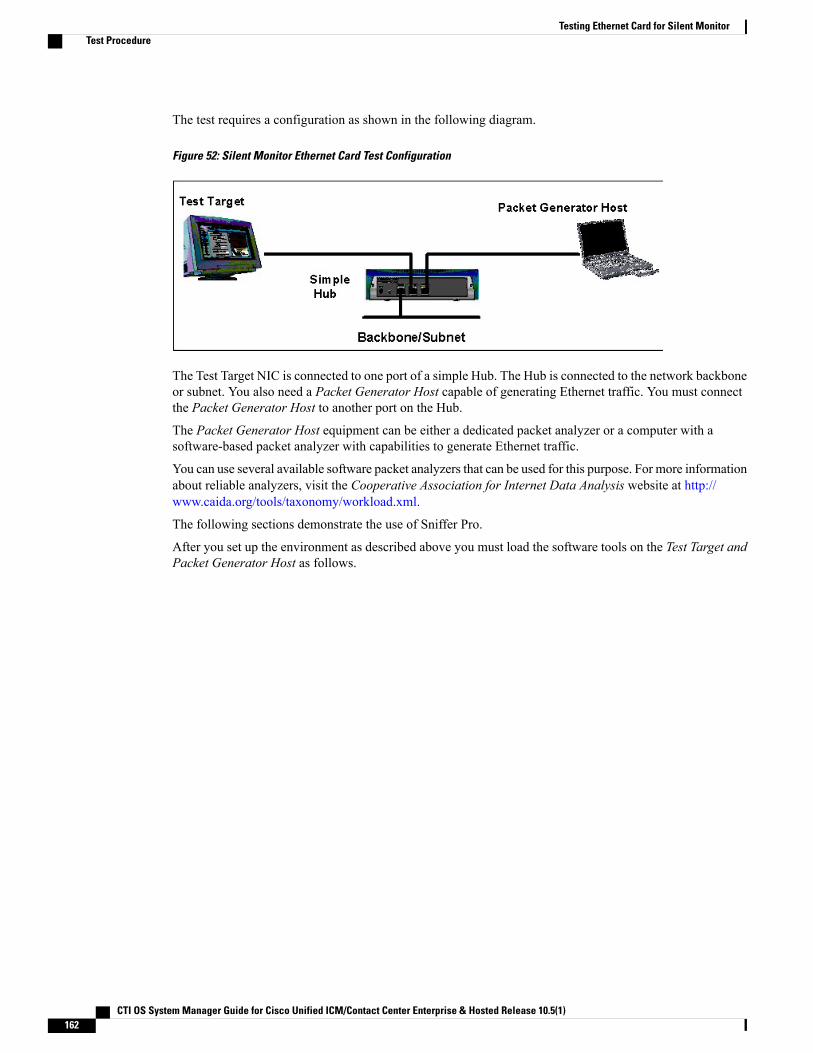
The test requires a configuration as shown in the following diagram.
Figure 52: Silent Monitor Ethernet Card Test Configuration
The Test Target NIC is connected to one port of a simple Hub. The Hub is connected to the network backboneor subnet. You also need a Packet Generator Host capable of generating Ethernet traffic. You must connectthe Packet Generator Host to another port on the Hub.
The Packet Generator Host equipment can be either a dedicated packet analyzer or a computer with asoftware-based packet analyzer with capabilities to generate Ethernet traffic.
You can use several available software packet analyzers that can be used for this purpose. For more informationabout reliable analyzers, visit the Cooperative Association for Internet Data Analysis website at http://www.caida.org/tools/taxonomy/workload.xml.
The following sections demonstrate the use of Sniffer Pro.
After you set up the environment as described above you must load the software tools on the Test Target andPacket Generator Host as follows.
CTI OS System Manager Guide for Cisco Unified ICM/Contact Center Enterprise & Hosted Release 10.5(1)162
Testing Ethernet Card for Silent MonitorTest Procedure
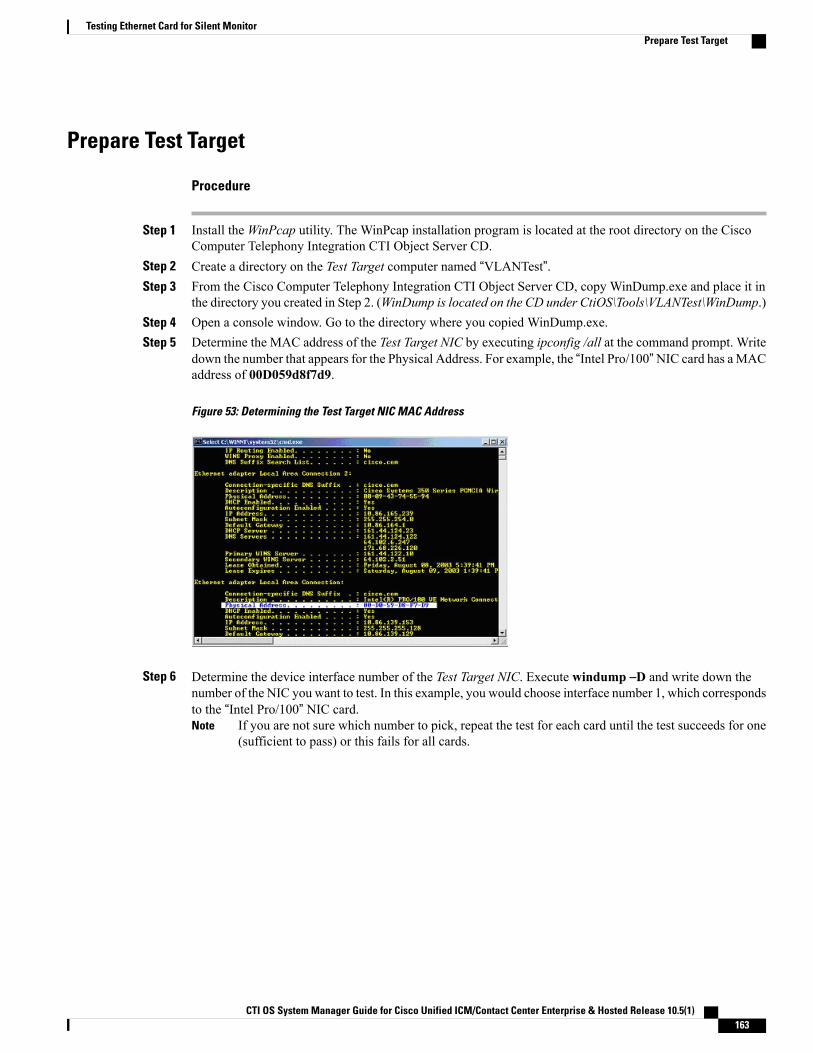
Prepare Test Target
Procedure
Step 1 Install theWinPcap utility. The WinPcap installation program is located at the root directory on the CiscoComputer Telephony Integration CTI Object Server CD.
Step 2 Create a directory on the Test Target computer named “VLANTest”.Step 3 From the Cisco Computer Telephony Integration CTI Object Server CD, copy WinDump.exe and place it in
the directory you created in Step 2. (WinDump is located on the CD under CtiOS\Tools\VLANTest\WinDump.)Step 4 Open a console window. Go to the directory where you copied WinDump.exe.Step 5 Determine the MAC address of the Test Target NIC by executing ipconfig /all at the command prompt. Write
down the number that appears for the Physical Address. For example, the “Intel Pro/100”NIC card has aMACaddress of 00D059d8f7d9.
Figure 53: Determining the Test Target NIC MAC Address
Step 6 Determine the device interface number of the Test Target NIC. Execute windump –D and write down thenumber of the NIC you want to test. In this example, you would choose interface number 1, which correspondsto the “Intel Pro/100” NIC card.
If you are not sure which number to pick, repeat the test for each card until the test succeeds for one(sufficient to pass) or this fails for all cards.
Note
CTI OS System Manager Guide for Cisco Unified ICM/Contact Center Enterprise & Hosted Release 10.5(1) 163
Testing Ethernet Card for Silent MonitorPrepare Test Target
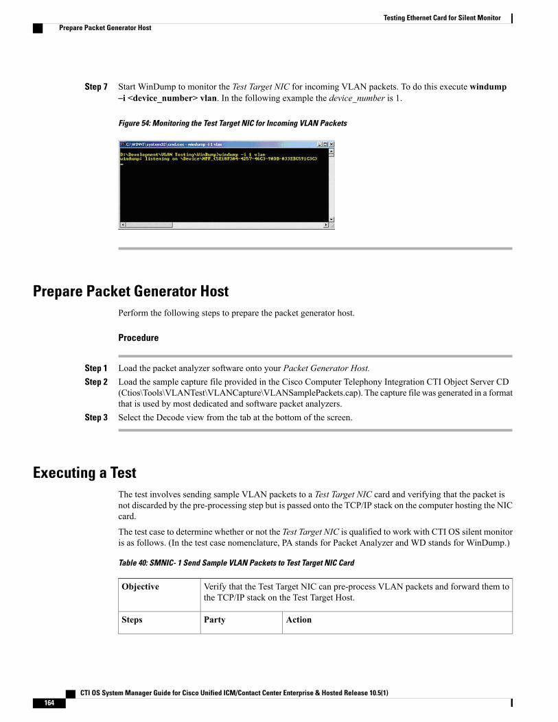
Step 7 Start WinDump to monitor the Test Target NIC for incoming VLAN packets. To do this execute windump–i <device_number> vlan. In the following example the device_number is 1.
Figure 54: Monitoring the Test Target NIC for Incoming VLAN Packets
Prepare Packet Generator HostPerform the following steps to prepare the packet generator host.
Procedure
Step 1 Load the packet analyzer software onto your Packet Generator Host.Step 2 Load the sample capture file provided in the Cisco Computer Telephony Integration CTI Object Server CD
(Ctios\Tools\VLANTest\VLANCapture\VLANSamplePackets.cap). The capture file was generated in a formatthat is used by most dedicated and software packet analyzers.
Step 3 Select the Decode view from the tab at the bottom of the screen.
Executing a TestThe test involves sending sample VLAN packets to a Test Target NIC card and verifying that the packet isnot discarded by the pre-processing step but is passed onto the TCP/IP stack on the computer hosting the NICcard.
The test case to determine whether or not the Test Target NIC is qualified to work with CTI OS silent monitoris as follows. (In the test case nomenclature, PA stands for Packet Analyzer and WD stands for WinDump.)
Table 40: SMNIC- 1 Send Sample VLAN Packets to Test Target NIC Card
Verify that the Test Target NIC can pre-process VLAN packets and forward them tothe TCP/IP stack on the Test Target Host.
Objective
ActionPartySteps
CTI OS System Manager Guide for Cisco Unified ICM/Contact Center Enterprise & Hosted Release 10.5(1)164
Testing Ethernet Card for Silent MonitorPrepare Packet Generator Host
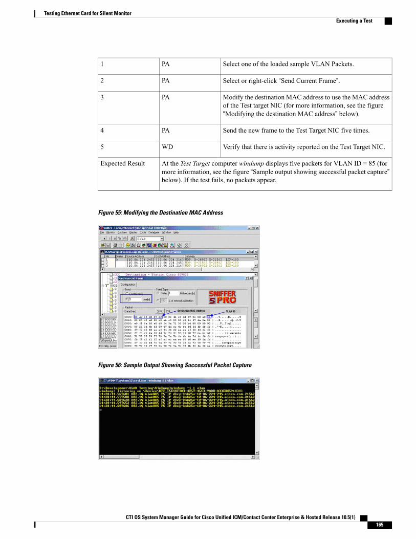
Select one of the loaded sample VLAN Packets.PA1
Select or right-click “Send Current Frame”.PA2
Modify the destination MAC address to use the MAC addressof the Test target NIC (for more information, see the figure“Modifying the destination MAC address” below).
PA3
Send the new frame to the Test Target NIC five times.PA4
Verify that there is activity reported on the Test Target NIC.WD5
At the Test Target computer windump displays five packets for VLAN ID = 85 (formore information, see the figure “Sample output showing successful packet capture”below). If the test fails, no packets appear.
Expected Result
Figure 55: Modifying the Destination MAC Address
Figure 56: Sample Output Showing Successful Packet Capture
CTI OS System Manager Guide for Cisco Unified ICM/Contact Center Enterprise & Hosted Release 10.5(1) 165
Testing Ethernet Card for Silent MonitorExecuting a Test

If the outcome of this test is successful, then your Test Target NIC works with the CTI OS silent monitor.Otherwise, contact your NIC card provider and ask what settings are necessary to allow your NIC card driverto forward all packets including VLAN packets to the TCP/IP stack on the computer so that your packetanalyzer tool can capture and display them. Then apply the appropriate adjustments and rerun this test procedure.
CTI OS System Manager Guide for Cisco Unified ICM/Contact Center Enterprise & Hosted Release 10.5(1)166
Testing Ethernet Card for Silent MonitorExecuting a Test