CTB-16K Assembly Manual - Light-O-Rama · Orange 3 Orange 3 Orange 3 Orange 1,000 Yellow 4 Yellow 4...
22
CTB-16KV6 Hobbyist Line Kit 40 Amp 16 Channel Light Controller Assembly Manual Version 2.03 February 15, 2007 Copyright © Light O Rama, Inc. 2006, 2007, 2008
Transcript of CTB-16K Assembly Manual - Light-O-Rama · Orange 3 Orange 3 Orange 3 Orange 1,000 Yellow 4 Yellow 4...
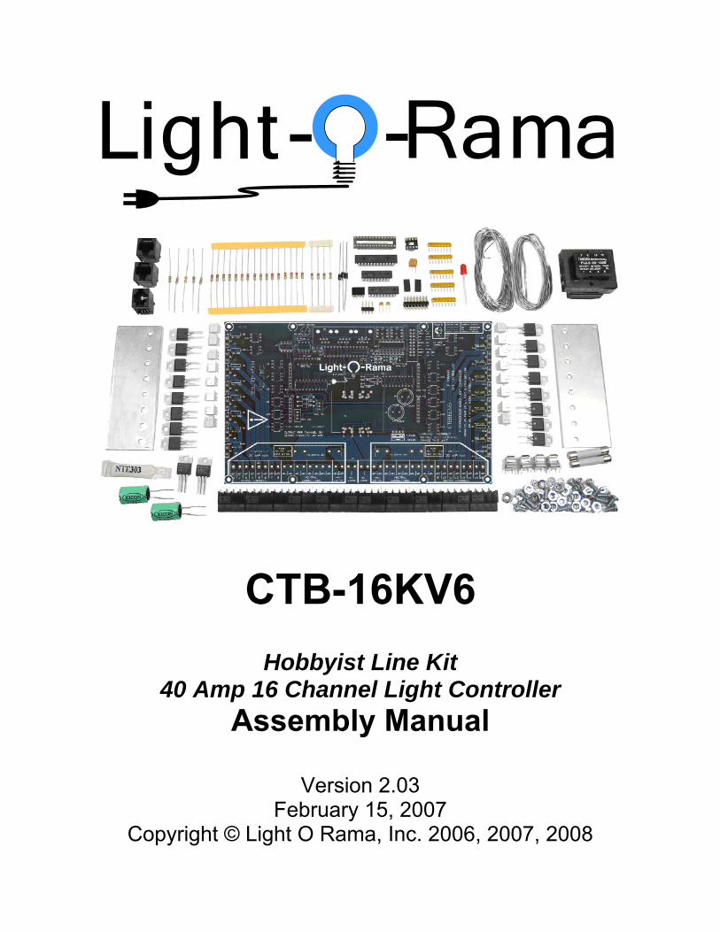
CTB-16KV6
Hobbyist Line Kit 40 Amp 16 Channel Light Controller
Assembly Manual
Version 2.03 February 15, 2007
Copyright © Light O Rama, Inc. 2006, 2007, 2008
CTB-16KV6 Assembly Manual
Page 2
Table of Contents
1 Introduction ...........................................................................................................................3 2 Required Tools......................................................................................................................3 3 Soldering ...............................................................................................................................4 4 Part Descriptions...................................................................................................................5
4.1 Diodes ...........................................................................................................................5 4.2 Resistors .......................................................................................................................5 4.3 Capacitors .....................................................................................................................6 4.4 DIP Integrated Circuits and Sockets .............................................................................7 4.5 Resistor Networks ........................................................................................................8 4.6 TO-220 Package Triac and Voltage Regulators............................................................8
5 Parts Lists .............................................................................................................................9 5.1 Standard Parts Kit .........................................................................................................9 5.2 Deluxe Add-on Parts Kit ..............................................................................................11
6 Completed CTB-16KV6 Deluxe w/Light Duty Heat Sinks ...................................................12 7 Assembly Instructions .........................................................................................................13
7.1 Pre-Assembly Notes....................................................................................................13 7.2 Assembly[ 1 of 7 ]: Resistors, Diodes, Ceramic Capacitors ........................................14 7.3 Assembly[ 2 of 7 ]: Resistor Networks, U3 IC, IC Sockets ..........................................15 7.4 Assembly[ 3 of 7 ]: Soldered in Integrated Circuits, Switches .....................................16 7.5 Assembly[ 4 of 7 ]: LED, Headers, Fuse holders ........................................................17 7.6 Assembly[ 5 of 7 ]: Voltage Regs, Jacks, Screw Strips, Electrolytic Caps, Resonator18 7.7 Assembly[ 6 of 7 ]: Triacs ............................................................................................19 7.8 Assembly[ 7 of 7 ]: Transformer, Socketed ICs, Fuses, Jumpers ...............................20 7.9 Post-Assembly Checks ...............................................................................................21 7.10 Installation of the (optional) Regular (High-power) Heat Sinks ...................................22
www.lightorama.com Light-O-Rama, Inc. Tel: (518) 539-9000 Fax: (518) 538-0067 [email protected]
CTB-16KV6 Assembly Manual
Page 3
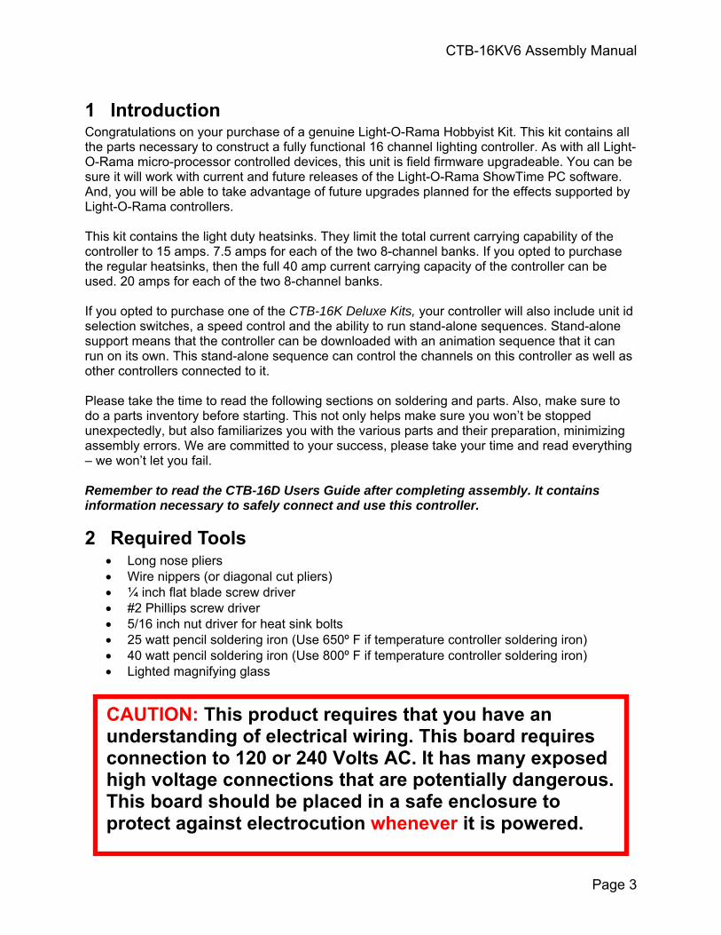
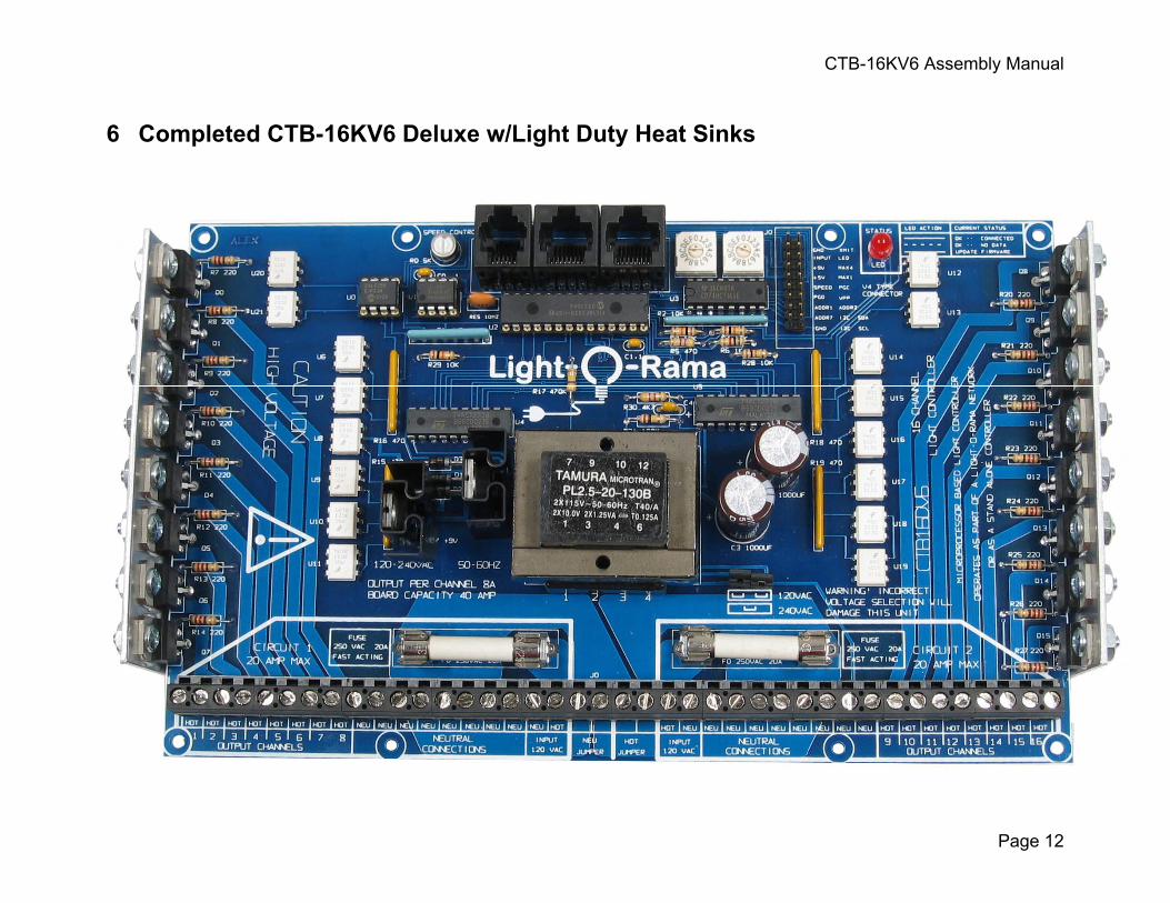
1 Introduction Congratulations on your purchase of a genuine Light-O-Rama Hobbyist Kit. This kit contains all the parts necessary to construct a fully functional 16 channel lighting controller. As with all Light-O-Rama micro-processor controlled devices, this unit is field firmware upgradeable. You can be sure it will work with current and future releases of the Light-O-Rama ShowTime PC software. And, you will be able to take advantage of future upgrades planned for the effects supported by Light-O-Rama controllers. This kit contains the light duty heatsinks. They limit the total current carrying capability of the controller to 15 amps. 7.5 amps for each of the two 8-channel banks. If you opted to purchase the regular heatsinks, then the full 40 amp current carrying capacity of the controller can be used. 20 amps for each of the two 8-channel banks. If you opted to purchase one of the CTB-16K Deluxe Kits, your controller will also include unit id selection switches, a speed control and the ability to run stand-alone sequences. Stand-alone support means that the controller can be downloaded with an animation sequence that it can run on its own. This stand-alone sequence can control the channels on this controller as well as other controllers connected to it. Please take the time to read the following sections on soldering and parts. Also, make sure to do a parts inventory before starting. This not only helps make sure you won’t be stopped unexpectedly, but also familiarizes you with the various parts and their preparation, minimizing assembly errors. We are committed to your success, please take your time and read everything – we won’t let you fail. Remember to read the CTB-16D Users Guide after completing assembly. It contains information necessary to safely connect and use this controller.
2 Required Tools • Long nose pliers • Wire nippers (or diagonal cut pliers) • ¼ inch flat blade screw driver • #2 Phillips screw driver • 5/16 inch nut driver for heat sink bolts • 25 watt pencil soldering iron (Use 650º F if temperature controller soldering iron) • 40 watt pencil soldering iron (Use 800º F if temperature controller soldering iron) • Lighted magnifying glass
CAUTION: This product requires that you have an
understanding of electrical wiring. This board requires connection to 120 or 240 Volts AC. It has many exposed high voltage connections that are potentially dangerous. This board should be placed in a safe enclosure to protect against electrocution whenever it is powered.
CTB-16KV6 Assembly Manual
Page 4
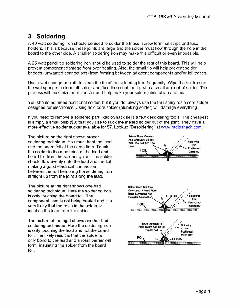
3 Soldering A 40 watt soldering iron should be used to solder the triacs, screw terminal strips and fuse holders. This is because these joints are large and the solder must flow through the hole in the board to the other side. A smaller soldering iron may make this difficult or even impossible. A 25 watt pencil tip soldering iron should be used to solder the rest of this board. This will help prevent component damage from over heating. Also, the small tip will help prevent solder bridges (unwanted connections) from forming between adjacent components and/or foil traces. Use a wet sponge or cloth to clean the tip of the soldering iron frequently. Wipe the hot iron on the wet sponge to clean off solder and flux, then coat the tip with a small amount of solder. This process will maximize heat transfer and help make your solder joints clean and neat. You should not need additional solder, but if you do, always use the thin shiny rosin core solder designed for electronics. Using acid core solder (plumbing solder) will damage everything. If you need to remove a soldered part, RadioShack sells a few desoldering tools. The cheapest is simply a small bulb ($3) that you use to suck the melted solder out of the joint. They have a more effective solder sucker available for $7. Lookup “Desoldering” at www.radioshack.com. The picture on the right shows proper soldering technique. You must heat the lead and the board foil at the same time. Touch the solder to the other side of the lead and board foil from the soldering iron. The solder should flow evenly onto the lead and the foil making a good electrical connection between them. Then bring the soldering iron straight up from the joint along the lead. The picture at the right shows one bad soldering technique. Here the soldering iron is only touching the board foil. The component lead is not being heated and it is very likely that the rosin in the solder will insulate the lead from the solder. The picture at the right shows another bad soldering technique. Here the soldering iron is only touching the lead and not the board foil. The likely result is that the solder will only bond to the lead and a rosin barrier will form, insulating the solder from the board foil.
CTB-16KV6 Assembly Manual
Page 5
4 Part Descriptions
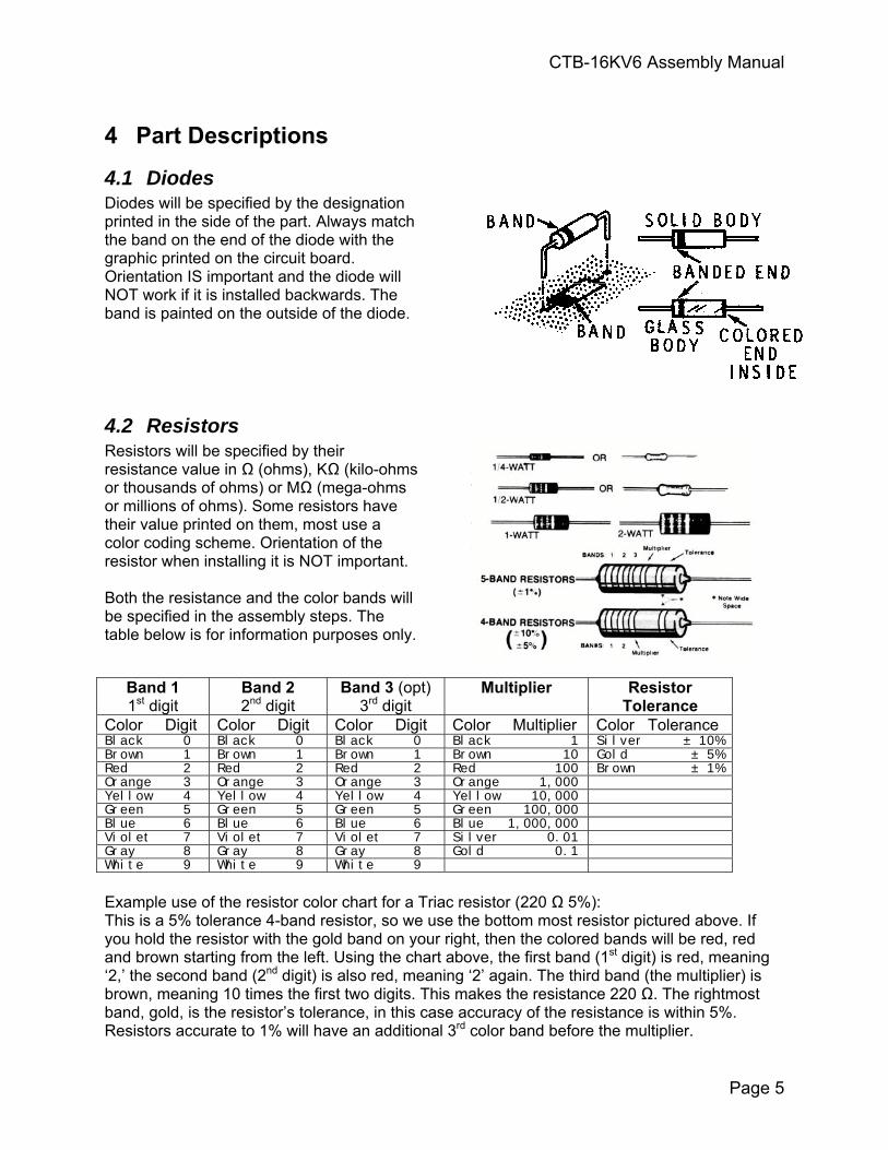
4.1 Diodes Diodes will be specified by the designation printed in the side of the part. Always match the band on the end of the diode with the graphic printed on the circuit board. Orientation IS important and the diode will NOT work if it is installed backwards. The band is painted on the outside of the diode.
4.2 Resistors Resistors will be specified by their resistance value in Ω (ohms), KΩ (kilo-ohms or thousands of ohms) or MΩ (mega-ohms or millions of ohms). Some resistors have their value printed on them, most use a color coding scheme. Orientation of the resistor when installing it is NOT important. Both the resistance and the color bands will be specified in the assembly steps. The table below is for information purposes only.
Band 1 1st digit
Band 2 2nd digit
Band 3 (opt) 3rd digit
Multiplier Resistor Tolerance
Color Digit Color Digit Color Digit Color Multiplier Color Tolerance Black 0 Black 0 Black 0 Black 1 Silver ± 10% Brown 1 Brown 1 Brown 1 Brown 10 Gold ± 5% Red 2 Red 2 Red 2 Red 100 Brown ± 1% Orange 3 Orange 3 Orange 3 Orange 1,000 Yellow 4 Yellow 4 Yellow 4 Yellow 10,000 Green 5 Green 5 Green 5 Green 100,000 Blue 6 Blue 6 Blue 6 Blue 1,000,000 Violet 7 Violet 7 Violet 7 Silver 0.01 Gray 8 Gray 8 Gray 8 Gold 0.1 White 9 White 9 White 9
Example use of the resistor color chart for a Triac resistor (220 Ω 5%): This is a 5% tolerance 4-band resistor, so we use the bottom most resistor pictured above. If you hold the resistor with the gold band on your right, then the colored bands will be red, red and brown starting from the left. Using the chart above, the first band (1st digit) is red, meaning ‘2,’ the second band (2nd digit) is also red, meaning ‘2’ again. The third band (the multiplier) is brown, meaning 10 times the first two digits. This makes the resistance 220 Ω. The rightmost band, gold, is the resistor’s tolerance, in this case accuracy of the resistance is within 5%. Resistors accurate to 1% will have an additional 3rd color band before the multiplier.
CTB-16KV6 Assembly Manual
Page 6
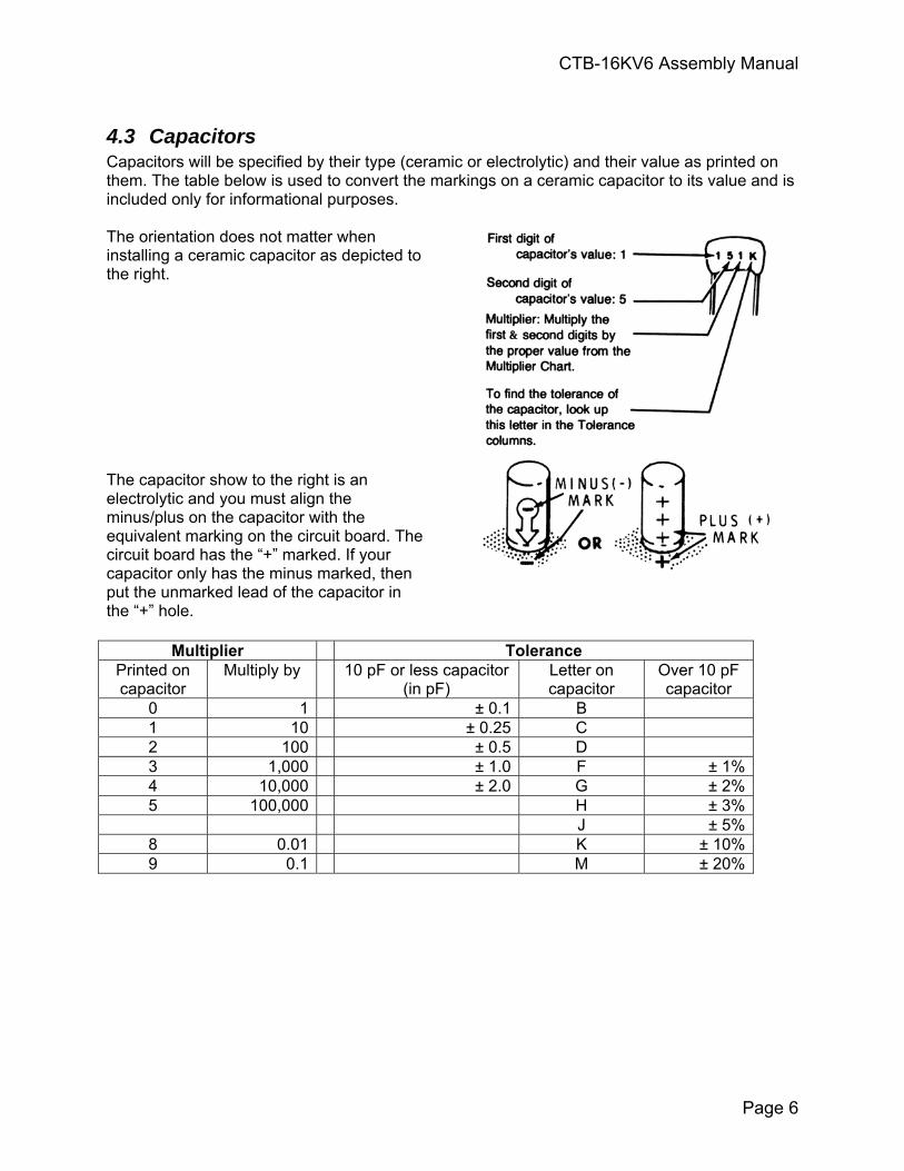
4.3 Capacitors Capacitors will be specified by their type (ceramic or electrolytic) and their value as printed on them. The table below is used to convert the markings on a ceramic capacitor to its value and is included only for informational purposes. The orientation does not matter when installing a ceramic capacitor as depicted to the right. The capacitor show to the right is an electrolytic and you must align the minus/plus on the capacitor with the equivalent marking on the circuit board. The circuit board has the “+” marked. If your capacitor only has the minus marked, then put the unmarked lead of the capacitor in the “+” hole.
Multiplier Tolerance Printed on capacitor
Multiply by 10 pF or less capacitor (in pF)
Letter on capacitor
Over 10 pF capacitor
0 1 ± 0.1 B 1 10 ± 0.25 C 2 100 ± 0.5 D 3 1,000 ± 1.0 F ± 1%4 10,000 ± 2.0 G ± 2%5 100,000 H ± 3% J ± 5%
8 0.01 K ± 10%9 0.1 M ± 20%
CTB-16KV6 Assembly Manual
Page 7
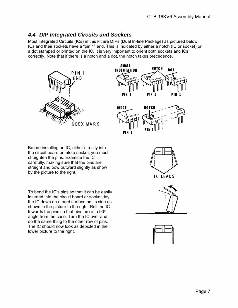
4.4 DIP Integrated Circuits and Sockets Most Integrated Circuits (ICs) in this kit are DIPs (Dual In-line Package) as pictured below. ICs and their sockets have a “pin 1” end. This is indicated by either a notch (IC or socket) or a dot stamped or printed on the IC. It is very important to orient both sockets and ICs correctly. Note that if there is a notch and a dot, the notch takes precedence.
Before installing an IC, either directly into the circuit board or into a socket, you must straighten the pins. Examine the IC carefully, making sure that the pins are straight and bow outward slightly as show by the picture to the right. To bend the IC’s pins so that it can be easily inserted into the circuit board or socket, lay the IC down on a hard surface on its side as shown in the picture to the right. Roll the IC towards the pins so that pins are at a 90º angle from the case. Turn the IC over and do the same thing to the other row of pins. The IC should now look as depicted in the lower picture to the right.
CTB-16KV6 Assembly Manual
Page 8
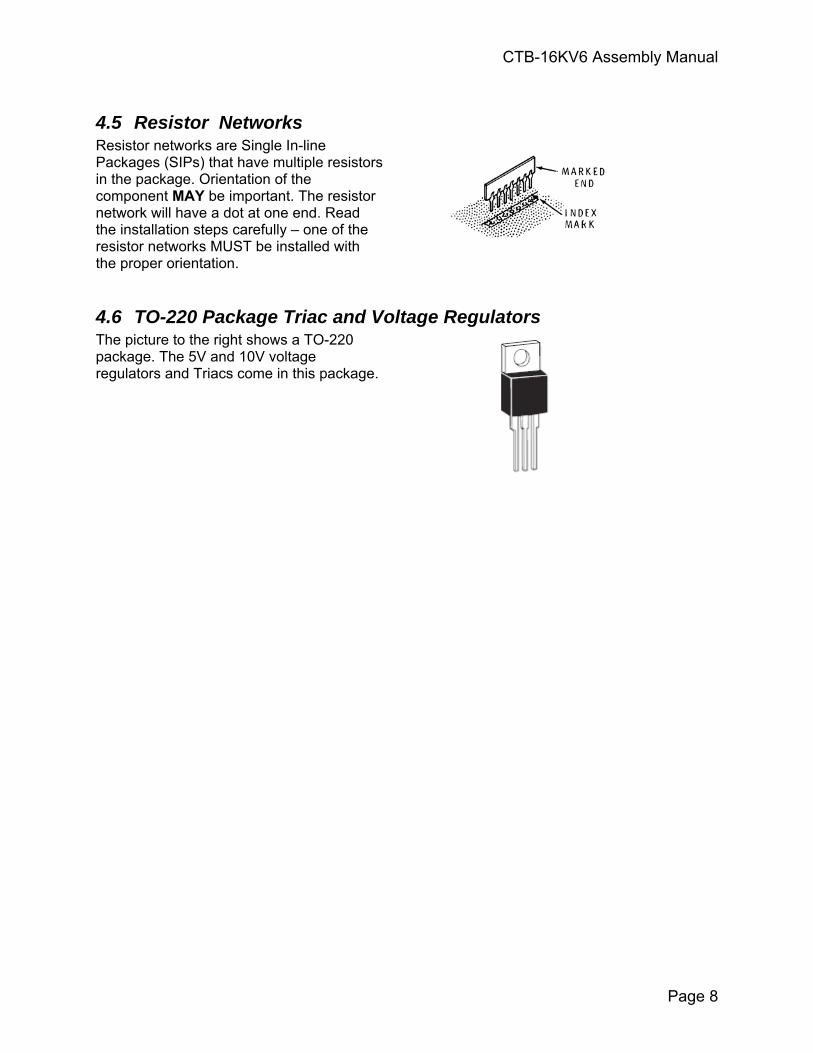
4.5 Resistor Networks Resistor networks are Single In-line Packages (SIPs) that have multiple resistors in the package. Orientation of the component MAY be important. The resistor network will have a dot at one end. Read the installation steps carefully – one of the resistor networks MUST be installed with the proper orientation.
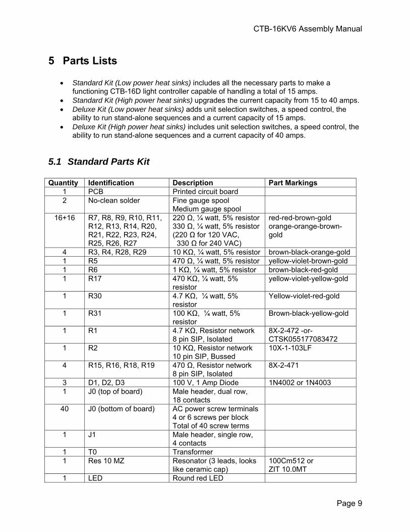
4.6 TO-220 Package Triac and Voltage Regulators The picture to the right shows a TO-220 package. The 5V and 10V voltage regulators and Triacs come in this package.
CTB-16KV6 Assembly Manual
Page 9
5 Parts Lists
• Standard Kit (Low power heat sinks) includes all the necessary parts to make a functioning CTB-16D light controller capable of handling a total of 15 amps.
• Standard Kit (High power heat sinks) upgrades the current capacity from 15 to 40 amps. • Deluxe Kit (Low power heat sinks) adds unit selection switches, a speed control, the
ability to run stand-alone sequences and a current capacity of 15 amps. • Deluxe Kit (High power heat sinks) includes unit selection switches, a speed control, the
ability to run stand-alone sequences and a current capacity of 40 amps.
5.1 Standard Parts Kit Quantity Identification Description Part Markings
1 PCB Printed circuit board 2 No-clean solder Fine gauge spool
Medium gauge spool
16+16 R7, R8, R9, R10, R11, R12, R13, R14, R20, R21, R22, R23, R24, R25, R26, R27
220 Ω, ¼ watt, 5% resistor 330 Ω, ¼ watt, 5% resistor (220 Ω for 120 VAC, 330 Ω for 240 VAC)
red-red-brown-gold orange-orange-brown-gold
4 R3, R4, R28, R29 10 KΩ, ¼ watt, 5% resistor brown-black-orange-gold 1 R5 470 Ω, ¼ watt, 5% resistor yellow-violet-brown-gold 1 R6 1 KΩ, ¼ watt, 5% resistor brown-black-red-gold 1 R17 470 KΩ, ¼ watt, 5%
resistor yellow-violet-yellow-gold
1 R30 4.7 KΩ, ¼ watt, 5% resistor
Yellow-violet-red-gold
1 R31 100 KΩ, ¼ watt, 5% resistor
Brown-black-yellow-gold
1 R1 4.7 KΩ, Resistor network 8 pin SIP, Isolated
8X-2-472 -or- CTSK055177083472
1 R2 10 KΩ, Resistor network 10 pin SIP, Bussed
10X-1-103LF
4 R15, R16, R18, R19 470 Ω, Resistor network 8 pin SIP, Isolated
8X-2-471
3 D1, D2, D3 100 V, 1 Amp Diode 1N4002 or 1N4003 1 J0 (top of board) Male header, dual row,
18 contacts
40 J0 (bottom of board) AC power screw terminals 4 or 6 screws per block Total of 40 screw terms
1 J1 Male header, single row, 4 contacts
1 T0 Transformer 1 Res 10 MZ Resonator (3 leads, looks
like ceramic cap) 100Cm512 or ZIT 10.0MT
1 LED Round red LED
CTB-16KV6 Assembly Manual
Page 10
16 Q0, Q1, Q2, Q3, Q4, Q5, Q6, Q7, Q8, Q9, Q10, Q11, Q12, Q13, Q14, Q15
Triac, 16A, 600V, TO-220 case, snubberless, isolated – center lead pre-bent for insertion into the circuit board
BTA16-600BW
1 Q16 5V, 1.5A Voltage regulator TO-220 case – center lead is not bent like triacs
TL7805C –or- LM340TS7805
1 Q17 10V, 1.5A, Voltage regulator, TO-220 case
UA7810C
1 C0 .1uF 50V 10% Ceramic capacitor
104
1 C1 1uF 50V 10% Ceramic capacitor
105Z
2 C2, C3 1000uF 35V Electrolytic capacitor
1000 uF 35v
1 C4 .47 uF 50V 10% Ceramic capacitor
474Z
1 U1 socket 8 pin IC socket 1 U1 485 skewlimited driver
8 pin DIP MAX3082EEPA or ISL81487LIP
1 U2 socket 28 pin IC socket 1 U2 Micro-processor PIC18F2620 1 U3 8 bit shift register
16 pin DIP 74HCT165
2 U4, U5 8 bit flip-flop 20 pin DIP
74ACT273
16 U6, U7, U8, U9, U10, U11, U12, U13, U14, U15, U16, U17, U18, U19, U20, U21
400V Triac opto-isolator 6 pin DIP
MOC3023
2 sets F0a, F0b, F1a, F1b Fuse clips 2 RJ1, RJ2 Female RJ45 connector
8 contacts
1 RJ3 Female RJ12 connector 6 contacts
2 Fuse0, Fuse1 15A, 250V, Ceramic Fast acting
3 Jumper1, Jumper2, Jumper3
Small black plastic tabs with copper inside that are used on J0 and J1
2 Light duty heat sink triac heat sink
Flat metal with 8 triac screw holes – use as an installation guide
1 Thermal compound Heat transfer paste if using light duty heat sinks
Packet tube
16 Screw/Washer/Nut set Triac to heat sink screw, washer & nut sets
2 Voltage regulator heat sink
Black metal for TO-220 voltage regulators
Approximately ¾” x ¾” x ½”
CTB-16KV6 Assembly Manual
Page 11
5.2 Deluxe Add-on Parts Kit Quantity Board Identification Description Part Markings
1 U0 socket 8 pin IC socket 1 U0 Serial EEPROM 256K
8 pin DIP 24LC256I/P
1 R0 5 KΩ Potentiometer 2 S0, S1 Rotary switch 0,1,2,3,…F
CTB-16KV6 Assembly Manual
Page 12
6 Completed CTB-16KV6 Deluxe w/Light Duty Heat Sinks
CTB-16KV6 Assembly Manual
Page 13
7 Assembly Instructions
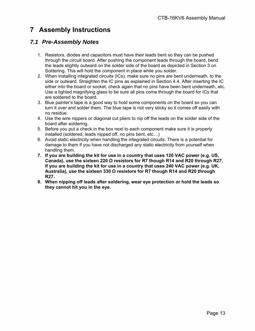
7.1 Pre-Assembly Notes
1. Resistors, diodes and capacitors must have their leads bent so they can be pushed through the circuit board. After pushing the component leads through the board, bend the leads slightly outward on the solder side of the board as depicted in Section 3 on Soldering. This will hold the component in place while you solder.
2. When installing integrated circuits (ICs), make sure no pins are bent underneath, to the side or outward. Straighten the IC pins as explained in Section 4.4. After inserting the IC either into the board or socket, check again that no pins have been bent underneath, etc. Use a lighted magnifying glass to be sure all pins come through the board for ICs that are soldered to the board.
3. Blue painter’s tape is a good way to hold some components on the board so you can turn it over and solder them. The blue tape is not very sticky so it comes off easily with no residue.
4. Use the wire nippers or diagonal cut pliers to nip off the leads on the solder side of the board after soldering.
5. Before you put a check in the box next to each component make sure it is properly installed (soldered, leads nipped off, no pins bent, etc…)
6. Avoid static electricity when handling the integrated circuits. There is a potential for damage to them if you have not discharged any static electricity from yourself when handling them.
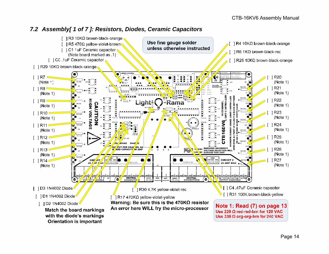
7. If you are building the kit for use in a country that uses 120 VAC power (e.g. US, Canada), use the sixteen 220 Ω resistors for R7 though R14 and R20 through R27. If you are building the kit for use in a country that uses 240 VAC power (e.g. UK, Australia), use the sixteen 330 Ω resistors for R7 though R14 and R20 through R27.
8. When nipping off leads after soldering, wear eye protection or hold the leads so they cannot hit you in the eye.
CTB-16KV6 Assembly Manual
Page 14
7.2 Assembly[ 1 of 7 ]: Resistors, Diodes, Ceramic Capacitors
CTB-16KV6 Assembly Manual
Page 15
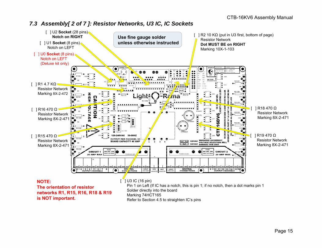
7.3 Assembly[ 2 of 7 ]: Resistor Networks, U3 IC, IC Sockets
[ ] U0 Socket (8 pins) Notch on LEFT (Deluxe kit only)
[ ] U1 Socket (8 pins) Notch on LEFT
[ ] U2 Socket (28 pins)Notch on RIGHT
[ ] U3 IC (16 pin) Pin 1 on Left (If IC has a notch, this is pin 1; if no notch, then a dot marks pin 1 Solder directly into the board Marking 74HCT165 Refer to Section 4.5 to straighten IC’s pins
[ ] R2 10 KΩ (put in U3 first, bottom of page) Resistor Network
Dot MUST BE on RIGHT Marking 10X-1-103
[ ] R1 4.7 KΩ Resistor Network Marking 8X-2-472
[ ] R16 470 Ω Resistor Network Marking 8X-2-471
[ ] R15 470 Ω Resistor Network Marking 8X-2-471
[ ] R18 470 Ω Resistor Network Marking 8X-2-471
[ ] R19 470 Ω Resistor Network Marking 8X-2-471
Use fine gauge solder unless otherwise instructed
NOTE:The orientation of resistornetworks R1, R15, R16, R18 & R19 is NOT important.
CTB-16KV6 Assembly Manual
Page 16
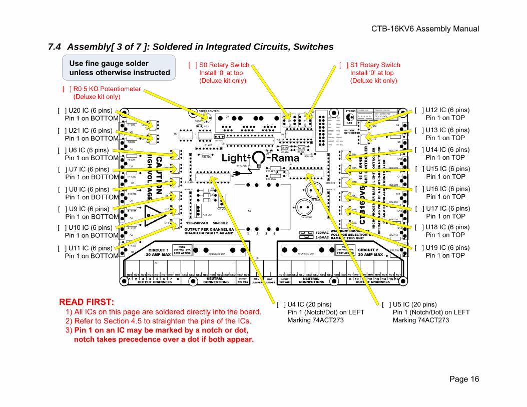
7.4 Assembly[ 3 of 7 ]: Soldered in Integrated Circuits, Switches
[ ] U20 IC (6 pins) Pin 1 on BOTTOM
[ ] U21 IC (6 pins) Pin 1 on BOTTOM
[ ] U6 IC (6 pins) Pin 1 on BOTTOM
[ ] U7 IC (6 pins) Pin 1 on BOTTOM
[ ] U8 IC (6 pins) Pin 1 on BOTTOM
[ ] U9 IC (6 pins) Pin 1 on BOTTOM[ ] U10 IC (6 pins) Pin 1 on BOTTOM
[ ] U11 IC (6 pins) Pin 1 on BOTTOM
[ ] U12 IC (6 pins) Pin 1 on TOP
[ ] U13 IC (6 pins) Pin 1 on TOP
[ ] U14 IC (6 pins) Pin 1 on TOP
[ ] U15 IC (6 pins) Pin 1 on TOP
[ ] U16 IC (6 pins) Pin 1 on TOP
[ ] U17 IC (6 pins) Pin 1 on TOP[ ] U18 IC (6 pins) Pin 1 on TOP
[ ] U19 IC (6 pins) Pin 1 on TOP
READ FIRST: 1) All ICs on this page are soldered directly into the board. 2) Refer to Section 4.5 to straighten the pins of the ICs. 3) Pin 1 on an IC may be marked by a notch or dot, notch takes precedence over a dot if both appear.
[ ] U4 IC (20 pins) Pin 1 (Notch/Dot) on LEFT Marking 74ACT273
[ ] U5 IC (20 pins) Pin 1 (Notch/Dot) on LEFT Marking 74ACT273
[ ] R0 5 KΩ Potentiometer (Deluxe kit only)
[ ] S0 Rotary Switch Install ‘0’ at top (Deluxe kit only)
[ ] S1 Rotary Switch Install ‘0’ at top (Deluxe kit only)
Use fine gauge solder unless otherwise instructed
CTB-16KV6 Assembly Manual
Page 17
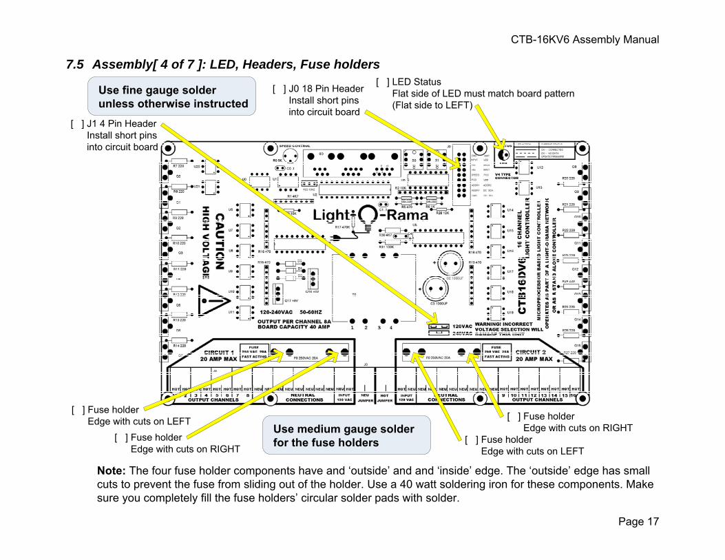
7.5 Assembly[ 4 of 7 ]: LED, Headers, Fuse holders [ ] LED Status Flat side of LED must match board pattern (Flat side to LEFT)
[ ] J0 18 Pin Header Install short pins into circuit board
[ ] J1 4 Pin Header Install short pins into circuit board
Note: The four fuse holder components have and ‘outside’ and and ‘inside’ edge. The ‘outside’ edge has small cuts to prevent the fuse from sliding out of the holder. Use a 40 watt soldering iron for these components. Make sure you completely fill the fuse holders’ circular solder pads with solder.
[ ] Fuse holder Edge with cuts on LEFT
[ ] Fuse holder Edge with cuts on RIGHT
[ ] Fuse holder Edge with cuts on RIGHT
[ ] Fuse holder Edge with cuts on LEFT
Use medium gauge solder for the fuse holders
Use fine gauge solder unless otherwise instructed
CTB-16KV6 Assembly Manual
Page 18
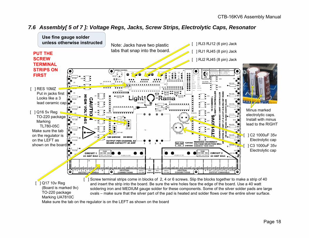
7.6 Assembly[ 5 of 7 ]: Voltage Regs, Jacks, Screw Strips, Electrolytic Caps, Resonator
[ ] RJ3 RJ12 (6 pin) Jack
[ ] RJ1 RJ45 (8 pin) Jack
[ ] RJ2 RJ45 (8 pin) Jack
Note: Jacks have two plastic tabs that snap into the board.
[ ] C2 1000uF 35v Electrolytic cap
[ ] Q16 5v Reg TO-220 package Marking TL780-05C Make sure the tab on the regulator is on the LEFT as shown on the board
[ ] Q17 10v Reg (Board is marked 9v) TO-220 package Marking UA7810C Make sure the tab on the regulator is on the LEFT as shown on the board
[ ] Screw terminal strips come in blocks of 2, 4 or 6 screws. Slip the blocks together to make a strip of 40 and insert the strip into the board. Be sure the wire holes face the edge of the board. Use a 40 watt soldering iron and MEDIUM gauge solder for these components. Some of the silver solder pads are large ovals – make sure that the silver part of the pad is heated and solder flows over the entire silver surface.
PUT THE SCREW TERMINAL STRIPS ON FIRST
[ ] RES 10MZ Put in jacks first Looks like a 3 lead ceramic cap
Use fine gauge solder unless otherwise instructed
[ ] C3 1000uF 35v Electrolytic cap
Minus markedelectrolytic caps.Install with minuslead to the RIGHT
CTB-16KV6 Assembly Manual
Page 19
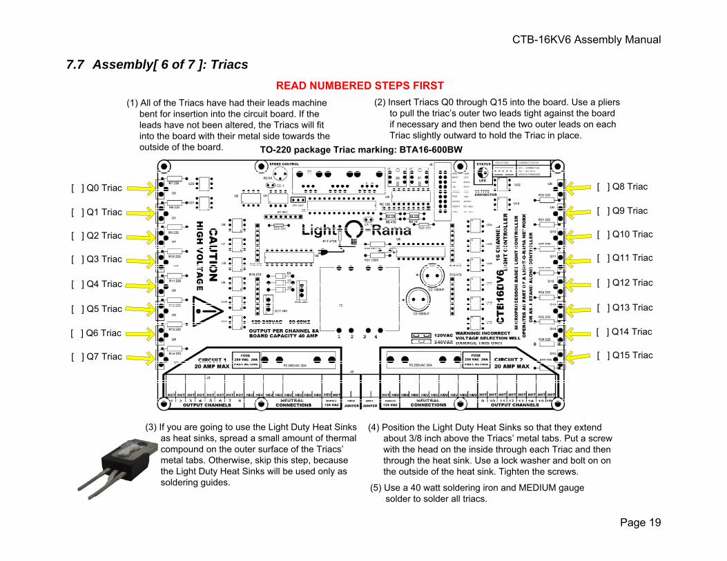
7.7 Assembly[ 6 of 7 ]: Triacs
(1) All of the Triacs have had their leads machine bent for insertion into the circuit board. If the leads have not been altered, the Triacs will fit into the board with their metal side towards the outside of the board.
(2) Insert Triacs Q0 through Q15 into the board. Use a pliers to pull the triac’s outer two leads tight against the board if necessary and then bend the two outer leads on each Triac slightly outward to hold the Triac in place.
TO-220 package Triac marking: BTA16-600BW
[ ] Q0 Triac
[ ] Q1 Triac
[ ] Q2 Triac
[ ] Q3 Triac
[ ] Q4 Triac
[ ] Q5 Triac
[ ] Q6 Triac
[ ] Q7 Triac
[ ] Q8 Triac
[ ] Q9 Triac
[ ] Q10 Triac
[ ] Q11 Triac
[ ] Q12 Triac
[ ] Q13 Triac
[ ] Q14 Triac
[ ] Q15 Triac
READ NUMBERED STEPS FIRST
(4) Position the Light Duty Heat Sinks so that they extend about 3/8 inch above the Triacs’ metal tabs. Put a screw with the head on the inside through each Triac and then through the heat sink. Use a lock washer and bolt on on the outside of the heat sink. Tighten the screws.
(5) Use a 40 watt soldering iron and MEDIUM gauge solder to solder all triacs.
(3) If you are going to use the Light Duty Heat Sinks as heat sinks, spread a small amount of thermal compound on the outer surface of the Triacs’ metal tabs. Otherwise, skip this step, because the Light Duty Heat Sinks will be used only as soldering guides.
CTB-16KV6 Assembly Manual
Page 20
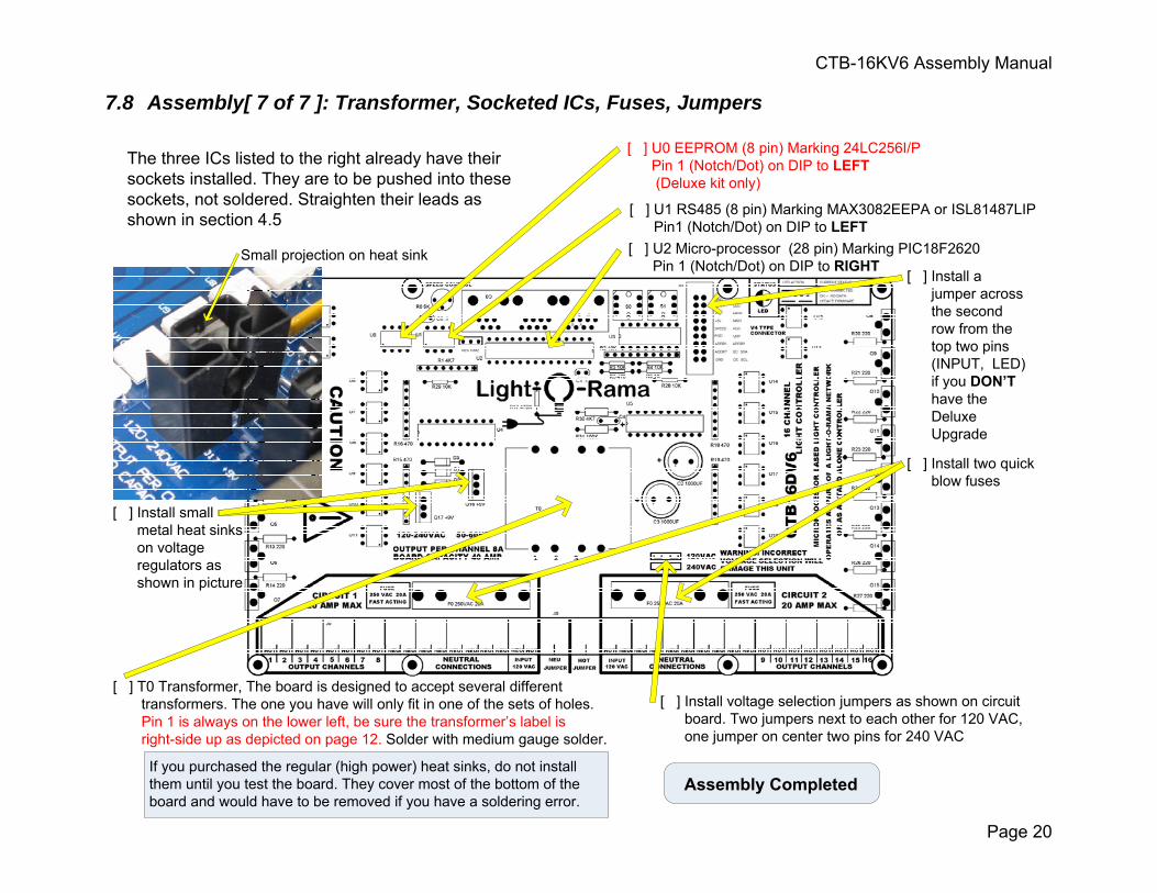
7.8 Assembly[ 7 of 7 ]: Transformer, Socketed ICs, Fuses, Jumpers
The three ICs listed to the right already have their sockets installed. They are to be pushed into these sockets, not soldered. Straighten their leads as shown in section 4.5
[ ] T0 Transformer, The board is designed to accept several different transformers. The one you have will only fit in one of the sets of holes.
Pin 1 is always on the lower left, be sure the transformer’s label is right-side up as depicted on page 12. Solder with medium gauge solder.
[ ] U0 EEPROM (8 pin) Marking 24LC256I/P Pin 1 (Notch/Dot) on DIP to LEFT (Deluxe kit only)
[ ] U1 RS485 (8 pin) Marking MAX3082EEPA or ISL81487LIP Pin1 (Notch/Dot) on DIP to LEFT[ ] U2 Micro-processor (28 pin) Marking PIC18F2620 Pin 1 (Notch/Dot) on DIP to RIGHT
[ ] Install two quick blow fuses
[ ] Install voltage selection jumpers as shown on circuit board. Two jumpers next to each other for 120 VAC, one jumper on center two pins for 240 VAC
Assembly Completed
[ ] Install a jumper across the second row from the top two pins (INPUT, LED) if you DON’T have the Deluxe Upgrade
If you purchased the regular (high power) heat sinks, do not install them until you test the board. They cover most of the bottom of the board and would have to be removed if you have a soldering error.
Small projection on heat sink
[ ] Install small metal heat sinks on voltage regulators as shown in picture
CTB-16KV6 Assembly Manual
Page 21
7.9 Post-Assembly Checks
Use a lighted magnifying glass
• Check that all diodes, resistor networks, ICs and the electrolytic capacitor are properly oriented.
• Check that all components are actually soldered, that the joints are smooth and shiny and that there are no solder bridges.
• Verify that R17 is really the 470 KΩ (yellow-violet-yellow-gold) resistor – an error here will fry the micro-processor.
• Check that the jumpers next to the power transformer are set for the proper line voltage.
• If you have the Standard Kit, make sure the jumper is across the second row from the top of J0, otherwise software unit selection will not work.
• The low voltage electronics on the board are powered by the right bank power feed, so connecting only the left side of the board to AC power will not power the micro-processor.
Refer to the CTB16D Users Guide to test your unit.
CAUTION: This product requires that you have an understanding of electrical wiring. This board requires connection to 120 or 240 Volts AC. It has many exposed high voltage connections that are potentially dangerous. This board should be placed in a safe enclosure to protect against electrocution whenever it is powered.
CTB-16KV6 Assembly Manual
Page 22
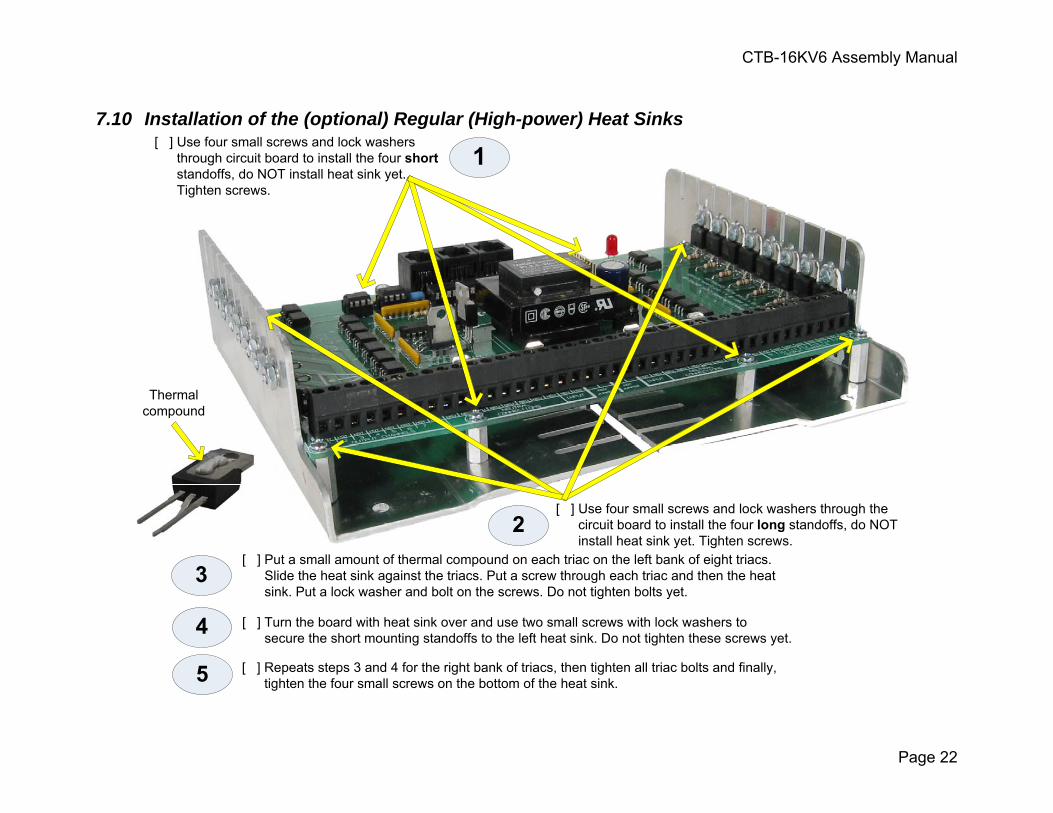
7.10 Installation of the (optional) Regular (High-power) Heat Sinks
[ ] Use four small screws and lock washers through the circuit board to install the four long standoffs, do NOT install heat sink yet. Tighten screws.
[ ] Use four small screws and lock washers through circuit board to install the four short
standoffs, do NOT install heat sink yet. Tighten screws.
[ ] Put a small amount of thermal compound on each triac on the left bank of eight triacs. Slide the heat sink against the triacs. Put a screw through each triac and then the heat sink. Put a lock washer and bolt on the screws. Do not tighten bolts yet.
Thermalcompound
[ ] Turn the board with heat sink over and use two small screws with lock washers to secure the short mounting standoffs to the left heat sink. Do not tighten these screws yet.
2
3
4
5 [ ] Repeats steps 3 and 4 for the right bank of triacs, then tighten all triac bolts and finally, tighten the four small screws on the bottom of the heat sink.


![Package ‘kyotil’ › web › packages › kyotil › kyotil.pdf · Jason Becker [ctb], Bendix Carstensen [ctb], Daryl Morris [ctb], Josh Pasek [ctb], Dennis Chao [ctb], Andri](https://static.fdocuments.in/doc/165x107/5f1a10767e663e367f7f2769/package-akyotila-a-web-a-packages-a-kyotil-a-kyotilpdf-jason-becker.jpg)


![Package ‘broom’ - The Comprehensive R Archive Network · Michelle Evans [ctb], Jason Cory Brunson [ctb], Simon Jackson [ctb], Ben Whalley [ctb], Michael Kuehn [ctb], Jorge Cimentada](https://static.fdocuments.in/doc/165x107/5f03a8507e708231d40a21aa/package-abrooma-the-comprehensive-r-archive-network-michelle-evans-ctb.jpg)