CT111 Introduction to Communication Systems Lecture 9 ...
26
Introduction Models and Functionalities Detailed Block Diagrams Analog to Digital Conversion CT111 Introduction to Communication Systems Lecture 9: Digital Communications Yash M. Vasavada Associate Professor, DA-IICT, Gandhinagar 31st January 2018 Yash M. Vasavada (DA-IICT) CT111: Intro to Comm. Systems 31st January 2018 1 / 17
Transcript of CT111 Introduction to Communication Systems Lecture 9 ...

Introduction Models and Functionalities Detailed Block Diagrams Analog to Digital Conversion
CT111 Introduction to Communication SystemsLecture 9: Digital Communications
Yash M. Vasavada
Associate Professor, DA-IICT, Gandhinagar
31st January 2018
Yash M. Vasavada (DA-IICT) CT111: Intro to Comm. Systems 31st January 2018 1 / 17

Introduction Models and Functionalities Detailed Block Diagrams Analog to Digital Conversion
Overview of Today’s Talk1 Introduction2 Models and Functionalities3 Detailed Block Diagrams4 Analog to Digital Conversion
Sampling in Time Domain
Yash M. Vasavada (DA-IICT) CT111: Intro to Comm. Systems 31st January 2018 2 / 17
Introduction Models and Functionalities Detailed Block Diagrams Analog to Digital Conversion
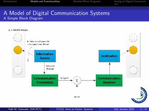
A Model of Digital Communication SystemsA Simple Block Diagram
Yash M. Vasavada (DA-IICT) CT111: Intro to Comm. Systems 31st January 2018 3 / 17
Introduction Models and Functionalities Detailed Block Diagrams Analog to Digital Conversion
A Model of Digital Communication SystemsA Simple Block Diagram
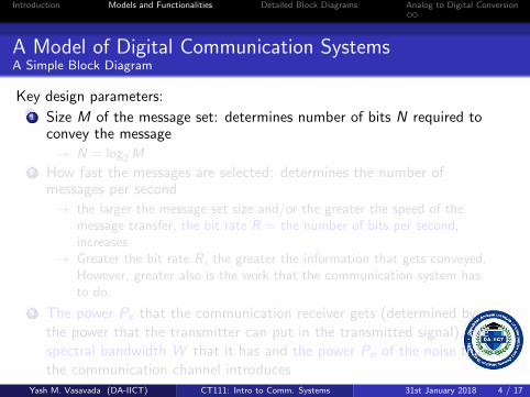
Key design parameters:1 Size M of the message set: determines number of bits N required to
convey the message
→ N = log2 M2 How fast the messages are selected: determines the number of
messages per second
→ the larger the message set size and/or the greater the speed of themessage transfer, the bit rate R = the number of bits per second,increases
→ Greater the bit rate R, the greater the information that gets conveyed.However, greater also is the work that the communication system hasto do.
3 The power Ps that the communication receiver gets (determined bythe power that the transmitter can put in the transmitted signal), thespectral bandwidth W that it has and the power Pn of the noise thatthe communication channel introduces
Yash M. Vasavada (DA-IICT) CT111: Intro to Comm. Systems 31st January 2018 4 / 17

Introduction Models and Functionalities Detailed Block Diagrams Analog to Digital Conversion
A Model of Digital Communication SystemsA Simple Block Diagram
Key design parameters:1 Size M of the message set: determines number of bits N required to
convey the message
→ N = log2 M2 How fast the messages are selected: determines the number of
messages per second
→ the larger the message set size and/or the greater the speed of themessage transfer, the bit rate R = the number of bits per second,increases
→ Greater the bit rate R, the greater the information that gets conveyed.However, greater also is the work that the communication system hasto do.
3 The power Ps that the communication receiver gets (determined bythe power that the transmitter can put in the transmitted signal), thespectral bandwidth W that it has and the power Pn of the noise thatthe communication channel introduces
Yash M. Vasavada (DA-IICT) CT111: Intro to Comm. Systems 31st January 2018 4 / 17

Introduction Models and Functionalities Detailed Block Diagrams Analog to Digital Conversion
A Fundamental Limit on CommunicationsShannon Information Theory
→ The celebratedrelationship:
R ≤W log2
(1 +
Ps
Pn
)
Yash M. Vasavada (DA-IICT) CT111: Intro to Comm. Systems 31st January 2018 5 / 17

Introduction Models and Functionalities Detailed Block Diagrams Analog to Digital Conversion
Bandwidth Efficiency ηB
As data rate R increases, the pulse width of transmitted signalreduces and therefore the bandwidth B, which is inverselyproportional to the transmitted pulse width, increases.This cannot be avoided; however some schemes use the availablebandwidth more efficiently than the othersWe will denote the ratio R/W as the bandwidth efficiency ηB .It is obviously better to have ηB as large as possible. However, thereis a cost associated to making ηB large.
Yash M. Vasavada (DA-IICT) CT111: Intro to Comm. Systems 31st January 2018 6 / 17

Introduction Models and Functionalities Detailed Block Diagrams Analog to Digital Conversion
Energy Efficiency ηE
Communication systems are characterized by the signal to noise ratio(SNR) Ps/Pn required to attain a certain performanceTypically improving ηB (making it large) requires SNR Ps/Pn to beincreased
We will define energy efficiency ηE as
(Ps
Pn
)−1
required to attain
some excellent communication performance (e.g., only one bit out of105 bits is in error on average).
Greater the requiredPs
Pn, the smaller the energy efficiency.
Yash M. Vasavada (DA-IICT) CT111: Intro to Comm. Systems 31st January 2018 7 / 17

Introduction Models and Functionalities Detailed Block Diagrams Analog to Digital Conversion
Fight between ηE and ηB
As it often is the case in the life, it is hard to get best of both theworlds.
. An increase in ηB translates to a decrease in ηE and vice versa.
Trade-off between bandwidth and energy efficiencies can be viewed asthe equivalence between the power and the bandwidth
. If the system designer has a fixed transmit power (i.e., the design islimited or handicapped by the transmit power), this limit can beovercome to some extent by increasing the bandwidth
. Vice versa, if the bandwidth is limited, the power can be increased toobtain the desired data rate
Yash M. Vasavada (DA-IICT) CT111: Intro to Comm. Systems 31st January 2018 8 / 17

Introduction Models and Functionalities Detailed Block Diagrams Analog to Digital Conversion
Comparisonof a Digital with Analog Method of Communication
In both the digital and the analog communications. . .
. the information (or the message) signal that is getting transferred overthe communication link is often analog
. Actual (physical) signal that is transmitted over the communicationchannel is also almost always analog, i.e., continuous in time and oftencontinuous in the amplitudes (voltage)
It is the modulation scheme that determines whether thecommunication system is called analog or digital.
. In digital communications, the analog information signal is digitized(discrete-time and discrete-levels of amplitude), and it is this digitizedmessage that modulates the transmitted analog signal
. In analog communication, the analog information directly modulatesthe transmitted analog signal
Yash M. Vasavada (DA-IICT) CT111: Intro to Comm. Systems 31st January 2018 9 / 17

Introduction Models and Functionalities Detailed Block Diagrams Analog to Digital Conversion
Block Diagramof an Analog Communication Transceiver
Yash M. Vasavada (DA-IICT) CT111: Intro to Comm. Systems 31st January 2018 10 / 17

Introduction Models and Functionalities Detailed Block Diagrams Analog to Digital Conversion
Block Diagramof an Analog Communication Transceiver
Yash M. Vasavada (DA-IICT) CT111: Intro to Comm. Systems 31st January 2018 11 / 17

Introduction Models and Functionalities Detailed Block Diagrams Analog to Digital Conversion
Why Digital CommunicationsInstead of Analog
Compared to analog communication systems, the digitalcommunications. . .
1 Allows approaching the Shannon Capacity bound more closely (resultsthat are only 0.04 dB away from Shannon bound have been obtained)
2 Provides a better tradeoff of bandwidth efficiency against energyefficiency (i.e., exchange the power with the bandwidth).
3 Has a better ability to compensate for the effect of noise (any noiseintroduces irrecoverable distortion in the analog signal. Incomparison, the a digital receiver needs to distinguish only a finitenumber of transmitted data. Thus, it is possible to completelyremove the effect of noise)
4 Allows use of many performance enhancing signal processingtechniques, such as source coding, channel coding, encryption, etc.
Yash M. Vasavada (DA-IICT) CT111: Intro to Comm. Systems 31st January 2018 12 / 17

Introduction Models and Functionalities Detailed Block Diagrams Analog to Digital Conversion
Why Digital CommunicationsInstead of Analog
In addition
Digital technology, for which the primary currency is bits (DigitalIntegrated Circuits (ICs), and in general, the computers and thesmartphones and their networks), has become very powerful and areinexpensive to manufacture.Digital Communications allows integration of voice, video and data ona single packet networking system.
Yash M. Vasavada (DA-IICT) CT111: Intro to Comm. Systems 31st January 2018 13 / 17
Introduction Models and Functionalities Detailed Block Diagrams Analog to Digital Conversion
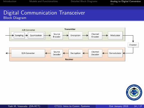
Digital Communication TransceiverBlock Diagram
Yash M. Vasavada (DA-IICT) CT111: Intro to Comm. Systems 31st January 2018 14 / 17

Introduction Models and Functionalities Detailed Block Diagrams Analog to Digital Conversion
Digital Communication TransceiverBlock Diagram
We will now be looking at the process of quantization of an analoginformation source
Yash M. Vasavada (DA-IICT) CT111: Intro to Comm. Systems 31st January 2018 15 / 17

Introduction Models and Functionalities Detailed Block Diagrams Analog to Digital Conversion
Sampling in Time Domain
Discrete-Time Representations of Continuous-Time Signals
Examples of Continuous Time (C-T) signals: video, voice, image, etc.Sampling theorem says that if the C-Tsignal is band limited, it can beexactly recovered by its time domain samples taken sufficiently closetogether
→ Sampling analog signals makes them discrete in time→ For band-limited signal, the ideal sampling scheme introduces no
distortion
Yash M. Vasavada (DA-IICT) CT111: Intro to Comm. Systems 31st January 2018 16 / 17
Introduction Models and Functionalities Detailed Block Diagrams Analog to Digital Conversion
Sampling in Time Domain
Sampling Theorem
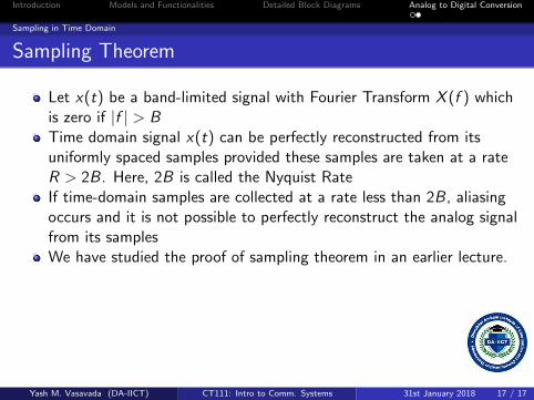
Let x(t) be a band-limited signal with Fourier Transform X (f ) whichis zero if |f | > BTime domain signal x(t) can be perfectly reconstructed from itsuniformly spaced samples provided these samples are taken at a rateR > 2B. Here, 2B is called the Nyquist RateIf time-domain samples are collected at a rate less than 2B, aliasingoccurs and it is not possible to perfectly reconstruct the analog signalfrom its samplesWe have studied the proof of sampling theorem in an earlier lecture.
Yash M. Vasavada (DA-IICT) CT111: Intro to Comm. Systems 31st January 2018 17 / 17