CT Scan Site Manual of Operations Visit 2 8... · JHS Manual 8_V 1.0 01 30 2007 Jackson Heart Study...
30
JHS Manual 8_V 1.0 01302007 Jackson Heart Study (JHS) Manual 8 CT Scan Site Manual of Operations Visit 2 Version 1.0 January 12, 2007 For Copies, Please Contact: Jackson Heart Study Coordinating Center Jackson Medical Mall 350 W. Woodrow Wilson Drive Jackson, MS 39213
Transcript of CT Scan Site Manual of Operations Visit 2 8... · JHS Manual 8_V 1.0 01 30 2007 Jackson Heart Study...

JHS Manual 8_V 1.0 01302007
Jackson Heart Study (JHS)
Manual 8
CT Scan Site Manual of Operations
Visit 2
Version 1.0
January 12, 2007
For Copies, Please Contact:
Jackson Heart Study Coordinating Center Jackson Medical Mall
350 W. Woodrow Wilson Drive Jackson, MS 39213


JHS Manual 8_V 1.0 01302007
I
FOREWORD
This manual is one of a series of protocols and manuals of operation for the Jackson Heart Study (JHS). The complexity of the JHS requires that a sizeable number of procedures be described, thus this rather extensive list of materials has been organized into the set of manuals listed below. Manual 1 provides the background, organization, and general objectives of the JHS Study. Manuals 2 and 4 describe the operation of the Cohort Procedures, Blood Pressure and Events Ascertainment Components of the study. Detailed Manuals of Operation for specific procedures, including those for Blood Pressure and Quality Assurance, make up Manuals 4 and 5. The Data Management System is described in Manual 6. The Central Laboratory and Specimen Repository is described in Manual 7. Manual 8 is designed to provide volumetric CT image data for measuring coronary and abdominal aortic calcified plaque as well as measuring body composition in the abdomen.
JHS Study Protocols and Manuals of Operation
MANUAL TITLE
1 General Description and Study Management
2 Cohort Component Procedures
3 Blood Pressure
4 Morbidity Mortality Classification Manual /Cohort Events Ascertainment
5 Quality Assurance
6 Data Management
7 Central Laboratory and Specimen Repository Collection and Processing
8 Computed Tomography (CT) Scan

II

JHS Manual 8_V 1.0 01302007
III
Manual 8 CT Scan
TABLE OF CONTENTS
1. Introduction ...................................................................................................................................... 1
2. CT Exam Protocol and Procedures ................................................................................................. 1 2.1 Field Center Scheduling ......................................................................................................... 1 2.2 CT Exam Overview ............................................................................................................... 2 2.3 Entering Participant Identifying Information ............................................................................ 3 2.4 PreCT Exam Activities ............................................................................................................ 3 2.5 Participant Preparation at the CT Scan Site ............................................................................ 3 2.6 Positioning the Participant and Calcium QCT Phantom on CT Couch .................................... 4 2.7 Scout Image of the Thorax ...................................................................................................... 4 2.8 Heart 1 CT Scan Series ........................................................................................................... 5 2.9 Breathing Instructions ............................................................................................................. 6 2.10 Limited Lower Abdominal Aorta CT series (L3S1)................................................................... 7
3. Radiation Dose Estimates for the CT Exam ..................................................................................... 8 3.1 Introduction ............................................................................................................................ 8 3.2 Informing Participants of Radiation Exposure............................................................................ 9 3.3 Detailed Discussion of Doses Estimates................................................................................... 10 3.4 Effective Dose Calculations ...................................................................................................... 10 3.5 Informing participants of Radiation exposure: ........................................................................... 11
4. CT Scan Site Procedures for Secure Networking of CT Image to Walker Forest University CTRC ................................................................................................... 11
5. CT Scanner Quality Assurance Procedures..................................................................................... 12 5.1 CT System Certification and QA Process ................................................................................. 12 5.2 CT Initial Certification ............................................................................................................... 12 5.3 CT Calibration ........................................................................................................................ 12
6. CT Technologist Training................................................................................................................ 14
Appendices ............................................................................................................................................... 16 A CT Central Training Curriculum ....................................................................................... 17 B CT Scanning Worksheet .................................................................................................. 19 C The CT Technical Parameters for each CT System ......................................................... 21 D CT Technologist Training & Certification Logs ................................................................. 23 E Draft CT Technologist Electronic Training Material ........................................................... * F CARDIA/MESA CT Methods Paper ................................................................................. *
(* attached as separate files secondary to size considerations)

IV

JHS Manual 8_V 1.0 01302007
1
1. Introduction
The Jackson Heart Study (JHS) is a singlesite prospective epidemiologic investigation of cardiovascular disease (CVD) among AfricanAmericans from the Jackson, Mississippi metropolitan area. This study represents an expansion of one of the study sites of the Atherosclerosis Risk in Communities (ARIC) Study which included four geographically diverse communities in the U.S. (northwestern suburbs of Minneapolis, Minnesota; Washington County, Maryland; Forysth County, North Carolina; and the city of Jackson, Mississippi).
TRAINING OF TECHNOLOGISTS
Dr. Carr has performed onsite training January 1012, 2007. The training sessions included didactic, small groups and hands on training. Following the course the technologists will complete the certification test and observe CT scans of participants and QC procedures. They will leave with a comprehensive understanding of the CT protocol. It is anticipated that upon completion they will be “Provisionally Certified”. They will have knowledge and training material for the other technologists at their site. During the pilot phase the technologists will complete the 3 certification exams on their CT system. Each of these scans will also be rated on technical quality criteria and immediate feedback will be provided. These exams will be reviewed by the CTRC personnel and either further training for full certification will occur.
2. CT Exam Protocol and Procedures
2.1 Field Center Scheduling
The JHS local investigators will arrange details of scheduling participants for the CT exam. Scheduling details will be mutually agreed upon between the CT scanning center and Field Center. A Field Center interviewer/scheduler will be responsible for explaining and obtaining consent for the CT examination including pregnancy screenings. Participants will be scheduled for a certain date and time, and escorted to the CT scanner. The Field Center will take the participant and CT Scan Worksheet (see Appendix B) which identifies the participant by name. The CT Technologists need to have the individual’s real name to confirm identity. The CT Scan Worksheet provides the detailed information required by the CT scanning sites for labeling and performing the CT exam (See Appendix B).
Required information for the CT scheduling form includes the participant’s name (for scheduling and greeting purposes only), participant’s weight (as recorded at the clinic visit), and date of birth, JHS study ID and a secondary identifier called the “alpha code” which will replace the participant’s real name.
2.2 CT Exam Overview
The CT examination is designed to provide volumetric CT image data for measuring coronary and abdominal aortic calcified plaque as well as measuring body composition in the abdomen. The exam consists of scout images and one ECG gated series of the entire heart and a series through the lower abdomen. On average, 15 minutes of participant time will be spent within the CT scan suite; this includes instructions, setup and imaging. In rare cases, the exam may

2
require 20 minutes. In many cases, the examination will be completed in less than 10 minutes. Participants will have ECG electrodes attached (according to your vendors recommendations) for cardiac gating and be instructed as to a standardized breath holding instructions.
Figure 1 CT Exam – Detail of CT scan Series:
Series Description No. of images
Scan time ECG gating
Series Description No. of images
Scan time ECG gating
1 Scout 2 < 8 sec no 2 Heart / Coronary
arteries 50 15 sec yes
3 Lower abdomen /L3S1 44 20 sec no 1 Scout images will consist of a frontal and lateral low energy 2D scanogram when possible 2 Duplicate scans will not be obtained of the coronary circulation since previous studies have demonstrated minimal add value. 3 Additional reconstructions will be made using a display fieldofview (DFOV) of 50 cm for the measurement of subcutaneous fat. These require no additional radiation exposure and simply represent additional copies of the already acquired data.
2.3 Entering Participant Identifying Information
The CT scanners to be used in this study store demographic, detailed scan technical information and the raw image data in the standard DICOM file format. Participant identifying information will be encrypted at each CT site for the following reasons: Safeguard participant confidentiality. Comply with federal requirements for medical information, Health Insurance Portability and Accountability Act of 1996 (HIPAA). Provide positive and redundant participant identification for CT image files now and in the future. The data coordinating system has assigned a unique study identification number for each participant. The exact method will be decided upon by the coordinating center and CT scan site. Below is a method we have successfully used in prior studies.
The Jackson Heart Study study identification number (“J” + 6 digits) will be entered in the field on the CT scanner where the local medical record numbers is typically placed. An “alpha code” (5 letters) will be entered in the name field. The participant’s weight, dateofbirth, ordering physician (Dr. Herman Taylor, interpreting physician (Dr. Mike Doherty), will be entered on the demographics page of the GE Lightspeed Pro 16 after pressing the “New Exam” button.
*** It is very important that you enter your technician ID initials on this screen. This may vary between CT vendors, but most systems have a field for entering the CT technologists name/initials. Please type your tech ID in this location. If you do not have a field for this on your CT scanner please call the CTRC for additional help in resolving this issue.

JHS Manual 8_V 1.0 01302007
3
Example CT Data Entry: Name BJDEC (Exact format TBD) ID number: J123456 Date of Birth 03 MAR 1947 Technologist JJC Gender Male Weight 175 Ordering Physician Dr. H. Taylor Interpreting Physician Dr. M. Doherty History JHS research CT exam
The series number and time stamp on each CT image will ensure proper identification of the respective series of the coronary and abdominal aorta CT scans. Scan technical data (site, CT scanner, kV, mA, fov, slice thickness, spatial resolution, kernal etc.) are automatically stored within the DICOM header as part of the DICOM standard for each image file and will be recorded and tracked by the CTRC.
2.4 PreCT Exam Activities
Subjects weighing more than 350 lbs (~160 kg) will be excluded from the CT exam. This exclusion is secondary to technical difficulties related to imaging individuals of this size and greater.
Pregnancy Screening: The field center personnel will ask women if they have the potential to be pregnant and complete pregnancy screening process as detailed in the Clinic Exam procedures.
CT inclusion criteria:
Enrolled in JHS study, eligible for the CT exam with signed consent obtained. Pregnancy screen completed if applicable
CT exclusion criteria:
1. Weight greater than 350 lbs (~160 kg). 2. Pregnant or pregnancy status unknown 3. Female participant < 40 years of age 4. Male participant < 35 years of age
2.5 Participant Preparation at the CT Scan Site
The CT Tech:
1. Reviews the CT Scan Worksheet with the JHS Study ID and alpha code.
The technologist will instruct the subject on the importance of breath holding and immobility during scanning. The technologist will attach 3 electrocardiography electrodes under the righ and left clavicle and on the left side of the thorax near the axilla (to maximize ECG signal) or as instructed by your equipment provider.
4
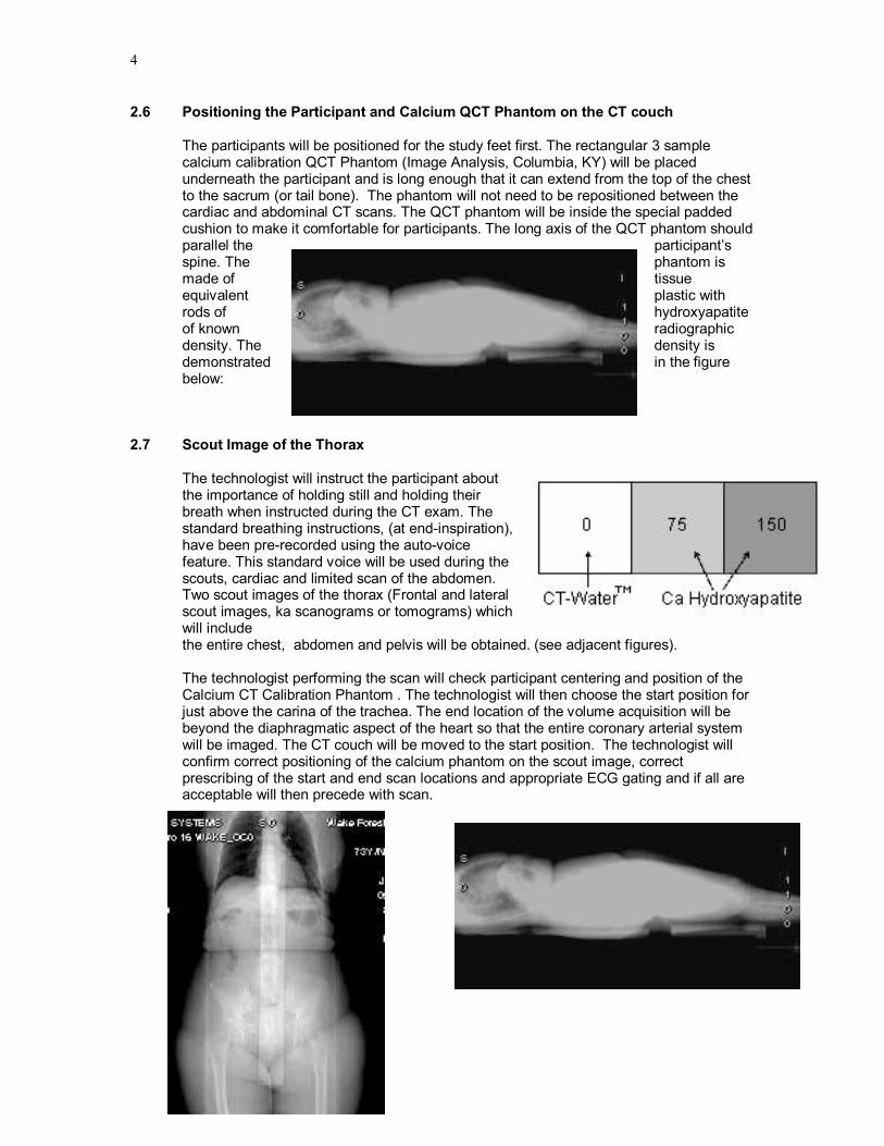
2.6 Positioning the Participant and Calcium QCT Phantom on the CT couch
The participants will be positioned for the study feet first. The rectangular 3 sample calcium calibration QCT Phantom (Image Analysis, Columbia, KY) will be placed underneath the participant and is long enough that it can extend from the top of the chest to the sacrum (or tail bone). The phantom will not need to be repositioned between the cardiac and abdominal CT scans. The QCT phantom will be inside the special padded cushion to make it comfortable for participants. The long axis of the QCT phantom should parallel the participant’s spine. The phantom is made of tissue equivalent plastic with rods of hydroxyapatite of known radiographic density. The density is demonstrated in the figure below:
2.7 Scout Image of the Thorax
The technologist will instruct the participant about the importance of holding still and holding their breath when instructed during the CT exam. The standard breathing instructions, (at endinspiration), have been prerecorded using the autovoice feature. This standard voice will be used during the scouts, cardiac and limited scan of the abdomen. Two scout images of the thorax (Frontal and lateral scout images, ka scanograms or tomograms) which will include the entire chest, abdomen and pelvis will be obtained. (see adjacent figures).
The technologist performing the scan will check participant centering and position of the Calcium CT Calibration Phantom . The technologist will then choose the start position for just above the carina of the trachea. The end location of the volume acquisition will be beyond the diaphragmatic aspect of the heart so that the entire coronary arterial system will be imaged. The CT couch will be moved to the start position. The technologist will confirm correct positioning of the calcium phantom on the scout image, correct prescribing of the start and end scan locations and appropriate ECG gating and if all are acceptable will then precede with scan.

JHS Manual 8_V 1.0 01302007
5
2.8 Heart 1 CT Scan Series
Scanning procedure for cardiac gated CT scans of the coronary arteries are based on the standard protocols developed as part of the NHLBI’s MESA and CARDIA studies (Carr et. al. Radiology 2005; 234(1):3543.) . To ensure complete coverage of the entire heart, a minimum of 10.5 cm of image data in the z direction (headtofoot) will be acquired with each scan. This coverage results in 4460 slices depending upon the length of the heart. The heart scans will be reconstructed centered on the heart using a display fieldofview of 35 cm. This will include the Calcium QCT phantom within the images as well as the majority of the lungs.
**** One of the CT quality factors is inclusion of the phantom on the cardiac CT images – the technologist should confirm that the entire QCT phantom (i.e. all four cylinders) are visible on each slice – if not reconstruct the images altering the leftright or anteriorposterior positioning while maintaining a 35 cm DFOV to include the entire phantom. ****************
Technical Parameters for each CT system is in Appendix C.
Participant Weight and the CT exam:
Participants weighing more than 350 lbs (~160 kg) will be excluded from the CT exam. As individuals become larger more Xray photons are stopped or attenuated by their tissue. This means that there are fewer photons making the trip through the participant to make an image. This results in decreased image quality. To compensate, the tube current (or mA) will be adjusted upwards (25%) for participants who weigh more than 100 Kg (220 lbs.) at their clinic visit. This is why clinic personnel must record weight on the CT completion form, in addition the CT tech must append the weight after the name. This adjustment, although imperfect, will maintain a more constant signaltonoise ratio (or photon flux) across participants of varying weights and result in improved image quality and calcium measurement. Note that this along with all the additional technical and demographic information including individual time stamps for the scan, scan series and individual image is recorded in the DICOM header which is part of each image and will be available on the CT image library of all the JHS studies as part of our quality control procedures.
Reconstruction Parameters:
The following technical parameters should be entered into a memorized protocol on each CT system, which should greatly facilitate protocol compliance. All series will be performed using the large scan fieldofview. This may also be referred to as the “body” as opposed to the “head” scan fieldofview. The technologist will reconstruct using a display or reconstruction fieldofview of 35 cm (or 350 mm).Why are we scanning the heart with a 35 cm fov? By reconstructing with a 35 cm fov we insure that the QCT phantom is included in the reconstructed images. It is very important when prescribing the scan to make sure that the anteriorposterior center is such that the entire phantom is included in the image. You will have to center AP behind the heart on individuals with very large chest. If while reviewing your images you see that

6
the phantom is partially clipped off, reconstruct the series with the appropriate AP offset. Be sure to check this on all studies and if necessary reconstruct to include the phantom on the images. The standard reconstruction kernel will be used for the two cardiac series. For the cardiac series, the 240 degree (cardiac CINE) segmented scan reconstruction algorithm will be used.
Additional Reconstructions: Two additional reconstructions of the same scan data will be made for measurements of surrounding tissues.
1. “Hires Recon” Thin slice reconstruction at 1.25 mm – these images allow better definition of potential plaque by using thinner slices and may be useful for future analyses related to plaque characterization.
2. “Max 50 cm Recon”. These images can be used along with the scout in future studies to obtain information about body composition with attention directed to the chest wall, muscles and fat.
Figure 2 Table CT Image Reconstruction Parameters
Series Scan FOV Display FOV Kernel Recon. type
Heart 1 Large / Body 350 mm GE=standard
Siem=b30f
Imatron=Sharp
240° (partial) quic k scan
2.9 Breathing Instructions
All CT scan sequences will be performed with suspended respiration and a single breath hold. The cardiac scan series will require participants to suspend respiration a variable amount of time, ranging from 10 to 15 seconds, depending upon the combination of heart rate and heart length. The technologist will instruct the participant as described above and then a standardized digitally recorded voice will provide breathing instructions. Breathing will be suspended at end inspiration to depress the diaphragm and liver for improved imaging of the heart.
Standardized Script for breathing instructions: ”Take a deep breath in… <5 sec. pause> ”Blow it all the way out… <5 sec. pause> ”Take a deep breath in… <5 sec. pause> ”Blow it all the way out… <5 sec. pause> ”Take a deep breath in and hold your breath ….. <15 second scan acquisition> ”Breathe and relax”
Though total imaging time will be less than 15 seconds, it will require about 5 to 7 minutes to complete.

JHS Manual 8_V 1.0 01302007
7
2.10 Limited Lower Abdominal Aorta CT series (L3S1) Scanning Procedures for the Aorta:
The scanning procedure described below will require approximately 510 minutes of the participant’s time. The technologist proceeds directly to prescribing the abdominal aorta scan from the initial scout image. The abdominal aorta protocol requires a lateral scout image to identify the disk spaces and vertebra of the lumbar spine. The technologist will identify the three lower lumbar vertebra and scan from mid L3 through S1. (See adjacent figure with the start and end locations designated by the thick red lines).
Helical Scan Acquisition of the Abdominal Aorta: The abdominal aortic scan will be prescribed graphically based on the location of L3 and S1 vertebra from the lateral scout image. Why are we using S1 as at landmark? The Lumbosacaral junction is the most easily identifiable and consistent landmark identified in the abdomen/pelvis. Our objective is for you to scan the entire aspect of the two lowest lumbar vertebra, typically L4 and L5. The protocol is designed to avoid imaging the true pelvis where in females the ovaries are located. We performed a study and have determined that 150 mm superior to S1 is above the renal arteries in all participants in our sample population. Other landmarks like the top of the diaphragm and counting the vertebral levels are variable between people and we believe are less reproducible. The CT scanners will be set at the technical parameters specified in the table below. Like in the cardiac scan we will adjust up the mA for those individuals that weigh more than 220 lbs.
Figure 3 CT Technical Parameter for the Abdominal Aorta Scan:
CT System Mode FOV Pitch 1 Kernel /recon
KV mA time mAs 2
GE LightSpeed Plus (WFU/MGH/UT)
Helical 35 & 50 cm
4i 3:1 HQ
Std / full
120 300 or 51 5
0.5 s 200 150
1 Note pitch on multidetector CT systems have been described with competing conventions by different vendors, thus for the Siemens & Marconi systems the pitch can be explained as 3:1 [7.5 mm table travel per rotation over a 2.5 mm slice collimation] or alternatively as 0.75:1 [7.5 mm table travel per rotation over a beam collimation of 10 mm (i.e. in 4 slice mode 2.5 mm x 4 = 10 mm beam collimation)]. 2 mAs for the Abdominal Aorta scan was reduced (decreasing participant exposure) in May 2002 after review of the initial images from the pilot / vanguard phase of the study.
Abdominal Aorta CT scan series will be acquired in the helical mode, full or 360° recon mode with a 2.5 mm slice collimation and a scan pitch of 3:1 or 0.75:1 depending upon the definition of pitch chosen by the CT scanner manufacturer for a particular system. A detailed definition of pitch is provided in the note below the table on technical factors. The CT Reading Center will confirm
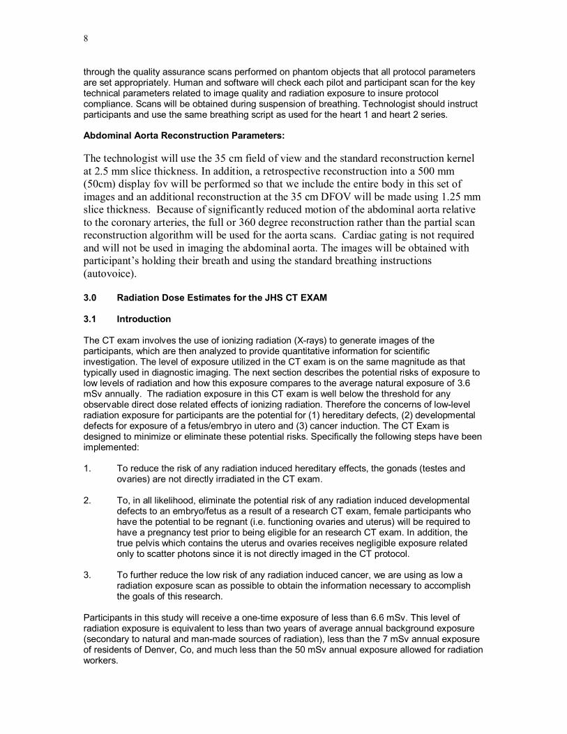
8
through the quality assurance scans performed on phantom objects that all protocol parameters are set appropriately. Human and software will check each pilot and participant scan for the key technical parameters related to image quality and radiation exposure to insure protocol compliance. Scans will be obtained during suspension of breathing. Technologist should instruct participants and use the same breathing script as used for the heart 1 and heart 2 series.
Abdominal Aorta Reconstruction Parameters:
The technologist will use the 35 cm field of view and the standard reconstruction kernel at 2.5 mm slice thickness. In addition, a retrospective reconstruction into a 500 mm (50cm) display fov will be performed so that we include the entire body in this set of images and an additional reconstruction at the 35 cm DFOV will be made using 1.25 mm slice thickness. Because of significantly reduced motion of the abdominal aorta relative to the coronary arteries, the full or 360 degree reconstruction rather than the partial scan reconstruction algorithm will be used for the aorta scans. Cardiac gating is not required and will not be used in imaging the abdominal aorta. The images will be obtained with participant’s holding their breath and using the standard breathing instructions (autovoice).
3.0 Radiation Dose Estimates for the JHS CT EXAM
3.1 Introduction
The CT exam involves the use of ionizing radiation (Xrays) to generate images of the participants, which are then analyzed to provide quantitative information for scientific investigation. The level of exposure utilized in the CT exam is on the same magnitude as that typically used in diagnostic imaging. The next section describes the potential risks of exposure to low levels of radiation and how this exposure compares to the average natural exposure of 3.6 mSv annually. The radiation exposure in this CT exam is well below the threshold for any observable direct dose related effects of ionizing radiation. Therefore the concerns of lowlevel radiation exposure for participants are the potential for (1) hereditary defects, (2) developmental defects for exposure of a fetus/embryo in utero and (3) cancer induction. The CT Exam is designed to minimize or eliminate these potential risks. Specifically the following steps have been implemented:
1. To reduce the risk of any radiation induced hereditary effects, the gonads (testes and ovaries) are not directly irradiated in the CT exam.
2. To, in all likelihood, eliminate the potential risk of any radiation induced developmental defects to an embryo/fetus as a result of a research CT exam, female participants who have the potential to be regnant (i.e. functioning ovaries and uterus) will be required to have a pregnancy test prior to being eligible for an research CT exam. In addition, the true pelvis which contains the uterus and ovaries receives negligible exposure related only to scatter photons since it is not directly imaged in the CT protocol.
3. To further reduce the low risk of any radiation induced cancer, we are using as low a radiation exposure scan as possible to obtain the information necessary to accomplish the goals of this research.
Participants in this study will receive a onetime exposure of less than 6.6 mSv. This level of radiation exposure is equivalent to less than two years of average annual background exposure (secondary to natural and manmade sources of radiation), less than the 7 mSv annual exposure of residents of Denver, Co, and much less than the 50 mSv annual exposure allowed for radiation workers.
JHS Manual 8_V 1.0 01302007
9
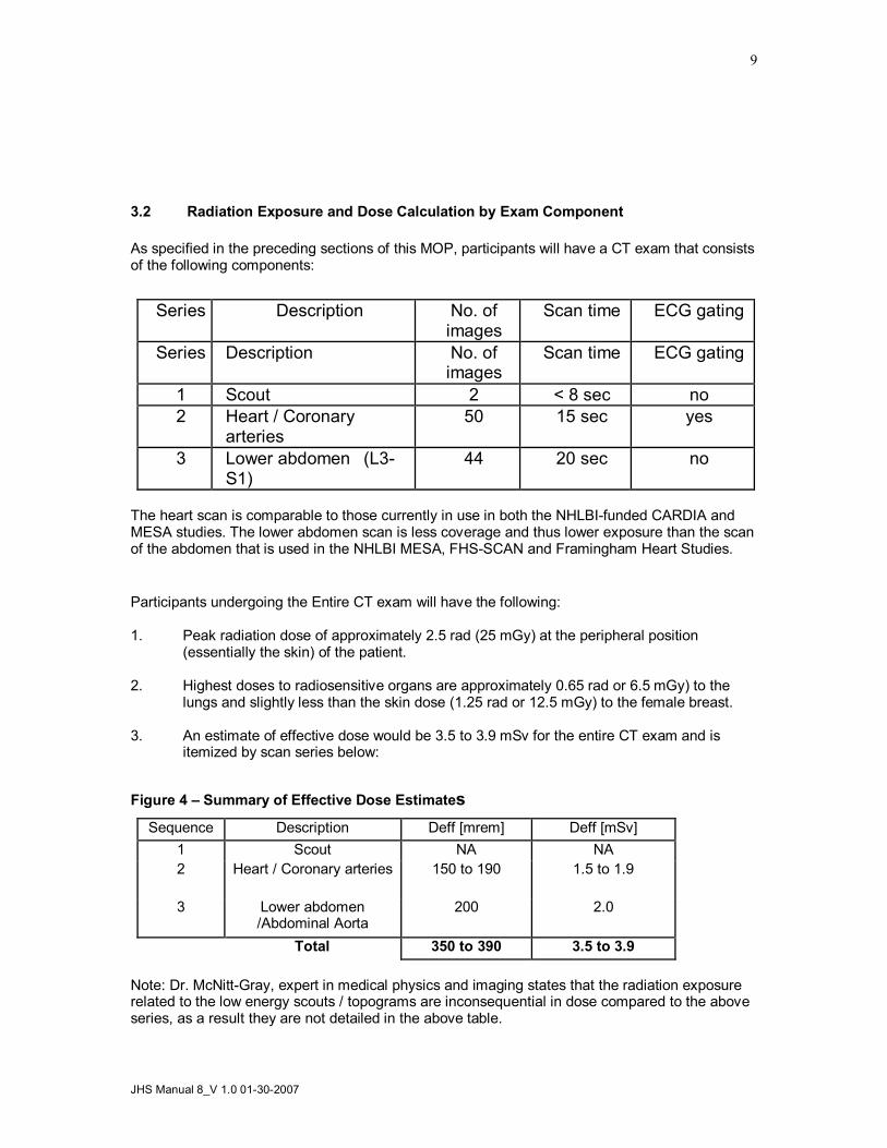
3.2 Radiation Exposure and Dose Calculation by Exam Component
As specified in the preceding sections of this MOP, participants will have a CT exam that consists of the following components:
Series Description No. of images
Scan time ECG gating
Series Description No. of images
Scan time ECG gating
1 Scout 2 < 8 sec no 2 Heart / Coronary
arteries 50 15 sec yes
3 Lower abdomen (L3 S1)
44 20 sec no
The heart scan is comparable to those currently in use in both the NHLBIfunded CARDIA and MESA studies. The lower abdomen scan is less coverage and thus lower exposure than the scan of the abdomen that is used in the NHLBI MESA, FHSSCAN and Framingham Heart Studies.
Participants undergoing the Entire CT exam will have the following:
1. Peak radiation dose of approximately 2.5 rad (25 mGy) at the peripheral position (essentially the skin) of the patient.
2. Highest doses to radiosensitive organs are approximately 0.65 rad or 6.5 mGy) to the lungs and slightly less than the skin dose (1.25 rad or 12.5 mGy) to the female breast.
3. An estimate of effective dose would be 3.5 to 3.9 mSv for the entire CT exam and is itemized by scan series below:
Figure 4 – Summary of Effective Dose Estimates Sequence Description Deff [mrem] Deff [mSv]
1 Scout NA NA 2 Heart / Coronary arteries 150 to 190 1.5 to 1.9
3 Lower abdomen /Abdominal Aorta
200 2.0
Total 350 to 390 3.5 to 3.9
Note: Dr. McNittGray, expert in medical physics and imaging states that the radiation exposure related to the low energy scouts / topograms are inconsequential in dose compared to the above series, as a result they are not detailed in the above table.

10
These estimates of effective dose can be compared to the annual average effective dose from background radiation, which is 3.6 mSv/year and the annual whole body effective dose that a radiation worker (medical personnel, nuclear chemist or other radiation worker) is allowed on an annual basis (50 mSv/year).
3.3 Detailed Discussion of Dose Estimates
Exam description
The CT exam will consist of the series of scans described above with repeat series (total of 2) through the coronary arteries using standard techniques.
Technical factors for each series used in the dose estimates
1. Coronary Scans 1 and 2 (which are identical sequences) Using the GE LightSpeed multidetector scanner, the standard protocol will be employed: • 8 x 2.5 mm collimation (8i axial) mode with 20 mm table increment (contiguous scans) • Prospective EKG gating; xray beam is only on 2/3 of a scan rotation • 120 KVp, 400 mA, 0.26 second scan time = 104 mAs
Scan Coverage: 2 cm below the carina extending to the base of the heart.
Peak Radiation Dose
Estimated radiation dose (CTDI) is reported below using the technical factors described above for each sequence. These values were calculated based on measured values using a standard test object (CTDI 32 cmdiameter body phantom) in comparable scanners (GE LightSpeed) at UCLA:
For one prospectively ECG gated low dose heart scan the peak dose is 12.5 mGy (1.25 rad).
3.4 Effective Dose Calculations
Effective Dose is the sum of the weighted absorbed doses for all irradiated tissues, where the weighting factors represent the different risk of each tissue to mortality from cancer and hereditary effects. These weighting factors are higher for the gonads and lower for less sensitive organs (such as the extremities).
These estimates were obtained by finding the average dose to each radiosensitive organ (based on the phantom radiation dose measurements described above and anatomical coverage for each sequence). The weighting factors were then applied according to the description in the International Council on Radiation Protection Report 60. These estimates were performed for each sequence and then summed to obtain the results for the entire exam. The results are summarized in table 2 above.
For each coronary scan, the estimated effective dose is estimated to be 1.5 mSv (150 mrem) for men and 1.9 mSv (190 mrem) for women. The difference is that the breast is irradiated in this scan, and because the breast dose carries a weighting factor of .05 of the total effective dose, the effective dose is higher for women. A similar effective dose was calculated for the abdominal scan used in FHSSCAN and MESA studies of 2.7 mSv for both women and men is noted since neither gender’s gonads are directly irradiated. In this protocol the majority of the abdomen was imaged. In the Jackson Heart Study we are reducing the scan coverage by 30% and removing the liver, kidneys and marrow of the upper spine from the imaged region. Thus the a conservative estimate of the effective dose for this more limited scan area is 2.0 mSv.
JHS Manual 8_V 1.0 01302007
11
For the entire exam, the estimates of effective dose range 3.5 mSv for men to 3.9 mSv for women. These values would compare with 3.6 mSv annual background exposure in the U.S to radiation and the 50 mSv whole body exposure annual limit for radiation workers.
Therefore, the total effective dose from these scans for an average Jackson Heart Participant is significantly less than that allowed for radiation workers on an annual basis and is equivalent to about 1.1 times annual background exposure. However, because these estimates are based on population averages, these estimates should not be taken to provide an estimate of risk for any individual patient.
3.5 Informing Participants of Radiation Exposure:
To provide participants with a concise and understandable explanation of the radiation involved with the CT exam we have chosen to present the effective dose. The effective dose estimates the exposure by organ irradiated and allows the values to be compared directly with the annual exposure to natural sources of radiation (3.6 mSv) and the annual allowance for radiation workers(50 mSv). We believe that the alternatives of (1) simply providing a number out of context or (2) comparing the dose to other medical procedures, while informative to scientists and healthcare professionals, is less informative to the lay public. The following language is recommended to the field centers for informed consent concerning the CT exam. Local requirements or standard language may require modifications as appropriate.
Recommended Language for Informed Consent The estimated amount of radiation (effective dose) the average participant in this study will receive is less than 4 mSv. This amount of radiation exposure can be compared to the amount of radiation exposure you get each year from natural and man made sources which is 3.6 mSv (average annual background exposure to radiation in the U.S.). The actual amount you receive for the whole CT exam depends on several factors such as how big you are and if you are a man or women. People who have jobs in which they work with radiation have a yearly limit of 50 mSv. This CT exam is about 8% of the yearly amount of radiation exposure a worker is allowed to receive each year.
We believe the above language accurately and conservatively presents the information related to radiation exposure with the research CT exam and will allow our participants and potential participants to make an informed decision about involvement in this study.
The investigators are aware that local review and approval of the CT protocol, as for other aspects of the study, must be made through the appropriate local Investigational Review Boards (IRB). In some cases additional review by radiation safety committees may be required. The CT Reading Center will provide assistance and the material contained in the manual of operation to the field center principal investigator and imaging investigator to facilitate and enhance the process as requested. 4.0 CT Scan Site Procedures for Secure Networking of CT image to Wake Forest
University CTRC
The JHS CT Data Acquisition Center is located in the Jackson Medical Mall. The specific CT system is a GE Healthcare Lightspeed 16 Pro. The standardized protocol has been stored on the CT system during Dr. Carr’s training visit and this protocol includes automatic routing from the CT

12
scanner to the Wake Forest Univ. CTRC using secure networking protocols over the internet. The system uses Medical Imaging Resource Center (MIRC) software developed with support from the Radiological Society of North America (http://www.rsna.org/mirc/) in an open source environment. The software has been specifically designed to meet the needs of clinical trials and has been incorporated in the National Cancer Institute’s CABIG project. Dr. Carr has collaborated in the development of the clinical trials software applications. A computer with the MIRC Field Center software has been installed in the CT control room at the Jackson Medical Mall. Upon completion of each exam the images are automatically networked to the MIRC PC. The MIRC Field Center System is set up to receive DICOM images from imaging modalities and forward these images to Wake Forest University’s research PACS. In order to ensure HIPPA compliance, this system is configured to deidentify patient health information before forwarding the images. Furthermore, the forwarding mechanism is based on the secure HTTP protocol using SSL networking. The cryptographic keys use the RSA/DES3 algorithms and are 2048 bits long and provide industrial strength security. The CTRC can receive images continuously and simultaneously from the JHS CT scanner 24 hours a day, 7 days a week. In addition the images are archived redundantly to prevent lose of image data during the transfer (CT scanner holds a temporary copy, UMMC sends the images to two independent PACS archives, the MIRC field center applications maintains a copy of all images until received successfully at WFU CTRC and once received we have extensive backup procedures detailed in the CTRC MOP.
5. CT Scanner Quality Assurance Procedures
5.1 CT Scanner Certification and Quality Assurance
The CT Scanners will complete a certification process prior to the pilot exam. During this process measurement of scan quality will be obtained concerning spatial resolution and contrast resolution with particular attention directed to the calibration of CT numbers.
CT Certification Process:
1. CT images will be sent to the CTRC to provide format of DICOM header and additional CT scanner specific information.
2. CTRC will ship the Cardiac CT phantom (QRMGermany) to the site and a series of scans of this phantom will be obtained (This was completed on Jan. 11, 2006). .
3. The QCT phantom & torso phantom to be used throughout the exam will be scanned according to protocol (This was completed on Jan. 11, 2006).
The purpose of the CT scanner certification process is to validate the CT scanners ability to measure the known amounts of simulated calcified plaque contained in the standard QCT phantom (Image Analysis, Columbia, KY). We will then use this information to finetune the CT protocol for the CT system. It will also allow us to ensure comparability to other CVD disease research studies that use CT such as MESA and the Framingham Heart Study.
CT Calibration
Calibration to Air (Baseline, then daily) An initial baseline followed by daily scans will be obtained. This calibration is part of the daily scanner startup routine. These procedures will follow the manufacturer’s recommended procedure.
Calibration to Water (Baseline) An initial baseline calibration will be obtained and analyzed using a water phantom. These procedures will follow the manufacturer’s recommended procedure and will include zeroing and calibrating the scanner unit.
JHS Manual 8_V 1.0 01302007
13
Calibration to Calcium (Baseline, 1st and 15th of each Month) Each CT scanning site will be provided a standardized Calcium QCT Calibration Phantom which includes a Torso QA phantom for scanner calibration (Image Analysis Inc, Lexington, KY). The center plug of the Torso QA phantom contains a region with a known concentration of calcium hydroxyapatite (100mg/ml). The Calcium QCT Calibration phantom contains four cylindrical rods with the following concentrations of calcium: 0, 50, 100, 200 mg/ml calcium hydroxyapatite. On the first and 15 th of each month quality assurance scans of the torso phantom will be performed at the CT scan site. The analysis of these scans by the CT Reading Center allows convenient and quick verification of accuracy and precision of the CT scanners at different sites.
Positioning the Calibration and Torso Phantoms. The table height of the CT couch will be positioned such that the center of the Torso Calibration phantom will be located at isocenter of the scanner field of view.
Place the torso phantom on top of the calibration phantom (positioned in couch pad) and using your laser alignment light; adjust the table height until the torso center insert is at the location of isocenter on the CT scanner. This is the table height you will use for QA scans with your Torso phantom.
Scanning the TORSO QA Phantom
After the correct position has been determined, take a vertical axial slice through the center of the TORSO phantom. Use the same parameters as with participant exams. Each site will perform a scout of the phantom followed by an axial scan (identical parameters to the heart series). Reconstruction should be done with the same parameters as in scanning study subjects. Then display your axial image on your CT monitor and examine it to ensure that it is free of artifacts, such as air gaps and streaks. Ensure that the calibration phantom is included in the field of view. If there are significant artifacts over the calibration phantom, you should discard the image and rescan the phantom.
Using your CT software place ROIs on the calibration phantom reference samples (0, 75 150 mg/mL). The 0 sample will be an apparent blank space on one end of the calibration phantom. Then place an ROI in the TORSO vertebral sample. The ROIs should be as large as practical while remaining completely within the reference cylinder. (We recommend ROIs about 70% of the sample area.) Record the five mean CT numbers within these five ROIs and send these numbers by FAX or E mail to the CARDIA reading center (Email, fax) using the standard QA forms provided (attached QA Data Sheet). Record the mean CT numbers within these ROIs. The QA data sheet will then be filed in the local study 3ring binder for your records.
The QCT & Torso phantom scans provide valuable information concerning the CT scanner and any change over time (temporal drift). It is critical that these scans be performed and the results & images be sent to the CTRC.
***** Torso QCT scans will be performed on or about the 1 st & 15 th of each month*****
Some common sources that cause poor results include: inappropriate table height (TORSO plug should be at isocenter when scanned); malpositioning of the phantom; old or improper CT calibrations; use of improper scan parameters.

14
6.0 CT Technologist Training Material
CT protocol training material will be provided for all technologists from each field site. The curriculum for the CT Training is presented in Appendix A and a draft of the electronic education material is in Appendix D.
The instructional material will provide the technologist who will perform the CT studies an overview of the study objectives, study organization and an introduction to the CT Reading Center personnel. It will detail the study protocol and quality control procedures. It will complement this manual of operation and provide pictures to facilitate learning the CT protocol.
The experience in MESA and CARDIA with CT technologists is that in some cases multiple technologists at each site are performing protocol exams as part of their work schedule. Although it is desirable to minimize the number of technologists involved, this is, in most cases, outside the ability of investigators to designate. The WFU Reading Center has designed a program to accomplish the following:
1. Identify the technologist performing each CT study
2. Train and maintain skills of each CT technologist
a. Train a “Master” technologist from each site at WFUHS CTRC
b. Provide precertification material and exam for each technologist
c. Provide Preliminary Certification until completion and review of the 3 studies on protocol.
d. Timelimited certification for 6 months
3. Provide feedback to CT technologist on an individual and by site basis
4. Identify protocol variances / violations /and violations impacting participant safety
a. Retrain / enhanced training as needed
b. Stop CT exams if needed to resolve problem
The training material will consist of a CD with a PowerPoint presentation, this CT manual of operations and a precertification exam. Technologists will be required to read the PowerPoint training material and answer the precertification exam. Hypertext links will allow the technologist to link directly to the relevant material in the MOO. The precertification exam will allow the Reading Center to assign a unique technologist identification which will be entered on every scan performed by the technologist. After successful precertification, the next three exams will be performed in conjunction with the Master technologist. After these have been reviewed and accepted, the technologist will be given full certification for 6 months. Every 6 months the Reading Center will create a new training presentation in PowerPoint focusing on core issues and any potential problems identified across all scan sites in the study. A brief questionnaire directed at these issues must be completed by each technologist and returned to the Reading Center to maintain certification. If problems are identified at a specific site, additional training by Dr. Carr may be required. He will review selected studies completed to date and discuss issues related to protocol compliance. Feedback will be provided to the technologists concerning their scan technique for the heart. Questions and issues they may have will be discussed and resolved as appropriate. These visits will take one working day each and will concentrate on obtaining adequate and optimal scan images using the CT scanning protocol.

JHS Manual 8_V 1.0 01302007
15

16
Appendices

JHS Manual 8_V 1.0 01302007
17
Appendix A
The central training curriculum for CT Technologists:
Jackson Heart Study Technologist CT Training Course
Schedule & Itinerary Jackson Medical Mall, Jackson, MS
January 1012, 2007
1. Dr. Carr meets with JHS & UMMC personnel 2. Dr. Carr meets with UMMC CT technologists and reviews training PowerPoint presentation, including interactive Q&A period. 3. Hands on training with phantoms, QC, forms 4. Calibration scans for testing CT scanner performance.
CT Reading Center and Jackson Heart Study Site Visit January 10 – 12, 2007
Jackson, MS
Itinerary for Dr. Jeffrey Carr
Wednesday, January 10
12 noon Arrive at Jackson Airport
12:45 – 1:15 p.m. Arrive at Jackson Medical Mall (JMM) Jackson Heart Study (JHS) Meet with Dr. Taylor
1:15 – 1:50 p.m. Meet with Directors Council Members & Tour JHS JHS Conference Room
2:00 – 3:30 p.m. Meet with Data Acquisition Center, CC & EC Staff JHS Library
4:00 p.m. Check into Marriott (downtown) 200 Amite Street Jackson, MS 6019695100
7:00 – 9:00 p.m. Dinner with JHS Investigators
Thursday, January 11
8:00 – 9:00 a.m. Prep meeting with Data Acquisition Center Staff

18
JMM CT Station
9:00 – 9:15 a.m. Break
9:15 – 12 noon Training of CT Technicians and Pilot Testing * CT Station
12 noon – 1 p.m. JHS Seminar – Topic: “Medical Implications of Calcium Score” Presenter Dr. Jeffrey Carr UMC Conference Room (Lunch will be provided)
1:15 – 4:00 p.m. Pilot Testing (continuation) * CT Station
4:00 – 4:10 p.m. Break
4:10 – 5:15 p.m. Debriefing of Pilot Testing* and Review of Protocol JHS Conference Room
5:15 p.m. Activities Adjourn – Leave for Hotel
Friday, January 12
8:00 a.m. Check out of hotel
8:30 – 10:30 a.m. Debriefing of Pilot Testing* and Assessment of Readiness for CT Studies
JHS Conference Room
10:45 a.m. Leave for Airport Flight leaves around 12 noon
*NOTE: Since the CT Scan Protocol had not been approved by the UMMC IRB, Pilot Testing was replaced with the use of 3 volunteers, who are not JHS participants, to allow Dr. Carr to train technologists on body positioning and related skills. UMMC Radiology Department will conduct Pilot Testing after IRB approval of the CT Scan protocol.

JHS Manual 8_V 1.0 01302007
19
Appendix B – CT Scanning Worksheet CT Scanning Worksheet
To Be Completed by CT Scheduler
Last Name First Name MI
Date of Birth Weight Sex
DR. H. TAYLOR Dr. M. DOHERTY
CT Scan Date CT Scan Time Referring Physician
JHS Study ID JHS Name Code
To Be Completed by CT Technologist
Series Description: Series Number: Number of Images
Scout
Heart: 35 cm FOV @ 2.5 mm Heart Retrorecon: 27 cm FOV @ 1.25 mm Heart Retrorecon: 50 cm FOV @ 2.5 mm Aorta: 35 cm FOV @ 2.5 mm Aorta Retrorecon: 27 cm FOV @ 1.25 mm Aorta Retrorecon: 50 cm FOV @ 2.5 mm
20
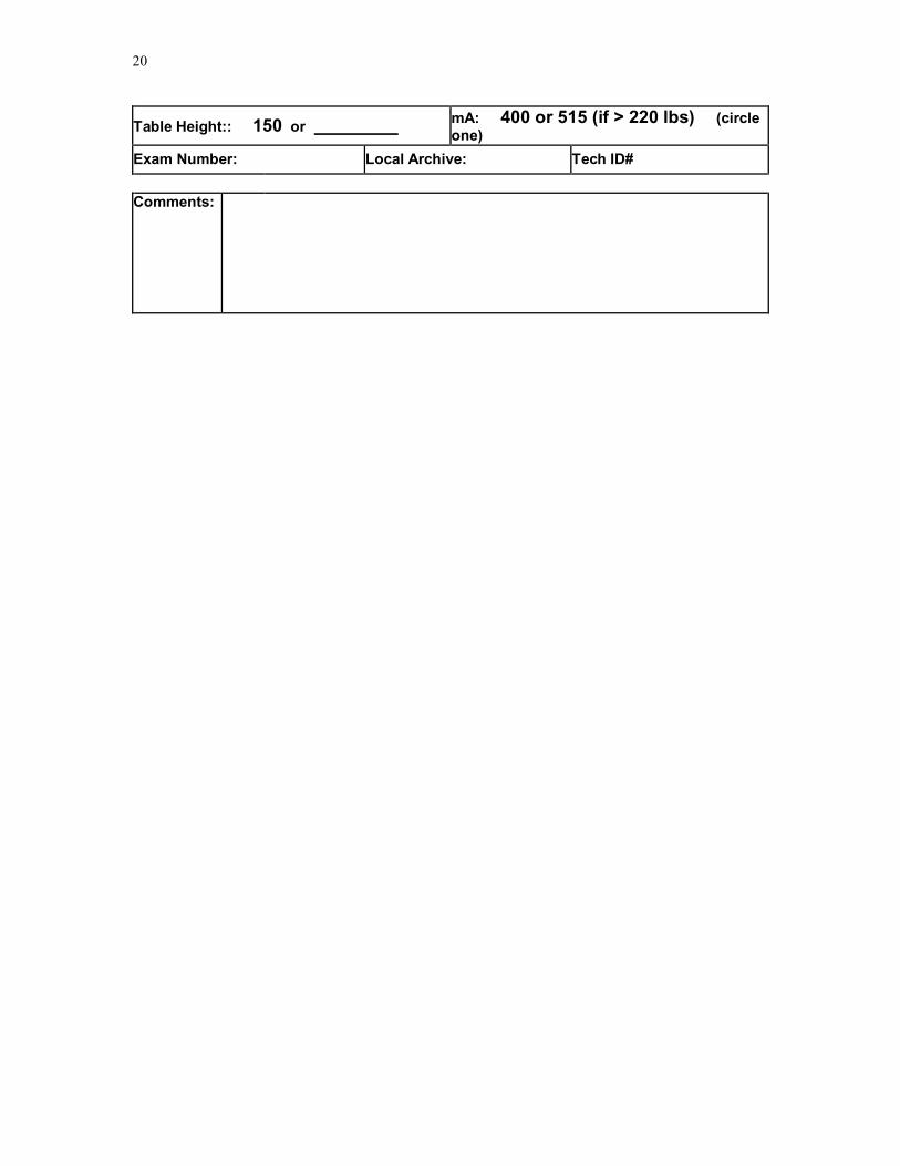
Table Height:: 150 or mA: 400 or 515 (if > 220 lbs) (circle one)
Exam Number: Local Archive: Tech ID#
Comments:

JHS Manual 8_V 1.0 01302007
21
Appendix C Appendix C: The CT Technical Parameters for each CT system
System Mode FOV Multi s lice Kernel / r econ
time ECG g ating
GE LightSpeed 16 Pro
Axial/CI NE
35 cm 8 slice by 2.5 mm
Std / P artial 0.5 s Prospective 70%
Heart Scans: Adjusting mA / mAs based on Weight
System KVp Gantry speed [s]
Exposure Time [s]
Weight < 220 lbs
Weight = > 220 lbs
GE LightSpeed 16 Pro
120 0.50 s 0.33s 320 mA 106 mAs
400 mA 133 mAs
Note: The Siemens and Philips systems will enter mAs values while the GE systems will enter mA values. The appropriate value has been made bold in the above table.
CT Technical Parameter for the Abdominal Aorta Scan:
CT System Mode FOV Pitch 1 Kernel /recon
KV mA time mAs 2
GE LightSpeed Plus (WFU/MGH/UT)
Helical 35 & 50 cm
4i 3:1 HQ
Std / full
120 300 0.5 s 200 150
1 Note pitch on multidetector CT systems have been described with competing conventions by different vendors, thus for the Siemens & Marconi systems the pitch can be explained as 3:1 [7.5 mm table travel per rotation over a 2.5 mm slice collimation] or alternatively as 0.75:1 [7.5 mm table travel per rotation over a beam collimation of 10 mm (i.e. in 4 slice mode 2.5 mm x 4 = 10 mm beam collimation)]. 2 mAs for the Abdominal Aorta scan was reduced (decreasing participant exposure) in May 2002 after review of the initial images from the pilot / vanguard phase of the study.
**** During Protocol Development and Training final adjustment to scanning protocols will be made ****
Table CT Image Reconstruction Parameters Series Scan FOV Display FOV Kernel Recon. type

22
Heart 1 Large / Body / 55 cm 350 mm
500 mm (retro)
standard 240° (partial)
Abd. Aorta Large / Body / 55 cm 350 mm
500 mm (retro)
standard 360° (full)
JHS Manual 8_V 1.0 01302007
23
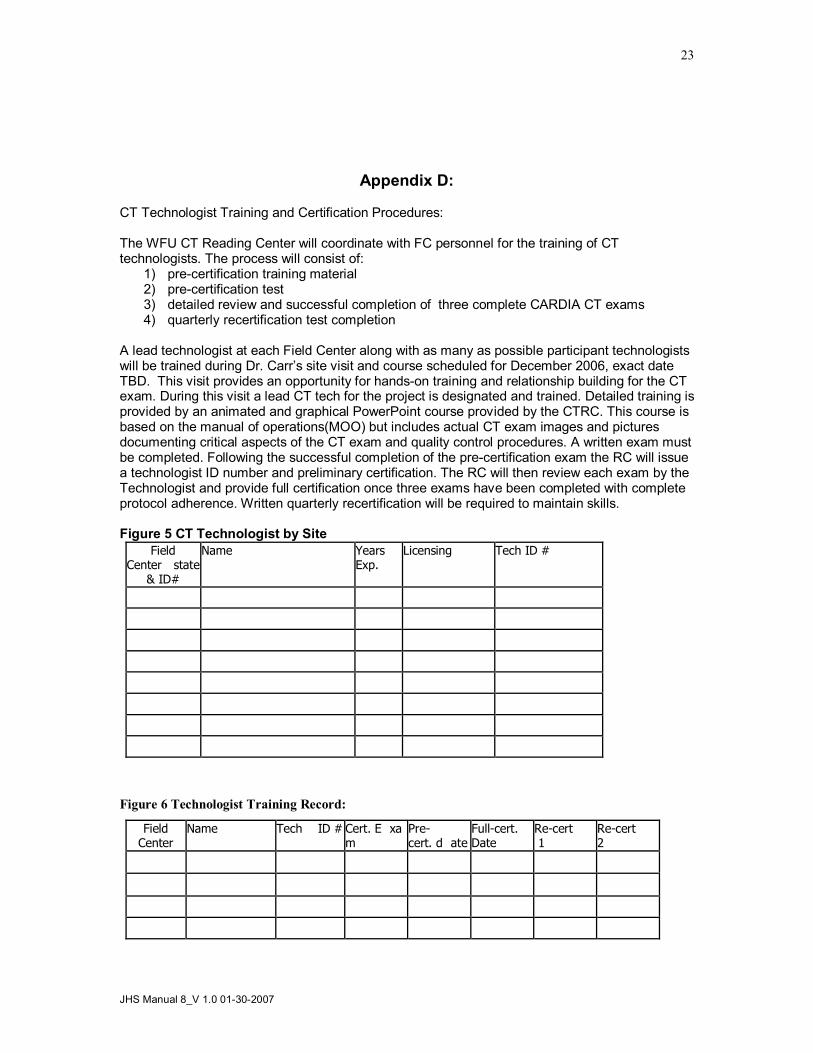
Appendix D:
CT Technologist Training and Certification Procedures:
The WFU CT Reading Center will coordinate with FC personnel for the training of CT technologists. The process will consist of:
1) precertification training material 2) precertification test 3) detailed review and successful completion of three complete CARDIA CT exams 4) quarterly recertification test completion
A lead technologist at each Field Center along with as many as possible participant technologists will be trained during Dr. Carr’s site visit and course scheduled for December 2006, exact date TBD. This visit provides an opportunity for handson training and relationship building for the CT exam. During this visit a lead CT tech for the project is designated and trained. Detailed training is provided by an animated and graphical PowerPoint course provided by the CTRC. This course is based on the manual of operations(MOO) but includes actual CT exam images and pictures documenting critical aspects of the CT exam and quality control procedures. A written exam must be completed. Following the successful completion of the precertification exam the RC will issue a technologist ID number and preliminary certification. The RC will then review each exam by the Technologist and provide full certification once three exams have been completed with complete protocol adherence. Written quarterly recertification will be required to maintain skills.
Figure 5 CT Technologist by Site Field
Center state & ID#
Name Years Exp.
Licensing Tech ID #
Figure 6 Technologist Training Record:
Field Center
Name Tech ID # Cert. E xa m
Pre cert. d ate
Fullcert. Date
Recert 1
Recert 2

24
Field Center
Name Tech ID # Cert. E xa m
Pre cert. d ate
Fullcert. Date
Recert 1
Recert 2