CT Quality Control for CT Scanners. Quality Control in CT A good idea? Yes Required for...
22
CT Quality Control for CT Scanners
-
Upload
elwin-mcbride -
Category
Documents
-
view
223 -
download
3
Transcript of CT Quality Control for CT Scanners. Quality Control in CT A good idea? Yes Required for...
CT
Quality Control for CT
Scanners
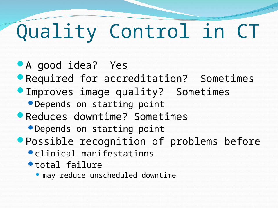
Quality Control in CT
A good idea? YesRequired for accreditation? SometimesImproves image quality? Sometimes
Depends on starting pointReduces downtime? Sometimes
Depends on starting pointPossible recognition of problems before
clinical manifestationstotal failure
may reduce unscheduled downtime

High Contrast ResolutionBaseline established when scanner in good
operating conditionSubsequent test compared to baseline

CT Quality ControlStandard protocol required
same kVp, mAs, scan diameter, slice width, algorithm, focal spot, filter, etc
When performedAt regular intervalsAfter major service
tube change
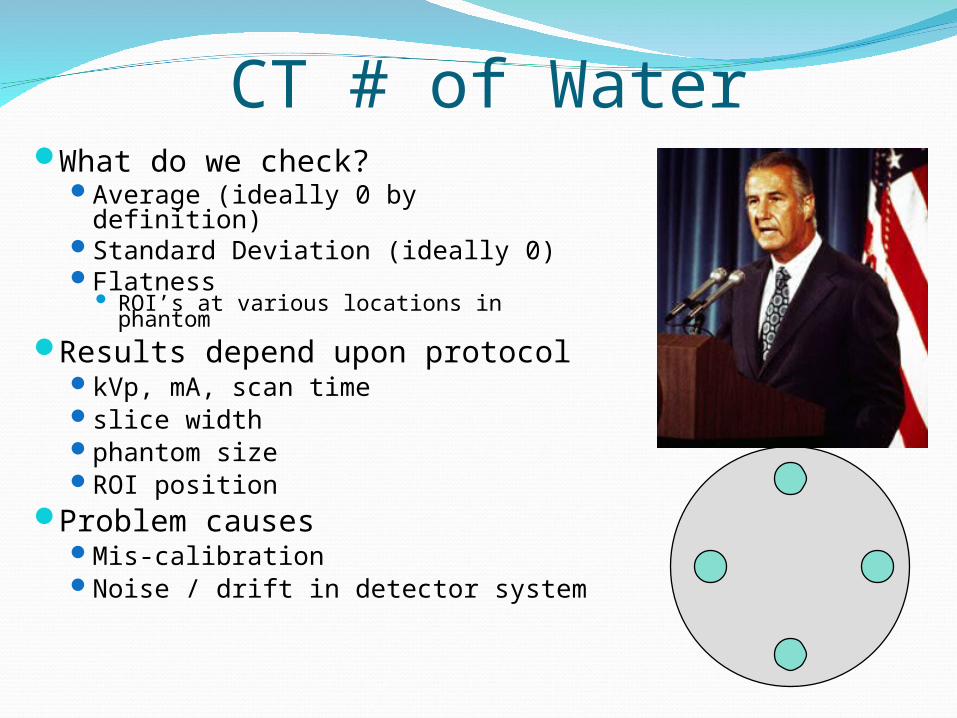
CT # of WaterWhat do we check?
Average (ideally 0 by definition)Standard Deviation (ideally 0)Flatness
ROI’s at various locations in phantom
Results depend upon protocolkVp, mA, scan timeslice widthphantom sizeROI position
Problem causesMis-calibrationNoise / drift in detector system

CT # of WaterCan repeat for various
Slice thicknessesReconstruction algorithmsCentering positionsPhantom diametersFields of view

CT Number AccuracyPhantom with several materials of known CT #’sDo ROI’s at each and check CT # accuracy
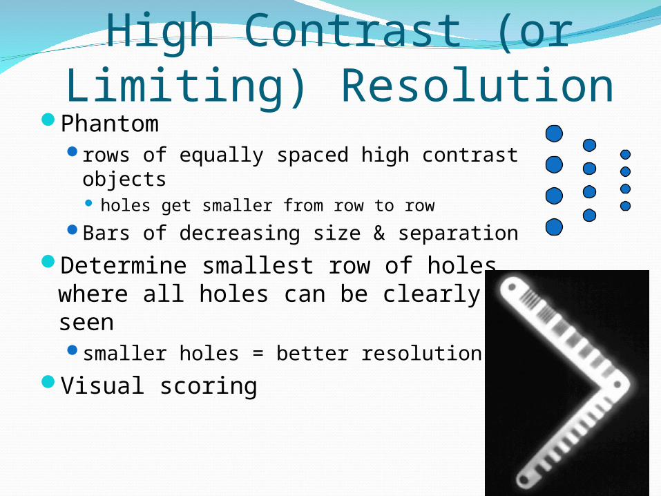
High Contrast (or Limiting) Resolution
Phantomrows of equally spaced high contrast
objects holes get smaller from row to row
Bars of decreasing size & separation
Determine smallest row of holes where all holes can be clearly seensmaller holes = better resolution
Visual scoring
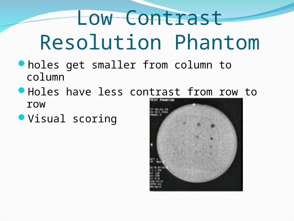
Low Contrast Resolution Phantom
holes get smaller from column to columnHoles have less contrast from row to rowVisual scoring
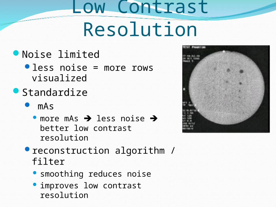
Low Contrast ResolutionNoise limited
less noise = more rows visualized
Standardize mAs
more mAs less noise better low contrast resolution
reconstruction algorithm / filter smoothing reduces noise improves low contrast resolution
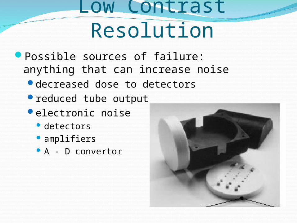
Low Contrast ResolutionPossible sources of failure: anything that
can increase noisedecreased dose to detectorsreduced tube outputelectronic noise
detectors amplifiers A - D convertor
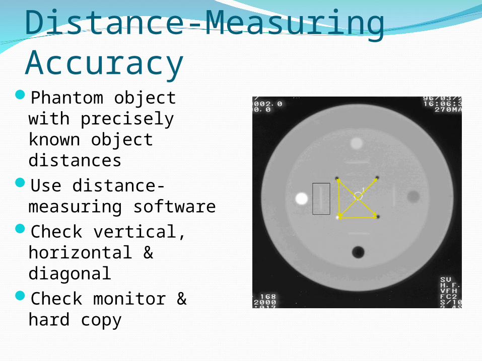
Distance-Measuring AccuracyPhantom object with
precisely known object distances
Use distance-measuring software
Check vertical, horizontal & diagonal
Check monitor & hard copy
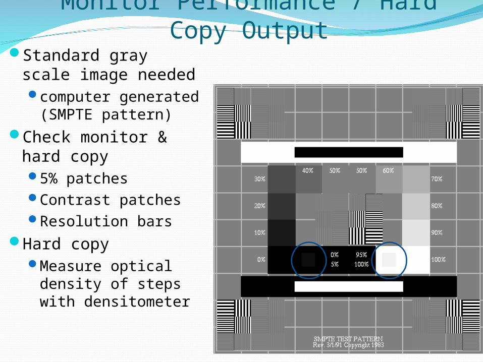
Monitor Performance / Hard Copy OutputStandard gray scale
image neededcomputer generated
(SMPTE pattern)Check monitor &
hard copy5% patchesContrast patchesResolution bars
Hard copyMeasure optical
density of steps with densitometer
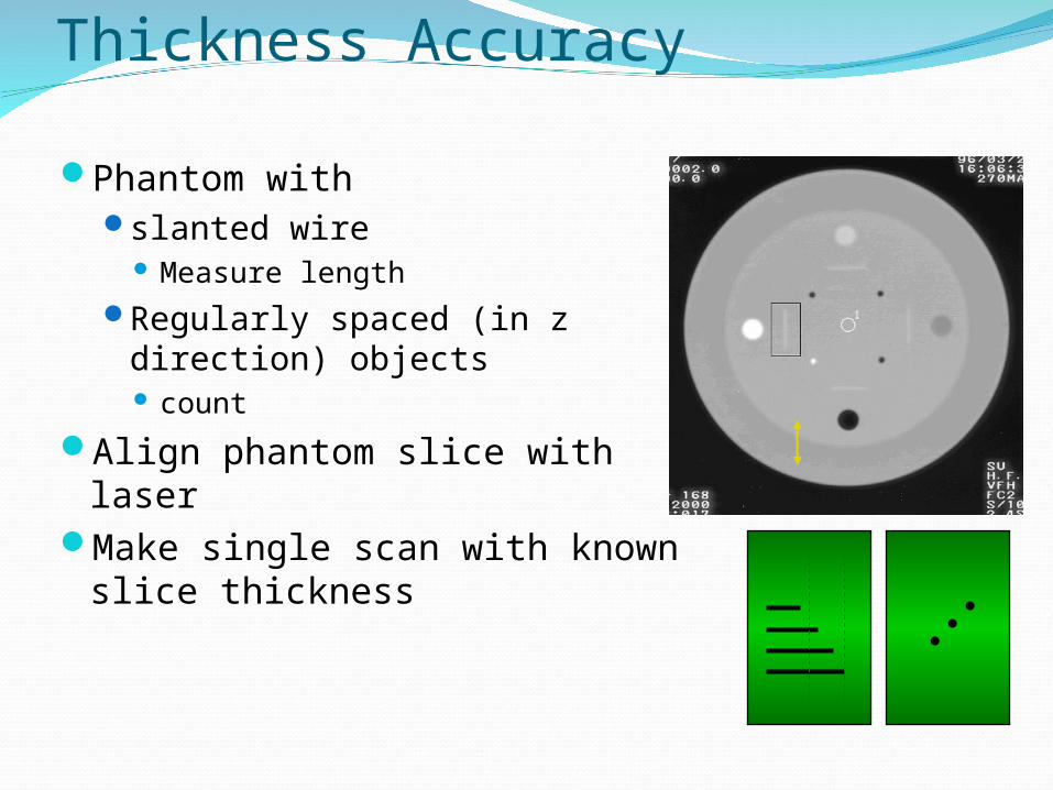
Slice Localization / Thickness Accuracy
Phantom withslanted wire
Measure lengthRegularly spaced (in z
direction) objects count
Align phantom slice with laserMake single scan with known
slice thickness
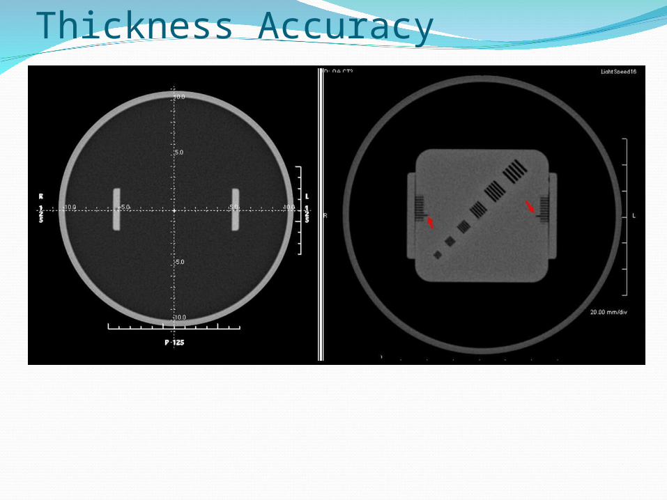
Slice Localization / Thickness Accuracy
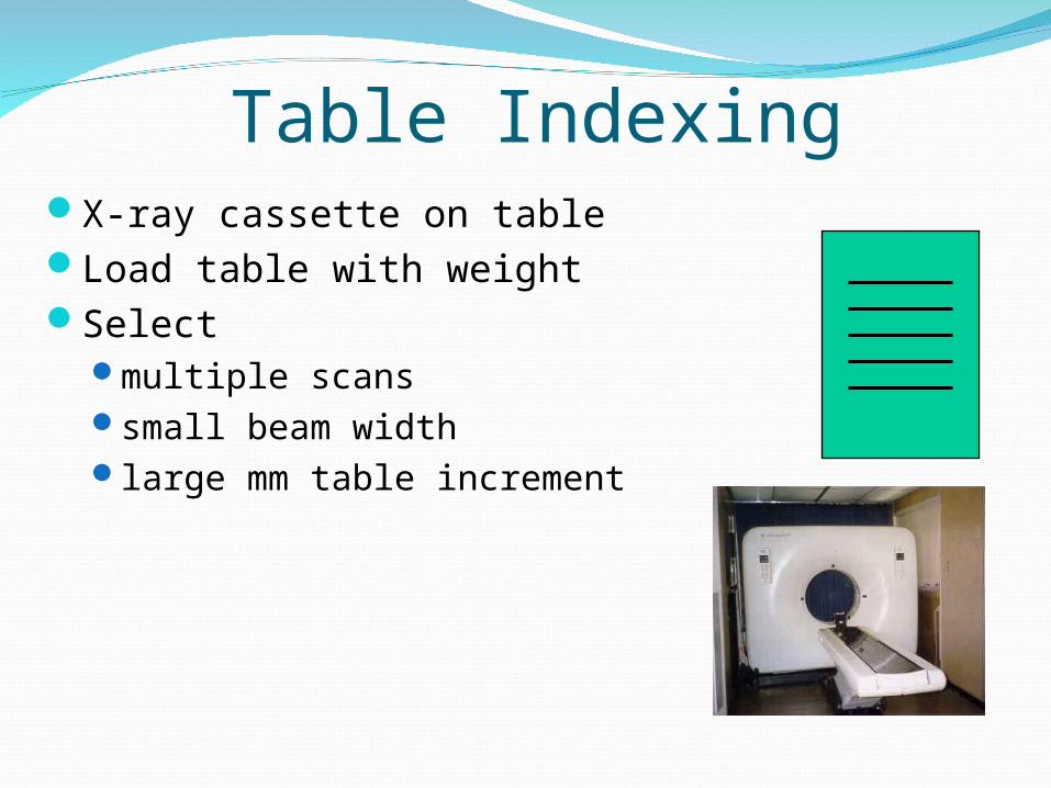
Table IndexingX-ray cassette on tableLoad table with weightSelect
multiple scanssmall beam widthlarge mm table increment
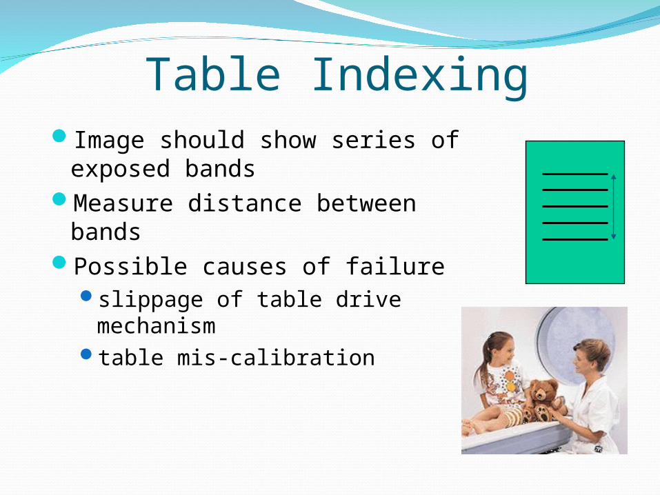
Table IndexingImage should show series of
exposed bandsMeasure distance between
bandsPossible causes of failure
slippage of table drive mechanism
table mis-calibration
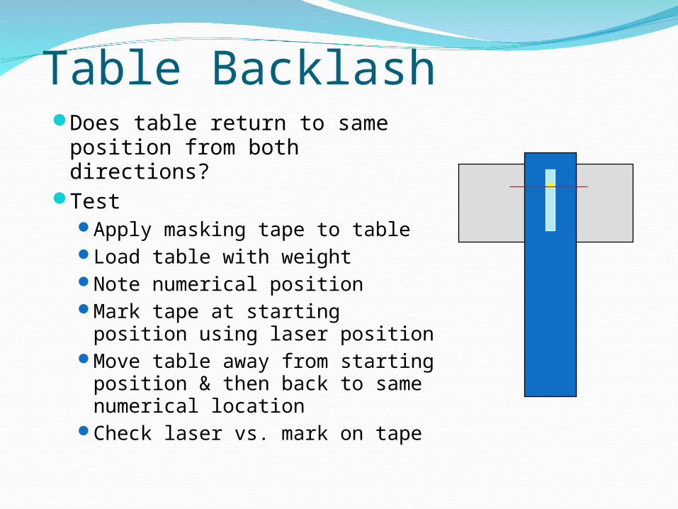
Table BacklashDoes table return to same
position from both directions?Test
Apply masking tape to tableLoad table with weightNote numerical positionMark tape at starting position
using laser positionMove table away from starting
position & then back to same numerical location
Check laser vs. mark on tape

Laser AccuracyAlign phantom on
table matching outer laser to external marks on phantom
“Zero” tableScan phantom
“0” z-location should show correct phantom position on image
Repeat for internal laser

CT Noise CharacteristicsWater phantomMultiple scans changing only mAsMeasure standard deviation of CT #’s
using identical ROI’sNoise proportional to standard deviation
CT Noise Characteristics
Excessive noise can be caused bydetector problemselectronic noise in detector amplifier circuitsreduced output per mAs