Line manager VAMP 259 for distance and line differential ...

CSP1-L Cable and Line Differential Protection SystemPerformance and functional outline
SYSTEM LINE
SCADA
Operation and display via CMP1
Data, FO
Data, FO
CSP1-L Cable and Line Differential Protection
Operation and display viaNotebook
Operation and display via CMP1
CA
N-B
US
CA
N-B
US
FO RS 2
32
(in
pre
para
tion)
FO
CSP1-L Cable and Line Differential Protection
RS 2
32

2 LF CSP1-L 06.99 E

LF CSP1-L 06.99 E 3
Contents
1 Outline and Applications .............................................................................................42 CSP1-L � digital, phase-selective differential protection ................................................5
2.1 Scope of capacity and functions ............................................................................................... 52.2 Design ................................................................................................................................. 62.3 Protection functions ................................................................................................................. 82.4 Controlling and Monitoring ...................................................................................................... 82.5 Measuring functions .............................................................................................................. 102.6 Statistical measuring values .................................................................................................... 102.7 Data recording .................................................................................................................... 11
2.7.1 Event recorder ............................................................................................................... 112.7.2 Fault recorder ................................................................................................................ 112.7.3 Disturbance recorder (optional) ......................................................................................... 11
3 CMP1 ........................................................................................................................123.1 Operating the CMP1-2 ......................................................................................................... 123.2 Operating elements of the CMP1-2.......................................................................................... 133.3 Functions of the operating elements.......................................................................................... 133.4 Programming & Parameter Setting............................................................................................ 14
4 SYSTEM-LINE-SOFT .....................................................................................................154.1 Scope of functions and performance ........................................................................................ 15
5 Technical Data ...........................................................................................................185.1 Auxiliary voltage .................................................................................................................. 18
5.1.1 Voltage supply CMP1..................................................................................................... 185.1.2 Voltage supply CSP1 ...................................................................................................... 18
5.2 Measuring inputs .................................................................................................................. 195.2.1 Current inputs ................................................................................................................ 195.2.2 Voltage inputs (optional in CSP1-L)..................................................................................... 195.2.3 Measuring precision ....................................................................................................... 20
5.3 Function and signal inputs ...................................................................................................... 205.4 Outputs .............................................................................................................................. 21
5.4.1 Power outputs ................................................................................................................ 215.4.2 Signal relays ................................................................................................................. 22
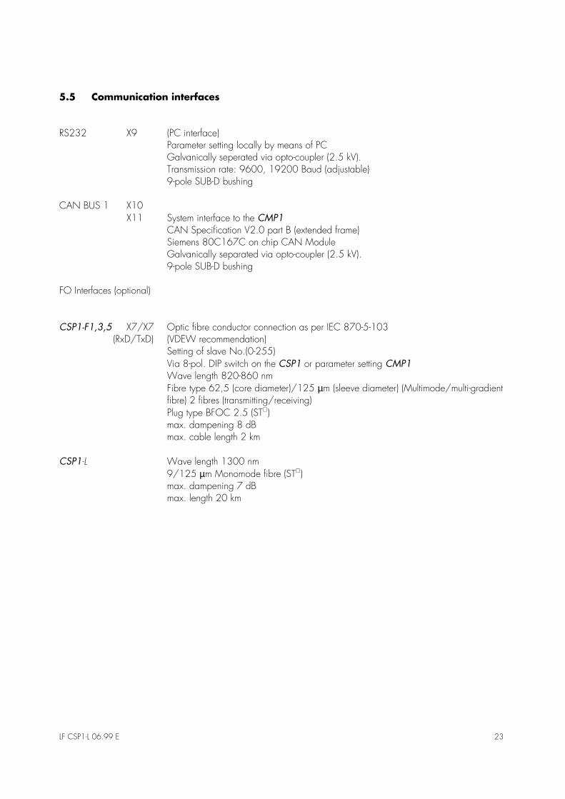
5.5 Communication interfaces ...................................................................................................... 235.6 Standards ........................................................................................................................... 24
5.6.1 General regulations ........................................................................................................ 245.6.2 High-voltage tests (EN 60255-6 [11.94]) .......................................................................... 245.6.3 EMC Emission test I ........................................................................................................ 245.6.4 EMC Emission test II........................................................................................................ 255.6.5 Mechanical stress........................................................................................................... 255.6.6 Climatic stress................................................................................................................ 255.6.7 Dimensions and weights .................................................................................................. 26
6 Order Form ...............................................................................................................27

4 LF CSP1-L 06.99 E
1 Outline and Applications
The top-quality digital protection and control sytems ofthe »SYSTEM LINE« fulfil all demands and requirementsfor protection and control at medium-voltage level.
Pro
tect
ion r
equir
em
ents
Functionality
SYSTEM LINE
CSP1-B
Busbar protection
CSP1-L
Line/cable differentialprotection
CSP1-F
Feeder management
Figure 1.1: Range of SYSTEM-LINE devices
The line differential protection system CSP1-L is a fast,phase-selective cable and line differential protectionsystem.
Development work focussed primarily on the followinggoals:
•� User-friendly operation,•� Flexibility,•� Ease of integration into switchboards,•� Freely selectable functions,•� Large range of applications and•� Standardized communication.
� Cost optimization at the medium-voltage level
CSP1-L
CMP1-2
SYSTEM 1 SYSTEM 2
CSP1-L
CMP1-2
FO
)2
Cable/Line
Figure 1.2: Block diagramm
The differential protection systems at both ends of theobjects to be protected each consist of two separatedevices, i.e. the base unit CSP1-L and the operatingand display unit CMP1
•� In the CSP1-L, which is capable of working self-suffiently, all protection functions are integrated.The base unit is installed into the low-voltage niche(mounted on mounting plate). The wide-range po-wer part permits connection of all aux. voltage e-quipment commonly used in MV systems.
� One device for all switchgears and applications
The compact operating and display unit CMP1 is de-centralilzed and installed in the front door of the circuitbreaker panel. The simple, menu-guided operation,the large display with illuminated background as wellas the ergonomically designed surface ensure fast andcomprehensive information of the operating personnelat all times. A single bus/line replaces the conventio-nal cable tree.
SCADA
Data, FO
Operation and display viaNotebook
Operation and display via CMP1
CA
N-B
US
RS 2
32 (i
n pr
epar
atio
n)
FO
RS 2
32
CSP1-L Cable and Line Differential Protection
Data, FO
Figure 1.3: CSP1-L Cable and Line Differential Protection System

LF CSP1-L 06.99 E 5
2 CSP1-L � digital, phase-selective differential protection
The base module CSP1-L, which is capable of working self-sufficiently, comprises the complete protection tech-nology.
DIP-SWITCHES DIGITAL INPUTSAUX.VOLTAGE
SUPPLY
LEDs
SIGNAL RELAY
CONTROL
OUTPUTS
CURRENT
INPUTS
Figure 2.1: CSP1-L
2.1 Scope of capacity and functions
The base unit CSP1-L features the following special characteristics:
•� Compact design in robust aluminium/plastic housing in accordance with protection class IP50,•� Wide-range power part,•� Wide range of protection and control functions,•� Flexible management of inputs and outputs,•� Power outputs directly driving the circuit breaker,•� Communication with host computers via VDEW-interface with fibre optic conductor (optional)
(as per IEC 870-5-103),•� Various communication interfaces: CAN-Bus, RS232 for parameter setting,•� Highly efficient fault recording function (optional),•� Comprehensive self-monitoring and•� No maintenance required.
6 LF CSP1-L 06.99 E
MEDIUM VOLTAGE PANEL
CSP1-L Cable and LineDifferential Protection System
Supervision
Signal/indication
Statistics
Measurement
Disturbancerecorder
Protection
Notebook
Communication
SUBSTATION CONTROL SYSTEMMASTER SYSTEM
RS 232optional
CMP1-2 PARTNER DEVICE
Display
CSP1-L PARTNER DEVICE
FO
CAN-BUS )2
Input Output
RS 232
&$1�%86
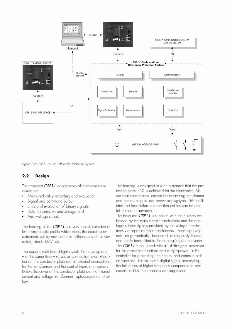
Figure 2.2: CSP1-L as Line Differential Protection System
2.2 Design
The compact CSP1-L incorporates all components re-quired for:•� Measured value recording and evaluation,•� Signal and command output,•� Entry and evaluation of binary signals,•� Data transmission and storage and•� Aux. voltage supply.
The housing of the CSP1-L is a very robust, extruded a-luminium/plastic profile which meets the exacting re-quirements set by environmental influences such as vib-ration, shock, EMV, etc.
The upper circuit board tightly seals the housing, and� at the same time � serves as connection level. Moun-ted on this conductor plate are all external connectionsfor the transformers and the control inputs and outputs.Below the cover of this conductor plate are the internalcurrent and voltage transformers, opto-couplers and re-lays.
The housing is designed in such a manner that the pro-tection class IP50 is achieved for the electronics. Allexternal connections, except the measuring transformerand control outputs, are screw- or plug-type. This facili-tates fast installation. Connection cables can be pre-fabricated in advance.The base unit CSP1-L is supplied with the currents em-bossed by the main current transformers and the ana-logous input signals provided by the voltage transfo-mers via separate input transformers. These input sig-nals are galvanically decoupled, analogously filteredand finally transmitted to the analog/digital converter.The CSP1-L is equipped with a 24-Bit signal processorfor the protection functions and a high-power 16-Bitcontroller for processing the control and communicati-on functions. Thanks to the digital signal processing,the influences of higher frequency compensation pro-cesses and DC components are suppressed.

LF CSP1-L 06.99 E 7
Figure 2.3: Connection diagramm
8 LF CSP1-L 06.99 E
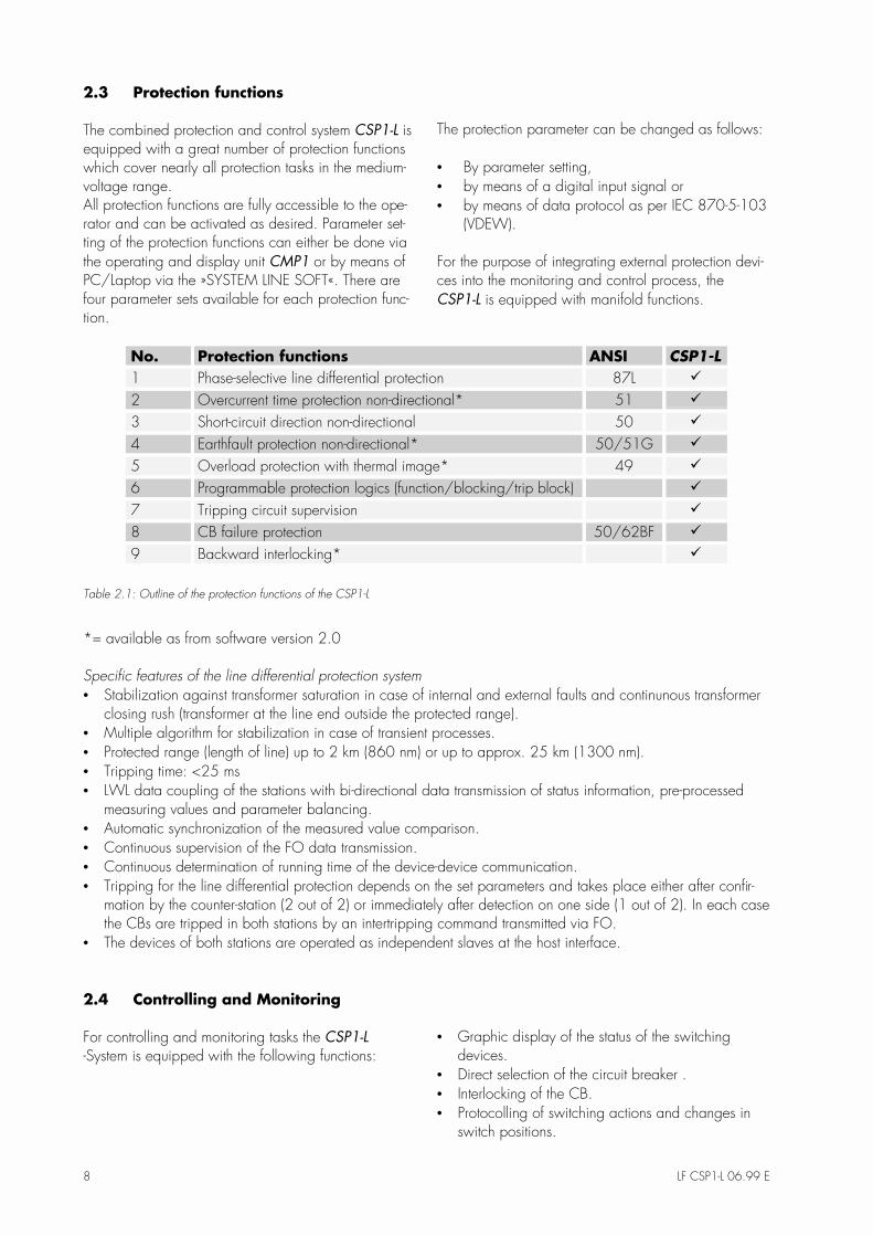
2.3 Protection functions
The combined protection and control system CSP1-L isequipped with a great number of protection functionswhich cover nearly all protection tasks in the medium-voltage range.All protection functions are fully accessible to the ope-rator and can be activated as desired. Parameter set-ting of the protection functions can either be done viathe operating and display unit CMP1 or by means ofPC/Laptop via the »SYSTEM LINE SOFT«. There arefour parameter sets available for each protection func-tion.
The protection parameter can be changed as follows:
•� By parameter setting,•� by means of a digital input signal or•� by means of data protocol as per IEC 870-5-103
(VDEW).
For the purpose of integrating external protection devi-ces into the monitoring and control process, theCSP1-L is equipped with manifold functions.
No. Protection functions ANSI CSP1-L
1 Phase-selective line differential protection 87L 9
2 Overcurrent time protection non-directional* 51 9
3 Short-circuit direction non-directional 50 9
4 Earthfault protection non-directional* 50/51G 9
5 Overload protection with thermal image* 49 9
6 Programmable protection logics (function/blocking/trip block) 9
7 Tripping circuit supervision 9
8 CB failure protection 50/62BF 9
9 Backward interlocking* 9
Table 2.1: Outline of the protection functions of the CSP1-L
*= available as from software version 2.0
Specific features of the line differential protection system•� Stabilization against transformer saturation in case of internal and external faults and continunous transformer
closing rush (transformer at the line end outside the protected range).•� Multiple algorithm for stabilization in case of transient processes.•� Protected range (length of line) up to 2 km (860 nm) or up to approx. 25 km (1300 nm).•� Tripping time: <25 ms•� LWL data coupling of the stations with bi-directional data transmission of status information, pre-processed
measuring values and parameter balancing.•� Automatic synchronization of the measured value comparison.•� Continuous supervision of the FO data transmission.•� Continuous determination of running time of the device-device communication.•� Tripping for the line differential protection depends on the set parameters and takes place either after confir-
mation by the counter-station (2 out of 2) or immediately after detection on one side (1 out of 2). In each casethe CBs are tripped in both stations by an intertripping command transmitted via FO.
•� The devices of both stations are operated as independent slaves at the host interface.
2.4 Controlling and Monitoring
For controlling and monitoring tasks the CSP1-L
-System is equipped with the following functions:•� Graphic display of the status of the switching
devices.•� Direct selection of the circuit breaker .•� Interlocking of the CB.•� Protocolling of switching actions and changes in
switch positions.

LF CSP1-L 06.99 E 9
The switching device positions are recorded via twoopto-decoupled inputs each for »OFF« and »ON« onthe CSP1-L. The position signals of the various swit-ching devices (up to 3) are shown on the LC graphicdisplay of the CMP1 in the form of a single-line. Faultand differential positions are indicated by a dottedswitching symbol in centre position. The single linediagram is pre-set at the factory in accordance withcustomer requirements. It can be easily adjusted tospecific applications thanks to a configuration soft-ware. In addition to status recording it is possible torecord, protocol and transmit external protection sig-nals, monitoring messages, external control commandsand interlocking functions with varying functionalitiesvia the freely adjustable inputs.
Q0
Q9
Q8
Figure 2.4: Example Feeder Configuration
In addition to the functional assignments, it is also pos-sible to set parameters for rebouncing time and signallogics for each input.
By means of potential-free signal relays it is possible totransmit binary signals for protection and monitoring(e.g. CB failure, backward interlocking).
CB = Circuit Breaker
No. Control functions CSP1-L
1 Number of controllable switching devices 1
2 Number of recordable switching devices displayable on the graphic display 3
3 Number of power outputs for changing the switch position (coil selection) of circuit brea-kers
2
4 Number of signal relays 6
5 Number of digital inputs with freely settable parameters 8
6 Command output with defined output and extra running times 9
No. Supervision functions CSP1-L
7 Disturbance/diff. position 9
8 CB removed 9
9 Spring tensioned 9
10 Programmable feeder interlocking 9
Table 2.1: Outline of control and supervision functions of the CSP1-L

10 LF CSP1-L 06.99 E
2.5 Measuring functions
In addition to the recorded measuring values currentand voltage, further measuring values such as activeand reactive power etc. are calculated and displayedas primary values. The measured values can be called
up cyclically and transmitted via the CMP1, a laptopor a PC, or via communication with the host computer.The measuring error rate is < 1% in the operating ran-ge and up to 40 x IN < 3%.
No. Measuring functions CSP1-L
1 Phase currents IL1, IL2, IL3 9
2 Earth current IE 9
3 Differential current 9
4 Stabilising current 9
5 Harm. stabilisation factor 9
6 Thermal capacity 9
7 Time up to overload tripping 9
Table 2.2: Outline of measuring functions of the CSP1-L
2.6 Statistical measuring values
In addition to measuring value recording, the CSP1-L
offers statistical functions. Maximum und average va-lue as well as counting functions can be called up viathe CSP1-L.
The maximum and average values can be called upvia a variable time window. The counting functionssuch as operating hours or switching cycle counter areresettable.
No. Statistical data CSP1-L
1 Max. current value 9
2 Mean current value 9
3 Number of operating cycles per switching device 9
4 Sum total of switched short-circuit currents 9
5 Operating data 9
6 Max. differential current 9
7 Mean differential current 9
8 Max. stabilisation current 9
9 Mean stabilisation current 9
Table 2.3: Statistical data (available as from software version 2.0)

LF CSP1-L 06.99 E 11
2.7 Data recording
The CSP1-L offers various protocolling and recordingmethods for events, fault values and fault records,which are stored in the CSP1-L and can be called upvia the CMP1, a PC or the communication interface.This way, the operator has all data for fault analysisand fault elimination locally at his disposal.
2.7.1 Event recorder
The event recorder protocols and stores the last 50 e-vents in the CSP1-L. The recorded messages are filedwith running number and real time stamp, safe againstdevice failure, in a non-volatile memory. Each event isstored with date, time, cause, event and informationwith a resolution of 1 ms. This includes all messageswhich are related to protection, control, the configu-rable inputs, parameter setting and internal system su-pervision of the device. In case of a fault, the protecti-on messages are additionally marked with a clear anddefinite failure case number.
2.7.2 Fault recorder
The fault recorder stores the last 5 faults failure-safe inthe CSP1-L in accordance with the failure case num-ber. In addition to the triggering event, all effectivemeasuring values as stored and displayed as primaryvalues. In case of damage, this permits evaluation andanalysis at a later date by means of the protectionmessages stored in the event recorder.
2.7.3 Disturbance recorder (optional)
The analogous and digital information is stored in thedisturbance recorder for the purpose of evaluatingmains interferences. Up to 8 digitalized measuring va-lues (phase currents, earth current, conductor voltages,residual voltage) are recorded. Simultaneously, binaryinput and output signals can be recorded. The maxi-mum recording time amounts to 10 s, with a pre-running and extra running time being adjustable. Themeasured values are recorded in the form of momen-tary values.

12 LF CSP1-L 06.99 E
3 CMP1
The CMP1 is easy to operate and ergonomicallydesigned. The CMP1 is installed in the front door ofthe medium-voltage compartment as separate opera-ting and control unit. It informs the operating personnelabout the momentary status of the feeder and controlsthe circuit breaker connected to the CSP1-L. A singlecable establishes the connection to the base unitCSP1-L and thus replaces the conventional cable tree.This cable can be easily laid jointly with the aux. vol-tage supply.
Figure 3.1: CMP1-2
The most significant features of the CMP1 include:
•� Flat, compact design,•� Wide-range voltage supply,•� Large LC graphic display with illuminated back-
ground (128 x 240 Pixel),•� Foil keyboard as per protection class IP54,•� Multi-coloured function keys for menu guidance,•� Two key switches for fixing the various switching
authorizations,•� 11 multi-coloured LEDs (8 freely configurable),•� Two RS232 interfaces for parameter setting and
readout of data via PC.
The large LC-graphic display permits:
•� Display of a freely configurable single line dia-gram.
•� Display of switch positions, measuring values andoperating instructions.
•� Protocolling of events with real-time stamp.•� Protocolling of interference events with effective
values.•� Comprehensive commissioning support and mani-
fold testing possibilities.
3.1 Operating the CMP1-2
Parameter setting can be effected via the CMP1. Allentries are made via the foil keyboard. Check-backsand status indications are shown on the large graphicdisplay with illuminated background. The displayshows switch positions graphically, messages as textsand parameters or measured values in table form.
LF CSP1-L 06.99 E 13
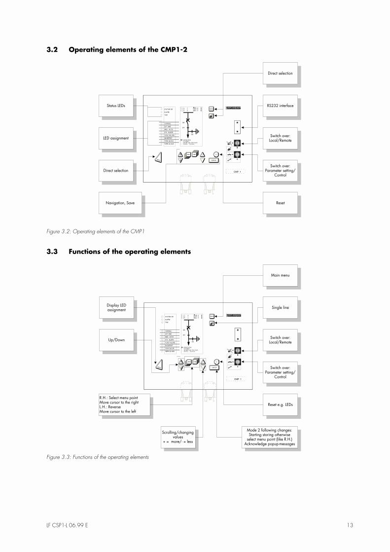
3.2 Operating elements of the CMP1-2
Direct selection
RS232 interface
Switch over:Local/Remote
ResetNavigation, Save
LED assignment
Status LEDs
Direct selectionSwitch over:
Parameter setting/Control
Figure 3.2: Operating elements of the CMP1
3.3 Functions of the operating elements
Display LEDassignment
Single line
R.H.: Select menu pointMove cursor to the rightL.H.: ReverseMove cursor to the left
Up/Down
Scrolling/changingvalues
+ = more/- = less
Main menu
Switch over:Local/Remote
Reset e.g. LEDs
Switch over:Parameter setting/
Control
Mode 2 following changes:Starting storing otherwise
select menu point (like R.H.)Acknowledge popup-messages
Figure 3.3: Functions of the operating elements

14 LF CSP1-L 06.99 E
3.4 Programming & Parameter Setting
There are 4 complete parameter sets available for theprotection functions. Thus it is possible to select, setparameters and switch over between four protectionparameter sets. There is always one of the four para-meter sets active or in operation.Each parameter set can be edited in the backgroundand stored at the end without influencing the activelyoperating protection and control functions. A changedparameter set, even if only one single parameter hasbeen changed, will only become active upon confir-mation of the storing function (acknowledgement). Thefundamental parameter set serves to fix the basic con-figuration of the device such as rated feeder data,control times, configuration of the inputs and outputsand communication.Locally, parameter setting of the CSP1-L can be effec-ted menu-guided via the operating surface of theCMP1 or by means of a PC via the serial interface.

LF CSP1-L 06.99 E 15
4 SYSTEM-LINE-SOFT
Operating and evaluation programme/Functions
The software for setting the parameters of the CSP1-L
via PC and interface is still in preparation.
The »System-Line-Soft« permits evaluation and para-meter setting of the CSP1 family of devices. It willwork on any PC with the operating systems Windows95/98 or Windows NT. Communication takes placevia the RS232 interface or via the internal CAN-BUS.It permits operation by the use of the mouse (Windowssurface) and has a user-guided window technology.The »System-Line-Soft« is easy to instal and is availablein different languages.
4.1 Scope of functions and performance
•� Available for all devices of the »System Line«,•� Setting of parameters for all device-specific data,•� Window technology with operating and status
line,•� Menu-guided plausibility checks,•� Comprehensive help functions,•� Readout, readin, comparison with the device pos-
sible,•� Archiving, editing such as copying or erasing da-
ta sets,•� Logbook function,•� Readout of messages,•� Cyclic readout of measured values,•� Further processing of measured values (recording,
displaying),•� Controlling possible with single line diagram
display,•� Query to inputs and outputs,•� Commissioning support (e.g. diff- und stability va-
lues in case of DIFF), fundtional support as well asVDEW-Test,
•� Evaluation of fault records, curve-type illustration,editability, additional information such as Trigger,
•� Initiation of test fault records and•� Time synchronization from the PC.
LAPTOP
RS 232
CAN-BUS
RS 232 (in Vorbereitung)
Figure 4.1: Connection example CSP1-L/CMP1-PC via RS 232

16 LF CSP1-L 06.99 E
Figure 4.2: Display event recorder
Figure 4.3: Display fault recorder
LF CSP1-L 06.99 E 17
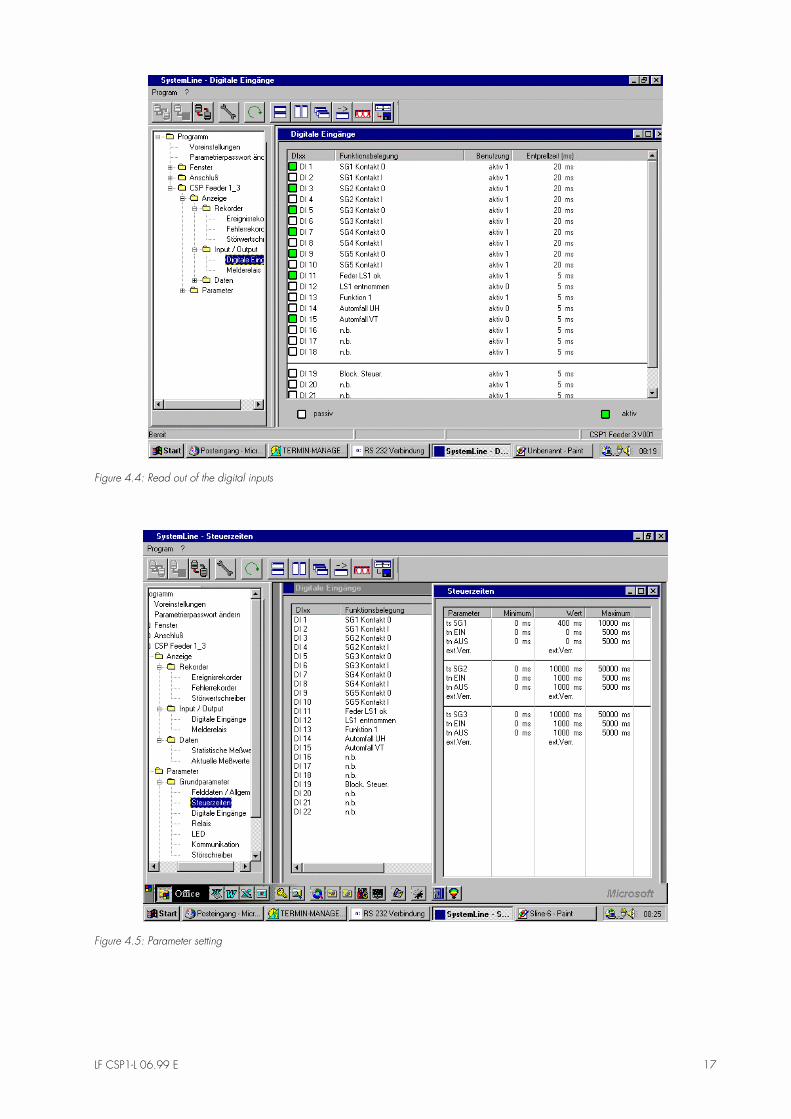
Figure 4.4: Read out of the digital inputs
Figure 4.5: Parameter setting

18 LF CSP1-L 06.99 E
5 Technical Data
5.1 Auxiliary voltage
5.1.1 Voltage supply CMP1
Voltage ranges Power consumption in idle state Max. power consumption19 - 395 VDC 5 W 10 W22 - 280 VAC 5 VA 10 VA
Frequency range f = 40-70 Hz
5.1.2 Voltage supply CSP1
Voltage ranges Power consumption in idle state Max. power consumption19 - 395 VDC 14 W 26 W22 - 280 VAC 14 VA 26 VA
Frequency range f = 40-70 Hz
Fixed aux. voltages (EN 60255-6):
DC 24 V, 48 V, 60 V, 110 V, 220 VAC 24 V, 100 V, 110 V, 230 V
The power supply part furthermore covers the following commonly used aux. voltages (among others in the UK)with limited tolerance ranges:
240 VAC with the tolerance range -20% / +15%254 VAC with the tolerance range -20% / +10%
The permissible voltage deviations refer to the fixed rated aux. voltages.
Buffering of the aux. voltage supply:= 50 ms at Uemin.
In case of aux. voltage failure functioning of the device is ensured for at least 50 ms.
The fuse for the aux. voltage supply (230) must be dimension min. 4 A, lag.

LF CSP1-L 06.99 E 19
5.2 Measuring inputs
5.2.1 Current inputs
Quantity: 3 phase currents + 1 summing current (for earth, e.g. cable-type CT)
Measuring method: conventional transformers (other sensors in preparation)
Rated currents: 1 A and 5 A
Connectionsper current input: 3 (1S1(1 A), 1S2(5 A), 1S3)
Measuring range: 0...40 x IN (AC) phase currents0...20 x IN (AS) summing current
Power consumptionin the power path: = 0.1 VA at I = IN
Thermal load capacity:Rated peak short-circuitcurrent: 250 x IN (dynamic half period of sinus oscillation)
Rated short-term current 100 x IN (for 1 s)
Permanent load capacity: 4 x IN
5.2.2 Voltage inputs (optional in CSP1-L)
Quantity: 3 x phase voltage (P-P, P-N) +1 x residual voltage
Measuring method: conventional transformers(other sensors in preparation)
Rated voltages: 100, 110 VAC
Connections per voltageinput: 2 (1A1, 1A2)
Measuring range: 0...230 VAC
Thermal load capacity: 2 x UN permanent load capacity
Power consumption: = 0.1 VA at U = 230 V
Rated frequencies: 50 Hz; 60 Hz (parameter adjustable)

20 LF CSP1-L 06.99 E
5.2.3 Measuring precision
Current (at rated frequency): 0.1 � 1.5 x IN < 1% of IN1.5 - 40 x IN< 3% of Measured value
Frequency influence: < 2% / Hz
Voltage in relation to rated voltage(at rated frequency): 10 - 50 V < 2%
50 - 220 V ...< 1%
Frequency influence: < 2% / Hz
Frequency: 40 - 70 Hz < 0.05%
Power: PN < 2%
5.3 Function and signal inputs
Opto-decoupler inputs
Quantity: 14 (CSP1-F1)22 (CSP1-F3)26 (CSP1-F5)14 (CSP1-L)
Input voltage range: 0 - 350 VDC
0 - 270 VAC
Threshold value recognition:low set range: Uon = 8.5 VDC/8.5 VAC (50/60 Hz)(code plug plugged in) Uoff = 5.5 VDC/4.5 VAC (50/60 Hz)high set range: Uon = 35 VDC/35 VAC (50/60 Hz)(code plug open) Uoff = 20 VDC/19 VAC (50/60 Hz)
Input current: < 2 mADC (depending on input voltage)< 2 mAAC (depending on input voltage)
Adjustable rebouncingtime: 0 ...100 ms per dig. input
(1 ms pitch)
LF CSP1-L 06.99 E 21
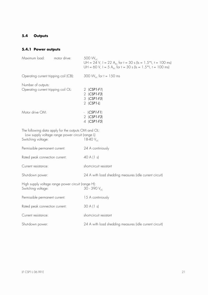
5.4 Outputs
5.4.1 Power outputs
Maximum load: motor drive: 500 WDC
UH = 24 V, I = 22 ADC for t = 30 s (Is = 1.5*I, t = 100 ms)UH = 60 V, I = 5 ADC for t = 30 s (Is = 1.5*I, t = 100 ms)
Operating current tripping coil (CB): 300 WDC for t = 150 ms
Number of outputs:Operating current tripping coil OL: 2 (CSP1-F1)
2 (CSP1-F3)3 (CSP1-F5)2 (CSP1-L)
Motor drive OM: - (CSP1-F1)2 (CSP1-F3)4 (CSP1-F5)
The following data apply for the outputs OM and OL: Low supply voltage range power circuit (range L)Switching voltage: 18-40 VDC
Permissible permanent current: 24 A continiously
Rated peak connection current: 40 A (1 s)
Current resistance: short-circuit resistant
Shut-down power: 24 A with load shedding measures (idle current circuit)
High supply voltage range power circuit (range H):Switching voltage: 30 - 390 VDC
Permissible permanent current: 15 A continiously
Rated peak connection current: 30 A (1 s)
Current resistance: short-circuit resistant
Shut-down power: 24 A with load shedding measures (idle current circuit)

22 LF CSP1-L 06.99 E
5.4.2 Signal relays
Number: 6 CSP1-F1/F3/L, 10 CSP1-F5
Switching voltage: 250 VAC
220 VDC, ohmic load Imax. = 0.2 Ainductive load Imax. = 0.1 A L/R < 50 ms24 VDC inductive load Imax. = 5 A
Switching power: ohmic 1250 VAAC or 120 WDC, respectivelyinductive 500 VAAC or 75 WDC, respectively
Min. switching load: 18 V/2 mA
Max rated current: 5 A
Switching current: (16 ms): 20 A
Insulation: 4 kV
Contact material: AgNi + Au
Contact service life: mechanical: 100 x 10^6 operating cycle
LF CSP1-L 06.99 E 23
5.5 Communication interfaces
RS232 X9 (PC interface)Parameter setting locally by means of PCGalvanically seperated via opto-coupler (2.5 kV).Transmission rate: 9600, 19200 Baud (adjustable)9-pole SUB-D bushing
CAN BUS 1 X10X11 System interface to the CMP1
CAN Specification V2.0 part B (extended frame)Siemens 80C167C on chip CAN ModuleGalvanically separated via opto-coupler (2.5 kV).9-pole SUB-D bushing
FO Interfaces (optional)
CSP1-F1,3,5 X7/X7 Optic fibre conductor connection as per IEC 870-5-103(RxD/TxD) (VDEW recommendation)
Setting of slave No.(0-255)Via 8-pol. DIP switch on the CSP1 or parameter setting CMP1
Wave length 820-860 nmFibre type 62,5 (core diameter)/125 µm (sleeve diameter) (Multimode/multi-gradient fibre) 2 fibres (transmitting/receiving)Plug type BFOC 2.5 (ST)max. dampening 8 dBmax. cable length 2 km
CSP1-L Wave length 1300 nm9/125 µm Monomode fibre (ST)max. dampening 7 dBmax. length 20 km

24 LF CSP1-L 06.99 E
5.6 Standards
5.6.1 General regulations
Generic standard DIN EN 50082-2 [02.96]DIN EN 50081-1 [03.93]
Product standard DIN EN 60255-6 [11.94]BS 142DIN EN 50178 [04.98]
5.6.2 High-voltage tests (EN 60255-6 [11.94])
Voltage testIEC 60255-5 [01.77]DIN EN 50178 [04.98]
All electric circuits against other elect-ric circuits and touchable surfaces.
2.5 kV (eff.)/50 Hz, 1 min.
Peak-voltage testIEC 60255-5 [01.77] 5 kV/0.5 J, 1.2/50 µs
High-frequency testDIN EN 60255-22-1[05.91]Class 3
Within a electric circuitElectric circuit against earthElectric circuit against electric circuit
1 kV/2 s2.5 kV/2 s2.5 kV/2 s
5.6.3 EMC Emission test I
Disturbance resistance against fast transient disturbance values (Burst)DIN IEC 60255-22-4[10.93]DIN EN 61000-4-4 [03.96]Class 4
Current supply, mains inputs
Other in- and outputs
±4 kV, 2.5 kHz
±2 kV, 5 kHz
Disturbance resistance against the discharge of electricityDIN EN 60255-22-2[05.97]DIN EN 61000-4-2 [03.96]Class 3
Air discharge
Contact discharge
8 kV
6 kV
Disturbance resistance against peak voltagesDIN EN 61000-4-5 [09.96]Class 4
Within an electric circuit
Electric circuit against earth
2 kV
4 kV
Disturbance resistance high-frequency electromagnetic fieldsDIN EN 61000-4-3 [08.97]Class 3
10 V/m
Disturbance resistance against cable-conducted disturbance values induced by high-frequency fieldsDIN ENV 50141 [04.96]Class 3
10 V/m

LF CSP1-L 06.99 E 25
Disturbance resistance against magnetic fields with energy-technological frequenciesDIN EN 61000-4-8 [05.94]Class 5
continuous3 sec.
100 A/m1000 A/m
5.6.4 EMC Emission test II
Measuring of radio interference voltageDIN EN 55011 [10.97] Limit value Class B
Measuring of radio interference radiationDIN EN 55011 [10.97] Limit value Class B
5.6.5 Mechanical stress
Vibration testsDIN EN 60255-21-1[05.96]Class 1
Vibration test for proper functioningContinuous vibration testing
0,035 mm, 0,5 gn, 1 run-through ineach direction
1,0 gn, 20 run through in each directi-on
Shock and continuous shock testsDIN EN 60255-21-2[05.96]Class 1
Shock test for proper functioningShock test for resistanceContinuous shock test
5 gn, 11 ms, 3 Impulses in each direc-tion15 gn, 11 ms, 3 Impulses in each di-rection
10 gn, 16 ms, 1000 Impulses in eachdirection
5.6.6 Climatic stress
Climatic stressTemperature range for storage/in case of emergency (max. 2h) thedevice must be in operation.Temperature range during operation
-25 oC - +70 oC
-10 oC - +55 oC
Humidity stressDIN 40040DIN IEC 68-2-3 [12.86]
Class F over 56 days at 40 °C and 95% rela-tive humidity

26 LF CSP1-L 06.99 E
5.6.7 Dimensions and weights
Basic unit CSP1 W 368 mm ⋅ H 264 mm ⋅ D 155 mmDisplay unit CMP1 W 307 mm ⋅ H 246 mm ⋅ D 55 mm
Weight:Basic unit CSP1-F approx. 8 kgBasic unit CSP1-L approx. 7 kgDisplay unit CMP1 2.2 kg

LF CSP1-L 06.99 E 27
6 Order Form
Cable- and line differential protection (Base unit)
CSP1-
Differential protection; phase selective currentmeasuringSingle unit for each line-end via optical com-municationCable- and wire differential protection systemexisting of: 2 St. CSP1-L2 +2 St. CMP1-2 + CAN-connecting cableType key like CSP1-L2
L2
LS
Protection optionsStandard type differential protection 1
Transformer technologyConventional 1 A and 5 A, 100/110 V AC C
Auxiliary voltage supply; power circuitDC 18 - 40 VDC 30 - 390 V
LH
Communication interfacewithoutProtocol IEC 870-5-101Protocol IEC 870-5-103, fibre optic(FH-ST plug-type connector;820 nm 62.5/125 µm)Protocol Profibus
00V1V3
P1
on request
on request
Optical interface to remote station(L2- und LS-Typ) (FH-ST connecting cable)range up to 2 km; 820 nm 62.5/125 µmrange up to 20 km; 1300 nm 9/125 µm
12
LanguageEnglishGerman
EG
OptionsPC-card for local disturbance recording K
Cable- and line differential protection�(Indication and operation unit)
CMP1-
Frontplate IP 54; key switchesLCD- Display without control functions 2
InterfaceRS 232 + CAN-Bus, fixed wired 2
User identification (Logo)Standard 0

28 LF CSP1-L 06.99 E
This Manual undergoes continuous further development and is subject to changes.
We reserve the right to include such changes in future editions of the manual, withoutprior notice.
Status: 06/99