
Csg_seat_1
32
CASING SEAT SELECTION 1
-
Upload
g-vishwanath-reddy -
Category
Documents
-
view
9 -
download
0
description
Casing Seat selection
Transcript of Csg_seat_1

CASING SEAT
SELECTION
1

Selection criterion:
• Hole to be drilled successfully and safely at minimum cost.
• Casing shoe normally set in competent formation which should be able to withstand the forces imposed upon it during well activity.
• High-compressive-strength formation is best.
• Casing can be set in a competent shale.
• Compared to sandstones at same depths, shales have higher strength margin (in order of 1,000psi).
• Unconsolidated formations not suitable
• Limestone ????
2

METHODOLOGY OF CASING SEAT SELECTION
• But shales also slough or swell.• Can be mitigated by selecting correct mud type• Oil Base Mud (OBM) and SOBM systems are effective in
preventing shale destabilization• Stronger the casing seat, higher the pr. it can withstand
during drilling in terms of ECD's, and well control operations without breaking down
• Care to be taken in following cases:– Fresh water sands – High pressure zones– Depleted zones– Mud loss zones– Faults and stressed zones– Heaving formations
3

CONDUCTOR CASING
• Shoe depth selected for conductor casing should be– Strong enough to withstand fracture during drilling the
next hole interval which is assumed to have no hydrocarbon bearing intervals.
• To estimate anticipated fracture pr, following conditions must be considered:– Drilling rate with loading effect in annulus– Equivalent circulating density– Mud weight to be used
4

SURFACE CASING
• Surface casing is treated as conductor casing if no hydrocarbons are expected in the next hole interval or alternatively as intermediate casing in the event that hydrocarbons are expected in the next phase of drilling.
• In many countries it is statutory requirement to cover all the fresh water sands with the surface casing.
5

INTERMEDIATE CASING• Shoe selected for intermediate casing should be strong
enough to withstand fracture during drilling the next hole section and should be able to take a kick of pre defined size.
• Other major considerations for selection of intermediate casing seat are:– Differential pr consideration for safe lowering of the
casing– Isolation of troublesome or unstable formations which
may include heaving shales, loss circulation zones– Pressure regression– length of open hole
6

METHODOLOGY OF CASING SEAT SELECTION
1. Well objective is clearly defined.2. Potential problems encountered in nearby wells
to be short listed.3. Pore and fracture pressure for well is estimated.4. Pore and fracture pr profile is overlaid against
the lithological column, potential troublesome zones and the hydrocarbon bearing zones.
5. A basic casing program is prepared.
7

Methodology Of Casing Seat Selection7. Production casing shoe depth: Requirements
are studied and suitable formation and depth are selected so as to meet these requirements as an absolute min.
8. Intermediate casing shoe depth: To satisfy designed kick tolerance & differential pr consideration & a suitable casing point is selected to meet these requirements as an absolute min.
9. Surface & conductor casing shoe depth: Requirements to be studied & accordingly suitable formation & depth are selected.
8

PORE & FRACTURE PR DATADepth (m) Pore pr grad (MWE) Fracture pr gradient (MWE)
400 1.07 1.46
800 1.07 1.52
1200 1.07 1.57
1600 1.07 1.61
2000 1.07 1.65
2400 1.07 1.69
2800 1.07 1.77
3100 1.07 1.81
3200 1.40 1.82
3320 1.50 1.839

Depth (m) Pore pr grad (MWE) Fracture pr grad (MWE)
3400 1.57 1.83
3600 1.64 1.86
3800 1.65 1.80
3920 1.66 1.90
4000 1.67 1.91
4100 1.68 1.92
4320 1.70 1.94
4520 1.72 1.95
4680 1.75 1.97
4800 1.78 1.99
5000 1.80 2.0010

DESIGN CONSIDERATIONS
SN Design factor Design limits
1 Swab consideration 0.04 gm/cc
2 Surge consideration 0.04 gm/cc
3 Safety factor 0.02 gm/cc
4 Differential pr (For normal pr zones) 170 kg/cm2
5 Differential pr (For abnormal pr zones) 215 kg/cm2
6 Design kick size 0.06 gm/ccDifferential pr limit:• These values can vary for different field conditions. • It also depends on the general attention given to mud
properties and drill string configuration. 11

Fig-1:Formation Pr and Fracture Pr Vs Well Depth
12

First casing (9-5/8”) seat selection
Function MWE (gm/cc)
Max anticipated formation pr at 5,000 m
1.80
Swab pr + 0.04
Min acceptable MW = 1.84
Surge pr + 0.04
Min fracture gradient = 1.88
Safety factor + 0.02
Design fracture gradient = 1.90
13
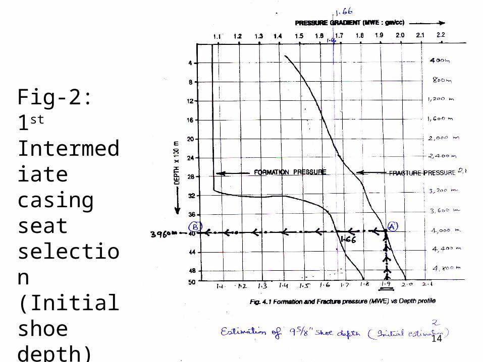
Fig-2:1st Intermediate casing seat selection (Initial shoe depth)
14

First casing (9-5/8”) seat selection
Function
Projected casing shoe depth
3,960 m
Formation pr at 3,960 m 1.66 gm/cc MWE
Swab pr + 0.04 gm/cc
Min MW at 3,960 m during drilling
= 1.70 gm/cc
Formation pr at 3,100 m 1.07 gm/cc MWE
Diff pr at 3,100 m when drilling at 3,960 m
{(1.70-1.07) * 3100}/10
Differential pr at 3,100 m 195.3 kg/cm2
Is it acceptable No
15
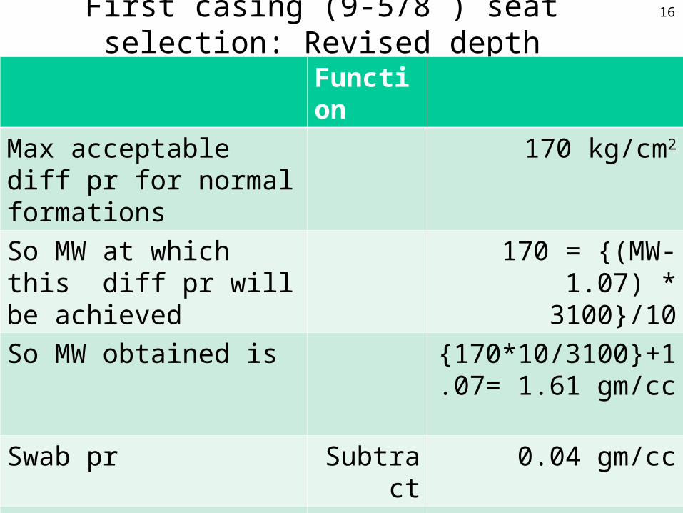
First casing (9-5/8”) seat selection: Revised depth
Function
Max acceptable diff pr for normal formations
170 kg/cm2
So MW at which this diff pr will be achieved
170 = {(MW-1.07) * 3100}/10
So MW obtained is {170*10/3100}+1.07= 1.61 gm/cc
Swab pr Subtract 0.04 gm/cc
So acceptable formation pr = 1.57 gm/cc MWE
So revised shoe depth 3,400 m
Fracture grad at 3,400 m 1.83 gm/cc MWE
16

Fig-3:1st Intermediate casing seat selection (Modified shoe depth)
17

Liner Seat Selection
MWE (gm/cc)
Fracture gradient at 3,400 m 1.83
Swab+ Surge+ SF Subtract 0.10
Formation pr 1.73
Projected liners setting depth at formation pr of 1.73 gm/cc
4,560 m
Is it final No
Check differential pr criterion
Check kick criterion
18

Fig-4:Liner seat selection
19

Liner seat selection: Diff Pr Criterion
Formation pr at 4,560 m 1.73 gm/cc
Swab pr Add 0.04 gm/cc
Min MW at 4,560 m Gives 1.77 gm/cc
Formation pr at last casing shoe (3,400 m)
1.57 gm/cc
So differential pr at 3,400 m {(1.77-1.57)*3400}/10 = 68 kg/cm2
Is it acceptable 170 kg/cm2 for normal 215 kg/cm2 for abnormal pr zones
Yes
20
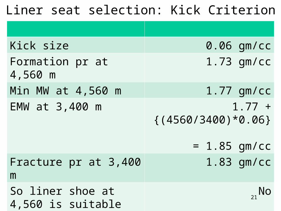
Liner seat selection: Kick Criterion
Kick size 0.06 gm/cc
Formation pr at 4,560 m 1.73 gm/cc
Min MW at 4,560 m 1.77 gm/cc
EMW at 3,400 m 1.77 + {(4560/3400)*0.06} = 1.85 gm/cc
Fracture pr at 3,400 m 1.83 gm/cc
So liner shoe at 4,560 is suitable
No
What to do Try again to set at some higher depth by trial
21

Revised Liner seat selection: Kick Criterion
What depth we try 4,200 m
Formation pr at 4,200 m 1.69 gm/cc
So MW at 4,200 m 1.73 gm/cc
So EMW at 3,400 m 1.73 + {(4200/3400)*0.06} = 1.80 gm/cc
Fracture gradient at 3,400 m 1.83 gm/cc
Is it satisfactory Yes
Lower liner here No
What to do Try again to set liner as deep as possible. Try again
22

Second casing (Liner) seat selection: Kick Criterion
What depth we try 4,320 m
Formation pr at 4,320 m 1.70 gm/cc
So MW at 4,320 m 1.74 gm/cc
So EMW at 3,400 m 1.74 + {(4320/3400)*0.06} = 1.83 gm/cc
Fracture gradient at 3,400 m 1.83 gm/cc
Is it satisfactory Too close
Lower liner here Set somewhere between 4,200 and 4,320 m
23

Third casing (13-3/8”) seat selection
MWE (gm/cc)
Max anticipated formation pr at 3,400 m
1.57
Swab + Surge + SF Add 0.10
Design fracture gradient Gives 1.67
Depth selected to lower 13-3/8” casing with this frac gradient of 1.67
2,200 m
What to do Find out 20” casing seat by
trial
24

Fig-5:2nd
Intermediate casing seat selection (Shoe depth)
25

Fourth casing (20”) seat selection
What depth we try 320 m
Formation pr at 2,200 m 1.07 gm/cc
So MW at 2,200 m 1.11 gm/cc
So EMW at 320 m with 0.06 gm/cc kick from 2,200 m
1.11 + {(2200/320)*0.06} = 1.52 gm/cc
Fracture gradient at 320 m 1.45 gm/cc
Is it satisfactory No way
Lower 20” casing here Keep shoe somewhere deeper
26

Fourth casing (20”) seat selection
What depth we try 400 m
Formation pr at 2,200 m 1.07 gm/cc
So MW at 2,200 m 1.11 gm/cc
So EMW at 400 m with 0.06 gm/cc kick from 2,200 m
1.11 + {(2200/400)*0.06} = 1.44 gm/cc
Fracture gradient at 400 m 1.46 gm/cc
Is it satisfactory YES
Lower 20” casing here YES
27

Summary
Csg size
Shoe (mtr)
20” 400
13-3/8”
2,200
9-5/8” 3,400
7” liner
4,320
28

Casing seat selection in weak Formations in Well
29
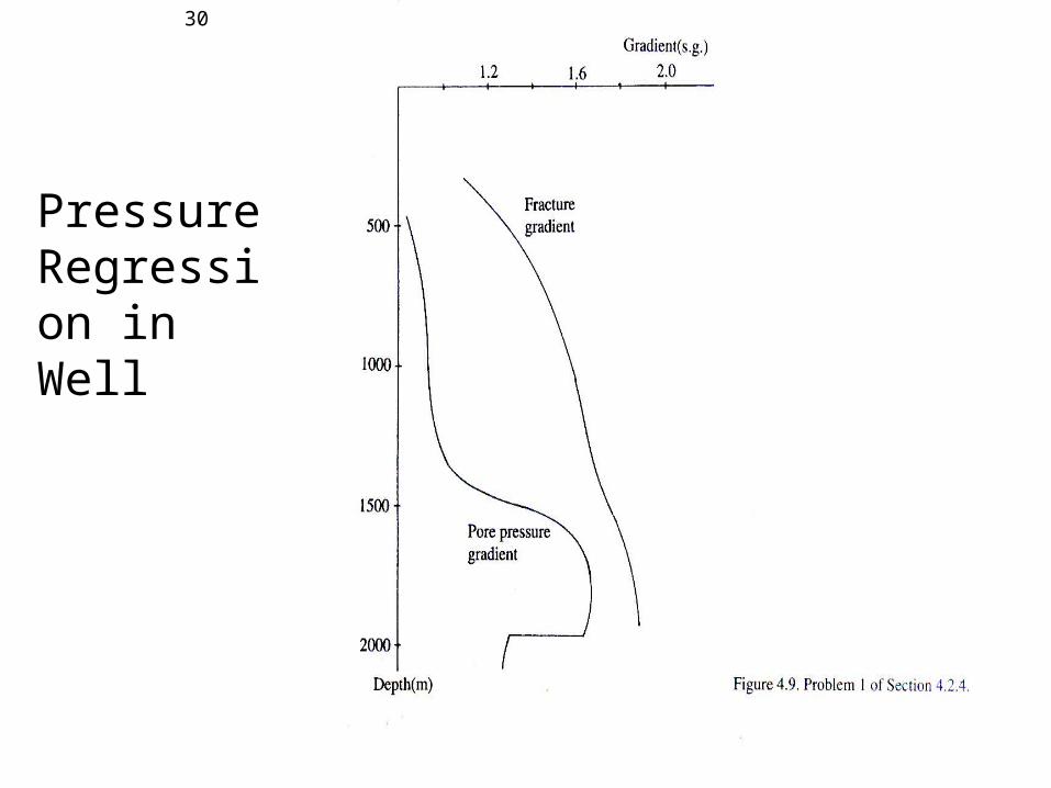
Pressure Regression in Well
30

Pore Pr & Fracture Pr Gradient of ONGC Well
31

Pore Pr & Fracture Pr Gradient of ONGC Well
• 13-3/8” shoe• Proposed at 300 m to seal fresh water sands
• 9-5/8” shoe:• Proposed at 1400/ 1450 m with objective of
covering upper pay sands with pore pr of 0.98 MWE
• 5-1/2” shoe:• Proposed at 2000 m covering lower pay
zones from 1800-2000 m and deeper zones below 2000 m
• Higher MW of 1.50 required to drill charged Cambay sand in 8-1/2” hole
32


