CSE 466 – Fall 2000 - Introduction - 1 Physical Layer API (same as Lab) enq(), deq(), scan() ...
34
CSE 466 – Fall 2000 - Introduction - 1 Physical Layer API (same as Lab) enq(), deq(), scan() Periodically if not currently master select non- empty outgoing queue send start condition (capture bus) On Interrupt if bus master and not end of frame send next byte, otherwise send stop condition if bus slave get byte and process header information, or place into appropriate incoming queue based on previous header information. Deal w/ flow control somehow (control frames for acknowledgement) Deal w/ Security dst port Timer Interrupt and External Interrupt Routines Function Calls
-
Upload
eric-adams -
Category
Documents
-
view
216 -
download
0
Transcript of CSE 466 – Fall 2000 - Introduction - 1 Physical Layer API (same as Lab) enq(), deq(), scan() ...

CSE 466 – Fall 2000 - Introduction - 1
Physical Layer API (same as Lab)
enq(), deq(), scan()
Periodically if not currently master select non-empty outgoing
queue send start condition (capture bus)
On Interrupt if bus master and not end of frame send next
byte, otherwise send stop condition if bus slave
get byte and process header information, or place into appropriate incoming queue based on previous header information.
Deal w/ flow control somehow (control frames for acknowledgement)
Deal w/ Security
dst
port
Timer Interrupt andExternal Interrupt Routines
Function Calls

CSE 466 – Fall 2000 - Introduction - 2
Debugging
A Complete Development Environment
Networking
FileI/O
DeviceI/O
Kernel
KernelTask SchedulingMemory ManagementResource ProtectionInterrupt HandlingTask-message PassingTask event management
File I/OFile Creation and DeletionFile I/ODirectory Structures and Navigation
Device I/ODevice Drivers
NetworkingProtocols and device driver support fordata communication. Task to Task message passing over a network.
DebuggingSimulationMonitor based DebuggingHardware Emulator

CSE 466 – Fall 2000 - Introduction - 3
Debugging
Simulation you’ve seen the limits of that approach.
In-System Debug (w/ a Monitor) Ability to download code and upload state
information (RAM, Regs) Breakpoints
replace instruction w/ SWI or JSR SWI waits for user commands On “continue” monitor executes the
trapped instruction and returns control to the app
Not good for final test unless monitor is part of shipped system
Requires system resources: interrupts, RAM, ROM.
HW Emulation A circuit board w/ a socket connector that
acts just like real processor. Allows debugging without a monitor
Monitor Program
Debugging HostserialinterfaceR/W code
and dataspace
SW basedsingle stepping
Single Stepping in the 8051ISR for External Interrupt 0JNB P3.2,$ ;Wait Here Till INT0 Goes HighJB P3.2,$ ;Now Wait Here Till it Goes LowRETI ;Go Back and Execute One Instruction
CSE 466 – Fall 2000 - Introduction - 4
Projects/Reports
Option 1: A final lab assignment … to be negotiated. Some improvement on music player (I think we can do 20K music at 11 MHz
anyway). Maybe Streaming from NT through one player to another player over I2C. No upload needed.
Chat A PCB for the Music Player w/I2C and Serial ports
Option 2: A report/presentation design approaches for some existing system
fuzzy logic controller design automotive apps and networking (ECU, Airbag, CAN) Embedded TCP (IP?/I2C?) Embedded web-servers Robot architectures Convergence devices Object technology for 8-bit microcontrollers
hw that we didn’t cover motors watchdog circuits DAC, ADC. audio codecs display…vga/lcd radios Memory devices and interfaces

CSE 466 – Fall 2000 - Introduction - 5
Safety
Examples
Terms and Concepts
Safety Architectures
Safe Design Process
Software Specific Stuff
Sources Hard Time by Bruce Powell Douglass, which references Safeware by
Nancy Leveson
CSE 466 – Fall 2000 - Introduction - 6
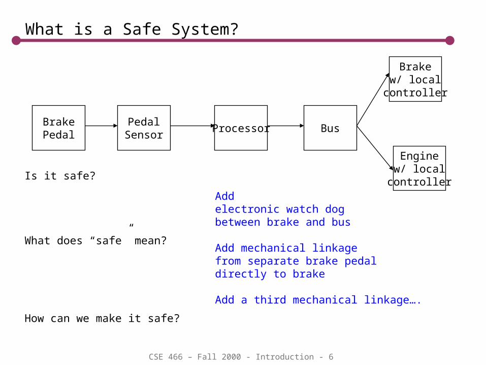
What is a Safe System?
BrakePedal
PedalSensor
Processor Bus
Brakew/ local
controller
Enginew/ local
controllerIs it safe?
What does “safe” mean?
How can we make it safe?
Addelectronic watch dogbetween brake and bus
Add mechanical linkagefrom separate brake pedaldirectly to brake
Add a third mechanical linkage….
CSE 466 – Fall 2000 - Introduction - 7
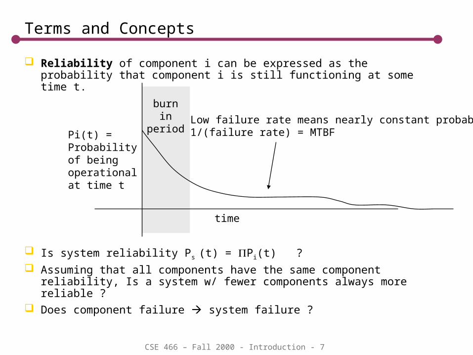
Reliability of component i can be expressed as the probability that component i is still functioning at some time t.
Is system reliability Ps (t) = Pi(t) ?
Assuming that all components have the same component reliability, Is a system w/ fewer components always more reliable ?
Does component failure system failure ?
burnin
period
Terms and Concepts
time
Pi(t) =Probabilityof beingoperationalat time t
Low failure rate means nearly constant probability1/(failure rate) = MTBF

CSE 466 – Fall 2000 - Introduction - 8
A Safety System
A system is safe if it’s deployment involves assuming an acceptable amount of risk…acceptable to whom?
Risk factors Probability of something bad happing Consequences of something bad happening (Severity)
Example Airplane Travel – high severity, low probability Electric shock from battery powered devices – hi probability, low severity
severity
probability
danger zone(we don’t all have the same risk tolerance!)
airplane autopilot
mp3 player
PC
safezone
CSE 466 – Fall 2000 - Introduction - 9
More Precise Terminology
Accident or Mishap: (unintended) Damage to property or harm to persons. Economic impact of failure to meet warranted performance is outside of the scope of safety.
Hazard: A state of the the system that will inevitably lead to an accident or mishap Release of Energy Release of Toxins Interference with life support functions Supplying misleading information to safety personnel or control systems.
This is the desktop PC nightmare scenario. Bad information Failure to alarm when hazardous conditions exist

CSE 466 – Fall 2000 - Introduction - 10
Faults
A fault is an “unsatisfactory system condition or state”. A fault is not necessarily a hazard. In fact, assessments of safety are based on the notion of fault tolerance.
Systemic faults Design Errors (includes process errors such as failure to test or failure to
apply a safety design process) Faults due to software bugs are systemic Security breech
Random Faults Random events that can cause permanent or temporary damage to the
system. Includes EMI and radiation, component failure, power supply problems, wear and tear.
CSE 466 – Fall 2000 - Introduction - 11
Component v. System
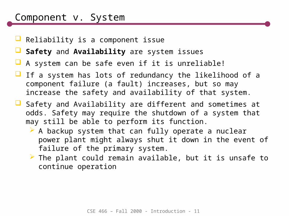
Reliability is a component issue
Safety and Availability are system issues
A system can be safe even if it is unreliable!
If a system has lots of redundancy the likelihood of a component failure (a fault) increases, but so may increase the safety and availability of that system.
Safety and Availability are different and sometimes at odds. Safety may require the shutdown of a system that may still be able to perform its function. A backup system that can fully operate a nuclear power plant might
always shut it down in the event of failure of the primary system. The plant could remain available, but it is unsafe to continue operation

CSE 466 – Fall 2000 - Introduction - 12
Single Fault Tolerance (for safety)
The existence of any single fault does not result in a hazard
Single fault tolerant systems are generally considered to be safe, but more stringent requirements may apply to high risk cases…airplanes, power plants, etc.
BackupH2 ValveControl
MainH2 ValveControl
watchdogprotocol
If the handshakefails, then either oneor both can shut off the gassupply. Is this a single faulttolerant system?
CSE 466 – Fall 2000 - Introduction - 13
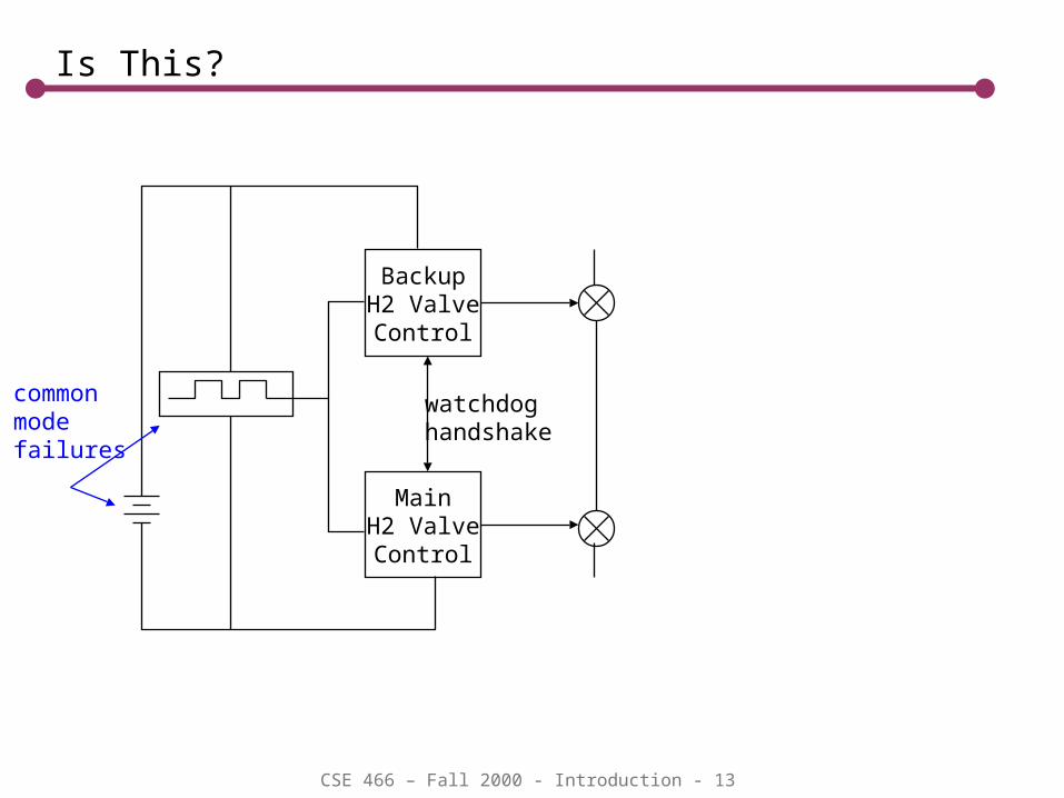
Is This?
BackupH2 ValveControl
MainH2 ValveControl
watchdoghandshake
commonmodefailures
CSE 466 – Fall 2000 - Introduction - 14
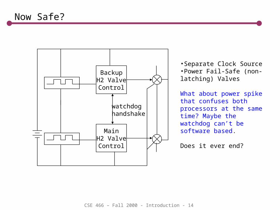
Now Safe?
BackupH2 ValveControl
MainH2 ValveControl
watchdoghandshake
•Separate Clock Source•Power Fail-Safe (non-latching) Valves
What about power spike that confuses both processors at the same time? Maybe the watchdog can’t be software based.
Does it ever end?

CSE 466 – Fall 2000 - Introduction - 15
Time is a Factor
The TUV Fault Assessment Flow Chart T0: Fault tolerance time of the first failure T1: Time after which a second fault is likely Captures time, and the notion of “latent faults”
T0 – tolerance time for first fault
T1 – Time after which a second fault is likely Based on MTBF data
Safety requires that Ttest<T0<T1
1st Fault
hazard afterT0?
SystemUnsafe
yes
no
2nd
FaultSystem
Safe
FaultDetectedbefore T1?
yes
no
yes
no
hazard?

CSE 466 – Fall 2000 - Introduction - 16
Latent Faults
Any fault this is not detectable by the system during operation has a probability of 1 – doesn’t count in single fault tolerance assessment
Detection might not mean diagnosis. If system can detect secondary affect of device failure before a hazard arises, then this could be considered safe
BackupH2 ValveControl
MainH2 ValveControl
watchdoghandshake
stuck valves couldbe latent if the controllers cannotcheck their state.
May as well assume thatthey are stuck!

CSE 466 – Fall 2000 - Introduction - 17
Fail-Safe Design (just an example)
On reset processor checks status. If bad, enter “safe mode” power off reduced/altered functionality alarm restart
Safe mode is application dependent
Processor Watchdogprotocol
protocolfailure
reset
status

CSE 466 – Fall 2000 - Introduction - 18
Safety Architectures
Self Checking (Single Channel Protected Design)
Redundancy
Diversity or Heterogeneity
BrakePedal
PedalSensor
ComputerComputer
Bus
Brake
EngineControl
watchdogprotocol
parity/crcPeriodic internalCRC/Checksumcomputation(code/data corruption)
CSE 466 – Fall 2000 - Introduction - 19
Single Channel Protection
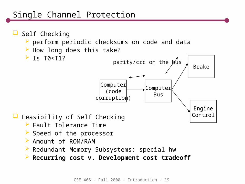
Self Checking perform periodic checksums on code and data How long does this take? Is T0<T1?
Feasibility of Self Checking Fault Tolerance Time Speed of the processor Amount of ROM/RAM Redundant Memory Subsystems: special hw Recurring cost v. Development cost tradeoff
Computer(code
corruption)
ComputerBus
Brake
EngineControl
parity/crc on the bus
CSE 466 – Fall 2000 - Introduction - 20
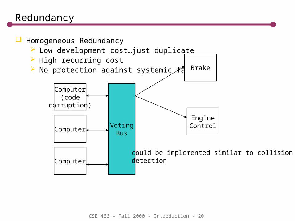
Redundancy
Homogeneous Redundancy Low development cost…just duplicate High recurring cost No protection against systemic faults
Computer(code
corruption)
Brake
EngineControl
Computer
ComputerVoting
Bus
could be implemented similar to collisiondetection
CSE 466 – Fall 2000 - Introduction - 21
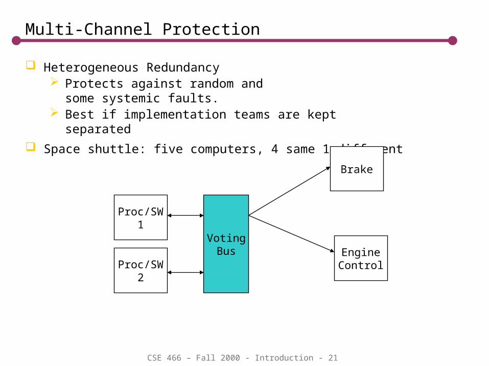
Multi-Channel Protection
Heterogeneous Redundancy Protects against random and
some systemic faults. Best if implementation teams are kept
separated
Space shuttle: five computers, 4 same 1 different
Proc/SW1
Brake
EngineControlProc/SW
2
VotingBus
CSE 466 – Fall 2000 - Introduction - 22
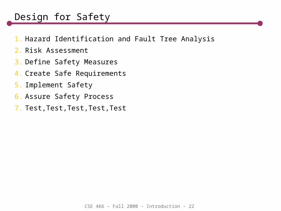
Design for Safety
1. Hazard Identification and Fault Tree Analysis
2. Risk Assessment
3. Define Safety Measures
4. Create Safe Requirements
5. Implement Safety
6. Assure Safety Process
7. Test,Test,Test,Test,Test

CSE 466 – Fall 2000 - Introduction - 23
1. Hazard Identification – Ventilator Example
Hazard Severity Tolerance Time
Fault Example
Likelihood Detection Time
Mechanism Exposure Time
Hypo-ventilation
Severe 5 min. Vent Fails Rare 30sec Indep. pressure sensor w/ alarm
40sec
Esophageal intubation
Medium 30sec C02 sensor alarm
40sec
User mis-attaches breathing hoses
never N/A Different mechanical fittings for intake and exhaust
N/A
Over-pressurization
Sever 0.05sec Release valve failure
Rare 0.01sec Secondary valve opens
0.01sec
Humanin Loop
CSE 466 – Fall 2000 - Introduction - 24
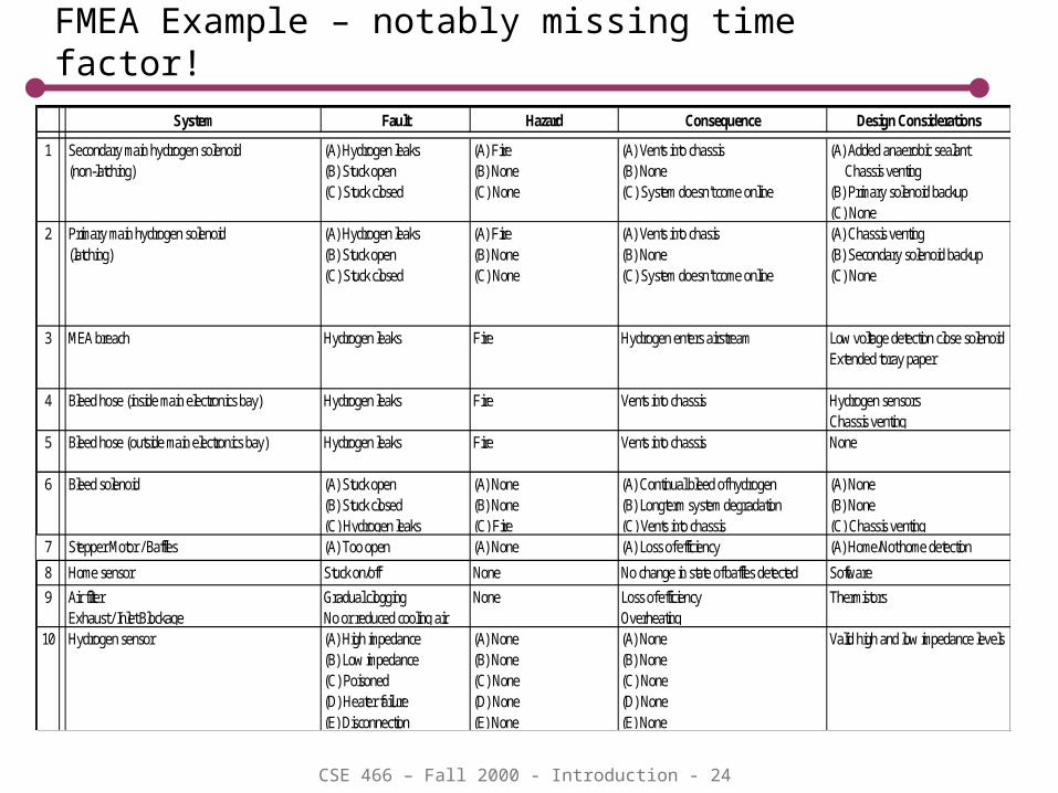
FMEA Example – notably missing time factor!System Fault Hazard Consequence Design Considerations
1 Secondary main hydrogen solenoid(non-latching)
(A) Hydrogen leaks(B) Stuck open(C) Stuck closed
(A) Fire(B) None(C) None
(A) Vents into chassis(B) None(C) System doesn't come online
(A) Added anaerobic sealant Chassis venting(B) Primary solenoid backup(C) None
2 Primary main hydrogen solenoid(latching)
(A) Hydrogen leaks(B) Stuck open(C) Stuck closed
(A) Fire(B) None(C) None
(A) Vents into chasis(B) None(C) System doesn't come online
(A) Chassis venting(B) Secondary solenoid backup(C) None
3 MEA breach Hydrogen leaks Fire Hydrogen enters airstream Low voltage detection close solenoidExtended toray paper
4 Bleed hose (inside main electronics bay) Hydrogen leaks Fire Vents into chassis Hydrogen sensorsChassis venting
5 Bleed hose (outside main electronics bay) Hydrogen leaks Fire Vents into chassis None
6 Bleed solenoid (A) Stuck open(B) Stuck closed(C) Hydrogen leaks
(A) None(B) None(C) Fire
(A) Continual bleed of hydrogen(B) Longterm system degradation(C) Vents into chassis
(A) None(B) None(C) Chassis venting
7 Stepper Motor / Baffles (A) Too open(B) Too closed
(A) None(B) None
(A) Loss of efficiency(B) Loss of efficiency
(A) Home/Not home detection Temp monitoring8 Home sensor Stuck on/off None No change in state of baffles detected Software
9 Air filterExhaust / Inlet Blockage
Gradual cloggingNo or reduced cooling air
None Loss of efficiencyOverheating
Thermistors
10 Hydrogen sensor (A) High impedance(B) Low impedance(C) Poisoned(D) Heater failure(E) Disconnection
(A) None(B) None(C) None(D) None(E) None
(A) None(B) None(C) None(D) None(E) None
Valid high and low impedance levels

CSE 466 – Fall 2000 - Introduction - 25
Fault Tree Analysis – working backwards
Pacemaker Example
single fault hazard
CSE 466 – Fall 2000 - Introduction - 26
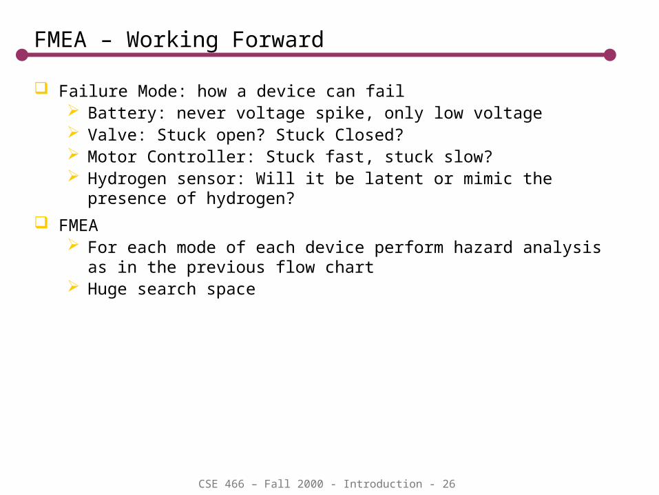
FMEA – Working Forward
Failure Mode: how a device can fail Battery: never voltage spike, only low voltage Valve: Stuck open? Stuck Closed? Motor Controller: Stuck fast, stuck slow? Hydrogen sensor: Will it be latent or mimic the presence of hydrogen?
FMEA For each mode of each device perform hazard analysis as in the
previous flow chart Huge search space
CSE 466 – Fall 2000 - Introduction - 27
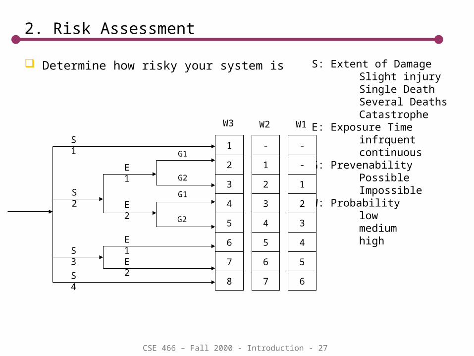
2. Risk Assessment
Determine how risky your system is S: Extent of DamageSlight injurySingle DeathSeveral DeathsCatastrophe
E: Exposure Timeinfrquentcontinuous
G: PrevenabilityPossibleImpossible
W: Probabilitylowmediumhigh
1
2
3
4
5
6
7
8
3
4
5
7
6
-
1
2
2
3
4
6
5
-
-
1
W3 W2 W1
S1
S3
S2
G2
G1
G2
G1
S4
E2
E1
E2
E1

CSE 466 – Fall 2000 - Introduction - 28
Example Risk Assessment
Device Hazard Extent of Damage
Exposure Time
Hazard Prevention
Probability
TUV Risk Level
Microwave Oven
Irradiation S2 E2 G2 W3 5
Pacemaker Pacing too slowly
Pacing too fast
S2 E2 G2 W3 5
Power station burner control
Explosion S3 E1 -- W3 6
Airliner Crash S4 E2 G2 W2 8

CSE 466 – Fall 2000 - Introduction - 29
3. Define the Safety Measures
Obviation: Make it physically impossible (mechanical hookups, etc).
Education: Educate users to prevent misuse or dangerous use.
Alarming: Inform the users/operators or higher level automatic monitors of hazardous conditions
Interlocks: Take steps to eliminate the hazard when conditions exist (shut off power, fuel supply, explode, etc.
Restrict Access. High voltage sources should be in compartments that require tools to access, w/ proper labels.
Labeling
Consider Tolerance time Supervision of the system: constant, occasional, unattended. Airport
People movers have to be design to a much higher level of safety than attended trains even if they both have fully automated control
CSE 466 – Fall 2000 - Introduction - 30
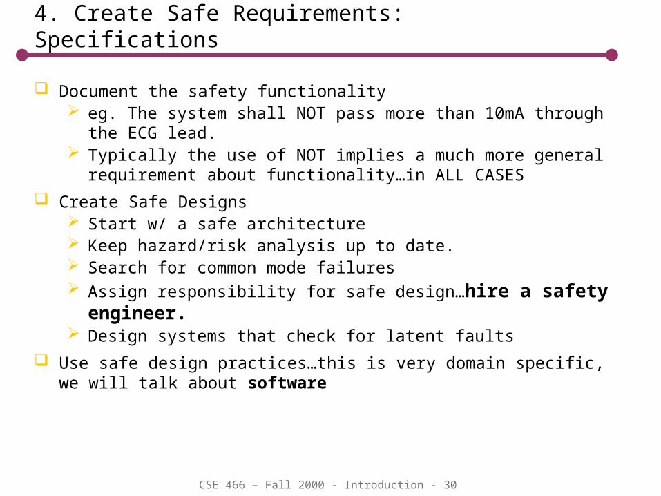
4. Create Safe Requirements: Specifications
Document the safety functionality eg. The system shall NOT pass more than 10mA through the ECG lead. Typically the use of NOT implies a much more general requirement
about functionality…in ALL CASES
Create Safe Designs Start w/ a safe architecture Keep hazard/risk analysis up to date. Search for common mode failures Assign responsibility for safe design…hire a safety engineer. Design systems that check for latent faults
Use safe design practices…this is very domain specific, we will talk about software
CSE 466 – Fall 2000 - Introduction - 31
5. Implement Safety – Safe Software
Language Features
Compile Time Checking
Run Time Checking
Exception Handling
Re-use
Objects
Operating Systems
Protocols
Testing
Regression Testing
Exception Testing (Fault Seeding)
CSE 466 – Fall 2000 - Introduction - 32
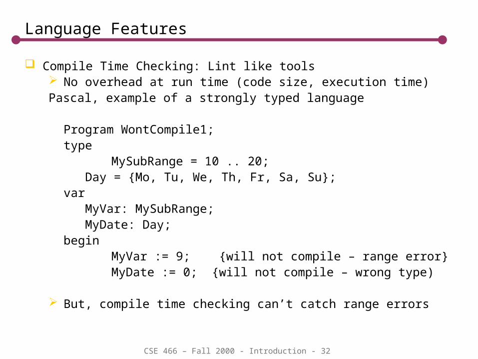
Language Features
Compile Time Checking: Lint like tools No overhead at run time (code size, execution time)Pascal, example of a strongly typed language
Program WontCompile1;type
MySubRange = 10 .. 20; Day = {Mo, Tu, We, Th, Fr, Sa, Su};var MyVar: MySubRange; MyDate: Day;begin
MyVar := 9; {will not compile – range error}MyDate := 0; {will not compile – wrong type)
But, compile time checking can’t catch range errors

CSE 466 – Fall 2000 - Introduction - 33
Error Checking in Software
CSE 466 – Fall 2000 - Introduction - 34
Testing