CSCI566 Computer Networking ©2011, MA Doman 1. Today – General Overview Course Overview ...
84
CSCI566 Computer Networking ©2011, MA Doman 1
-
Upload
berenice-pierce -
Category
Documents
-
view
218 -
download
1
Transcript of CSCI566 Computer Networking ©2011, MA Doman 1. Today – General Overview Course Overview ...

1
CSCI566 Computer Networking
©2011, MA Doman

2
Today – General Overview
Course Overview Introduce basic concepts and
vocabulary Networking overview Internet:
What is the internet Protocol layers
©2011 MA Doman

3
Course Objectives
Understand fundamental networking concepts
Understand important Internet protocols
Additionally Developing and executing a simulation and
analyzing its results. Apply the scientific method Analyze network system performance Gain a more solid understanding of networking
concepts
©2011 MA Doman

4
Course Methodology
Lecture Concept overview Algorithm/protocol examples
Homework exercises To help understanding of the material
Lab exercises Simulation Programming
Presentation/paper
©2011 MA Doman

5
Assessment Materials
Exams
Lab exercises Simulation Programming
Homework participation
©2011 MA Doman

6
Grading Policy
Undergraduate Students
30% Labs 20% Exam 120% Exam 215% Exam 310% Cumulative final exam5% Homework Participation
©2011 MA Doman

7
Grading Policy
Graduate Students
30% Labs and Presentation/Paper15% Exam 115% Exam 215% Exam 310% Cumulative final exam
15 % Paper and presentation on Network Management
©2011 MA Doman

8
Final Exam
You will put together what you learned about Internet protocols:
Suppose you walk into a room, connect to the Ethernet and start to download a web page. What are all the protocol steps that take place starting from powering on your PC to getting the web page?
©2011 MA Doman

Introduction
Chapter 1Introduction
Computer Networking: A
Top Down Approach
6th edition Jim Kurose, Keith
RossAddison-Wesley
March 2012
All material copyright 1996-2012
J.F Kurose and K.W. Ross, All Rights Reserved
Additions and modifications by L.Denoia and M Doman
Introduction
Chapter 1: roadmap1. Structure of networks2. what is the Internet?3. network edge
end systems, access networks, links4. network core
packet switching, circuit switching, network structure
5. delay, loss, throughput in networks6. networks under attack: security
1-10

11
What is a Network?
Basically, the collection of elements needed to enable information exchange between people, systems, or people and systems Hardware
• End points, routers, switches.. Software
• Protocols, end applications .. Transmission media
• Wires, air … Services
• Reliability• Completeness of messages
©2011 MA Doman
13
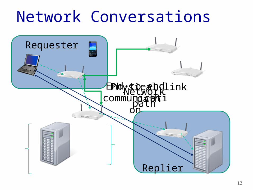
Network Conversations
Requester
Replier
End-to-end communication
Network pathPhysical link path

14
Fundamental Definitions
Protocol rules for conversation and
behavior Architecture
framework, blueprint functional perspective
Interface service
offerings/expectations
©2005, L.A. DeNoia

Introduction 1-15
What’s a protocol?
human protocols: “what’s the time?” “I have a question” introductions
… specific msgs sent… specific actions
taken when msgs received, or other events
network protocols: machines rather
than humans all communication
activity in Internet governed by protocols
protocols define format, order of msgs sent and
received among network entities,
and actions taken on msg transmission,
receipt

Introduction
a human protocol and a computer network protocol:
Q: other human protocols?
Hi
HiGot the
time?
2:00
TCP connection
response
time
TCP connection
request
What’s a protocol?
1-16
<file>
<send file >

17
A Layered Architecture… also known as a Stack of Protocols
LAYERS: Each system is viewed logically as composed of an ordered set of subsystems.
INTERFACE: Adjacent subsystems in the vertical hierarchy (the layers) communicate through a common boundary.
ENTITIES: Functional module of each layer. Entities in the same layer but installed on different systems are called “peer” entities.
PROTOCOLS: Peer entities communicate through peer “protocols” at the appropriate (containing) layer.
18
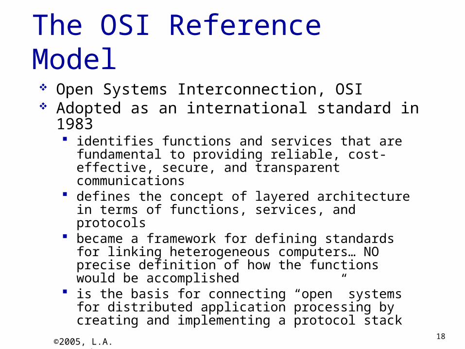
The OSI Reference Model Open Systems Interconnection, OSI Adopted as an international standard in 1983
identifies functions and services that are fundamental to providing reliable, cost-effective, secure, and transparent communications
defines the concept of layered architecture in terms of functions, services, and protocols
became a framework for defining standards for linking heterogeneous computers… NO precise definition of how the functions would be accomplished
is the basis for connecting “open” systems for distributed application processing by creating and implementing a protocol stack
©2005, L.A. DeNoia

19
OSI Layers
OSI ReferenceApplication FTAM, X.400, etc.
Presentation ISO 8823
Session ISO 8327
Transport ISO 8073
Network ISO 8473
Data Link ISO 8802.x LLC/MAC
Physical physical
©2005, L.A. DeNoia

Introduction 1-20
Internet protocol stack application: supporting
network applications FTP, SMTP, HTTP
transport: process-process data transfer TCP, UDP
network: routing of datagrams from source to destination IP, routing protocols
link: data transfer between neighboring network elements Ethernet, 802.111 (WiFi), PPP
physical: bits “on the wire”
Application
Transport
Network
Link
Physical

21
Internet (TCP/IP) and OSI Layers
Internet Suite OSI Reference
Telnet, FTP, SMTP, HTTP, etc.
Application
Application FTAM, X.400, etc.
Presentation ISO 8823
Session ISO 8327
TCP, UDP Host-to-host Transport ISO 8073
Network IP, ICMP, etc. Network ISO 8473
Link 802.x MAC Data LinkISO 8802.x LLC/MAC
Physical 802.x phys Physical physical
©2005, L.A. DeNoia

22
Up and Down the Layers
©2005, L.A. DeNoia
PhysLink
Network
TCPserver
PhysLink
Network
TCPbrowser
PhyLink
Network
PhysLink
Open System A
Relay Node
Open System B
HTTP msgTCP segment
pkt
frm
bits
router

23
TCP/IP View of Encapsulation
©2005, L.A. DeNoia
User Data
TCP segment
Network segment
Link layer segment
MAC frame
TCP hdr
IP hdr
Linkhdr
MAC trlr
MAC hdr

24
TCP/IP Message Flow
©2005, L.A. DeNoia
Data Link Layer Data Link Layer
Network Layer Network Layer
Physical Layer Physical Layer
Service Access
Point
Ethernet frames
bits
Interface
Transport Layer Transport Layer
Application Layer Application Layer
IP packets
TCP segments
HTTP messages

Introduction
Chapter 1: roadmap1. Structure of networks2. What is the Internet?3. Network edge
end systems, access networks, links4. Network core
packet switching, circuit switching, network structure
5. Delay, loss, throughput in networks6. Networks under attack: security
1-25

26
What about the Internet?
©2005, L.A. DeNoia
ISP network
The “big I” Internet
ISP network
Regional network
Regional network
ISP network
Web server
Web client

Introduction
1-27
Internet: “network of networks” Interconnected ISPs
protocols control sending, receiving of msgs e.g., TCP, IP, HTTP, Skype,
802.11 Internet standards
RFC: Request for comments IETF: Internet Engineering
Task Force
What’s the Internet ?
mobile network
global ISP
regional ISP
home
network
institutional
network

Introduction
What’s the Internet: “nuts and bolts” view
millions of connected computing devices:
hosts = end systems
running network apps
communication links
fiber, copper, radio,
satellite transmission
rate: bandwidth
Packet switches: forward packets (chunks of data)
routers and switches
wired
links
wireless
links
router
mobile network
global ISP
regional ISP
home
network
institutional
network
smartphone
PC
server
wireless
laptop
1-28

Introduction
Internet history
1961: Kleinrock - queueing theory shows effectiveness of packet-switching
1964: Baran - packet-switching in military nets
1967: ARPAnet conceived by Advanced Research Projects Agency
1969: first ARPAnet node operational
1972: ARPAnet public demo first e-mail program ARPAnet has 15 nodes
1961-1972: Early packet-switching principles
1-29

Introduction
1970: ALOHAnet satellite network in Hawaii
1974: Cerf and Kahn - architecture for interconnecting networks
1976: Ethernet at Xerox PARC
late70’s: proprietary architectures: DECnet, SNA, XNA
late 70’s: switching fixed length packets (ATM precursor)
1979: ARPAnet has 200 nodes
Cerf and Kahn’s internetworking principles: minimalism, autonomy
- no internal changes required to interconnect networks
best effort service model
stateless routers decentralized control
define today’s Internet architecture
1972-1980: Internetworking, new and proprietary nets
Internet history
1-30

Introduction
1983: deployment of TCP/IP
1982: smtp e-mail protocol defined
1983: DNS defined for name-to-IP-address translation
1985: ftp protocol defined
1988: TCP congestion control
new national networks: Csnet, BITnet, NSFnet, Minitel
100,000 hosts connected to confederation of networks
1980-1990: new protocols, a proliferation of networks
Internet history
1-31

Introduction
early 1990’s: ARPAnet decommissioned
1991: NSF lifts restrictions on commercial use of NSFnet (decommissioned, 1995)
early 1990s: Web hypertext [Bush 1945,
Nelson 1960’s] HTML, HTTP: Berners-
Lee 1994: Mosaic, later
Netscape late 1990’s:
commercialization of the Web
late 1990’s – 2000’s: more killer apps:
instant messaging, P2P file sharing
network security to forefront
est. 50 million host, 100 million+ users
backbone links running at Gbps
1990, 2000’s: commercialization, the Web, new apps
Internet history
1-32

Introduction
2005-present ~750 million hosts
Smartphones and tablets Aggressive deployment of broadband access Increasing ubiquity of high-speed wireless
access Emergence of online social networks:
Facebook: soon one billion users Service providers (Google, Microsoft) create
their own networks Bypass Internet, providing
“instantaneous” access to search, emai, etc.
E-commerce, universities, enterprises running their services in “cloud” (eg, Amazon EC2)
Internet history
1-33

34
Internet Engineering Task Force (IETF) The IETF's mission is "to make the
Internet work better," but it is the Internet Engineering Task Force, so this means: make the Internet work better from an engineering point of view.
Manages the Request for Comment (RFC) publication process
Request for Comment (RFC) Format to request changes or updates to
the protocols and architecture for internet communications implementations.
http://www.ietf.org/

35
Internet Society
Mission:To promote the open development, evolution, and use of the Internet for the benefit of all people throughout the world.
Focused more on policy
http://www.internetsociety.org/

Introduction
Chapter 1: roadmap1. Structure of networks2. What is the Internet?3. Network edge
end systems, access networks, links4. Network core
packet switching, circuit switching, network structure
5. Delay, loss, throughput in networks6. Networks under attack: security
1-36

Introduction
A closer look at network structure:
network edge: hosts: clients and
servers servers often in data
centers
access networks, physical media: wired, wireless communication
links network core: interconnected
routersnetwork of
networks
mobile network
global ISP
regional ISP
home
network
institutional
network
1-37

Introduction
Access networks and physical media
Q: How to connect end systems to edge router?
residential access nets institutional access
networks (school, company)
mobile access networks
keep in mind: bandwidth (bits per
second) of access network?
shared or dedicated?1-38

Introduction
Access net: digital subscriber line (DSL)
central office
ISP
telephone
network
DSLAM
voice, data transmitted
at different frequencies over
dedicated line to central office use existing telephone line to central office
DSLAM data over DSL phone line goes to Internet voice over DSL phone line goes to telephone
net < 2.5 Mbps upstream transmission rate
(typically < 1 Mbps) < 24 Mbps downstream transmission rate
( <10Mbps)
DSL
modemsplitter
DSL access
multiplexer
1-39

Introduction
Access net: cable network
cable
modem
splitter
…cable headend
Channels
V
I
D
E
O
V
I
D
E
O
V
I
D
E
O
V
I
D
E
O
V
I
D
E
O
V
I
D
E
O
D
A
T
A
C
O
N
T
R
O
L
1 2 3 4 5 6 7 8 9
frequency division multiplexing: different channels transmitted
in different frequency bands1-40
D
A
T
A

Introduction
data, TV transmitted at different
frequencies over shared cable
distribution network
cable
modem
splitter
…cable headend
CMTS
ISP
cable modem
termination system
HFC: hybrid fiber coax asymmetric: up to 30Mbps downstream
transmission rate, 2 Mbps upstream transmission rate
network of cable, fiber attaches homes to ISP router homes share access network to cable
headend unlike DSL, which has dedicated access to
central office
Access net: cable network
1-41

Introduction
Access net: home network
to/from headend or central office
cable or DSL modem
router, firewall, NAT
wired Ethernet (100 Mbps)
wireless access
point (54 Mbps)
wireless
devices
often combined
in single box
1-42

Introduction
Enterprise access networks (Ethernet)
typically used in companies, universities, etc 10 Mbps, 100Mbps, 1Gbps, 10Gbps transmission
rates today, end systems typically connect into
Ethernet switch
Ethernet
switch
institutional mail,
web servers
institutional router
institutional link to
ISP (Internet)
1-43
Introduction
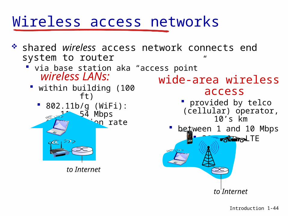
Wireless access networks
shared wireless access network connects end system to router via base station aka “access point”
wireless LANs: within building (100 ft) 802.11b/g (WiFi): 11, 54
Mbps transmission rate
wide-area wireless access
provided by telco (cellular) operator, 10’s km
between 1 and 10 Mbps 3G, 4G: LTE
to Internet
to Internet
1-44

Host: sends packets of data
host sending function: takes application
message breaks into smaller
chunks, known as packets, of length L bits
transmits packet into access network at transmission rate R link transmission
rate, aka link capacity, aka link bandwidth
R: link transmission ratehost
12
two packets,
L bits each
Packet transmission delaytime needed to
transmit L-bit
packet into link
L (bits)
R (bits/sec)= =
1-45

Introduction
Physical media
bit: propagates betweentransmitter/receiver pairs
physical link: what lies between transmitter & receiver
guided media: signals propagate in
solid media: copper, fiber, coax
unguided media: signals propagate
freely, e.g., radio
twisted pair (TP) two insulated copper
wires Category 5: 100
Mbps, 1 Gpbs Ethernet
Category 6: 10Gbps
1-46

Introduction
Physical media: coax, fiber
coaxial cable: two concentric copper
conductors bidirectional broadband:
multiple channels on cable
HFC
fiber optic cable: glass fiber carrying
light pulses, each pulse a bit
high-speed operation:
high-speed point-to-point transmission (e.g., 10’s-100’s Gpbs transmission
rate) low error rate:
repeaters spaced far apart
immune to electromagnetic noise
1-47

Introduction
Physical media: radio
signal carried in electromagnetic spectrum
no physical “wire” bidirectional propagation
environment effects: reflection obstruction by
objects interference
radio link types: terrestrial microwave
e.g. up to 45 Mbps channels
LAN (e.g., WiFi) 11Mbps, 54 Mbps
wide-area (e.g., cellular)
3G cellular: ~ few Mbps satellite
Kbps to 45Mbps channel (or multiple smaller
channels) 270 msec end-end delay
geosynchronous versus low altitude 1-48

Introduction
Chapter 1: roadmap1. Structure of networks2. What is the Internet?3. Network edge
end systems, access networks, links4. Network core
packet switching, circuit switching, network structure
5. Delay, loss, throughput in networks6. Networks under attack: security
1-49

Introduction
mesh of interconnected routers
packet-switching: hosts break application-layer messages into packets forward packets from
one router to the next, across links on path from source to destination
each packet transmitted at full link capacity
The network core
1-50

Host: sends packets of data
host sending function: takes application
message breaks into smaller
chunks, known as packets, of length L bits
transmits packet into access network at transmission rate R link transmission
rate, aka link capacity, aka link bandwidth
R: link transmission ratehost
12
two packets,
L bits each
Packet transmission delaytime needed to
transmit L-bit
packet into link
L (bits)
R (bits/sec)= =
1-51

Introduction
Packet-switching: store-and-forward
takes L/R seconds to transmit (push out) L-bit packet into link at R bps
store and forward: entire packet must arrive at router before it can be transmitted on next link
one-hop numerical example:
L = 7.5 Mbits R = 1.5 Mbps one-hop
transmission delay = 5 sec
more on delay shortly …1-52
sourceR bps destination
123
L bitsper packet
R bps
end-end delay = 2L/R (assuming zero
propagation delay)

Introduction
Packet Switching: queueing delay, loss
A
B
CR = 100 Mb/s
R = 1.5 Mb/s D
Equeue of packets
waiting for output link
1-53
queuing and loss: If arrival rate (in bits) to link exceeds transmission rate of link for a period of
time: packets will queue, wait to be
transmitted on link packets can be dropped (lost) if
memory (buffer) fills up

Network Layer 4-54
Two key network-core functions
forwarding: move packets from router’s input to appropriate router output
routing: determines source-destination
route taken by packets routing algorithmsrouting algorithm
local forwarding tableheader value output link
0100
0101
0111
1001
3
2
2
1
1
23
0111
dest address in arriving
packet’s header

Introduction
Alternative core: circuit switchingend-end resources
allocated to, reserved for “call” between source & dest:
In diagram, each link has four circuits. call gets 2nd circuit in
top link and 1st circuit in right link.
dedicated resources: no sharing circuit-like
(guaranteed) performance
circuit segment idle if not used by call (no sharing)
Commonly used in traditional telephone networks
1-55

Introduction
Circuit switching: FDM versus TDM
FDM
frequency
timeTDM
frequency
time
4 usersExample:
1-56

Introduction
Packet switching versus circuit switching
example: 1 Mb/s link each user:
• 100 kb/s when “active”• active 10% of time
circuit-switching: 10 users
packet switching: with 35 users,
probability > 10 active at same time is less than .0004 *
packet switching allows more users to use network!
N
users1 Mbps link
Q: how did we get value 0.0004?
Q: what happens if > 35 users ?
…..
1-57* Check out the online interactive exercises for more examples
Introduction
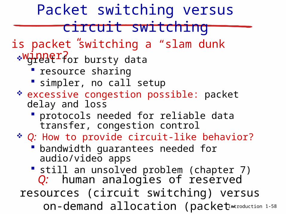
great for bursty data resource sharing simpler, no call setup
excessive congestion possible: packet delay and loss protocols needed for reliable data transfer,
congestion control Q: How to provide circuit-like behavior?
bandwidth guarantees needed for audio/video apps
still an unsolved problem (chapter 7)
is packet switching a “slam dunk winner?”
Q: human analogies of reserved resources (circuit switching) versus on-demand
allocation (packet-switching)?
Packet switching versus circuit switching
1-58

Internet structure: network of networks
End systems connect to Internet via access ISPs (Internet Service Providers) Residential, company and university
ISPs Access ISPs in turn must be
interconnected. So that any two hosts can send packets
to each other Resulting network of networks is very
complexEvolution was driven by economics and
national policies Let’s take a stepwise approach to describe
current Internet structure

Internet structure: network of networks
Question: given millions of access ISPs, how to connect them together?
access
net
access
net
access
net
access
net
access
net
access
net
access
net
access
net
access
net
access
net
access
net
access
net
access
net
access
netaccess
net
access
net
…
………
…
…

Internet structure: network of networks
Option: connect each access ISP to every other access ISP?
access
net
access
net
access
net
access
net
access
net
access
net
access
net
access
net
access
net
access
net
access
net
access
net
access
net
access
netaccess
net
access
net
…
………
…
…
…
…
………
connecting each access ISP to each other directly
doesn’t scale: O(N2) connections.

Internet structure: network of networks
access
net
access
net
access
net
access
net
access
net
access
net
access
net
access
net
access
net
access
net
access
net
access
net
access
net
access
netaccess
net
access
net
…
………
…
…
Option: connect each access ISP to a global transit ISP? Customer and provider ISPs have
economic agreement.
globalISP

Internet structure: network of networks
access
net
access
net
access
net
access
net
access
net
access
net
access
net
access
net
access
net
access
net
access
net
access
net
access
net
access
netaccess
net
access
net
…
………
…
…
But if one global ISP is viable business, there will be competitors ….
ISP B
ISP A
ISP C

Internet structure: network of networks
access
net
access
net
access
net
access
net
access
net
access
net
access
net
access
net
access
net
access
net
access
net
access
net
access
net
access
netaccess
net
access
net
…
………
…
…
But if one global ISP is viable business, there will be competitors …. which must be
interconnected
ISP B
ISP A
ISP C
IXP
IXP
peering link
Internet exchange point

Internet structure: network of networks
access
net
access
net
access
net
access
net
access
net
access
net
access
net
access
net
access
net
access
net
access
net
access
net
access
net
access
netaccess
net
access
net
…
………
…
…
… and regional networks may arise to connect access nets to ISPS
ISP B
ISP A
ISP C
IXP
IXP
regional net

Internet structure: network of networks
access
net
access
net
access
net
access
net
access
net
access
net
access
net
access
net
access
net
access
net
access
net
access
net
access
net
access
netaccess
net
access
net
…
………
…
…
… and content provider networks (e.g., Google, Microsoft, Akamai ) may run their
own network, to bring services, content close to end users
ISP B
ISP A
ISP B
IXP
IXP
regional net
Content provider network

Introduction
Internet structure: network of networks
at center: small # of well-connected large networks “tier-1” commercial ISPs (e.g., Level 3, Sprint, AT&T, NTT),
national & international coverage content provider network (e.g, Google): private network
that connects it data centers to Internet, often bypassing tier-1, regional ISPs
1-67
access
ISP
access
ISP
access
ISP
access
ISP
access
ISP
access
ISP
access
ISP
access
ISP
Regional ISP Regional ISP
IXP IXP
Tier 1 ISP Tier 1 ISP Google
IXP

Introduction
Chapter 1: roadmap1. Structure of networks2. What is the Internet?3. Network edge
end systems, access networks, links4. Network core
packet switching, circuit switching, network structure
5. Delay, loss, throughput in networks6. Networks under attack: security
1-69

Introduction
How do loss and delay occur?
packets queue in router buffers packet arrival rate to link (temporarily) exceeds
output link capacity packets queue, wait for turn
A
B
packet being transmitted (delay)
packets queueing (delay)
free (available) buffers: arriving packets
dropped (loss) if no free buffers
1-70

Introduction
Four sources of packet delay
dproc: nodal processing
check bit errors determine output
link typically < msec
A
B
propagation
transmission
nodal
processingqueueing
dqueue: queueing delay
time waiting at output link for transmission
depends on congestion level
of router
dnodal = dproc + dqueue + dtrans + dprop
1-71

Introduction
dtrans: transmission delay:
L: packet length (bits) R: link bandwidth (bps)
dtrans = L/R
dprop: propagation delay:
d: length of physical link s: propagation speed in
medium (~2x10⁸ m/sec) dprop = d/s
dtrans and dprop
very different
Four sources of packet delay
propagation
nodal
processingqueueing
dnodal = dproc + dqueue + dtrans + dprop
1-72
A
B
transmission
* Check out the Java applet for an interactive animation on trans vs. prop delay

Introduction
“Real” Internet delays and routes
what do “real” Internet delay & loss look like?
traceroute program: provides delay measurement from source to router along end-end Internet path towards destination. For all i: sends three packets that will reach router i
on path towards destination router i will return packets to sender sender times interval between transmission
and reply.3 probes
3 probes
3 probes
1-76

Introduction
“Real” Internet delays, routes
traceroute: winthrop.edu to www.eurecom.fr
Windows:
tracert: winthrop.edu to www.eurecom.fr
1-77

Introduction
Packet loss queue (aka buffer) preceding link in buffer
has finite capacity packet arriving to full queue dropped (aka
lost) lost packet may be retransmitted by
previous node, by source end system, or not at all
A
B
packet being transmitted
packet arriving to
full buffer is lost
buffer
(waiting area)
1-78* Check out the Java applet for an interactive animation on queuing and loss

Introduction
Throughput throughput: rate (bits/time unit) at
which bits transferred between sender/receiver instantaneous: rate at given point in time average: rate over longer period of time
server, with
file of F bits
to send to client
link capacity
Rs bits/sec
link capacity
Rc bits/sec
server sends bits
(fluid) into pipe
pipe that can carry
fluid at rate
Rs bits/sec)
pipe that can carry
fluid at rate
Rc bits/sec)1-79

Introduction
Throughput (more)
Rs < Rc What is average end-end throughput?
Rs bits/sec Rc bits/sec
Rs > Rc What is average end-end throughput?
link on end-end path that constrains end-end throughput
bottleneck link
Rs bits/sec Rc bits/sec
1-80

Introduction
Throughput: Internet scenario
10 connections (fairly) share backbone bottleneck link R bits/sec
Rs
Rs
Rs
Rc
Rc
Rc
R
per-connection end-end throughput: min(Rc,Rs,R/10)
in practice: Rc or Rs is often bottleneck
1-81

Introduction
Chapter 1: roadmap1. Structure of networks2. What is the Internet?3. Network edge
end systems, access networks, links4. Network core
packet switching, circuit switching, network structure
5. Delay, loss, throughput in networks6. Networks under attack: security
1-82

Introduction
Network security field of network security:
how bad guys can attack computer networks
how we can defend networks against attacks
how to design architectures that are immune to attacks
Internet not originally designed with (much) security in mind original vision: “a group of mutually trusting
users attached to a transparent network” Internet protocol designers playing “catch-
up” security considerations in all layers!
1-83

Introduction
Bad guys: put malware into hosts via Internet
malware can get in host from: virus: self-replicating infection by
receiving/executing object (e.g., e-mail attachment)
worm: self-replicating infection by passively receiving object that gets itself executed
spyware malware can record keystrokes, web sites visited, upload info to collection site
infected host can be enrolled in botnet, used for spam. DDoS attacks
1-84

Introduction
target
Denial of Service (DoS): attackers make resources (server, bandwidth) unavailable to legitimate traffic by overwhelming resource with bogus traffic
1. select target
2. break into hosts around the network (see botnet)
3. send packets to target from compromised hosts
Bad guys: attack server, network infrastructure
1-85

Introduction
Bad guys can sniff packets
packet “sniffing”: broadcast media (shared ethernet, wireless) promiscuous network interface reads/records
all packets (e.g., including passwords!) passing by
A
B
C
src:B dest:A payload
wireshark software is a (free) packet-sniffer
1-86

Introduction
Bad guys can use fake addressesIP spoofing: send packet with false source
addressA
B
C
src:B dest:A payload
1-87
… lots more on security (throughout, Chapter 8)

Introduction
Introduction: summary
covered a “ton” of material!
what’s a protocol? layering, service models Internet overview
History network edge, core,
access network packet-switching
versus circuit-switching
Internet structure performance: loss,
delay, throughput security
you now have: context, overview,
“feel” of networking more depth, detail
to follow!
1-88
89
Thank You!
Be sure to start the first lab: Introduction to the OpNet Simulator