CSC 382: Computer SecuritySlide #1 CSC 382: Computer Security Malware.
Upload
jubrilak5815Category
view
213download
0description
Kaduna State University
Department of Mathematical Sciences
CSC 305: Computer Architecture and Organizationby
Muhammad Aminu Ahmad© 2012

Overview
• Introduction• Structure• von Neumann Machine• Control Unit• Memory• Machine Instruction• Instruction Execution• CPU Bus Structure• Interrupts• Input/Output• Pipelining• Buses• RISC and CISC

Introduction• The study of Computer Architecture is the study of the organization and
interconnection of components of computer systems. Computer architects construct computers from basic buildings blocks such as memories, arithmetic units and buses. From those building blocks the Computer Architecture can construct any number of different types of computers.
• Computer Architecture refers to those attributes of a system that have a direct impact on the logical execution of a program. Examples:– the instruction set– the number of bits used to represent various data types– I/O mechanisms– memory addressing techniques
• Computer Organization refers to the operational units and their interconnections that realize the architectural specifications. Examples are things that are transparent to the programmer:– control signals– interfaces between computer and peripherals– the memory technology being used
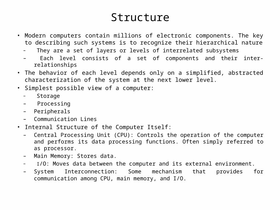
Structure
• Modern computers contain millions of electronic components. The key to describing such systems is to recognize their hierarchical nature– They are a set of layers or levels of interrelated subsystems– Each level consists of a set of components and their inter-relationships
• The behavior of each level depends only on a simplified, abstracted characterization of the system at the next lower level.
• Simplest possible view of a computer:– Storage– Processing– Peripherals– Communication Lines
• Internal Structure of the Computer Itself:– Central Processing Unit (CPU): Controls the operation of the computer and performs
its data processing functions. Often simply referred to as processor.– Main Memory: Stores data.– I/O: Moves data between the computer and its external environment.– System Interconnection: Some mechanism that provides for communication among
CPU, main memory, and I/O.


Structure (Cont.)
• Main Structural components of the CPU:– Control Unit: Controls the operation of the CPU and hence the computer.– Arithmetic and Logic Unit (ALU): Performs the computer's data processing functions.– Registers: Provides storage internal to the CPU.– CPU Interconnection: Some mechanism that provides for communication among the
control unit, ALU, and registers.
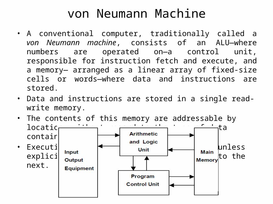
von Neumann Machine• A conventional computer, traditionally called a von Neumann machine,
consists of an ALU—where numbers are operated on—a control unit, responsible for instruction fetch and execute, and a memory— arranged as a linear array of fixed-size cells or words—where data and instructions are stored.
• Data and instructions are stored in a single read-write memory.• The contents of this memory are addressable by location, without regard
to the type of data contained there.• Execution occurs in a sequential fashion (unless explicitly modified) from
one instruction to the next.

Control Unit
Control Unit
• The main feature of the computer, the feature that makes it so different from other machines, is the internal control. The computer is controlled by a program, which specifies the operations to be performed.
• The program is located in memory, outside the processor, and the processor executes the program by reading (fetching) it from memory, instruction by instruction, and executing each instruction. This task is performed mainly by the control unit (CU), which uses the ALU and the registers as tools.
• The ALU is that part of the processor where operations are performed on numbers.
• The registers, as mentioned earlier, are fast, temporary storage.• The control unit is the main part of the processor. It performs its task by
repeatedly cycling through the following steps:– Read (fetch) the next instruction from memory.– Examine the instruction to determine what it is and to find any possible errors.– Execute the instruction.

Control Unit (Cont.)
• These steps are known as the fetch-execute cycle. In order to read the next instruction from memory, the control unit needs to know the location (memory address) of the instruction.
• This address is kept in a special register called the program counter (PC). The PC is a special register and is normally located in the control unit. It always contains the address of the next instruction, not the current one.
• When the next instruction is fetched, it is stored in the instruction register (IR), another special-purpose register, that always contains the current instruction. Note that as soon as the next instruction is fetched and is stored in the IR it becomes the current instruction.

Control Unit (Cont.)
fetch-execute cycle– Read the instruction that’s pointed to by the PC from memory and move it into the IR.– Increment the PC.– Decode the instruction in the IR.– If the instruction has to read an operand from memory, calculate the operand’s address
(this is called the effective address, or EA) and read the operand from memory.– Execute the current instruction from the IR.
• Step 2 is important since the PC should always point to the next instruction, not to the current one. The PC is incremented by the size of the instruction (measured in words).
• In modern computers, instructions have different sizes. The control unit therefore has to determine the size of the instruction, make sure that all parts of the instruction have been fetched, then increment the PC.
• Step 2 is, therefore, not as simple as it sounds, and it is combined with Step 3. In Step 3, the instruction is examined (decoded) to determine what it is and how it is executed.
• Various errors can be detected at this step, and if an error is detected, the control unit does not proceed to Step 4 but instead generates an interrupt.

• Step 4 is executed only if the instruction needs to read an operand from memory or if it uses an addressing mode.
• In Step 5, the control unit executes the instruction by sending signals (control signals) to the ALU, to the memory, and to other parts of the computer.
• Step 5 is the most complex part of the control unit, since the instructions are different, and each should be executed differently.
• The control unit has a different circuit for executing each instruction and, since a modern computer might have more than 100 different instructions, the control unit is a large and has complex circuit.
Control Unit Start and Stop• The special circuit resets the PC to the start address of the resident part of the
operating system (in many computers this is address zero). • The control unit starts its cycle, so it fetches and executes instructions from the
start of the resident operating system (i.e., the bootstrap loader). This loads the rest of the operating system from disk.
• The operating system then goes into a loop where it waits for the first user command or action.
Control Unit (Cont.)

Memory

Memory
• Memory is the second of the three components of the computer. It is used for storage and is therefore a passive component. A piece of data stored in memory is simply saved there and is not operated on.
• To operate on data, it is necessary to read it from memory and move it to the processor (specifically, to the ALU). Information stored in memory can be either machine instructions or data. Computer memories exhibit the following features:– Memory is organized in equal-size units called words (or cells). If there are M words in
memory, each consisting of N bits, then memory is said to be of size M×N. The quantities M (number of words) and N (word size) are two of the most important parameters of the architecture of the computer.
– Only binary information (bits, zeros and ones) can be stored in a computer memory. In particular, memory cannot be empty. There is no such thing as a blank word in memory. If nothing has been stored in a memory word, it will contain random bits. This is why data has to be stored in memory before it can be read back.
– There are only two memory operations, read and write. Reading a word from memory brings in a copy of the data. The original stays in the word and may be read again and again. Writing into a word destroys its original data.

Memory (Cont.)
– Memory is accessed on a word basis, so each word should be uniquely identified. This is done by assigning an address to each word. Addresses are numeric and run from 0 to M − 1. When memory is accessed, an address has to be specified first. The word associated with that address is accessed, and can either be read from or written to.
• It is important to understand that exactly one word can be accessed at any time. It is impossible to read less than a word in memory. To access two words, each has to be accessed individually, a process that requires two separate memory operations. Also, even though modern memories are very fast, a memory unit can only do one thing at a time; it does not operate in parallel.
• Next, we discuss typical values of M and N. It turns out that certain values are better than others, and an understanding of M and N is important for an overall understanding of computer organization (i.e. the standard names of powers of 10).


• Certain familiar values for M are 8K, 64K, 256K, 1M, (pronounced ‘one mega’), and 32M words. The quantity K (the letter K stands for “Kilo”) is normally defined as 103 = 1000 but, since computers use binary numbers, the quantity K that’s used in computers is defined as the power of 2 that’s nearest 1000.
• This turns out to be 210 or 1024. Thus, 8K is not 8000 but 8×210 = 8192, and 64K equals 26 ×210 = 65536 rather than 64000.
• Similarly M (Mega) is not defined as a million (106) but as 220 = 1024K, which is a little more than a million.
• Notice that M specifies the number of memory words, where a word is N bits long. When N = 8, the word is called a byte. However, many modern computers have different values of N.
Memory (Cont.)
Memory Operations
• As mentioned earlier, there are only two memory operations, namely memory read and memory write.
• The first step in either memory operation is to send an address to memory. The address identifies the memory word that should be accessed (read from or written into). From that point, the “read” and “write” operations differ. The “memory read” operation consists of the following four steps:– Send an address to memory.– Send a “read” signal to memory.– Wait for memory to complete its internal operations and prepare a copy of the data to
be read.– Move the content from memory to where it should go.
• The address is sent, in Step 1, to a special register called the memory address register (MAR). The MAR is a special register in the sense that each time it is accessed from the outside, memory senses it and considers the new content of the MAR an address.

• The “read” signal in Step 2 is necessary because there can be two operations, read and write. Step 3 is unfortunate—since the control unit has to idle during this step—but it is unavoidable, because memory operates at a finite speed and it is slower than the processor. During this step, the data is moved by memory into a special register called the memory buffer register (MBR).
• In Step 4, the MBR is moved to the processor and can be stored in any of its three components, namely the control unit, the ALU, or the registers.
• The four steps above can now be written as follows:– MAR←Address.– “R”– Wait.
• Destination←MBR.• The time it takes to complete these four steps is called the memory read cycle
time, since it is the minimum time between the start of one memory read and the start of the next memory operation.
• The time it takes to complete the first three steps is called the memory read access time, since this is the time memory is actually busy with the read operation. There are, of course, also a memory write cycle time and a memory write access time, which may be different from the memory read times.
Memory Operations (Cont.)

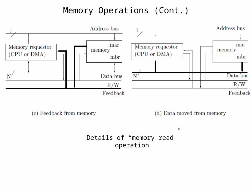
• Signals move between the CPU and memory on groups of wires called buses. A computer bus is a group of wires (or printed connections) carrying signals of the same type.
• Three buses were used in the following figure; The address bus, carrying the j bits of an address, the data bus, carrying the N bits of a word or a register, and the control bus, with R, W, and Feedback lines.
Memory Operations (Cont.)
Memory Operations (Cont.)
Details of “memory read” operation

• Memory write is, of course, different from memory read, but not significantly. The steps are:– MAR←address.– MBR←data.– “W”– wait.
• The steps are different and a “W” (write) signal is necessary. However, the main difference between the read and write sequences is the wait period.
• During memory read, the memory requestor must wait. During a memory write, however, since the wait period is the last step, the requestor can—at least in principle—do something else. The idea is that in Step 4, while memory is busy with its internal operations, no new memory access can start.
• However, If the requestor does not need another memory access, it can continue and can perform an internal operation.
• For example, suppose that the control unit has initiated a memory write. During Step 4, the control unit can perform a register shift, which is an internal operation and does not involve memory.
• The following figure summarizes the steps of a memory write operation.
Memory Operations (Cont.)


Machine Instructions
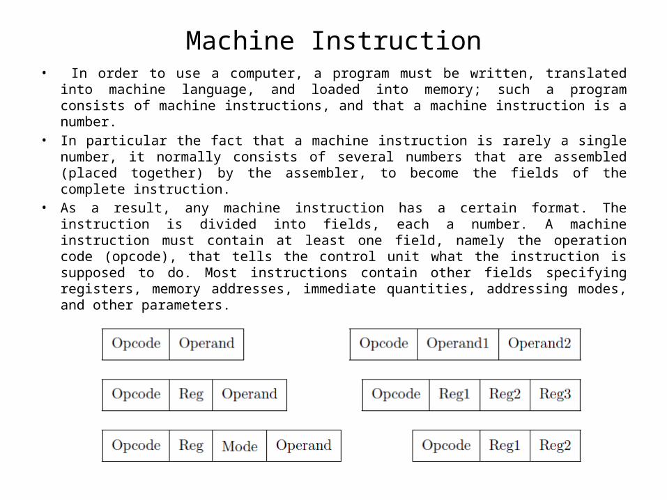
Machine Instruction• In order to use a computer, a program must be written, translated into machine
language, and loaded into memory; such a program consists of machine instructions, and that a machine instruction is a number.
• In particular the fact that a machine instruction is rarely a single number, it normally consists of several numbers that are assembled (placed together) by the assembler, to become the fields of the complete instruction.
• As a result, any machine instruction has a certain format. The instruction is divided into fields, each a number. A machine instruction must contain at least one field, namely the operation code (opcode), that tells the control unit what the instruction is supposed to do. Most instructions contain other fields specifying registers, memory addresses, immediate quantities, addressing modes, and other parameters.
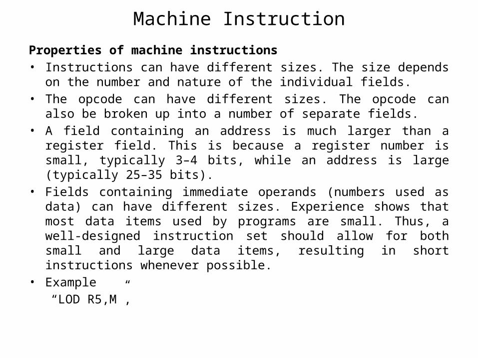
Properties of machine instructions• Instructions can have different sizes. The size depends on the number and
nature of the individual fields.• The opcode can have different sizes. The opcode can also be broken up
into a number of separate fields.• A field containing an address is much larger than a register field. This is
because a register number is small, typically 3–4 bits, while an address is large (typically 25–35 bits).
• Fields containing immediate operands (numbers used as data) can have different sizes. Experience shows that most data items used by programs are small. Thus, a well-designed instruction set should allow for both small and large data items, resulting in short instructions whenever possible.
• Example“LOD R5,M”,
Machine Instruction
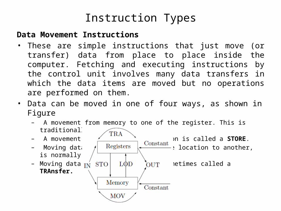
Instruction TypesData Movement Instructions• These are simple instructions that just move (or transfer) data from place
to place inside the computer. Fetching and executing instructions by the control unit involves many data transfers in which the data items are moved but no operations are performed on them.
• Data can be moved in one of four ways, as shown in Figure– A movement from memory to one of the register. This is traditionally called a LOAD.– A movement in the opposite direction is called a STORE.– Moving data inside memory, from one location to another, is normally called a MOVE.– Moving data between registers is sometimes called a TRAnsfer.

I/O Instructions• These instructions are divided into two groups, instructions that move
data, and control instructions. • The first group includes just two instructions, namely IN and OUT. Their
general format is “IN R,DEV” where R is any register and DEV is a device select number. Such an instruction moves one byte of data between the I/O device and the register.
• The second group consists of a number of instructions that send commands to the I/O devices and also receive device status. A control instruction may only send commands to a disk unit, or may only receive status from a keyboard.
• This is mostly true for modern computers, an I/O control instruction can be used to control several devices. An instruction such as “BRDY DEV,ADDR”, for example, reads status from device DEV and branches to location ADDR when a “ready” status is read.
Instruction Types (Cont.)
Instruction Types (Cont.)
N-Operand Instructions• These are instructions that differ by the number of their operands.• The ADD instruction, for example, is supposed to add two numbers, so it seems
that it should have two operands. • On many computers it is indeed a two–operand instruction, written as “ADD
R,ADDR” (add a memory location to a register) or “ADDR R1,R2” (add two registers).
• On some computers, however, the same instruction has only one operand and is therefore written “ADD ADDR”. Such an instruction adds its operand (a register or a memory location) to the accumulator (the main functional register).
• The LOD instruction, for instance, can have either one operand (LOD ADDR) or two operands (LOD R,ADDR).
• An instruction that moves a block of words in memory is a natural candidate for two operands. Thus “MOV SIZE,SOURCE,DESTIN” (that moves SIZE words from SOURCE to DESTIN) cannot be reasonably designed as a 1-operand or a 3-operand.
• Note that the SIZE operand is not really a third operand, since it is a short number and not an address. However, it is possible to design this instruction as “MOV SIZE,R1,R2” where the two registers point to the two memory areas.
Operations• These instructions specify operations on data items. They are all executed
in a similar way. The control unit fetches the two operands (or the single operand), sends them to the ALU, sends a function code to the ALU, and waits for the ALU to perform the operation. The control unit then picks up the result at the ALU and transfers it to its destination.
• There are three types of operations that can be performed on data items (numeric and non numeric), namely arithmetic operations, logical operations, and shifts.
• Arithmetic Operations• These include the four arithmetic operations on binary integers. However,
most modern computers have circuits in the ALU to operate on floating-point numbers, and sometimes also on BCD numbers, in addition to integers. Such a computer may have 12 circuits for arithmetic operations, four for each numeric data type. A few older computers had ALU circuits for calculating square roots.
Instruction Types (Cont.)
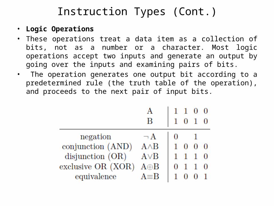
• Logic Operations• These operations treat a data item as a collection of bits, not as a number
or a character. Most logic operations accept two inputs and generate an output by going over the inputs and examining pairs of bits.
• The operation generates one output bit according to a predetermined rule (the truth table of the operation), and proceeds to the next pair of input bits.
Instruction Types (Cont.)
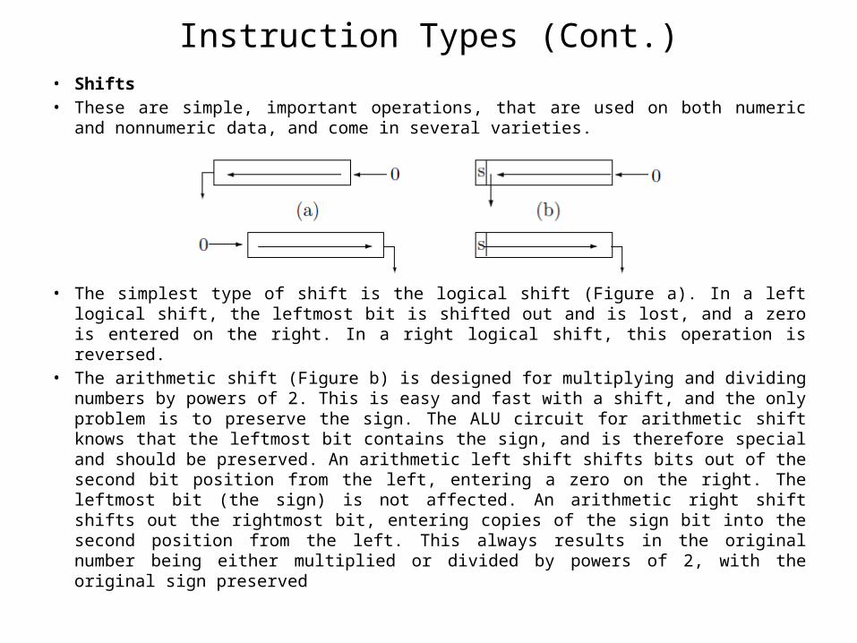
• Shifts• These are simple, important operations, that are used on both numeric and nonnumeric
data, and come in several varieties.
• The simplest type of shift is the logical shift (Figure a). In a left logical shift, the leftmost bit is shifted out and is lost, and a zero is entered on the right. In a right logical shift, this operation is reversed.
• The arithmetic shift (Figure b) is designed for multiplying and dividing numbers by powers of 2. This is easy and fast with a shift, and the only problem is to preserve the sign. The ALU circuit for arithmetic shift knows that the leftmost bit contains the sign, and is therefore special and should be preserved. An arithmetic left shift shifts bits out of the second bit position from the left, entering a zero on the right. The leftmost bit (the sign) is not affected. An arithmetic right shift shifts out the rightmost bit, entering copies of the sign bit into the second position from the left. This always results in the original number being either multiplied or divided by powers of 2, with the original sign preserved
Instruction Types (Cont.)
• Comparisons• In a typical comparison operation, two numbers are compared and a
result is generated. The result, however, is not a number, which is why comparisons are not considered operations on data, but are instead classified as a separate class of instructions. If the two numbers compared are a and b, then the result of the comparison is one of the three relations:
a < b, a = b, a > b.• The result is not a number and should therefore be stored in a special
place, not in a register or in memory.• Branches, Conditional and Unconditional• An unconditional branch is a simple, common instruction, executed by
resetting the PC to the branch address. This instruction is also called a jump, a transfer, or a goto. The importance of the conditional branches, however, is perhaps less obvious to the new programmer. The conditional branches turn out to be very important because they are the only way to perform decisions and loops in a program.
Instruction Types (Cont.)

• The programmer who is familiar with higher-level constructs such asif. . . then. . . else, do. . . while, repeat. . . until,
• is not always aware that the compiler uses the conditional branches as the only way to compile such constructs.
• A computer may have two types of conditional branches, jumps and branches. The only difference between them is the addressing mode. A jump uses the direct mode, and can jump anywhere in memory. A branch uses the relative mode, and can only jump over short distances
Instruction Types (Cont.)
Instruction Execution
Instruction Execution
• With this knowledge of the memory unit and its two operations, we are now ready to look at the details of how the control unit fetches and executes instructions.
• Fetching an instruction is a “memory read” operation. All instructions are fetched from memory in the same way, the only difference being the size of the instruction. In modern computers, some instructions are long. They occupy more than one memory word, and therefore have to be fetched in two or even three steps.
• Instruction execution, however, is different from fetching and decoding and is much more complex than the operations in Steps 1–4 of the control unit cycle. Modern computers can have a large instruction set with as many as 200–300 instructions.
• Some instructions are similar and are executed in very similar ways. Others are very different and are executed in completely different ways. In general, the control unit has to treat each instruction individually, and therefore has to contain a description of the execution of each instruction.
• The part of the control unit containing those descriptions is called the sequencer. This is the collection of all the execution circuits.
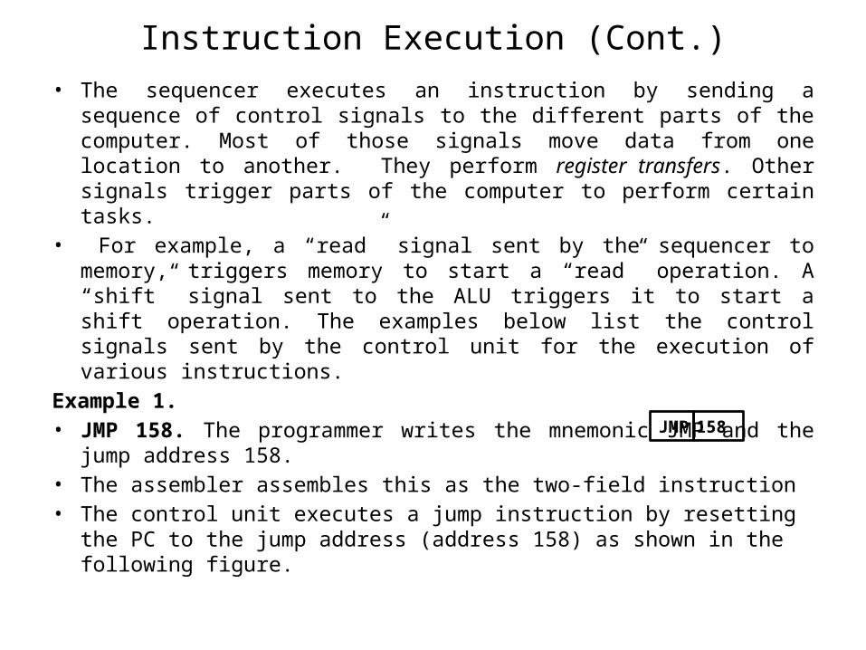
• The sequencer executes an instruction by sending a sequence of control signals to the different parts of the computer. Most of those signals move data from one location to another. They perform register transfers. Other signals trigger parts of the computer to perform certain tasks.
• For example, a “read” signal sent by the sequencer to memory, triggers memory to start a “read” operation. A “shift” signal sent to the ALU triggers it to start a shift operation. The examples below list the control signals sent by the control unit for the execution of various instructions.
Example 1. • JMP 158. The programmer writes the mnemonic JMP and the jump
address 158.• The assembler assembles this as the two-field instruction• The control unit executes a jump instruction by resetting the PC to the
jump address (address 158) as shown in the following figure.
Instruction Execution (Cont.)
JMP 158
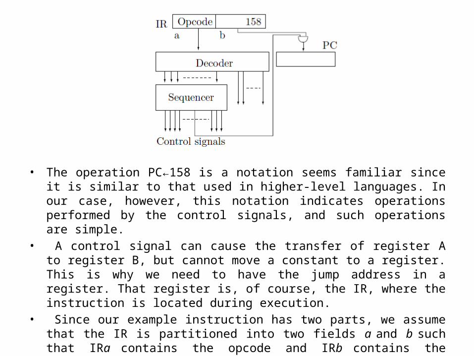
• The operation PC←158 is a notation seems familiar since it is similar to that used in higher-level languages. In our case, however, this notation indicates operations performed by the control signals, and such operations are simple.
• A control signal can cause the transfer of register A to register B, but cannot move a constant to a register. This is why we need to have the jump address in a register. That register is, of course, the IR, where the instruction is located during execution.
• Since our example instruction has two parts, we assume that the IR is partitioned into two fields a and b such that IRa contains the opcode and IRb contains the address. The only control signal necessary to execute the instruction can now be written as: PC ← IRb.

Example 2
• LOD R1,158. The programmer writes the mnemonic LOD, followed by the two operands (register and address) separated by a comma. The assembler generates the 3-field machine instruction
• We label these fields a, b, and c (where field IRb is the register number and field IRc contains the address). This instruction loads the content of memory location 158 into R1 (one of the GPRs, in the processor).
• Executing the instruction involves reading the operand from memory and moving it to the destination register. The steps are;– MAR ← IRc– “R”– wait– R1 ← MBR
• However, Step 4 cannot really be written in this form since these steps should be valid for any LOD instruction. Step 4 should therefore be general. Instead of using the explicit name of the destination register, it should get that name from field c of the IR. We can write this step
RIRb ←MBR.• The following figure shows the operation
LOD R1 158

Example 2 (Cont.)

Example 3
• ADD R1,158. This is similar to the previous example, and is illustrated in the following figure. Executing this instruction involves the steps:– Read one operand from memory and send it to the ALU.– Move the other operand from the register to the ALU.– Send a signal to the ALU to start adding.– Wait for the ALU to finish.
• Move the result (the sum) from the ALU output to its destination (the register).• The control signals are:
– MAR ← IRc– “R”– wait for memory– left-ALU←MBR– right-ALU← RIRb– “add”– wait for the ALU– RIRb ←ALU-output
• Notice the wait in Step 7. The processor is waiting for a feedback signal from the ALU, indicating that the ALU has completed the operation. This is similar to the feedback signal from memory.

Example 4
• LSHIFT R3,4. The content of register 3 is to be shifted four positions to the left. The way the programmer writes this instruction is obvious. The assembler assembles it as the 3-field number
• To execute this instruction, the control unit should move R3 to the ALU, start the ALU on the shift operation, wait for a feedback signal, and move the result back to the register. The control signals needed are;– left-ALU← RIRb– right-ALU← IRc– ALU-function← ‘left shift’– wait for ALU– RIRb ←ALU-output
• Note that the details of this process are transparent to the programmer. The programmer thinks of the shift as taking place in R3. Notice also the similarity between this example and the previous one. The difference between the execution of an add and a shift is in the ALU operation, the signals sent by the control unit are very similar.
LSHIFT R3 4

CPU Bus Structure
CPU Bus Structure
• The discussion in the previous section implies that data can be moved freely inside the CPU between the control unit, registers, and ALU. This section shows the details.
• Data is moved inside the CPU along buses that connect the three components, and there are two ways of organizing these buses, referred to as a single
• bus and triple bus.• A single-bus CPU is shown in Figure *a. Every piece of data is moved over the
single data bus, and the control unit sends register-transfer control signals on the control bus to open the right gates and move the data from source to destination.
• A point to note is that the ALU requires two inputs. One is sent to the auxiliary register and the other stays on the data bus during the ALU operation. Thus, sending input to the ALU requires two steps. The ALU result is latched in a result register and is sent to the data bus when the ALU has finished.
• The advantage of this CPU organization is that only one bus is needed. However, some auxiliary registers are required and some operations require more than one step.

• The triple-bus CPU design is shown in Figure *b The control unit and the registers can send data to, and receive data from, any of the three data buses. The ALU receives its two operands from data buses A and B, and sends its output to data bus C. There is no need for any auxiliary registers but three buses are needed.

Execute Simple Arithmetic Operation
• Add R1, R2, R0 This instruction adds the contents of source registers R1 and R2, and stores the results in destination register R0. This addition can be executed as follows:– The registers R0 , R1 , R2 , are extracted from the IR.– The contents of R1 and R2 are passed to the ALU for addition.– The output of the ALU is transferred to R0 .
• Using the one-bus datapath shown in Figure, this addition will take three steps as shown in the following table, where t0 < t1 < t2 .
Step Micro-operationt0 A (R1)t1 B (R2)t2 R0 (A) + (B)

• Using the two-bus datapath shown in Figure a, this addition will take two steps as shown in the following table, where t0 , t1 .
Step Micro-operationt0 A (R1) + (R2)t1 R0 (A)
• Using the three-bus datapath shown in Figure , this addition will take only one step as shown in the following table.
Step Micro-operationt0 R0 = (R1) + (R2)
Execute Simple Arithmetic Operation (Cont.)
Interrupts• Interrupts are the way the computer responds to urgent or unusual
conditions.• Mechanism by which other modules may interrupt the normal processing
of the CPU• Examples of such conditions are:
– Invalid opcode: When the control unit decodes the current instruction, it may find that the opcode is invalid (i.e., unused). On many computers, not all opcodes are used. Some opcodes do not correspond to any instruction and are considered invalid. When the control unit identifies such an opcode, it generates an interrupt, since this is both an unusual and an urgent condition. It has to be handled immediately and the program cannot continue as usual.
– Zero-divide: When the ALU starts executing a “divide” instruction, it first tests the divisor. If the divisor is zero, the ALU generates an interrupt since this is an urgent condition; the division cannot take place.
– Timer: On many computers, there is a timer that can be set, by software, to any time interval. When execution time reaches this interval, the timer senses it and generates an interrupt.
– Software interrupt. When the program wants to communicate with the operating system, it can artificially generate an interrupt. This interrupt is called a break, a software interrupt, or a supervisor call. It is an important feature of the computer and is discussed later in this section.
– Many hardware problems, such as a parity error (in memory or during I/O) or a drop in the voltage can cause interrupts, if the computer is equipped with the appropriate sensors to sense those conditions and to respond accordingly.
– I/O interrupts. Those are generated by an I/O device or by the I/O processor. Such an interrupt indicates that an I/O process has completed or that an I/O problem has been detected.
• A good way to understand interrupts is to visualize a number of interrupt request lines (IRQs) arriving at the control unit from various sources in the computer. When any interrupt source decides to interrupt the control unit, it sends a signal on its IRQ line. The control unit should test those lines from time to time to discover all pending interrupts, and respond to them.
Interrupts

• Testing the IRQ lines is done in a new step, Step 6 of the fetch-execute cycle. The cycle becomes:– 1. Fetch.– 2. Increment PC.– 3. Decode.– 4. Execute.– 6. Test all IRQ lines. If any of them is high, perform the following:
• 6.1 Save the PC.• 6.2 Set the PC to a memory address, depending on the interrupt.• 6.3 Disable all interrupts.• 6.4 Set processor mode to ‘system’.
Interrupts


![CSC 142 I 1 CSC 142 Iterations [Reading: chapter 6]](https://static.fdocuments.in/doc/165x107/56649f1b5503460f94c30888/csc-142-i-1-csc-142-iterations-reading-chapter-6.jpg)