CS8351 DIGITAL PRINCIPLES AND SYSTEM DESIGN UNIT I …
143
CS8351 DIGITAL PRINCIPLES AND SYSTEM DESIGN UNIT I BOOLEAN ALGEBRA AND LOGIC GATES Prof G ELANGOVAN Professor and Head Department of Electrical and Electronics Engineering NPR College of Engineering and Technology Natham, Dindigul Dist. 624 401 [email protected] 1
Transcript of CS8351 DIGITAL PRINCIPLES AND SYSTEM DESIGN UNIT I …

CS8351 DIGITAL PRINCIPLES AND SYSTEM DESIGN
UNIT I BOOLEAN ALGEBRA AND LOGIC GATES
Prof G ELANGOVAN Professor and Head
Department of Electrical and Electronics Engineering NPR College of Engineering and Technology
Natham, Dindigul Dist. 624 401
1

Books • M. Morris R. Mano, Michael D. Ciletti, ―Digital
Design: With an Introduction to the Verilog HDL, VHDL, and SystemVerilog‖, 6th Edition, Pearson Education, 2017
• Charles H. Roth Jr, Larry L. Kinney, Fundamentals of Logic Design, Sixth Edition, CENGAGE Learning, 2013
• John F. Wakerly, Digital Design Principles and Practices, Fifth Edition, Pearson Education, 2017.
2

UNIT I BOOLEAN ALGEBRA AND LOGIC GATES • Number Systems • Arithmetic Operations • Binary Codes • Boolean Algebra and Logic Gates • Theorems and Properties of Boolean Algebra • Boolean Functions • Canonical and Standard Forms • Simplification of Boolean Functions using
Karnaugh Map • Logic Gates • NAND and NOR Implementations
3

Number Systems
• Introduction
• Digital Systems and Binary Numbers
• Analog and Digital Signal
• Decimal Number System
• Octal Number System
• Binary Number System
• Hexadecimal Number System
• Number Base Conversions
4

Introduction • Digital systems
• Uses/Applications
• Characteristic
• The signals in most present‐day electronic digital systems use just two discrete values and are therefore said to be binary.
• A binary digit, called a bit, has two values: 0 and 1.
• Discrete elements of information are represented with groups of bits called binary codes.
5

• Digital Signal : Decimal values are difficult to represent in electrical systems. It is easier to use two voltage values than ten.
• Digital Signals have two basic states: 1 (logic “high”, or H, or “on”)
0 (logic “low”, or L, or “off”)
• Digital values are in a binary format. Binary means 2 states.
• A good example of binary is a light (only on or off)
on off
Power switches have labels “1” for on and “0” for off.
6

• Bits and Pieces of Digital History
• George Boole • Mathematical Analysis of Logic (1847)
• An Investigation of Laws of Thoughts; Mathematical Theories of Logic
and Probabilities (1854)
• Claude Shannon • Rediscovered the Boole
• “ A Symbolic Analysis of Relay and Switching Circuits “
• Boolean Logic and Boolean Algebra were Applied to Digital Circuitry
---------- Beginning of the Digital Age and/or Computer Age
World War II
Computers as Calculating Machines
Arlington (State Machines) “ Control “
7

Motivation • Microprocessors/Microelectronics have revolutionized
our world – Cell phones, internet, rapid advances in medicine, etc.
• The semiconductor industry has grown tremendously
8

Digital Systems and Binary Numbers
Digital age and information age Digital computers
– General purposes – Many scientific, industrial and commercial applications
• Digital systems – Telephone switching exchanges – Digital camera – Electronic calculators, PDA's – Digital TV
• Discrete information-processing systems – Manipulate discrete elements of information – For example, ,1, 2, 3, …- and ,A, B, C, …-…
9

Analog and Digital Signal
• Analog system
– The physical quantities or signals may vary continuously over a specified range.
• Digital system
– The physical quantities or signals can assume only discrete values.
– Greater accuracy
t
X(t)
t
X(t)
Analog signal Digital signal 10

Analog Digital
Technology: Analog technology records waveforms as they are.
Converts analog waveforms into set of numbers and records them. The numbers are converted into voltage stream for representation.
Uses: Can be used in various computing platforms and under operating systems like Linux, Unix, Mac OS and Windows.
Computing and electronics
Signal:
Analog signal is a continuous signal which transmits information as a response to changes in physical phenomenon.
Digital signals are discrete time signals generated by digital modulation.
Representation: Uses continuous range of values to represent information.
Uses discrete or discontinuous values to represent information.
Memory unit: not required required
applications: Thermometer PCs, PDAs
Data transmissions:
not of high quality high quality
Result: not very accurate accurate
Storage capacity: limited high
Process: processed using OPAMP which uses electronic circuits
using microprocessor which uses logic circuits
Respose to Noise:
More likely to get affected reducing accuracy
Less affected since noise response are analog in nature
Waves: Denoted by sine waves Denoted by square waves
Example: human voice in air electronic devices
11

Binary Digital Signal • An information variable represented by
physical quantity. • For digital systems, the variable takes on
discrete values. – Two level, or binary values are the most
prevalent values.
• Binary values are represented abstractly by: – Digits 0 and 1 – Words (symbols) False (F) and True (T) – Words (symbols) Low (L) and High (H) – And words On and Off
• Binary values are represented by values or ranges of values of physical quantities.
t
V(t)
Binary digital signal
Logic 1
Logic 0
undefine
12

Decimal Number System • Base (also called radix) = 10
– 10 digits { 0, 1, 2, 3, 4, 5, 6, 7, 8, 9 }
• Digit Position
– Integer & fraction
• Digit Weight
– Weight = (Base) Position
• Magnitude
– Sum of “Digit x Weight”
• Formal Notation
1 0 -1 2 -2
5 1 2 7 4
10 1 0.1 100 0.01
500 10 2 0.7 0.04
d2*B2+d1*B
1+d0*B
0+d-1*B
-1+d-2*B
-2
(512.74)10
13

Octal Number System • Base = 8
– 8 digits { 0, 1, 2, 3, 4, 5, 6, 7 }
• Weights
– Weight = (Base) Position
• Magnitude
– Sum of “Digit x Weight”
• Formal Notation
1 0 -1 2 -2
8 1 1/8 64 1/64
5 1 2 7 4
5 *82+1 *8
1+2 *8
0+7 *8
-1+4 *8
-
2
=(330.9375)10
(512.74)8
14

Binary Number System • Base = 2
– 2 digits { 0, 1 }, called binary digits or “bits”
• Weights
– Weight = (Base) Position
• Magnitude
– Sum of “Bit x Weight”
• Formal Notation
• Groups of bits 4 bits = Nibble
8 bits = Byte
1 0 -1 2 -2
2 1 1/2 4 1/4
1 0 1 0 1
1 *22+0 *2
1+1 *2
0+0 *2
-1+1 *2
-
2
=(5.25)10
(101.01)2
1 0 1 1
1 1 0 0 0 1 0 1 15

Hexadecimal Number System • Base = 16
– 16 digits { 0, 1, 2, 3, 4, 5, 6, 7, 8, 9, A, B, C, D, E, F }
• Weights
– Weight = (Base) Position
• Magnitude
– Sum of “Digit x Weight”
• Formal Notation
1 0 -1 2 -2
16 1 1/16
256 1/256
1 E 5 7 A
1 *162+14 *16
1+5 *16
0+7 *16
-1+10 *16
-2
=(485.4765625)10
(1E5.7A)16
16

The Power of 2 n 2n
0 20=1
1 21=2
2 22=4
3 23=8
4 24=16
5 25=32
6 26=64
7 27=128
n 2n
8 28=256
9 29=512
10 210=1024
11 211=2048
12 212=4096
20 220=1M
30 230=1G
40 240=1T
Mega
Giga
Tera
Kilo
17

? ? ?
(365)8 = ( x ) 10
X = 3*64 + 6*8 + 5 *1
= 192 + 48 + 5
= 24510
18

Addition • Decimal Addition
5 5
5 5 +
0 1 1
= Ten ≥ Base
Subtract a Base
1 1 Carry
19

Binary Addition • Column Addition
1 0 1 1 1 1
1 1 1 1 0 +
0 0 0 0 1 1 1
≥ (2)10
1 1 1 1 1 1
= 61
= 23
= 84
20

Binary Subtraction • Borrow a “Base” when needed
0 0 1 1 1 0
1 1 1 1 0 −
0 1 0 1 1 1 0
= (10)2
2
2
2 2
1
0 0 0
1
= 77
= 23
= 54
21

Binary Multiplication • Bit by bit
0 1 1 1 1
0 1 1 0
0 0 0 0 0
0 1 1 1 1
0 1 1 1 1
0 0 0 0 0
0 1 1 0 1 1 1 0
x
22

Number Base Conversions
Decimal
(Base 10)
Octal
(Base 8)
Binary
(Base 2)
Hexadecimal
(Base 16)
Evaluate Magnitude
Evaluate Magnitude
Evaluate Magnitude 23

Decimal (Integer) to Binary Conversion
• Divide the number by the ‘Base’ (=2)
• Take the remainder (either 0 or 1) as a coefficient
• Take the quotient and repeat the division Example: (13)10 Quotient Remainder Coefficient
Answer: (13)10 = (a3 a2 a1 a0)2 = (1101)2
MSB LSB
13 / 2 = 6 1 a0 = 1
6 / 2 = 3 0 a1 = 0
3 / 2 = 1 1 a2 = 1
1 / 2 = 0 1 a3 = 1
24

Decimal (Fraction) to Binary Conversion
• Multiply the number by the ‘Base’ (=2)
• Take the integer (either 0 or 1) as a coefficient
• Take the resultant fraction and repeat the division
Example: (0.625)10 Integer Fraction Coefficient
Answer: (0.625)10 = (0.a-1 a-2 a-3)2 = (0.101)2
MSB LSB
0.625 * 2 = 1 . 25
0.25 * 2 = 0 . 5 a-2 = 0
0.5 * 2 = 1 . 0 a-3 = 1
a-1 = 1
25

Decimal to Octal Conversion Example: (175)10
Quotient Remainder Coefficient
Answer: (175)10 = (a2 a1 a0)8 = (257)8
175 / 8 = 21 7 a0 = 7
21 / 8 = 2 5 a1 = 5
2 / 8 = 0 2 a2 = 2
Example: (0.3125)10
Integer Fraction Coefficient
Answer: (0.3125)10 = (0.a-1 a-2 a-3)8 = (0.24)8
0.3125 * 8 = 2 . 5
0.5 * 8 = 4 . 0 a-2 = 4
a-1 = 2
26

Binary − Octal Conversion • 8 = 23
• Each group of 3 bits represents an octal digit
Octal Binary
0 0 0 0
1 0 0 1
2 0 1 0
3 0 1 1
4 1 0 0
5 1 0 1
6 1 1 0
7 1 1 1
Example:
( 1 0 1 1 0 . 0 1 )2
( 2 6 . 2 )8
Assume Zeros
Works both ways (Binary to Octal & Octal to Binary)
27

Binary − Hexadecimal Conversion • 16 = 24
• Each group of 4 bits represents a hexadecimal digit
Hex Binary 0 0 0 0 0
1 0 0 0 1
2 0 0 1 0
3 0 0 1 1
4 0 1 0 0
5 0 1 0 1
6 0 1 1 0
7 0 1 1 1
8 1 0 0 0
9 1 0 0 1
A 1 0 1 0
B 1 0 1 1
C 1 1 0 0
D 1 1 0 1
E 1 1 1 0
F 1 1 1 1
Example: ( 1 0 1 1 0 . 0 1 )2
( 1 6 . 4 )16
Assume Zeros
Works both ways (Binary to Hex & Hex to Binary)
28

Octal − Hexadecimal Conversion • Convert to Binary as an intermediate step
Example:
( 0 1 0 1 1 0 . 0 1 0 )2
( 1 6 . 4 )16
Assume Zeros
Works both ways (Octal to Hex & Hex to Octal)
( 2 6 . 2 )8
Assume Zeros
29

Decimal, Binary, Octal and Hexadecimal Decimal Binary Octal Hex
00 0000 00 0
01 0001 01 1
02 0010 02 2
03 0011 03 3
04 0100 04 4
05 0101 05 5
06 0110 06 6
07 0111 07 7
08 1000 10 8
09 1001 11 9
10 1010 12 A
11 1011 13 B
12 1100 14 C
13 1101 15 D
14 1110 16 E
15 1111 17 F
30
Number Systems - Coclusion
Introduction
Digital Systems and Binary Numbers
Analog and Digital Signal
Decimal Number System
Octal Number System
Binary Number System
Hexadecimal Number System
Number Base Conversions
31

Complements • There are two types of complements for each base-r system: the radix complement and diminished
radix complement. • Diminished Radix Complement - (r-1)’s Complement
– Given a number N in base r having n digits, the (r–1)’s complement of N is defined as:
(rn –1) – N • Example for 6-digit decimal numbers:
– 9’s complement is (rn – 1)–N = (106–1)–N = 999999–N – 9’s complement of 546700 is 999999–546700 = 453299
• Example for 7-digit binary numbers:
– 1’s complement is (rn – 1) – N = (27–1)–N = 1111111–N – 1’s complement of 1011000 is 1111111–1011000 = 0100111
• Observation:
– Subtraction from (rn – 1) will never require a borrow – Diminished radix complement can be computed digit-by-digit – For binary: 1 – 0 = 1 and 1 – 1 = 0
32

Complements • 1’s Complement (Diminished Radix Complement)
– All ‘0’s become ‘1’s
– All ‘1’s become ‘0’s
Example (10110000)2
(01001111)2
If you add a number and its 1’s complement …
1 0 1 1 0 0 0 0
+ 0 1 0 0 1 1 1 1
1 1 1 1 1 1 1 1
33
Complements
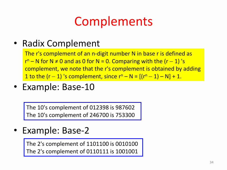
• Radix Complement
• Example: Base-10
• Example: Base-2
The r's complement of an n-digit number N in base r is defined as rn – N for N ≠ 0 and as 0 for N = 0. Comparing with the (r 1) 's complement, we note that the r's complement is obtained by adding 1 to the (r 1) 's complement, since rn – N = [(rn 1) – N] + 1.
The 10's complement of 012398 is 987602 The 10's complement of 246700 is 753300
The 2's complement of 1101100 is 0010100 The 2's complement of 0110111 is 1001001
34

Complements • 2’s Complement (Radix Complement)
– Take 1’s complement then add 1
– Toggle all bits to the left of the first ‘1’ from the right
Example:
Number:
1’s Comp.:
0 1 0 1 0 0 0 0
1 0 1 1 0 0 0 0
0 1 0 0 1 1 1 1
+ 1
OR
1 0 1 1 0 0 0 0
0 0 0 0 1 0 1 0
35

Complements
• Subtraction with Complements
– The subtraction of two n-digit unsigned numbers M – N in base r can be done as follows:
36
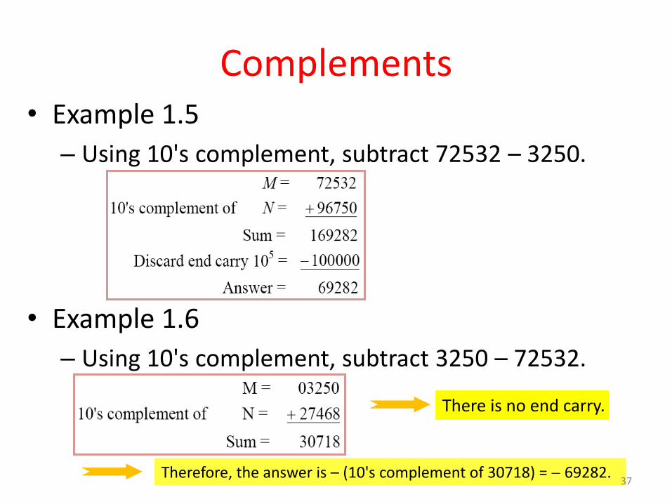
Complements • Example 1.5
– Using 10's complement, subtract 72532 – 3250.
• Example 1.6
– Using 10's complement, subtract 3250 – 72532.
There is no end carry.
Therefore, the answer is – (10's complement of 30718) = 69282. 37

Complements • Example 1.7
– Given the two binary numbers X = 1010100 and Y = 1000011, perform the subtraction (a) X – Y ; and (b) Y X, by using 2's complement.
There is no end carry. Therefore, the answer is Y – X = (2's complement of 1101111) = 0010001.
38

Complements • Subtraction of unsigned numbers can also be done by means of the (r 1)'s
complement. Remember that the (r 1) 's complement is one less then the r's complement.
• Example 1.8
– Repeat Example 1.7, but this time using 1's complement.
There is no end carry, Therefore, the answer is Y – X = (1's complement of 1101110) = 0010001.
39

Signed Binary Numbers
• To represent negative integers, we need a notation for negative values.
• It is customary to represent the sign with a bit placed in the leftmost position of the number since binary digits.
• The convention is to make the sign bit 0 for positive and 1 for negative.
• Example:
• Table 1.3 lists all possible four-bit signed binary numbers in the three representations.
40

Signed Binary Numbers
41

Signed Binary Numbers • Arithmetic addition
– The addition of two numbers in the signed-magnitude system follows the rules of ordinary arithmetic. If the signs are the same, we add the two magnitudes and give the sum the common sign. If the signs are different, we subtract the smaller magnitude from the larger and give the difference the sign if the larger magnitude.
– The addition of two signed binary numbers with negative numbers represented in signed-2's-complement form is obtained from the addition of the two numbers, including their sign bits.
– A carry out of the sign-bit position is discarded.
• Example:
42

Signed Binary Numbers
• Arithmetic Subtraction – In 2’s-complement form:
• Example:
1. Take the 2’s complement of the subtrahend (including the sign bit)
and add it to the minuend (including sign bit).
2. A carry out of sign-bit position is discarded.
( ) ( ) ( ) ( )
( ) ( ) ( ) ( )
A B A B
A B A B
( 6) ( 13) (11111010 11110011)
(11111010 + 00001101)
00000111 (+ 7) 43

Binary Codes Digital data is represented, stored and transmitted as groups of binary digits also known as binary code. Weighted codes: In weighted codes, each digit is assigned a specific weight according to its position. Non-weighted codes: In non-weighted codes are not appositionally weighted. Reflective codes: A code is reflective when the code is self complementing. In other words, when the code for 9 is the complement the code for 0, 8 for 1, 7 for 2, 6 for 3 and 5 for 4. Sequential codes: In sequential codes, each succeeding 'code is one binary number greater than its preceding code. Alphanumeric codes: Codes used to represent numbers, alphabetic characters, symbols Error defecting and correcting codes: Codes which allow error defection and correction are called error detecting and' correcting codes.
44

• BCD Code – A number with k decimal digits will
require 4k bits in BCD. – Decimal 396 is represented in BCD with
12bits as 0011 1001 0110, with each group of 4 bits representing one decimal digit.
– A decimal number in BCD is the same as its equivalent binary number only when the number is between 0 and 9.
– The binary combinations 1010 through 1111 are not used and have no meaning in BCD.
Example: Consider decimal 185 and its corresponding value in BCD and binary:
BCD addition
45

Binary Codes • Other Decimal Codes
46

Binary Codes • Gray Code
– The advantage is that only bit in the code group changes in going from one number to the next. • Error detection.
• Representation of analog data.
• Low power design.
000 001
010
100
110 111
101 011
1-1 and onto!! 47

• American Standard Code for Information Interchange (ASCII) Character Code
48

• ASCII Character Code
49

ASCII Character Codes and Properties
• American Standard Code for Information Interchange (Refer to Table 1.7)
• A popular code used to represent information sent as character-based data.
• It uses 7-bits to represent:
– 94 Graphic printing characters.
– 34 Non-printing characters.
• Some non-printing characters are used for text format (e.g. BS = Backspace, CR = carriage return).
• Other non-printing characters are used for record marking and flow control (e.g. STX and ETX start and end text areas).
• ASCII has some interesting properties:
– Digits 0 to 9 span Hexadecimal values 3016 to 3916
– Upper case A-Z span 4116 to 5A16
– Lower case a-z span 6116 to 7A16 • Lower to upper case translation (and vice versa) occurs by flipping bit 6.
50

• Error-Detecting Code
– To detect errors in data communication and processing, an eighth bit is sometimes added to the ASCII character to indicate its parity.
– A parity bit is an extra bit included with a message to make the total number of 1's either even or odd.
• Example:
– Consider the following two characters and their even and odd parity:
51

• Error-Detecting Code – Redundancy (e.g. extra information), in the form of extra bits, can be
incorporated into binary code words to detect and correct errors.
– A simple form of redundancy is parity, an extra bit appended onto the code word to make the number of 1’s odd or even. Parity can detect all single-bit errors and some multiple-bit errors.
– A code word has even parity if the number of 1’s in the code word is even.
– A code word has odd parity if the number of 1’s in the code word is odd.
– Example:
10001001
10001001
1
0 (odd parity) Message B:
Message A: (even parity)
52

Hamming Codes • Invented W.B Hamming and Simple 1parity bit can tell us an error occurred
• Multiple parity bits can also tell us where it occurred
• O(lg(n)) bits needed to detect and correct one bit errors.
• In generally we use 7 bits hamming code – 4 data bits/message bit (m) and 3 parity bits (2P>= P+m+1)
Example: Byte 1011 0001
Two data blocks, 1011 and 0001.
Expand the first block to 7 bits: _ _ 1 _ 0 1 1.
Bit 1 is 0, because b3+b5+b7 is even.
Bit 2 is 1, b3+b6+b7 is odd.
bit 4 is 0, because b5+b6+b7 is even.
Our 7 bit block is: 0 1 1 0 0 1 1
Repeat for right block giving 1 1 0 1 0 0 1
Error detectings: 0 1 1 0 1 1 1 Re-Check each parity bit
Bits 1 and 4 are incorrect
1 + 4 = 5, so the error occurred in bit 5
53

Binary Storage and Registers
• Registers – A binary cell is a device that possesses two stable states and is capable of storing
one of the two states. – A register is a group of binary cells. A register with n cells can store any discrete
quantity of information that contains n bits.
• A binary cell – Two stable state – Store one bit of information – Examples: flip-flop circuits, ferrite cores, capacitor
• A register – A group of binary cells – AX in x86 CPU
• Register Transfer – A transfer of the information stored in one register to another. – One of the major operations in digital system. – An example in next slides.
n cells 2n possible states
54

Binary Logic • Definition of Binary Logic
– Binary logic consists of binary variables and a set of logical operations.
– The variables are designated by letters of the alphabet, such as A, B, C, x, y, z, etc, with each variable having two and only two distinct possible values: 1 and 0,
– Three basic logical operations: AND, OR, and NOT.
55

Binary Logic gates
• Truth Tables, Boolean Expressions, and Logic Gates
xy z
x y z
0 0 0
0 1 0
1 0 0
1 1 1
x y z
0 0 0
0 1 1
1 0 1
1 1 1
x z
0 1
1 0
AND OR NOT
xy z
z = x • y = x y z = x + y z = x = x’
x z


Universal Gate • NAND and NOR Gates are called Universal Gates because AND, OR
and NOT gates can be implemented &created by using these gates.
NAND Gate Implementations NOR Gate Implementations

Binary Logic
• Logic gates
– Example of binary signals
0
1
2
3 Logic 1
Logic 0
Un-define
Figure 1.3 Example of binary signals 59

Binary Logic
• Logic gates
– Graphic Symbols and Input-Output Signals for Logic gates:
Fig. 1.4 Symbols for digital logic circuits
Fig. 1.5 Input-Output signals for gates 60

Binary Logic
• Logic gates
– Graphic Symbols and Input-Output Signals for Logic gates:
Fig. 1.6 Gates with multiple inputs
61

Boolean Algebra Boolean Algebra : George Boole(English mathematician), 1854 Invented by George Boole in 1854 An algebraic structure defined by a set B = {0, 1}, together with two binary
operators (+ and ·) and a unary operator ( ) “An Investigation of the Laws of Thought, on Which Are Founded the Mathematical Theories of Logic
and Probabilities”
Boolean Algebra
{(1,0), Var, (NOT, AND, OR), Thms}
Mathematical tool to expression and analyze digital (logic) circuits
Claude Shannon, the first to apply Boole’s work, 1938 – “A Symbolic Analysis of Relay and Switching Circuits” at MIT
This chapter covers Boolean algebra, Boolean expression and its evaluation and simplification, and VHDL program
62

Boolean functions : NOT, AND, OR,
exclusive OR(XOR) : odd function exclusive NOR(XNOR) : even function(equivalence)
Basic Functions and Basic Functions
Basic functions • AND Z=X Y or Z=XY
Z=1 if and only if X=1 and Y=1, otherwise Z=0
• OR Z=X + Y
Z=1 if X=1 or if Y=1, or both X=1and Y=1. Z=0 if and only if X=0 and Y=0
• NOT Z=X or
Z=1 if X=0, Z=0 if X=1 63

64

Boolean Operations and Expressions
• Boolean Addition
–Logical OR operation
Ex 4-1) Determine the values of A, B, C, and D that make the sum term A+B’+C+D’
Sol) all literals must be ‘0’ for the sum term to be ‘0’
A+B’+C+D’=0+1’+0+1’=0 A=0, B=1, C=0, and D=1
• Boolean Multiplication
–Logical AND operation
Ex 4-2) Determine the values of A, B, C, and D for AB’CD’=1
Sol) all literals must be ‘1’ for the product term to be ‘1’
AB’CD’=10’10’=1 A=1, B=0, C=1, and D=0
65

Basic Identities of Boolean Algebra
The relationship between a single variable X, its complement X, and the binary constants 0 and 1
66

Consensus Theorem
• Consensus Theorem In simplification of Boolean expression, an expression
of the form AB+ A’C+ BC the term BC is redundant and can be eliminated to
form the equivalent expression AB+ A’C. The theorem used for this simplification is known as consensus theorem and is stated as,
AB+ A’C+ BC = AB+ A’C The dual form of consensus theorem is stated as, (A+B) (A’+C) (B+C) = (A+B) (A’+C)
67

Laws of Boolean Algebra
• Commutative Law: the order of literals does not matter
A + B = B + A A B = B A
• Associative Law: the grouping of literals does not matter A + (B + C) = (A + B) + C (=A+B+C) A(BC) = (AB)C (=ABC)
Distributive Law : A(B + C) = AB + AC (A+B)(C+D) = AC + AD + BC + BD
68

A+0=A In math if you add 0 you have changed nothing in
Boolean Algebra ORing with 0 changes nothing
A•0=0 In math if 0 is multiplied with anything you get 0. If you AND anything with 0 you get 0
A•1 =A ANDing anything with 1 will yield the anything
A+A = A ORing with itself will give the same result
A+A’=1 Either A or A’ must be 1 so A + A’ =1
A•A = A ANDing with itself will give the same result
A•A’ =0 In digital Logic 1’ =0 and 0’ =1, so AA’=0 since one of the inputs must be 0.
A = (A’)’ If you not something twice you are back to the beginning
Rules of Boolean Algebra
69

A + A’B = A + B
If A is 1 the output is 1 If A is 0 the output is B
A + AB = A
(A + B)(A + C) = A + BC
• DeMorgan’s Theorem
– F(A,A, , + , 1,0) = F(A, A, + , ,0,1)
– (A • B)’ = A’ + B’ and (A + B)’ = A’ • B’
– DeMorgan’s theorem will help to simplify digital circuits using NORs and NANDs his theorem states
70

Boolean Analysis of Logic Circuits • Constructing a Truth Table for a Logic Circuit
– Convert the expression into the min-terms containing all the input literals
– Get the numbers from the min-terms
– Putting ‘1’s in the rows corresponding to the min-terms and ‘0’s in the remains
Ex) A(B+CD)=AB(C+C’) (D+D’) +A(B+B’)CD =ABC(D+D’) +ABC’(D+D’) +ABCD+AB’CD =ABCD+ABCD’+ABC’D+ABC’D’ +ABCD+AB’CD =ABCD+ABCD’+ABC’D+ABC’D’ +AB’CD =m11+m12+m13+m14+m15=(11,12,13,14,15)
A(B+CD) = m11+m12+m13+m14+m15 =(11,12,13,14,15)
71

Standard Forms of Boolean Expressions
The Sum-of-Products(SOP) Form Ex) AB+ABC, ABC+CDE+B’CD’ The Product-of-Sums(POS) Form Ex) (A+B)(A+B+C), (A+B+C)(C+D+E)(B’+C+D’)
Principle of Duality : SOP POS Domain of a Boolean Expression : The set of variables contained in the expression
Ex) A’B+AB’C : the domain is ,A, B, C-
Standard SOP Form (Canonical SOP Form)
– For all the missing variables, apply (x+x’)=1 to the AND terms of the expression
– List all the min-terms in forms of the complete set of variables in ascending order
Ex : Convert the following expression into standard SOP form: AB’C+A’B’+ABC’D
Sol) domain=,A,B,C,D-, AB’C(D’+D)+A’B’(C’+C)(D’+D)+ABC’D =AB’CD’+AB’CD+A’B’C’D’+A’B’C’D+A’B’CD’+A’B’CD+ABC’D =1010+1011+0000+0001+0010+0011+1101 =0+1+2+3+10+11+13 = (0,1,2,3,10,11,13)
72

Standard POS Form (Canonical POS Form)
– For all the missing variables, apply (x’x)=0 to the OR terms of the expression
– List all the max-terms in forms of the complete set of variables in ascending order
Ex : Convert the following expression into standard POS form: (A+B’+C)(B’+C+D’)(A+B’+C’+D)
Sol) domain={A,B,C,D}, (A+B’+C)(B’+C+D’)(A+B’+C’+D) =(A+B’+C+D’D)(A’A+B’+C+D’)(A+B’+C’+D) =(A+B’+C+D’)(A+B’+C+D)(A’+B’+C+D’)(A+B’+C+D’)(A+B’+C’+D)=(0100) )(0101)(0110)(1101)= (4,5,6,13)
73
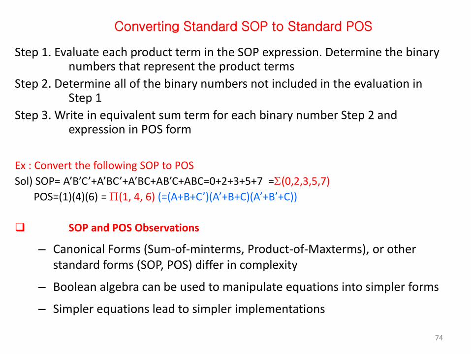
Converting Standard SOP to Standard POS
Step 1. Evaluate each product term in the SOP expression. Determine the binary numbers that represent the product terms
Step 2. Determine all of the binary numbers not included in the evaluation in Step 1
Step 3. Write in equivalent sum term for each binary number Step 2 and expression in POS form
Ex : Convert the following SOP to POS
Sol) SOP= A’B’C’+A’BC’+A’BC+AB’C+ABC=0+2+3+5+7 =(0,2,3,5,7)
POS=(1)(4)(6) = (1, 4, 6) (=(A+B+C’)(A’+B+C)(A’+B’+C))
SOP and POS Observations
– Canonical Forms (Sum-of-minterms, Product-of-Maxterms), or other standard forms (SOP, POS) differ in complexity
– Boolean algebra can be used to manipulate equations into simpler forms
– Simpler equations lead to simpler implementations
74

Summary of Minterms and Maxterms
• There are 2n minterms and maxterms for Boolean functions with n variables.
• Minterms and maxterms are indexed from 0 to 2n – 1
• Any Boolean function can be expressed as a logical sum of minterms and as a logical product of maxterms
• The complement of a function contains those minterms not included in the original function
• The complement of a sum-of-minterms is a product-of-maxterms with the same indices
Dual of a Boolean Expression
• To changing 0 to 1 and + operator to – vise versa for a given boolean function
Example: F = (A + C) · B + 0
dual F = (A · C + B) · 1 = A · C + B
Example: G = X · Y + (W + Z)
dual G =
Unless it happens to be self-dual, the dual of an expression does not equal the
expression itself
Are any of these functions self-dual? (A+B)(A+C)(B+C)=(A+BC)(B+C)=AB+AC+BC
75

• The minterms and maxterms of a 3- variable function can be represented as
Variables Minterms Maxterms x y z mi Mi 0 0 0 x’y’z’ = m0 x+ y+ z= M0 0 0 1 x’y’z = m1 x+ y+ z’= M1 0 1 0 x’yz’ = m2 x+ y’+ z= M2 0 1 1 x’yz = m3 x+ y’+ z’= M3 1 0 0 xy’z’ = m4 x’+ y+ z= M4 1 0 1 xy’z = m5 x’+ y+ z’= M5 1 1 0 xyz’ = m6 x’+ y’+ z= M6 1 1 1 xyz = m7 x’+ y’+ z’= M7 76

Minimization of Boolean Expressions
• The Boolean expressions can be simplified by applying properties, laws and theorems of Boolean algebra
• Simplify the following Boolean functions to a minimum number of literals
1. x (x’+y)
= xx’+ xy * x. x’= 0 +
= 0 + xy [ x+ 0 = x ]
= xy.
77

2. x+ x’y
= x + xy + x’y [ x+ xy= x]
= x+ y (x+x’)
= x+ y (1) * x+ x’ = 1+
= x+ y.
3. (x+ y) (x+ y’)
= x.x+ xy’+ xy+ yy’
= x+ xy’+ xy+ 0 * x. x= 0+; * y. y’= 0+
= x (1+ y’+ y)
= x (1) [ 1+y= 1 ]
= x.
78

4. xy + x’z + yz.
= xy + x’z + yz( x+ x’) * x+ x’= 1+
= xy + x’z + xyz + x’yz
Re-arranging,
= xy + xyz + x’z +x’yz
= xy (1+ z) + x’z (1+y) [1+y= 1]
= xy+ x’z.
5. xy+ yz+ y’z
= xy+ z ( y+ y’)
= xy+ z ( 1 ) * y+ y’ = 1+
= xy+ z. 79

6. (x+ y) (x’+ z) (y+ z) = (x+ y) (x’+ z)
[ dual form of consensus theorem, (A+ B) (A’+ C) (B+ C) = (A+ B) (A’+ C) + 7. x’y+ xy+ x’y’ = y ( x’+ x) + x’y’ [ x (y+ z) = xy+ xz ] = y ( 1 ) + x’y’ * x+ x’ = 1+ = y+ x’y’ [ x+ x’y’ = x+ y’ + = y+ x’. 8. x+ xy’+ x’y = x (1+ y’)+ x’y = x (1) + x’y [ 1+ x = 1 ] = x+ x’y [ x+ x’y = x+ y ] = x+ y. 80

9. AB + (AC)' + AB’C (AB + C) = AB + (AC)' + AAB'BC + AB'CC = AB + (AC)' + 0+ AB'CC [B.B' = 0] = AB + (AC)' + AB'C [C.C = 1] = AB + A' + C' +AB'C [(AC)' = A' + C'] = AB + A’ + C' + AB‚ *C’ + AB’C = C’ + AB’+ = A' + B+ C’+ AB’ *A’ + AB = A’ + B+ Re- arranging, = A' + AB’+ B+ C' *A’ + AB = A’ + B+ = A' + B’+ B+ C' * B’+ B= 1+ = A' +1+ C’ [ A+ 1= 1] = 1
81

10. (x’+ y) (x+ y)
= x’.x+ x’y+ yx+ y.y
= 0+ x’y+ xy+ y [ x.x’= 0+; * x. x= x+
= y ( x’+ x+ 1)
= y( 1 ) [ 1+ x = 1 ]
= y.
11. xy+ xyz+ xyz’+ x’yz
= xy ( 1+ z+ z’)+ x’yz
= xy ( 1 ) + x’yz [ 1+ x = 1 ]
= xy+ x’yz
= y ( x+ x’z ) [ x+ x’y = x+ y]
= y ( x+ z ). 82

12. x’y’z’+ x’yz’+ xy’z’+ xyz’ = x’z’ (y’+ y)+ xz’ (y’+ y) = x’z’+ xz’ * x+ x’= 1+ = z’ (x’+ x) = z’ * x+ x’= 1+ 13. w’xyz’+ xyz’+ xy’z’+ xy’z = xyz’ (w’+ 1) + xy’z’+ xy’z = xyz’+ xy’z’+ xy’z [ 1+ x = 1 ] = xz’ (y+ y’) + xy’z = xz’+ xy’z * x+ x’= 1+ = x (z‘+ y’z) = x (z’+ y’). * x’+ xy’ = x’+ y’+
83

14. [ xy+ xz+’+ x’y’z
= (xy)’. (xz)’+ x’y’z
= (x’+ y’). (x’+ z’)+ x’y’z
= x’x’+ x’z’+ x’y’+ y’z’+ x’y’z
= x’+ x’z’+ x’y’+ y’z’+ x’y’z [x+ x= x]
= x’+ x’z’+ x’y’+ y’ *z’+ x’z]
= x’+ x’z’+ x’y’+ y’ *z’+ x’+ * x’+ xy = x’+ y+
= x’+ x’y’+ y’ *z’+ x’+ *x+ xy = x]
= x’+ x’y’+ y’z’+ x’y’
= x’+ y’z’+ x’y’ [x+ xy = x]
= x’+ y’z’. [x+ xy = x]
84

Find the complement of the following functions
1. F= x’yz’+ x’y’z
F’= (x’yz’+ x’y’z)’
= (x”+ y’+ z”) . (x”+ y”+z’)
= (x+ y’+ z). (x+ y+ z’).
2. F= x (y’z’+ yz)
F’= *x (y’z’+ yz)+’
= x’+ (y’z’+ yz)’
= x’+ (y’z’)’. (yz)’
= x’+ (y”+ z”) . (y’+ z’)
= x’+ (y+ z) . (y’+ z’). 85

3. F= (xy + y’z + xz) x. F’ = *(xy + y’z + xz) x+’ = (xy + y’z + xz)’ + x’ = [(xy)’ . (y’z)’. (xz)’+ + x’ = [(x’+y’). (y+z’). (x’+z’)+ + x’ = [(x’y+ x’z’+ 0+ y’z’) ( x’+z’)+ + x’ = x’x’y+ x’x’z’+ x’y’z’+ x’yz’+ x’z’z’+ y’z’z’+ x’ = x’y+ x’z’+ x’y’z’+ x’yz’+ x’z’+ y’z’+ x’ [x+ x = x], [x. x = x] = x’y+ x’z’+ x’z’ (y’+ y) + y’z’+ x’ *x+ x’= 1+ = x’y+ x’z’+ x’z’ (1) + y’z’+ x’ = x’y+ x’z’+ y’z’+ x’ = x’y+ x’+ x’z’+ y’z’ = x’(y+1) + x’z+ y’z’ [y+1= 1] = x’ (1+z) + y’z’ [y+1= 1] = x’+ y’z’
86

Karnaugh Map
• Simplification methods – Boolean algebra(algebraic method)
– Karnaugh map(map method))
– Quine-McCluskey(tabular method)
– Three- and Four-input Kanaugh maps
XY+XY=X(Y+Y)=X
Gray code
87

88

89

Example) F(X,Y,Z)=m(2,3,4,5) =XY+XY Example) F(X,Y,Z)=m(0,2,4,6) = XZ+XZ =Z(X+X)=Z
Karnaugh Map (K- Map) Steps
1. Sketch a Karnaugh map grid for the given problem.in power of 2N Squares
2. Fill in the 1’s and 0’s from the truth table of sop or pos Boolean function 3. Circle groups of 1’s.
Circle the largest groups of 2, 4, 8, etc. first. Minimize the number of circles but make sure that every 1 is in a
circle. 4. Write an equation using these circles.
90

Grouping Two Adjacent 1’s: (Pair)
91

Grouping Four Adjacent 1’s: (Quad)
92

Grouping Eight Adjacent 1’s: (Octet)
93

Simplification of Sum of Products Expressions: (Minimal Sums)
• The generalized procedure to simplify Boolean expressions as follows:
1. Plot the K-map and place 1’s in those cells corresponding to the 1’s in the sum of product expression. Place 0’s in the other cells.
2. Check the K-map for adjacent 1’s and encircle those 1’s which are not adjacent to any other 1’s. These are called isolated 1’s.
3. Check for those 1’s which are adjacent to only one other 1 and encircle such pairs.
4. Check for quads and octets of adjacent 1’s even if it contains some 1’s that have already been encircled. While doing this make sure that there are minimum number of groups.
5. Combine any pairs necessary to include any 1’s that have not yet been grouped.
6. Form the simplified expression by summing product terms of all the groups.
94

Three- Variable Map
1. Simplify the Boolean expression,
F(x, y, z) = Σm (3, 4, 6, 7).
F = yz+ xz’
95

2. F(x, y, z) = Σm (0, 2, 4, 5, 6).
F = z’+ xy’
96

3. F = A’C + A’B + AB’C + BC Soln: = A’C (B+ B’) + A’B (C+ C’) + AB’C + BC (A+ A’) = A’BC+ A’B’C + A’BC + A’BC’ + AB’C + ABC + A’BC = A’BC+ A’B’C + A’BC’ + AB’C + ABC = m3+ m1+ m2+ m5+ m7 = Σ m (1, 2, 3, 5, 7) F = C + A’B
97

4. AB’C + A’B’C + A’BC + AB’C’ + A’B’C’ Soln: = m5 + m1 + m3 + m4 + m0 = Σ m (0, 1, 3, 4, 5) F = A’C + B’
98

Four - Variable Map: Simplify the Boolean expression, 1. Y = A’BC’D’ + A’BC’D + ABC’D’ + ABC’D + AB’C’D +
A’B’CD’ Y= A’B’CD’+ AC’D+ BC’
99

2. F (w, x, y, z) = Σ m(0, 1, 2, 4, 5, 6, 8, 9, 12, 13, 14)
F= y’+ w’z’+ xz’
100

3. F= A’B’C’+ B’CD’+ A’BCD’+ AB’C’ = A’B’C’ (D+ D’) + B’CD’ (A+ A’) + A’BCD’+ AB’C’ (D+ D’)
= A’B’C’D+ A’B’C’D’+ AB’CD’+ A’B’CD’+ A’BCD’+ AB’C’D+ AB’C’D’
= m1+ m0+ m10+ m2+ m6+ m9+ m8
= Σ m (0, 1, 2, 6, 8, 9, 10)
F= B’D’+ B’C’+ A’CD’. 101

4. Y= ABCD+ AB’C’D’+ AB’C+ AB = ABCD+ AB’C’D’+ AB’C (D+D’)+ AB (C+C’) (D+D’) = ABCD+ AB’C’D’+ AB’CD+ AB’CD’+ (ABC+ ABC’) (D+ D’) = ABCD+ AB’C’D’+ AB’CD+ AB’CD’+ ABCD+ ABCD’+ ABC’D+ ABC’D’ = ABCD+ AB’C’D’+ AB’CD+ AB’CD’+ ABCD’+ ABC’D+ ABC’D’
= m15+ m8+ m11+ m10+ m14+ m13+ m12 = Σ m (8, 10, 11, 12, 13, 14, 15) Y= AB+ AC+ AD’.
102

5. Y (A, B, C, D)= Σ m (7, 9, 10, 11, 12, 13, 14, 15)
Y= AB+ AC+ AD+BCD.
103

6. Y= A’B’C’D+ A’BC’D+ A’BCD+ A’BCD’+ ABC’D+ ABCD+ AB’CD = m1+ m5+ m7+ m6+ m13+ m15+ m11 = Σ m (1, 5, 6, 7, 11, 13, 15) In the above K-map, the cells 5, 7, 13 and 15 can be grouped
to form a quad as indicated by the dotted lines. In order to group the remaining 1’s, four pairs have to be formed. However, all the four 1’s covered by the quad are also covered by the pairs. So, the quad in the above k-map is redundant.
Therefore, the simplified expression will be, Y = A’C’D+ A’BC+ ABD+ ACD.
104

7. Y= Σ m (1, 5, 10, 11, 12, 13, 15)
Y= A’C’D+ ABC’+ ACD+ AB’C.
105

8. Y= A’B’CD’+ ABCD’+ AB’CD’+ AB’CD+ AB’C’D’+ ABC’D’+ A’B’CD+ A’B’C’D’
Y= AD’+ B’C+ B’D’
106

9. F (A, B, C, D) = Σ m (0, 1, 4, 8, 9, 10)
F= A’C’D’+ AB’D’+ B’C’.
107

Simplification of Product of Sums Expressions: (Minimal Products)
1. Y= (A+ B+ C’) (A+ B’+ C’) (A’+ B’+ C’) (A’+ B+ C) (A+ B+ C)
= M1. M3. M7. M4. M0 =Π M (0, 1, 3, 4, 7)
= Σ m (2, 5, 6)
Y’ = B’C’+ A’C+BC.
Y = Y” = (B’C’+ A’C+ BC)’ = (B’C’)’. (A’C)’. (BC)’
= (B”+ C”). (A”+C’). (B’+ C’)
Y = (B+ C). (A+C’). (B’+ C’) 108

2. Y= (A’+ B’+ C+ D) (A’+ B’+ C’+ D) (A’+ B’+ C’+ D’) (A’+ B+ C+ D) (A+ B’+ C’+ D) (A+ B’+ C’+ D’) (A+ B+ C+ D) (A’+ B’+ C+ D’)
= M12. M14. M15. M8. M6. M7. M0. M13 = ΠM (0, 6, 7, 8, 12, 13, 14, 15)
Y’ = B’C’D’+ AB+ BC Y= Y” = (B’C’D’+ AB+ BC)’ = (B’C’D’)’. (AB)’. (BC)’ = (B”+ C”+D”). (A’+B’). (B’+ C’) = (B+ C+ D). (A’+ B’). (B’+ C’) Therefore, Y= (B+ C+ D). (A’+ B’). (B’+ C’) 109

3. F(A, B, C, D)= ΠM (0, 2, 3, 8, 9, 12, 13, 15)
Y’ = A’B’D’+ A’B’C+ ABD+ AC’
Y= Y” = (A’B’D’+ A’B’C+ ABD+ AC’)’
= (A’B’D’)’. (A’B’C)’. (ABD)’. (AC’)’
= (A”+ B”+ D”). (A”+ B”+C’). (A’+ B’+ D’). (A’+ C”)
Y = (A+ B+ D). (A+ B+ C’). (A’+ B’+ D’). (A’+ C) 110

4. F(A, B, C, D)= Σm (0, 1, 2, 5, 8, 9, 10)
= ΠM (3, 4, 6, 7, 11, 12, 13, 14, 15)
Y’ = BD’+ CD+ AB
Y= Y” = (BD’+ CD+ AB)’
= (BD’)’. (CD)’. (AB)’
= (B’+ D”). (C’+ D’). (A’+ B’)
Y = (B’+ D). (C’+ D’). (A’+ B’) 111

Don’t care Conditions • A don’t care minterm is a combination of
variables whose logical value is not specified.
• When choosing adjacent squares to simplify the function in a map, the don’t care minterms may be assumed to be either 0 or 1.
• When simplifying the function, we can choose to include each don’t care minterm with either the 1’s or the 0’s, depending on which combination gives the simplest expression.
112

1. F (x, y, z) = Σm (0, 1, 2, 4, 5)+ Σd (3, 6, 7)
F (x, y, z) = 1
113

2. F (w, x, y, z) = Σm (1, 3, 7, 11, 15)+ Σd (0, 2, 5)
F (w, x, y, z) = w’x’+ yz
114

3. F (w, x, y, z) = Σm (0, 7, 8, 9, 10, 12)+ Σd (2, 5, 13)
F (w, x, y, z) = w’xz+ wy’+ x’z’.
115

4. F (w, x, y, z) = Σm (0, 1, 4, 8, 9, 10)+ Σd (2, 11)
F (w, x, y, z) = wx’+ x’y’+ w’y’z’.
116

5. F( A, B, C, D) = Σm (0, 6, 8, 13, 14)+ Σd (2, 4, 10)
F( A, B, C, D) = CD’+ B’D’+ ABC’D
117
ABC’D

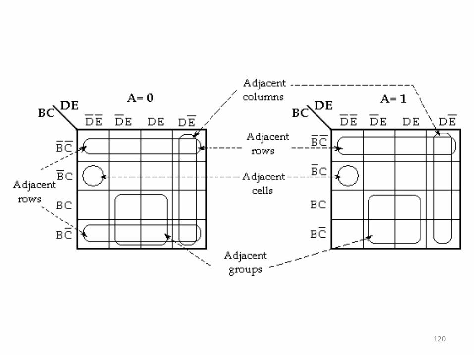
Five- Variable Maps • A 5- variable K- map requires 25 = 32 cells, but adjacent cells are
difficult to identify on a single 32-cell map. Therefore, two 16 cell K-maps (Two 4 variable) are used.
• If the variables are A, B, C, D and E, two identical 16- cell maps containing B, C, D and E can be constructed. One map is used for A and other for A’.
• In order to identify the adjacent grouping in the 5- variable map, we must imagine the two maps superimposed on one another ie., every cell in one map is adjacent to the corresponding cell in the other map, because only one variable changes between such corresponding cells
• Thus, every row on one map is adjacent to the corresponding row (the one occupying the same position) on the other map, as are corresponding columns. Also,
• the rightmost and leftmost columns within each 16- cell map are adjacent, just as they are in any 16- cell map, as are the top and bottom rows. 118

119
120

1. Simplify the Boolean function
F (A, B, C, D, E) = Σm (0, 2, 4, 6, 9, 11, 13, 15, 17, 21, 25, 27, 29, 31)
F (A, B, C, D, E) = A’B’E’+ BE+ AD’E 121
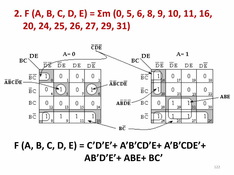
2. F (A, B, C, D, E) = Σm (0, 5, 6, 8, 9, 10, 11, 16, 20, 24, 25, 26, 27, 29, 31)
F (A, B, C, D, E) = C’D’E’+ A’B’CD’E+ A’B’CDE’+ AB’D’E’+ ABE+ BC’
122

3. F (A, B, C, D, E) = Σm ( 1, 4, 8, 10, 11, 20, 22, 24, 25, 26)+Σd (0, 12, 16, 17)
F (A, B, C, D, E) = B’C’D’+ A’D’E’+ BC’E’+ A’BC’D+ AC’D’+ AB’CE’
123

4. F (A, B, C, D, E) = Σm (0, 1, 2, 6, 7, 9, 12, 28, 29, 31)
F (A, B, C, D, E) = BCD’E’+ ABCE+ A’B’C’E’+ A’C’D’E+ A’B’CD
124

5. F (x1, x2, x3, x4, x5) = Σm (2, 3, 6, 7, 11, 12, 13, 14, 15, 23, 28, 29, 30, 31 )
F (x1, x2, x3, x4, x5) = x2x3+ x3x4x5+ x1’x2’x4+ x1’x3’x4x5
125

6. F (x1, x2, x3, x4, x5) = Σm (1, 2, 3, 6, 8, 9, 14, 17, 24, 25, 26, 27, 30, 31 )+ Σd (4, 5)
F (x1, x2, x3, x4, x5) = x2x3’x4’+ x2x3x4x5’+ x3’x4’x5+ x1x2x4+ x1’x2’x3x5’+ x1’x2’x3’x4
126

LOGIC GATES
127

128
NAND AND NOR IMPLEMENTATION
• Digital circuits are frequently constructed with NAND or NOR gates rather than with AND and OR gates.
• NAND and NOR gates are easier to fabricate with electronic components and are the basic gates used in all IC digital logic families.
129

NAND Circuits • The NAND gate is said to be a universal gate because
any logic circuit can be implemented with it.
• To show that any Boolean function can be implemented with NAND gates, we need only show that the logical operations of AND, OR, and complement can be obtained with NAND gates alone.
Three-input NAND gate
130

• A convenient way to implement a Boolean function with NAND gates is to obtain the simplified Boolean function in terms of Boolean operators and then convert the function to NAND logic.
• The conversion of an algebraic expression from AND, OR, and complement to NAND can be done by simple circuit manipulation techniques that change AND–OR diagrams to NAND diagrams.
• The implementation of Boolean functions with NAND gates requires that the functions be in sum-of-products form.
131

Two-Level Implementation
• F = AB + CD
132

Implement the following Boolean function with NAND gates:
F (x, y, z) = (1, 2, 3, 4, 5, 7)
K-Map
F = xy + xy + z
133

• The procedure for obtaining the logic diagram from a Boolean function is as follows:
1. Simplify the function and express it in sum-of-products form.
2. Draw a NAND gate for each product term of the expression that has at least two literals. The inputs to each NAND gate are the literals of the term. This procedure produces a group of first-level gates.
3. Draw a single gate using the AND-invert or the invert-OR graphic symbol in the second level, with inputs coming from outputs of first-level gates.
4. A term with a single literal requires an inverter in the first level. However, if the single literal is complemented, it can be connected directly to an input of the second level NAND gate.
134

Multilevel NAND Circuits
F = A (CD + B) + BC
135

• The general procedure for converting a multilevel AND–OR diagram into an all-NAND diagram using mixed notation is as follows:
1. Convert all AND gates to NAND gates with AND-invert graphic symbols.
2. Convert all OR gates to NAND gates with invert-OR graphic symbols.
3. Check all the bubbles in the diagram. For every bubble that is not compensated by another small circle along the same line, insert an inverter (a one-input NAND gate) or complement the input literal.
136

• F = (AB + AB)(C + D)
137

NOR Implementation
Logic operations with NOR gates
138

F = (A + B)(C + D)E
F = (AB + AB)(C + D) with NOR gates 139

Quine-McCluskey - Tabular Method
• Step 1 − Arrange the given min terms in an ascending order and make the groups based on
the number of ones present in their binary representations. - ‘n+1’ groups
• Step 2 − Compare the min terms present in successive groups. If there is a change in only
one-bit position, then take the pair of those two min terms. Place this symbol ‘_’ in the
differed bit position and keep the remaining bits as it is.
• Step 3 − Repeat step2 with newly formed terms till we get all prime implicants.
• Step 4 − Formulate the prime implicant table. It consists of set of rows and columns. Place
‘1’ in the cells corresponding to the min terms that are covered in each prime implicant.
• Step 5 − Find the essential prime implicates by observing each column. Those essential
prime implicants will be part of the simplified Boolean function.
• Step 6 − Reduce the prime implicant table by removing the row of each essential prime
implicant and the columns corresponding to the min terms that are covered in that essential
prime implicant. Repeat step 5 for Reduced prime implicant table. Stop this process when
all min terms of given Boolean function are over.
140

141

142

End of Unit I
143