Is Android the New Embedded Embedded Linux? at Embedded World 2013

© Kavi Arya 1
CS684 Embedded Systems
(Software)
Kavi Arya
CSE/ IIT Bombay
Models and Tools for Embedded Systems

© Kavi Arya 2
Problems with FSMs • All is not well with FSMs • FSMs fine for small systems (10s of states) • Imagine FSM with 100s and 1020 of states
which is a reality • Such large descriptions difficult to understand • FSMs are flat and no structure • Inflexible to add additional functionalities • Need for structuring and combining different
state machines

© Kavi Arya 3
Statecharts • Extension of FSMs to have these features • Due to David Harel • Retains the nice features
– Pictorial appeal – States and transitions
• Enriched with two features – Hierarchy and Concurrency
• States are of two kinds – OR state (Hierarchy) – AND state (concurrency)

© Kavi Arya 4
OR States • An OR state can have a whole state machine inside it • Example:

© Kavi Arya 5
OR states • When the system is in the state Count, it is
either in counting or not_counting • Exactly in ONE of the inner states • Hence the term OR states
(more precisely XOR state) • When Count is entered, it will enter
not_counting – default state
• Inner states can be OR states (or AND states)

© Kavi Arya 6
OR states • Both outer and inner states active simultaneously • When the outer state exits, inner states also exited • Priorities of transitions • Preemption (strong and weak)

© Kavi Arya 7
Economy of Edges
• Every transition from outer state corresponds to many transitions from each of the inner states
• Hierarchical construct replaces all these into one single transition
• Edge labels can be complex

© Kavi Arya 8
AND States • An Or state contains exactly one state machine • An And state contains two or more state machines • Example:

© Kavi Arya 9
Example • Counting is an And state w/ 3 state machines • S1, S2, S3, concurrent components of state • When in state Counting, control resides
simultaneously in all 3 state machines • Initially, control is in C0, B0 and A0 • Execution involves, in general, simultaneous
transitions in all the state machines

© Kavi Arya 10
Example (contd.) • When in state C0, B0, A1, clock signal triggers
the transition to B1 and A0 in S2 and S3 • When in C0, B1, A1, clock signal input trigger the
transitions to C1, B0 and A0 in all S1, S2, S3 • And state captures concurrency • Default states in each concurrent component

© Kavi Arya 11
Economy of States • AND-state can be flattened to single state mc • Results in exponential number of states and
transitions • AND state is compact & intuitive representation

© Kavi Arya 12
Counting • What are the three components of the state? • They represent behaviour of three bits of a counter • S3 –least significant bit, S2 the middle and S1 is MSB • Compare this with flat and monolithic description of
counter state machine given earlier • Which is preferable? • The present one is robust - can be redesigned to
accommodate additional bits • Look at the complete description of the counter

© Kavi Arya 13
Complete Machine

© Kavi Arya 14
Communication • Concurrent components of AND state communicate
with each other • Taking an edge requires certain events to occur • New signals are generated when an edge is taken • These can trigger further transitions in other
components • A series of transitions can be taken as a result of one
transition triggered by environment event • Different kinds of communication primitives • More on this later

© Kavi Arya 15
Flat State Machines • Capture the behaviour of the counter using FSMs
– Huge number of states and transitions – Explosion of states and transitions
• Statechart description is compact – Easy to understand – Robust – Can be simulated – Code generation is possible – Execution mechanism is more complex

© Kavi Arya 16
Exercise • Extend the lift controller example
– Control for closing and opening the door – Control for indicator lamp – Avoid movement of the lift when the door is open – Include states to indicate whether the lift is in
service or not – Controller for multiple lifts
• Give a Statechart description

© Kavi Arya 17
Extensions to Statecharts • Various possibilities explored • Adding code to transitions, to states • Complex data types and function calls • Combining textual programs with statecharts • Various commercial tools exist
– Statemate and Rhapsody (ilogix) – UML tools (Rational rose) – Stateflow (Mathworks) – SynchCharts (Esterel Technologies)
© Kavi Arya 18
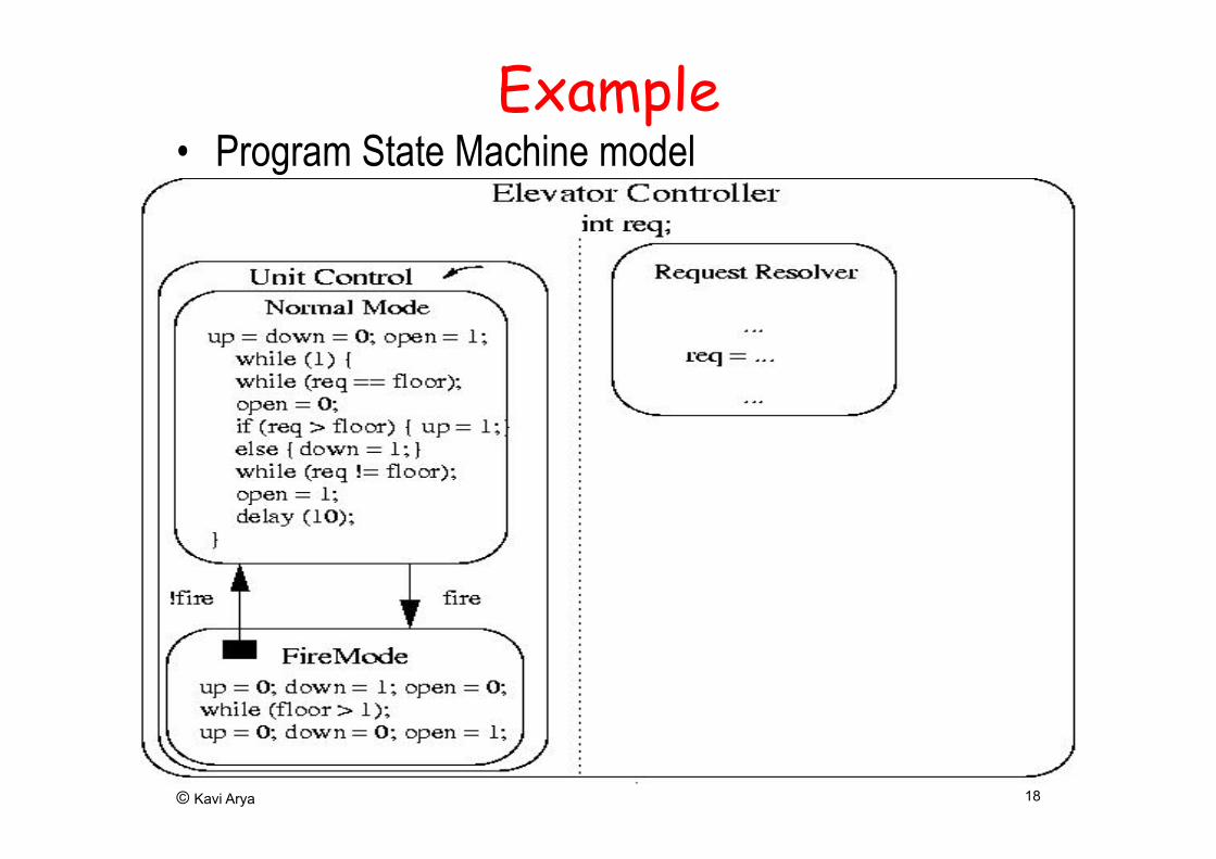
Example • Program State Machine model

© Kavi Arya 19
Fuel Controller

© Kavi Arya 20
Fuel Controller (Contd.)

© Kavi Arya 21
More Exercises • Construct the State machine models of
– Critical Section Problem – Producer-Consumer Problem – Dining Philosopher Problem
• And argue the correctness of solutions • Formal Analysis and Verification (more on
this later)

© Kavi Arya 22
Other Models • Synchronous Reactive Models
– Useful for expressing control dominated application – Rich primitives for expressing complex controls – Esterel (Esterel Technologies) – More on this later

© Kavi Arya
Issues in Teaching Model Based Design (ref. Valet Parking)
• Goal – Model Based Design using Project Based Learning
• Issues – Embedded Systems are platform specific – Translation from conceptual (problem) plane to
implementation on actual machine is a challenge – Little available in public domain (compare with Java)
or it’s expensive (Esterel, Lustre/SCADE, …) – Teaching design->reasoning->implementation is a
challenge

© Kavi Arya 24
Design Features • Two broad classifications
– Control-dominated designs – Data-dominated Designs
• Control-dominated designs – Input events arrive at irregular and unpredictable
times – Time of arrival and response more crucial than
values

© Kavi Arya 25
Design Features • Data-dominated designs
– Inputs are streams of data coming at regular intervals (sampled data)
– Values are more crucial – Outputs are complex mathematical functions of inputs – numerical computations and digital signal processing
computations

© Kavi Arya 26
• State machines, Statecharts, Esterel are good for control-dominated designs
• Data flow models for data-dominated systems • Special case of concurrent process models • System behaviour described as an interconnection
of nodes • Each node describes transformation of data • Connection between a pair of nodes describes the
flow of data from one node to the other
Data flow Models

© Kavi Arya 27
Example
+ -
*
modulate convolve
Transform
A B A C D B C D
t1 t2 t1 t2
B B

© Kavi Arya 28
Data Flow Models • Graphical Languages with support for
– Simulation, debugging, analysis – Code generation onto DSP and micro processors
• Analysis support for hardware-software partitioning
• Many commercial tools and languages – Lustre, Signal – SCADE – Matlab, Scilab

© Kavi Arya 29
Discrete Event Models • Used for HW systems • VHDL, Verilog • Models are interconnection of nodes • Each node reacts to events at their inputs • Generates output events which trigger other
nodes

© Kavi Arya 30
Discrete Event Models
• External events initiate a reaction • Delays in nodes modeled as delays in
event generation • Simulation • Problems with cycles • Delta cycles in VHDL

© Kavi Arya 31
A B
C
D
Discrete Event Models
D

© Kavi Arya 32

© Kavi Arya 33
Esterel: Motivation

© Kavi Arya 34
Embedded Software Typical structure of a simple embedded Software
loop
read inputs/sensors; compute response; generate actuator outputs
forever

© Kavi Arya 35
Embedded Software (contd.) • Design Decisions
– How to read inputs?
– How often to read inputs?
– Which order to read the inputs?
– How to compute responses?
– How to generate the responses?
– How often to generate?

© Kavi Arya 36
The Simplest Approach
Round Robin Scheme
loop await tick; read S1; take_action(S1); read S2; take_action(S2); read S3; take_action(S3); forever
Tick is a time interrupt

© Kavi Arya 37
Problems • Processing speed decides the input rate! • Fine for interactive systems not for reactive
systems • But it should be the other way around:
– Characters coming at an network interface card – Video frame processing – Signals from pacemaker’s environment
• All sensors are treated identically – Some require urgent processing

© Kavi Arya 38
• System response function of respective inputs – In general, it depends upon all inputs and – On the history - state dependent
• Fragile scheme – More sensors - more processing delay
Problems

© Kavi Arya 39
BMW 745i : Prelude To Complexity
Another Life Cycle Example : The Software Error
© Kavi Arya 40
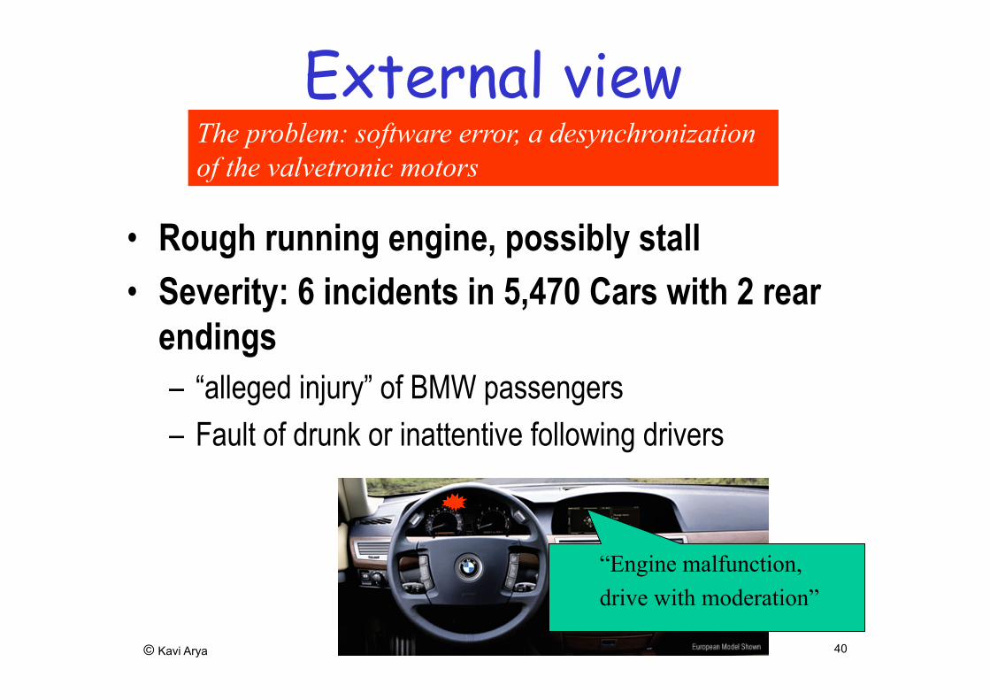
External view
• Rough running engine, possibly stall • Severity: 6 incidents in 5,470 Cars with 2 rear
endings – “alleged injury” of BMW passengers – Fault of drunk or inattentive following drivers
“Engine malfunction, drive with moderation”
The problem: software error, a desynchronization of the valvetronic motors

© Kavi Arya 41
Bosch EMU For Four Wheeler ( Multi Cylinder)
Source: Bosch Brochure : Ref 6
© Kavi Arya 42
The Most General Scheme • Task1 || Task2 || … || Task8 • Tasks
– Sequential threads – Concurrently executed – can be scheduled and suspended – wait for specific time period or events – communicate with each other

© Kavi Arya 43
The Most General Scheme • Real-time OS (RTOS kernel)
– Manages the tasks – Task communications – Timer services – Schedules the tasks for execution using various – Scheduling strategies

© Kavi Arya 44
Challenge with RTOS • Too much time and space overhead • More complex design • Writing and understanding concurrent
tasks very difficult • Race conditions, deadlocks, livelocks • Concurrency model is asynchronous • No timing guarantees

© Kavi Arya 45
Challenge with RTOS (contd.)
• Priorities, scheduling • System behavior highly unpredictable • Or building predictable system is very
challenging • Analysis very difficult • Thorough simulation required

© Kavi Arya 46
Synchronous Approach A novel Methodology • Originated from three French groups
– Through Esterel, Lustre, Signal • Basis for Statecharts, stateflow • Very successful in application domain
– Lustre in SCADE (Telelogic) • Aerospatiale - Airbus 340 and 385
(entirely designed using SCADE tool) • Schneider Electric for nuclear plants

© Kavi Arya 47
Synchronous Approach (contd.) – Esterel Technologies
• Rafale bomber (successor of Mirage) by Dassault Aviation • TI (DSP Chips), ST Microelectronics (DVD Chips) • Intel and Motorola use Esterel tools • Cadence Lab. (for HW design) • POLIS HW-SW Co-design
– SIGNAL • Snecma - airplane engines
– Statecharts in I-logix Tool • Developed for avionics application

© Kavi Arya 48
Main Features of Synchronous Approach
• A 3-level architecture 1. Interactive (I/O) interface 2. Reactive Kernel 3. Data Management
• Each level requires different kinds of processing
• Separation of concerns • Kernel is the most complex

© Kavi Arya 49
Synchronous Execution • Interface acquires inputs and forwards outputs,
– Interrupt processing, reading sensor values, – Conversion of logical and physical I/O
• Reactive kernel periodically executed – Computes logical outputs given logical inputs. – Execution is atomic – No change of inputs during execution – Reaction
• Data Management by conventional sequential functions – called by reactive kernel

© Kavi Arya 50
Synchrony Hypothesis
• Reaction is instantaneous • Abstraction: reaction time is insignificant
compared to the period • Reaction is atomic • This abstraction is realistic • Can be checked - loop free computation

© Kavi Arya 51
Synchrony Hypothesis
Other features: • provides rich set of constructs for
programming the kernel – Kernel is the most complex part – Interface, Data management programmed in
host language

© Kavi Arya 52
Synchrony Hypothesis (contd.)
• Multiform notion of time – Time like any other external event – Example:
• Train must stop within 50 meters • Alarm raised when gas overflow limit reached
• Kernel compiled into sequential automaton – No tasks and no scheduling overhead – No priorities, no race conditions
• Predictability is very high – delay 5 sec; delay 5 sec = delay 10 sec
© Kavi Arya 53
State Machines • State machines are flat with no structure • Esterel provides rich structure
– Large machines difficult to understand
Consider the specification: – Emit O as soon as inputs A and B arrive – Reset each time if input R occurs

© Kavi Arya 54
FSM Implementation:

© Kavi Arya 55
Esterel Implementation
• The code more compact than FSM • Each signal appears exactly once! • Statechart descriptions also more compact
module ABRO: input A,B,R; output O; loop do [ await A || await B ]; emit O watching R end
end module

© Kavi Arya 56
Esterel • An imperative language for programming
reactive kernels • It is a textual language! • An Example: Seat-Belt Controller • Here is a requirement:
" Five seconds after the key is turned on, if the belt has not been fastened, an alarm will beep for five seconds or until the key is turned off "

© Kavi Arya 57
module belt_control: input reset, key_on, key_off, belt_on, end_5, end_10; output alarm(boolean), start_timer; loop do emit alarm(false); every key_on do do emit start_timer; await end_5; emit alarm(true); await end_10; watching [key_off or belt_on]; emit alarm(false); end watching reset end
Esterel Solution

© Kavi Arya 58
Esterel Solution • Structure reflects closely the requirements • Constructs are high level
– loop, every, watching, emit, await • Sounds similar to informal language phrases • But having a precise semantics • Easy to see the correctness of solution • Nice syntactic structure • Compare it with the state machine solution

© Kavi Arya 59
Behavior of program:

© Kavi Arya 60
Layered Organization: Esterel View
Bare Machine I/O Handlers
Esterel Application Esterel Program + Data Handler

© Kavi Arya 61
Layer Interaction

© Kavi Arya 62
Some more exercise • Give a more detailed model of the digital
camera – Only certain data flow aspect of the camera is
given in the class (and in the book)

© Kavi Arya 63
Summary • Various models reviewed
– Sequential programming models – Hierarchical and Concurrent State Machines – Data Flow Models, Discrete Event Models
• Each model suitable for particular application • State Machines for event-oriented control systems • Sequential prog. model, data flow model for fcn computation • Real systems often require mixture of models • Modeling tools/ lang. should have combination of all the features
– Ptolemy (Berkeley) project studies modeling, simulation, and design of concurrent, real-time, embedded systems (Java based). http://ptolemy.eecs.berkeley.edu/
– POLIS (Berkeley) framework for hw-sw Co-Design of Embedded Systems.

© Kavi Arya 64
References • F. Balarin et al., Hardware – Software Co-design of Embedded Systems:
The POLIS approach, Kluwer, 1997 • N. Halbwachs, Synch. Prog. Of Reactive Systems, Kluwer, 1993 • D. Harel et al., STATEMATE: a working environment for the development of
complex reactive systems, IEEE Trans. Software Engineering, Vol. 16 (4), 1990.
• J. Buck, et al., Ptolemy: A framework for simulating and prototyping heterogeneous systems, Int. Journal of Software Simulation, Jan. 1990
• Edward A. Lee, Overview of the Ptolemy Project, Technical Memorandum No. UCB/ERL M03/25, University of California, Berkeley, CA, 94720, USA, July 2, 2003
• Edward A. Lee and Yang Zhao, "Reinventing Computing for Real Time in Proceedings of the Monterey Workshop 2006, LNCS 4322, pp. 1-25, 2007, F. Kordon and J. Sztipanovits (Eds.) © Springer-Verlag Berlin Heidelberg 2007