CS660/CS661 Spreader Controller - Robert Bosch GmbH
19
CS660/CS661 Spreader Controller Installation Information
Transcript of CS660/CS661 Spreader Controller - Robert Bosch GmbH

CS660/CS661 Spreader Controller
Installation Information

2/15
Bosch Rexroth Canada ı December 2020 ı Revision 2.0
Table of Contents 1 System Components 3
2 Mounting 4
2.1 Microcontroller 4
2.2 Junction Box 5
2.3 Display, Encoder Box & Joystick 6
3 Connector Details 6
3.1 Microcontroller Connection 6
3.2 Solenoid Connection 7
4 Cable Connections 7
4.1 CS660 Display 7
4.2 CS661 Heads Up Display with Encoder Box 8
5 Installation Notes 8
5.1 Step 1 8
5.2 Step 2 8
5.3 Fuses 9
6 Installation Checklist 10
7 Example System Layout 11
8 Example Sytem Layout with Joystick Console 12
9 Cable Connection Chart 13
10 Cable Connection Chart with Joystick Console 14
11 Appendix– System layout, cable drawings 15
Bosch Rexroth Canada Corp. reserves the right to revise this information at any time and for any reason and reserves the right to
make changes at any time, without notice or obligation, to any of the information contained in this piece of literature. The
information shown in this manual features the latest version of software as of publication; therefore, some features shown will
not exist on older versions of software in use by some customers.
Please check for updates at: www.boschrexroth.ca/cs

3/15
Bosch Rexroth Canada ı December 2020 ı Revision 2.0
1 System Components
CS660 Display
CS661 Heads Up Display
3/4 Knob Encoder Box
RC4-5 Microcontroller
M4-12 Stackable Load sense Valve
Liquid Pump with flow meter
Hydraulic motors with rotation sensor
Gate cylinder with position sensor
RC28-14 Microcontroller
RC4-5 Junction Box
OR OR
Joystick controlled truck functions (Plow, Hoist…)
Joystick Console
RC28-14 Junction Box

4/15
Bosch Rexroth Canada ı December 2020 ı Revision 2.0
2 Mounting & Dimensions
2.1 Microcontroller 1. The microcontrollers(s) can be mounted horizontal or with the connectors oriented to the bottom. The
controller cannot be mounted with the connectors facing upwards.
2. The mounting surface must be flat and all four bracket holes used.
3. Sufficient space must be allowed for the mating and un-mating of the connectors.
4. As the controller is directly connected to it’s junction box, mounting both parts must be considered at the same
time.
RC4-5 RC28-14

5/15
Bosch Rexroth Canada ı December 2020 ı Revision 2.0
2.2 Junction Box 1. The junction box is designed to be mounted inside of an enclosure with a hole to accommodate the
connection of sensors to outside devices.
2. The entire seal must make contact with the enclosure to prevent water and contaminants from entering the
enclosure.
RC4-5 Junction Box
RC28-14 Junction Box
6/15
Bosch Rexroth Canada ı December 2020 ı Revision 2.0
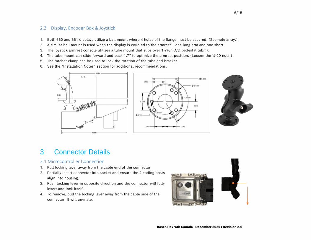
2.3 Display, Encoder Box & Joystick 1. Both 660 and 661 displays utilize a ball mount where 4 holes of the flange must be secured. (See hole array.)
2. A similar ball mount is used when the display is coupled to the armrest – one long arm and one short.
3. The joystick armrest console utilizes a tube mount that slips over 1-7/8” O/D pedestal tubing.
4. The tube mount can slide forward and back 1.7” to optimize the armrest position. (Loosen the ¼-20 nuts.)
5. The ratchet clamp can be used to lock the rotation of the tube and bracket.
6. See the “Installation Notes” section for additional recommendations.
3 Connector Details
3.1 Microcontroller Connection 1. Pull locking lever away from the cable end of the connector
2. Partially insert connector into socket and ensure the 2 coding posts
align into housing.
3. Push locking lever in opposite direction and the connector will fully
insert and lock itself. 4. To remove, pull the locking lever away from the cable side of the
connector. It will un-mate.

7/15
Bosch Rexroth Canada ı December 2020 ı Revision 2.0
3.2 Solenoid Connection
4 Cable Connections
4.1 CS660 Display
1 Connect the CANBUS EXTENSION from CAN connector on the display to the CAN1 connector on the junction
box.
2 Connect all sensor cables such as conveyor speed, ground speed from the sensors to the correct connector on
the junction box.
3 Connect all valve splitter cables from the junction box to the proper solenoids on the hydraulic valve assembly
2. Press metal retainer to un-mate 1. Press valve cable end onto solenoid connector

8/15
Bosch Rexroth Canada ı December 2020 ı Revision 2.0
4.2 CS661 Heads Up Display with Encoder Box
1 Connect from CAN connector on the display to one of the leads on the CAN splitter cable.
2 Connect the other lead of the CAN splitter cable to the CAN1 connector on the encoder box. The encoder box
may be attached to the joystick console. See OSD for details.
3 Connect the other end of the CAN splitter cable to CAN1 connector on the junction box
4 Connect all sensor cables including ground speed to the correct connector on the junction box.
5 Connect all valve splitter cables from the junction box to the proper solenoids on the hydraulic valve assembly
NOTE: INLINE SENSOR NETWORK(PN:R987376742) NEEDS TO BE INSTALLED FOR SENSORS REQUIRING A PULL UP RESISTOR , SUCH AS WHITE MOTOR TYPES.
5 Installation Notes 5.1 Step 1 Unpack all the supplied parts and check the packing list for completeness.
5.2 Step 2 Untie and layout all the cables supplied, to ensure proper lengths.
Note: Electromagnetic devices such as relays, magnetic switches and solenoids, can generate large negative voltage
spikes. These large spikes are introduced into the vehicle’s electrical system and may adversely affect all electronic
devices including engine computers. It is strongly recommended that these electromagnetic devices be electrically
suppressed. See warnings and instructions in Body Builder manuals.
1. Connect the junction box power and the ground wire using a dedicated circuit only. (Recommend to connect to
the ignition switch)
2. Ensure wiring for transmission devices such as radios, etc. are not attached to the controller or bundled with
the controller wiring. And a sufficiently large distance to radio systems must be maintained.
3. Make sure all mounting posts are properly grounded; a direct ground wire to the negative battery post is
recommended. Floor mats and undercoating will interfere with proper grounding.
4. Disconnect the battery terminals before welding on a vehicle with electronic equipment.
5. Disconnect the negative battery terminal when wiring electronic devices.
6. Mount the consoles so that they do not interfere with vehicle controls or obstruct visibility.
7. Mount microcontrollers so that oil and salt spray do not contact the housing.
8. Route cables so that they will not be abused, damaged or immersed in oil.
9. When routing cables through metal opening, always use grommets to prevent cable damage.

9/15
Bosch Rexroth Canada ı December 2020 ı Revision 2.0
10. When running wires around a dump box pivot point, ensure no connectors can be separated when the hoist is
activated.
11. Tie cables clear of all moving parts like drive-axles or conveyor chains.
12. Observe the cable labeling (under the clear cover) for the proper termination of inputs and outputs.
13. Use dielectric grease on all external cable connections and pins to ensure proper corrosion protection.
14. Thoroughly clean all power and ground terminals before connecting power harness.
15. Stand clear of any hydraulic functions when first powering up the system
16. DO NOT drill holes in any of the enclosures.
17. DO NOT re-wire any of the consoles or cable harnesses.
18. DO NOT weld on the vehicle without completely disconnecting all electronic consoles.
5.3 Fuses
Replace fuse with appropriate rating:
RC4-5 Junction Box 15A CS660 Console 2.5A RC28-14 Junction Box 30A CS550 Encoder Box 2.5A
Note: Failure to maintain proper fuse protection can lead to product damage and fire hazard not covered by warranty. And failure to follow the recommendations will void your warranty.
Loosen screws and remove connector Fuse
Push and turn to retrieve fuse
Push and turn to retrieve fuse

10/15
Bosch Rexroth Canada ı December 2020 ı Revision 2.0
6 Installation Test Checklist Work order #: Date:
Part number: Software Version:
Serial number: Signature:
After all controller cables and hydraulics are plumbed – vehicle hopper empty
OK NOTES
Start the vehicle – engage hydraulic pump
Power on display, check for backlight and display operation
Press and hold the “speed” field for 5 seconds , press “up arrow” to set a
speed– (Turning on simulated ground speed)
Press the up arrow again to increase speed to 20
Rotate all the dials clockwise to 5 – rate should change
Verify that the conveyor/auger is operating – feedback?
Verify that the spinner is operating
Verify that the liquid pump is operating – feedback?
Verify that the gate cylinder and sensor is operating
(if equipped)
Press the speed down arrow to lower the speed to 0 –
press the speed field to exit
Drive the vehicle to check that vehicle speed registers
Activate the joystick as defined in the OSD test drawing –
verify proper actuation
Test special functions – power float, low oil, emergency raise
Test auxiliary switches for proper operation
The above procedure is a simple way to verify system connections, hydraulics operation, and sensor
feedback. It may not work for all the systems. The reliable way to test is to follow the steps in CS-660
Calibration Manual.

11/15
Bosch Rexroth Canada ı December 2020 ı Revision 2.0
7 Example system layout
Attention: This diagram is an example only. Please refer to your order specific documentation.

12/15
Bosch Rexroth Canada ı December 2020 ı Revision 2.0
8 Example system layout with Joystick Console
Attention: This diagram is an example only. Please refer to your order specific documentation.

13/15
Bosch Rexroth Canada ı December 2020 ı Revision 2.0
9 Cable Connection Chart RC4-5 Controller RC4-5 Junction box
connectors Default function (Refer to order specific documentation) Spinner or conveyor reverse
Sensors
S1-A Ground Speed Ground Speed
S1-B Spare Spare
S2-B Spinner SS Spinner SS
S2-A Conveyor Speed Conveyor Speed
S3-B Anti-Ice flow /Level Anti-Ice flow /Level
S3-A Prewet flow/Level Prewet flow/Level
Analog Inputs
A1-A Configurable Configurable
A1-B Configurable Configurable
A2-A Gate Position Sensor Gate Position Sensor
A2-B Configurable Configurable
A3-A Configurable Configurable
A3-B Configurable Configurable
Dig Sensors-8pin
D1-8 Configurable Configurable
PWM Outputs
V1-B Conveyor output Conveyor output
V1-A Spinner output Conveyor reverse
V2-B Prewet Spinner output
V2-A Anti-Ice Spinner reverse
Digital Outputs
V3-B Configurable, GS12-default Prewet
V3-A Configurable, Reverse-default Anti-Ice
V4-B Gate Up Gate Up
V4-A Gate Down Gate Down
V5-B Configurable (Dig Option 3)
V5-A LEDop(50mA) LEDop(50mA)
Attention: This chart is an example only. Please refer to your order specific documentation (OSD).

14/15
Bosch Rexroth Canada ı December 2020 ı Revision 2.0
10 Cable Connection Chart with Joystick Console
RC28-14 Controller Junction box connectors
Junction box connectors Spinner or conveyor reverse
Sensors
S1-A Ground Speed Ground Speed
S1-B Spare Spare
S2-A Conveyor Speed Conveyor Speed
S2-B Spinner Speed Spinner Speed
S3-A Prewet flow/Level Prewet flow/Level
S3-B Anti-Ice flow/Level Anti-Ice flow/Level
Analog Inputs
A2-A Gate Position Gate Position
A2-B Configurable Configurable
A1-B Configurable Configurable
A1-A Configurable Configurable
A3-A Configurable Configurable
A3-B Configurable Configurable
Digital Inputs
D1-8 Configurable Material detect
Prox Inputs
P1-A Prox1 Prox1
P1-B Prox2 Prox2
PWM Outputs
V1-B Conveyor output Conveyor output
V1-A Spinner output Conveyor reverse
V2-B Prewet Spinner output
V2-A Anti-Ice Spinner reverse
V3-B Configurable, GS12-default Prewet output
V3-A Configurable, Reverse-default Anti-Ice
V4-B Gate Up Gate Up
V4-A Gate Down Gate Down
V5-B C-Boom(Dig Option 2) (Dig Option 2)
V5-A R-Boom(Dig Option 3) (Dig Option 3)
Joystick Function Outputs
J1 1A,1B 1A,1B
Attention: This chart is an example only. Please refer to your order specific documentation.
15/15
Bosch Rexroth Canada ı December 2020 ı Revision 2.0
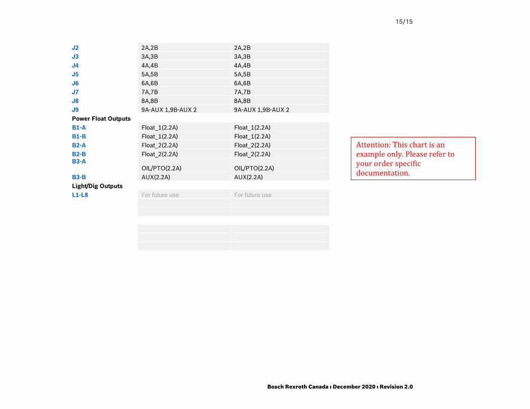
J2 2A,2B 2A,2B
J3 3A,3B 3A,3B
J4 4A,4B 4A,4B
J5 5A,5B 5A,5B
J6 6A,6B 6A,6B
J7 7A,7B 7A,7B
J8 8A,8B 8A,8B
J9 9A-AUX 1,9B-AUX 2 9A-AUX 1,9B-AUX 2
Power Float Outputs
B1-A Float_1(2.2A) Float_1(2.2A)
B1-B Float_1(2.2A) Float_1(2.2A)
B2-A Float_2(2.2A) Float_2(2.2A)
B2-B Float_2(2.2A) Float_2(2.2A)
B3-A OIL/PTO(2.2A) OIL/PTO(2.2A)
B3-B AUX(2.2A) AUX(2.2A)
Light/Dig Outputs
L1-L8 For future use For future use
Attention: This chart is an example only. Please refer to your order specific documentation.