CS348: Computer Networks Network Layer Introduction
29
CS348: Computer Networks Dr. Manas Khatua Assistant Professor Dept. of CSE, IIT Guwahati E-mail: [email protected] Network Layer Introduction
Transcript of CS348: Computer Networks Network Layer Introduction

CS348: Computer Networks
Dr. Manas KhatuaAssistant Professor
Dept. of CSE, IIT GuwahatiE-mail: [email protected]
Network Layer Introduction

Introduction
11-05-2020 2Dr. Manas Khatua
Network Layer is responsible for host-to-host delivery of packets.

Network Service Models• It defines the characteristics of end-to-end transport of packets
• Few services that can be provided by Network Layer– Guaranteed delivery– Guaranteed delivery with bounded delay
– In-order packet delivery– Guaranteed minimum bandwidth– Guaranteed maximum jitter– Security Service– Congestion Indication
11-05-2020 3Dr. Manas Khatua
• eventual delivery of transmitted packets are not guaranteed
• timing between packets is not guaranteed to be preserved
• packets are not guaranteed to be received in order

Forwarding and Routing• Forwarding involves the transfer
of a packet from an incoming link to an outgoing link within a single router
• It is the router-local action of transferring a packet
• Routing involves all of a network’s routers, whose collective interactions via routing protocols determine the paths that packets take on their trips from source to destination node.
• It is the network-wide process that determines the end-to-end paths
• Routing algorithms determine values in forwarding tables
• Routing algorithm may be centralized or distributed
11-05-2020 4Dr. Manas Khatua
Every router has forwarding table

Connection(less) Service• Transport layer can offer connectionless service or connection-oriented service
between two processes.
• Network layer can provide connectionless service or connection service between two hosts.
• Network-layer services in many ways parallel transport-layer services. But, there exist crucial differences:
11-05-2020 5Dr. Manas Khatua
In Network Layer In Transport Layer
Provide host-to-host service Provide process-to-process services
Can’t provide both together- Virtual-circuit network (e.g. ATM, Frame Relay)- Datagram network (e.g. Internet)
Can provide both connection together
Implemented in the routers as well as in the end systems
Implemented at the edge of the network or in the end systems

Virtual-Circuit Network
11-05-2020 6Dr. Manas Khatua
12 22 32VC#• Network layer connections are
called virtual circuits (VCs).
• A VC consists of – (1) a path (i.e., a series of links
and routers) between the source and destination hosts
– (2) VC numbers, one number for each link along the path,
– (3) entries in the forwarding table in each router along the path.
• A virtual circuit may have a different VC number on each link
• A packet belonging to a virtual circuit will carry a VC number in its header.
Forwarding Table for R1

Cont…
11-05-2020 7Dr. Manas Khatua
• Three identifiable phases in a virtual circuit– VC setup– Data transfer– VC teardown
• VC setup at the network layer v/s connection setup at the transport layer– During transport-layer connection setup, the two end
systems alone determine the parameters of their transport-layer connection.
– With a VC network layer, routers along the path between the two end systems are involved in VC setup, and each router is fully aware of all the VCs passing through it.

Datagram Network
11-05-2020 8Dr. Manas Khatua
• each time an end system wants to send a packet, it stamps the packet with the address of the destination end system
• the router matches a prefix of the packet’s destination address with the entries in the table
• When there are multiple matches, the router uses the longest prefix matching rule
A forwarding table of router R1
Cont…
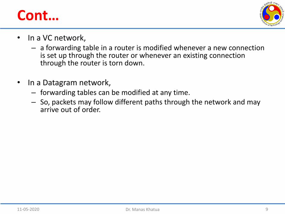
• In a VC network, – a forwarding table in a router is modified whenever a new connection
is set up through the router or whenever an existing connection through the router is torn down.
• In a Datagram network,– forwarding tables can be modified at any time.– So, packets may follow different paths through the network and may
arrive out of order.
11-05-2020 9Dr. Manas Khatua

Router Architecture
• SDN: Software Defined Networking– Decouples the Data plane and Control plane
11-05-2020 Dr. Manas Khatua 10
High-level view of a generic router architecture• Input Ports• Switching fabric• Output Ports• Routing processor
Physical layer function
Link-layer function
Lookup function

Cont…
• Buffer Management
– Drop-tail queuing (i.e. drop the arriving packets from tail)
– Selective drop (i.e. drop one already queued packet using some scheduling policy)
– Active Queue Management (i.e. drop/mark a packet before the buffer is full. e.g., Random Early Detection (RED) )
11-05-2020 Dr. Manas Khatua 11
Cont…
11-05-2020 Dr. Manas Khatua 12
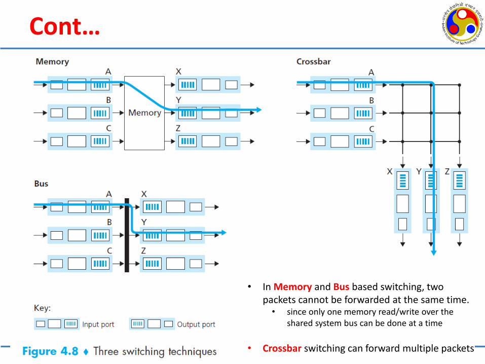
• In Memory and Bus based switching, two packets cannot be forwarded at the same time.• since only one memory read/write over the
shared system bus can be done at a time
• Crossbar switching can forward multiple packets

Where Does Queueing Occur?
11-05-2020 Dr. Manas Khatua 13
HOL blocking at an input port queued switch
Output port queuing

IP Addressing
11-05-2020 14Dr. Manas Khatua
• IP Address: – 32 bits used to represent IPv4– E.g., 192.19.241.18 in dotted decimal notation
• Total address space: 2n for n bit address– Last address: 255.255.255.255 if n=32
• An IP address is technically associated with an interface, rather than with the host or router containing that interface
• The boundary between the host/router and the physical link is called an interface.
• Each interface in the global Internet must have an IP address that is globally unique (except behind NAT)

Classful Addressing
11-05-2020 15Dr. Manas Khatua

Problem and Solution
11-05-2020 Dr. Manas Khatua 16
• Problem in Classful Addressing: Address Depletion
• Solution: – Subnetting: a larger block of address is divided into several subnets– Supernetting: several smaller blocks of addresses are combined to
make a larger block
• Better Solution: – Classless addressing: variable length blocks that belong to no classes;
uses slash notation to identify prefix length

Example of Six Subnets
11-05-2020 Dr. Manas Khatua 17
223.1.1.x
223.1.3.x223.1.2.x
223.1.9.x 223.1.7.x
223.1.8.x
223.1.x.x

Extract block from an Address
Let an address: 167.199.170.82/27 . . .01010010
Number of Address: 2(32-27) = 32First Address: 167.199.170.64/27 . . .01000000Last Address: 167.199.170.95/27 . . .01011111
11-05-2020 Dr. Manas Khatua 18

Address Mask
11-05-2020 Dr. Manas Khatua 19
It is a 32-bit number in which the n leftmost bits are set to 1s and the rest of the bits (32 - n) are set to 0s.
It can be used by a computer program to extract the information in a block, using the three bit-wise operations NOT, AND, and OR.
Given address: 167.199.170.82/27 . . .01010010Mask: 255.255.255.224 . . .11100000
Number of address in the block: NOT (mask) + 1 = 31+1 = 32
First Address: (address) AND (mask) 167.199.170.64 (01000000)Last Address: (address) OR (NOT (mask) ) 167.199.170.95 (01011111)

Network Address
• Network address is the first address of the block
11-05-2020 Dr. Manas Khatua 20

Block Allocation• Internet Corporation for Assigned Names and Numbers (ICANN) is the global authority.
• ICANN assigns a large block of address to ISP
• ISP assigns individual IP to stations/ small block to an organization
• Rules:1. The number of requested addresses, N, needs to be a power of 2. (as, N=232-n => n = 32 – log2 N)
2. The allocated first address needs to be divisible by the number of addresses in the block. (for contiguous address)
11-05-2020 Dr. Manas Khatua 21
• More levels of hierarchy can be created using subnetting.• Rules:
1. The number of addresses (N) in each subnetwork should be a power of 2; i.e., N = 2k
2. The prefix length (in bits) for each subnetwork should be found using the following formula: nsubnet = 32 – log2 N
3. The starting address in each subnetwork should be divisible by the number of addresses in that subnetwork. (i.e., least significant k bits should all be 0)

Example• An organization is granted a block of addresses with the beginning address
14.24.74.0/24. • The organization needs to have 3 sub-blocks of addresses to use in its three subnets:
one sub-block of 10 addresses, one sub-block of 60 addresses, and one sub-block of 120 addresses. Design the sub-blocks.
• Solution: Allocated no. of address: 232-24 = 256First address: 14.24.74.0/24; Last address: 14.24.74.255/24Mask: 255.255.255.0
We should start with largest sub-blocks. N1=120 => N1=128 => n1=32-log2128 = 25
First address: 14.24.74.0/25Last address: 14.24.74.127/25 Mask: 255.255.255.128 (as last octet: 1000 0000)
N2=60 => N2=64 => n2=32-log264 = 26First address: 14.24.74.128/26Last address: 14.24.74.191/26 Mask: 255.255.255.192 (as last octet: 1100 0000)
N3=10 => N3=16 => n3=32-log216 = 28First address: 14.24.74.192/28Last address: 14.24.74.207/28 Mask: 255.255.255.240 (as last octet: 1111 0000)
11-05-2020 Dr. Manas Khatua 22

Cont…
• Example: Let destination IP of a packet 14.24.74.195So, Network Address= (14.24.74.195) AND (255.255.255.0) = 14.24.74.0
• Subnet 3: (14.24.74.195) AND (255.255.255.240) = . . . (1100 0011 AND 1111 0000) = 14.24.74.192 => Correct
• Subnet 2: (14.24.74.195) AND (255.255.255.192) = . . . (1100 0011 AND 1100 0000) = 14.24.74.192 => Not Correct
• Subnet 1: (14.24.74.195) AND (255.255.255.128) = . . . (1100 0011 AND 1000 0000) = 14.24.74.128 => Not correct
11-05-2020 Dr. Manas Khatua 23
14.24.74.192/28

Address Aggregation
11-05-2020 Dr. Manas Khatua 24

Special Addresses
• This-host Address: 0.0.0.0/32– It is used whenever a host needs to send an IP datagram but it does not know its own address
to use as the source address.
• Limited-broadcast Address: 255.255.255.255/32– It is used whenever a router or a host needs to send a datagram to all devices in a network.
• Loopback Address: 127.0.0.0/8– Any address in the block is used to test a piece of software in the machine.
• Private Addresses: (these are used in NAT)– 10.0.0.0/8– 172.16.0.0/12– 192.168.0.0/16– 169.254.0.0/16
• Multicast Addresses: 224.0.0.0/4– Reserved for multicast
11-05-2020 Dr. Manas Khatua 25

IP Packet Forwarding
• Two Approaches:– Based on Destination IP
• For connectionless protocol
– Based on Label• For connection oriented protocol
11-05-2020 Dr. Manas Khatua 26

Forwarding (by Dest. IP)
11-05-2020 Dr. Manas Khatua 27
Table for Router R1
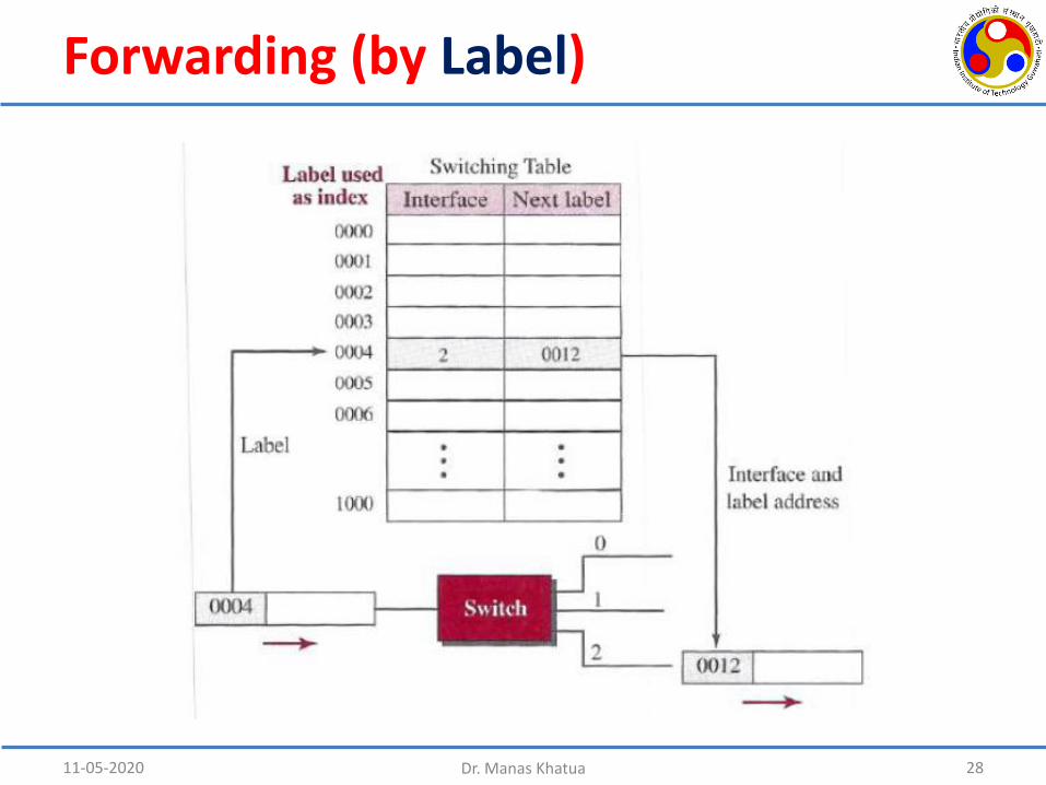
Forwarding (by Label)
11-05-2020 28Dr. Manas Khatua

11-05-2020 29Dr. Manas Khatua