CS-LNF 31 May 2006 Agenda: Second generation at DAFNE. Precision physics Nuclear physics Particle...
32
CS-LNF 31 May 2006 • Agenda: • Second generation at DAFNE. Precision physics • Nuclear physics • Particle physics • “High energy” physics • Is it worth doing it?...How and when…?
-
Upload
howard-cole -
Category
Documents
-
view
215 -
download
1
Transcript of CS-LNF 31 May 2006 Agenda: Second generation at DAFNE. Precision physics Nuclear physics Particle...

CS-LNF 31 May 2006• Agenda:
• Second generation at DAFNE. Precision physics
• Nuclear physics• Particle physics• “High energy” physics
• Is it worth doing it?...How and when…?

2006 2007 2008 2009 2010
FINUDA FINUDA ?-KLOE2?SIDDHARTA
FEL – SPARC
HILL – FLAME Accelerazione Laser
CNAO
SPARCX- TORVERGATA
LNF-INFN horizon
Synchrotron light at DAFNE
LINAC BTF
KLOE
CTF3- Comb.Ring AND RUNNING AT CERN
DAFNE UPGRADES
ILC LHC RF-X
TESLA
DAFNE RUNNING AND MAINTENANCE
SPARX-ino?

To have a second generation experiment at LNF ……………..we have to say it now……………

COLLIDERS
FACTORIES
SUPERFACTORIES
Linear colliders

DAfne New Adjustable Energy : letter of intents
49 Authors
FrascatiNovosibirskBrookhaven
SLACJapan?
50ft-1 in 5 years
1-2.4 GeV total energy
8-10 *1032 cm-2 s-1(11 ft-1/ anno)

DANAEDANAEEnergy and Luminosity RangeEnergy and Luminosity Range
Energy @center of mass (GeV) 1.02 2.4
Integrated Luminosity per year (ftbarn-1) > 10 1
Total integrated luminosity > 50 3
Peak luminosity > (cm-2sec-1) 1033 1032

LETTER OF INTENTS AUTHORS INSTITUTES IST-ESTERI1) AMADEUS 111 30 242) DANAE-L 7 LNF3) DANTE 72 22 114) KLOE-2 70 12 7

Use of DANE buildingsUse of DANE infrastructuresUse of DANE injection system + upgrade of transfer linesUse of large part of magnets, diagnostics
New • Dipoles• Wigglers• Rf system• Vacuum chamber• Interaction region
Application of new technologies Use of all expertise and experience of DANEUse of DANE runs for R&D while increasing L for next experiments

DANAE layout
SC wigglers
Sc rf
INJECTION
IROnly one IR
Continuous injection……..

Table II – DANAE design parameters as a -factory, and at the maximum energy, compared with DANE parameters at the present peak luminosity.
Units DANEDANAE
@ DANAE1.2 GeV
Energy (center of mass) Ecm GeV 1.02 1.02 2.4
Energy per ring E GeV 0.51 0.51 1.2
Circumference C m 97.69 96.34 96.34
Revolution frequency Frev MHz 3.07 3.11 3.11
Time between collisions Tc nsec 2.7 2 6
Bunch spacing sb m 0.81 0.60 1.80
Half crossing angle /2 mrad 15 15 15
# of Colliding Bunches Nb 110 150 30
More bunches…….

Particles per bunch Npart (1010) 2-3 3 3.4
Beam current (e-/e+) I A 1.4/1.3 2.25 0.5
Bunch current (e-/e+) Ib mA 13/12 15 16.6
Peak Luminosity (1032) Lpeak cm-2sec-1 1.5 10 > 2
Specific Luminosity/bunch (1028)
Lsp cm-2sec-1mA-2 0.9 3 3
H function @ IP H m 2 1 1
V function @ IP V cm 1.8 0.8 1
Horizontal emittance m rad 0.4 0.45 0.45
Coupling factor 1.1 0.5 0.5
H in collision x mm 1.26 0.95 0.95
V in collision y m 12.6 6 6.7
Beam-beam tune shift x 0.026 0.030 0.014
y 0.025 0.038 0.020
Bunch length (e-/e+) L cm 3/2 1 1.5
Piwinski angle rad 0.42 0.22 .33
Momentum compaction c 0.027 0.02 0.03
More specific luminosity……….more current…
Units DANEDANAE
@ DANAE1.2 GeV

* *4coll
x y
f N NL
N+N-
Increasing of cross section with current due - Beam-beam- Single beam effects (Single bunch effects + Total current effects)Stronger for lower energy
Increasing the luminosity by:Increasing the slope (smaller cross section)Increasing the current Fighting the blowup effects
Higher luminosities
DANE highest L

DANAE LATTICE

Energy spread – bunch length – rf system
2 22 3
2 42qE
q
CIC
E I I
2c cE EL
s o
c Ec
E heV E
More radiation :larger energy spread – longer bunch
Bunch length can be shortenedby increasing h, V
Natural bunch length and energy spread at low current are definedby the magnetic lattice, the momentum compaction and the rf system

Short bunch length at high current:• Low impedance• High voltage
1
1,5
2
2,5
3
3,5
0 10 20 30 40 50
Measurements 2000Simulation 1998Measurements 2004
I [mA]
FWHM/2.3548 [cm]
2/
2/
c E lth
E e EI
Z n R
Above the microwave instability current thresholdL increases with the current, not depending on c
SIMULATIONS and MEASUREMENTS ON DANE
6
7
8
9
10
11
12
0 5 10 15 20 25 30
I [mA]
SigmaZ [mm]
alfa = +0.02
alfa = -0.02
alfa = -0.03
SIMULATIONS for DANAE

DANAE lattice and dynamic aperture

IT IS EASIER
Increasing the luminosity by:Increasing the slope (smaller cross section)Fighting the blowup effects
BUTPower = Current x Energy loss
Higher energies Higher Magnetic fields
P (a.u.)
N+N- or L (a.u.)
E = 0.51 GeV
E = 1.2 GeV
Limit in power =Limit in current
4 22 2,o dip wigU I E I E

12 DIPOLES per ring normal conducting
Maximum field: 1.72 T
Gap = 4.3 cm
I2 = 2.7 m-1
1.72 T Dipole Magnet, POISSON simulation

SC Wigglers to further increase radiation
Lw = 6 m @ B = 4 Tx (@510 MeV) = 13 msec I2 = 22 m-1 x (@1.2 GeV) = 5 msec I2 = 6 m-1
2
2
1
2 w
Bi L
B
Energy 0.51 1.2
Maximum magnetic field Bmax T 4 4
Total number of poles 19 19
Total length m 2.96 2.96
Central pole length cm 16 16
End poles length cm 8 8
2nd and penultimate poles length cm 12 12
End poles field ratio with Bmax 0.5 0.5
2nd and penultimate field ratio with Bmax 1 1
Max trajectory oscillation mm 6 2.5
Path – wiggler length difference mm 11.8 2.1
Total vertical beam stay clear cm 2 2
Total horizontal beam stay clear cm 8.5 8.5
E = 0.51 GeV E = 1.2 GeV
DANAE wiggler parameters

By (s)
By (x)
By/By = 5 10-4 @ 2 cm
SC Wiggler built at BINPBmax = 7 Tfor SIBERIAII
Collaboration with BINP group:

RF system Harmonic number : 160Maximum # bunches: 150
-Energy High Energy
fRF 500 MHz
VRF 0.5 MV 1.5 MV
type SC, KEKB-like
R/Q 46 Ω
Q0 2 ∙ 109 @ 4.2 K
Rs 92 GΩ
PRF 1.5 W 12.5 W
PStatic 40 W
Ib 2.25 A 0.5 A
U rad 21.4 keV 165 keV
PBeam 48 kW 82.5 kW
100 kW CW, IOT or Klystron
Qext 32 ∙ 103 6.6 ∙ 103

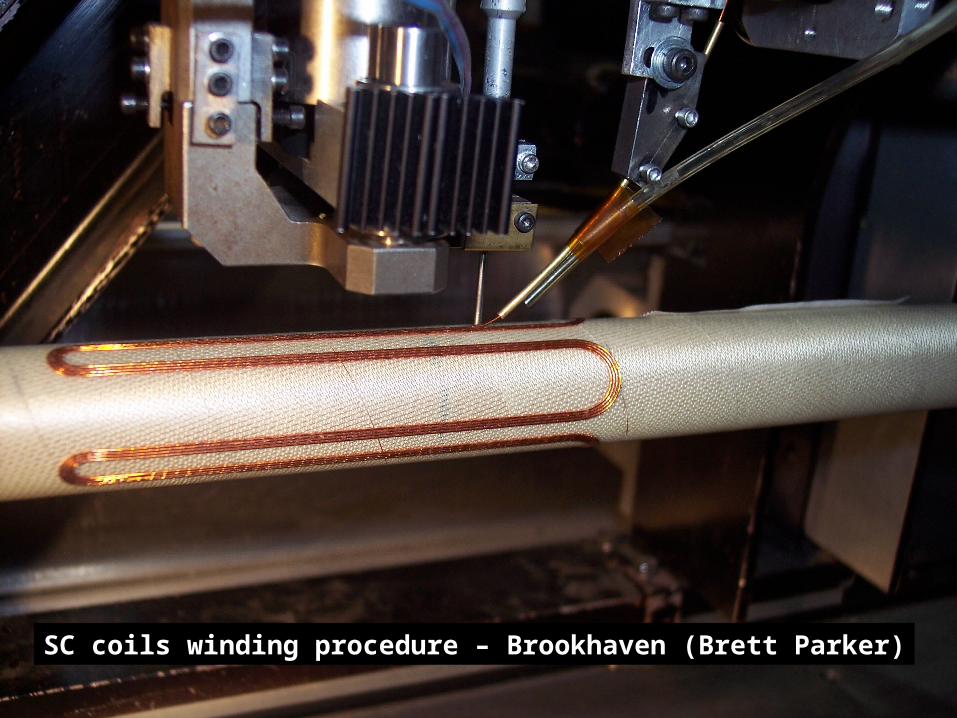
DANAE Interaction Region – tunable with energy and Bsol
Compatible with KLOE detectorSC low beta quads + skews + antisolenoids
SC coils winding procedure – Brookhaven (Brett Parker)
Transverse view
DANAE QD DANAE Antisolenoid
2D Longitudinal view
B. Parker design

VACUUM CHAMBERS
Keep more regular vacuum chamber shape (experience from DANE and CTF3)Use of small ICE wih negligible impedanceTi coating for e+ surfacesOptimisation of slots and bellows for 1 cm bunch lengths
Negligible contribution to impedance of short ICEs
CTF3 vacuum chambers

Longitudinal Feedback kicker
Parameters of PEPII kicker, designed by LNF, almost equal to DANAE ones.

Injection system
•Linac + Accumulatore OK •Doubling transfer lines for optimizing <L>•New kickers (R&D on DANE in progress)•Ramping for high energy option
The High Luminosity option needs
continuous injection
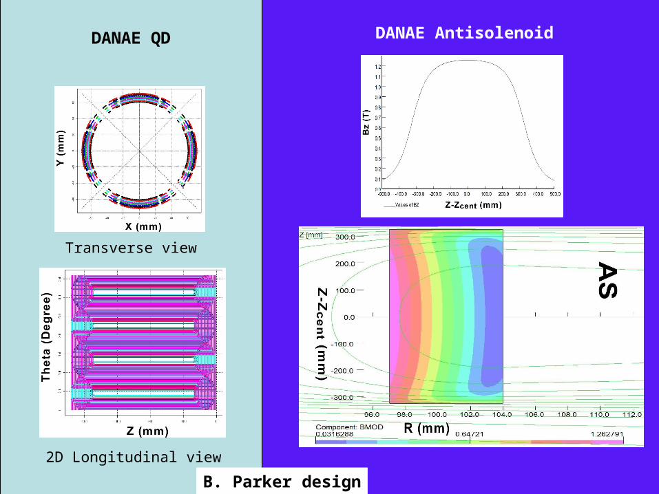
Tentative schedule
• To CDR and Project approval (2006)• To + 1 year call for tender• To + 2 years construction and delivery• To + 3 years DANE decommissioning and
DANAE installation • To + 4 years 1st beam for commissioning and for 1st experiment (2010)

Boosting DANAE basic performances
• Crab cavity
• Twisted crab
• Strong rf focusing
• ………
• ……… Very intense R&D on DAFNE is possible
….make a choise….the right one………….. and do it quickly….....

Questions to answer:
1) Is it the physics (particle and nuclear) worth doing?2) Should we include the high energy option?3) Which machine R&D’s have priority?4) How to proceed?
1) Which detector upgrades are necessary?2) Does it exists a collaboration willing to do it?
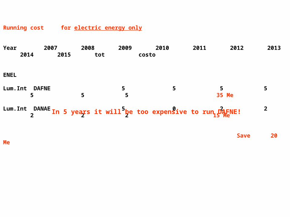
Running cost for electric energy only
Year 2007 2008 2009 2010 2011 2012 2013 2014 2015 tot costo ENEL
Lum.Int DAFNE 5 5 5 5 5 5 5 35 Me
Lum.Int DANAE 5 0 2 2 2 2 2 15 Me Save 20 Me
In 5 years it will be too expensive to run DAFNE!

Basic DANAE Parameters N-N
Energy per beam E GeV 0.51 1.2
Circumference C m 100 100
Luminosity L cm-2 sec-1 1033 1032
Current per beam I A 2.5 0.5
N of bunches Nb 150 30
Particles per bunch N 1010 3.1 3.4
Emittance mm mrad 0.45 0.45
Horizontal beta* x m 1 1
Vertical beta* y cm 0.8 1
Bunch length L cm 1 1.5
Coupling % 0.5 0.5
Energy lost per turn Uo (keV) 21 165
L damping time x (msec) 7.6 2.2
Beam Power Pw (kW) 48 (42w + 6d) 83 (43w + 40d)
Power per meter Pw/m (kW/m) 7w + 0.4d 7.2w + 2.7d