CS 7810 Lecture 15 A Case for Thermal-Aware Floorplanning at the Microarchitectural Level K....
14
CS 7810 Lecture 15 A Case for Thermal-Aware Floorplanning at the Microarchitectural Level . Sankaranarayanan, S. Velusamy, M. Stan, K. Skadr Journal of ILP, October 2005
-
date post
22-Dec-2015 -
Category
Documents
-
view
217 -
download
1
Transcript of CS 7810 Lecture 15 A Case for Thermal-Aware Floorplanning at the Microarchitectural Level K....

CS 7810 Lecture 15
A Case for Thermal-Aware Floorplanningat the Microarchitectural Level
K. Sankaranarayanan, S. Velusamy, M. Stan, K. SkadronJournal of ILP, October 2005

Importance of Temperature
• High power density cooling tech must improve
Every additional watt increases chip’s cooling/packaging cost by $4
• Higher temperature exponentially higher leakage
• Temperature variations cause wear and tear

General Approaches
• Reduce overall power consumption
• Wait for some unit to reach temperature limit and then throttle back (dynamic thermal management)
• Better floorplans so that heat is evenly distributed and likelihood of local hotspot is reduced
Better floorplanning does not eliminate the need for DTM

Thermal Modeling
• Thermal resistance: models the rate at which heat passes through• Thermal capacity: models the temperature rise because of heat absorption
Resistance thickness / area
Capacitance thickness x area
Models for Alpha-like Processor

Effect of Lateral Spreading
Thermal resistance = 0 Thermal resistance = infinity

Simulation Setup
• Ambient temperature of 40o C
• Trigger threshold (when DTM is invoked) 111.8o C
• Emergency threshold is 115o C
• Alpha core is 6.2mm x 6.2mm – cross-core latency is 4.21 and 7.16 cyc (on different metal layers)
• L2 cache is wrapped around the core to form a square
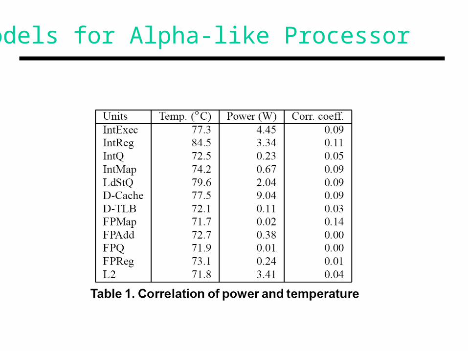
Simulated Annealing
• In each iteration, perturb the solution with a probability that equals the difference between the “quality” of current and optimal solution
• What is the metric for “quality”? ( A + W ) T
W = cij dij
A is area – some layouts increase the amount of white spaceW is the performance penalty becoz of wire delaysT is peak temperature for the layoutd is the distance between units in cycc reflects the performance impact of that distance

Inputs to Algorithm
• Profile a subset of benchmarks to estimate power density of each block
• Profile the performance impact of each set of wire delays to determine weights

Wire Delay Penalties
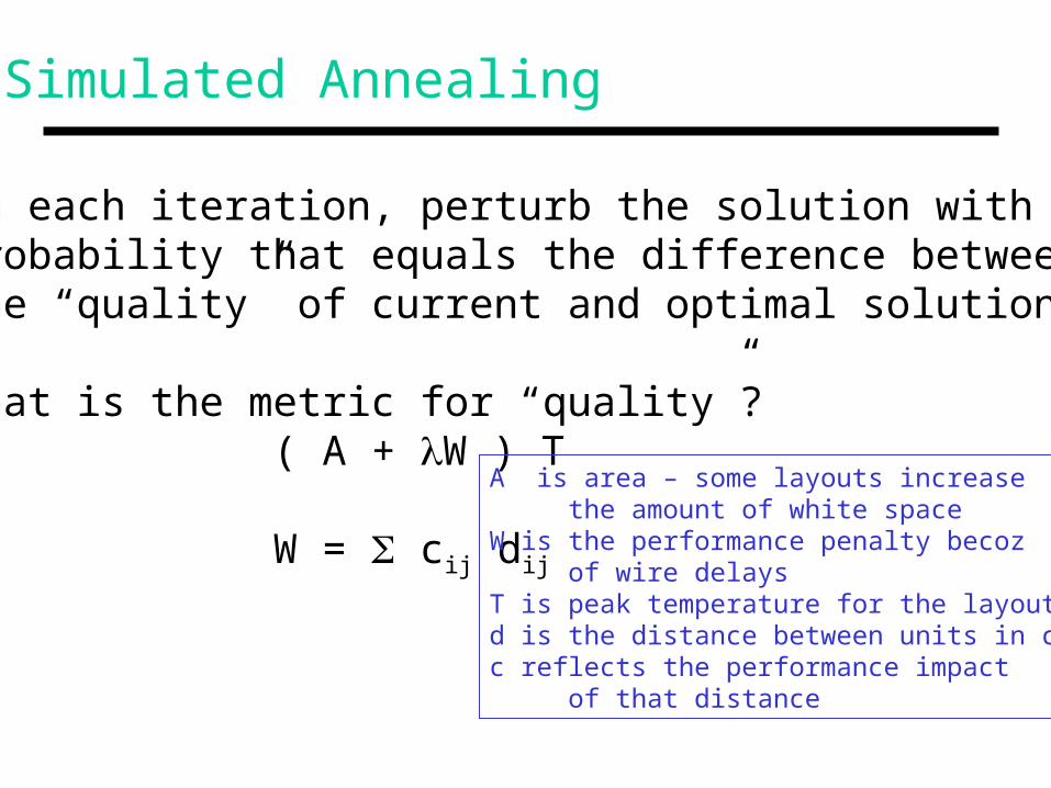
Optimal Floorplans
Flp-basic each wire delay gets an equal weight
Flp-advanced wire delays are weighted
Dead space1.14% 5.24%
Total wire length is longer here

Impact on Peak Temperature
Additional temp.reduction becoz
of poorer IPC andlower leakage
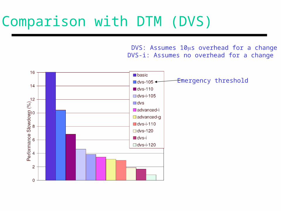
Comparison with DTM (DVS)
DVS: Assumes 10s overhead for a changeDVS-i: Assumes no overhead for a change
Emergency threshold

Title
• Bullet