CS 551 - Architecture. Systems Architecture CS 551 Lecture 5 P E R F O R M A N C E ERROR RECOVERY O...
65
CS 551 - Architecture
-
date post
22-Dec-2015 -
Category
Documents
-
view
216 -
download
2
Transcript of CS 551 - Architecture. Systems Architecture CS 551 Lecture 5 P E R F O R M A N C E ERROR RECOVERY O...

CS 551 - Architecture
Systems Architecture
CS 551 Lecture 5
PERFORMANCE
ERROR RECOVERY
OA&M
REQUIRE MENTS
REQUIRE MENTS
PROBLEM
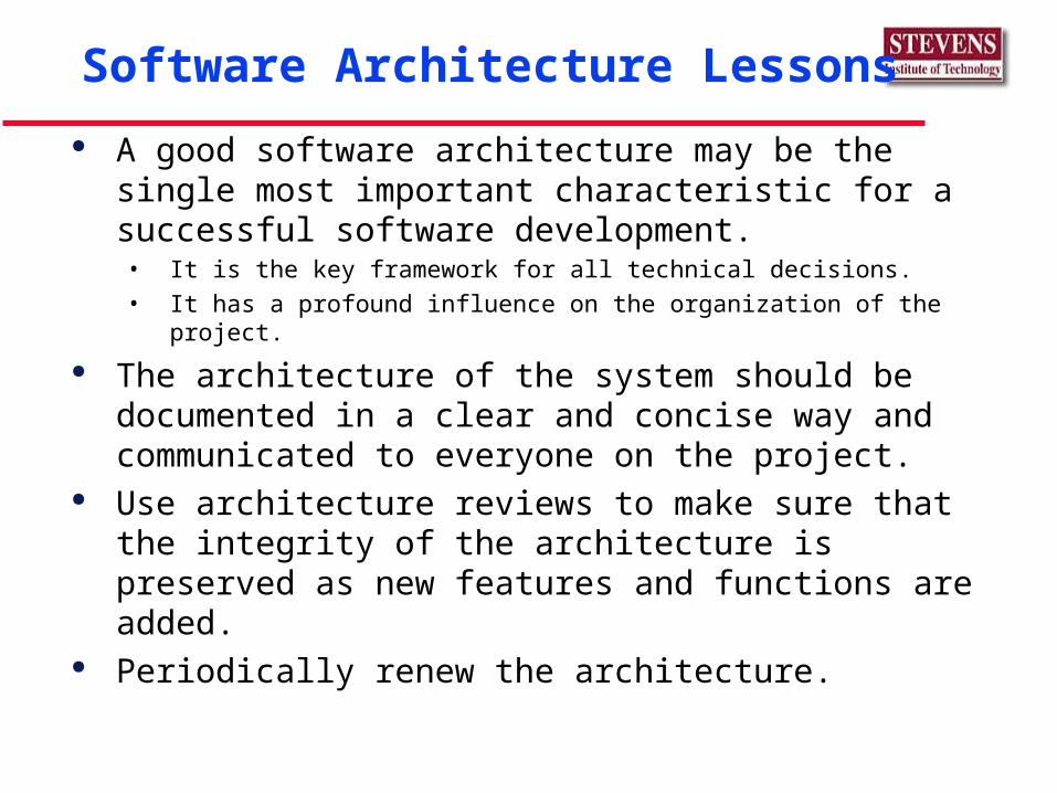
Software Architecture Lessons
A good software architecture may be the single most important characteristic for a successful software development.• It is the key framework for all technical decisions.
• It has a profound influence on the organization of the project.
The architecture of the system should be documented in a clear and concise way and communicated to everyone on the project.
Use architecture reviews to make sure that the integrity of the architecture is preserved as new features and functions are added.
Periodically renew the architecture.
The framework for all technical decisions.• A coherent, justified collection of design decisions.
• Technology and platform selection to match the problem.
A vehicle for communication among stakeholders.• A balance between features, cost and schedule.
A reusable and transferable abstraction of a system. • The basis for a product line or product family.
A mechanism to insure that the system meets the reliability, capacity, response time and throughput requirements.
Simplest satisfactory solution.
What is Software Architecture?
Benefits of Good Software Architectures
Helps identify and isolate reusable components that can speed implementation and improve system quality.
Assists in measuring project impacts of inevitable ongoing technical and business decisions and compromises.
Leads to clearly defined organizations with inherent project efficiencies, good communications and decision making.
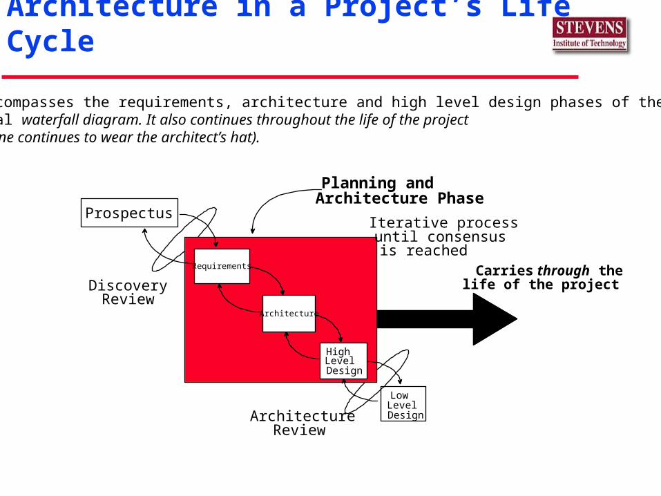
Architecture in a Project’s Life Cycle
Discovery
Planning and
ArchitectureReview
Review
Carries through thelife of the project
Iterative processuntil consensusis reached
Architecture PhaseProspectus
Requirements
Architecture
HighLevelDesign
LowLevelDesign
It encompasses the requirements, architecture and high level design phases of thetypical waterfall diagram. It also continues throughout the life of the project(someone continues to wear the architect’s hat).
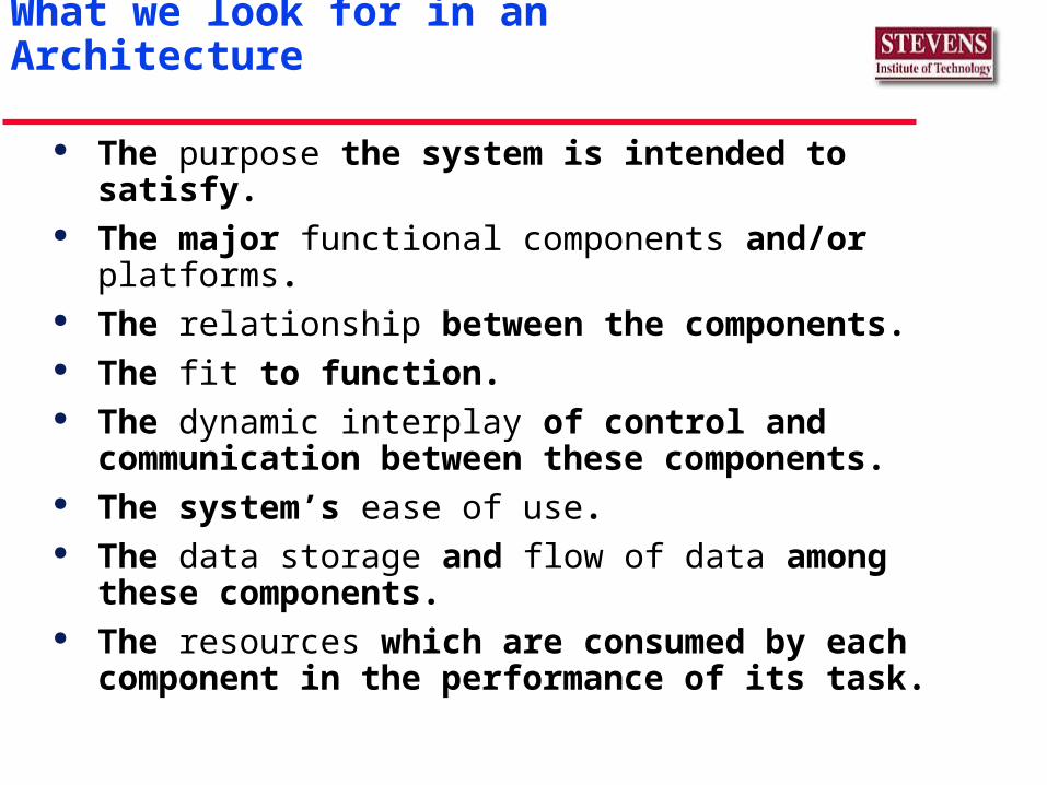
The purpose the system is intended to satisfy. The major functional components and/or platforms. The relationship between the components. The fit to function. The dynamic interplay of control and
communication between these components. The system’s ease of use. The data storage and flow of data among these
components. The resources which are consumed by each
component in the performance of its task.
What we look for in an Architecture
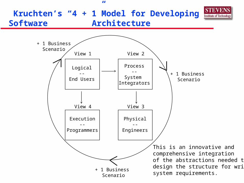
Kruchten’s “4 + 1”Model for Developing Software Architecture
+ 1 Business Scenario
+ 1 BusinessScenario
+ 1 Business Scenario
View 1
Logical--
End Users
View 2
Process--
System Integrators
View 3
Physical--
Engineers
View 4
Execution--
Programmers
This is an innovative andcomprehensive integrationof the abstractions needed to design the structure for writingsystem requirements.
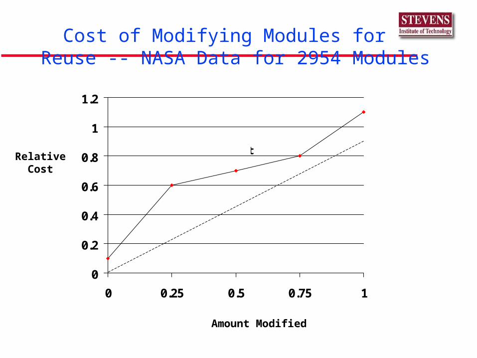
Cost of Modifying Modules for Reuse -- NASA Data for 2954 Modules
0
0.2
0.4
0.6
0.8
1
1.2
0 0.25 0.5 0.75 1
Usual LinearAssumption
Real Cost
Amount Modified
RelativeCost
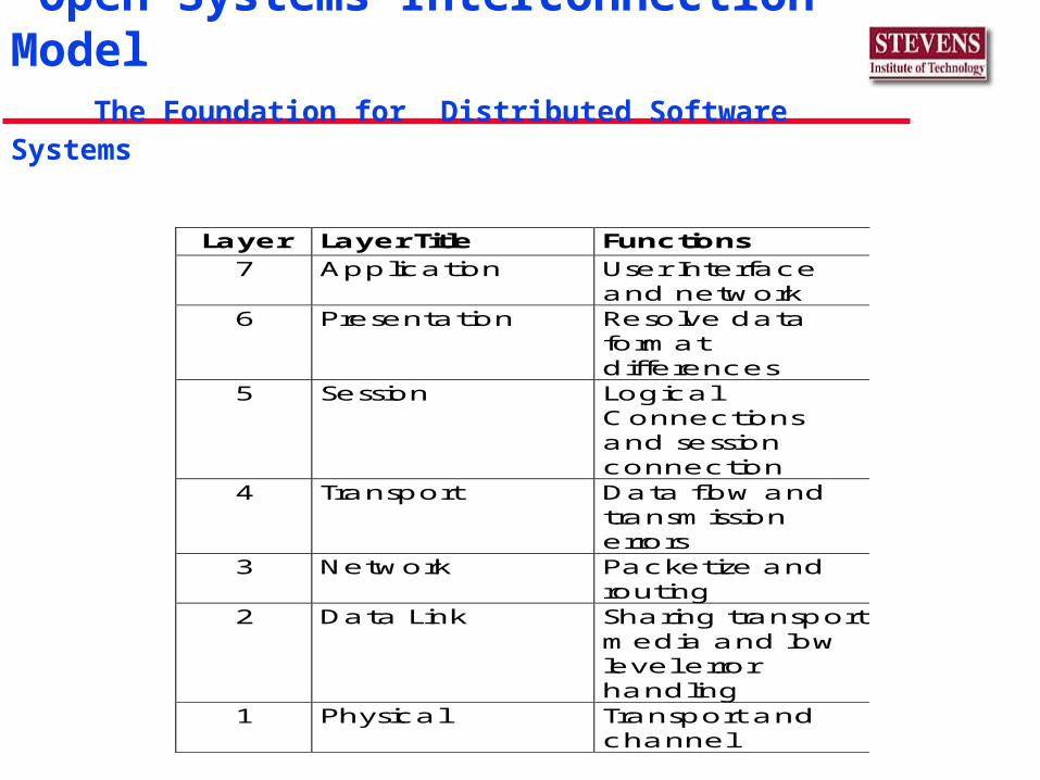
Open Systems Interconnection Model The Foundation for Distributed Software Systems
Layer Layer Title Functions 7 Application User Interface
and network 6 Presentation Resolve data
format differences
5 Session Logical Connections and session connection
4 Transport Data flow and transmission errors
3 Network Packetize and routing
2 Data Link Sharing transport media and low level error handling
1 Physical Transport and channel
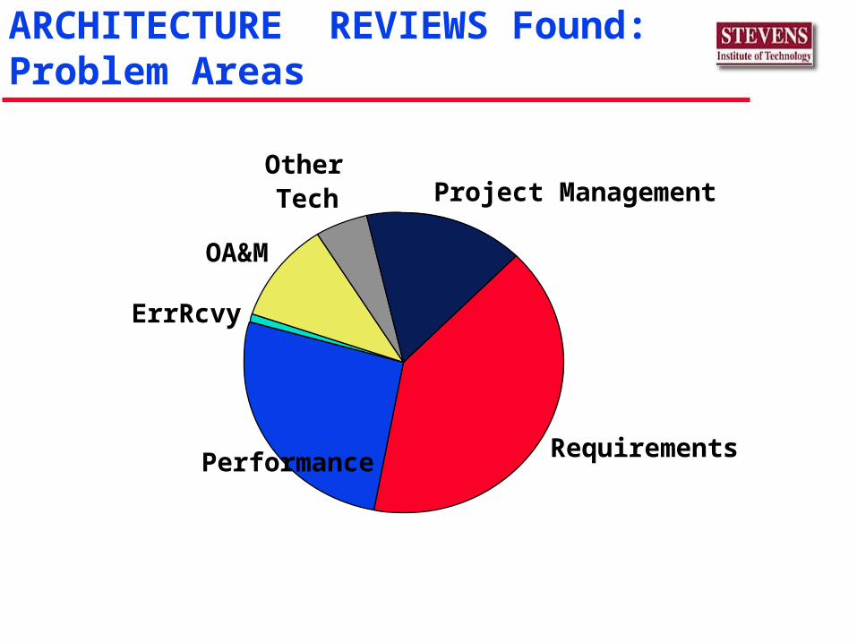
ARCHITECTURE REVIEWS Found:Problem Areas
RequirementsPerformance
ErrRcvy
Other Tech Project Management
OA&M
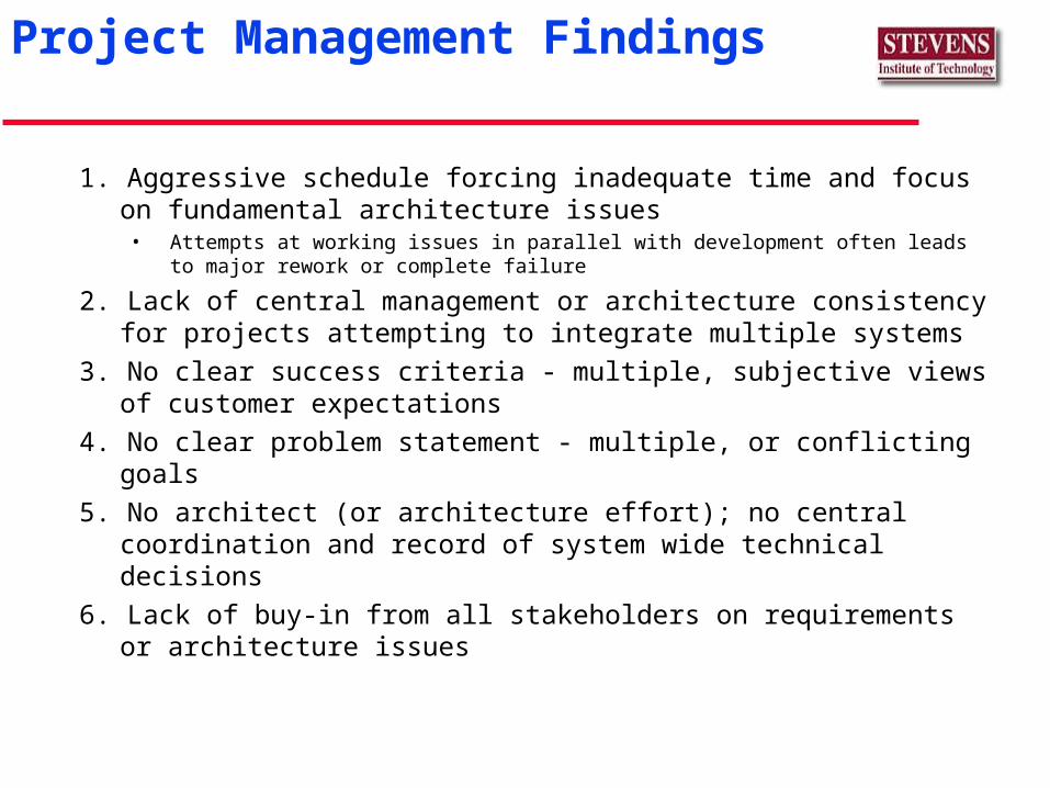
Project Management Findings
1. Aggressive schedule forcing inadequate time and focus on fundamental architecture issues
• Attempts at working issues in parallel with development often leads to major rework or complete failure
2. Lack of central management or architecture consistency for projects attempting to integrate multiple systems
3. No clear success criteria - multiple, subjective views of customer expectations
4. No clear problem statement - multiple, or conflicting goals
5. No architect (or architecture effort); no central coordination and record of system wide technical decisions
6. Lack of buy-in from all stakeholders on requirements or architecture issues
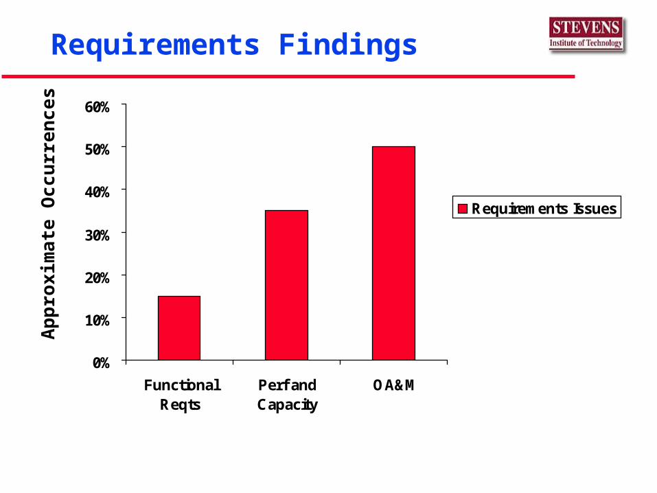
Requirements Findings
0%
10%
20%
30%
40%
50%
60%
FunctionalReqts
Perf andCapacity
OA&M
Requirements Issues
Ap
pro
xim
ate
Oc
cu
rre
nc
es
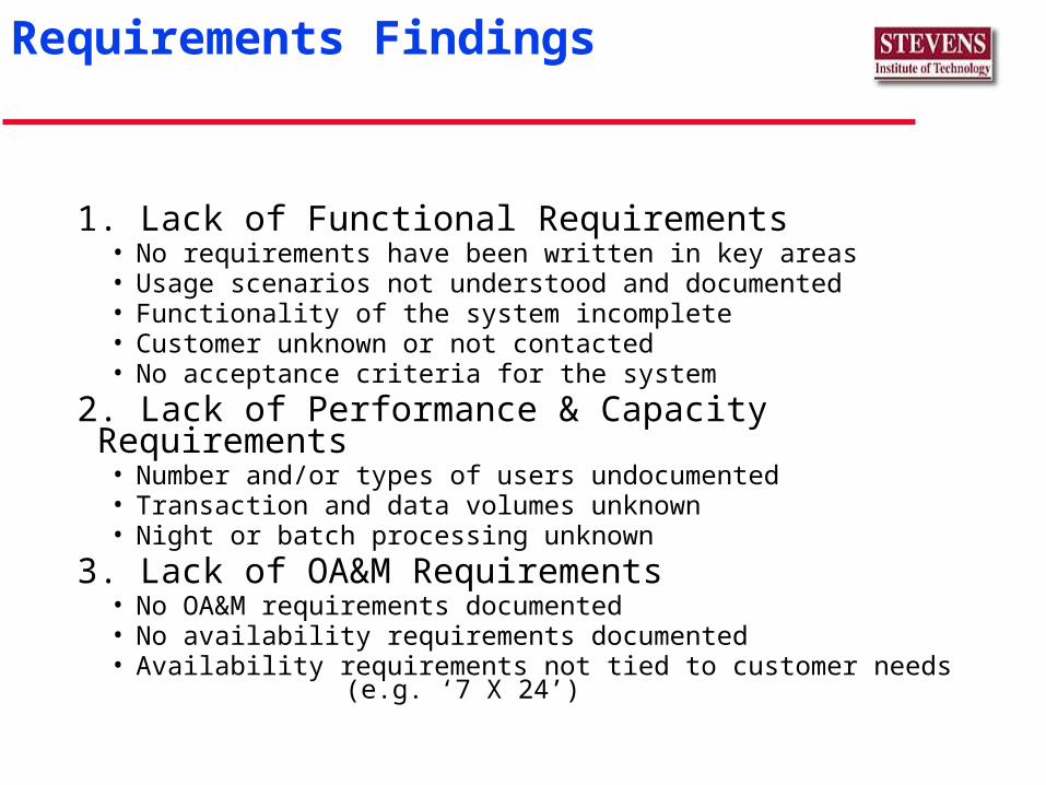
Requirements Findings
1. Lack of Functional Requirements• No requirements have been written in key areas• Usage scenarios not understood and documented• Functionality of the system incomplete• Customer unknown or not contacted• No acceptance criteria for the system
2. Lack of Performance & Capacity Requirements• Number and/or types of users undocumented• Transaction and data volumes unknown• Night or batch processing unknown
3. Lack of OA&M Requirements• No OA&M requirements documented• No availability requirements documented• Availability requirements not tied to customer needs
(e.g. ‘7 X 24’)
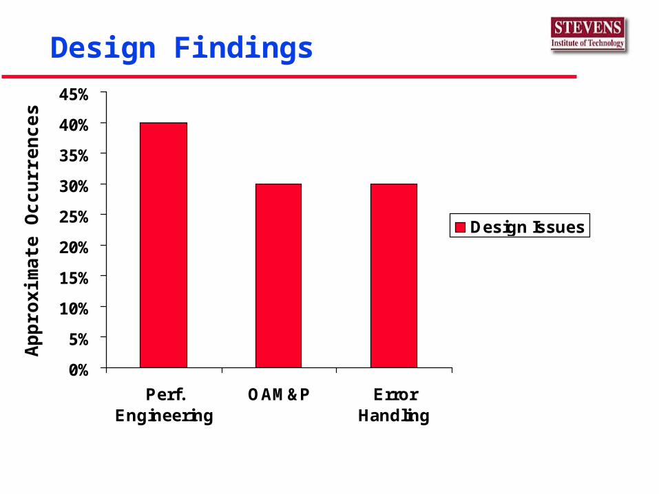
Design Findings
0%
5%
10%
15%
20%
25%
30%
35%
40%
45%
Perf.Engineering
OAM&P ErrorHandling
Design Issues
Ap
pro
xim
ate
Oc
cu
rre
nc
es
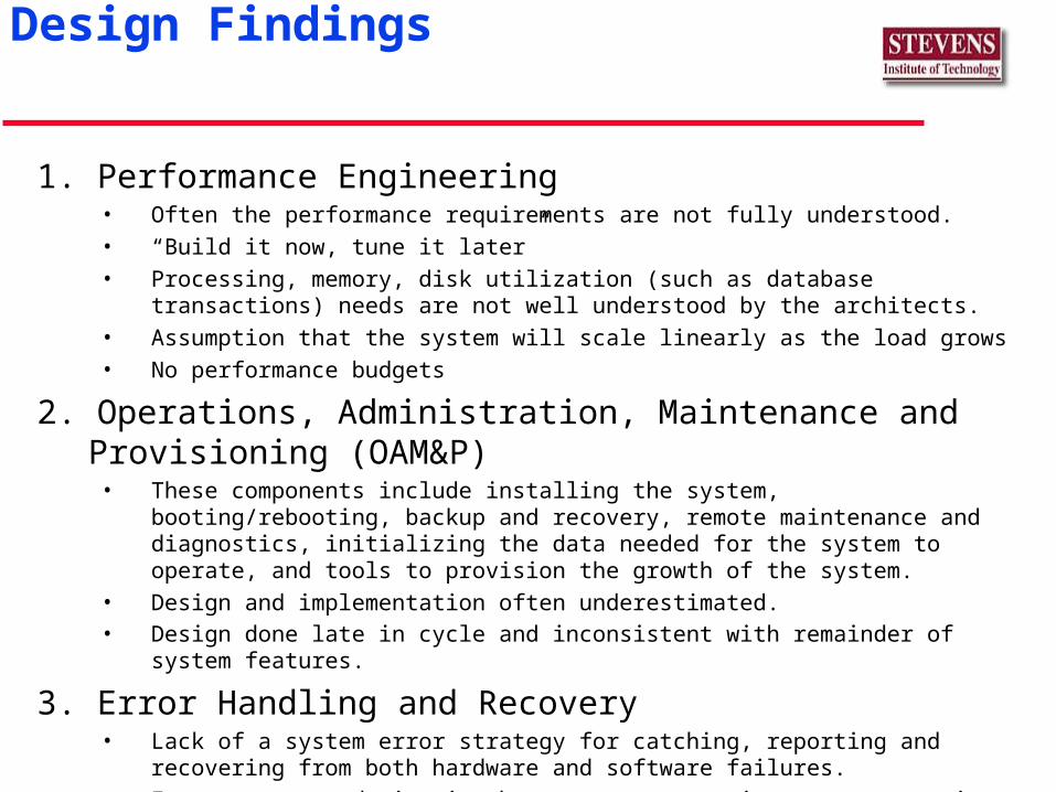
1. Performance Engineering• Often the performance requirements are not fully understood.
• “Build it now, tune it later”
• Processing, memory, disk utilization (such as database transactions) needs are not well understood by the architects.
• Assumption that the system will scale linearly as the load grows
• No performance budgets
2. Operations, Administration, Maintenance and Provisioning (OAM&P)
• These components include installing the system, booting/rebooting, backup and recovery, remote maintenance and diagnostics, initializing the data needed for the system to operate, and tools to provision the growth of the system.
• Design and implementation often underestimated.• Design done late in cycle and inconsistent with remainder of system features.
3. Error Handling and Recovery• Lack of a system error strategy for catching, reporting and recovering from both hardware
and software failures.
• Error strategy design is the process to examine error scenarios.
Design Findings
Service Capacity Planning
Goals
To support and drive service scalability targets.
To identify early architecture and network issues.
To communicate between business management and the technical community.
Scalability Overview
Capacity modeling before service deployment Periodic usage reporting as service deployed Capacity management as service deployed
• Monitoring
• Growth Planning and Implementation
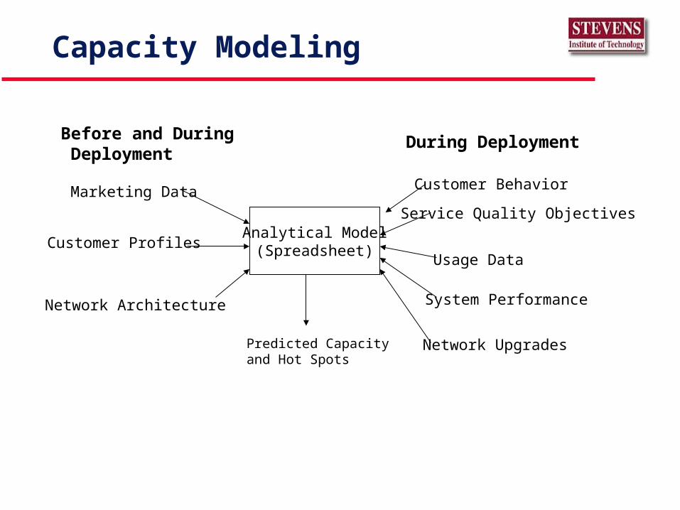
Capacity Modeling
Analytical Model(Spreadsheet)
Marketing Data
Customer Profiles
Network Architecture
Customer Behavior
Usage Data
Network UpgradesPredicted Capacityand Hot Spots
Before and During Deployment
During Deployment
Service Quality Objectives
System Performance
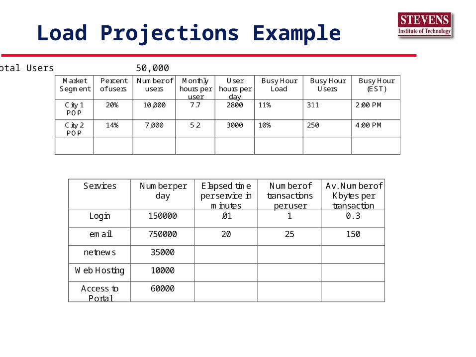
Load Projections Example
MarketSegment
Percentof users
Number ofusers
Monthlyhours per
user
Userhours per
day
Busy HourLoad
Busy HourUsers
Busy Hour(EST)
City 1POP
20% 10,000 7.7 2800 11% 311 2:00 PM
City 2POP
14% 7,000 5.2 3000 10% 250 4:00 PM
Total Users 50,000
Services Number perday
Elapsed timeper service in
minutes
Number oftransactions
per user
Av. Number ofKbytes pertransaction
Login 150000 .01 1 0. 3
email 750000 20 25 150
netnews 35000
Web Hosting 10000
Access toPortal
60000
Acknowledgement
Thanks to Joe Maranzano, he is the class of software architects.
Architecture Description Language
Thanks to Ed Colbert, USC
Problems Developing Embedded Real-Time Systems
Reliability, safety, & performance are vital concerns
Wrong or late answer can be deadly Hardware dependent integration and
migration Few means of assessing impact of decisions Upgrades throughout an extended
deployment
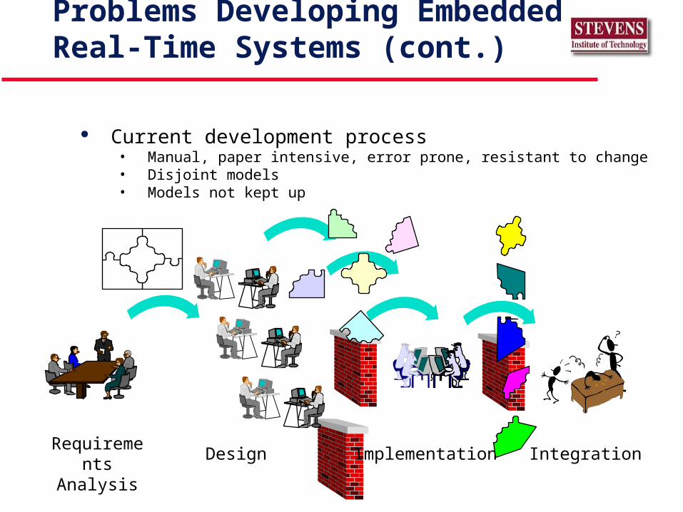
Problems Developing Embedded Real-Time Systems (cont.)
Current development process• Manual, paper intensive, error prone, resistant to change• Disjoint models• Models not kept up
Requirements Analysis
Design Implementation Integration
Ed Colbert
updated
Problems Developing Embedded Real-Time Systems (cont.)
A well–designed architecture is essential, but
• architectural descriptions are
»Informal documents
»Usually centered on box-and-line diagrams, with explanatory prose
• Visual conventions are idiosyncratic & project-specific
What is an Architecture Description Language?
Describe high-level designs
Treats systems as collections of connected modules
• Module layout defines structure
• Connectors define communication
• Iinterfaces are modules
Does NOT describe algorithms, data structures or control flows
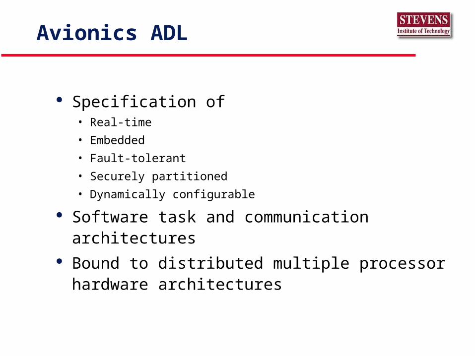
Avionics ADL
Specification of• Real-time
• Embedded
• Fault-tolerant
• Securely partitioned
• Dynamically configurable
Software task and communication architectures Bound to distributed multiple processor hardware
architectures
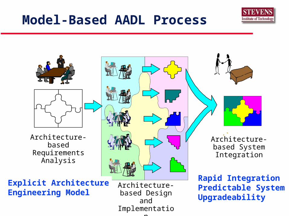
Architecture-based Requirements
Analysis
Architecture-based Design and
Implementation
Architecture-based System Integration
Model-Based AADL Process
Rapid Integration Predictable System Upgradeability
Explicit ArchitectureEngineering Model
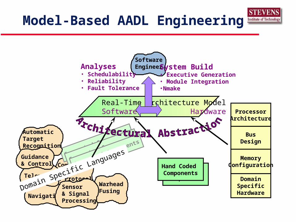
Navigation
WarheadFusing
Communi-cation& ProtocolTelemetry
Sensor& SignalProcessing
SoftwareEngineer
Real-Time Architecture ModelSoftware Hardware
System Build• Executive Generation• Module Integration•Nmake
DomainSpecific
Hardware
MemoryConfiguration
BusDesign
ProcessorArchitecture
Model-Based AADL Engineering
Generated Components
Generated Components
Generated Components
AutomaticTargetRecognition
Guidance& Control
Domain Specific Languages
Hand Coded Components
Hand Coded Components
Analyses• Schedulability• Reliability• Fault Tolerance
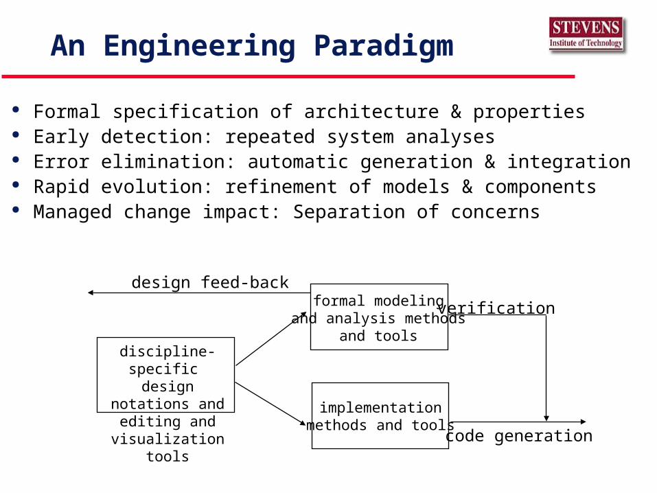
An Engineering Paradigm
Formal specification of architecture & properties Early detection: repeated system analyses Error elimination: automatic generation & integration Rapid evolution: refinement of models & components Managed change impact: Separation of concerns
discipline-specific design notations and
editing andvisualization tools
formal modelingand analysis methods
and tools
implementationmethods and tools
design feed-back
verification
code generation
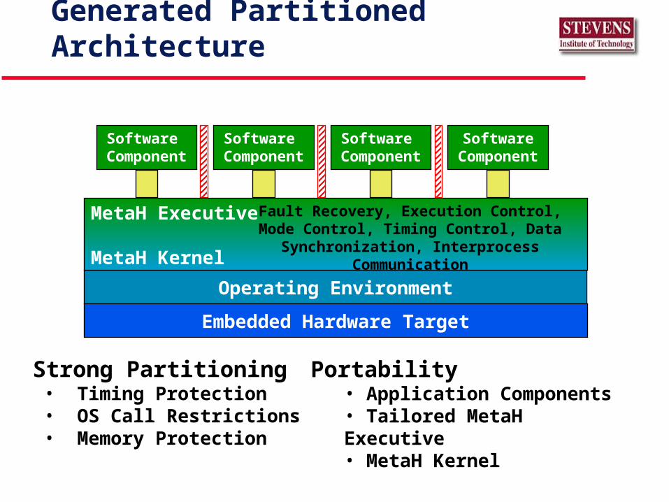
Generated Partitioned Architecture
Strong Partitioning • Timing Protection• OS Call Restrictions• Memory Protection
Portability• Application Components• Tailored MetaH Executive• MetaH Kernel
Operating Environment
Software Component
Software Component
Software Component
Embedded Hardware Target
SoftwareComponent
MetaH Executive
MetaH Kernel
Fault Recovery, Execution Control, Mode Control, Timing Control, Data Synchronization,
Interprocess Communication
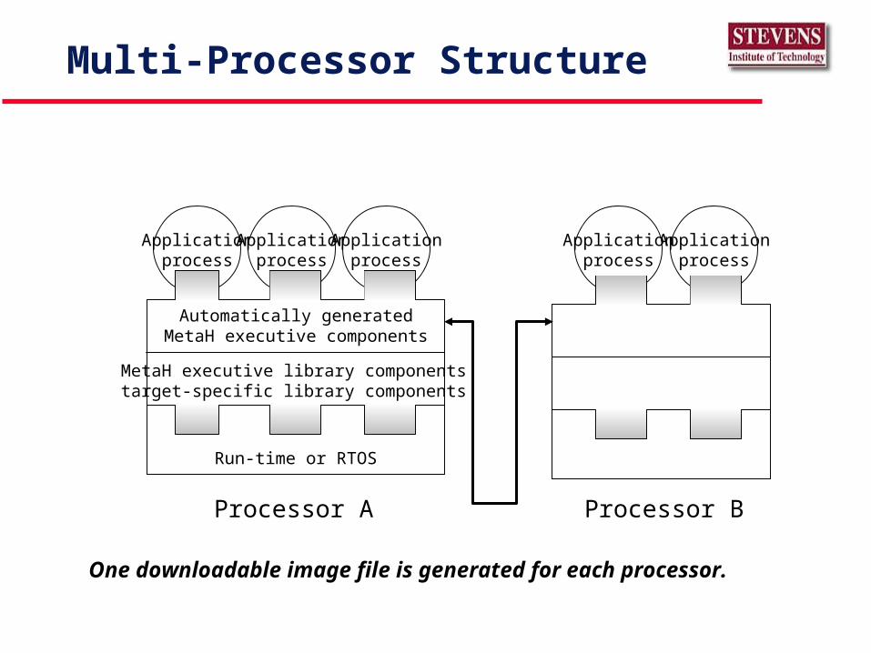
Multi-Processor Structure
Applicationprocess
Applicationprocess
Applicationprocess
Applicationprocess
Applicationprocess
Automatically generatedMetaH executive components
MetaH executive library componentstarget-specific library components
Run-time or RTOS
Processor BProcessor A
One downloadable image file is generated for each processor.
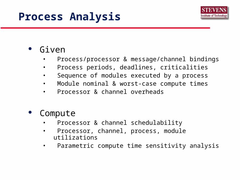
Process Analysis
Given• Process/processor & message/channel bindings• Process periods, deadlines, criticalities• Sequence of modules executed by a process• Module nominal & worst-case compute times• Processor & channel overheads
Compute• Processor & channel schedulability• Processor, channel, process, module utilizations• Parametric compute time sensitivity analysis
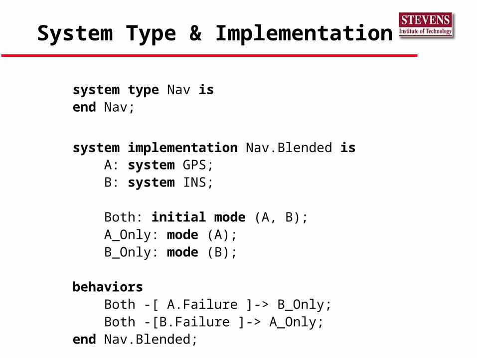
System Type & Implementation
system type Nav isend Nav;
system implementation Nav.Blended is A: system GPS; B: system INS;
Both: initial mode (A, B); A_Only: mode (A); B_Only: mode (B);
behaviors Both -[ A.Failure ]-> B_Only; Both -[B.Failure ]-> A_Only;end Nav.Blended;
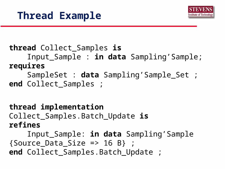
Thread Example
thread Collect_Samples is Input_Sample : in data Sampling’Sample;requires SampleSet : data Sampling’Sample_Set ;end Collect_Samples ;
thread implementation Collect_Samples.Batch_Update isrefines Input_Sample: in data Sampling’Sample {Source_Data_Size => 16 B} ;end Collect_Samples.Batch_Update ;
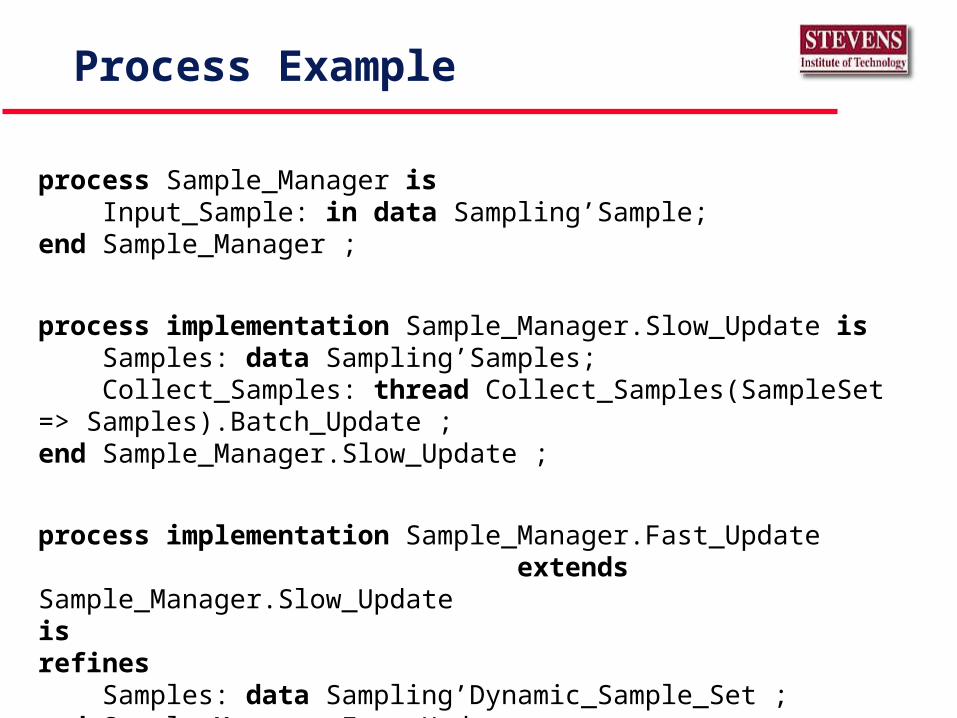
Process Example
process Sample_Manager is Input_Sample: in data Sampling’Sample;end Sample_Manager ;
process implementation Sample_Manager.Slow_Update is Samples: data Sampling’Samples; Collect_Samples: thread Collect_Samples(SampleSet => Samples).Batch_Update ;end Sample_Manager.Slow_Update ;
process implementation Sample_Manager.Fast_Update extends Sample_Manager.Slow_Updateisrefines Samples: data Sampling’Dynamic_Sample_Set ;end Sample_Manager.Fast_Update ;
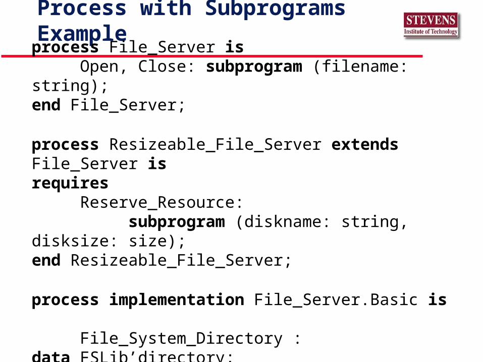
Process with Subprograms Example
process File_Server isOpen, Close: subprogram (filename: string);
end File_Server;
process Resizeable_File_Server extends File_Server isrequires
Reserve_Resource: subprogram (diskname: string, disksize: size);
end Resizeable_File_Server;
process implementation File_Server.Basic is File_System_Directory : data FSLib’directory;
end File_Server.Basic;
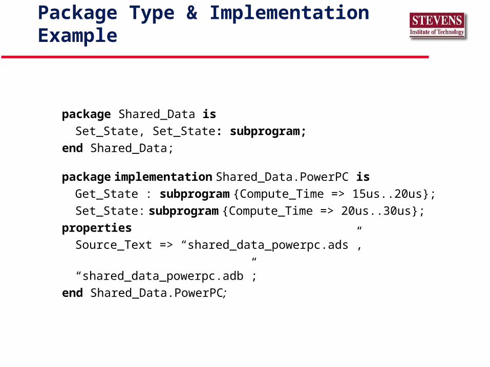
Package Type & Implementation Example
package Shared_Data is
Set_State, Set_State: subprogram;
end Shared_Data;
package implementation Shared_Data.PowerPC is
Get_State : subprogram {Compute_Time => 15us..20us};
Set_State: subprogram {Compute_Time => 20us..30us};
properties
Source_Text => “shared_data_powerpc.ads”,
“shared_data_powerpc.adb”;
end Shared_Data.PowerPC;
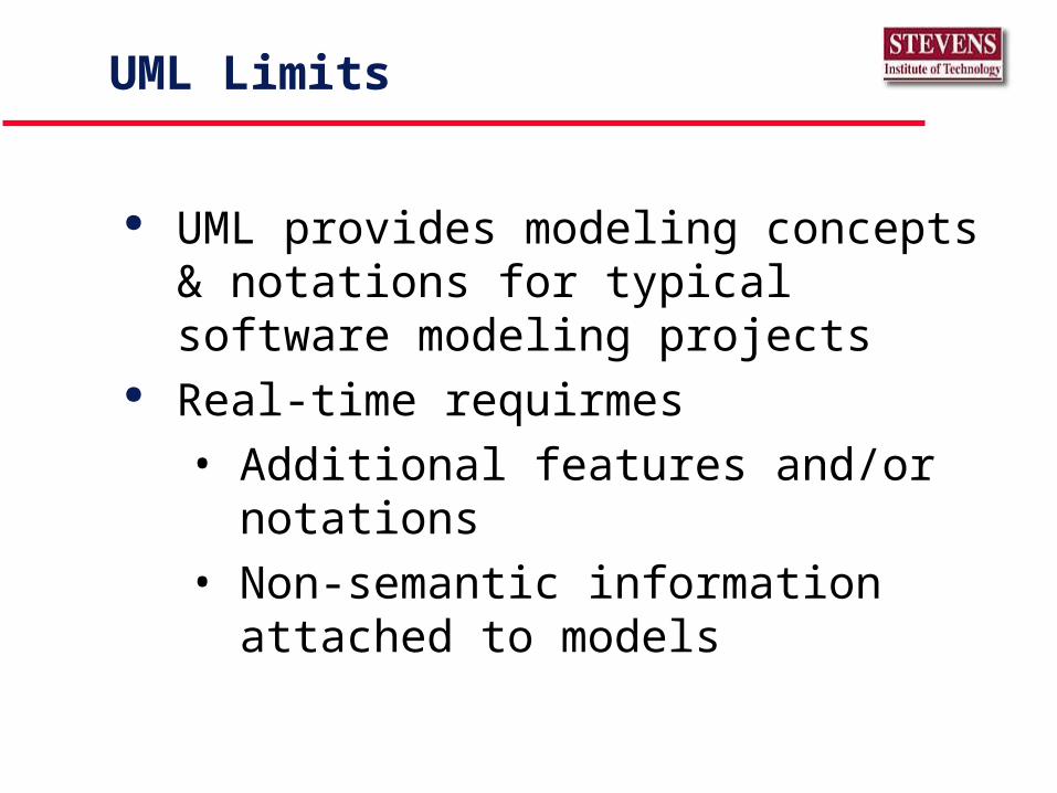
UML Limits
UML provides modeling concepts & notations for typical software modeling projects
Real-time requirmes
• Additional features and/or notations
• Non-semantic information attached to models
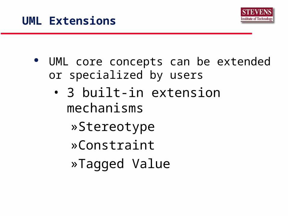
UML Extensions
UML core concepts can be extended or specialized by users
• 3 built-in extension mechanisms
»Stereotype
»Constraint
»Tagged Value
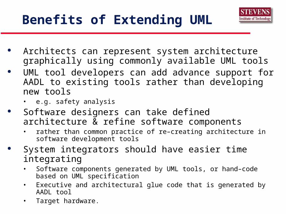
Benefits of Extending UML
Architects can represent system architecture graphically using commonly available UML tools
UML tool developers can add advance support for AADL to existing tools rather than developing new tools• e.g. safety analysis
Software designers can take defined architecture & refine software components• rather than common practice of re–creating architecture in software development
tools System integrators should have easier time integrating
• Software components generated by UML tools, or hand–code based on UML specification
• Executive and architectural glue code that is generated by AADL tool• Target hardware.
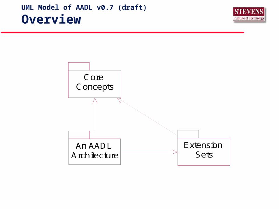
UML Model of AADL v0.7 (draft)
Overview
Core Concepts
Extension Sets
An AADL Architecture
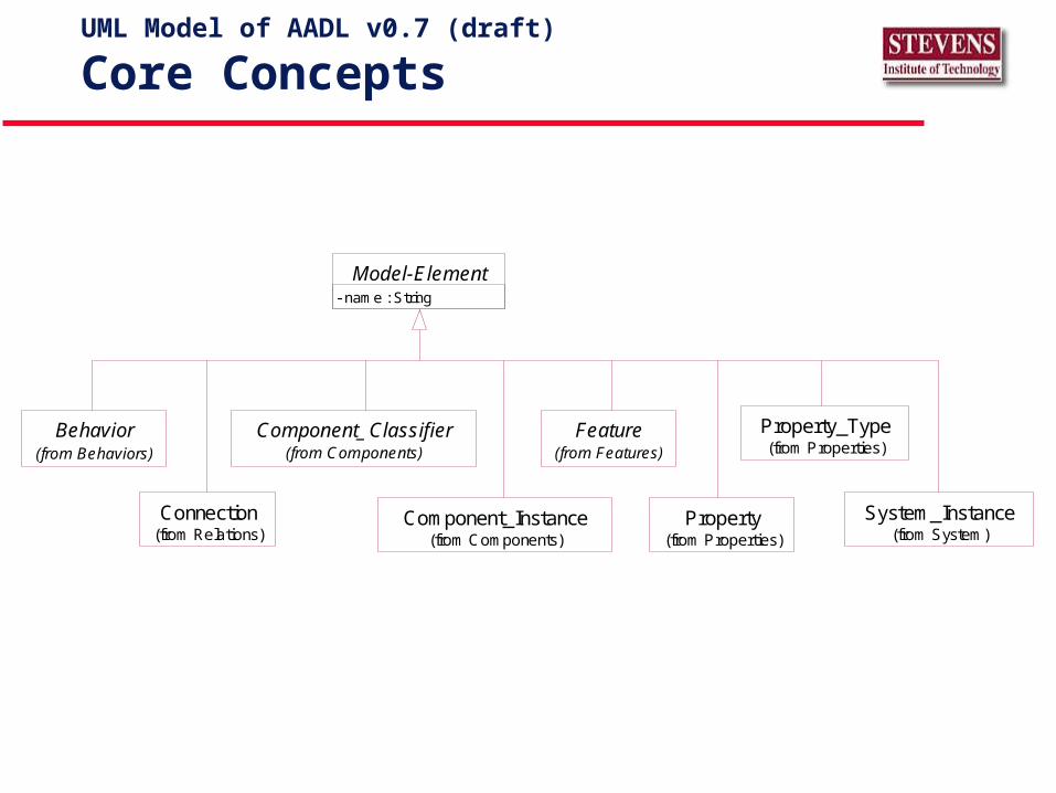
UML Model of AADL v0.7 (draft)
Core Concepts
Feature(from Features)
Model-Element- name : String
Behavior(from Behaviors)
Connection(from Relations)
Property_Type(from Properties)
Property(from Properties)
Component_Classifier(from Components)
Component_Instance(from Components)
System_Instance(from System)
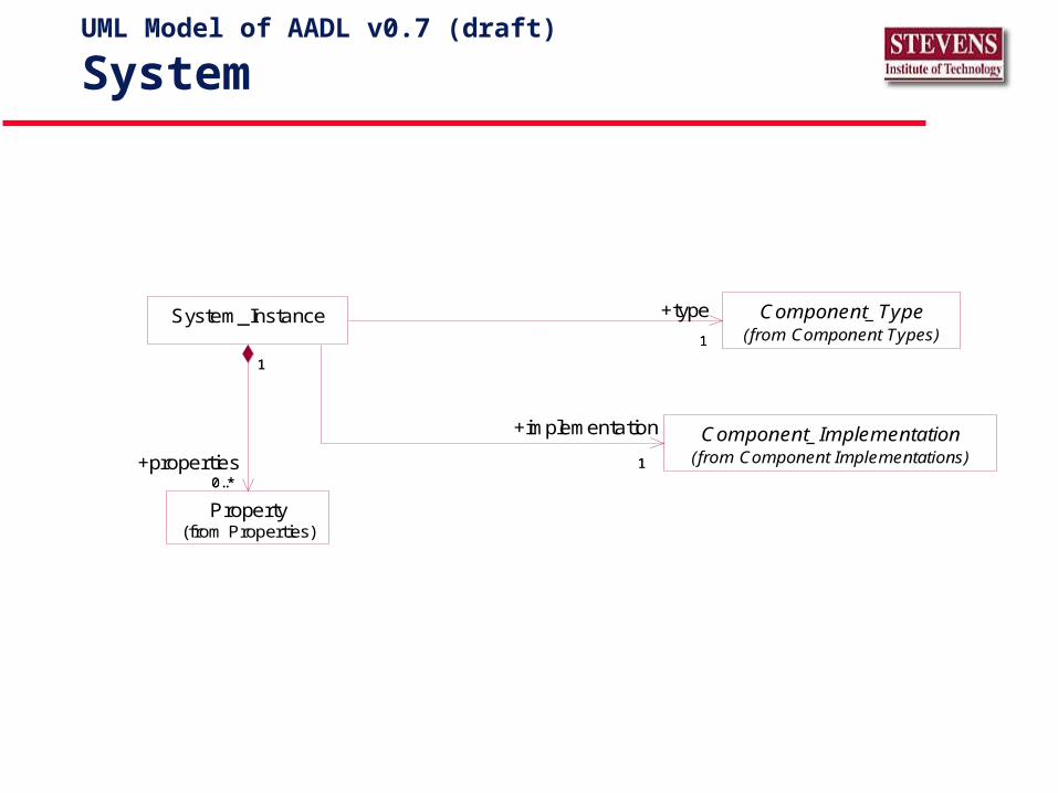
UML Model of AADL v0.7 (draft)
System
Property(from Properties)
Component_Type(from Component Types)
System_Instance
0..*
1
0..*
+properties
1
11
+type
Component_Implementation(from Component Implementations)11
+implementation
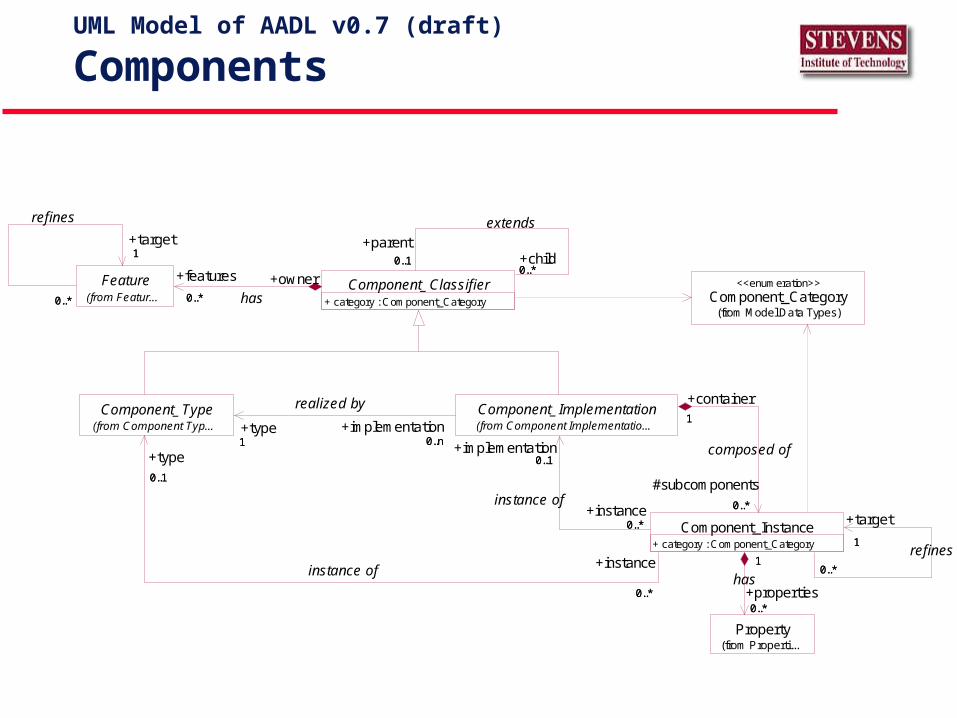
UML Model of AADL v0.7 (draft)
Components
Component_Category(from Model Data Types)
<<enumeration>>
Component_Type(from Component Typ...
Component_Implementation(from Component Implementatio...
1 0..n+type1
+implementation0..n
realized by
Property(from Properti...
Component_Instance+ category : Component_Category
0..1
0..*
+type0..1
+instance
0..*
instance of
0..1
0..*
+implementation0..1
+instance0..*
instance of
1
0..*
+container1
#subcomponents
0..*
composed of
0..*
1
+properties0..*
1
has
1
0..*
+target
1refines
0..*
Component_Classifier+ category : Component_Category
0..10..*
+parent0..1
extends
+child0..*
Feature(from Featur... 0..*
+features
0..*
+ownerhas
1
0..*
+target1
refines
0..*
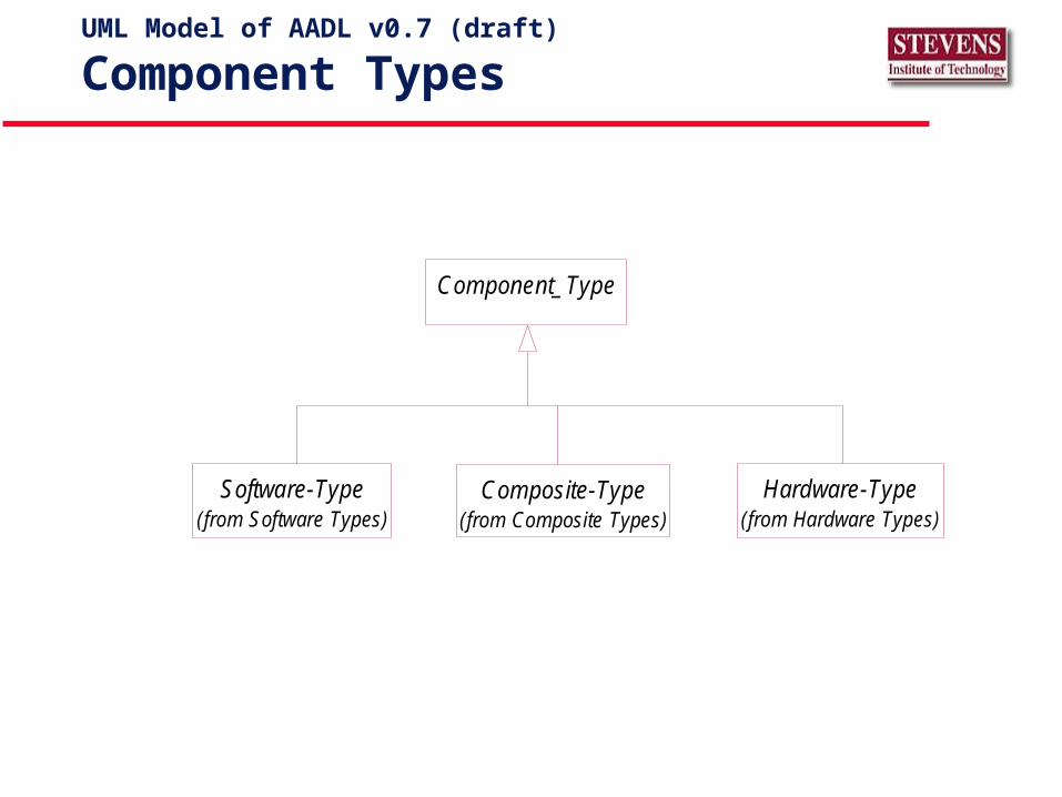
UML Model of AADL v0.7 (draft)
Component Types
Software-Type(from Software Types)
Hardware-Type(from Hardware Types)
Composite-Type(from Composite Types)
Component_Type
UML Model of AADL v0.7 (draft)
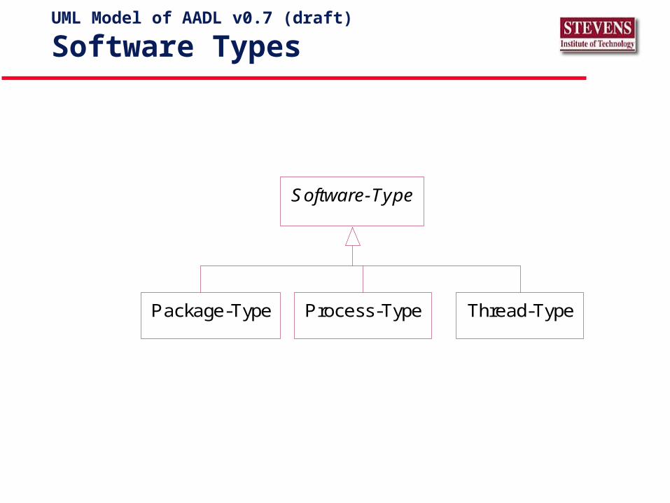
Software Types
Software-Type
Thread-TypeProcess-TypePackage-Type
UML Model of AADL v0.7 (draft)
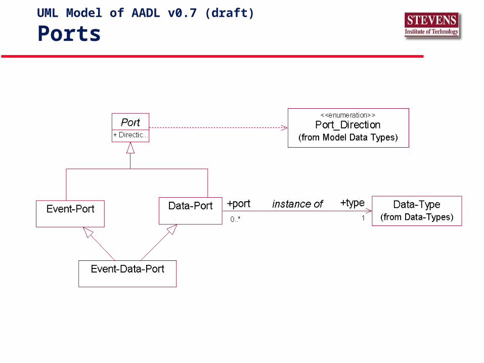
Ports
UML Model of AADL v0.7 (draft)
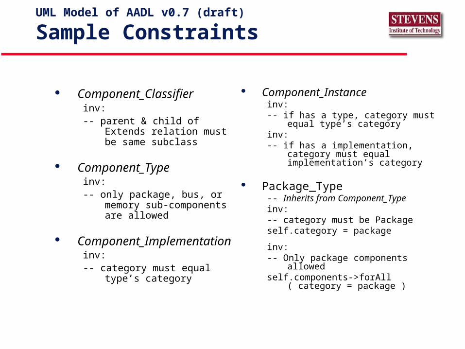
Sample Constraints
Component_Classifierinv: -- parent & child of Extends
relation must be same subclass
Component_Typeinv:-- only package, bus, or memory
sub-components are allowed
Component_Implementationinv:-- category must equal type’s
category
Component_Instanceinv:-- if has a type, category must equal type’s
categoryinv:-- if has a implementation, category must
equal implementation’s category
Package_Type-- Inherits from Component_Typeinv:-- category must be Packageself.category = package
inv:-- Only package components allowedself.components->forAll ( category =
package )
Ed Colbert
FIX
UML Model of AADL v0.7 (draft)
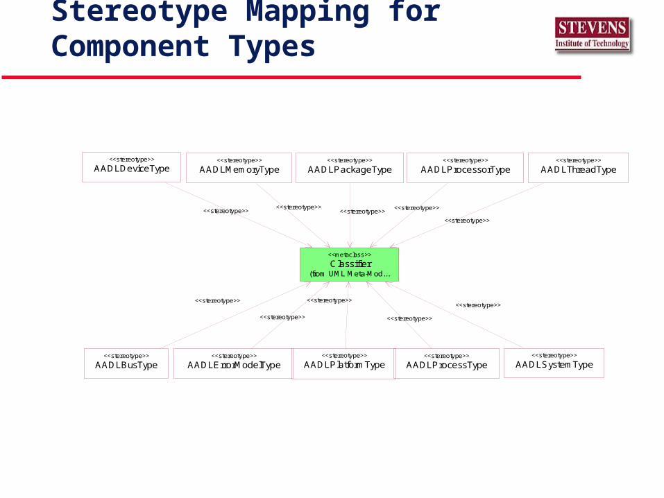
Stereotype Mapping for Component Types
AADLBusType<<stereotype>>
AADLDeviceType<<stereotype>>
AADLErrorModelType<<stereotype>>
AADLMemoryType<<stereotype>>
AADLPlatformType<<stereotype>>
AADLPackageType<<stereotype>>
AADLProcessType<<stereotype>>
AADLProcessorType<<stereotype>>
AADLSystemType<<stereotype>>
AADLThreadType<<stereotype>>
Classifier(from UML Meta-Mod...
<<metaclass>>
<<stereotype>><<stereotype>>
<<stereotype>><<stereotype>>
<<stereotype>>
<<stereotype>>
<<stereotype>>
<<stereotype>>
<<stereotype>>
<<stereotype>>
AMICOM System TypeClass Diagrams
<<AADL-system-type>>
AMICOM
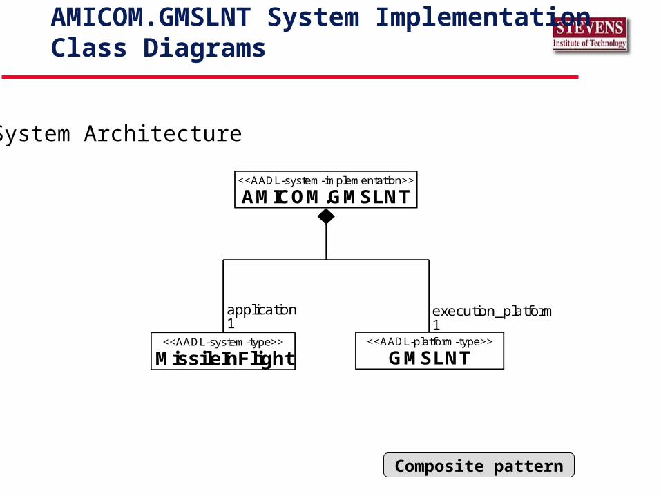
AMICOM.GMSLNT System ImplementationClass Diagrams
System Architecture
Composite pattern
<<AADL-system-implementation>>
AMICOM.GMSLNT
<<AADL-system-type>>
MissileInFlight<<AADL-platform-type>>
GMSLNT
application1
execution_platform1
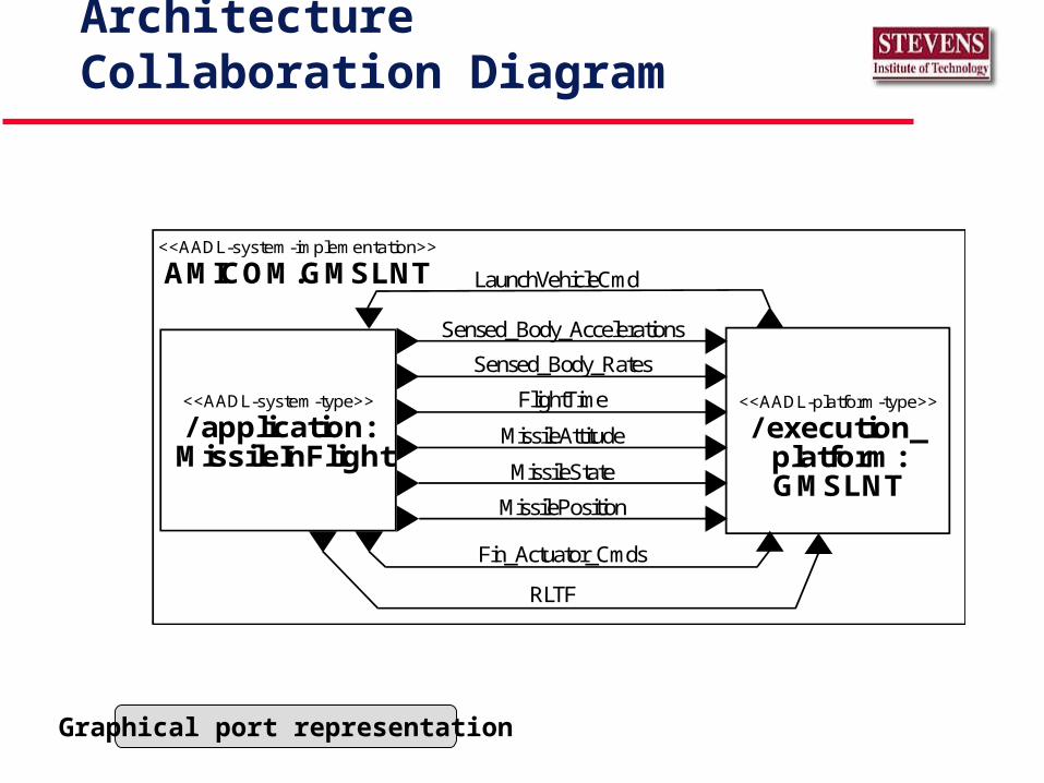
AMICOM.GMSLNT System ArchitectureCollaboration Diagram
Graphical port representation
<<AADL-platform-type>>
/ execution_platform:GMSLNT
Sensed_Body_Accelerations
Sensed_Body_Rates
FlightTime
MissileAttitude
MissileState
MissilePosition
Fin_Actuator_Cmds
RLTF
LaunchVehicleCmd<<AADL-system-implementation>>
AMICOM.GMSLNT
<<AADL-system-type>>
/ application: MissileInFlight
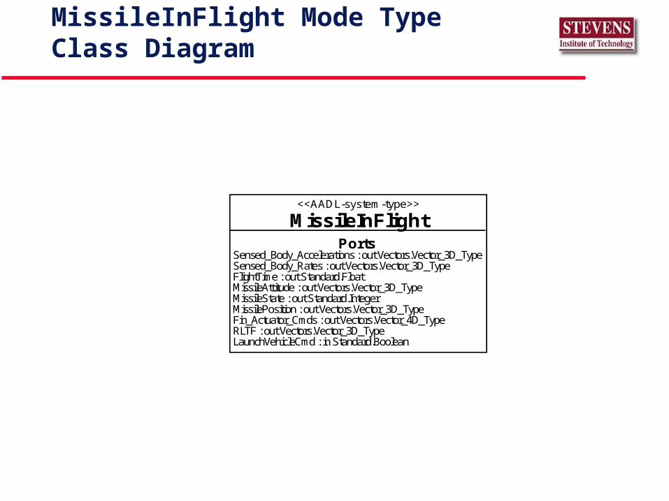
MissileInFlight Mode TypeClass Diagram
<<AADL-system-type>>
MissileInFlightPorts
Sensed_Body_Accelerations : out Vectors.Vector_3D_TypeSensed_Body_Rates : out Vectors.Vector_3D_TypeFlightTime : out Standard.FloatMissileAttitude : out Vectors.Vector_3D_TypeMissileState : out Standard.IntegerMissilePosition : out Vectors.Vector_3D_TypeFin_Actuator_Cmds : out Vectors.Vector_4D_TypeRLTF : out Vectors.Vector_3D_TypeLaunchVehicleCmd : in Standard.Boolean
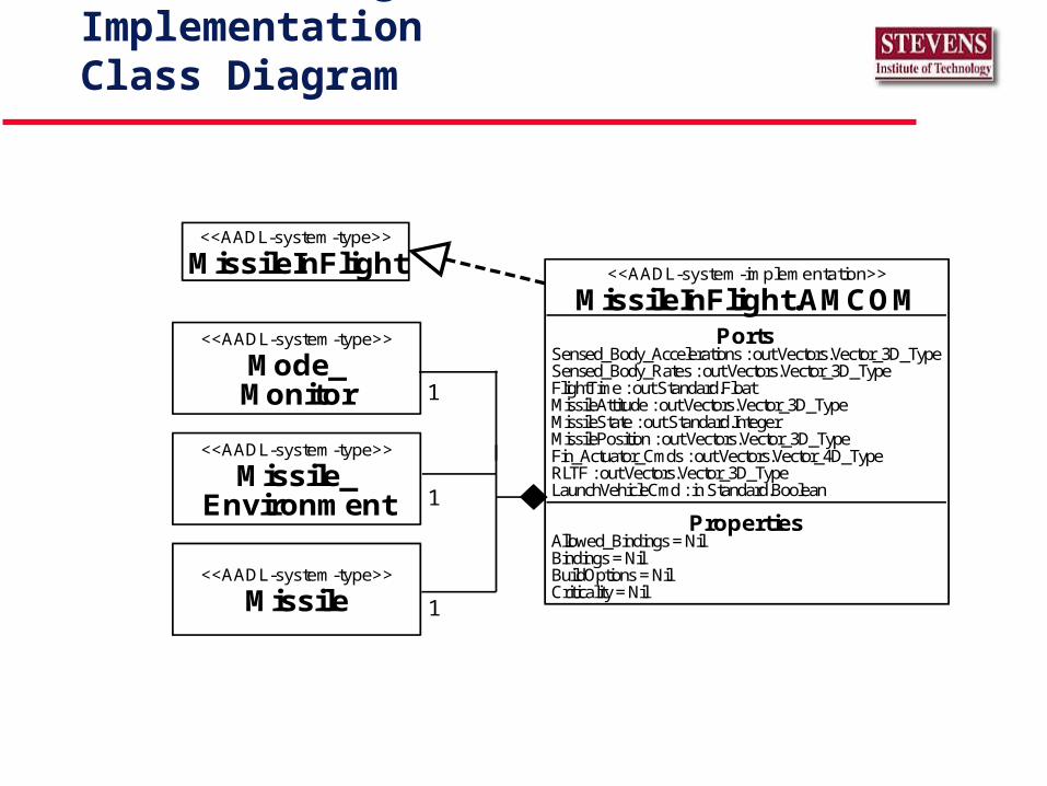
MissileInFlight.AMCOM Mode ImplementationClass Diagram
<<AADL-system-type>>
MissileInFlight <<AADL-system-implementation>>
MissileInFlight.AMCOMPorts
Sensed_Body_Accelerations : out Vectors.Vector_3D_TypeSensed_Body_Rates : out Vectors.Vector_3D_TypeFlightTime : out Standard.FloatMissileAttitude : out Vectors.Vector_3D_TypeMissileState : out Standard.IntegerMissilePosition : out Vectors.Vector_3D_TypeFin_Actuator_Cmds : out Vectors.Vector_4D_TypeRLTF : out Vectors.Vector_3D_TypeLaunchVehicleCmd : in Standard.Boolean
PropertiesAllowed_Bindings = NilBindings = NilBuildOptions = NilCriticality = Nil
1
1
<<AADL-system-type>>
Missile
<<AADL-system-type>>
Missile_Environment
<<AADL-system-type>>
Mode_Monitor 1
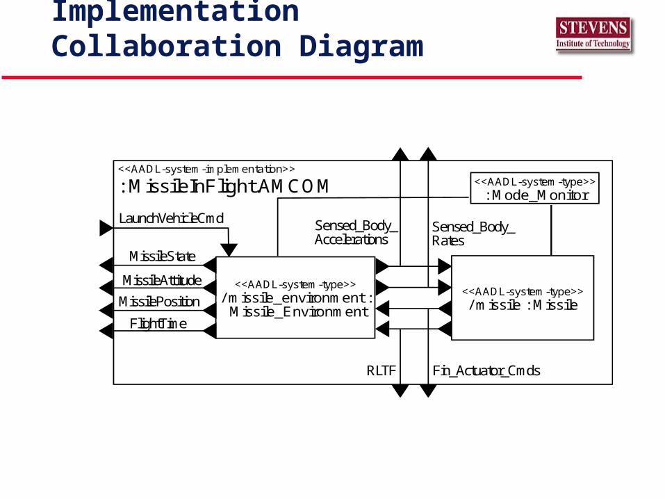
MissileInFlight.AMCOM Mode Implementation Collaboration Diagram
Sensed_Body_Accelerations
Sensed_Body_Rates
FlightTime
MissileAttitude
MissileState
MissilePosition
Fin_Actuator_CmdsRLTF
LaunchVehicleCmd
<<AADL-system-implementation>>
: MissileInFlight.AMCOM
<<AADL-system-type>>/ missile : Missile
<<AADL-system-type>>/ missile_environment : Missile_Environment
<<AADL-system-type>>: Mode_Monitor
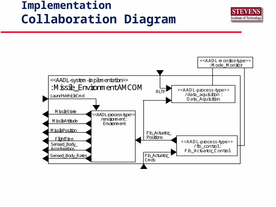
Missile_Environment.AMCOM System ImplementationCollaboration Diagram
Sensed_Body_Accelerations
Sensed_Body_Rates
FlightTime
MissileAttitude
MissileState
MissilePosition
Fin_Actuator_Cmds
RLTFLaunchVehicleCmd
<<AADL-system-implementation>>: Missile_Environment.AMCOM
<<AADL-process-type>>/ fin_control :
Fin_Actuator_Control
<<AADL-process-type>>/ environment : Environment
<<AADL-process-type>>/ data_aquisition :Data_Aquisition
Fin_Actuator_Positions
<<AADL-monitor-type>>: Mode_Monitor
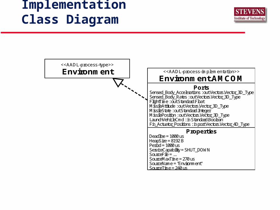
Environment.AMCOM Process ImplementationClass Diagram
<<AADL-process-type>>
Environment
PortsSensed_Body_Accelerations : out Vectors.Vector_3D_TypeSensed_Body_Rates : out Vectors.Vector_3D_TypeFlightTime : out Standard.FloatMissileAttitude : out Vectors.Vector_3D_TypeMissileState : out Standard.IntegerMissilePosition : out Vectors.Vector_3D_TypeLaunchVehicleCmd : in Standard.BooleanFin_Actuator_Positions : in port Vectors.Vector_4D_Type
PropertiesDeadline = 1000 usHeapSize = 8192 BPeriod = 1000 usServiceCapability = SHUT_DOWNSourceFile = ...SourceMaxTime = 270 usSourceName = "Environment"SourceTime = 240 us
<<AADL-process-implementation>>
Environment.AMCOM
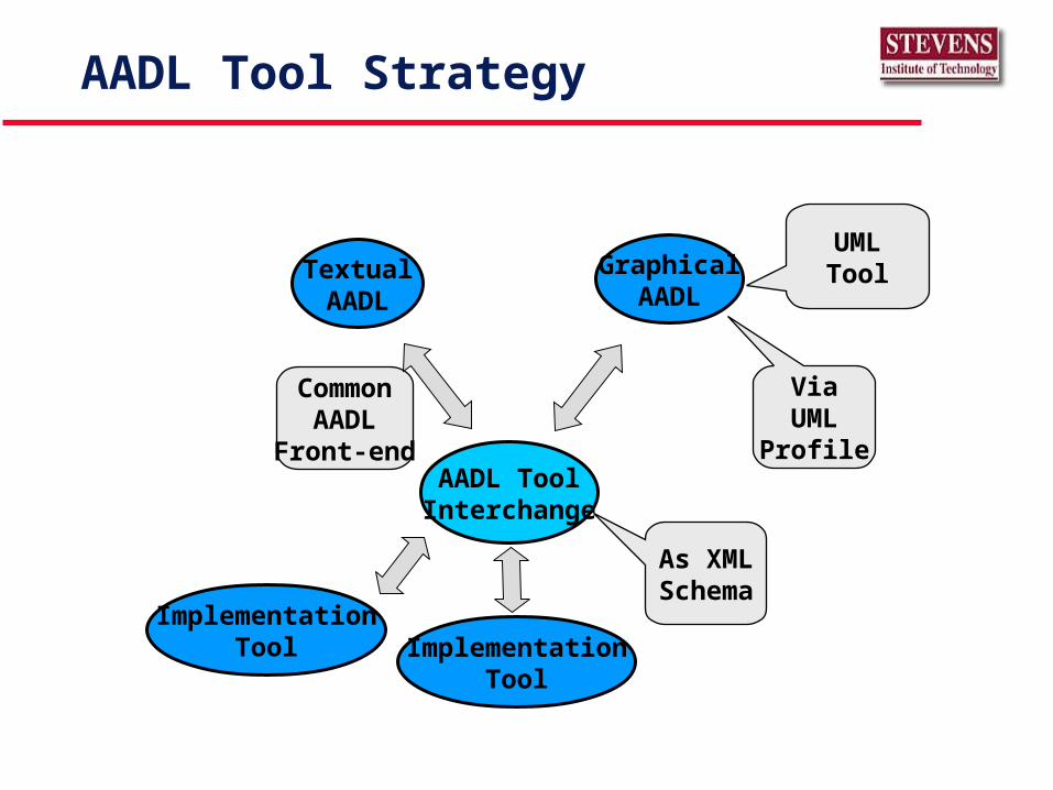
AADL Tool Strategy
AADL ToolInterchange
TextualAADL
GraphicalAADL
ViaUML
Profile
As XMLSchema
CommonAADL
Front-end
ImplementationTool Implementation
Tool
UMLTool
Things You Might Do With The AADL
Specify architecture & components for product line architecture• Create reusable components
Create adaptable workstation simulation that can be retargeted to tactical embedded system without loss of fidelity• Processing environment risk reduction (Software First).
Retargeting & re-engineering embedded systems
Things You Can Do With The AADL (cont.)
Analysis system performance of embedded RT systems• Schedule
• Safety
• Security
Generation architecture with separate component generation for rapidly evolvable systems
Build open architecture avionics systems with partitioned flight control• Reducing Validation & Verification cost
Things You Can Do With The AADL (cont.)
Safe update of software at run-time • Supports dynamic reconfiguration of designed components• Addition or changes to generated configuration
» Must be compatible with original architecture specified or update specification & analysis
• Research on implementation of partial re-loading at run-time
Build Real-Time, Safety-Critical, Client-Server System• v1:
» inc. Bound port queues, RPC’s» Implementer or user to supply scheduling mechanism» Research on
Scheduling RPC’s Certify for Level A
• v2: » Research topic
On nearly co-coincident events/procedure calls
More Information or Help
Join SAE Aviation Architecture Description Language Task Group
• Call Bruce Lewis (SAE Chair, U.S. Army AMCOM) at 256-876-3224
Information & evaluation copy of MetaH• Application form is on www.htc.honeywell.com/metah
Two to Three day training course on MetaH • Call Steve Vestal (Honeywell) at 612-951-7049
Integrated use of AADL with UML• Call Ed Colbert (Absolute Software) at 760-929-0612, www.abssw.com
References
AS-5 Embedded Computing Systems ADL Subcommittee (2003). AVIONICS ARCHITECTURE DESCRIPTION LANGUAGE (AADL) AS5506, 0.8 (Draft) ed., Society of Automotive Engineers.
Colbert, E., Lewis, B., et al. (2000). “Developing Evolvable, Embedded, Time–Critical Systems with MetaH”, 34th International Conference on Technology of Object-Oriented Languages and Systems (TOOLS 34) Proceedings. Santa Barbara, CA: IEEE Computer Society.
Garlan, D., Kompanek, A. J., et al. (2000). “Reconciling the Needs of Architectural Description with Object-Modeling Notations”, (submitted for publication).
Vestal, S. (1998). MetaH User’s Manual, 1.27 ed., Honeywell Technology Center: Minneapolis, MN.