CS 26T Plus setup guide - Extron Electronics · CS 26T Plus • Setup Guide This setup guide...
4
CS 26T Plus • Setup Guide This setup guide contains installation information about the CS 26T Plus speaker cartridge for the Extron CS 1226T Plus SpeedMount ® Ceiling Speaker System. The CS 26T Plus can be installed as a standalone speaker or in conjunction with the CS 120P plenum rated enclosure. When a CS 26T Plus speaker is installed in a CS 120P enclosure, the entire assembly is plenum rated. WARNING: Potential risk of severe injury. Installation and service must be performed by authorized personnel only. AVERTISSEMENT : Risque potentiel de blessure grave ou de mort. L’installation et l’entretien doivent être effectués par le personnel autorisé uniquement. NOTE: Installation of conduit and conduit adapters must conform to all applicable building codes and local ordinances. For hard ceiling installations, see the CS 26T Plus User Guide. 1. Remove power from all devices. NOTE: If the baffle and grille are to be painted, see the CS 26T Plus and CS 120P User Guide for more information. 2. Cut a hole for the CS 26T Plus. Use the provided cutout template to outline the hole to be cut in the ceiling tile as described below. a. Remove the ceiling tile, and draw diagonal lines across it from opposite corners to locate its center. Mark the intersection where the lines cross. b. Position the center hole of the cutout template directly over the center of the tile, marked in step 2a. c. Trace a circle on the ceiling tile as follows: For installations in ceilings that are NOT fiberglass or when installing the speakers in an open back configuration: Trace a circle around the CS 26T Plus cutout template. NOTE: The fiberglass tile adapters are not needed and can be discarded. For installations in a fiberglass ceiling with the CS 120P: NOTE: A set of fiberglass tile adapters is provided with both the CS 26T Plus and the CS 120P. Only one set is needed to install the CS 26T Plus with the CS 120P kit in fiberglass tile. i. Place the fiberglass tile adapter around the outer diameter of the template that was positioned in step 2b. ii. Trace a circle around the outer diameter of the adapter. d. Cut out the circle traced in the ceiling tile. e. Replace the ceiling tile in the ceiling. 3. Remove the adjacent ceiling tile next to the tile where the speaker will be installed. 4. Install the CS 120P or ceiling mount kit. • If using the CS 120P, see the CS 120P Setup Guide to install it. • If not using the CS 120P, attach two V-rails and one C-ring across the tile above the hole cut in step 2 (see the illustration at right). The fiberglass tile adapter is not needed. 5. Route the speaker wires through the ceiling tile hole. 6. Remove the grille carefully from the CS 26T Plus. NOTE: Grille hooks are provided for grille removal, if needed. 7. Configure the bass reflex port plate. By default, the CS 26T Plus is set up for use with the CS 120P. If not using the CS 120P, set the plate for an open-back installation. • With the CS 120P: Leave the plate in its default location. The port must be left uncovered (see A in the diagram on the following page). • Open back: The bass reflex port is uncovered by default. In the open back configuration (without the CS 120P), this port must be closed (covered). If the port is not covered: a. Use a Phillips screwdriver to remove the two screws securing the bass reflex port plate in its storage location. b. Attach the plate to the bass reflex port using the two screws that you removed in step 7a (see B in the diagram on the following page). V-rail C-ring 1
Transcript of CS 26T Plus setup guide - Extron Electronics · CS 26T Plus • Setup Guide This setup guide...
CS 26T Plus • Setup Guide
This setup guide contains installation information about the CS 26T Plus speaker cartridge for the Extron CS 1226T Plus SpeedMount® Ceiling Speaker System. The CS 26T Plus can be installed as a standalone speaker or in conjunction with the CS 120P plenum rated enclosure. When a CS 26T Plus speaker is installed in a CS 120P enclosure, the entire assembly is plenum rated.
WARNING: Potential risk of severe injury. Installation and service must be performed by authorized personnel only.
AVERTISSEMENT : Risque potentiel de blessure grave ou de mort. L’installation et l’entretien doivent être effectués par le personnel autorisé uniquement.
NOTE: Installation of conduit and conduit adapters must conform to all applicable building codes and local ordinances.
For hard ceiling installations, see the CS 26T Plus User Guide.
1. Remove power from all devices.
NOTE: If the baffle and grille are to be painted, see the CS 26T Plus and CS 120P User Guide for more information.
2. Cut a hole for the CS 26T Plus. Use the provided cutout template to outline the hole to be cut in the ceiling tile as described below.
a. Remove the ceiling tile, and draw diagonal lines across it from opposite corners to locate its center. Mark the intersection where the lines cross.
b. Position the center hole of the cutout template directly over the center of the tile, marked in step 2a.
c. Trace a circle on the ceiling tile as follows:
For installations in ceilings that are NOT fiberglass or when installing the speakers in an open back configuration: Trace a circle around the CS 26T Plus cutout template.
NOTE: The fiberglass tile adapters are not needed and can be discarded.
For installations in a fiberglass ceiling with the CS 120P:
NOTE: A set of fiberglass tile adapters is provided with both the CS 26T Plus and the CS 120P. Only one set is needed to install the CS 26T Plus with the CS 120P kit in fiberglass tile.
i. Place the fiberglass tile adapter around the outer diameter of the template that was positioned in step 2b.
ii. Trace a circle around the outer diameter of the adapter.
d. Cut out the circle traced in the ceiling tile.
e. Replace the ceiling tile in the ceiling.
3. Remove the adjacent ceiling tile next to the tile where the speaker will be installed.
4. Install the CS 120P or ceiling mount kit.
• If using the CS 120P, see the CS 120P Setup Guide to install it.
• If not using the CS 120P, attach two V-rails and one C-ring across the tile above the hole cut in step 2 (see the illustration at right). The fiberglass tile adapter is not needed.
5. Route the speaker wires through the ceiling tile hole.
6. Remove the grille carefully from the CS 26T Plus.
NOTE: Grille hooks are provided for grille removal, if needed.
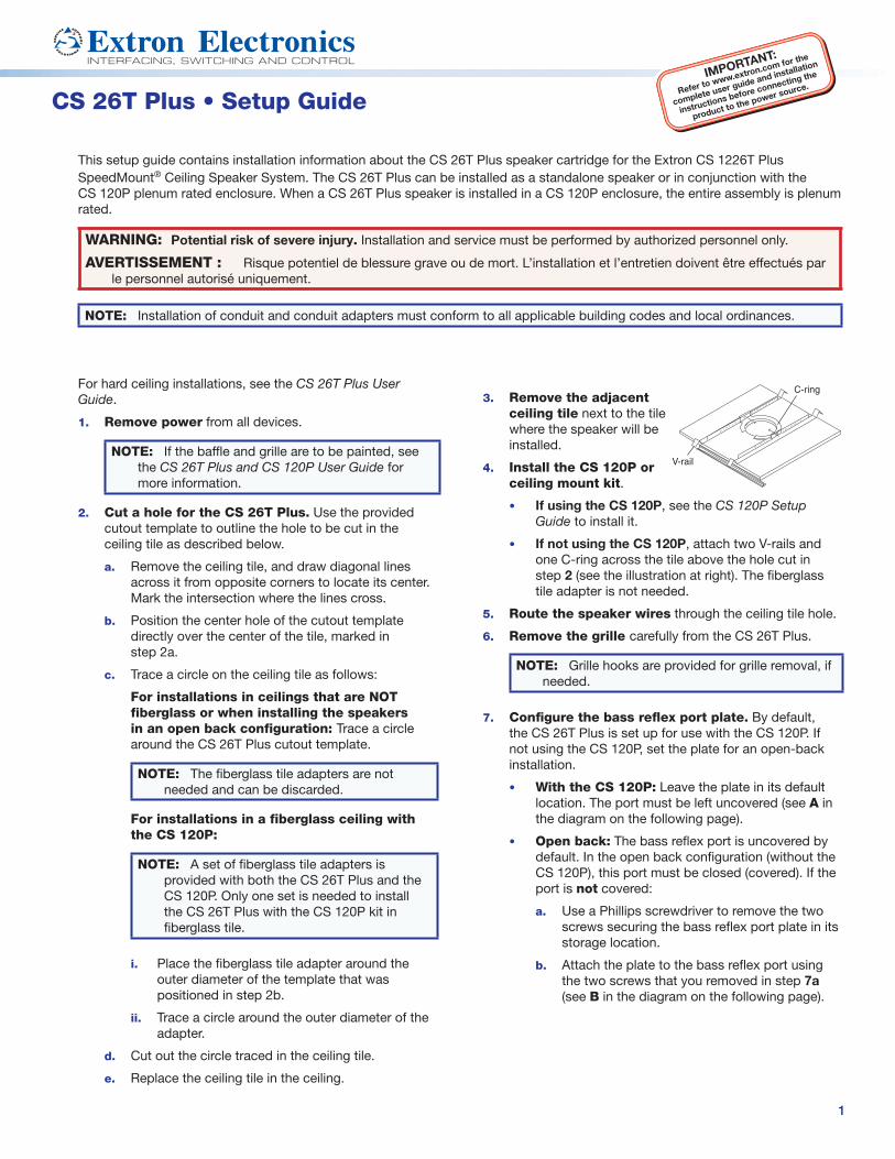
7. Configure the bass reflex port plate. By default, the CS 26T Plus is set up for use with the CS 120P. If not using the CS 120P, set the plate for an open-back installation.
• With the CS 120P: Leave the plate in its default location. The port must be left uncovered (see A in the diagram on the following page).
• Open back: The bass reflex port is uncovered by default. In the open back configuration (without the CS 120P), this port must be closed (covered). If the port is not covered:
a. Use a Phillips screwdriver to remove the two screws securing the bass reflex port plate in its storage location.
b. Attach the plate to the bass reflex port using the two screws that you removed in step 7a (see B in the diagram on the following page).
V-rail
C-ring
1
CS 26T Plus • Setup Guide (Continued)
A B
Bass Reflex Port(closed, covered)Bass Reflex Port
(open, uncovered)
Bass Port Plate(storage location)
Screws (2)
8. Attach speaker wires from the ceiling tile hole to the included 4-pole captive screw connector using one of the following three methods:
Wiring Multiple Speakers in ParallelWhen a chain of speakers is wired this way, disconnecting one speaker does not remove power from the remaining speakers in the chain.
Wiring a Single Speaker
Wiring Multiple Speakers Using Loop-through When a chain of speakers is wired this way, disconnecting one speaker removes power from all downstream speakers.
Number of Wires per Connection Point
MaximumWire Gauge
1 12 AWG
2 16 AWG
4 18 AWG
Wire Gauge Table
Speaker 1 Speaker 2
IN–
LOOP–
IN+
LOOP+
IN–
LOOP–
IN+
LOOP+
(Black)
(Red) (Red)(Red)(Black)(Black)
Power Amplifier
Speaker 1 Speaker 2
IN–
LOOP–
IN+
LOOP+
IN–
LOOP–
IN+
LOOP+
(Black)
(Red) (Red)
(Black)
Power Amplifier
(Black)
(Red)
Speaker 1
IN–
LOOP–
IN+
LOOP+
(Red)
(Black)
Power Amplifier
1
2
3
NOTES:
• See the wire gauge table above for the maximum number of wires per terminal.
• Do not tin the wires. Tinned wires do not hold tight in the captive screws and can break easily after several bends.
• See the CS 26T Plus and CS 120P User Guide for detailed information on wiring configurations.
9. Insert the captive screw plug into the four-pole receptacle on the speaker crossover board.
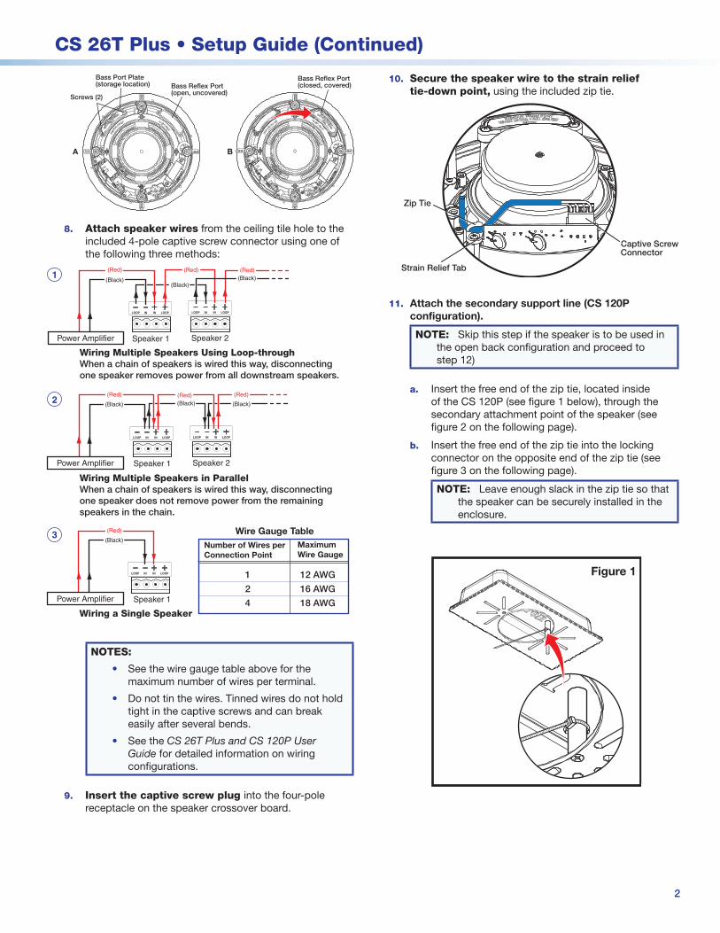
10. Secure the speaker wire to the strain relief tie-down point, using the included zip tie.
Captive ScrewConnector
Strain Relief Tab
Zip Tie
11. Attach the secondary support line (CS 120P configuration).
NOTE: Skip this step if the speaker is to be used in the open back configuration and proceed to step 12)
a. Insert the free end of the zip tie, located inside of the CS 120P (see figure 1 below), through the secondary attachment point of the speaker (see figure 2 on the following page).
b. Insert the free end of the zip tie into the locking connector on the opposite end of the zip tie (see figure 3 on the following page).
NOTE: Leave enough slack in the zip tie so that the speaker can be securely installed in the enclosure.
Figure 1
2
CS 26T Plus • Setup Guide (Continued)
3
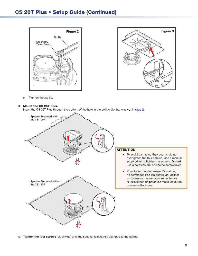
Figure 2
SecondaryTie off Point
Zip Tie
c. Tighten the zip tie.
12. Mount the CS 26T Plus. Insert the CS 26T Plus through the bottom of the hole in the ceiling tile that was cut in step 2.
Speaker Mounted with the CS 120P
Speaker Mounted without the CS 120P
13. Tighten the four screws (clockwise) until the speaker is securely clamped to the ceiling.
Figure 3
ATTENTION: • To avoid damaging the speaker, do not
overtighten the four screws. Use a manual screwdriver to tighten the screws. Do not use a cordless drill or electric screwdriver.
• Pour éviter d’endommager l’enceinte, ne serrez pas trop les quatre vis. Utilisez un tournevis manuel pour serrer les vis. N’utilisez pas de perceuse-visseuse ou de tournevis électrique.
CS 26T Plus • Setup Guide (Continued)
Extron Headquarters+800.633.9876 Inside USA/Canada Only
Extron USA - West Extron USA - East+1.714.491.1500 +1.919.850.1000
+1.714.491.1517 FAX +1.919.850.1001 FAX
Extron Europe+800.3987.6673
Inside Europe Only
+31.33.453.4040
+31.33.453.4050 FAX
Extron Asia+65.6383.4400
+65.6383.4664 FAX
Extron Japan+81.3.3511.7655
+81.3.3511.7656 FAX
Extron China+86.21.3760.1568
+86.21.3760.1566 FAX
Extron Middle East+971.4.299.1800
+971.4.299.1880 FAX
Extron Korea+82.2.3444.1571
+82.2.3444.1575 FAX
Extron India1800.3070.3777
(Inside India Only)
+91.80.3055.3777
+91.80.3055.3737 FAX
© 2015 Extron Electronics — All rights reserved. All trademarks mentioned are the property of their respective owners. www.extron.com 68-2651-50 Rev. A 07 15
4
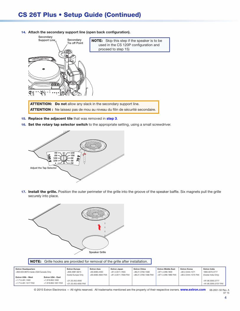
14. Attach the secondary support line (open back configuration). Secondary Support Line Secondary
Tie off Point
ATTENTION: Do not allow any slack in the secondary support line.
ATTENTION : Ne laissez pas de mou au niveau du filin de sécurité secondaire.
15. Replace the adjacent tile that was removed in step 3.
16. Set the rotary tap selector switch to the appropriate setting, using a small screwdriver.
Adjust the Tap Selector
16W32W
100 V 70 V8W
4W
8W4W2W
16W8Ω
8Ω
32W
17. Install the grille. Position the outer perimeter of the grille into the groove of the speaker baffle. Six magnets pull the grille securely into place.
Speaker Grille
NOTE: Grille hooks are provided for removal of the grille after installation.
NOTE: Skip this step if the speaker is to be used in the CS 120P configuration and proceed to step 15)