1 CS 501 Spring 2005 CS 501: Software Engineering Lecture 16 Object Oriented Design 2.
CS1402-Object Oriented Analysis and Design
© Einstein College of Engineering
CS 1042 OBJECT ORIENTED ANALYSIS AND DESIGN
UNIT 1 INRODUCTION
1.1 An Overview of Object Oriented System and Development
1.2 Object Basic
1.3 Object Oriented Systems Development Life Cycle
1.1 An Overview of Object Oriented System and Development
INTRODUCTION:
Software development is dynamic and always undergoing major change. Today a vast
number of tools and methodologies are available for system development. System
development refers to all activities that go into producing information system solution.
System development activities consist of system analysis, modelling, design,
implementation, testing and maintenance. A software development methodology is series of
processes that, if followed, can lead to the development of an application. The original goal
based on the system requirements. Further we study about the unified approach, which is the
methodology used for learning about object oriented system development.Object-Oriented
(OO) systems development is a way to develop software by building self-contained modules
that can be more easily:
Replaced
Modified
and Reused.
Orthogonal View of the Software:
A software system is a set of mechanism for performing certain action on certain data
―Algorithm + Data structure = Program‖
Object Oriented System Development Methodology:
- OO development offers a different model from the traditional software development
approach. This is based on functions and procedures.
- To develop s/w by building self contained modules or objects that can be easily
replaced, modsified and reused.
- In OO environment , s/w is a collection of discrete object that encapsulate their data
as well as the functionality to model real world ―objects‖
- Each object has attributes (data) and method (function).
- Objects grouped in to classes and object are responsible for itself
- A chart object is responsible for things like maintaining its data and labels and even
for drawing itself.
CS1402-Object Oriented Analysis and Design
© Einstein College of Engineering
Benefits of Object Orientation
Faster development,
Reusability,
Increased quality
Object technology emphasizes modeling the real world and provides us with the
stronger equivalence of the real world‘s entities (objects) than other
methodologies.
Raising the level of abstraction to the point where application can be implemented
in the same terms as they are described.
Why object orientation?
To create sets of objects that work together concurrently to produce s/w that better, model
their problem domain that similarly system produced by traditional techniques.
- It adapts to
1. Changing requirements
2. Easier to maintain
3. More robust
4. Promote greater design
5. Code reuse
- Higher level of abstraction
- Seamless transition among different phases of software development
- Encouragement of good programming techniques
- Promotion of reusability
Overview of the Unified Approach
The unified approach (UA) is a methodology for software development that is used in
this book.
The UA, based on methodologies by Booch, Rumbaugh, Jacobson, and others, tries to
combine the best practices, processes, and guidelines.
UA based on methodologies by Booch, Rumbaugh and Jacobson tries to combine the
best practices, processes and guidelines along with the object management groups in
unified modelling language.
UML is a set of notations and conventions used to describe and model an application.
UA utilizes the unified modeling language (UML) which is a set of notations and
conventions used to describe and model an application.
1.2 OBJECT BASICS:
Goals:
• Define Objects and classes
• Describe objects‘ methods, attributes and how objects respond to messages,
• Define Polymorphism, Inheritance, data abstraction, encapsulation, and protocol,
• Describe objects relationships,
CS1402-Object Oriented Analysis and Design
© Einstein College of Engineering
• Describe object persistence,
• Understand meta-classes.
What is an object?
• The term object was first formally utilized in the Similar language to simulate some
aspect of reality.
• An object is an entity.
o It knows things (has attributes)
o It does things (provides services or has methods)
Example:
It Knows things (attributes)
I am an Employee.
I know my name,
social security number and
my address.
Attributes
I am a Car.
I know my color,
manufacturer, cost,
owner and model.
It does things (methods)
I know how to
compute
my payroll.
Attributes or properties describe object‘s state (data) and methods define its behavior.
Object:
In an object-oriented system, everything is an object: numbers, arrays, records, fields,
files, forms, an invoice, etc.
An Object is anything, real or abstract, about which we store data and those methods
that manipulate the data.
Conceptually, each object is responsible for itself.
A window object is responsible for things like opening, sizing, and closing itself.
A chart object is responsible for things like maintaining its data and labels, and even
for drawing itself.
Two Basic Questions
When developing an O-O application, two basic questions always arise.
What objects does the application need?
What functionality should those objects have?

CS1402-Object Oriented Analysis and Design
© Einstein College of Engineering
Traditional Approach
• The traditional approach to software development tends toward writing a lot of code
to do all the things that have to be done.
• You are the only active entity and the code is just basically a lot of building materials.
Object-Oriented Approach
OO approach is more like creating a lot of helpers that take on an active role, a spirit,
that form a community whose interactions become the application.
Object’s Attributes
Attributes represented by data type.
They describe objects states.
In the Car example the car‘s attributes are:
color, manufacturer, cost, owner, model, etc.
Object’s Methods
Methods define objects behavior and specify the way in which an Object‘s data
are manipulated.
In the Car example the car‘s methods are:
drive it, lock it, tow it, carry passenger in it.
Objects are Grouped in Classes
The role of a class is to define the attributes and methods (the state and behavior)
of its instances.
The class car, for example, defines the property color.
Each individual car (object) will have a value for this property, such as "maroon,"
"yellow" or "white."
Class Hierarchy
An object-oriented system organizes classes into subclass-super hierarchy.
At the top of the hierarchy are the most general classes and at the bottom are the
most specific
A subclass inherits all of the properties and methods (procedures) defined in its
super class.
Motor Vehicle
Truck CarBus

CS1402-Object Oriented Analysis and Design
© Einstein College of Engineering
Inheritance (programming by extension )
Inheritance is a relationship between classes where one class is the parent class of another
(derived) class.
Inheritance allows classes to share and reuse behaviors and attributes.
The real advantage of inheritance is that we can build upon what we already have and,
Reuse what we already have.
Multiple Inheritances
OO systems permit a class to inherit from more than one superclass.
This kind of inheritance is referred to as multiple inheritance.
For example utility vehicle inherent from Car and Truck classes.
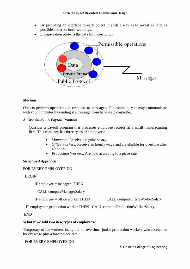
Encapsulation and Information Hiding
Information hiding is a principle of hiding internal data and procedures of an
object.
Ford
Vehicle
Car
Mustang Taurus Thunderbird
stop (myMustang)
I don‘t know how to stop
I know how to stop
stop method is reusable
MotorVehicle
Truck Car Bus
UtilityVehicle
CS1402-Object Oriented Analysis and Design
© Einstein College of Engineering
By providing an interface to each object in such a way as to reveal as little as
possible about its inner workings.
Encapsulation protects the data from corruption.
Message
Objects perform operations in response to messages. For example, you may communicate
with your computer by sending it a message from hand-help controller.
A Case Study - A Payroll Program
Consider a payroll program that processes employee records at a small manufacturing
firm. This company has three types of employees:
Managers: Receive a regular salary.
Office Workers: Receive an hourly wage and are eligible for overtime after
40 hours.
Production Workers: Are paid according to a piece rate.
Structured Approach
FOR EVERY EMPLOYEE DO
BEGIN
IF employee = manager THEN
CALL computeManagerSalary
IF employee = office worker THEN CALL computeOfficeWorkerSalary
IF employee = production worker THEN CALL computeProductionWorkerSalary
END
What if we add two new types of employees?
Temporary office workers ineligible for overtime, junior production workers who receive an
hourly wage plus a lower piece rate.
FOR EVERY EMPLOYEE DO
CS1402-Object Oriented Analysis and Design
© Einstein College of Engineering
BEGIN
IF employee = manager THEN
CALL computeManagerSalary
IF employee = office worker THEN
CALL computeOfficeWorker_salary
IF employee = production worker THEN
CALL computeProductionWorker_salary
IF employee = temporary office worker THEN
CALL computeTemporaryOfficeWorkerSalary
IF employee = junior production worker THEN
CALL computeJuniorProductionWorkerSalary
END
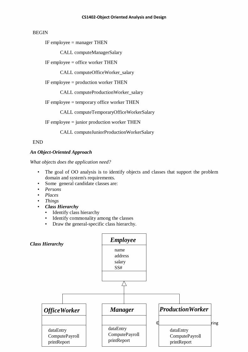
An Object-Oriented Approach
What objects does the application need?
• The goal of OO analysis is to identify objects and classes that support the problem
domain and system's requirements.
• Some general candidate classes are:
• Persons
• Places
• Things
• Class Hierarchy
• Identify class hierarchy
• Identify commonality among the classes
• Draw the general-specific class hierarchy.
Class Hierarchy
Employee
OfficeWorker Manager ProductionWorker
name
address
salary
SS#
dataEntry
ComputePayroll
printReport
dataEntry
ComputePayroll
printReport
dataEntry
ComputePayroll
printReport
CS1402-Object Oriented Analysis and Design
© Einstein College of Engineering
OO Approach
FOR EVERY EMPLOYEE DO
BEGIN
employee computePayroll
END
Polymorphism
Polymorphism means that the same operation may behave differently on different classes.
Example: computePayroll
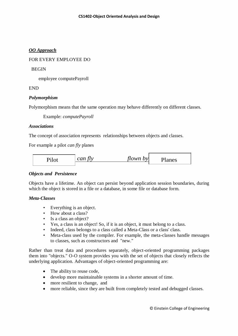
Associations
The concept of association represents relationships between objects and classes.
For example a pilot can fly planes
Objects and Persistence
Objects have a lifetime. An object can persist beyond application session boundaries, during
which the object is stored in a file or a database, in some file or database form.
Meta-Classes
• Everything is an object.
• How about a class?
• Is a class an object?
• Yes, a class is an object! So, if it is an object, it must belong to a class.
• Indeed, class belongs to a class called a Meta-Class or a class' class.
• Meta-class used by the compiler. For example, the meta-classes handle messages
to classes, such as constructors and "new."
Rather than treat data and procedures separately, object-oriented programming packages
them into "objects." O-O system provides you with the set of objects that closely reflects the
underlying application. Advantages of object-oriented programming are:
The ability to reuse code,
develop more maintainable systems in a shorter amount of time.
more resilient to change, and
more reliable, since they are built from completely tested and debugged classes.
Pilot Planescan fly flown by
CS1402-Object Oriented Analysis and Design
© Einstein College of Engineering
1.3 Object Oriented Systems Development Life Cycle
Goals
The software development process
Building high-quality software
Object-oriented systems development
Use-case driven systems development
Prototyping
Rapid application development
Component-based development
Continuous testing and reusability
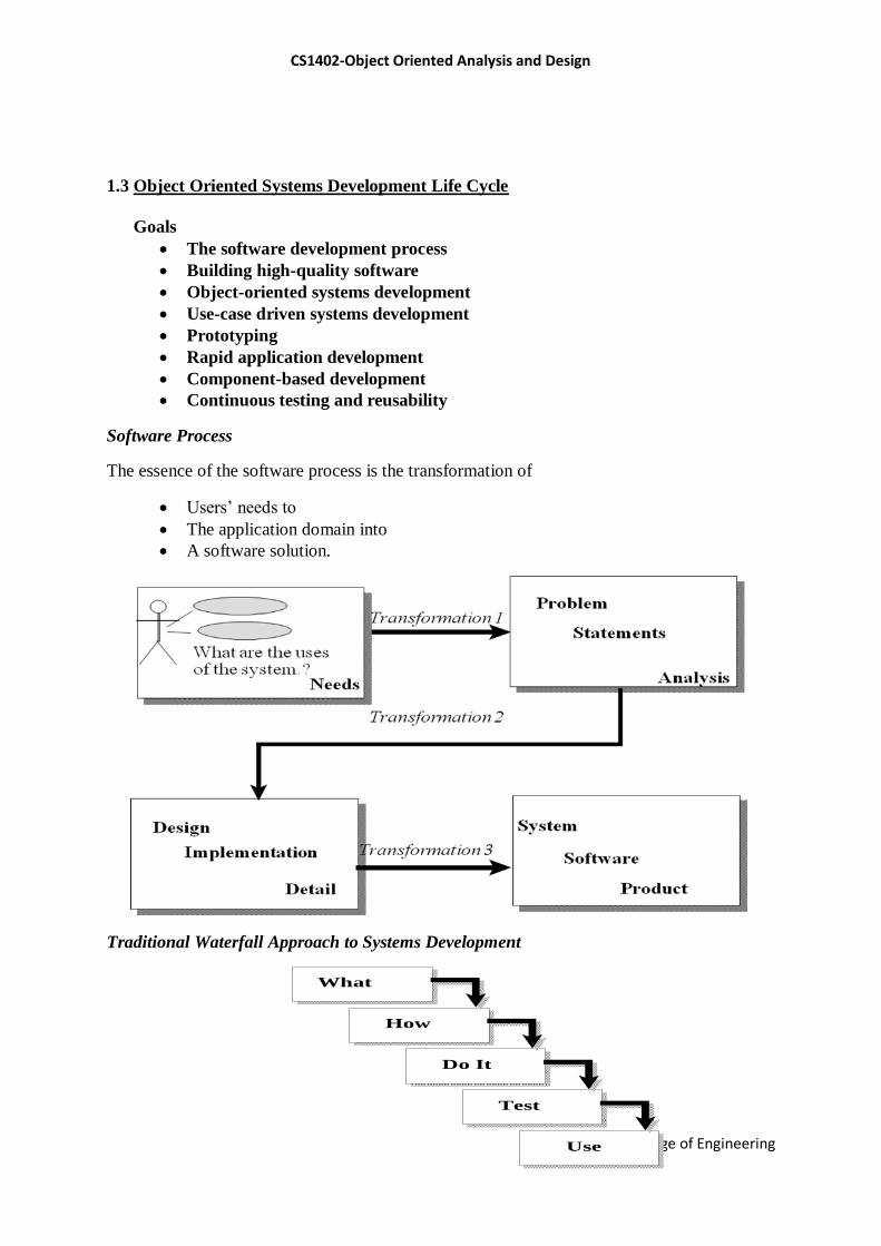
Software Process
The essence of the software process is the transformation of
Users‘ needs to
The application domain into
A software solution.
Traditional Waterfall Approach to Systems Development
What
How
Do It
Test
Use
CS1402-Object Oriented Analysis and Design
© Einstein College of Engineering
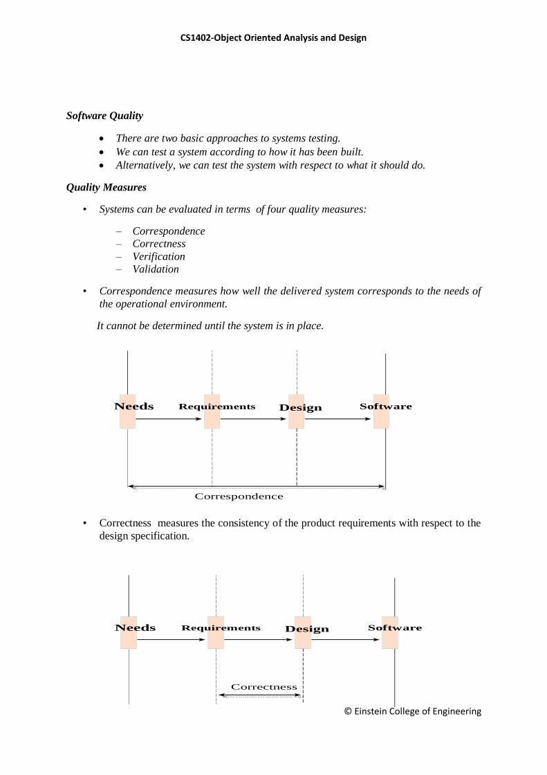
Software Quality
There are two basic approaches to systems testing.
We can test a system according to how it has been built.
Alternatively, we can test the system with respect to what it should do.
Quality Measures
• Systems can be evaluated in terms of four quality measures:
– Correspondence
– Correctness
– Verification
– Validation
• Correspondence measures how well the delivered system corresponds to the needs of
the operational environment.
It cannot be determined until the system is in place.
• Correctness measures the consistency of the product requirements with respect to the
design specification.
Design
Correspondence
SoftwareNeeds Requirements
Design
Correctness
SoftwareNeeds Requirements
CS1402-Object Oriented Analysis and Design
© Einstein College of Engineering
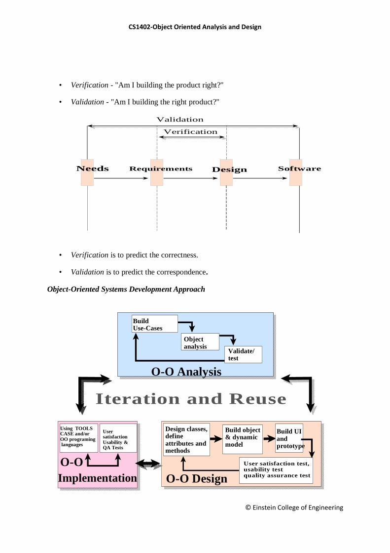
• Verification - "Am I building the product right?"
• Validation - "Am I building the right product?"
• Verification is to predict the correctness.
• Validation is to predict the correspondence.
Object-Oriented Systems Development Approach
Design
Verification
Validation
SoftwareNeeds Requirements
Iteration and Reuse
Build use-casemodel
Validate/ Test
O-O Analysis
BuildUse-Cases
Design classes,defineattributes andmethods
O-O Design
O-O
Implementation
Using TOOLSCASE and/orOO programing languages
Usersatisfaction Usability &QA Tests
Build object& dynamicmodel
Objectanalysis
Build UIandprototype
User satisfaction test,usability testquality assurance test
Validate/test

CS1402-Object Oriented Analysis and Design
© Einstein College of Engineering
Object-Oriented Systems Development activities
• Object-oriented analysis.
• Object-oriented design.
• Prototyping.
• Component-based development.
• Incremental testing.
Use-case driven systems development
Use Case, is a name for a scenario to describe the user–computer system
interaction.
Object-Oriented Analysis
OO analysis concerns with determining the system requirements and identifying
classes and their relationships that make up an application.
Object-Oriented Design
• The goal of object-oriented design (OOD) is to design
• The classes identified during the analysis phase,
• The user interface and
• Data access.
OOD activities include:
o Design and refine classes.
Design and refine attributes.
Design and refine methods.
Design and refine structures.
Design and refine associations.
o Design User Interface or View layer classes.
o Design data Access Layer classes.
Use casemodels/documnet
Dynamic model
OOA: Use caseModel
Objectinteractiondiagram, etc.
OOA: Courses ofaction
Testing: UsageScenarios
OOA: IdentifyActors
OOA: ObjectModel
OOD: Dynamicmodel
DesignclassesUI

CS1402-Object Oriented Analysis and Design
© Einstein College of Engineering
Prototyping
o A Prototype enables you to fully understand how easy or difficult it will be to
implement some of the features of the system.
o It can also give users a chance to comment on the usability and usefulness of the
design.
Types of Prototypes
o A horizontal prototype is a simulation of the interface.
o A vertical prototype is a subset of the system features with complete functionality.
o An analysis prototype is an aid for exploring the problem domain.
o A domain prototype is an aid for the incremental development of the ultimate
software solution.
Component-based development (CBD)
• CBD is an industrialized approach to the software development process.
• Application development moves from custom development to assembly of pre-built,
pre-tested, reusable software components that operate with each other.
Rapid Application Development (RAD)
• RAD is a set of tools and techniques that can be used to build an application faster
than typically possible with traditional methods.
• RAD does not replace SDLC but complements it, since it focuses more on process
description and can be combined perfectly with the object-oriented approach.
Component wrapper
Component wrapper Component wrapper
Component wrapper
Legacy screens
Legacy programs Legacy data
Legacy software packages
Subselect and enter title here
Open Connectivity
CS1402-Object Oriented Analysis and Design
© Einstein College of Engineering
Incremental Testing
• Software development and all of its activities including testing are an iterative
process.
• If you wait until after development to test an application for bugs and
performance, you could be wasting thousands of dollars and hours of time.
Reusability
A major benefit of object-oriented systems development is reusability, and this is the most
difficult promise to deliver on.
Reuse strategy
• Information hiding (encapsulation).
• Conformance to naming standards.
• Creation and administration of an object repository.
• Encouragement by strategic management of reuse as opposed to constant
redevelopment.
• Establishing targets for a percentage of the objects in the project to be reused (i.e.,
50 percent reuse of objects).
The essence of the software process is the transformation of users‘ needs into a software
solution. The O-O SDLC is an iterative process and is divided into analysis, design,
prototyping/ implementation, and testing.
CS1402-Object Oriented Analysis and Design
© Einstein College of Engineering
Unit II
OBJECT ORIENTED METHODOLOGIES
2.1 Rumbaugh Methodologies
2.2 Booch Methodology
2.3 Jacobson Methodology
2.4 Patterns
2.5 Frameworks
2.6 Unified Approach
2.7 Unified Modeling Language
2.8 Use case
2.9 Class Diagram
2.10 Interactive Diagram
2.11 Package Diagram
2.12 Collaboration Diagram
2.13 State Diagram
2.14 Activity Diagram
Basic Definition
A methodology is explained as the science of methods.
A method is a set of procedures in which a specific goal is approached step by step.
Many methodologies are available to choose from for system development.
Here, we look at the methodologies developed by Rumbaugh et al., Booch, and
Jacobson which are the origins of the Unified Modeling Language (UML) and the
bases of the UA
Strength of the Methods
• Rumbaug :Describing Object Model or the static structure of the system
• Jacobson: good for producing user-driven analysis models
• Booch : Detailed object-oriented design models
2.1. Rumbaugh Methodologies
OMT (Object Modeling Technique) describes a method for the analysis, design, and
implementation of a system using an object-oriented technique. Class attributes, method,
inheritance, and association also can be expressed easily
Phases of OMT
Analysis
System Design
Object Design

CS1402-Object Oriented Analysis and Design
© Einstein College of Engineering
Implementation
OMT consists of four phases, which can be performed iteratively:
Analysis. The results are objects and dynamic and functional models.
System design. The result is a structure of the basic architecture of the system.
Object design. This phase produces a design document, consisting of detailed objects
and dynamic and functional models.
Implementation. This activity produces reusable, extendible, and robust code.
OMT Modeling
OMT separates modeling into three different parts:
An object model, presented by the object model and the data dictionary.
A dynamic model, presented by the state diagrams and event flow diagrams.
A functional model, presented by data flow and constraints.
2. 2 Booch Methodology
The Booch methodology covers the analysis and design phases of systems
development.
Booch sometimes is criticized for his large set of symbols.
The Booch method consists of the following diagrams:
o Class diagrams
o Object diagrams
o State transition diagrams
o Module diagrams
o Process diagrams
o Interaction diagrams
Car
color
manufacturer
cost
Escort
Ford
Mustang Taurus
inherits
inherits
superclass
CS1402-Object Oriented Analysis and Design
© Einstein College of Engineering
• The Booch methodology prescribes
– A macro development process
– A micro development process.
The Macro Development Process
It servers as a controlling framework for the micro process. The primary concern is Technical
Management of the System. The macro development process consists of the following steps:
1. Conceptualization
2. Analysis and development of the model.
3. Design or create the system architecture.
4. Evolution or implementation.
5. Maintenance.
Conceptualization:
• Establish the core requirements of the system
• Establish a set of goals and develop prototype to prove the concept
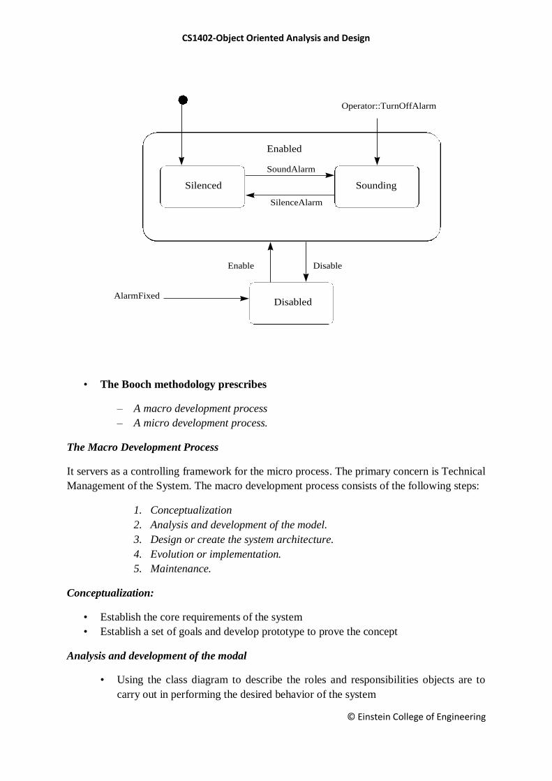
Analysis and development of the modal
• Using the class diagram to describe the roles and responsibilities objects are to
carry out in performing the desired behavior of the system
Silenced Sounding
Disabled
Enabled
SoundAlarm
SilenceAlarm
Enable Disable
Operator::TurnOffAlarm
AlarmFixed
CS1402-Object Oriented Analysis and Design
© Einstein College of Engineering
• Using the object diagram to describe the desired behavior of the system in terms
of scenarios or, alternatively
• Using the interaction diagram to describe behavior of the system in terms of
scenarios
Design or create the system architecture
• Using the class diagram to decide what mechanisms are used to regulate how
objects collaborate
• Using the module diagram to map out were each class and object should be
declared
• Using the process diagram to determine to which processor to allocate a process.
Also, determine the schedules for multiple processes on each relevant processor
Evolution or implementation
• Successively refine the system through many iterations
• Produce a stream of software implementations, each of which is refinement of the
prior one
Maintenance
• Make localized changes to the system to add new requirements and eliminate bugs
The Micro Development Process
• The micro development process consists of the following steps:
• Identify classes and objects.
• Identify class and object semantics.
• Identify class and object relationships.
• Identify class and object interfaces and implementation.
2.3 Jacobson Methodologies
The Jacobson et al. methodologies (e.g., OOBE, OOSE, and Objectory) cover the entire life
cycle and stress traceability between the different phases.
Object-Oriented Software Engineering: Objectory
• Object-oriented software engineering (OOSE), also called Objectory, is a method of
object-oriented development with the specific aim to fit the development of large,
real-time systems.
• Objectory is built around several different models:
• Use case model.
• Domain object model.
• Analysis object model. Implementation model.
CS1402-Object Oriented Analysis and Design
© Einstein College of Engineering
• Test model
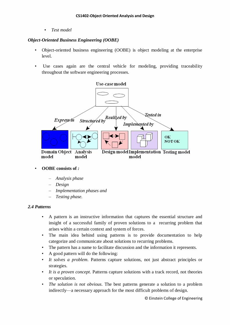
Object-Oriented Business Engineering (OOBE)
• Object-oriented business engineering (OOBE) is object modeling at the enterprise
level.
• Use cases again are the central vehicle for modeling, providing traceability
throughout the software engineering processes.
• OOBE consists of :
– Analysis phase
– Design
– Implementation phases and
– Testing phase.
2.4 Patterns
• A pattern is an instructive information that captures the essential structure and
insight of a successful family of proven solutions to a recurring problem that
arises within a certain context and system of forces.
• The main idea behind using patterns is to provide documentation to help
categorize and communicate about solutions to recurring problems.
• The pattern has a name to facilitate discussion and the information it represents.
• A good pattern will do the following:
• It solves a problem. Patterns capture solutions, not just abstract principles or
strategies.
• It is a proven concept. Patterns capture solutions with a track record, not theories
or speculation.
• The solution is not obvious. The best patterns generate a solution to a problem
indirectly—a necessary approach for the most difficult problems of design.
CS1402-Object Oriented Analysis and Design
© Einstein College of Engineering
• It describes a relationship. Patterns do not just describe modules, but describe
deeper system structures and mechanisms.
• The pattern has a significant human component.
• All software serves human comfort or quality of life; the best patterns explicitly
appeal to aesthetics and utility.
2.5 Frameworks
• A framework is a way of presenting a generic solution to a problem that can be
applied to all levels in a development.
• A single framework typically encompasses several design patterns and can be viewed
as the implementation of a system of design patterns.
Differences Between Design Patterns and Frameworks
• Design patterns are more abstract than frameworks.
• Design patterns are smaller architectural elements than frameworks.
• Design patterns are less specialized than frameworks.
2.6 The Unified Approach
• The idea behind the UA is not to introduce yet another methodology.
• The main motivation here is to combine the best practices, processes, methodologies,
and guidelines along with UML notations and diagrams.
The Unified Approach (UA)
• The unified approach to software development revolves around (but is not limited to)
the following processes and components.
• The UA processes are:
• Use-case driven development.
• Object-oriented analysis.
• Object-oriented design.
• Incremental development and prototyping.
• Continuous testing.
UA Methods and Technology
• Unified modeling language (UML) used for modeling.
• Layered approach.
• Repository for object-oriented system development patterns and frameworks.
• Promoting Component-based development.
CS1402-Object Oriented Analysis and Design
© Einstein College of Engineering
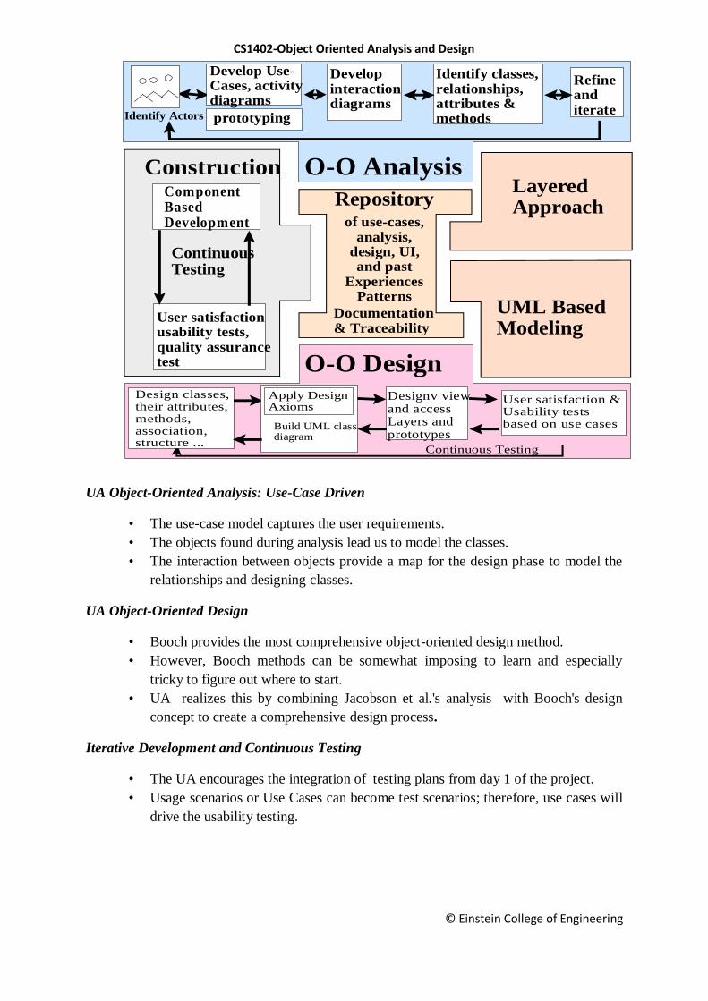
UA Object-Oriented Analysis: Use-Case Driven
• The use-case model captures the user requirements.
• The objects found during analysis lead us to model the classes.
• The interaction between objects provide a map for the design phase to model the
relationships and designing classes.
UA Object-Oriented Design
• Booch provides the most comprehensive object-oriented design method.
• However, Booch methods can be somewhat imposing to learn and especially
tricky to figure out where to start.
• UA realizes this by combining Jacobson et al.'s analysis with Booch's design
concept to create a comprehensive design process.
Iterative Development and Continuous Testing
• The UA encourages the integration of testing plans from day 1 of the project.
• Usage scenarios or Use Cases can become test scenarios; therefore, use cases will
drive the usability testing.
Documentation & Traceability
of use-cases,analysis,
design, UI,and past
ExperiencesPatterns
Repository
UML BasedModeling
ConstructionComponentBasedDevelopment
User satisfactionusability tests,quality assurancetest
Continuous Testing
RefineanditerateIdentify Actors
Develop Use-Cases, activitydiagrams
Developinteractiondiagrams
Identify classes,relationships,attributes &methods
Continuous Testing
Designv viewand accessLayers andprototypes
Apply DesignAxioms
Design classes,their attributes,methods,association,structure ...
User satisfaction &Usability tests based on use casesBuild UML class
diagram
O-O Analysis
O-O Design
LayeredApproach
prototyping
CS1402-Object Oriented Analysis and Design
© Einstein College of Engineering
Modeling Based on the Unified Modeling Language
• The UA uses the unified modeling language (UML) to describe and model the
analysis and design phases of system development.
The UA Proposed Repository
• The requirement, analysis, design, and implementation documents should be
stored in the repository, so reports can be run on them for traceability.
• This allows us to produce designs that are traceable across requirements, analysis,
design, implementation, and testing.
The Layered Approach to Software Development
Most systems developed with today's CASE tools or client-server application
development environments tend to lean toward what is known as two-layered
architecture: interface and data.
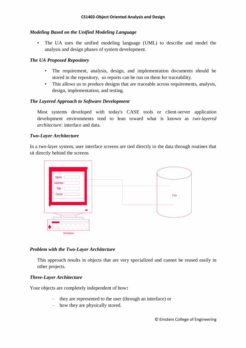
Two-Layer Architecture
In a two-layer system, user interface screens are tied directly to the data through routines that
sit directly behind the screens
Problem with the Two-Layer Architecture
This approach results in objects that are very specialized and cannot be reused easily in
other projects.
Three-Layer Architecture
Your objects are completely independent of how:
– they are represented to the user (through an interface) or
– how they are physically stored.
Data
Workstation
Owner
Name
Title
Address

CS1402-Object Oriented Analysis and Design
© Einstein College of Engineering
User Interface layer
This layer is typically responsible for two major aspects of the applications:
• Responding to user interaction
• Displaying business objects.
Business Layer
• The responsibilities of the business layer are very straight- forward:
• model the objects of the business and how they interact to accomplish the business
processes.
Business Layer: Real Objects
These objects should not be responsible for:
1. Displaying details
2. Data access details
Data
Workstation
Owner
Name
Title
Address
CS1402-Object Oriented Analysis and Design
© Einstein College of Engineering
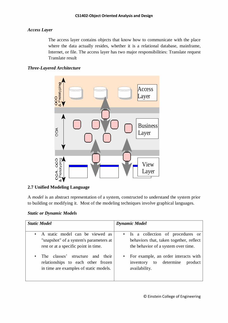
Access Layer
The access layer contains objects that know how to communicate with the place
where the data actually resides, whether it is a relational database, mainframe,
Internet, or file. The access layer has two major responsibilities: Translate request
Translate result
Three-Layered Architecture
2.7 Unified Modeling Language
A model is an abstract representation of a system, constructed to understand the system prior
to building or modifying it. Most of the modeling techniques involve graphical languages.
Static or Dynamic Models
Static Model
Dynamic Model
• A static model can be viewed as
"snapshot" of a system's parameters at
rest or at a specific point in time.
• The classes‘ structure and their
relationships to each other frozen
in time are examples of static models.
• Is a collection of procedures or
behaviors that, taken together, reflect
the behavior of a system over time.
• For example, an order interacts with
inventory to determine product
availability.
BusinessLayer
ViewLayer
Access Layer
CS1402-Object Oriented Analysis and Design
© Einstein College of Engineering
Why Modeling?
Turban cites the following advantages:
Models make it easier to express complex ideas.
For example, an architect builds a model to communicate ideas more easily to
clients.
Advantages of Modeling
Models reduce complexity by separating those aspects that are unimportant from
those that are important.
Models enhance learning.
The cost of the modeling analysis is much lower than the cost of similar
experimentation conducted with a real system.
Manipulation of the model (changing variables) is much easier than manipulating a
real system.
Modeling Key Ideas
A model is rarely correct on the first try.
Always seek the advice and criticism of others.
Avoid excess model revisions, as they can distort the essence of your model. Let
simplicity and elegance guide you through the process.
What Is the UML?
The Unified Modeling Language (UML) is a language for
Specifying
Visualizing
Constructing
Documenting
the software system and its components.
What it is/isn’t?
Is NOT
• A process
• A formalism
Is
• A way to describe your software
• more precise than English
• less detailed than code
CS1402-Object Oriented Analysis and Design
© Einstein College of Engineering
What is UML Used For?
Trace external interactions with the software
Plan the internal behavior of the application
Study the software structure
View the system architecture
Trace behavior down to physical components
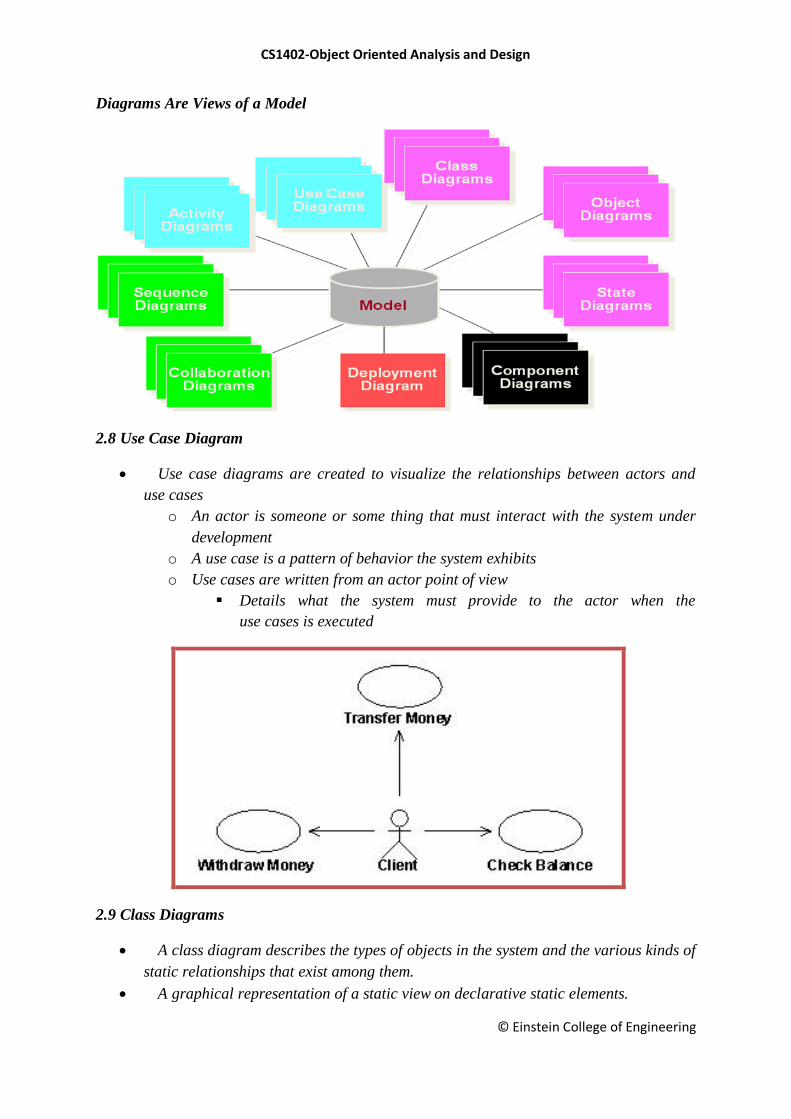
UML Diagrams
The UML defines nine graphical diagrams:
1. Class diagram (static)
2. Use-case diagram
3. Behavior diagrams (dynamic):
– 3.1. Interaction diagram:
• 3.1.1. Sequence diagram
• 3.1.2. Collaboration diagram
– 3.2. State chart diagram
– 3.3. Activity diagram
4. Implementation diagram:
4.1. Component diagram
4.2. Deployment diagram
CS1402-Object Oriented Analysis and Design
© Einstein College of Engineering
Diagrams Are Views of a Model
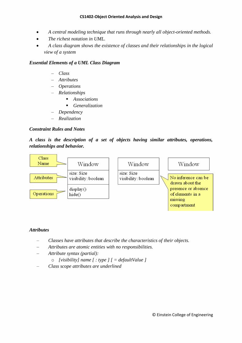
2.8 Use Case Diagram
Use case diagrams are created to visualize the relationships between actors and
use cases
o An actor is someone or some thing that must interact with the system under
development
o A use case is a pattern of behavior the system exhibits
o Use cases are written from an actor point of view
Details what the system must provide to the actor when the
use cases is executed
2.9 Class Diagrams
A class diagram describes the types of objects in the system and the various kinds of
static relationships that exist among them.
A graphical representation of a static view on declarative static elements.
CS1402-Object Oriented Analysis and Design
© Einstein College of Engineering
A central modeling technique that runs through nearly all object-oriented methods.
The richest notation in UML.
A class diagram shows the existence of classes and their relationships in the logical
view of a system
Essential Elements of a UML Class Diagram
– Class
– Attributes
– Operations
– Relationships
Associations
Generalization
– Dependency
– Realization
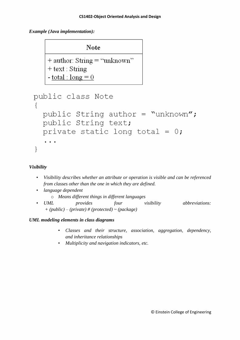
Constraint Rules and Notes
A class is the description of a set of objects having similar attributes, operations,
relationships and behavior.
Attributes
– Classes have attributes that describe the characteristics of their objects.
– Attributes are atomic entities with no responsibilities.
– Attribute syntax (partial):
o [visibility] name [ : type ] [ = defaultValue ]
– Class scope attributes are underlined
CS1402-Object Oriented Analysis and Design
© Einstein College of Engineering
Example (Java implementation):
Visibility
• Visibility describes whether an attribute or operation is visible and can be referenced
from classes other than the one in which they are defined.
• language dependent
o Means different things in different languages
• UML provides four visibility abbreviations:
+ (public) – (private) # (protected) ~ (package)
UML modeling elements in class diagrams
• Classes and their structure, association, aggregation, dependency,
and inheritance relationships
• Multiplicity and navigation indicators, etc.
CS1402-Object Oriented Analysis and Design
© Einstein College of Engineering
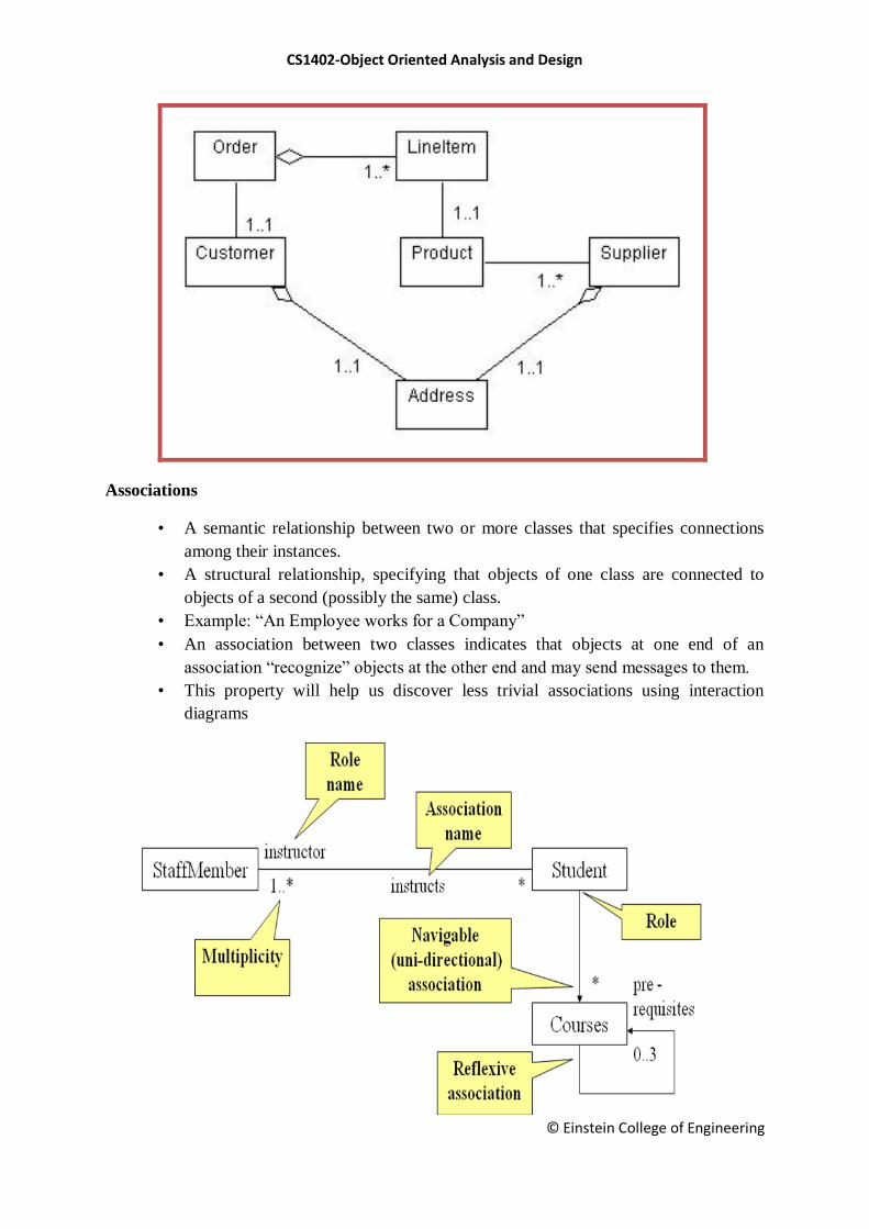
Associations
• A semantic relationship between two or more classes that specifies connections
among their instances.
• A structural relationship, specifying that objects of one class are connected to
objects of a second (possibly the same) class.
• Example: ―An Employee works for a Company‖
• An association between two classes indicates that objects at one end of an
association ―recognize‖ objects at the other end and may send messages to them.
• This property will help us discover less trivial associations using interaction
diagrams
CS1402-Object Oriented Analysis and Design
© Einstein College of Engineering
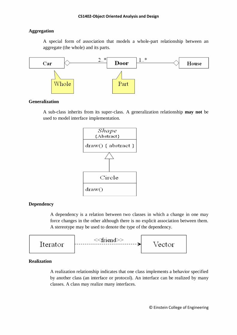
Aggregation
A special form of association that models a whole-part relationship between an
aggregate (the whole) and its parts.
Generalization
A sub-class inherits from its super-class. A generalization relationship may not be
used to model interface implementation.
Dependency
A dependency is a relation between two classes in which a change in one may
force changes in the other although there is no explicit association between them.
A stereotype may be used to denote the type of the dependency.
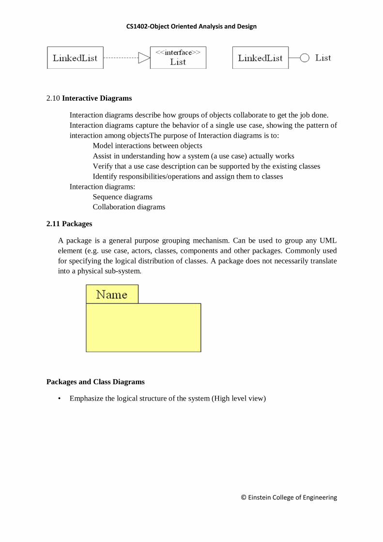
Realization
A realization relationship indicates that one class implements a behavior specified
by another class (an interface or protocol). An interface can be realized by many
classes. A class may realize many interfaces.
CS1402-Object Oriented Analysis and Design
© Einstein College of Engineering
2.10 Interactive Diagrams
Interaction diagrams describe how groups of objects collaborate to get the job done.
Interaction diagrams capture the behavior of a single use case, showing the pattern of
interaction among objectsThe purpose of Interaction diagrams is to:
Model interactions between objects
Assist in understanding how a system (a use case) actually works
Verify that a use case description can be supported by the existing classes
Identify responsibilities/operations and assign them to classes
Interaction diagrams:
Sequence diagrams
Collaboration diagrams
2.11 Packages
A package is a general purpose grouping mechanism. Can be used to group any UML
element (e.g. use case, actors, classes, components and other packages. Commonly used
for specifying the logical distribution of classes. A package does not necessarily translate
into a physical sub-system.
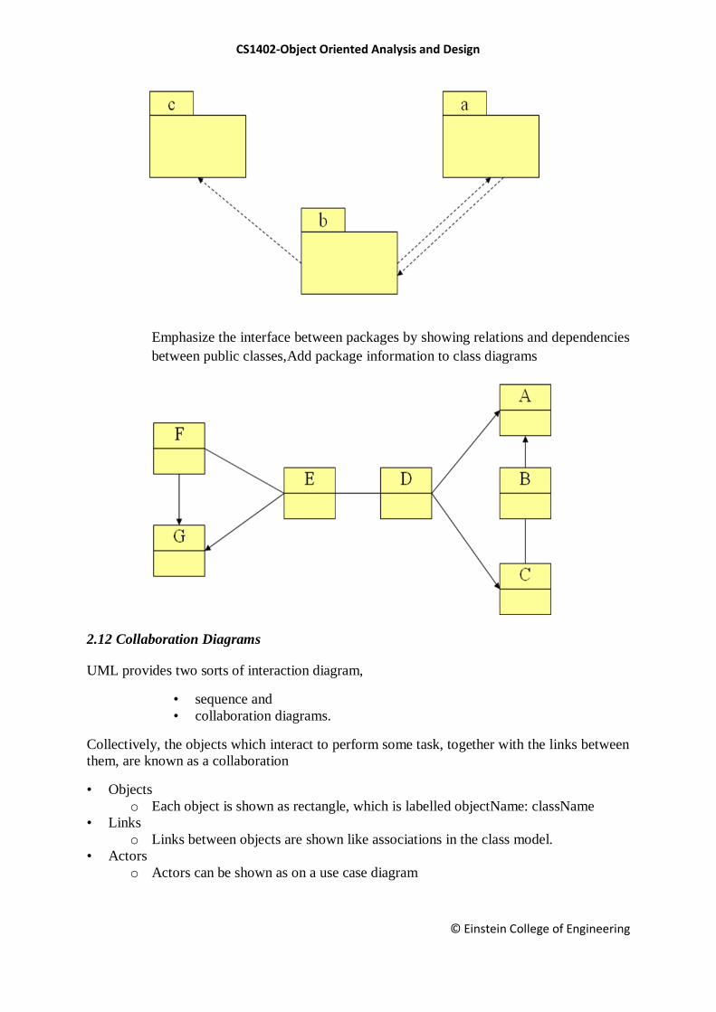
Packages and Class Diagrams
• Emphasize the logical structure of the system (High level view)
CS1402-Object Oriented Analysis and Design
© Einstein College of Engineering
Emphasize the interface between packages by showing relations and dependencies
between public classes,Add package information to class diagrams
2.12 Collaboration Diagrams
UML provides two sorts of interaction diagram,
• sequence and
• collaboration diagrams.
Collectively, the objects which interact to perform some task, together with the links between
them, are known as a collaboration
• Objects
o Each object is shown as rectangle, which is labelled objectName: className
• Links
o Links between objects are shown like associations in the class model.
• Actors
o Actors can be shown as on a use case diagram
CS1402-Object Oriented Analysis and Design
© Einstein College of Engineering
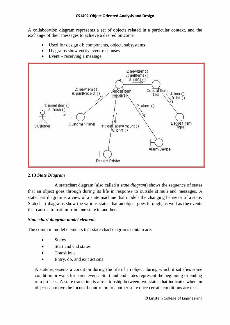
A collaboration diagram represents a set of objects related in a particular context, and the
exchange of their messages to achieve a desired outcome.
Used for design of: components, object, subsystems
Diagrams show entity event responses
Event receiving a message
2.13 State Diagram
A statechart diagram (also called a state diagram) shows the sequence of states
that an object goes through during its life in response to outside stimuli and messages. A
statechart diagram is a view of a state machine that models the changing behavior of a state.
Statechart diagrams show the various states that an object goes through, as well as the events
that cause a transition from one state to another.
State chart diagram model elements
The common model elements that state chart diagrams contain are:
States
Start and end states
Transitions
Entry, do, and exit actions
A state represents a condition during the life of an object during which it satisfies some
condition or waits for some event. Start and end states represent the beginning or ending
of a process. A state transition is a relationship between two states that indicates when an
object can move the focus of control on to another state once certain conditions are met.
CS1402-Object Oriented Analysis and Design
© Einstein College of Engineering
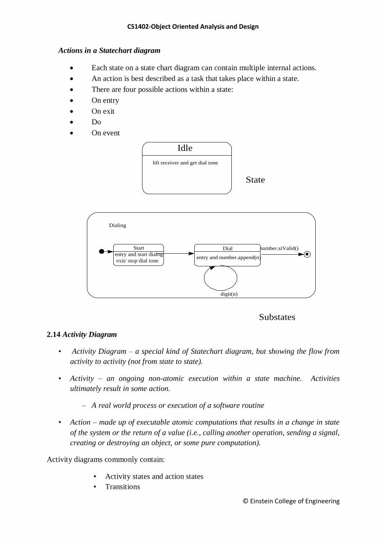
Actions in a Statechart diagram
Each state on a state chart diagram can contain multiple internal actions.
An action is best described as a task that takes place within a state.
There are four possible actions within a state:
On entry
On exit
Do
On event
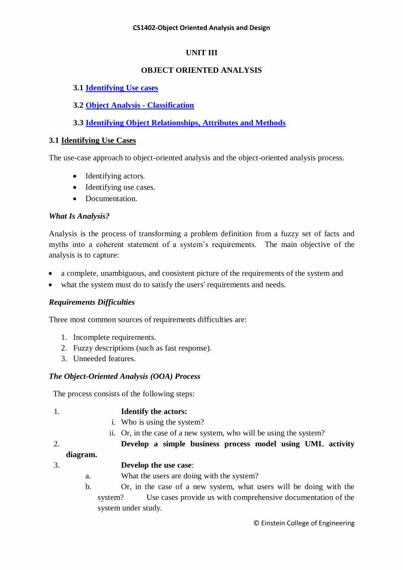
2.14 Activity Diagram
• Activity Diagram – a special kind of Statechart diagram, but showing the flow from
activity to activity (not from state to state).
• Activity – an ongoing non-atomic execution within a state machine. Activities
ultimately result in some action.
– A real world process or execution of a software routine
• Action – made up of executable atomic computations that results in a change in state
of the system or the return of a value (i.e., calling another operation, sending a signal,
creating or destroying an object, or some pure computation).
Activity diagrams commonly contain:
• Activity states and action states
• Transitions
Idle
lift receiver and get dial tone
State
Substates
Dialing
Start Dialentry and start dialog
exit/ stop dial toneentry and number.append(n)
digit(n)
number.siValid()

CS1402-Object Oriented Analysis and Design
© Einstein College of Engineering
• Objects
Action states - executable, atomic computations (states of the system, each representing the
execution of an action) – cannot be decomposed. Activity states – non-atomic; can be further
decomposed; can be represented by other activity diagrams – a composite whose flow of
control is made up of other activity states and action states

CS1402-Object Oriented Analysis and Design
© Einstein College of Engineering
Deployment Diagram
Shows the configuration of run-time processing elements and the software processes living
on them. The deployment diagram visualizes the distribution of components across the
enterprise
CS1402-Object Oriented Analysis and Design
© Einstein College of Engineering
UNIT III
OBJECT ORIENTED ANALYSIS
3.1 Identifying Use cases
3.2 Object Analysis - Classification
3.3 Identifying Object Relationships, Attributes and Methods
3.1 Identifying Use Cases
The use-case approach to object-oriented analysis and the object-oriented analysis process.
Identifying actors.
Identifying use cases.
Documentation.
What Is Analysis?
Analysis is the process of transforming a problem definition from a fuzzy set of facts and
myths into a coherent statement of a system‘s requirements. The main objective of the
analysis is to capture:
a complete, unambiguous, and consistent picture of the requirements of the system and
what the system must do to satisfy the users' requirements and needs.
Requirements Difficulties
Three most common sources of requirements difficulties are:
1. Incomplete requirements.
2. Fuzzy descriptions (such as fast response).
3. Unneeded features.
The Object-Oriented Analysis (OOA) Process
The process consists of the following steps:
1. Identify the actors:
i. Who is using the system?
ii. Or, in the case of a new system, who will be using the system?
2. Develop a simple business process model using UML activity
diagram.
3. Develop the use case:
a. What the users are doing with the system?
b. Or, in the case of a new system, what users will be doing with the
system? Use cases provide us with comprehensive documentation of the
system under study.

CS1402-Object Oriented Analysis and Design
© Einstein College of Engineering
4. Prepare interaction diagrams:
• Determine the sequence.
• Develop collaboration diagrams
5. Classification—develop a static UML class diagram:
• Identify classes.
• Identify relationships.
• Identify attributes.
• Identify methods.
6. Iterate and refine: If needed, repeat the preceding steps.
Developing Business Processes Modeling
Developing an activity diagram of the business processes can provide us with an
overall view of the system.
Use Case Model
Use cases are scenarios for understanding system requirements. The use-case model
describes the uses of the system and shows the courses of events that can be performed. Use
case defines what happens in the system when a use case is performed. The use-case model
tries to systematically identify uses of the system and therefore the system's responsibilities.
Use Cases Under the Microscope:
Refineanditerate
Identify Actors
Develop Use-Cases, ADs
DevelopInteractionDiagrams
Identify Classes,Relationships,Attributes &Methods
O-O Analysis
prototyping
CS1402-Object Oriented Analysis and Design
© Einstein College of Engineering
"A Use Case is a sequence of transactions in a system whose task is to yield results
of measurable value to an individual actor of the system."
Use Case Key Concepts
• Use case. Use case is a special flow of events through the system.
• Actors. An actor is a user playing a role with respect to the system.
• In a system. This simply means that the actors communicate with the system's use case.
• A measurable value. A use case must help the actor to perform a task that has some
identifiable value.
• Transaction. A transaction is an atomic set of activities that are performed either fully or
not at all.
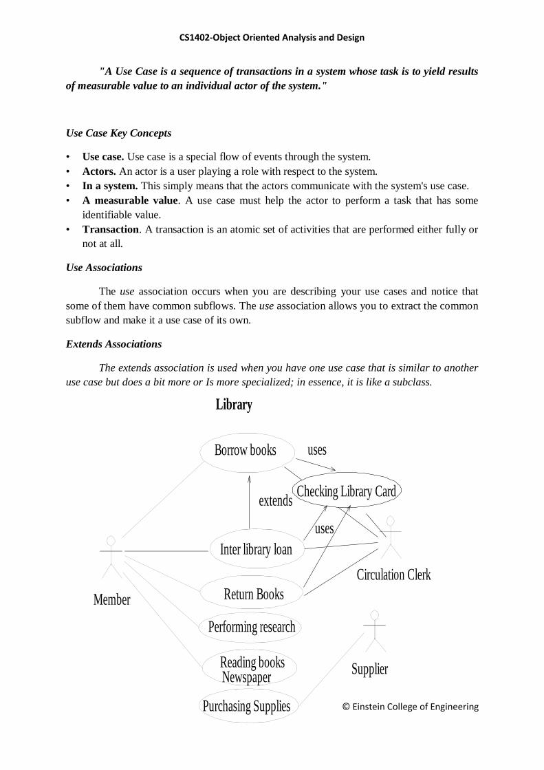
Use Associations
The use association occurs when you are describing your use cases and notice that
some of them have common subflows. The use association allows you to extract the common
subflow and make it a use case of its own.
Extends Associations
The extends association is used when you have one use case that is similar to another
use case but does a bit more or Is more specialized; in essence, it is like a subclass.
Library
Borrow books
Reading booksNewspaper
Member
Supplier
Purchasing Supplies
Inter library loan
extends
uses
uses
Performing research
Return Books
Circulation Clerk
Checking Library Card
CS1402-Object Oriented Analysis and Design
© Einstein College of Engineering
Types of Use Cases
• Use cases could be viewed as concrete or abstract.
• An abstract use case is not complete and has no initiation actors but is used by a
concrete use case, which does interact with actors.
Identifying the Actors
i. The term actor represents the role a user plays with
respect to the system.
ii. When dealing with actors, it is important to
think about roles rather than people or job titles.
iii. Who affects the system? Or,
iv. Which user groups are needed by the system to
perform its functions? These functions can be both main functions and secondary
functions, such as administration.
v. Which external hardware or other systems (if any)
use the system to perform tasks?
vi. What problems does this application solve (that is,
for whom)?
vii. And, finally, how do users use the system (use
case)? What are they doing with the system?
Guidelines for Finding Use Cases
• For each actor, find the tasks and functions that the actor should be able to perform or
that the system needs the actor to perform.
• Name the use cases.
• Describe the use cases briefly by applying terms with which the user is familiar.
Separate Actors From Users
• Each use case should have only one main actor.
• Isolate users from actors.
• Isolate actors from other actors (separate the responsibilities of each actor).
• Isolate use cases that have different initiating actors and slightly different behavior.
Documentation
An effective document can serve as a communication vehicle among the project's team
members, or it can serve as initial understanding of the requirements.
Effective Documentation: Common Cover
All documents should share a common cover sheet that identifies the document, the
current version, and the individual responsible for the content
CS1402-Object Oriented Analysis and Design
© Einstein College of Engineering
80–20 Rule
• 80 percent of the work can be done with 20 percent of the documentation.
• The trick is to make sure that the 20 percent is easily accessible and the rest (80
percent) is available to those (few) who need to know.
Familiar Vocabulary
• Use a vocabulary that your readers understand and are comfortable with.
• The main objective here is to communicate with readers and not impress them with
buzz words.
Make the Document as Short as Possible
• Eliminate all repetition;
• Present summaries, reviews, organization chapters in less than three pages.
• Make chapter headings task oriented so that the table of contents also could
serve as an index.
Organize the Document
• Use the rules of good organization (such as the organization's standards, college
handbooks, Strunk and White's Elements of Style, or the University of Chicago
Manual of Style) within each section.
The main objective of the analysis is to capture a complete, unambiguous, and consistent
picture of the requirements of the system. Construct several models and views of the system
to describe what the system does rather than how. Capturing use cases is one of the first
things to do in coming up with requirements. Every use case is a potential requirement. The
key in developing effective documentation is to eliminate all repetition; present summaries,
reviews, organization chapters in less than three pages. Use the 80–20 rule: 80 percent of the
work can be done with 20 percent of the documentation.
3.2 Object Analysis: Classification
The concept of classification
How to identify classes
Intelligent classification is intellectually hard work and may seem rather arbitrary. Martin
and Odell have observed in object-oriented analysis and design, that “In fact, an object can
be categorized in more than one way.”
Approaches for Identifying Classes
noun phrase approach
common class patterns approach
use-case driven approach
CS1402-Object Oriented Analysis and Design
© Einstein College of Engineering
classes, responsibilities, & collaborators (CRC)
approach
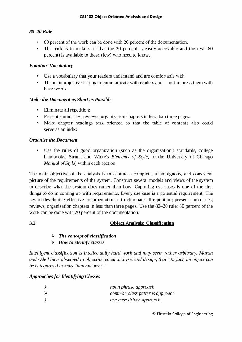
Noun Phrase Approach
It examine Use cases, conduct interviews, and read requirements specification
carefully, dividing noun phrases into three categories
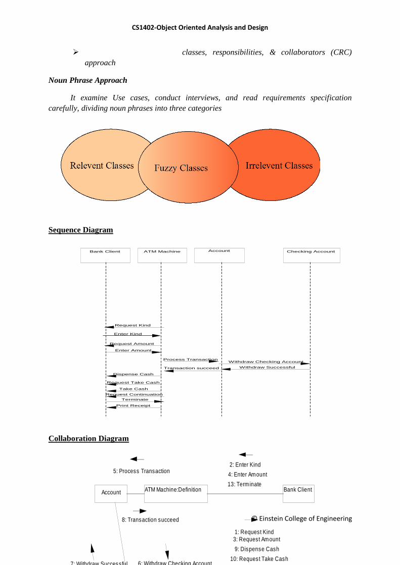
Sequence Diagram
Collaboration Diagram
Checking AccountBank Client ATM Machine Account
Withdraw Checking Account
Withdraw Successful
Request Kind
Enter Kind
Request Amount
Enter Amount
Process Transaction
Transaction succeed
Dispense Cash
Request Take Cash
Take Cash
Request Continuation
Terminate
Print Receipt
ATM Machine:Definition
Checking Account
Account Bank Client
5: Process Transaction
8: Transaction succeed
4: Enter Amount
13: Term inate
1: Request Kind
2: Enter Kind
3: Request Amount
9: Dispense Cash
10: Request Take Cash
11: Take Cash12: Request Continuation
14: Print Receipt
7: Withdraw Successful 6: Withdraw Checking Account
CS1402-Object Oriented Analysis and Design
© Einstein College of Engineering
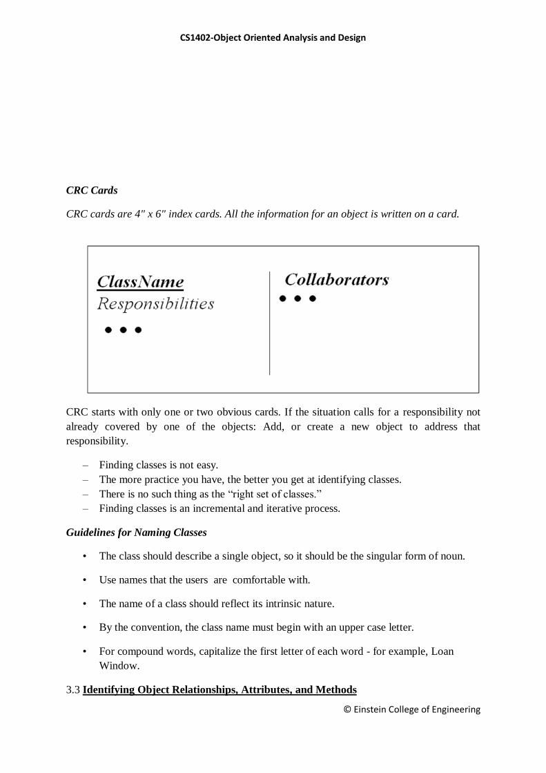
CRC Cards
CRC cards are 4" x 6" index cards. All the information for an object is written on a card.
CRC starts with only one or two obvious cards. If the situation calls for a responsibility not
already covered by one of the objects: Add, or create a new object to address that
responsibility.
– Finding classes is not easy.
– The more practice you have, the better you get at identifying classes.
– There is no such thing as the ―right set of classes.‖
– Finding classes is an incremental and iterative process.
Guidelines for Naming Classes
• The class should describe a single object, so it should be the singular form of noun.
• Use names that the users are comfortable with.
• The name of a class should reflect its intrinsic nature.
• By the convention, the class name must begin with an upper case letter.
• For compound words, capitalize the first letter of each word - for example, Loan
Window.
3.3 Identifying Object Relationships, Attributes, and Methods
CS1402-Object Oriented Analysis and Design
© Einstein College of Engineering
Goals:
– Analyzing relationships among classes
– Identifying association
– Association patterns
– Identifying super- & subclass hierarchies
Three Types of Objects Relationships
Association
Super-sub structure (also known as generalization hierarchy)
Aggregation and a-part-of structure
Guidelines for Identifying Super-sub Relationships:
Top-down
Look for noun phrases composed of various adjectives on class name.
Example, Military Aircraft and Civilian Aircraft.
Only specialize when the sub classes have significant behavior.
Bottom-up
Look for classes with similar attributes or methods.
Group them by moving the common attributes and methods to super class.
Do not force classes to fit a preconceived generalization structure.
Reusability
Move attributes and methods as high as possible in the hierarchy.
At the same time do not create very specialized classes at the top of hierarchy.
This balancing act can be achieved through several iterations.
Multiple inheritance
Avoid excessive use of multiple inheritances.
It is also more difficult to understand programs written in multiple inheritance
system.
Class Responsibility: Identifying Attributes and Methods
Identifying attributes and methods, like finding classes, is a difficult activity.
The use cases and other UML diagrams will be our guide for identifying
attributes, methods, and relationships among classes.
Identifying Class Responsibility by Analyzing Use Cases and Other UML Diagrams
Attributes can be identified by analyzing the use cases, sequence/collaboration,
activity, and state diagrams.
CS1402-Object Oriented Analysis and Design
© Einstein College of Engineering
Guidelines For Identifying Attributes Of Classes
Do not carry discovery of attributes to excess.
You can always add more attributes in the subsequent iterations.
UNIT IV
OBJECT ORIENTED DESIGN
4.1 Design axioms
4.2 Designing Classes
4.3 Access Layer
4.4 Object Storage & Object Interoperability
Designing systems using self-contained objects and object classes
To explain how a software design may be represented as a set of interacting objects that manage
their own state and operations
To describe the activities in the object-oriented design process
To introduce various models that describe an object-oriented design
To show how the UML may be used to represent these models
Characteristics of OOD
Objects are abstractions of real-world or system entities and manage themselves
Objects are independent and encapsulate state and representation information.
System functionality is expressed in terms of object services
Shared data areas are eliminated. Objects communicate by message passing
Objects may be distributed and may execute sequentially or in parallel
4.1 Design axioms
Main focus of the analysis phase of SW development ―what needs to be done‖
Objects discovered during analysis serve as the framework for design
Class‘s attributes, methods, and associations identified during analysis must be
designed for implementation as a data type expressed in the implementation language
During the design phase, we elevate the model into logical entities, some of which
might relate more to the computer domain (such as user interface, or the access layer)
CS1402-Object Oriented Analysis and Design
© Einstein College of Engineering
Refine UML class
diagrams
Refine UML class
diagrams
Apply design
axioms
than the real world or the physical domain (such as people or employees). Start
thinking how to actually implement the problem in a program.
The goal to design the classes that we need to implement the system.
Design is about producing a solution that meets the requirements that have been
specified during analysis.
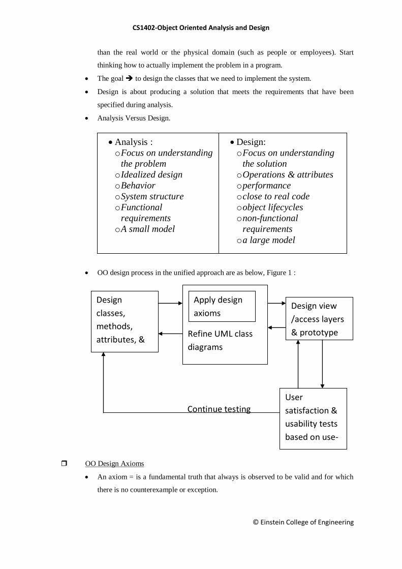
Analysis Versus Design.
OO design process in the unified approach are as below, Figure 1 :
OO Design Axioms
An axiom = is a fundamental truth that always is observed to be valid and for which
there is no counterexample or exception.
Analysis :
o Focus on understanding
the problem
o Idealized design
o Behavior
o System structure
o Functional
requirements
o A small model
Design:
o Focus on understanding
the solution
o Operations & attributes
o performance
o close to real code
o object lifecycles
o non-functional
requirements
o a large model
Continue testing
Design
classes,
methods,
attributes, &
associations
Design view
/access layers
& prototype
User
satisfaction &
usability tests
based on use-
cases
CS1402-Object Oriented Analysis and Design
© Einstein College of Engineering
A theorem = is a proposition that may not be self-evident but can be proven from
accepted axioms. Therefore, is equivalent to a law or principle.
A theorem is valid if its referent axioms & deductive steps are valid.
A corollary = is a proposition that follows from an axiom or another proposition that
has been proven
Suh‘s design axioms to OOD :
Axiom 1 : The independence axiom. Maintain the independence of
components
Axiom 2 : The information axiom. Minimize the information content of the
design.
Axiom 1 states that, during the design process, as we go from requirement and use-
case to a system component, each component must satisfy that requirement, without
affecting other requirements
Axiom 2 concerned with simplicity. Rely on a general rule known as Occam’s
razor.
Occam’s razor rule of simplicity in OO terms :
The best designs usually involve the least complex code but not necessarily the
fewest number of classes or methods. Minimizing complexity should be the goal,
because that produces the most easily maintained and enhanced application. In
an object-oriented system, the best way to minimize complexity is to use
inheritance and the system’s built-in classes and to add as little as possible to
what already is there.
Corollaries
May be called Design rules, and all are derived from the two basic axioms :
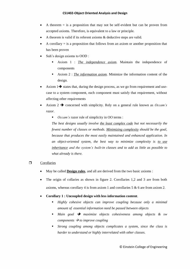
The origin of collaries as shown in figure 2. Corollaries 1,2 and 3 are from both
axioms, whereas corollary 4 is from axiom 1 and corollaries 5 & 6 are from axiom 2.
Corollary 1 : Uncoupled design with less information content.
Highly cohesive objects can improve coupling because only a minimal
amount of essential information need be passed between objects
Main goal maximize objects cohesiveness among objects & sw
components to improve coupling
Strong coupling among objects complicates a system, since the class is
harder to understand or highly interrelated with other classes.
CS1402-Object Oriented Analysis and Design
© Einstein College of Engineering
Degree or strength of coupling between two components is measured by the
amount & complexity of information transmitted between them
Figure 2 : Origin of corollaries
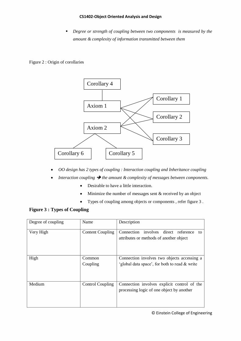
OO design has 2 types of coupling : Interaction coupling and Inheritance coupling
Interaction coupling the amount & complexity of messages between components.
Desirable to have a little interaction.
Minimize the number of messages sent & received by an object
Types of coupling among objects or components , refer figure 3 .
Figure 3 : Types of Coupling
Degree of coupling Name Description
Very High Content Coupling Connection involves direct reference to
attributes or methods of another object
High Common
Coupling
Connection involves two objects accessing a
‗global data space‘, for both to read & write
Medium Control Coupling Connection involves explicit control of the
processing logic of one object by another
Corollary 4
Axiom 1
Axiom 2
Corollary 6
Corollary 5
Corollary 3
Corollary 2
Corollary 1

CS1402-Object Oriented Analysis and Design
© Einstein College of Engineering
Low Stamp coupling Connection involves passing an aggregate
data structure to another object, which uses
only a portion of the components of the data
structure
Very low Data coupling Connection involves either simple data items
or aggregate structures all of whose elements
are used by the receving object. ( this is the
goal of an architectural design)
Inheritance coupling coupling between super-and subclasses
A subclass is coupled to its superclass in terms of attributes &
methods
High inheritance coupling is desirable
Each specialization class should not inherit lots of unrelated &
unneeded methods & attributes
Need to consider interaction within a single object or sw component Cohesion
Cohesion reflects the‘single-purposeness‘ of an object ( see
corollaries 2 & 3 )
Method cohesion a method should carry only one function.
A method carries multiple functions is undesirable
Corollary 2 : Single purpose.
Each class must have a purpose & clearly defined
Each method must provide only one service
Corollary 3 : Large number of simple classes.
Keeping the classes simple allows reusability
A class that easily can be understood and reused (or inherited) contributes to
the overall system
Complex & poorly designed class usually cannot be reused
Guideline The smaller are your classes, the better are your chances of
reusing them in other projects. Large & complex classes are too specialized
to be reused
The emphasis OOD places on encapsulation, modularization, and
polymorphism suggests reuse rather than building anew
Primary benefit of sw reusability Higher prpductivity
CS1402-Object Oriented Analysis and Design
© Einstein College of Engineering
Corollary 4 : Strong mapping.
There must be a strong association between the analysis’s object and
design’s object
OOA and OOD are based on the same model
As the model progresses from analysis to implementation, more detailed is
added
Corollary 5 : Standardization.
Promote standardization by designing interchangeable components and
reusing existing classes or components
The concept of design patterns might provide a way to capture the design
knowledge, document it, and store it in a repository that can be shared and
reused in different applications
Corollary 6 : Design with inheritance.
Common behavior (methods) must be moved to superclasses.
The superclass-subclass structure must make logical sense
Design Patterns
Provides a scheme for refining the subsystems or components of a sw system or the
relationships among them
Are devices that allow systems to share knowledge about their design, by describing
commonly recurring structures of communicating components that solve a general
design problem within a particular context
The main idea to provide documentation to help categorize & communicate about
solutions to recurring problems
The pattern has a name to facilitate discussion and the information it represents
4.2 Designing classes:
Objectives To explain how a software design may be represented as a set of interacting
objects that manage their own state and operations To describe the activities in the object-oriented
design process To introduce various models that describe an object-oriented design To show how the
UML may be used to represent these models
Characteristics of OOD :
Characteristics of OOD Objects are abstractions of real-world or system entities and
manage themselves Objects are independent and encapsulate state and representation
information.
System functionality is expressed in terms of object services Shared data areas are
eliminated.
Objects communicate by message passing Objects may be distributed and may
execute sequentially or in parallel
CS1402-Object Oriented Analysis and Design
© Einstein College of Engineering
Advantages of OOD :
Advantages of OOD Easier maintenance.
Objects may be understood as stand-alone entities Objects are appropriate reusable
components For some systems, there may be an obvious mapping from real world
entities to system objects
Object-oriented development :
Object-oriented development Object-oriented analysis, design and programming are related
but distinct OOA is concerned with developing an object model of the application domain OOD is
concerned with developing an object-oriented system model to implement requirements OOP is
concerned with realising an OOD using an OO programming language such as Java or C++
Objects and object classes :
Objects and object classes Objects are entities in a software system which represent instances of real-
world and system entities Object classes are templates for objects. They may be used to create objects
Object classes may inherit attributes and services from other object classes
Objects :
Objects An object is an entity which has a state and a defined set of operations which operate
on that state. The state is represented as a set of object attributes. The operations associated with the
object provide services to other objects (clients) which request these services when some computation
is required. Objects are created according to some object class definition. An object class definition
serves as a template for objects. It includes declarations of all the attributes and services which should
be associated with an object of that class.
The Unified Modeling Language :
The Unified Modeling Language Several different notations for describing object-oriented
designs were proposed in the 1980s and 1990s The Unified Modeling Language is an integration of
these notations It describes notations for a number of different models that may be produced during
OO analysis and design It is now a de facto standard for OO modelling
Object communication :
Object communication Conceptually, objects communicate by message passing. Messages
The name of the service requested by the calling object. Copies of the information required to execute
the service and the name of a holder for the result of the service. In practice, messages are often
implemented by procedure calls Name = procedure name. Information = parameter list.
Message examples :
Message examples // Call a method associated with a buffer
// object that returns the next value
// in the buffer
v = circularBuffer.Get () ;
// Call the method associated with a
// thermostat object that sets the
// temperature to be maintained

CS1402-Object Oriented Analysis and Design
© Einstein College of Engineering
thermostat.setTemp (20) ;
Generalisation and inheritance :
Generalisation and inheritance Objects are members of classes which define attribute types
and operations Classes may be arranged in a class hierarchy where one class (a super-class) is a
generalisation of one or more other classes (sub-classes) A sub-class inherits the attributes and
operations from its super class and may add new methods or attributes of its own Generalisation in the
UML is implemented as inheritance in OO programming languages
Advantages of inheritance :
Advantages of inheritance It is an abstraction mechanism which may be used to classify
entities It is a reuse mechanism at both the design and the programming level The inheritance graph is
a source of organizational knowledge about domains and systems
Problems with inheritance :
Problems with inheritance Object classes are not self-contained. they cannot be understood
without reference to their super-classes Designers have a tendency to reuse the inheritance graph
created during analysis. Can lead to significant inefficiency The inheritance graphs of analysis, design
and implementation have different functions and should be separately maintained
Inheritance and OOD :
Inheritance and OOD There are differing views as to whether inheritance is fundamental to
OOD. View 1. Identifying the inheritance hierarchy or network is a fundamental part of object-
oriented design. Obviously this can only be implemented using an OOPL. View 2. Inheritance is a
useful implementation concept which allows reuse of attribute and operation definitions. Identifying
an inheritance hierarchy at the design stage places unnecessary restrictions on the implementation
Inheritance introduces complexity and this is undesirable, especially in critical systems
UML associations :
UML associations Objects and object classes participate in relationships with other objects
and object classes In the UML, a generalised relationship is indicated by an association Associations
may be annotated with information that describes the association Associations are general but may
indicate that an attribute of an object is an associated object or that a method relies on an associated
object
Concurrent objects :
Concurrent objects The nature of objects as self-contained entities make them suitable for
concurrent implementation The message-passing model of object communication can be implemented
directly if objects are running on separate processors in a distributed system
Servers and active objects :
Servers and active objects Servers. The object is implemented as a parallel process (server)
with entry points corresponding to object operations. If no calls are made to it, the object suspends
itself and waits for further requests for service Active objects Objects are implemented as parallel
processes and the internal object state may be changed by the object itself and not simply by external
calls

CS1402-Object Oriented Analysis and Design
© Einstein College of Engineering
Active transponder object :
Active transponder object Active objects may have their attributes modified by operations but
may also update them autonomously using internal operations Transponder object broadcasts an
aircraft‘s position. The position may be updated using a satellite positioning system. The object
periodically update the position by triangulation from satellites
Java threads :
Java threads Threads in Java are a simple construct for implementing concurrent objects
Threads must include a method called run() and this is started up by the Java run-time system Active
objects typically include an infinite loop so that they are always carrying out the computation
An object-oriented design process :
An object-oriented design process Define the context and modes of use of the system Design
the system architecture Identify the principal system objects Develop design models Specify object
interfaces
Architectural design :
Architectural design Once interactions between the system and its environment have been
understood, you use this information for designing the system architecture Layered architecture is
appropriate for the weather station Interface layer for handling communications Data collection layer
for managing instruments Instruments layer for collecting data There should be no more than 7
entities in an architectural model
Object identification :
Object identification Identifying objects (or object classes) is the most difficult part of object
oriented design There is no 'magic formula' for object identification. It relies on the skill, experience
and domain knowledge of system designers Object identification is an iterative process. You are
unlikely to get it right first time
Approaches to identification :
Approaches to identification Use a grammatical approach based on a natural language
description of the system (used in Hood method) Base the identification on tangible things in the
application domain Use a behavioural approach and identify objects based on what participates in
what behaviour Use a scenario-based analysis. The objects, attributes and methods in each scenario
are identified
Weather station object classes :
Weather station object classes Ground thermometer, Anemometer, Barometer Application
domain objects that are ‗hardware‘ objects related to the instruments in the system Weather station
The basic interface of the weather station to its environment. It therefore reflects the interactions
identified in the use-case model Weather data Encapsulates the summarised data from the instruments
Further objects and object refinement :
Further objects and object refinement Use domain knowledge to identify more objects and
operations Weather stations should have a unique identifier Weather stations are remotely situated so
instrument failures have to be reported automatically. Therefore attributes and operations for self-
checking are required Active or passive objects In this case, objects are passive and collect data on
CS1402-Object Oriented Analysis and Design
© Einstein College of Engineering
request rather than autonomously. This introduces flexibility at the expense of controller processing
time
Design models :
Design models Design models show the objects and object classes and relationships between
these entities Static models describe the static structure of the system in terms of object classes and
relationships Dynamic models describe the dynamic interactions between objects.
Examples of design models :
Examples of design models Sub-system models that show logical groupings of objects into
coherent subsystems Sequence models that show the sequence of object interactions State machine
models that show how individual objects change their state in response to events Other models
include use-case models, aggregation models, generalisation models,etc.
Subsystem models :
Subsystem models Shows how the design is organised into logically related groups of objects
In the UML, these are shown using packages - an encapsulation construct. This is a logical model.
The actual organisation of objects in the system may be different.
Sequence models :
Sequence models Sequence models show the sequence of object interactions that take place
Objects are arranged horizontally across the top Time is represented vertically so models are read top
to bottom Interactions are represented by labelled arrows, Different styles of arrow represent different
types of interaction A thin rectangle in an object lifeline represents the time when the object is the
controlling object in the system
Statecharts :
Statecharts Show how objects respond to different service requests and the state transitions
triggered by these requests If object state is Shutdown then it responds to a Startup() message In the
waiting state the object is waiting for further messages If reportWeather () then system moves to
summarising state If calibrate () the system moves to a calibrating state A collecting state is entered
when a clock signal is received
Object interface specification :
Object interface specification Object interfaces have to be specified so that the objects and
other components can be designed in parallel Designers should avoid designing the interface
representation but should hide this in the object itself Objects may have several interfaces which are
viewpoints on the methods provided The UML uses class diagrams for interface specification but Java
may also be used
Design evolution :
Design evolution Hiding information inside objects means that changes made to an object do
not affect other objects in an unpredictable way Assume pollution monitoring facilities are to be
added to weather stations. These sample the air and compute the amount of different pollutants in the
atmosphere Pollution readings are transmitted with weather data
4.3 Access Layer
The main idea behind creating an access layer is to create a set of classes that know how to
communicate with the place(s) where the data actually reside. Regardless of where the data reside,
CS1402-Object Oriented Analysis and Design
© Einstein College of Engineering
whether it be a file, relational database, mainframe, Internet, DCOM or via ORB, the access classes
must be able to translate any data-related requests from the business layer into the appropriate
protocol for data access. These classes also must be able to translate the data retrieved back into the
appropriate business objects. The access layer‘s main responsibility is to provide a link between
business or view objects and data storage. Three-layer architecture is similar to 3-tier architecture.
The view layer corresponds to the client tier, the business layer to the application server tier and the
access layer performs two major tasks:
Translate the request: The access layer must be able to translate any data related requests from the
business layer into the appropriate protocol for data access.
•Translate the results: The access layer also must be able to translate the data retrieved back into the
appropriate business objects and pass those objects back into the business layer.
•Here design is tied to any base engine or distributed object technology such as CORBA or DCOM.
Here we can switch easily from one database to another with no major changes to the user interface or
business layer objects. All we need to change are the access classes‘ methods.
A Date Base Management System (DBMS) is a set of programs that enables the creation and
maintenance (access, manipulate, protect and manage) of a collection of related data.
• The purpose of DBMS is to provide reliable, persistent data storage and mechanisms for
efficient, convenient data access and retrieval.
• Persistence refers to the ability of some objects to outlive the programs that created them.
• Object lifetimes can be short for local objects (called transient objects) or long for objects
stored indefinitely in a database (called persistent objects).
Most object-oriented languages do not support serialization or object persistence, which is the process
of writing or reading an object to and from a persistence storage medium, such as disk file.
• Unlike object oriented DBMS systems, the persistent object stores do not support query or
interactive user interface facilities.
• Controlling concurrent access by users, providing ad-hoc query capability and allowing
independent control over the physical location of data are not possible with persistent objects.
• The access layer (AL), which is a key part of every n-tier system, is mainly consist of a simple set of
code that does basic interactions with the database or any other storage device. These functionalities
are often referred to as CRUD (Create, Retrieve, Update, and Delete).
• The data access layer need to be generic, simple, quick and efficient as much as possible. It should not
include complex application/ business logics.
• I have seen systems with lengthy, complex store procedures (SP), which run through several cases
before doing a simple retrieval. They contain not only most part of the business logic, but application
logic and user interface logic as well. If SP is getting longer and complicated, then it is a good
indication that you are burring your business logic inside the data access layer.
4.4 Object Storage & Object Interoperability
CS1402-Object Oriented Analysis and Design
© Einstein College of Engineering
Atkinson describe 6 broad categories for the lifetime of a data.
•Transient results to the evaluation of expressions Variables involved in procedure activation
•Global variables and variables that are dynamically allocated
•Data that exist between the execution of a program
•Data that exist between the versions of a program
•Data that outlive a program.
•The first 3 are transient data, data that cease to exist beyond the lifetime of the creating process. The
other 3 are non transient, or persistent data.
•The programming languages provide excellent support for transient data. The non-transient data are
well
supported by DBMS or a file system. In traditional file processing, each application defines and
implements the files it requires.
• In DBMS, a single repository of data is maintained, which can be defined once and subsequently
accessed
by various users.
• DBMS contains not only the data but a a complete definition of the data formats it manages, known as
Schema or Meta-data, which contains a complete definition of the data formats, such as the data
structures, types and constraints.
• In file processing applications, such meta data are encapsulated in the application programs
themselves.
But in DBMS, the format of the meta-data is independent of any particular application data structure.
Common Object Request Broker Architecture
It is used to integrate distributed, heterogeneous business applications and data. The CORBA
interface definition language (IDL) allows developers to specify language-neutral, object-
oriented interfaces for application and system components. IDL definitions are stored in an
interface repository that offers object interfaces and services. For distributed enterprise
computing, the interface repository is central to communication among objects located on
different systems.CORBA implements a communication channel through which applications can
access object interfaces and request data and services. The CORBA common object environment
(COE) provides system level services such as life cycle management for objects accessed through
CORBA, event notification between objects and transaction and concurrency control.
CS1402-Object Oriented Analysis and Design
© Einstein College of Engineering
Unit V
SOFTWARE QUALITY AND USABILITY
5.1 Designing Interface Objects
5.2 Software Quality Assurance
5.3 System Usability & Measuring User Satisfaction
5.1 Designing Interface Objects
In computing an object-oriented user interface (OOUI) is a type of user
interface based on an object-oriented programming metaphor. In an OOUI, the
user interacts explicitly with objects that represent entities in the domain that the
application is concerned with. Many vector drawing applications, for example,
have an OOUI - the objects being lines, circles and canvases. The user may
explicitly select an object, alter its properties (such as size or color), or invoke
other actions upon it (such as to move, copy, or re-align it). If a business
application has any OOUI, the user may be selecting and/or invoking actions on
objects representing entities in the business domain such as customers, products
or orders.
Jakob Nielsen defines the OOUI in contrast to function-oriented interfaces:
"Object-oriented interfaces are sometimes described as turning the application
inside-out as compared to function-oriented interfaces. The main focus of the
interaction changes to become the users' data and other information objects that
are typically represented graphically on the screen as icons or in windows‖
Dave Collins defines an OOUI as demonstrating three characteristics:
Users perceive and act on objects
Users can classify objects based on how they behave
In the context of what users are trying to do, all the user interface objects
fit together into a coherent overall representation.
Jef Raskin suggests that the most important characteristic of an OOUI is that it
adopts a 'noun-verb', rather than a 'verb-noun' style of interaction, and that this
has several advantages in terms of usability.
CS1402-Object Oriented Analysis and Design
© Einstein College of Engineering
5.2 Software Quality Assurance
• Bugs and Debugging
• Testing strategies.
• The impact of an object orientation on testing.
• How to develop test cases.
• How to develop test plans.
Introduction
Two issues in software quality are:
• Validation or user satisfaction
• Verification or quality assurance.
• Elimination of the syntactical bug is the process of debugging.
• Detection and elimination of the logical bug is the process of testing.
• Error Types:
• Language errors or syntax errors
• Run-time errors
• Logic errors
Identifying Bugs and Debugging
• The first step in debugging is recognizing that a bug exists.
• Sometimes it's obvious; the first time you run the application, it shows
itself.
• Other bugs might not surface until a method receives a certain value, or
until you take a closer look at the output
There are no magic tricks for debugging.
However, these steps might help:
• Selecting appropriate testing strategies.
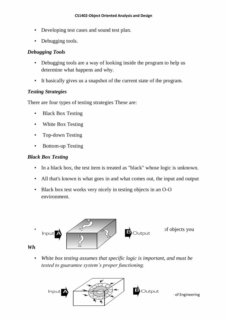
CS1402-Object Oriented Analysis and Design
© Einstein College of Engineering
• Developing test cases and sound test plan.
• Debugging tools.
Debugging Tools
• Debugging tools are a way of looking inside the program to help us
determine what happens and why.
• It basically gives us a snapshot of the current state of the program.
Testing Strategies
There are four types of testing strategies These are:
• Black Box Testing
• White Box Testing
• Top-down Testing
• Bottom-up Testing
Black Box Testing
• In a black box, the test item is treated as "black" whose logic is unknown.
• All that's known is what goes in and what comes out, the input and output
• Black box test works very nicely in testing objects in an O-O
environment.
• Once you have created fully tested and debugged classes of objects you
will put them into library for use or reuse.
White Box Testing
• White box testing assumes that specific logic is important, and must be
tested to guarantee system’s proper functioning.
Input Output
Input Output
CS1402-Object Oriented Analysis and Design
© Einstein College of Engineering
• One form of white box testing is called path testing.
• It makes certain that each path in a program is executed at least once
during testing.
Two types of path testing are:
• Statement testing coverage, and
• Branch testing coverage
Top-down Testing
It assumes that the main logic of the application needs more testing than
supporting logic.
Bottom-up Approach
• It takes an opposite approach.
• It assumes that individual programs and modules are fully developed as
standalone processes.
• These modules are tested individually, and then combined for integration
testing.
5.3 System Usability & Measuring User Satisfaction
• Verification - "Am I building the product right?"
• Validation - "Am I building the right product?"
• Two main issues in software quality are validation or user satisfaction
and verification or quality assurance.
• The process of designing view layer classes consists of the following
steps:
1. In the macro-level user interface (UI) design process, identify view layer
objects.
CS1402-Object Oriented Analysis and Design
© Einstein College of Engineering
2. In the micro-level UI, apply design rules and GUI guidelines.
3. Test usability and user satisfaction.
4. Refine and iterate the design.
Usability and User Satisfaction Testing
Two issues will be discussed:
1. Usability Testing and how to develop a plan for usability testing.
2. User Satisfaction Test and guidelines for developing a plan for user
satisfaction testing.
• The International Organization for Standardization (ISO) defines
usability as the effectiveness, efficiency, and satisfaction with which a
specified set of users can achieve a specified set of tasks in
particular environments.
• Defining tasks. What are the tasks?
• Defining users. Who are the users?
• A means for measuring effectiveness, efficiency, and satisfaction.
• The phrase two sides of the same coin is helpful for describing the
relationship between the usability and functionality of a system.
• Usability testing measures the ease of use as well as the degree of
comfort and satisfaction users have with the software.
• Usability testing must begin with defining the target audience and test
goals.
• Run a pilot test to work out the bugs of the tasks to be tested.
• Make certain the task scenarios, prototype, and test equipment work
smoothly.
Guidelines for Developing Usability Testing
• ―Focus groups" are helpful for generating initial ideas or trying out new
ideas.
CS1402-Object Oriented Analysis and Design
© Einstein College of Engineering
• It requires a moderator who directs the discussion about aspects of a task
or design.
• Apply usability testing early and often.
• Include all of software‘s components in the test.
The testing doesn‘t need to be very expensive, a tape recorder, stopwatch,
notepad and an office can produce excellent results.
• Tests need not involve many subjects.
• More typically, quick, iterative tests with a small, well-targeted sample of
6 to 10 participants can identify 80–90 percent of most design
problems.
• Focus on tasks, not features.
• Remember that your customers will use features within the context of
particular tasks.
• Make participants feel comfortable by explaining the testing process.
• Emphasize that you are testing the software, not the participants.
• If they become confused or frustrated, it is not a reflection on them.
• Do not interrupt participants during a test.
• If they need help, begin with general hints before moving to specific
advice.
• Keep in mind that less intervention usually yields better results.
• Record the test results using a portable tape recorder, or better, a video
camera.
• You may also want to follow up the session with the user satisfaction
test.
• The test is inexpensive, easy to use and it is educational to those who
administer it and those who fill it out.
Even if the results may never be summarized, or filled out, the process of
creating the test itself will provide us with useful information.