
Crystal River 3 Initial Exam 2009-301 Final Simulator Scenarios. · • TS 3.5.2, Condition A, for...
124
Appendix D Scenario Outline Form ES-D-I Facility: Crystal River #3 Scenario No.: #1 (NRC 2009) Op-TestNo.: 1 Examiners: Operators: Initial Conditions: The plant is at approximately 30% power. Turnover: The following equipment is OOS: DHP-1A (12 hours); MUP-1A (12 hours); RWP-1 (24 hours); FWP-7 (32 hours). An emergency need for power exists. Event Malf. Event Event No. No. Type * Description 1 N/A R(RO) Manual power escalation. (OP-204) 2 1 C (RO or BOP) FW-223/224-TE trend up. Requires startup ofFWP-1B and shutdown ofFWP-IA. (OP-60S) 3 2 C (BOP) OPT major alarm. (OP-703) C (SRO) SRO TS determination. (TS 3.8.1) 4 N/A N (BOP) Perform SP-32I, Page 1 of Enclosure 1. (SP-32I) S 3 I (BOP) RM-ASG fails high. (AP-2S0) 6 4 I (RO) RC-I-LTl fails low. (OP-SOI) I (SRO) SRO TS determination. (TS 3.3.17 & 3.4.8) 7 S M (ALL) PZR steam space leak, RPS fails to actuate. [CT] (EOP-2) 8 6 C (RO or BOP) MUV-S86 fails closed, MUV-2S fails to open. [CT] (EOP-3, EOP-13 Rules 1, 2 & 3) 9 7 C (RO or BOP) RCP-ID breaker will not open. [CT] (AI-SOS) * (N)ormal, (R)eactivity, (I)nstrument, (C)omponent, (M)ajor Z _. I <'..18uJ5 (,r,rfeC.. \)-..1-- /?U ['MTS $; +) 5) & 8/25/2009 Page 1 of 1 9:24 AM H:\NRC - 2009\Post Prep Week\sES\2oo9 NRC - SES #l\NRC 2009 - SES #1 Scenario Outline NRC Fonn ES-D-1, FlNAL.docx Appendix D Scenario Outline Form ES-D-I Facility: Crystal River #3 Scenario No.: #1 (NRC 2009) Op-TestNo.: 1 Examiners: Operators: Initial Conditions: The plant is at approximately 30% power. Turnover: The following equipment is OOS: DHP-1A (12 hours); MUP-1A (12 hours); RWP-1 (24 hours); FWP-7 (32 hours). An emergency need for power exists. Event Malf. Event Event No. No. Type * Description 1 N/A R(RO) Manual power escalation. (OP-204) 2 1 C (RO or BOP) FW-223/224-TE trend up. Requires startup ofFWP-1B and shutdown ofFWP-IA. (OP-60S) 3 2 C (BOP) OPT major alarm. (OP-703) C (SRO) SRO TS determination. (TS 3.8.1) 4 N/A N (BOP) Perform SP-32I, Page 1 of Enclosure 1. (SP-32I) S 3 I (BOP) RM-ASG fails high. (AP-2S0) 6 4 I (RO) RC-I-LTl fails low. (OP-SOI) I (SRO) SRO TS determination. (TS 3.3.17 & 3.4.8) 7 S M (ALL) PZR steam space leak, RPS fails to actuate. [CT] (EOP-2) 8 6 C (RO or BOP) MUV-S86 fails closed, MUV-2S fails to open. [CT] (EOP-3, EOP-13 Rules 1, 2 & 3) 9 7 C (RO or BOP) RCP-ID breaker will not open. [CT] (AI-SOS) * (N)ormal, (R)eactivity, (I)nstrument, (C)omponent, (M)ajor Z _. I <'..18uJ5 (,r,rfeC.. \)-..1-- /?U ['MTS $; +) 5) & 8/25/2009 Page 1 of 1 9:24 AM H:\NRC - 2009\Post Prep Week\sES\2oo9 NRC - SES #l\NRC 2009 - SES #1 Scenario Outline NRC Fonn ES-D-1, FlNAL.docx
Transcript of Crystal River 3 Initial Exam 2009-301 Final Simulator Scenarios. · • TS 3.5.2, Condition A, for...

Appendix D Scenario Outline Form ES-D-I
Facility: Crystal River #3 Scenario No.: #1 (NRC 2009) Op-TestNo.: 1
Examiners: Operators:
Initial Conditions: The plant is at approximately 30% power.
Turnover: The following equipment is OOS: DHP-1A (12 hours); MUP-1A (12 hours); RWP-1 (24 hours); FWP-7 (32 hours). An emergency need for power exists.
Event Malf. Event Event No. No. Type * Description
1 N/A R(RO) Manual power escalation. (OP-204)
2 1 C (RO or BOP) FW-223/224-TE trend up. Requires startup ofFWP-1B and shutdown ofFWP-IA. (OP-60S)
3 2 C (BOP) OPT major alarm. (OP-703) C (SRO) SRO TS determination. (TS 3.8.1)
4 N/A N (BOP) Perform SP-32I, Page 1 of Enclosure 1. (SP-32I)
S 3 I (BOP) RM-ASG fails high. (AP-2S0)
6 4 I (RO) RC-I-LTl fails low. (OP-SOI)
I (SRO) SRO TS determination. (TS 3.3.17 & 3.4.8)
7 S M (ALL) PZR steam space leak, RPS fails to actuate. [CT] (EOP-2)
8 6 C (RO or BOP) MUV-S86 fails closed, MUV-2S fails to open. [CT] (EOP-3, EOP-13 Rules 1, 2 & 3)
9 7 C (RO or BOP) RCP-ID breaker will not open. [CT] (AI-SOS)
* (N)ormal, (R)eactivity, (I)nstrument, (C)omponent, (M)ajor
Z _. I ~
<'..18uJ5 (,r,rfeC.. \)-..1--
/?U ['MTS $; +) 5) &
8/25/2009 Page 1 of 1 9:24 AM H:\NRC - 2009\Post Prep Week\sES\2oo9 NRC - SES #l\NRC 2009 - SES #1 Scenario Outline NRC Fonn ES-D-1, FlNAL.docx

Narrative Summary NRC 2009 Scenario #1
The plant is at ",30% power following initial loading of the main generator. The OACIBOP will continue in OP-204 from step 4.1.26.
After power has risen (S to 10%) FW temperature elements on the running FWBP rise. The other booster pump should be started, the running booster pump shutdown and maintenance called to investigate.
After FWP-IA is secured an OPT major alarm will be received. The "A" ES 4160 bus will be transferred to the BEST. Two seconds after the transfer the OPT breaker will trip open. The SRO may direct the transfer from memory or may utilize OP-703, Plant Distribution System. Either way is acceptable. TS 3.8.1, Condition A, will be entered for one offsite circuit inoperable. The BOP will perform SP-321, Enclosure 1.
When SP-321 is completed RM-ASG will fail high. Entry conditions for AP-2S0, Radiation Monitor Actuation, are met. Only the monitor/meter has failed high. No automatic actions occur. The Control Complex will be isolated and CC Emergency Recirc initiated.
While the BOP is performing actions of AP-2S0 RC-I-LTI (PZR level control) transmitter will fail low. This will require the OAC to take manual control ofMUV-31 and utilize OP-SOI to select a good instrument. TS 3.3 .17 will be entered for loss of PAM instrumentation.
Following selection ofRC-I-LT3 for PZR level control a PZR steam space leak occurs. RPS will not actuate on low pressure and the OAC must manually trip the reactor reT]. The reactor trip will cause a larger leak that will lead to an ISCM event.
When HPI actuates MUV-S86 (HPI cross-tie valve) fails closed, MUV-2S will not open due to a normal source power failure. Alternate power source will be selected during the performance of EOP-3 leT]. Since MUP-IC will experience a sheared shaft on start this action is critical to ensure sufficient HPI flow to the RCS. Entry into an "Alert" is required due to the loss of SCM.
When the loss of SCM occurs RCPs must be tripped within I minute leT]. RCP-ID breaker will not open when commanded and the OACIBOP must open breaker 3104 ("B" 6900V Rx Aux Bus feeder breaker).
This scenario may be terminated when Step 3.9 in EOP-03 is completed.
8/2512009 Page 1 of 6 9:24AM H:\NRC - 2009\Post Prep WeekISES\2009 NRC - SES #IISES #1 - 2009 NRC - Summary - Turnover FINAL.docx

Procedures used: (ARs not listed)
OP-204 AP-2S0 EOP-2 OP-60S AP-S20 EOP-3 OP-SOI AI-SOS EOP-13 OP-703 EOP-14
SP-321
Target Quantitative Attributes - Scenario #1 - NRC 2009 Actual Attributes
1. Total Malfunctions (S-8) 7
2. Malfunctions after EOP entry (1-2) 2
3. Abnormal Events (2-4) 2
4. Major Transients (1-2) 1
S. EOPs entered requiring substantive actions (1-2) 2
6. EOP contingencies requiring substantive actions (0-2) 1
7. Critical Task (2-3) 3
8/25/2009 Page 2 of 6 9:24AM H:INRC - 2009\Post Prep Week\sES\2009 NRC - SES #IISES #1 - 2009 NRC - Summary - Turnover FINAL.docx

SHIFT TURNOVER
A. Initial Conditions:
1. Time in core life - 300 EFPD 2. Shift: [X] Day [] Night 3. Rx power and power history - Power escalation in progress with power at 30%. Previously
shutdown for 3 days 4. Boron concentration - 1055 PPMB 5. Xenon - See Saxon 6. RCS Activity - See Status Board 7. EOOS Condition: Yellow 8. Protected Train - B
B. Tech. Spec. Action requirement(s) in effect:
• TS 3.5.2, Condition A, for DHP-1A. Condition entered 12 hours ago. • TS 3.3.17, Condition A, Function 23, for LPI Pump Run Status lights. Condition
entered 12 hours ago.
• CP-500, FWP-7 • Fire Protection Plan, Table 6.9A, for MUP-1A
C. Clearances in effect:
• DHP-1A for breaker fuse block replacement. Expected return to service in 4 hours. • MUP-1A shaft replacement due to high vibration. Expected return to service in 24
hours. • RWP-l for impeller replacement. Expected return to service in 4 hours. • FWP-7 motor bearing replacement. Expected return to service in 12 hours.
D. Significant problems/abnormalities:
• Grid Condition is RED • An emergency need for power exists due to other generating facilities being
unavailable.
E. Evolutions/maintenance for the on-coming shift:
• Continue power escalation per OP-204 at step 4.1.26. • Dispatcher has requested power escalation as fast as possible. Reactor engineering
has approved up to a 30%lhour power escalation. • Calculations are in progress for additional RCS water additions. • Maintenance to continue work on DHP-1A, MUP-1A, RWP-l and FWP-7.
F. CRS - Instruct the ROs to walk down the main control board.
G. Required Emergency Plan Implementation
[ ] Full Implementation, including all required notifications. [ ] InitiaVupgrade classifications - internal notifications. [X] None
8/25/2009 Page 3 of 6 H:\NRC - 2009\Post Prep Week\sES\2009 NRC - SES #I\SES #1 - 2009 NRC - Summary - Turnover FINAL.docx
9:24AM

# 1 2 3 4 5 6 7
8
INITIAL CONDITIONS
Examination Setup/Execution Scenario #1
A. "Restore" the simulator to Ie # 170 developed for this SES.
B. "Unfreeze" the simulator and ensure the following configuration is setup:
1. RWP-2A running 2. Approximately 30% power 3. AULD Nozzle and LEFM quality OFF 4. AULD Alerts Acknowledged
C. "Freeze" the simulator and enter "Exam 4" lesson plan directory.
1. "Start" Lesson Plan SES #1 NRC-2009
D. "Unfreeze" the simulator and "Trigger" Setup Step(s) which will:
See Simulator lesson plan
E. Tag out the following equipment:
Component Placed Removed Place CIT on DHP-1A CIS in Normal After Stop Place CIT on MUP-1A CIS in Normal After Stop Place CIT on MUP-2A CIS in Normal After Stop Place CIT on MUP-3A CIS in Pull To Lock Place CIT on MUP-4A CIS in StClQ Place CIT on MUP-5A CIS in Stop Place CIT on RWP-l CIS in Normal After Stop Place CIT on FWP-7 CIS in Normal After Stop
F. Additional Modifications required to the IC.
1. Ensure SPDS selected to NORMIIMB and history traces cleared and history trace selected. Also ensure "A" and "B" SPDS are properly selected for RCS Loops and Primary instruments selected.
2. Ensure SPDS on CNO/SSO/ST A computers displaying correct data for IC.
3. Ensure Group 59 indicative of current reactor power.
4. Acknowledge computer and annunciator alarms.
5. Ensure proper PICS groups displayed on overhead screens with correct scaling.
6. Ensure Annunciator Log cleared and restarted.
7. Consumable copies ofOP-501, OP-504, OP-703 and SP-321.
G. Ensure copy of OP-204 available and signed off up to step 4.1.26. Ensure copy of OP-605 available with appropriate steps signed off to step 4.4.9.
8/25/2009 Page 4 of6 9:24 AM H:INRC - 2009\Post Prep Week\SES\2009 NRC - SES #1\SES #1 - 2009 NRC - Summary - Turnover FINAL.docx
# 1 2 3 4 5 6 7
8
INITIAL CONDITIONS
Examination Setup/Execution Scenario #1
A. "Restore" the simulator to Ie # 170 developed for this SES.
B. "Unfreeze" the simulator and ensure the following configuration is setup:
1. RWP-2A running 2. Approximately 30% power 3. AULD Nozzle and LEFM quality OFF 4. AULD Alerts Acknowledged
C. "Freeze" the simulator and enter "Exam 4" lesson plan directory.
1. "Start" Lesson Plan SES #1 NRC-2009
D. "Unfreeze" the simulator and "Trigger" Setup Step(s) which will:
See Simulator lesson plan
E. Tag out the following equipment:
Comj)onent Placed Removed Place CIT on DHP-1A CIS in Normal After Stop Place CIT on MUP-1A CIS in Normal After Stop Place CIT on MUP-2A CIS in Normal After Stop Place CIT on MUP-3A CIS in Pull To Lock Place CIT on MUP-4A CIS in Stop Place CIT on MUP-5A CIS in Stop Place CIT on RWP-l CIS in Normal After Stop Place CIT on FWP-7 CIS in Normal After Stop
F. Additional Modifications required to the IC.
1. Ensure SPDS selected to NORMIIMB and history traces cleared and history trace selected. Also ensure "A" and "B" SPDS are properly selected for RCS Loops and Primary instruments selected.
2. Ensure SPDS on CNO/SSO/ST A computers displaying correct data for IC.
3. Ensure Group 59 indicative of current reactor power.
4. Acknowledge computer and annunciator alarms.
5. Ensure proper PICS groups displayed on overhead screens with correct scaling.
6. Ensure Annunciator Log cleared and restarted.
7. Consumable copies ofOP-501, OP-504, OP-703 and SP-321.
G. Ensure copy of OP-204 available and signed off up to step 4.1.26. Ensure copy of OP-605 available with appropriate steps signed off to step 4.4.9.
8/25/2009 Page 4 of6 9:24 AM H:INRC - 2009\Post Prep Week\SES\2009 NRC - SES #1\SES #1 - 2009 NRC - Summary - Turnover FINAL.docx

Booth Operator Actions NRC 2009
START DATA RECORDER NRCEXAM.DRD
A. EVENT #1 - Normal Evolution - Manual power increase
B. EVENT #2 When directed insert FWP-1A temperature element malfunctions. (Trigger Step #1: FW-223/224-TE (FWP-IA) trend up slowly]
Scenario #1
Role Play: If contacted as the SPO to check FWP-1A bearing temperatures wait about 2 minutes and report that the bearings are hotter than normal and seem to be heating up further. State that oil levels are normal and you don't know why they are heating up.
Role Play: When contacted as the SPO to partially open FWV -7 wait about two minutes and notifY the control room that the valve is about 40% open. (Trigger Step #2: FWV-7 stroke to 40% open]
Remove FW-223/224-TE failures when FWP-IA is secured.
C. EVENT #3 When directed insert the OPT failure. (Trigger Step #3: OPT Major Alarm]
D. EVENT #4 - Normal Evolution - Perform SP-321
Role Play: When contacted as the System Dispatcher state that switchyard voltage is 240kv.
Role Play: When contacted as SPO to perform steps 1.9, 1.10 and 1.11 ofSP-321 wait about 2 minutes then report back completion of steps.
E. EVENT #5 When directed insert the RM-A5G failure. (Trigger Step #4: RM-A5G Fail High]
F. EVENT #6 When directed insert the PZR level transmitter failure. (Trigger Step #5: PZR Level Transmitter Fail Low]
8/25/2009 Page 5 of 6 H:INRC - 2009\Post Prep Week\SES\2009 NRC - SES #1\SES #1 - 2009 NRC - Summary - Turnover FINAL.docx
9:24AM
Booth Operator Actions NRC 2009
START DATA RECORDER NRCEXAM.DRD
A. EVENT #1 - Normal Evolution - Manual power increase
B. EVENT #2 When directed insert FWP-1A temperature element malfunctions. (Trigger Step #1: FW-223/224-TE (FWP-IA) trend up slowly)
Scenario #1
Role Play: If contacted as the SPO to check FWP-1A bearing temperatures wait about 2 minutes and report that the bearings are hotter than normal and seem to be heating up further. State that oil levels are normal and you don't know why they are heating up.
Role Play: When contacted as the SPO to partially open FWV -7 wait about two minutes and notifY the control room that the valve is about 40% open. (Trigger Step #2: FWV-7 stroke to 40% open]
Remove FW-223/224-TE failures when FWP-IA is secured.
C. EVENT #3 When directed insert the OPT failure. (Trigger Step #3: OPT Major Alarm]
D. EVENT #4 - Normal Evolution - Perform SP-321
Role Play: When contacted as the System Dispatcher state that switchyard voltage is 240kv.
Role Play: When contacted as SPO to perform steps 1.9, 1.10 and 1.11 ofSP-321 wait about 2 minutes then report back completion of steps.
E. EVENT #5 When directed insert the RM-A5G failure. (Trigger Step #4: RM-A5G Fail High]
F. EVENT #6 When directed insert the PZR level transmitter failure. (Trigger Step #5: PZR Level Transmitter Fail Low]
8/25/2009 Page 5 of 6 H:INRC - 2009\Post Prep Week\SES\2009 NRC - SES #1\SES #1 - 2009 NRC - Summary - Turnover FINAL.docx
9:24AM

G. EVENT #7 When directed insert the PZR steam space leak. [Trigger Step #6: PZR steam space leak]
H. EVENT #'s 8 & 9 The remaining malfunctions are conditional based on expected plant parameters.
Role Play: If contacted as the SPO to perform EOP-14 Enclosure 1 wait ~23 minutes and report completion. [Open Lesson Plan: Misc\Enc_l.lsn, execute and trigger]
Role Play: If contacted as the PPO to perform EOP-14 Enclosure 2 wait ~ 15 minutes and report completion. [Open Lesson Plan: Misc\Enc_2.lsn, execute and trigger]
8/25/2009 Page 6 of 6 9:24AM H:INRC - 2009\Post Prep Week1SES\2oo9 NRC - SES #IISES #1 - 2009 NRC - Summary - Turnover FINAL.docK

I AppendixD Required Operator Actions Form ES-D-2
Op-Test No.: 1 Scenario No.: 1 Event No.: 1 Rev.: 2
Event Description: Manual power increase. Emergency need for power exists.
Time Position Applicant's Actions or Behavior
• Increase load with the ULD Station RO • Adjusts load rate to 0.5%
• Monitor plant parameters
SRO • Direct power escalation at 30% per hour
8/25/2009 Page 1 of24 9:24 AM H:\NRC - 2009\Post Prep Week\sES\2009 NRC - SES #1 \sES #1 - 2009 NRC - Operator Actions NRC Form ES-D-2, FINAL.docx

I AppendixD Required Operator Actions Form ES-D-2
Op-Test No.: 1 Scenario No.: 1 Event No.: 2 Rev.: 2
Event Description: (Examiner Cue) After a 5% to 10% power escalation FW-223 & 224-TEs trend up indicating bearing problems on FWP-IA (MALF). This will require startup of FWPIB (FW Booster pump) and shutdown ofFWP-lA (FW Booster pump).
Time Position
ROIBOP
BOP
ApQlicant's Actions or Behavior
• Recognize temperature rise on FWP-l A (FW Booster pp) o Computer alarms only
• Direct SPO to investigate temperature rise
• Using OP-605 direct the OAC in the startup ofFWP-lB and shutdown ofFWP-lA (FW Booster pps)
• Startup FWP-IB (FW Booster pp) using OP-605, Section 4.4 o Procedure signed offup to Step 4.4.9 o Ensure flow path exists:
- FWV-7 (disch vlv) closed - FWV-2 (suction vlv) open - FWV-48 (recirc vlv) open
o Verify permit lights - Lube Oil Press - Valve Permit
RO 0 Start FWP-IB
SRO
o Direct SPO to locally stroke FWV -7 30% to 50% open o Open FWV-7 (disch vlv) o Stop FWP-6B (lube oil pp) o Select FWV-48 (recirc vlv) to AUTO
• Secure FWP-IA using OP-605, Section 4.5 o Start FWP-6A (lube oil pp) o Open FWV-47 (recirc vlv) o Close FWV-8 (disch vlv) o Stop FWP-IA
• Direct OAC to stop power escalation • Direct startup ofFWP-lB and shutdown ofFWP-lA (FW
Booster pps) • Notify maintenance to investigate temperature rise
8/25/2009 Page 2 of24 9:24 AM H:\NRC - 2009\Post Prep Week\sES\2009 NRC - SES #1 \SES #1 - 2009 NRC - Operator Actions NRC Fonn ES-D-2, FINAL.docx
I AppendixD Required Operator Actions Form ES-D-2
Op-Test No.: 1 Scenario No.: 1 Event No.: 2 Rev.: 2
Event Description: (Examiner Cue) After a 5% to 10% power escalation FW-223 & 224-TEs trend up indicating bearing problems on FWP-IA (MALF). This will require startup of FWPIB (FW Booster pump) and shutdown ofFWP-lA (FW Booster pump).
Time Position
ROIBOP
BOP
Applicant's Actions or Behavior
• Recognize temperature rise on FWP-l A (FW Booster pp) o Computer alarms only
• Direct SPO to investigate temperature rise
• Using OP-605 direct the OAC in the startup ofFWP-lB and shutdown ofFWP-lA (FW Booster pps)
• Startup FWP-IB (FW Booster pp) using OP-605, Section 4.4 o Procedure signed offup to Step 4.4.9 o Ensure flow path exists:
- FWV-7 (disch vlv) closed - FWV-2 (suction vlv) open - FWV-48 (recirc vlv) open
o Verify permit lights - Lube Oil Press - Valve Permit
RO 0 Start FWP-IB
SRO
o Direct SPO to locally stroke FWV -7 30% to 50% open o Open FWV-7 (disch vlv) o Stop FWP-6B (lube oil pp) o Select FWV-48 (recirc vlv) to AUTO
• Secure FWP-IA using OP-605, Section 4.5 o Start FWP-6A (lube oil pp) o Open FWV-47 (recirc vlv) o Close FWV-8 (disch vlv) o Stop FWP-IA
• Direct OAC to stop power escalation • Direct startup ofFWP-lB and shutdown ofFWP-lA (FW
Booster pps) • Notify maintenance to investigate temperature rise
8/25/2009 Page 2 of24 9:24 AM H:\NRC - 2009\Post Prep Week\sES\2009 NRC - SES #1 \SES #1 - 2009 NRC - Operator Actions NRC Fonn ES-D-2, FINAL.docx

I Appendix D Required Operator Actions Form ES-D-2
Op-Test No.: 1 Scenario No.: 1 Event No.: 3/4 Rev.: 2
Event Description: (Examiner Cue) After FWP-IA is secured an OPT major alarm will be received [MALFJ. The "A" ES 4160 bus will be transferred to the BEST. Two seconds after the transfer the OPT breaker will trip open. The SRO may direct the transfer from memory or may utilize OP-703, Plant Distribution System. Either way is acceptable. TS 3.8.1, Condition A, will be entered.
Time Position
BOP
SRO
RO
BOP
Applicant's Actions or Behavior
• Announce/acknowledge alarm o (Q-8-3) "Off site Pwr Source XFMR Major Alarm" (powers
"A" ES 4160V bus) • Reviews AR-702 • Notifies SRO of malfunction • Recommends reducing the load on the transformer per AR
directions
• Direct BOP actions from memory or per OP-703, Section 4.13 o Select "Sync 3205" to ON position o Close breaker 3205 (BIU ES Xformer - BEST) o Open breaker 3211 (Off site Pwr Xformer - OPT) o Select "Sync 3205" to OFF position
• Enters TS 3.8.1, Condition A, for one required Offsite circuit inoperable (restore OPT in:::. 72 hours) o Recognizes SP-321 is required to be completed within 1 hour o Directs BOP to perform Enclosure 1, Page 1
• Assists BOP in diagnosing the failure • Verifies the plant is stable
• Selects Sync switch to ON for breaker 3205 • Closes breaker 3205 (BIU ES Xformer - BEST) • Matches target on breaker 3211 (Offsite Pwr Xformer - OPT) • Selects Sync switch to OFF and removes • Performs SP-321, Enclosure 1, Page 1 (Steps 1.5a & 1.5b noted)
o See next page
8125/2009 Page 3 of24 9:24 AM H:INRC • 2009\Post Prep Week\sES\2009 NRC - SES #1 \sES #1 - 2009 NRC - Operator Actions NRC Form ES-D-2, FINAL.docx

I Appendix D Required Operator Actions Form ES-D-2
DATA SHEET I OFF-SITE TO ON-SITE BREAKER/POWER VERIFICATION
1.0 Mode 1 thru 4 Alignment (This Section does NOT apply in Modes 5 or 6) (NOeS 62810)
NOTE Testing of the batteries in the Switchyard is performed by SUbstation Maintenance. Batteries are considered operable unless CR-3 is notified otherwise.
1.1 CONTACT System Dispatcher and VERIFY 230kv switchyard voltage is between 238kv and 242kv
1 .2 VERIFY that Q!1Jy one of the following ES "A" 4160v feeder breakers is CLOSED and supplying power:
• 3205 Backup ES Transformer to ES "A" 4160v Bus
OR
• 3211 Off-Site Power Source Transformer to ES "A" 4160v Bus (Preferred)
1.3 VERIFY that Q!1Jy one of the following ES "B" 4160v feeder breakers is CLOSED and supplying power:
• 3206 Backup ES Transformer to ES "B" 4160v Bus (Preferred)
OR
• 3212 Off-Site Power Source Transformer to 4160v ES "B" Bus
1.4 UTILIZING the Synch Scope, VERIFY power is available to ES 4160v Bus Supply Breakers:
a. 3205 Backup ES transformer to ES "A" 4160v Bus
b. 3206 Backup ES transformer to ES "B" 4160v Bus
1.5 UTILIZING the Synch Scope, VERIFY power is available to ES 4160v Bus Supply Breakers:
a. 3211 Off-Site Power Source Transformer to ES "A" 4160v Bus
b. 3212 Off-Site Power Source Transformer to ES "B" 4160v Bus
1.6 VERIFY at least one 6900v Reactor Aux. Bus is energized
a. VERIFY "A" 6900v Bus Breaker 3101 or 3103 is closed and supplying power
OR
b. VERIFY "B" 6900v Bus Breaker 3102 or 3104 is closed and supplying power
1.7 VERIFY BEST Differential Relaying ES Buses CT Isolation switch closed
1.8 VERIFY BEST Ground Differential Relaying ES Buses CT Isolation switch closed
1.9 VERIFY 4160v Best Aux Bus Breaker 3237 is racked out
1.10 VERIFY 4160v Best Aux Bus Breaker 3239 is closed
1.11 VERIFY 4160v Best Aux Bus Breaker 3239 Control Power Disconnect Breaker off
(TB 119)
(TB119)
(TB 119)
Section 1.0 Performed By: _______________ Date: _____ Time: ___ _
8/2512009 Page 4of24 9:24 AM H:INRC - 2009\Post Prep Week\sES\2oo9 NRC - SES #1 \sES #1 - 2009 NRC - Operator Actions NRC Form ES-D-2, FINAL.docx

I AppendixD Required Operator Actions Form ES-D-2
Op-Test No.: I Scenario No.: I Event No.: 5 Rev.: 2
Event Description: (Examiner Cue) When SP-321 is completed RM-A5G (Control Complex (CC) Rad Monitor - Gas will fail high [MALF]. Entry conditions for AP-250, Radiation Monitor Actuation, are met. The monitor has failed high. No automatic actions occur. The Control Complex will be isolated and CC Emergency Recirc initiated.
Time Position Applicant's Actions or Behavior
• Recognize RM-A5G failure high alarms & indications
CREW 0 (H-2-1) "Atmospheric Radiation High" 0 (H-2-2) "Atmospheric Monitor Warning"
• Radiation Monitor Panel indication
• Observe RM-A5G radiation monitor BOP
Report to SRO that the monitor appears to be failed high •
8/25/2009 Page 5 of24 9:24 AM H:\NRC - 2009\Post Prep Week\SES\2009 NRC - SES #1\sES #1 - 2009 NRC - Operator Actions NRC Form ES-D-2, FINAL.docx

I AppendixD Required Operator Actions Form ES-D-2
Op-Test No.: I Scenario No.: I Event No.: S Rev.: 2
Event Description: (Examiner Cue) When SP-321 is completed RM-ASG (Control Complex (CC) Rad Monitor- Gas will fail high [MALF]. Entry conditions for AP-2S0, Radiation Monitor Actuation, are met. The monitor has failed high. No automatic actions occur. The 'Control Complex will be isolated and CC Emergency Recirc initiated.
Time Position Applicant's Actions or Behavior
• Directs BOP actions per AP-2S0, Radiation Monitor Actuation o Ensure Auto actions for affected radiation monitors
• The following dampers closed: • AHD-17 • AHD-22 • AHD-12 • AHD-12D • AHD-2C • AHD-2E • AHD-IC • AHD-IE
• The following damper opens: • AHD-3
• The following fans stopped: • AHF-19A (CC Return Air)
SRO • AHF-19B • AHD-17A (CC Normal Supply) • AHF-17B
• The following fans stopped or slow speed: • AHF-20A (CC Access Area Exhaust) • AHF-20B
• IF AHF -20A and 20B are stopped THEN ensure stopped: • AHF-44A (Sample Rm Exhaust) • AHF-44B • AHF-30 (Chern Lab Supply)
o Notify personnel of entry into AP-2S0 o Ensure proper radiation monitor operation o Notify HP and Chemistry o If alarm is not valid then perform corrective actions
• Depress "Hom Silence" • Initiate repair efforts • GO TO Enclosure S
8/2512009 Page 6 of 24 9:24 AM H:INRC - 2009\Post Prep Week\sES\2009 NRC - SES #1\sES #1 - 2009 NRC - Operator Actions NRC Form ES-D-2, FINAL.docx

I Appendix D Required Operator Actions Form ES-D-2
Op-Test No.: 1 Scenario No.: 1 Event No.: S Rev.: 2
Event Description: (Examiner Cue) When SP-321 is completed RM-ASG (Control Complex (cq Rad Monitor - Gas will fail high [MALF]. Entry conditions for AP-2S0, Radiation Monitor Actuation, are met. The monitor has failed high. No automatic actions occur. The Control Complex will be isolated and CC Emergency Recirc initiated.
Time Position
BOP
Applicant's Actions or Behavior
• Execute AP actions in accordance with SRO directions o Ensure Auto actions for of affected radiation monitors
• Use o/the "Control Complex HVAC Isolate/Reset" switches will be used to reposition the dampers
• The following dampers closed: • AHD-17 • AHD-22 • AHD-12 • AHD-12D • AHD-2C • AHD-2E • AHD-IC • AHD-IE
• The following damper opens: • AHD-3
• The following fans stopped: • AHF-19A (CC Return Air) • AHF-19B • AHD-17A (CC Normal Supply) • AHF-17B
• The following fans stopped or slow speed: • AHF-20A (CC Access Area Exhaust) • AHF-20B
• IF AHF-20A and 20B are stopped THEN ensure stopped: • AHF-44A (Sample Rm Exhaust) • AHF-44B • AHF-30 (Chern Lab Supply)
o Notify personnel of entry into AP-2S0 o Ensure proper radiation monitor operation
• Ensure monitor energized • Ensure switch in OPERATE position • Ensure high alarm setpoint is set correctly • Ensure Range switch is set to "1M" • Observe trends on other monitors
o Notify HP and Chemistry
8/25/2009 Page 70f24 9:24 AM H:INRC - 2009\Post Prep Week\sES\2009 NRC - SES #l\sES #1 - 2009 NRC - Operator Actions NRC Fonn ES-D-2, FINAL.docx

I Appendix D Required Operator Actions Form ES-D-2
Op-Test No.: I Scenario No.: I Event No.: S Rev.: 2
Event Description: (Examiner Cue) When SP-321 is completed RM-ASG (Control Complex (CC) Rad Monitor - Gas will fail high [MALF]. Entry conditions for AP-2S0, Radiation Monitor Actuation, are met. The monitor has failed high. No automatic actions occur. The Control Complex will be isolated and CC Emergency Recirc initiated.
Time Position Applicant's Actions or Behavior
0 If alarm is not valid then perform corrective actions • Depress "Hom Silence"
BOP • Initiate repair efforts • GO TO Enclosure S
SRO • Directs BOP actions per Enclosure S of AP-2S0, Radiation Monitor Actuation
812512009 Page 8 of 24 9:24 AM H:INRC - 2009\Post Prep WeekISES\2009 NRC - SES #1 ISES #1 - 2009 NRC - Operator Actions NRC Fonn ES-D-2. FINAL.docx

I AppendixD Required Operator Actions Form ES-D-2
Op-Test No.: 1 Scenario No.: 1 Event No.: 5 Rev.: 2
Event Description: (Examiner Cue) When SP-321 is completed RM-A5G (Control Complex (cq Rad Monitor - Gas will fail high [MALF]. Entry conditions for AP-250, Radiation Monitor Actuation, are met. The monitor has failed high. No automatic actions occur. The Control Complex will be isolated and CC Emergency Recirc initiated.
Time Position Applicant's Actions or Behavior
• Execute AP actions (Enclosure 5) in accordance with SRO directions o IF alarm is NOT valid, AND radiation monitor can be reset,
THEN reset monitor. • Alarm monitor CANNOT be reset.
o Verify proper CC cooling. • Perform EOP-14, Enclosure 17
• Establish CC Emergency Recirculation: o Verify ES MCC 3AB is energized o If CC ventilation will be powered from a diesel, verify load
is acceptable (Step is NI A) o Align CC ventilation recirc:
• Select A and B Train Control Complex HV AC IsolatelReset switches to "ISO"
o Verify CC isolation dampers are closed: BOP • AHD-12 and AHD-12D
• AHD-2C and AHD-2E • AHD-IC and AHD-IE
o Ensure CC ventilation fans shutdown: • AHF-19A and AHF-19B (CC Return Air) • AHF-17A and AHF-17B (CC Normal Supply)
o Start 1 train ofCC ventilation in emergency (starting B Train would be acceptable, but would complicate the restoration): • Start AHF-18A (CC Emergency Supply) • Start AHF-19A (CC Return Air)
o Verify AHF-54A still running (EFIC Rm Fan) o Establish chemistry sampling ventilation:
• Start AHF-20A in slow (CC Access Area Exhaust) • Start AHF-44A (Sample Rm Exhaust) • Start AHF-30 (Chern Lab Supply)
o Assuming A Train was started, exit the enclosure
8/25/2009 Page 90f24 9:24 AM H:INRC - 2009\Post Prep Week1SES\2009 NRC - SES #IISES #1 - 2009 NRC - Operator Actions NRC Form ES-D-2, FINAL.docx

I AppendixD Required Operator Actions Form ES-D-2
Op-Test No.: 1 Scenario No.: 1 Event No.: 6 Rev.: 2
Event Description: (Examiner Cue) During the performance of AP-2S0 the selected PZR level transmitter will fail low [MALFJ. Manual control ofMUV-31 (Makeup Control vlv) will be required and a good instrument will be selected using OP-SOL TS 3.3.17 will be entered for loss of PAM instrumentation.
Time Position
RO
SRO
BOP
Applicant's Actions or Behavior
• Announce/acknowledge alarms o (K-3-2) "SASS Mismatch" o (1-8-1) "Pressurizer Level Low" will reflash o Reviews AR-S01 and AR-S03
• Monitors plant conditions o MUV-31 (Makeup Control vlv) opens fully o PZR SCR heater (variable heaters) demand stations lock up
(red and white lights on) • Selects MUV -31 control station to manual and lowers demand • May direct BOP to monitor alternate PZR level indication (RIP
or computer)
• Assists the RO in diagnosing failure • Approves selection ofMUV-31 control station to hand, if
requested • Enters TS 3.3 .17, Condition A, for one PZR level channel
inoperable (restore channel in:::: 30 days) • Enters TS 3.4.8, Condition B, due to lost pressurizer heaters
(restore heater capability in:s: 72 hours) • Contacts work controls to initiate repair efforts
• Assists RO in diagnosing the failure • Assists RO in verifYing the plant is stable • Reviews alarms
8/25/2009 Page 10 of24 9:24 AM H:\NRC - 2009\Post Prep Week\sES\2009 NRC - SES #) \sES #) - 2009 NRC - Operator Actions NRC Form ES-D-2. FINAL.docx

I Appendix D Required Operator Actions Form ES-D-2
Op-Test No.: 1 Scenario No.: 1 Event No.: 6 Rev.: 2
Event Description: (Examiner Cue) During the performance of AP-250 the selected PZR level transmitter will fail low [MALF). Manual control ofMUV-31 (Makeup Control vlv) will be required and a good instrument will be selected using OP-501. TS 3.3.17 will be entered for loss of PAM instrumentation.
Time Position Applicant's Actions or Behavior
• Directs RO to transfer PZR level signal to unaffected channel per OP-501, Step 4.7.2 o Determine proper operating channel o Select control switch to proper operating channel
SRO 0 Generate a work request o Notify Reactor Engineer to consider impact on plant heat
balance • May review SRO checklist for unplanned equipment status
change
• Executes actions per SRO and OP-501 to select alternate signal source
• Step 4.7.2 o Determines proper operating channel o Selects control switch to proper operating channel
RO • Selects RC-I-MS to LT3-Y o Generates a work request (BOP) o Notifies Reactor Engineer to consider impact on plant heat
balance (BOP) • Returns MUV-31 (Makeup Control vlv) to automatic • Returns PZR heater demand station to automatic control
BOP • BOP may assist with OP-501
8/25/2009 Page 11 of24 9:24 AM H:INRC - 2009\Post Prep Week\sES\2009 NRC - SES #1 \sES #1 - 2009 NRC - Operator Actions NRC Form ES-D-2. FINAL.docx

I AppendixD Required Operator Actions Form ES-D-2
Op-Test No.: 1 Scenario No.: 1 Event No.: 7 Rev.: 2
Event Description: (Examiner Cue) Following selection ofRC-1-LT3 for PZR level control a PZR steam space leak occurs [MT]. AP-520 may be entered but there will be little time to perform any actions. RPS will not actuate on low pressure and the RO must manually trip the reactor [CT]. The reactor trip will cause the steam leak to rise and will lead to an ISCM event.
Time Position Applicant's Actions or Behavior
• Diagnose RCS leak oRCS pressure lowering o All heaters energized o (H-l-l) "Gamma Radiation High" o (H-1-2) "Gamma Monitor Warning" o (H-2-1) "Atmospheric Radiation High" o (H-2-2) "Atmospheric Monitor Warning"
• IfRx trip criteria is given by SRO, notifies SRO when trip criteria is reached and Trips the Rx [CT]
RO • When the Rx is tripped, performs EOP-02 Immediate Actions o Depress Rx Trip pushbutton o Verifies CRD groups 1 thru 7 fully inserted o Verifies NIs indicate Rx is shutdown o Depress Turbine Trip pushbutton o Verifies all TVs and GVs are closed
• Re-performs EOP-02 Immediate Actions as directed by SRO • When EOP-02 Immediate Actions are completed performs
symptom scan along with BOP and SRO.
8/25/2009 Page 12 of24 9:24 AM H:INRC - 2009\Post Prep Week\sES\2009 NRC - SES #1 \SES #1 - 2009 NRC - Operator Actions NRC Fonn ES-D-2, FINAL.docx
I AppendixD Required Operator Actions Form ES-D-2
Op-Test No.: 1 Scenario No.: 1 Event No.: 7 Rev.: 2
Event Description: (Examiner Cue) Following selection ofRC-1-LT3 for PZR level control a PZR steam space leak occurs [MT]. AP-520 may be entered but there will be little time to perform any actions. RPS will not actuate on low pressure and the RO must manually trip the reactor [CT]. The reactor trip will cause the steam leak to rise and will lead to an ISCM event.
Time Position Am~licant's Actions or Behavior
• Diagnose RCS leak oRCS pressure lowering o All heaters energized o (H-l-l) "Gamma Radiation High" o (H-1-2) "Gamma Monitor Warning" o (H-2-1) "Atmospheric Radiation High" o (H-2-2) "Atmospheric Monitor Warning"
• IfRx trip criteria is given by SRO, notifies SRO when trip criteria is reached and Trips the Rx [CT]
RO • When the Rx is tripped, performs EOP-02 Immediate Actions o Depress Rx Trip pushbutton o Verifies CRD groups 1 thru 7 fully inserted o Verifies NIs indicate Rx is shutdown o Depress Turbine Trip pushbutton o Verifies all TVs and GVs are closed
• Re-performs EOP-02 Immediate Actions as directed by SRO • When EOP-02 Immediate Actions are completed performs
symptom scan along with BOP and SRO.
8/25/2009 Page 12 of24 9:24 AM H:INRC - 2009\Post Prep Week\sES\2009 NRC - SES #1 \SES #1 - 2009 NRC - Operator Actions NRC Fonn ES-D-2, FINAL.docx

I AppendixD Required Operator Actions Form ES-D-2
Op-Test No.: 1 Scenario No.: 1 Event No.: 7 Rev.: 2
Event Description: (Examiner Cue) Following selection ofRC-I-LT3 for PZR level control a PZR steam space leak occurs [MT]. AP-520 may be entered but there will be little time to perform any actions. RPS will not actuate on low pressure and the RO must manually trip the reactor leT]. The reactor trip will cause the steam leak to rise and will lead to an ISCM event.
Time Position
SRO
• • •
•
•
•
•
Applicant's Actions or Behavior
Assists the ROIBOP in diagnosing failure Direct ROIBOP to quantify the leakage Should provide RO with Rx trip criteria based upon RCS and/or RB pressure TS 3.4.12, Condition A, is now applicable (reduce leakage to within limits in ::: 4 hours) Enters and directs actions of AP-520, Loss of RCS Coolant or Pressure Should direct manual Reactor trip due to uncontrolled lowering ofRCS pressure When Rx is tripped, enters EOP-02 and ensures RO performs EOP-02 Immediate Actions.
• Verifies EOP-02, Immediate Actions • Directs formal Symptom Scan with RO and BOP
o Check for Station Black Out o Check for Inadequate Sub Cooling Margin o Check for Inadequate Heat Transfer o Check for Excessive Heat Transfer o Check for OTSG Tube Rupture
8/25/2009 Page 13 of24 9:24 AM H:\NRC - 2009\Post Prep Week\SES\2009 NRC - SES #1\sES #1 - 2009 NRC - Operator Actions NRC Fonn ES-D-2, FINAL.docx

I Appendix D Required Operator Actions Form ES-D-2
Op-Test No.: 1 Scenario No.: 1 Event No.: 7 Rev.: 2
Event Description: (Examiner Cue) Following selection ofRC-1-LT3 for PZR level control a PZR steam space leak occurs [MT]. AP-520 may be entered but there will be little time to perform any actions. RPS will not actuate on low pressure and the RO must manually trip the reactor leT]. The reactor trip will cause the steam leak to rise and will lead to an ISCM event.
Time Position Applicant's Actions or Behavior
• Attempts to quantity leak rate • Perform actions of AP-520 as directed by SRO
o Notity Personnel • P A announcement • SPOIPPO contacted via radio
o Verity OTSG leakage has not increased • Checks RM-A12 (Condenser Vacuum pp Exhaust
Monitor) BOP • Checks RM-G25, RM-G26, RM-G27, & RM-G28 for
increase (OTSG RAD Monitors) o Concurs significant increase in RCS leakage exists o Assist in determination of leak location
• When the Rx is tripped, depresses the global alarm silence pushbutton.
• When EOP-02 Immediate Actions are completed, performs symptom scan along with RO and SRO.
8/25/2009 Page 14 of24 9:24 AM H:\NRC - 2009\Post Prep Week\sES\2009 NRC - SES #1 \sES #1 - 2009 NRC - Operator Actions NRC Form ES-D-2, FINAL.docx

I Appendix D Required Operator Actions Form ES-D-2
Op-Test No.: 1 Scenario No.: 1 Event No.: 8 Rev.: 2
Event Description: (Automatic Parameter Cue) Following the reactor trip the PZR steam space leak rises. HPI will automatically actuate. MUV-25 (HPI iso vlv) normal source power failure occurs concurrent with MUV-586 (HPI Crosstie vlv) failing as is [MALF]. Alternate power source must be selected [CT].
Time Position Applicant's Actions or Behavior
• Steam space leak will depressurize the RCS outside the post trip window.
CREW 0 RCS pressure wi11lower and cause an ES actuation 0 EFW actuation 0 Loss of adequate SCM
8/25/2009 Page 15 of24 9:24 AM H:\NRC - 2009\Post Prep Week\sES\2009 NRC - SES #1 \sES #1 - 2009 NRC - Operator Actions NRC Form ES-0-2, FINAL.docx

I Appendix D Required Operator Actions Form ES-D-2
Op-Test No.: 1 Scenario No.: 1 Event No.: 8 Rev.: 2
Event Description: (Automatic Parameter Cue) Following the reactor trip the PZR steam space leak rises. HPI will automatically actuate. MUV-25 (HPI iso vlv) normal source power failure occurs concurrent with MUV-586 (HPI Crosstie vlv) failing as is [MALF]. Alternate power source must be selected [CT].
Time Position Applicant's Actions or Behavior
• Directs BOPIRO to perform EOP-I3, Rule 1 o When RCP-ID breaker doesn't open, ensures 6900 V Aux
Bus 3B is de-energized (Bkr 3104) o Direct actions ofEOP-3, Loss of SCM Perform Rule 1
• Stop all RCPs within 1 minute • Manually actuate ES • Depress "I SCM" (Inadequate SCM) pushbuttons for
EFIC (EFW Initiation and Control) channels • Ensure Tincore is selected on SPDS
o Notify personnel of entry into EOP-3 o Directs ROIBOP to notify PPO to perform EOP-I4
Enclosure 2 o Verify proper HPI discharge flowpath exists
• Verifies MUV-23, MUV-24, MUV-25, MUV-26, (HPI Iso vlvs) MUV-586, and MUV-587 (HPI Crosstie vlvs) open
SRO • Select the "B" source for MUV-25 to ON o Ensure at least 1 HPI train is properly aligned
• Verifies MUV-73 and MUV-58 are open (MUP BWST Suction vlvs)
• Verifies at least 1 MUP running with required cooling pumps
• Verifies MUP recirc valves MUV-53 and MUV-257 are closed
• Verifies all HPI recirc to sump valves MUV-543, MUV-544, MUV-545 and MUV-546 closed
• Verifies Makeup and Seal Injection isolation valves MUV-596, MUV-I8 and MUV-27 closed
o Ensure at least 1 letdown isolation valve is closed, MUV-567 orMUV-49
o Ensure DHV -3 is closed (Decay Heat Removal suction) o Verify EFW is operating and flow is controlled
• Recognizes Emergency Plan entry (not required to classify)
8/25/2009 Page 16 of 24 9:24 AM H:INRC - 2009\Post Prep Week\sES\2oo9 NRC - SES #1\sE8 #1 - 2009 NRC - Operator Actions NRC Form E8-D-2, FINAL.docx

I Appendix D Required Operator Actions Form ES-D-2
Op-Test No.: 1 Scenario No.: 1 Event No.: 8 Rev.: 2
Event Description: (Automatic Parameter Cue) Following the reactor trip the PZR steam space leak rises. HPI will automatically actuate. MUV -25 (HPI iso vlv) normal source power failure occurs concurrent with MUV-586 (HPI Crosstie vlv) failing as is [MALF). Alternate power source must be selected [CT).
Time Position
BOPIRO
Applicant's Actions or Behavior
• Ensures ES equipment is properly aligned • Performs EOP-13, Rule 1, ISCM
o Trip RCPs in less than 1 minute since loss of ASCM • When RCP-ID breaker doesn't open, opens (ensures
open) breaker 3104 to de-energize the 6900 V Aux Bus 3B
o Depress "HPI MAN ACT" push buttons on Trains A and B o Depress "RB ISO MAN ACTUATION" push buttons on
Trains A and B o Depress "I SCM" (Inadequate SCM) push buttons for EFIC
(EFW Initiation and Control) channels A and B o Ensure Tincore is selected on SPDS
• Verifies all ES components are operating via the actuation light indications (green) for ES actuated equipment. o Recognizes MUV-586 (HPI Crosstie) still closed. o Attempt to open MUV-586 (not successful) o Recognizes loss of power to MUV-25 (HPI iso vlv) o Notifies SRO of malfunction with MUV-586 and MUV-25 o Notify personnel of entry into EOP-3 o Directs ROIBOP to notify PPO to perform EOP-14
Enclosure 2 o Verify proper HPI discharge flowpath exists
• Verifies MUV-23, MUV-24, MUV-25, MUV-26, (HPI iso vlvs) MUV-586, and MUV 587 HPI Crosstie vlvs) open
• Selects the "B" power source for MUV -25 to ON (CT) (CT due to sheared shaft on MUP-IC)
o Ensures at least 1 HPI train is properly aligned • Verifies MUV-73 and MUV-58 are open MUP BWST
suction vlvs). • Verifies at least 1 MUP running with required cooling
pumps • Verifies MUP recirc valves MUV-53 and MUV-257
are closed • Verifies all HPI recirc to sump valves MUV-543,
MUV-544, MUV-545 and MUV-546 closed (Continued on next ~age)
8125/2009 Page 17 of 24 9:24 AM H:\NRC - 2009\Post Prep Week\sES\2oo9 NRC - SES #1\sES #1 - 2009 NRC - Operator Actions NRC Form ES-D-2, FINAL.docx
I Appendix D Required Operator Actions Form ES-D-2
Op-Test No.: 1 Scenario No.: 1 Event No.: 8 Rev.: 2
Event Description: (Automatic Parameter Cue) Following the reactor trip the PZR steam space leak rises. HPI will automatically actuate. MUV -25 (HPI iso vlv) normal source power failure occurs concurrent with MUV-586 (HPI Crosstie vlv) failing as is [MALF). Alternate power source must be selected [CT).
Time Position
BOPIRO
Applicant's Actions or Behavior
• Ensures ES equipment is properly aligned • Performs EOP-13, Rule 1, ISCM
o Trip RCPs in less than 1 minute since loss of ASCM • When RCP-ID breaker doesn't open, opens (ensures
open) breaker 3104 to de-energize the 6900 V Aux Bus 3B
o Depress "HPI MAN ACT" push buttons on Trains A and B o Depress "RB ISO MAN ACTUATION" push buttons on
Trains A and B o Depress "I SCM" (Inadequate SCM) push buttons for EFIC
(EFW Initiation and Control) channels A and B o Ensure Tincore is selected on SPDS
• Verifies all ES components are operating via the actuation light indications (green) for ES actuated equipment. o Recognizes MUV-586 (HPI Crosstie) still closed. o Attempt to open MUV-586 (not successful) o Recognizes loss of power to MUV-25 (HPI iso vlv) o Notifies SRO of malfunction with MUV-586 and MUV-25 o Notify personnel of entry into EOP-3 o Directs ROIBOP to notify PPO to perform EOP-14
Enclosure 2 o Verify proper HPI discharge flowpath exists
• Verifies MUV-23, MUV-24, MUV-25, MUV-26, (HPI iso vlvs) MUV-586, and MUV 587 HPI Crosstie vlvs) open
• Selects the "B" power source for MUV -25 to ON (CT) (CT due to sheared shaft on MUP-IC)
o Ensures at least 1 HPI train is properly aligned • Verifies MUV-73 and MUV-58 are open MUP BWST
suction vlvs). • Verifies at least 1 MUP running with required cooling
pumps • Verifies MUP recirc valves MUV-53 and MUV-257
are closed • Verifies all HPI recirc to sump valves MUV-543,
MUV-544, MUV-545 and MUV-546 closed (Continued on next page)
8125/2009 Page 17 of 24 9:24 AM H:\NRC - 2009\Post Prep Week\sES\2oo9 NRC - SES #1\sES #1 - 2009 NRC - Operator Actions NRC Form ES-D-2, FINAL.docx

I Appendix D Required Operator Actions Form ES-D-2
Op-Test No.: 1 Scenario No.: 1 Event No.: 8 Rev.: 2
Event Description: (Automatic Parameter Cue) Following the reactor trip the PZR steam space leak rises. HPI will automatically actuate. MUV-25 (HPI iso vlv) normal source power failure occurs concurrent with MUV-586 (HPI Crosstie vlv) failing as is [MALF]. Alternate power source must be selected leT].
Time Position
BOPIRO
Applicant's Actions or Behavior
• Verifies at least 1 letdown isolation valve is closed, MUV-567 or MUV-49
• Verifies Makeup and Seal Injection isolation valves MUV-596, MUV-18 and MUV-27 closed
o Ensures DHV-3 (Decay Heat Removal suction) is closed o Verifies EFW is operating and flow is controlled
• Uses EOP-13, Rule 3
8/25/2009 Page 18 of24 9:24 AM H:\NRC - 2009\Post Prep WeeklSES\2oo9 NRC - SES #1 \SES #1 - 2009 NRC - Operator Actions NRC Form ES-D-2, FINAL.docx

I Appendix D Required Operator Actions Form ES-D-2
Op-Test No.: 1 Scenario No.: 1 Event No.: 9 Rev.: 2
Event Description: (Automatic Parameter Cue) RCP-1D will not trip (MALF) on the loss of SCM. The 6900V bus must be de-energized. (CT)
Time Position Applicant's Actions or Behavior
• Loss of SCM 0 Trip all RCPs
ROIBOP 0 RCP-1 D will not trip 0 Breaker closed light "LIT" (red)
SRO • May direct the RO to perform actions to stop RCP-1D
• Secures RCP-1D 0 Opens breaker 3104 to de-energize 6900V Aux Bus 3B.
ROIBOP 0 RCP-1D de-energizes 0 All RCPs tripped within 1 minute from the loss of
adequate SCM (CT)
Scenario may be terminated anytime after Step 3.9 in EOP-03 is completed.
8/25/2009 Page 19 of 24 9:24 AM H:\NRC - 2009\Post Prep Week\sES\2009 NRC - SES #1 \sES #1 - 2009 NRC - Operator Actions NRC Fonn ES-D-2, FINAL.docx

I AppendixD Required Operator Actions Form ES-D-2
RULE 1, LOSS OF SCM
• _ !E < 1 min has elapsed since losing adequate SCM, THEN immediately stop all RCPs.
• _ IF RCPs were NOT stopped within 1 min,
•
THEN ensure all operating RCPs remain running until ~ of the following exist:
SCM is restored
_ LPI flow > 1400 gpm in each injection line.
Manually actuate ES.
• Depress "ISCM" push buttons for EFIC channels A and B.
• Ensure Tincore is selected on SPDS.
•
•
Progress toward a maximum allowable plant cooldown to achieve CFT and LPI flow as soon as possible.
Depress "HPI MAN ACT" push buttons on Trains A and B.
• Depress "RB ISO MAN ACTUATION" push buttons on Trains A and B.
• _ IF LPI has NOT actuated, AND RCS PRESS ~ 300 psig, THEN depress "LPI MAN ACT" push buttons on Trains A and B.
8/2512009 Page 20 of24 9:24 AM H:INRC - 2009\Post Prep Week\sES\2009 NRC - SES #1 \sES #1 - 2009 NRC - Operator Actions NRC Fonn ES-D-2, FINAL.docx

I Appendix D Required Operator Actions Form ES-D-2
RULE 2,HPI CONTROL
• _ !E. HPI has actuated, THEN bypass or reset ES actuation.
• Open MUP recirc prior to throttling HPI flow < 200 gpm/pump.
• _ !E. adequate SCM exists based, on Tincore, THEN throttle HPI to maintain required conditions.
• _ !E. adequate SCM can be maintained with 1 HPI pump, AND stopping second HPI pump is desired, THEN stop 1 HPI pump.
1 Obtain SRO concurrence to bypass or reset ES.
2 Bypass or reset ES actuation:
Auto
Manual
• _ !E. recirc to MUT is desired, THEN open MUP recirc to MUT valves:
1_ MUV-53 1_ MUV-257 ~
• _ !E. recirc to RB sump is desired, THEN open HPI recirc to sump valves:
MUV-543 MUV-544 - --MUV-545 MUV-546 - -
• _ Prevent exceeding NOT limit
• _ IF OTSG isolated for TRACC, THEN maintain RCS PRESS --< 1000 psig.
• _ IF PTS, SGTR, or dry OTSG exists, THEN maintain minimum adequate SCM.
• _ Ensure running HPI pump is aligned to MUT.
8/25/2009 Page 21 of 24 9:24 AM H:\NRC - 2009\Post Prep Week\sES\2oo9 NRC - SES #1 \sES #1 - 2009 NRC - Operator Actions NRC Form ES-D-2, FINAL.docx
I Appendix D Required Operator Actions Form ES-D-2
RULE 2,HPI CONTROL
• _ !E. HPI has actuated, THEN bypass or reset ES actuation.
• Open MUP recirc prior to throttling HPI flow < 200 gpm/pump.
• _ !E. adequate SCM exists based, on Tincore, THEN throttle HPI to maintain required conditions.
• _ !E. adequate SCM can be maintained with 1 HPI pump, AND stopping second HPI pump is desired, THEN stop 1 HPI pump.
1 Obtain SRO concurrence to bypass or reset ES.
2 Bypass or reset ES actuation:
Auto
Manual
• _ !E. recirc to MUT is desired, THEN open MUP recirc to MUT valves:
MUV-53 MUV-257
• _ !E. recirc to RB sump is desired, THEN open HPI recirc to sump valves:
MUV-543 MUV-544 - --MUV-545 MUV-546 - -
• _ Prevent exceeding NOT limit
• _ IF OTSG isolated for TRACC, THEN maintain RCS PRESS --< 1000 psig.
• _ IF PTS, SGTR, or dry OTSG exists, THEN maintain minimum adequate SCM.
• _ Ensure running HPI pump is aligned to MUT.
8/25/2009 Page 21 of 24 9:24 AM H:\NRC - 2009\Post Prep Week\sES\2oo9 NRC - SES #1 \sES #1 - 2009 NRC - Operator Actions NRC Form ES-D-2, FINAL.docx

I Appendix D Required Operator Actions Form ES-D-2
RULE 3, EFW/AFW CONTROL
• Ensure available OTSGs are at or trending toward required level.
• IF manual control of EFW flow is desired, THEN establish manual EFIC control.
• _ !.E adequate SCM does NOT exist, AND level in available OTSGs is NOT at or trending toward "ISCM" level, THEN establish manual required flow.
• _ !.E adequate SCM exists, THEN throttle flow to prevent OTSG PRESS from lowering > 100 psig below desired PRESS.
"LLL" > 20in
"NAT CIRC" > 70%
"ISCM" > 90%
1 _ Obtain SRO concurrence to place EFIC in manual.
2 Control EFW to maintain required EFW flow and OTSG level.
3 _ IF EFW flow is NOT controlled, THEN depress EFIC channels
EFW
AFW
A and B "MANUAL PERMISSIVE" push buttons and close affected EFW block valve.
2 OTSGs > 280 gpm in 1 line to each OTSG
10TSG > 470 gpm in 1 line to 1 OTSG
20TSGs > 250 gpm to < 300 gpm/OTSG
10TSG > 450 gpm to < 600 gpm
• Do not allow OTSG level to lower.
8/25/2009 Page 22 of 24 9:24 AM H:\NRC - 2009\Post Prep WeekISES\2009 NRC - SES #IISES #1 - 2009 NRC - Operator Actions NRC Fonn ES-D-2, FINAL.docx
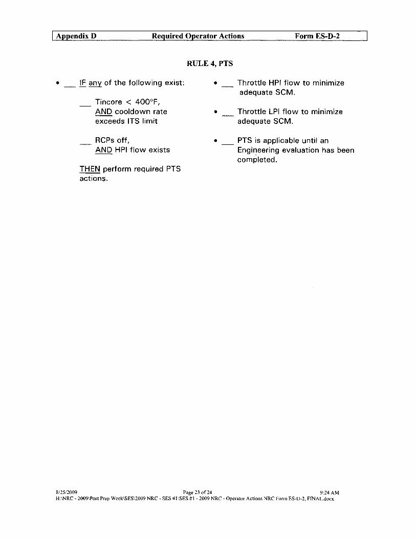
I Appendix D Required Operator Actions Form ES-D-2
• _ IF any of the following exist:
Tincore < 400°F, AND cooldown rate exceeds ITS limit
RCPs off, AND HPI flow exists
THEN perform required PTS actions.
RULE 4, PTS
•
•
Throttle HPI flow to minimize adequate SCM.
Throttle LPI flow to minimize adequate SCM.
• _ PTS is applicable until an Engineering evaluation has been completed.
8/25/2009 Page 23 of24 9:24 AM H:INRC - 2009\Post Prep Week\sES\2009 NRC - SES #1\sES #1 - 2009 NRC - Operator Actions NRC Form ES-D-2, FlNAL.docx

I Appendix D Required Operator Actions Form ES-D-2
RULE 7, PZR LEVEL CONTROL
1 IF PZR level is < PZR level band, THEN restore PZR level.
2 !E. PZR level does NOT recover, THEN establish manual --HPI flow.
3 !E. PZR level recovers, THEN restore normal PZR conditions.
[Rule 2, HPI Control]
PZR Level Band
Rx at power> 20% 200 in to 240 in
Rx at power :S 20% 1 20 in to 200 in
Rx tripped 50 in to 1 20 in
• Cycle appropriate BWST to MUP valve to maintain MUT level 2: 55 in:
1_ MUV-73 1_ MUV-58
• Close MUV-49
1 _ Open MUV-24
2 _ Notify SSO to evaluate Emergency Plan entry.
3 _ !E. PZR level does NOT recover, THEN start second MUP and required cooling pumps.
[Rule 5, Diesel Load Control]
4 _ !E. PZR level does NOT recover, THEN open additional HPI valves.
5 _ !E. PZR level does NOT recover, THEN close MUP to MUT recircs: --
I_ MUV-53 1_ MUV-257!
• _ !E. adequate SCM exists, AND letdown is desired, THEN CONCURRENTLY PERFORM --EOP-14, Enclosure 4, Letdown Recovery (if accessible).
8/25/2009 Page 24 of 24 9:24 AM H:\NRC - 2009\Post Prep WeekISES\2009 NRC - SES #1 ISES #1 - 2009 NRC - Operator Actions NRC Form ES-D-2, FlNAL.docx
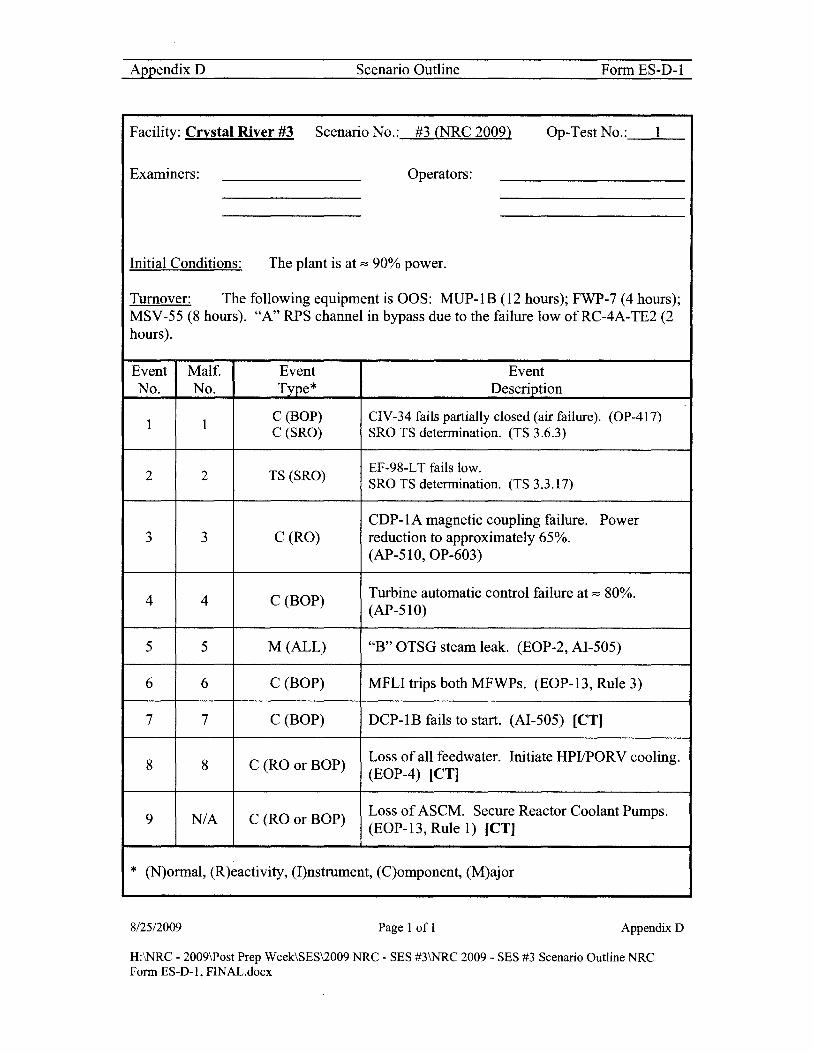
AppendixD Scenario Outline Form ES-D-l
Facility: Crystal River #3 Scenario No.: #3 (NRC 2009) Op-Test No.: 1
Examiners: Operators:
Initial Conditions: The plant is at :=::: 90% power.
Turnover: The following equipment is OOS: MUP-IB (12 hours); FWP-7 (4 hours); MSV-55 (8 hours). "A" RPS channel in bypass due to the failure low of RC-4A-TE2 (2 hours).
Event Malf. Event Event No. No. Type* Description
1 1 C (BOP) CIV-34 fails partially closed (air failure). (OP-417) C (SRO) SRO TS determination. (TS 3.6.3)
2 2 TS (SRO) EF-98-LT fails low. SRO TS detennination. (TS 3.3.17)
CDP-IA magnetic coupling failure. Power 3 3 C(RO) reduction to approximately 65%.
(AP-51O,OP-603)
4 4 C (BOP) Turbine automatic control failure at :=::: 80%. (AP-51O)
5 5 M (ALL) "B" OTSG steam leak. (EOP-2, AI-505)
6 6 C (BOP) MFLI trips both MFWPs. (EOP-13, Rule 3)
7 7 C (BOP) DCP-IB fails to start. (AI-505) [CT]
8 8 C (RO or BOP) Loss of all feedwater. Initiate HPVPORV cooling. (EOP-4) [CT]
9 N/A C (RO or BOP) Loss of ASCM. Secure Reactor Coolant Pumps. (EOP-13, Rule 1) [CT]
* (N)ormal, (R)eactivity, (I)nstrument, (C)omponent, (M)ajor
812512009 Page 1 of 1 Appendix D
H:\NRC - 2009\Post Prep Week\SES\2009 NRC - SES #3\NRC 2009 - SES #3 Scenario Outline NRC Form ES-D-I, FINAL.docx

Narrative Summary NRC 2009 Scenario #3
Plant is initialized at 90% power for turbine valve testing. MUP-lB, FWP-7 and MSV-55 are OOS. RPS Channel "A" is bypassed due to the failure of RC-4A-TE2.
Soon after turnover CIV-34 will fail closed. Actions to secure CIP-3A, starting CIP-3B and swapping Cavity Cooling fans are required. TS 3.6.3, Condition C, should be addressed with actions to isolate the flowpath within 4 hours.
Once TS actions are completed EF-98-LT (EFT level) fails low and TS 3.3.17 is addressed. Condition A should be entered with the action to restore the channel to operable status within 30 days.
Following the failure ofEF":98-LT the magnetic coupling on CDP-IA experiences a control circuit failure. Power must be lowered quickly so that MFW booster pump suction is not lost. AP-510, Rapid Power Reduction, will be entered and power reduced to about 65%. At about 80% power automatic control of the turbine will be lost. The crew must recognize this failure and take manual control of the turbine for the remainder of the down power.
After the plant is stabilized the "B" OTSG develops a steam leak. Plant shutdown is started with the Turbine in manual. SG/Rx Master station may also be taken to manual. After the reactor is tripped the steam leak increases and "B" OTSG is isolated. When "B" MFLI is actuated both the "A" and "B" MFWPs will trip due to a failure of the EFIC FWP trip logic circuitry.
DCP-IB fails to start when HPI is initiated resulting in a loss of cooling to DHP-IB, RWP-3B and MUP-IC. The "B" train DC cooled equipment must be secured and MUP-IC either secured or placed on SW cooling leT].
EFP-2 will stop supplying EFW when the "B" OTSG depressurizes. EFP-3 will trip due to a mechanical failure. EFP-l breaker will not close when demanded. EOP-4, Inadequate Heat Transfer, will be entered based on symptoms of inadequate primary to secondary heat transfer or loss of all main and emergency feedwater. HPIIPORV cooling must be established [eT). An ALERT condition will exist when HPIIPORV cooling is started.
If a loss of ASCM condition exists the RCPs must be secured within 1 minute [eT).
This scenario may be terminated when HPIIPORV cooling is established and incore temperatures are starting to lower.
8/25/2009 Page 10f6 9:25 AM
H:\NRC - 2009\Post Prep Week\SES\2009 NRC - SES #3\SES #3 - 2009 NRC - Summary - Turnover FINAL.docx

Procedures used: (ARs not listed)
OP-417 AP-51O EOP-2 OP-603 EOP-4
AI-505 EOP-13 EOP-14
Target Quantitative Attributes - Scenario 3 - NRC 2009 Actual Attributes
1. Total Malfunctions (5-8) 8
2. Malfunctions after EOP entry (1-2) 2
3. Abnormal Events (2-4) 2
4. Major Transients (1-2) 1
5. EOPs entered requiring substantive actions (1-2) 2
6. EOP contingencies requiring substantive actions (0-2) 0
7. Critical Task (2-3) 3
8/25/2009 Page 2 of6 9:25 AM
H:\NRC - 2009\Post Prep WeekISES\2009 NRC - SES #3ISES #3 - 2009 NRC - Summary - Turnover FINAL.docx

SHIFT TURNOVER
A. Initial Conditions:
1. Time in core life - 300 EFPD 2. Shift: [X] Day [] Night 3. Rx power and power history - 90% for 1 hour. Previously 100% for 40 days. 4. Boron concentration - 976 ppmb 5. Xenon - See Saxon 6. RCS Activity - See Status Board 7. EOOS Condition: Green 8. Protected Train - "A" Train
B. Tech. Spec. Action requirement(s) or other administrative requirement(s) in effect:
• TS 3.7.5, Condition A, MSV-55. Condition entered 8 hours ago. • TS 3.3.1, Condition A, RC-4A -TE2. Condition entered 2 hours ago. • CP-500, FWP-7 • Fire Protection Plan, Table 6.9A, MUP-IB and MSV-55
C. Clearances in effect:
• FWP-7 for bearing replacement. Expected return to service in 24 hours. • MUP-l B for wet alignment. Expected return to service in 4 hours. • MSV-55 for MOV inspection. Expected return to service in 12 hours.
D. Significant problems/abnormalities:
• (Management decision) Startup Transformer is supplying the Unit buses due to the scheduled turbine valve testing.
E. Evolutions/maintenance for the on-coming shift:
• Maintenance to continue work on MUP-IB, MSV-55 and RC-4ATE2 (failed low).
• Plant currently at 90% power for turbine valve testing. Testing is scheduled to start when the oncoming crew returns from the pre-job briefing ..
F. CRS - Instruct the ROs to walk down the main control board.
G. Required Emergency Plan Implementation
8/25/2009
[ ] Full Implementation, including all required notifications. [ ] Initial/upgrade classifications - internal notifications. [X] None
Page 3 of6
H:INRC - 2009\Post Prep WeekISES\2009 NRC - SES #3ISES #3 - 2009 NRC - Summary - Turnover FINALdocx
9:25 AM

8/25/2009
Examination SetuplExecution Scenario 3
INITIAL CONDITIONS
A. "Restore" the simulator to IC# 172 in Exam 4 directory.
B. "Unfreeze" the simulator and ensure the following configuration is setup:
1. MUP-IB in Normal-After-Stop 2. MUP-IA running 3. RPS Channel "A" in manual bypass. 4. MSV -55 selected closed 5. Unit buses on Startup transformer 6. AULD Nozzle and LEFM quality OFF 7. AULD Alerts acknowledged
C. "Freeze" the simulator and enter 'Exam 4' lesson plan directory:
1. "Start" Lesson Plan SES #3 NRC 2009
D. "Unfreeze" the simulator and "Trigger" Setup Step(s) which will:
See Simulator lesson plan
E. Tag out the following equipment:
1. Place CIT on FWP-7 CIS in Normal-After-Stop 2. Place CIT on MUP-IB CIS in Normal-After-Stop I "A" side 3. Place CIT on MUP-lB CIS in Normal-After-Stop I "B" side 4. Place CIT on MSV -55 in close position 5. Place Protected Train sign on the "A" Train
F. Additional Modifications required to the Ie.
I. Ensure SPDS selected to NORMIIMB and history traces cleared and history trace selected. Also ensure "A" and "B" SPDS are properly selected for RCS Loops and Primary instruments selected.
2. Ensure SPDS on CNO/SSO/ST A computers displaying correct data for Ie.
3. Ensure Group 59 indicative of current reactor power.
4. Acknowledge computer and annunciator alarms.
5. Ensure proper PICS groups displayed on overhead screens.
6. Consumable copy ofOP-417. Copy ofPT-325 is NOT required.
7. Copy of OP-204 signed thru Step 4.4.4 with note on Step 4.4.5.
Page 40f6 9:25AM
H:\NRC • 2009\Post Prep Week\sES\2009 NRC· SES #3\SES #3 ·2009 NRC· Summary. Turnover FINAL.docx

Booth Operator Actions NRC 2009 Scenario #3
START DATA RECORDER
A. EVENT #1 When directed input the CIV -34 failure. [Trigger Step #1: CIV-34 fail partially closed]
Role Play: If contacted as PPO to check out CIV -34 wait about 2 minutes then report that CIV-34 is about Y:z open.
B. EVENT #2 When directed input the EF-98-LT failure. [Trigger Step #2: EF-98-LT fail low]
C. EVENT #3 When directed input CDP-1A control pot failure. [Trigger Step #3: CDP-1A Output Control Pot Fail Low - Ramped over 3 minutes]
D. EVENT #4 Turbine automatic control circuit failure. [Failure included in setup step. Activated at 80% power.]
E. EVENT #5 When directed input "B" OTSG steam leak. [Trigger Step #4: "B" OTSG Steam Leak - Ramped over 5 minutes]
Role Play: If contacted as SPO to check out the IB fIre alert wait 2 minutes then report steam coming out ofthe scuppers from the lB.
F. EVENTs #6, 7, 8 & 9
8125/2009
Loss of both MFWPs, DCP-lB failure, EFP-1 and EFP-3 failures. [Failures included in setup step]
Role Play: If the crew decides to place MUP-l C on SW then trigger the step and report back in 5 minutes that SW cooling is aligned. Do NOT align cooling until after SCM has been lost. [Trigger Step #5: SWAP MUP-1C TO SW COOLING]
Role Play: If contacted as the SPO to perform EOP-14, Enclosure 1, wait ~23 minutes and report completion. [Open Lesson Plan: Misc\Enc_l.lsn, execute and trigger]
Page 5 of6 9:25 AM
H:INRC - 2009\Post Prep WeekISES\2009 NRC - SES #3ISES #3 - 2009 NRC - Summary - Turnover FINAL.docx

8/25/2009
Role Play: If contacted as the PPO to perform EOP-14, Enclosure 2, wait ~ 15 minutes and report completion. [Open Lesson Plan: Misc\Enc_2.lsn, execute and trigger]
Page 6 of6 9:25 AM
H:\NRC - 2009\Post Prep Week\sES\2009 NRC - SES #3\SES #3 - 2009 NRC - Summary - Turnover FINAL.docx
8/25/2009
Role Play: If contacted as the PPO to perform EOP-14, Enclosure 2, wait ~ 15 minutes and report completion. [Open Lesson Plan: Misc\Enc_2.lsn, execute and trigger]
Page 6 of6 9:25 AM
H:\NRC - 2009\Post Prep Week\sES\2009 NRC - SES #3\SES #3 - 2009 NRC - Summary - Turnover FINAL.docx

I Appendix D Required Operator Actions Form ES-D-2
Op-Test No.: 1 Scenario No.: 3 Event No.: 1 Rev.: 1
Event Description: (Examiner Cue) Soon after turnover CIV-34 will fail partially closed [MALF]. Actions to secure CIP-3A, starting CIP-3B and swapping Cavity Cooling fans are required. TS 3.6:3, Condition C should be addressed with actions to isolate the flowpath within 4 hours.
Time
8/25/2009
Position
BOP
Applicant's Actions or Behavior
• Announce/acknowledge alarm: o (C-2-14) "SW ISO Valve Air Failure"
• Reviews AR-303 • Diagnoses failure
o CIV-34 green light ON (AHHE-14A in) • Informs SRO of air failure to CIV-34 • Recommends swapping Cavity Cooling fans and pumps
• Assists BOP in diagnosing CIV-34 failure • Directs the BOP to swap Cavity Cooling fans and pumps IA W
OP-417 SRO • Enters TS 3.6.3, Condition C (4 hours to isolate flowpatb)
• Contacts Work Control to initiate repair efforts • May review the SRO checklist for unplanned equipment status
changes
• Swaps Cavity Cooling fans and pumps IA W OP-417, Section 4.9.2 o Stops AHF-2A (Cavity Cooling fan) o Stops CIP-3A (Cavity Cooling pump)
BOP 0 Closes CIV-35(AHHE-14A out) o Opens CIV-40 (AHHE-14B out) o Opens CIV-41 (AHHE-14B in) o Starts CIP-3B (Cavity Cooling pump) o Starts AHF-2B (Cavity Cooling fan)
Page 1 of25 2:34PM
H:INRC - 2009\Post Prep Week1SES\2009 NRC - SES #3ISES #3 - 2009 NRC - Operator Actions NRC Form ES-D-2, FINAL.docx

I Appendix D Required Operator Actions Form ES-D-2
Op-TestNo.:l Scenario No.: 3 Event No.: 2 Rev.: 1
Event Description: (Examiner Cue) EF-98-LT (EF tank level) fails low. (MALF) TS 3.3.17 entry required.
Time
8/25/2009
Position Applicant's Actions or Behavior
• Announce/acknowledge alarm o (H-7-1) "EFTankLeveILow-Low" o Reviews AR-403
ROIBOP 0 Notes that EF-98-LIl is failed low while EF-99-LII still indicates proper EFT level
o Informs SRO of instrument failure o May dispatch SPO to ensure no leak at EFT-2
• Evaluates TS 3.3.17 for applicability. Enters Condition A, restore in 30 days. (has to use Basis to determine)
• May evaluate TS 3.3.18 for applicability. No entry required. SRO (has to use Basis to determine.)
• Contacts Work Control to initiate repair efforts • May review SRO checklist for unplanned equipment status
change
Page 2 of25 2:34 PM
H:\NRC - 2009\Post Prep Week\sES\2009 NRC - SES #3\SES #3 - 2009 NRC - Operator Actions NRC Fonn ES-D-2, FINAL.docx

I Appendix D Required Operator Actions Form ES-D-2
Op-Test No.: 1 Scenario No.: 3 Event No.: 3/4 Rev.: 1
Event Description: (Examiner Cue) After TS determination the magnetic coupling on CDP-IA experiences a control circuit failure. [MALF). Power must be decreased quickly so that MFW booster pump suction is not lost. AP-510, Rapid Power Reduction, will be entered and power reduced to about 65%. At about 80% power automatic control of the turbine will be lost. [MALF). The crew must recognize this failure and take manual control of the turbine for the remainder of the power decrease.
Time Position Applicant's Actions or Behavior
• Announce/acknowledge alarms o (N-2-2) "Cond Pump A Uncoupled" o (N-1-5) "Hotwell Level High/Low"
• Diagnoses failure
ROIBOP o Large decrease in condensate flow o DFT level lowering o Low motor current on CDP-IA
• May attempt to increase demand on CDP-IA • Reviews AR -602 • Notifies SRO of malfunction • Recommends reducing power
• Acknowledges receipt of alarms • Assists ROIBOP in diagnosing CDP failure • Enters AP-510, Rapid Power Reduction • Directs ROIBOP actions per AP-51 0
o Adjust Load Rate to desired setpoint o Set Unit Load Demand to "10" o Notify personnel of entry into AP-51 0
SRO 0 Maintain PZR level (Rule 7, attached) o Notify Chemistry of power change o Verify Imbalance within limits o When power is < 80% notify SPO to ensure MS is supplying
AS o Maintain DFT level between 8 and 11 feet o If MBV s close, then ensure MBV s remain closed o Verify Aux Transformer is not supplying any bus
8125/2009 Page 3 of25 2:34 PM
H:\NRC - 2009\Post Prep Week\SES\2009 NRC - SES #3\sES #3 - 2009 NRC - Operator Actions NRC Form ES-D-2, FINAL.docx

I Appendix D Required Operator Actions Form ES-D-2
Op-Test No.: 1 Scenario No.: 3 Event No.: 3/4 Rev.: 1
Event Description: (Examiner Cue) After TS determination the magnetic coupling on CDP-IA experiences a control circuit failure. [MALF]. Power must be decreased quickly so that MFW booster pump suction is not lost. AP-510, Rapid Power Reduction, will be entered and power reduced to about 65%. At about 80% power automatic control of the turbine will be lost. [MALF]. The crew must recognize this failure and take manual control of the turbine for the remainder of the power decrease.
Time Position
RO
BOP
SRO
8/25/2009
AQQlicant's Actions or Behavior
• Perform actions as directed by the SRO per AP-51 0 o Adjust Load Rate to desired setpoint o Set Unit Load Demand to "10" o Verify Imbalance within limits o Maintain DFT level between 8 and 11 feet o If MBV s close, then ensure MBV s remain closed
• Perform actions as directed by the SRO per AP-510 o Notify personnel of entry into AP-51O o Maintain PZR level (Rule 7, attached) o Notify Chemistry of power change o When power is < 80% notify SPO to ensure MS is supplying
AS o Maintain DFT level between 8 and 11 feet o Verify Aux Transformer is not supplying any bus
• Assists ROIBOP in diagnosing turbine failure • Directs BOP to take manual control of the turbine and maintain
header pressure as power lowers • Directs the RO to continue the down power (may use SG/RX
Master and Turbine or just Turbine) • Directs ROIBOP to stabilize plant parameters at approximately
65% • Contacts Work Control to initiate repair efforts • May review SRO checklist for unplanned equipment status
change
Page 4 of25 2:34 PM
H:INRC - 2009\Post Prep Week\sES\2009 NRC - SES #3\SES #3 - 2009 NRC - Operator Actions NRC Fonn ES-D-2. FINAL.docx
I Appendix D Required Operator Actions Form ES-D-2
Op-Test No.: 1 Scenario No.: 3 Event No.: 3/4 Rev.: 1
Event Description: (Examiner Cue) After TS determination the magnetic coupling on CDP-IA experiences a control circuit failure. [MALF]. Power must be decreased quickly so that MFW booster pump suction is not lost. AP-510, Rapid Power Reduction, will be entered and power reduced to about 65%. At about 80% power automatic control of the turbine will be lost. [MALF]. The crew must recognize this failure and take manual control of the turbine for the remainder of the power decrease.
Time Position
RO
BOP
SRO
8/25/2009
Applicant's Actions or Behavior
• Perform actions as directed by the SRO per AP-51 0 o Adjust Load Rate to desired setpoint o Set Unit Load Demand to "10" o Verify Imbalance within limits o Maintain DFT level between 8 and 11 feet o If MBV s close, then ensure MBV s remain closed
• Perform actions as directed by the SRO per AP-510 o Notify personnel of entry into AP-51O o Maintain PZR level (Rule 7, attached) o Notify Chemistry of power change o When power is < 80% notify SPO to ensure MS is supplying
AS o Maintain DFT level between 8 and 11 feet o Verify Aux Transformer is not supplying any bus
• Assists ROIBOP in diagnosing turbine failure • Directs BOP to take manual control of the turbine and maintain
header pressure as power lowers • Directs the RO to continue the down power (may use SG/RX
Master and Turbine or just Turbine) • Directs ROIBOP to stabilize plant parameters at approximately
65% • Contacts Work Control to initiate repair efforts • May review SRO checklist for unplanned equipment status
change
Page 4 of25 2:34 PM
H:INRC - 2009\Post Prep Week\sES\2009 NRC - SES #3\SES #3 - 2009 NRC - Operator Actions NRC Fonn ES-D-2. FINAL.docx

I Appendix D Required Operator Actions Form ES-D-2
Op-Test No.: I Scenario No.: 3 Event No.: 3/4 Rev.: I
Event Description: (Examiner Cue) After TS determination the magnetic coupling on CDP-IA experiences a control circuit failure. [MALF]. Power must be decreased quickly so that MFW booster pump suction is not lost. AP-510, Rapid Power Reduction, will be entered and power reduced to about 65%. At about 80% power automatic control of the turbine will be lost. [MALF]. The crew must recognize this failure and take manual control of the turbine for the remainder of the power decrease.
Time Position
BOP
RO
8/25/2009
Applicant's Actions or Behavior
• Recognizes turbine failure to lower demand • Announce/acknowledge alarms
o (0-3-4) "Turb Throttle Press RighILow" (possible) o (N-6-4) "Turb ERC on Manual" o (K-6-2) "Unit Master In Track"
• Manually reduces turbine to maintain header pressure (may use OPER Man or OPER Auto)
• Continues manual control until power reduction is completed (approximately 65%)
• Stabilizes plant parameters
• Recognizes turbine failure to lower demand • May take manual control of the SGIRX Master station • Continues power reduction with the Turbine and/or SGIRX
Master station(s) in Manual • Stops power decrease at 60% to 70% power • Monitors DFT level • Stabilizes plant parameters
Page 5 of25 2:34PM
H:\NRC - 2009\Post Prep WeekISES\2009 NRC - SES #3\sES #3 - 2009 NRC - Operator Actions NRC Form ES-D-2, FINAL.docx

I AppendixD Required Operator Actions Form ES-D-2
Op-Test No.: 1 Scenario No.: 3 Event No.: 5/6 Rev.: 1
Event Description: (Examiner Cue) After the plant is stabilized the "B" OTSG develops a steam leak [MTJ. Plant shutdown is started with the Turbine and/or SGIRx Master stations in manual. After the reactor is tripped the steam leak rises and the "B" OTSG is isolated. When MFLI is actuated both the "A" and "B" MFWPs will trip due to a failure ofthe EFIC FWP trip logic circuitry [MALFJ.
Time Position Applicant's Actions or Behavior
CREW • Recognize indications of a steam leak in the IB
• Announce/acknowledge alarms o (F-3-2) Aux Bldg Fire Alert
BOP • Reviews AR -401 • Notifies SRO of failure • Directs SPO to investigate
• Assists the ROIBOP in diagnosing the failure • May re-enter AP-51 0, Rapid Power Reduction • May direct ROIBOP actions per AP-51O
o Adjust Load Rate to desired setpoint o Set Unit Load Demand to "10" (should N/A)
• Should direct RO to use SGIRx master station and BOP SRO to use the turbine or BOP to use the turbine only
o Notify personnel of entry into AP-51 0 o Maintain PZR level (Rule 7, attached) o Notify Chemistry of power change o Maintain Imbalance within limits o When power is < 80% ensure MS is supplying AS (N/A)
• Maintain DFT level between 8 and 11 feet
• Assist in diagnosing alarms RO • Starts plant shutdown
• Perform additional actions as directed by the SRO
BOP • Maintains header pressure with Turbine in Manual • Perform additional actions as directed by the SRO
8/25/2009 Page 6 of25 2:34PM
H:\NRC - 2009\Post Prep Week\sES\2009 NRC - SES #3\sES #3 - 2009 NRC - Operator Actions NRC Fonn ES-O-2, FINAL.docx

I Appendix D Required Operator Actions Form ES-D-2
Op-Test No.: 1 Scenario No.: 3 Event No.: 5/6 Rev.: 1
Event Description: (Examiner Cue) After the plant is stabilized the "B" OTSG develops a steam leak [MT]. Plant shutdown is started with the Turbine and/or SGIRx Master stations in manual. After the reactor is tripped the steam leak rises and the "B" OTSG is isolated. When MFLI is actuated both the "A" and "B" MFWPs will trip due to a failure of the EFIC FWP trip logic circuitry [MALF].
Time
8/25/2009
Position Applicant's Actions or Behavior
• Trips the reactor when directed • Perform first pass ofEOP-2 Immediate Actions from memory
o Depress the Rx trip pushbutton o Verify CRD groups 1 through 7 are fully inserted
RO 0 Verify NIs indicate Rx is shutdown o Depress Main Turbine trip pushbutton o Verify TV sand GV s are closed
• Perform second pass ofEOP-2 Immediate Actions with SRO direction
• Direct RO actions per EOP-2 o Depress the Rx trip pushbutton o Verify CRD groups 1 through 7 are fully inserted
SRO 0 Verify NIs indicate Rx is shutdown o Depress Main Turbine trip pushbutton o Verify TV sand GV s are closed
• Directs BOP to determine failed OTSG and isolate
• Depresses Global Silence pushbutton • Isolates the "B" OTSG (STM Gen B MFLI and MSLI isolation
BOP pushbuttons) • Recognizes that both MFWPs tripped when MFLI was actuated • Notifies SRO ofloss of both MFWPs
Page 70f25 2:34 PM
H:\NRC· 2009\Post Prep Week\sES\2009 NRC - SES #3\sES #3 - 2009 NRC - Operator Actions NRC Form ES-D-2. FINAL.docx
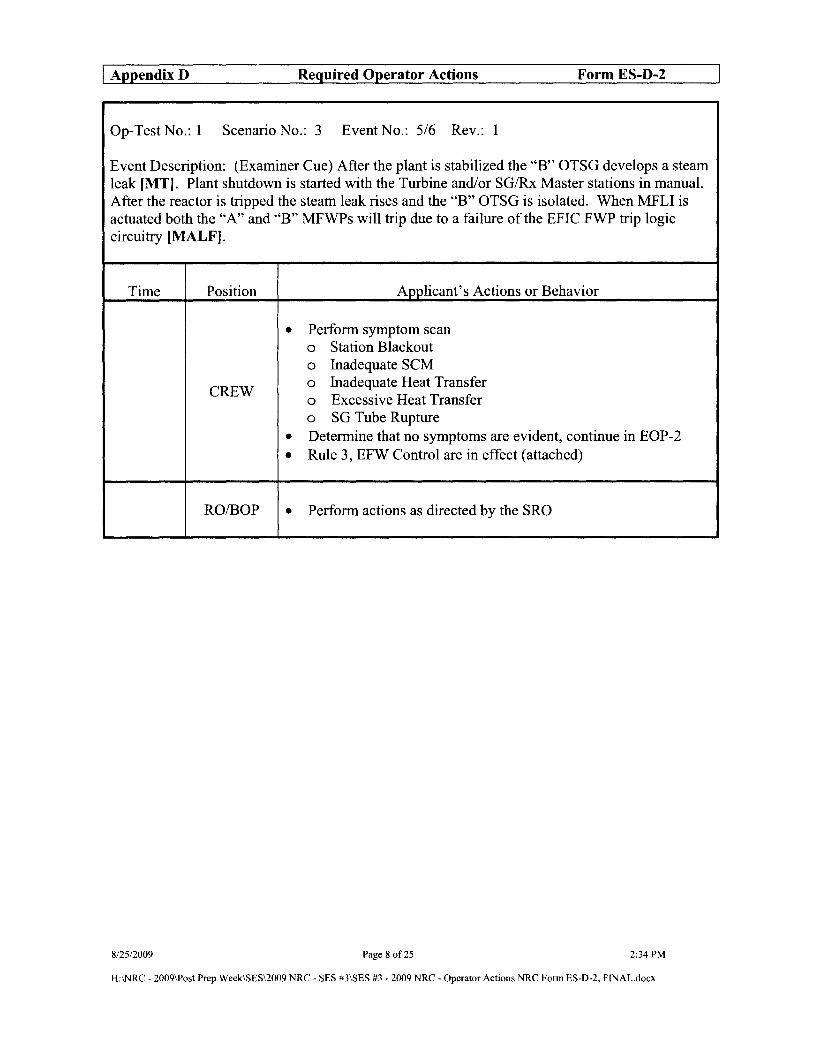
I AppendixD Required Operator Actions Form ES-D-2
Op-Test No.: 1 Scenario No.: 3 Event No.: 5/6 Rev.: 1
Event Description: (Examiner Cue) After the plant is stabilized the "B" OTSG develops a steam leak [MT). Plant shutdown is started with the Turbine and/or SGIRx Master stations in manual. After the reactor is tripped the steam leak rises and the "B" OTSG is isolated. When MFLI is actuated both the "A" and "B" MFWPs will trip due to a failure of the EFIC FWP trip logic circuitry [MALF).
Time Position Applicant's Actions or Behavior
• Perform symptom scan o Station Blackout o Inadequate SCM
CREW o Inadequate Heat Transfer o Excessive Heat Transfer o SG Tube Rupture
• Determine that no symptoms are evident, continue in EOP-2 • Rule 3, EFW Control are in effect (attached)
ROIBOP • Perform actions as directed by the SRO
8/25/2009 Page 8 of25 2:34 PM
H:INRC - 2009\Post Prep Week\sES\2oo9 NRC - SES #3\SES #3 - 2009 NRC - Operator Actions NRC Form ES-D-2, FINAL.docx

I Appendix D Required Operator Actions Form ES-D-2
Op-Test No.: I Scenario No.: 3 Event No.: 7 Rev.: I
Event Description: (Automatic Parameter Cue) DCP-IB fails to start [MALF] when HPJg is initiated resulting in a loss of cooling to DHP-IB, RWP-3B. MUP-IC must be secured or placed on SW cooling [CT]. DHP-IB and RWP-3B may also be secured.
Time Position Applicant's Actions or Behavior
• Perform Rule 2, HPJ Control (attached) o Bypass or Reset ES actuation o Open MUP recirc valves prior to throttling < 200 gpm/pump
• Determine that DCP-IB failed to start o (D-5-6) "BSIDH Pump B DC Flow Low"
BOP 0 Amber light remains on for DCP-IB on "B" ES Status Panel • Attempt to start DCP-IB • Notify SRO of failure
o Secures MUP-lC OR places on SW cooling leT] o Secures RWP-3B and DHP-IB
• May note time when RCPs must be secured
• Directs BOP to: o Attempt start ofDCP-IB
SRO 0 Secure DC cooled equipment o Shutdown MUP-IC or place on SW o Stop RCPs within 30 minutes due to loss of CBO flow
8/25/2009 Page 9 of25 2:34 PM
H:INRC - 2009\Post Prep Week\sES\2009 NRC - SES #3\SES #3 - 2009 NRC - Operator Actions NRC Form ES-D-2, FINAL.docx

I Appendix D Required Operator Actions Form ES-D-2
Op-Test No.: I Scenario No.: 3 Event No.: 8/9 Rev.: I
Event Description: (Automatic Parameter Cue) EFP-2 will stop supplying EFW when the "B" OTSG depressurizes. EFP-3 will trip due to a mechanical failure [MALF]. EFP-l breaker will not close when demanded. EOP-4, Inadequate Heat Transfer, will be entered based on symptoms of inadequate primary to secondary heat transfer or loss of all main and emergency feedwater. HPIIPORV cooling must be established [CT]. An ALERT should be declared when HPIIPORV cooling is started. Once adequate SCM is lost RCPs must be secured within 1 minute [CT].
Time Position Applicant's Actions or Behavior
• Perform Rule 3, EFW Control (attached) • Recognize EFP-2 flow decrease (isolation of"B" OTSG) • Recognize loss ofEFP-3
ROIBOP o (H-8-3) "EFP 3 Start Failure" o NoEFW flow o Green light on control handle
• Notifies SRO of malfunction
8125/2009 Page 10 of25 2:34 PM
H:INRC - 2009\Post Prep Week\sES\2009 NRC - SES #3\sES #3 - 2009 NRC - Operator Actions NRC Form ES-D-2, FINAL.docx

I AppendixD Required Operator Actions Form ES-D-2
Op-Test No.: 1 Scenario No.: 3 Event No.: 8/9 Rev.: 1
Event Description: (Automatic Parameter Cue) EFP-2 will stop supplying EFW when the "B" OTSG depressurizes. EFP-3 will trip due to a mechanical failure [MALF]. EFP-I breaker will not close when demanded. EOP-4, Inadequate Heat Transfer, will be entered based on symptoms of inadequate primary to secondary heat transfer or loss of all main and emergency feedwater. HPIIPORV cooling must be established [CT]. An ALERT should be declared when HPVPORV cooling is started. Once adequate SCM is lost RCPs must be secured within 1 minute [CT].
Time Position Applicant's Actions or Behavior • Enters EOP-4 and directs ROIBOP actions
o Notify personnel o Verify EFW or AFW pumps running
• Directs closure of EFIC and AFW control valves • Directs RO or BOP to concurrently perform EOP-14,
Enclosure 7 o Notify PPO to perform EOP-14, Enclosure 2 o Adjust MVV-31 setpoint to 100 inches (use Rule 7) o Record initial Tincore temp o Minimize RCS pressure rise
• PZR spray, PZR heaters, HPI flow o Reduce running RCPs to 1 per loop o Waits at step 3.13 until any of the following occur:
• RCS pressure approaches NDT limit • PORV automatically opens • RCS pressure is ::: 2400 psig
o Determines HPIIPORV cooling is required SRO o Actuates HPI
• If MUP-l C cooling water has not been swapped to SW then MUP-IC must be secured
o Ensure proper HPI alignment o Ensure HPI recirc valves to sump closed o Establish HPI PORV cooling
• Ensure RCV-ll is open and open PORV o Select all PZR heaters to OFF o Reduces RCPs to only 1 running o Ensure PZR spray valve in AUTO
• Should recognize entry into an Alert condition. • Directs RCP shutdown based on either of the following: [CT]
o Within 1 minute of Loss of ASCM o If incore temp rises::: 50° F above initial value in EOP-4
• Goes to EOP-8B, HPI Cooldown
8/25/2009 Page 11 of25 2:34PM
H:\NRC - 2009\Post Prep Week\sES\2009 NRC - SES #3\sES #3 - 2009 NRC - Operator Actions NRC Fonn ES-D-2, FINAL.docx

I AppendixD Required Operator Actions Form ES-D-2
Op-Test No.: 1 Scenario No.: 3 Event No.: 8/9 Rev.: 1
Event Description: (Automatic Parameter Cue) EFP-2 will stop supplying EFW when the "B" OTSG depressurizes. EFP-3 will trip due to a mechanical failure [MALF]. EFP-I breaker will not close when demanded. EOP-4, Inadequate Heat Transfer, will be entered based on symptoms of inadequate primary to secondary heat transfer or loss of all main and emergency feedwater. HPIIPORV cooling must be established leT]. An ALERT should be declared when HPIIPORV cooling is started. Once adequate SCM is lost RCPs must be secured within 1 minute leT].
Time Position
ROIBOP
8/25/2009
Applicant's Actions or Behavior • Performs actions directed by the SRO
o Notify personnel o Verify EFW or AFW pumps running
• Closes EFIC and AFW control valves • Concurrently performs EOP-14, Enclosure 7
o Notify PPO to perform EOP-14, Enclosure 2 o Adjust MUV-31 setpoint to 100 inches o Record initial Tincore temp o Minimize RCS pressure rise
• PZR spray, PZR heaters, HPI flow o Reduce running RCPs to 1 per loop o Waits at step 3.13 until any of the following occur:
• RCS pressure approaches NDT limit • PORV automatically opens • RCS pressure is :::: 2400 psig
o Concurs that HPIIPORV cooling is required o Actuates HPI
• IfMUP-IC cooling water has not been swapped to SW then MUP-IC must be secured
o Ensures at least 1 train ofHPI is properly aligned o Ensures HPI recirc valves to sump closed o When at least 1 train of HPI flow is established opens
PORV leT] o Selects all PZR heaters to OFF o Reduces RCPs to one o Ensures PZR spray valve in AUTO
• Performs Rep shutdown based on either of the following: leT] o Within I minute of Loss of ASCM o If incore temp rises:::: 500 F above initial value in EOP-4
Page 12 of25 2:34PM
H:INRC - 2009\Post Prep Week\sES\2009 NRC - SES #3\sES #3 - 2009 NRC - Operator Actions NRC Form ES-D-2, FINAL.docx

I Appendix D Required Operator Actions Form ES-D-2
Op-Test No.: 1 Scenario No.: 3 Event No.: 8/9 Rev.: 1
Event Description: (Automatic Parameter Cue) EFP-2 will stop supplying EFW when the "B" OTSG depressurizes. EFP-3 will trip due to a mechanical failure [MALF]. EFP-I breaker will not close when demanded. EOP-4, Inadequate Heat Transfer, will be entered based on symptoms of inadequate primary to secondary heat transfer or loss of all main and emergency feedwater. HPIIPORV cooling must be established [CT]. An ALERT should be declared when HPIIPORV cooling is started. Once adequate SCM is lost RCPs must be secured within 1 minute [CT].
Time Position Applicant's Actions or Behavior
• Performs EOP-14, Enclosure 7 o Verifies EFP-3 is not running and goes to Step 7.6 o Verifies EFP-2 is not running and goes to Step 7.8
ROIBOP o Verifies EDG A is not supplying A ES bus o Verifies EFP-I is available o Ensures EFP -I is running
• Notifies SRO ofEFP-1 failure to start per Enclosure 7
Scenario may be terminated when HPlIPORV cooling is established and incore temperatures are lowering.
8/25/2009 Page 13 of25 2:34 PM
H:INRC - 2009\Post Prep Week\sES\2009 NRC - SES #3\sES #3 - 2009 NRC - Operator Actions NRC Form ES-O-2, FINAL.docx

I Appendix D Required Operator Actions Form ES-D-2
RULE 1, LOSS OF SCM
• _ !.E < 1 min has elapsed since losing adequate SCM, THEN immediately stop all RCPs.
• _ !.E RCPs were NOT stopped within 1 min,
•
THEN ensure all operating RCPs remain running until ~ of the following exist:
SCM is restored
_ LPI flow > 1400 gpm in each injection line.
Manually actuate ES.
• _ Depress "ISCM" push buttons for EFIC channels A and B.
• Ensure Tincore is selected on SPDS.
8/25/2009 Page 14 of25
• _ Progress toward a maximum plant cooldown to achieve CFT and LPI flow as soon as possible.
• Depress "HPI MAN ACT" push buttons on Trains A and B.
• Depress "RB ISO MAN ACTUATION" push buttons on Trains A and B.
• _ !.E LPI has NOT actuated, AND RCS PRESS $; 300 psig, THEN depress "LPI MAN ACT" push buttons on Trains A and B.
2:34 PM
H:\NRC - 2009\Post Prep WeekISES\2009 NRC - SES #3ISES #3 - 2009 NRC - Operator Actions NRC Form ES-D-2, FINAL.docx
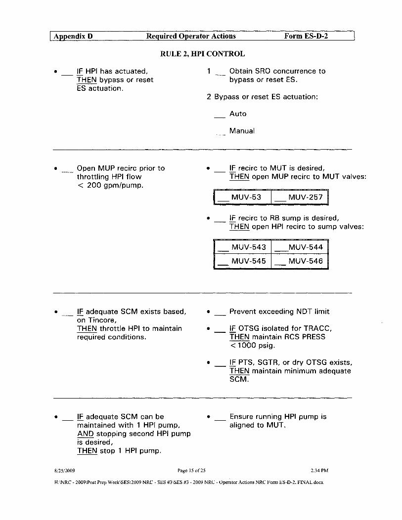
I Appendix D Required Operator Actions Form ES-D-2
RULE 2, HPI CONTROL
• _ !E HPI has actuated, THEN bypass or reset ES actuation.
• Open MUP recirc prior to throttling HPI flow < 200 gpm/pump.
• _ !E adequate SCM exists based, on Tincore, THEN throttle HPI to maintain required conditions.
• _ !E adequate SCM can be maintained with 1 HPI pump, AND stopping second HPI pump is desired, THEN stop 1 HPI pump.
8/2512009 Page 15 of25
1 Obtain SRO concurrence to bypass or reset ES.
2 Bypass or reset ES actuation:
Auto
Manual
• _ !E recirc to MUT is desired, THEN open MUP recirc to MUT valves:
1_ MUV-53 1_ MUV-257 ~
• _ IF recirc to RB sump is desired, THEN open HPI recirc to sump valves:
MUV-543 MUV-544 - --MUV-545 MUV-546 - -
• _ Prevent exceeding NDT limit
• _ IF OTSG isolated for TRACC, THEN maintain RCS PRESS --< 1000 psig.
• _ !E PTS, SGTR, or dry OTSG exists, THEN maintain minimum adequate SCM.
• _ Ensure running HPI pump is aligned to MUT.
2:34 PM
H:INRC - 2009\Post Prep Week\sES\2009 NRC - SES #3\sES #3 - 2009 NRC - Operator Actions NRC Form ES-D-2. FINAL.docx

I Appendix D Required Operator Actions Form ES-D-2
RULE 3, EFW/AFW CONTROL
• Ensure available OTSGs are at or trending toward required level.
• IF manual control of EFW flow is desired, THEN establish manual EFIC control.
• _ !E adequate SCM does NOT exist, AND level in available OTSGs is NOT at or trending toward "ISCM" level, THEN establish manual required flow.
"LLL" > 20in
"NAT CIRC" > 70%
"ISCM" > 90%
1 _ Obtain SRO concurrence to place EFIC in manual.
2 _ Control EFW to maintain required EFW flow and OTSG level.
3 _ IF EFW flow is NOT controlled, THEN depress EFIC channels
EFW
AFW
A and B "MANUAL PERMISSIVE" push buttons and close affected EFW block valve.
2 OTSGs > 280 gpm in 1 line to each OTSG
10TSG > 470 gpm in 1 line to 1 OTSG
20TSGs > 250 gpm to < 300 gpm/OTSG
10TSG > 450 gpm to < 600 gpm
• _ IF adequate SCM exists, THEN throttle flow to prevent OTSG PRESS from lowering > 100 psig below desired PRESS.
• Do not allow OTSG level to lower.
8/25/2009 Page 16 of25 2:34 PM
H:\NRC - 2009\Post Prep WeekISES\2009 NRC - SES #3\sES #3 - 2009 NRC - Operator Actions NRC Form ES-D-2, FINAL.docx

I Appendix D Required Operator Actions Form ES-D-2
• _ !E ~ of the following exist:
Tincore < 400°F, AND cooldown rate exceeds ITS limit
RCPs off, AND HPI flow exists
THEN perform required PTS actions.
RULE 4, PTS
•
•
Throttle HPI flow to minimize adequate SCM.
Throttle LPI flow to minimize adequate SCM.
• _ PTS is applicable until an Engineering evaluation has been completed.
8/25/2009 Page 17 of25 2:34 PM
H:\NRC - 2009IPost Prep WeekISES\2009 NRC - SES #3ISES #3 - 2009 NRC - Operator Actions NRC Form ES-D-2, FINAL.docx

I AppendixD Required Operator Actions Form ES-D-2
RULE 7, PZR lEVEL CONTROL
1 IF PZR level is < PZR level band, THEN restore PZR level.
2 !E PZR level does NOT recover, THEN establish manual HPI flow.
3 !E PZR level recovers, THEN restore normal PZR --conditions.
[Rule 2, HPI Control]
8/25/2009 Page 18 of25
PZR Level Band
Rx at power> 20% 200 in to 240 in
Rx at power :S 20% 1 20 in to 200 in
Rx tripped 50 in to 1 20 in
• Cycle appropriate BWST to MUP valve to maintain MUT level?: 55 in:
1_ MUV-73 1_ MUV-58
• Close MUV-49
1 _ Open MUV-24
2 _ Notify SSO to evaluate Emergency Plan entry.
3 _ IF PZR level does NOT recover, THEN start second MUP and required cooling pumps.
[Rule 5, Diesel Load Control]
4 _ IF PZR level does NOT recover, THEN open additional HPI valves.
5 _ IF PZR level does NOT recover, THEN close MUP to MUT recircs:
1_ MUV-53 1_ MUV-257I
• _ IF letdown is desired, THEN CONCURRENTLY PERFORM EOP-14, Enclosure 4, Letdown Recovery (if accessible).
2:34PM
H:INRC - 2009\Post Prep WeekISES\2009 NRC - SES #3ISES #3 - 2009 NRC - Operator Actions NRC Folm ES-D-2, FINAL.docx

I Appendix D Required Operator Actions Form ES-D-2
I
ENCLOSURE 7 EFWP MANAGEMENT
ACTIONS
STATUS
EFW required.
7.1 _ Verify EFP-3 is running.
IF EFP-3 is NOT running, THEN GO TO Step 7.6 in this enclosure.
DETAILS
7.2 IF MFW is NOT available, THEN ensure MFW remains isolated.
• Select MBV to "MAN" and select all FW isolation valves to "CLOSE".
FWvalve AOTSG BOTSG
LLBV FWV-3l FWV-32 - -
MBVtoggle "MAN" "MAN" - -
MBV FWV-30 FWV-29 - -
SUBV FWV-36 FWV-33 - -
Cross-tie FWV-28 FWV-28 - -
Suction FWV-14 FWV-15 - -
8/25/2009 Page 19 of25 2:34 PM
H:INRC - 2009\Post Prep Week1SESI2009 NRC - SES #3ISES #3 - 2009 NRC - Operator Actions NRC Form ES-D-2, FINAL.docx
I

I Appendix D Required Operator Actions Form ES-D-2
ENCLOSURE 7 EFWP MANAGEMENT (CONT'D)
ACTIONS
7.3 _ Verify EFP-2 is running.
7.4
IF EFP-2 is NOT running, THEN EXIT this enclosure.
WHEN available OTSGs are at required level, THEN stop EFP-2
7.S WHEN EFP-2 is shutdown, THEN EXIT this enclosure.
8/25/2009 Page 20 of25
DETAILS
1 _ Ensure available OTSGs are at required level.
See Table 1
2 _ Depress "MANUAL PERMISSIVE" or "TEST RESUL TSIRESET" push button on EFIC channel B. (as required)
3 Ensure EFP-2 steam supply valves are closed:
ASV-204
ASV-S
2:34PM
H:\NRC - 2009\Post Prep Week\sES\2009 NRC - SES #3\sES #3 - 2009 NRC - Operator Actions NRC Fonn ES-D-2, FINAL.docx

I AppendixD Required Operator Actions
ENCLOSURE 7 EFWP MANAGEMENT (CONT'D)
ACTIONS
STATUS
EFP-3 not running.
7.6 _ Verify EFP-2 is running.
IF EFP-2 is NOT running, THEN GO TO Step 7.8 in this enclosure.
Form ES-D-2
DETAILS
7.7 IF OTSG PRESS is ~ 200 psig, AND adequate primary to secondary heat transfer exists, THEN stop RCS cooldown.
• Control OTSG PRESS using TBV s and ADVs.
7.8 IF EDG A is supplying power to A ES 4160V Bus, THEN GO TO Step7.15 in this enclosure.
7.9 _ Verify EFP-l is available.
8125/2009
IF EFP-l is NOT available, THEN GO TO Step 7.15 in this enclosure.
Page 21 of25 2:34 PM
H:INRC - 2009\Post Prep WeekISES\2009 NRC - SES #3ISES #3 - 2009 NRC - Operator Actions NRC Fonn ES-D-2, FINAL.docx
I AppendixD Required Operator Actions Form ES-D-2
I
ENCLOSURE 7 EFWP MANAGEMENT (CONT'D)
ACTIONS
STATUS
EFP-3 not running.
7.6 _ Verify EFP-2 is running.
IF EFP-2 is NOT running, THEN GO TO Step 7.8 in this enclosure.
DETAILS
7.7 IF OTSG PRESS is ~ 200 psig, AND adequate primary to secondary heat transfer exists, THEN stop RCS cooldown.
• Control OTSG PRESS using TBV s and ADVs.
7.8 IF EDG A is supplying power to A ES 4160V Bus, THEN GO TO Step7.15 in this enclosure.
7.9 _ Verify EFP-l is available.
8125/2009
IF EFP-l is NOT available, THEN GO TO Step 7.15 in this enclosure.
Page 21 of25 2:34 PM
H:INRC - 2009\Post Prep WeekISES\2009 NRC - SES #3ISES #3 - 2009 NRC - Operator Actions NRC Fonn ES-D-2, FINAL.docx
I

I Appendix D Required Operator Actions Form ES-D-2
ENCLOSURE 7 EFWP MANAGEMENT (CONT'D)
ACTIONS
I 7.10 _ Ensure EFP-l is running.
8/25/2009
DETAILS
STATUS
EFP-l available.
Page 22 of25
1 _ Depress "MANUAL PERMISSIVE" or "TEST RESULTSIRESET" push buttons on EFIC channel A and B. (as required).
2 Ensure EFP-l EFIC control valves to OTSGs are closed:
AOTSG BOTSG
EFV-58 EFV-57 - -
3 Ensure EFP-l EFW block valves to available OTSGs are open:
AOTSG BOTSG
EFV-14 EFV-33 - -
4 Ensure EFP-3 is in "PULL TO LOCK".
5 Start EFP-l
2:34 PM
H:INRC - 2009\Post Prep Week\sES\2oo9 NRC - SES #3\SES #3 - 2009 NRC - Operator Actions NRC Fonn ES-D-2, FINAL.docx
I

I Appendix D Required Operator Actions Form ES-D-2
ENCLOSURE 7 EFWP MANAGEMENT (CONT'D)
7.11
8125/2009
ACTIONS
Establish EFW flow to each available OTSG.
Page 23 of25
DETAILS
• _ IF adequate SCM exists, AND OTSG level is $; 12Y2 in, THEN feed each available dry OTSG with continuous EFW flow to 1 line within the following limits:
Cooldown rate minimized
See Table 2
EFW or AFW Flow Limit
Any RCP running :::;390 gpm
No RCPs running :::;200 gpm
• _ IF adequate SCM exists, AND OTSG level is > 12Y2 in, THEN ensure EFW flow is controlled.
[Rule 3, EFW/AFW Control]
• _ IF adequate SCM does NOT exist, THEN feed available OTSGs at inadequate SCM flow rate.
[Rule 3, EFW/AFW Control]
2:34 PM
H:INRC - 2009\Post Prep Week\sES\2009 NRC - SES #3\sES #3 - 2009 NRC - Operator Actions NRC Fonn ES-D-2, FINAL.docx

I Appendix D Required Operator Actions Form ES-D-2
ENCLOSURE 7 EFWP MANAGEMENT (CONT'D)
7.12
7.13
ACTIONS
IF EFP-2 is running, THEN stop EFP-2
IF MFW is NOT available, THEN ensure MFW remains isolated.
7.14 WHEN OTSG level in available OTSGs is > l2Y:z in, THEN EXIT this enclosure.
8/25/2009 Page 24 of25
1
DETAILS
WHEN available OTSGs are at required level, THEN ensure EFP-2 steam supply valves are closed:
ASV-204
ASV-5
See Table 1
2 _ Depress "EFW INITIATE" push buttons on EFIC channel A.
• Select MBV to "MAN" and select all FW isolation valves to "CLOSE".
FWvalve AOTSG BOTSG
LLBV FWV-31 FWV-32 - -
MBVtoggle "MAN" "MAN" - -
MBV FWV-30 FWV-29 - -
SUBV FWV-36 FWV-33 - -
Cross-tie FWV-28 FWV-28 - -
Suction FWV-14 FWV-15 - -
2:34 PM
H:\NRC - 2009\Post Prep Week\sES\2oo9 NRC - SES #3\sES #3 - 2009 NRC - Operator Actions NRC Form ES-D-2, FINAL.docx

I Appendix D Required Operator Actions Form ES-D-2
ENCLOSURE 7 EFWP MANAGEMENT (CONT'D)
ACTIONS DETAILS
STATUS
Any of the following exist:
• EDG A supplying power to the A ES 4160V Bus.
• EFP-l not available.
7.15 _ Verify AFW is available.
8/25/2009
IF AFW is NOT available, THEN GO TO Step 7.24 in this enclosure.
Page 25 of25
• _ Verify all of the following exist:
Neither ES 4160V Bus aligned to Alternate AC Diesel
FWP-7 available
CDT-l level> 9 ft
2:34 PM
H:INRC • 2009\Post Prep Week\sES\2009 NRC· SES #3\sES #3 • 2009 NRC· Operator Actions NRC Form ES·D·2, FINAL.docx
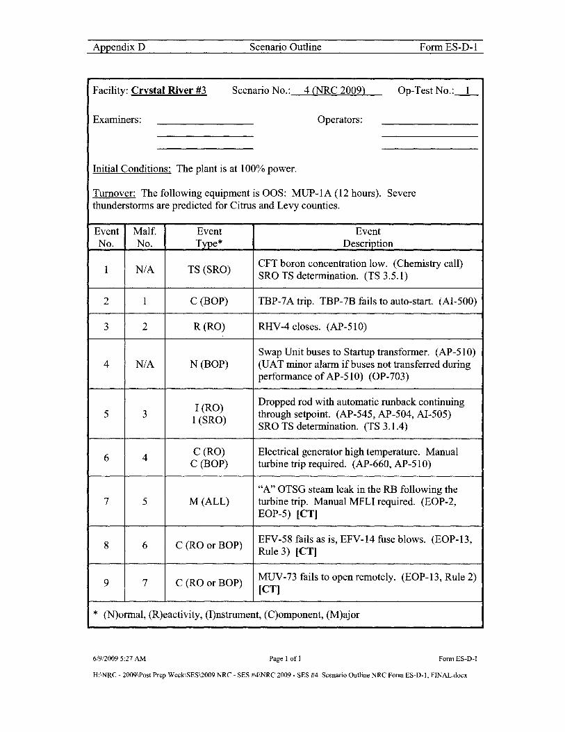
Appendix D Scenario Outline Form ES-D-I
Facility: Crystal River #3 Scenario No.: 4 (NRC 2009) Op-Test No. :_1_
Examiners: Operators:
Initial Conditions: The plant is at 100% power.
Turnover: The following equipment is OOS: MUP-IA (12 hours). Severe thunderstorms are predicted for Citrus and Levy counties.
Event Malf. Event Event No. No. Type * Description
I NIA TS (SRO) CFT boron concentration low. (Chemistry call) SRO TS determination. (TS 3.S.I)
2 I C (BOP) TBP-7 A trip. TBP-7B fails to auto-start. (AI-SOO)
3 2 R(RO) RHV-4 closes. (AP-SIO)
Swap Unit buses to Startup transformer. (AP-SIO) 4 NIA N (BOP) (UAT minor alarm if buses not transferred during
performance of AP-SI 0) (OP-703)
I (RO) Dropped rod with automatic runback continuing
S 3 I (SRO) through setpoint. (AP-S4S, AP-S04, AI-SOS) SRO TS determination. (TS 3.1.4)
6 4 C(RO) Electrical generator high temperature. Manual
C (BOP) turbine trip required. (AP-660, AP-SlO)
"A" OTSG steam leak in the RB following the 7 S M (ALL) turbine trip. Manual MFLI required. (EOP-2,
EOP-S) [CT]
8 6 C (RO or BOP) EFV-S8 fails as is, EFV-14 fuse blows. (EOP-B, Rule 3) [CT]
9 7 C (RO or BOP) MUV-73 fails to open remotely. (EOP-B, Rule 2) [CT]
* (N)ormal, (R)eactivity, (I)nstrument, (C)omponent, (M)ajor
6/9/20095:27 AM Page 1 ofl FonnES-D-1
H:INRC - 2009\Post Prep WeekISES\2009 NRC - SES #4\NRC 2009 - SES #4 Scenario Outline NRC Fonn ES-D-I, FINAL.docx
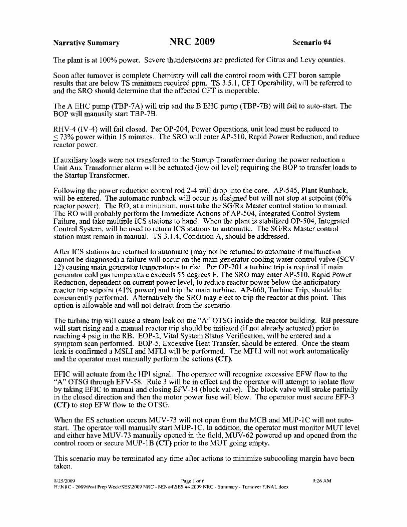
Narrative Summary NRC 2009 Scenario #4
The plant is at 100% power. Severe thunderstonns are predicted for Citrus and Levy counties.
Soon after turnover is complete Chemistry will call the control room with CFT boron sample results that are below TS minimum required ppm. TS 3.5.1, CFT Operability, will be referred to and the SRO should detennine that the affected CFT is inoperable.
The A EHC pump (TBP-7 A) will trip and the B EHC pump (TBP-7B) will fail to auto-start. The BOP will manually start TBP-7B.
RHV-4 (IV -4) will fail closed. Per OP-204, Power Operations, unit load must be reduced to :::: 73% power within 15 minutes. The SRO will enter AP-51O, Rapid Power Reduction, and reduce reactor power.
If auxiliary loads were not transferred to the Startup Transfonner during the power reduction a Unit Aux Transfonner alann will be actuated (low oil level) requiring the BOP to transfer loads to the Startup Transfonner.
Following the power reduction control rod 2-4 will drop into the core. AP-545, Plant Runback, will be entered. The automatic runback will occur as designed but will not stop at setpoint (60% reactor power). The RO, at a minimum, must take the SG/Rx Master control station to manual. The RO will probably perfonn the Immediate Actions of AP-504, Integrated Control System Failure, and take multiple ICS stations to hand. When the plant is stabilized OP-504, Integrated Control System, will be used to return ICS stations to automatic. The SGIRx Master control station must remain in manual. TS 3.1.4, Condition A, should be addressed.
After ICS stations are returned to automatic (may not be returned to automatic if malfunction cannot be diagnosed) a failure will occur on the main generator cooling water control valve (SCV-12) causing main generator temperatures to rise. Per OP-701 a turbine trip is required if main generator cold gas temperature exceeds 55 degrees F. The SRO may enter AP-510, Rapid Power Reduction, dependent on current power level, to reduce reactor power below the anticipatory reactor trip setpoint (41 % power) and trip the main turbine. AP-660, Turbine Trip, should be concurrently perfonned. Alternatively the SRO may elect to trip the reactor at this point. This option is allowable and will not detract from the scenario.
The turbine trip will cause a steam leak on the "A" OTSG inside the reactor building. RB pressure will start rising and a manual reactor trip should be initiated (if not already actuated) prior to reaching 4 psig in the RB. EOP-2, Vital System Status Verification, will be entered and a symptom scan perfonned. EOP-5, Excessive Heat Transfer, should be entered. Once the steam leak is confinned a MSLI and MFLI will be perfonned. The MFLI will not work automatically and the operator must manually perfonn the actions (CT).
EFIC will actuate from the HPI signal. The operator will recognize excessive EFW flow to the "A" OTSG through EFV -58. Rule 3 will be in effect and the operator will attempt to isolate flow by taking EFIC to manual and closing EFV-14 (block valve). The block valve will stroke partially in the closed direction and then the motor power fuse will blow. The operator must secure EFP-3 (CT) to stop EFW flow to the OTSG.
When the ES actuation occurs MUV -73 will not open from the MCB and MUP-l C will not autostart. The operator will manually start MUP-l C. In addition, the operator must monitor MUT level and either have MUV -73 manually opened in the field, MUV -62 powered up and opened from the control room or secure MUP-IB (CT) prior to the MUT going empty.
This scenario may be tenninated any time after actions to minimize subcooling margin have been taken.
8/2512009 Page I of 6 9:26AM H:INRC - 2009\Post Prep Week\SES\2009 NRC - SES #4\SES #4 2009 NRC - Summary - Turnover FINAL.docx

Procedures used: (ARs not listed)
OP-204 AP-SlO EOP-2 OP-402 AP-S4S EOP-S OP-S04 AP-660 EOP-13
AP-S04 EOP-14
Target Quantitative Attributes - Scenario 4 - NRC 2009 Actual Attributes
1. Total Malfunctions (S-8) 7
2. Malfunctions after EOP entry 0-21 2
3. Abnormal Events (2-4) 3
4. Major Transients (1-2) I
S. EOPs entered requiring substantive actions (1-2) 2
6. EOP contingencies requiring substantive actions (0-2) 1
7. Critical Task (2-3) 3
8/25/2009 Page 2 of 6 9:26 AM H:\NRC - 2009\Post Prep Week\SESI2OO9 NRC - SES #4\SES #4 2009 NRC - Summary - Turnover FINAL.docx
Procedures used: CARs not listed)
OP-204 AP-SlO EOP-2 OP-402 AP-S4S EOP-S OP-S04 AP-660 EOP-13
AP-S04 EOP-14
Target Quantitative Attributes - Scenario 4 - NRC 2009 Actual Attributes
1. Total Malfunctions (S-8) 7
2. Malfunctions after EOP entry (1-2) 2
3. Abnormal Events (2-4) 3
4. Maior Transients (1-2) I
S. EOPs entered requiring substantive actions JI-2) 2
6. EOP contingencies requiring substantive actions (0-2} 1
7. Critical Task (2-3) 3
8/25/2009 Page 2 of 6 9:26 AM H:\NRC - 2009\Post Prep Week\SESI2OO9 NRC - SES #4\SES #4 2009 NRC - Summary - Turnover FINAL.docx
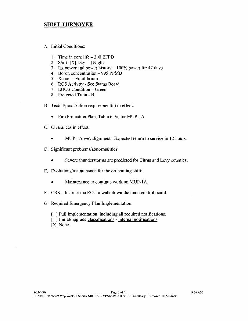
SHIFT TURNOVER
A. Initial Conditions:
1. Time in core life - 300 EFPD 2. Shift: [X] Day [] Night 3. Rx power and power history - 100% power for 42 days 4. Boron concentration - 995 PPMB 5. Xenon - Equilibrium 6. RCS Activity - See Status Board 7. EOOS Condition - Green 8. Protected Train - B
B. Tech. Spec. Action requirement(s) in effect:
• Fire Protection Plan, Table 6.9a, for MUP-IA
C. Clearances in effect:
• MUP-IA wet alignment. Expected return to service in 12 hours.
D. Significant problems/abnormalities:
• Severe thunderstorms are predicted for Citrus and Levy counties.
E. Evolutions/maintenance for the on-coming shift:
• Maintenance to continue work on MUP-IA.
F. CRS - Instruct the ROs to walk down the main control board.
G. Required Emergency Plan Implementation
[ ] Full Implementation, including all required notifications. [ ] Initial/upgrade classifications - internal notifications. [X] None
8/25/2009 Page 3 of 6 H:INRC - 2009\Post Prep Week\SES\2009 NRC - SES #4\SES #4 2009 NRC - Summary - Turnover FINAL.docx
9:26AM

INITIAL CONDITIONS
Examination Setup/Execution Scenario 4
A. "Restore" the simulator to Ie # ___ 3::0.,;1:.....-_ developed for this SES.
B. "Unfreeze" the simulator and ensure the following configuration is setup:
N/A
C. "Freeze" the simulator and enter "Exam 4" lesson plan directory:
1. Start" Lesson Plan SES #4 NRC 2009
D. "Unfreeze" the simulator and "Trigger" Setup Step(s) which will:
See Simulator lesson plan
E. Tag out the following equipment:
1. Place CIT on MUP-IA CIS in Normal After Stop
F. Additional Modifications required to the IC.
1. Ensure SPDS selected to NORMIIMB and history traces cleared and history trace selected. Also ensure "A" and "B" SPDS are properly selected for RCS Loops and Primary instruments selected.
2. Ensure SPDS on CNO/SSO/STA computers displaying correct data for IC.
3. Ensure Group 59 indicative of current reactor power.
4. Acknowledge computer and annunciator alarms.
5. Ensure proper PICS groups displayed on overhead screens.
6. Ensure Ann. Log cleared and restarted.
8/25/2009 Page 4 of 6 9:26AM H:INRC - 2009\Post Prep Week\SES\2009 NRC - SES #4\SES #4 2009 NRC - Summary - Turnover FINAL.docx
INITIAL CONDITIONS
Examination Setup/Execution Scenario 4
A. "Restore" the simulator to Ie # ___ .:::..3:...1 __ developed for this SES.
B. "Unfreeze" the simulator and ensure the following configuration is setup:
N/A
C. "Freeze" the simulator and enter "Exam 4" lesson plan directory:
1. Start" Lesson Plan SES #4 NRC 2009
D. "Unfreeze" the simulator and "Trigger" Setup Step(s) which will:
See Simulator lesson plan
E. Tag out the following equipment:
1. Place CIT on MUP-IA CIS in Normal After Stop
F. Additional Modifications required to the IC.
1. Ensure SPDS selected to NORMIIMB and history traces cleared and history trace selected. Also ensure "A" and "B" SPDS are properly selected for RCS Loops and Primary instruments selected.
2. Ensure SPDS on CNO/SSO/STA computers displaying correct data for IC.
3. Ensure Group 59 indicative of current reactor power.
4. Acknowledge computer and annunciator alarms.
5. Ensure proper PICS groups displayed on overhead screens.
6. Ensure Ann. Log cleared and restarted.
8/25/2009 Page 4 of 6 9:26AM H:INRC - 2009\Post Prep Week\SES\2009 NRC - SES #4\SES #4 2009 NRC - Summary - Turnover FINAL.docx

Booth Operator Actions NRC 2009 Scenario #4
START DATA RECORDER
A. EVENT #1 Role Play: When directed or soon after turnover is complete notify the control room that the results of a requested boron sample for A CFT is 2200 ppm. State that this value has already been verified and is accurate.
B. EVENT #2 When directed input the EHC TBP-7 A failure. [Trigger Step #1: TBP-7A trip, TBP-7B auto-start failure]
C. EVENT #3 When directed input the RHV -4 failure. [Trigger Step #2: RHV-4 (IV-4) Fails Closed]
D. EVENT #4 If directed (loads not transferred to Startup Transformer during AP-51 0) then input Unit Aux Transformer Minor Alarm [Trigger Step #3: Unit Aux Xfmr Minor Alarm]
E. EVENT #5 When directed input the dropped control rod and runback malfunction. [Trigger Step #4: Dropped rod and runback fails to stop]
F. EVENT #6 When directed input the hydrogen leak malfunction. [Trigger Step #5: SWV-12 failure with rising main generator cold gas temperature]
G. EVENTs #7, 8, & 9 The remaining events are conditional based on expected plant parameters and are included in the Setup Step.
F. INSTRUCTOR ACTION When notified by RO/BOP to open MUV -73 manually wait 3 minutes then trigger Step #5. [Trigger Step #6: Manually open MUV-73, ramped over 3 minutes]
G. INSTRUCTOR ACTION If notified by ROIBOP to power up MUV -62 wait 3 minutes then trigger Step #6 and report back to control room. [Trigger Step #7: Power up MUV-62]
8/25/2009 Page 5 of 6 9:26AM H:INRC - 2009\Post Prep WeeklSES12oo9 NRC - SES #4ISES #4 2009 NRC - Summary - Turnover FINAL.docx

Role Play: If contacted as the SPO to perform EOP-14 Enclosure 1 wait ~23 minutes and report completion. [Open Lesson Plan: Misc\Enc_l.lsn, execute and trigger]
Role Play: If contacted as the PPO to perform EOP-14 Enclosure 2 wait ~ 15 minutes and report completion. [Open Lesson Plan: Misc\Enc_2.Isn, execute and trigger]
8/25/2009 Page 6 of 6 9:26AM H:INRC - 2009\Post Prep WeekISES\2009 NRC - SES #4ISES #4 2009 NRC - Summary - Turnover FINAL.docx

I Appendix D Required Operator Actions Form ES-D-2
Op-Test No.: 1 Scenario No.: 4 Event No.: 1 Rev.: 02
Event Description: (Examiner Cue) Soon after turnover is complete Chemistry will notify the control room that the A CFT boron sample results show 2200 ppm. TS 3.5.1, CFT Operability, will be referred to and the SRO will determine that the A CFT is inoperable.
Time Position
SRO
Applicant's Actions or Behavior
• Enters TS 3.5.1, Condition A o Determines A CFT boron is less than 2270 ppm required by
TS and declares the A CFT inoperable. o Restore CFT to operable status within 72 hours
• May review SRO checklist for unplanned equipment status change
• May discuss action plan for returning the A CFT to operable status.
8/25/2009 Page 1 of22 9:26 AM H:\NRC - 2009\Post Prep Week\sES\2009 NRC - SES #4\sES #4 2009 NRC - Operator Actions NRC Form ES-D-2, FINAL.docx

I Appendix D Required Operator Actions Form ES-D-2
Op-Test No.: 1 Scenario No.: 4 Event No.: 2 Rev.: 02
Event Description: (Examiner Cue) After the CFT TS actions are addressed the A EHC pump (TBP-7A) will trip. [MALF] Per AR N-6-1 the B EHC pump (TBP-7B) will be manually started.
Time Position Applicant's Actions or Behavior
• Announce/acknowledge alarm o (N-6-1) EH Fluid System Trouble o Event Point 1600 o Review AR-602
BOP o Event Point 1600 • Informs CRS of alarms • Informs CRS that TBP-7 A (EHC pump) has tripped. • Starts TBP-7B and verifies that the alarm clears.
• Acknowledges receipt of alarms • Assists ROIBOP in diagnosing failure • Concurs with BOP to start TBP-7B (EHC pump)
SRO
8/25/2009 Page 2 of22 9:26 AM H:\NRC - 2009\Post Prep WeekISES\2009 NRC - SES #4\sES #4 2009 NRC - Operator Actions NRC Form ES-D-2, FINAL.docx

I AppendixD Required Operator Actions Form ES-D-2
Op-Test No.: 1 Scenario No.: 4 Event No.: 3 Rev.: 02
Event Description: (Examiner Cue) After the ERC pump failure RHV-4 (IV-4) will fail closed. [MALF] Per OP-204, Power Operations, unit load must be reduced to.:::: 73% power within 15 minutes. The SRO will enter AP-51O, Rapid Power Reduction, and reduce reactor power.
Time Position Applicant's Actions or Behavior
• Announce/acknowledge alarm o (K-2-2) ICS NNI Trouble o Event Point 1116 AULD Trouble o Review AR-503 o Event Point 0041 Reheat Steam Non-Return Valve Trip
BOP • Informs CRS of alarms • Informs CRS that Intercept Valve 4 is closed (computer alarm) • May report power above 2609 MWth • May review OP-204 Limits and Precautions • Notifies CRS that maximum power level is 73%
• Acknowledges receipt of alarms • Assists ROIBOP in diagnosing failure • Enters AP-510, Rapid Power Reduction • Directs RO/BOP actions per AP-510
o Adjust Load Rate to desired setpoint o Set Unit Load Demand to "10" o Notify personnel of entry into AP-51 0 o Maintain PZR Level (Rule 7, attached) o Notify Chemistry of power change
SRO 0 Verify Imbalance within limits o When power is < 80% notify SPO to ensure MS is supplying
AS o Maintain DFT level between 8 and 11 feet o May determine that transfer of loads to the Startup
Transformer is not required based on plant remaining online. • IfMBVs close, then ensure MBVs remain closed • Directs RO/BOP to stabilize plant parameters at approximately
73% power
8/25/2009 Page 3 of22 9:26 AM H:INRC - 2009\Post Prep WeekISES\2009 NRC - SES #4\sES #4 2009 NRC - Operator Actions NRC Fonn ES-D-2, FINAL.docx

I Appendix D Required Operator Actions Form ES-D-2
Op-Test No.: 1 Scenario No.: 4 Event No.: 3 Rev.: 02
Event Description: (Examiner Cue) After the EHC pump failure RHV-4 (IV-4) will fail closed. [MALF] Per OP-204, Power Operations, unit load must be reduced to :::: 73% power within 15 minutes. The SRO will enter AP-51 0, Rapid Power Reduction, and reduce reactor power.
Time Position Applicant's Actions or Behavior
• Perform actions as directed by the SRO per AP-51O o Adjust Load Rate to desired setpoint o Set Unit Load Demand to "10" o Verify Imbalance within limits
RO 0 Maintain DFT level between 8 and 11 feet o If MBV s close, then ensure MBV s remain closed
• Stops power reduction at about 73% power (SGIRx Master to Hand and back to Auto)
• Stabilizes plant parameters
• Perform actions as directed by the SRO per AP-51O o Notify personnel of entry into AP-51 0 o Maintain PZR level (Rule 7, attached) o Notify Chemistry of power change
BOP 0 When power is < 80% notify SPO to ensure MS is supplying
SRO
BOP
AS o Maintain DFT level between 8 and 11 feet o Transfer Unit loads to the Startup Transformer if directed by
the SRO.
• Goes to OP-204, Power Operations • Directs BOP actions per OP-204
• Perform actions as directed by the SRO per OP-204
8/25/2009 Page 4 of22 9:26 AM H:INRC - 2009\Post Prep Week\sES\2009 NRC - SES #4\sES #4 2009 NRC - Operator Actions NRC Form ES-D-2, FINAL.docx

I AppendixD Required Operator Actions Form ES-D-2
Op-Test No.: 1 Scenario No.: 4 Event No.: 4 Rev.: 02
Event Description: Ifloads were NOT transferred during performance of AP-51O a Minor Aux Xfmr Alarm due to liquid level low will be inserted to require swap of Unit buses to Startup Transformer.
Time Position
BOP
SRO
BOP
Applicant's Actions or Behavior
• Announce/acknowledge alarm o (R-4-3) Aux Xfmr Minor Alarm o Event Point 749 o Review AR-703 o Event Point 0749 LIQUID LEVEL LO
• Informs CRS of alarms • Informs CRS that Aux XFMR has a low oil level alarm
• Direct BOP to perform OP-703, Section 4.11 to transfer the electrical loads from the Aux transformer
• Align A 6900V bus to the Startup transformer o Select Auto Transfer 3103 to Manual o Close breaker 3103 o Open breaker 3101
• Align A Unit 4160V bus to the Startup transformer o Select Auto Transfer 3203 to Manual o Close breaker 3203 o Open breaker 3201
• Align B 6900V bus to the Startup transformer o Select Auto Transfer 3104 to Manual o Close breaker 3104 o Open breaker 3102
• Align B Unit 4160V bus to the Startup transformer o Select Auto Transfer 3204 to Manual o Close breaker 3204 o Open breaker 3202
8125/2009 Page 50f22 9:26 AM H:\NRC - 2009\Post Prep WeekISES\2009 NRC - SES #4\SES #4 2009 NRC - Operator Actions NRC Fonn ES-D-2, FINAL.docx

I Appendix D Required Operator Actions Form ES-D-2
Op-Test No.: 1 Scenario No.: 4 Event No.: S Rev.: 02
Event Description: (Examiner Cue) Once the plant is stable control rod 2-4 drops into the core. (MAL F) AP-S4S, Plant Runback, will be entered. The automatic runback will occur as designed but will not stop at setpoint (60% reactor power) (MALF). The RO, at a minimum, must take the SGIRx Master control station to manual. The crew will probably enter AP-S04. When the plant is stabilized OP-S04, Integrated Control System, will be used to return stations to automatic. The SGIRx Master control station must remain in manual. TS 3.1.4, 3.1.S & 3.1.7 should be addressed.
Time Position Applicant's Actions or Behavior
• Announce/acknowledge alarms o (K-4-2) Asymmetric Rod Runback o (K-6-2) Unit Master in Track o (K-S-3) FW Limited by Reactor o (1-2-3) CRD Out Inhibit
RO 0 (J-2-4) CRD Asymmetric Alarm
SRO
• Observes the following: o Control rod 2-4 inserted into the core o Runback in progress
• Notifies SRO of dropped control rod and runback occurring as expected
• Acknowledges dropped rod and runback in progress • Enters AP-S4S, Plant Runback • Directs ROIBOP actions per AP-S4S
o Ensures plant runback is in progress o Directs notification of plant personnel o Ensures RCS pressure is stable o Ensures reactor power::: 60% power o Ensures vital plant parameters approaching stability o Notifies Reactor Engineer o Verifies quadrant power tilt is within limits o Notifies Chemistry of power change o Ensures rod index within insertion limits o Verifies adequate SDM exists o Verifies imbalance within limits
8/25/2009 Page 6 of22 9:26 AM H:\NRC - 2009\Post Prep WeekISES\2009 NRC - SES #4ISES #4 2009 NRC - Operator Actions NRC Fonn ES-D-2, FINAL.docx
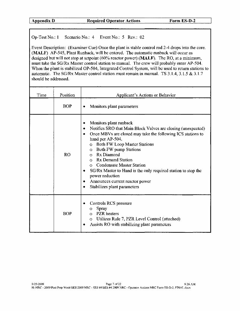
I Appendix D Required Operator Actions Form ES-D-2
Op-Test No.: 1 Scenario No.: 4 Event No.: S Rev.: 02
Event Description: (Examiner Cue) Once the plant is stable control rod 2-4 drops into the core. (MALF) AP-545, Plant Runback, will be entered. The automatic runback will occur as designed but will not stop at setpoint (60% reactor power) (MALF). The RO, at a minimum, must take the SG/Rx Master control station to manual. The crew will probably enter AP-504. When the plant is stabilized OP-S04, Integrated Control System, will be used to return stations to automatic. The SG/Rx Master control station must remain in manual. TS 3.1.4, 3.1.S & 3.1.7 should be addressed.
Time Position Applicant's Actions or Behavior
BOP • Monitors plant parameters
• Monitors plant runback • Notifies SRO that Main Block Valves are closing (unexpected) • Once MBV s are closed may take the following ICS stations to
hand per AP-S04. o Both FW Loop Master Stations o Both FW pump Stations
RO 0 Rx Diamond o Rx Demand Station o Condensate Master Station
• SG/Rx Master to Hand is the only required station to stop the power reduction
• Announces current reactor power • Stabilizes plant parameters
• Controls RCS pressure o Spray
BOP 0 PZR heaters o Utilizes Rule 7, PZR Level Control (attached)
• Assists RO with stabilizing plant parameters
8/25/2009 Page 7 of22 9:26 AM H:\NRC - 2009\Post Prep Week\sES\2009 NRC - SES #4\sES #4 2009 NRC - Operator Actions NRC Form ES-D-2, FINAL.docx

I AppendixD Required Operator Actions Form ES-D-2
Op-Test No.: 1 Scenario No.: 4 Event No.: 5 Rev.: 02
Event Description: (Examiner Cue) Once the plant is stable control rod 2-4 drops into the core. (MALF) AP-545, Plant Runback, will be entered. The automatic runback will occur as designed but will not stop at setpoint (60% reactor power) (MALF). The RO, at a minimum, must take the SGIRx Master control station to manual. The crew will probably enter AP-504. When the plant is stabilized OP-504, Integrated Control System, will be used to return stations to automatic. The SGIRx Master control station must remain in manual. TS 3.1.4, 3.1.5 & 3.1. 7 should be addressed.
Time Position
SRO
CREW
SRO
ROIBOP
Applicant's Actions or Behavior
• Ensures OAC and BOP actions are in progress • Monitors progress via SPDS • Maintains overview of plant conditions and directs plant trip if
limits are closely approached. • Once the plant is stable, holds a mini brief to ensure all crew
members understand plant status • Contacts Work Control to initiate repair efforts
• Diagnose ICS failure • Ifunable to diagnose failure then ICS stations should remain in
hand
• Direct ROIBOP to return ICS stations to automatic lAW OP-504, Integrated Control System
• Addresses TS 3.1.4, Condition A (1 hour to verify SDM) • Addresses TS 3.1.5, Condition A (1 hour to verify SDM) • Addresses TS 3.1.7, Condition A (8 hours to verify API
operable)
• ICS stations are returned to "Auto" in accordance with OP-504 (BOP will normally assist by reading OP-504)
8125/2009 Page 80f22 9:26 AM H:\NRC - 2009\Post Prep WeekISES\2009 NRC - SES #4ISES #4 2009 NRC - Operator Actions NRC Fonn ES-D-2, FINAL.docx

I Appendix D Required Operator Actions Form ES-D-2
Op-Test No.: 1 Scenario No.: 4 Event No.: 6 Rev.: 02
Event Description: (Examiner Cue) After ICS stations are returned to automatic, if applicable, a failure on SCV-12 will cause main generator temperatures to rise. (MALF) The SRO will probably enter AP-51 0, Rapid Power Reduction, to reduce reactor power below the anticipatory reactor trip setpoint (41 % power) and trip the main turbine. AP-660, Turbine Trip, should be concurrently performed. Dependent upon power level and status of ICS stations the SRO may elect to manually trip the reactor when it is determined that cooling water flow can not be restored. This action is allowable and will not detract from the scenario.
Time Position
ROIBOP
Applicant's Actions or Behavior
• Recognize generator main generator temperatures are rising. • Announce/acknowledge alarms
o Event Point 1600 o (0-5-9) Hydrogen Panel Alarm
• Direct SPO to investigate the rising main generator temperatures • Notify SRO of generator temperature rise
• Acknowledges receipt of alarms • Assists RO/BOP in diagnosing failure • Dependent upon the current power level additional power
decrease to trip the turbine may not be needed (OP-701 P&L requires turbine trip if main generator cold gas temperature exceeds 55 degrees.
• Enters AP-51 0, Rapid Power Reduction • Direct RO/BOP actions per AP-510
SRO 0 Adjust Load Rate to desired setpoint o Set Unit Load Demand to "10" o Notify personnel of entry into AP-51O o Maintain PZR Level (Rule 7, attached) o Notify Chemistry of power change o Verify Imbalance within limits o Maintain DFT level between 8 and 11 feet
• Directs BOP to trip the turbine when reactor power is below the anticipatory reactor trip setpoint (41 % power).
8/25/2009 Page 9 of22 9:26 AM H:INRC - 2009\Post Prep Week1SES\2oo9 NRC - SES #4ISES #4 2009 NRC - Operator Actions NRC Fonn ES-0-2, FINAL.docx

I AppendixD Required Operator Actions Form ES-D-2
Op-Test No.: 1 Scenario No.: 4 Event No.: 6 Rev.: 02
Event Description: (Examiner Cue) After ICS stations are returned to automatic, if applicable, a failure on SCV-12 will cause main generator temperatures to rise. (MALF) The SRO will probably enter AP-510, Rapid Power Reduction, to reduce reactor power below the anticipatory reactor trip setpoint (41 % power) and trip the main turbine. AP-660, Turbine Trip, should be concurrently performed. Dependent upon power level and status of ICS stations the SRO may elect to manually trip the reactor when it is determined that cooling water flow can not be restored. This action is allowable and will not detract from the scenario.
Time Position
RO
BOP
Applicant's Actions or Behavior
• Perform actions as directed by the SRO per AP-51O o Adjust Load Rate to desired setpoint o Set Unit Load Demand to "10" o Verify Imbalance within limits o Maintain DFT level between 8 and 11 feet
• Continues power reduction until within the capability of the TBVs ("'=' 20% reactor power)
• Stabilizes plant parameters
• Perform actions as directed by the SRO per AP-510 o Notify personnel of entry into AP-51O o Maintain PZR level (Rule 7, attached) o Notify Chemistry of power change o Maintain DFT level between 8 and 11 feet
• Enters AP-660, Turbine Trip • Direct BOP actions per AP-660
o Depress Main Turbine trip push button o Ensures TVs and GVs are closed o Ensures RCS pressure is stable
SRO 0 Notify personnel of entry into AP-660 o Ensures MS header pressure between 870 and 900 psig o Ensures main generator output breakers are open o Shutdown main generator o Ensures plant conditions stabilize o Maintain PZR level (Rule 7, attached)
8/25/2009 Page 10 of22 9:26 AM H:INRC - 2009\Post Prep Week\sES\2009 NRC - SES #4\SES #4 2009 NRC - Operator Actions NRC Fonn ES-D-2, FINAL.docx

I AppendixD Required Operator Actions Form ES-D-2
Op-Test No.: 1 Scenario No.: 4 Event No.: 6 Rev.: 02
Event Description: (Examiner Cue) After ICS stations are returned to automatic, if applicable, a failure on SCV-12 will cause main generator temperatures to rise. (MALF) The SRO will probably enter AP-510, Rapid Power Reduction, to reduce reactor power below the anticipatory reactor trip setpoint (41 % power) and trip the main turbine. AP-660, Turbine Trip, should be concurrently performed. Dependent upon power level and status ofICS stations the SRO may elect to manually trip the reactor when it is determined that cooling water flow can not be restored. This action is allowable and will not detract from the scenario.
Time Position Applicant's Actions or Behavior
• Perform actions as directed by the SRO per AP-660 o Depress Main Turbine trip push button o Ensure TV sand GV s are closed o Ensure RCS pressure is stable o Notify personnel of entry into AP-660 o Ensure MS header pressure between 870 and 900 psig
BOP 0 Ensure main generator output breakers are open • Breakers 1661 & 1662
o Shutdown main generator • Open field breaker • Select voltage regulator to "OFF"
o Ensure plant conditions stabilize o Maintain PZR level
8/2512009 Page 11 of22 9:26 AM H:\NRC - 2009\Post Prep WeekISES\2009 NRC - SES #4ISES #4 2009 NRC - Operator Actions NRC Fonn ES-D-2, FINAL.docx
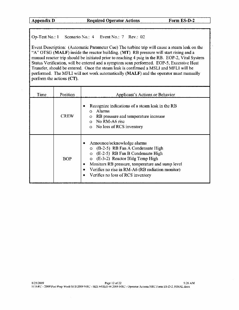
I Appendix D Required Operator Actions Form ES-D-2
Op-Test No.: 1 Scenario No.: 4 Event No.: 7 Rev.: 02
Event Description: (Automatic Parameter Cue) The turbine trip will cause a steam leak on the "A" OTSG (MAL F) inside the reactor building. (MT) RB pressure will start rising and a manual reactor trip should be initiated prior to reaching 4 psig in the RB. EOP-2, Vital System Status Verification, will be entered and a symptom scan performed. EOP-5, Excessive Heat Transfer, should be entered. Once the steam leak is confirmed a MSLI and MFLI will be performed. The MFLI will not work automatically (MALF) and the operator must manually perform the actions (CT).
Time Position Applicant's Actions or Behavior
• Recognize indications of a steam leak in the RB o Alarms
CREW 0 RB pressure and temperature increase o No RM-A6 rise o No loss of RCS inventory
• Announce/acknowledge alarms o (B-2-5) RB Fan A Condensate High o (E-2-5) RB Fan B Condensate High
BOP 0 (E-3-2) Reactor Bldg Temp High • Monitors RB pressure, temperature and sump level • Verifies no rise in RM-A6 (RB radiation monitor) • Verifies no loss of RCS inventory
8125/2009 Page 12 of22 9:26 AM H:\NRC - 2009\Post Prep WeekISES\2009 NRC - SES #4\SES #4 2009 NRC - Operator Actions NRC Form ES-D-2, FINAL.docK

I Appendix D Required Operator Actions Form ES-D-2
Op-Test No.: I Scenario No.: 4 Event No.: 7 Rev.: 02
Event Description: (Automatic Parameter Cue) The turbine trip will cause a steam leak on the "A" OTSG (MALF) inside the reactor building. (MT) RB pressure will start rising and a manual reactor trip should be initiated prior to reaching 4 psig in the RB. EOP-2, Vital System Status Verification, will be entered and a symptom scan performed. EOP-5, Excessive Heat Transfer, should be entered. Once the steam leak is confirmed a MSLI and MFLI will be performed. The MFLI will not work automatically (MALF) and the operator must manually perform the actions (CT).
Time Position Applicant's Actions or Behavior
• Acknowledges receipt of alarms • Assists the RO/BOP in diagnosing the failure • Directs the RO to trip the reactor prior to 4 psig RB pressure • Enters EOP-2, Vital System Status Verification • Direct RO actions per EOP-2
o Depress the Rx trip pushbutton o Verify CRD groups I through 7 are fully inserted o Verify Nls indicate Rx is shutdown
SRO 0 Depress Main Turbine trip pushbutton o Verify TVs and GVs are closed
• Direct formal Symptom Scan with RO and BOP o Check for Station Black Out o Check for Adequate Sub Cooling Margin o Check for Inadequate Heat Transfer o Check for Excessive Heat Transfer o Check for OTSG Tube Rupture
• Directs BOP to determine faulted OTSG and isolate
• When the Rx is tripped, performs EOP-2, Immediate Actions, from memory o Depresses Rx Trip pushbutton o Verifies Groups 1 thru 7 rod inserted
RO 0 Verifies NIs indicate Rx is shutdown o Depress Turbine Trip pushbutton o Verifies all TVs and GVs are closed
• Re-performs EOP-2, Immediate Actions, as directed by SRO
8/2512009 Page 13 of22 9:26 AM H:\NRC - 2009\Post Prep Week\sES\2009 NRC - SES #4\sES #4 2009 NRC - Operator Actions NRC Fonn ES-D-2, FINAL.docx

I AppendixD Required Operator Actions Form ES-D-2
Op-Test No.: 1 Scenario No.: 4 Event No.: 7 Rev.: 02
Event Description: (Automatic Parameter Cue) The turbine trip will cause a steam leak on the "A" OTSG (MALF) inside the reactor building. (MT) RB pressure will start rising and a manual reactor trip should be initiated prior to reaching 4 psig in the RB. EOP-2, Vital System Status Verification, will be entered and a symptom scan performed. EOP-5, Excessive Heat Transfer, should be entered. Once the steam leak is confirmed a MSLI and MFLI will be performed. The MFLI will not work automatically (MAL F) and the operator must manually perform the actions (CT).
Time Position
CREW
BOP
Applicant's Actions or Behavior
• Perform symptom scan o Station Blackout o Inadequate SCM o Inadequate Heat Transfer o Excessive Heat Transfer o SG Tube Rupture
• Determine that Excessive Heat Transfer symptom exists and enters EOP-5, Excessive Heat Transfer
• Recognize that Rule 2, HPI Control and Rule 3, EFW Control are in effect (attached)
• Depresses Global Silence pushbutton • Isolates the "A" OTSG (CT) • Recognizes that MFLI did not occur and performs the following: o Selects close FWV-3l (block valve) o Selects close FWV-30 (block valve) o Selects close FWV-36 (block valve) o Selects close FWV -28 (cross-tie valve) o Selects close FWV -14 (MFWP suction valve) o Trips FWP-2A (MFWP)
• Notifies SRO ofMFLI automatic isolation failure
8/25/2009 Page 14 of22 9:26 AM H:INRC - 2009\Post Prep Week\SES\2009 NRC - SES #4\sES #4 2009 NRC - Operator Actions NRC Form ES-D-2, FINAL.docx

I Appendix D Required Operator Actions Form ES-D-2
Op-Test No.: 1 Scenario No.: 4 Event No.: 8 Rev.: 02
Event Description: (Automatic Parameter Cue) EFIC will actuate from the HPI signal. The operator will recognize excessive EFW flow to the "A" OTSG through EFV-58. Rule 3 will be in effect and the operator will attempt to isolate flow by taking EFIC to manual and closing EFV -14 (block valve). The block valve will stroke partially in the closed direction and then the motor power fuse will blow. [MALF] The operator must secure EFP-3 (eT) to stop EFW flow to the OTSG.
Time Position Applicant's Actions or Behavior
• Enters EOP-5, Excessive Heat Transfer • Direct ROIBOP actions per EOP-5
o Isolate affected OTSGs • Depress MSLI and MFLI push buttons • Ensure FW sources and leak paths are closed • If any affected EFIC control valve fails to close then
select Manual Permissive and close the associated block valve. • EFV-58 (A train, A OTSG control valve) • EFV-14 (A train, A OTSG block valve)
o Ensure ES equipment is properly aligned • IfRBIC has actuated and adequate SCM exists, then stop
SRO all RCPs o Maintain PZR level (Rule 7, attached) o Notify personnel of entry into EOP-5 o IfRCS temp remains < 5320 F then start RCS boration o Ensure proper MSLI and MFLI o Notify Chemistry to sample for tube leakage o Verify proper CC cooling o Ensure level in available OTSG trending to correct level o Minimize RCS temperature changes o Minimize RCS pressure changes o Verify OTSG tube leakage.:::: 1 gpm o Ensure MSR HP bundle isolation valves are closed o Bypass ES if permit exists o Maintain minimum adequate SCM
8/25/2009 Page 15 of22 9:26 AM H:INRC - 2009\Post Prep Week\sES\2009 NRC - SES #4\sES #4 2009 NRC - Operator Actions NRC Fonn ES-D-2, FINAL.docx

I Appendix D Required Operator Actions Form ES-D-2
Op-Test No.: 1 Scenario No.: 4 Event No.: 8 Rev.: 02
Event Description: (Automatic Parameter Cue) EFIC will actuate from the HPI signal. The operator will recognize excessive EFW flow to the "A" OTSG through EFV-58. Rule 3 will be in effect and the operator will attempt to isolate flow by taking EFIC to manual and closing EFV -14 (block valve). The block valve will stroke partially in the closed direction and then the motor power fuse will blow. [MALF] The operator must secure EFP-3 (CT) to stop EFW flow to the OTSG.
Time Position
ROIBOP
Applicant's Actions or Behavior
• Performs Rule 3, EFW/AFW Control o Attempts to close EFV-58 (A train, A OTSG control
valve) • Determines that EFW flow is not controlled and depresses
"Manual Permissive" on both channels o Selects close EFV-14 (A train, A OTSG block valve)
• Recognizes that EFV -14 did not fully close o Amber light only o Flow indication on EF-25-FIl
• Requests permission from SRO to secure EFP-3 • Secures EFP-3 (CT) • Ensure ES equipment is properly aligned
o If RBIC has actuated and adequate SCM exists, then stop all RCPs
• Maintain PZR level (Rule 7, attached) • Notifies personnel of entry into EOP-5 • IfRCS temp remains < 5320 F then start RCS boration • Ensures proper MSLI and MFLI • Notify Chemistry to sample for tube leakage • Verify proper CC cooling • Minimizes RCS temperature changes • Minimizes RCS pressure changes • Verifies OTSG tube leakage:: 1 gpm • Ensures MSR HP bundle isolation valves are closed • Maintains minimum adequate SCM
o PZR Spray o PORV
8/25/2009 Page 16 of22 9:26 AM H:INRC - 2009\Post Prep WeeklSES\2oo9 NRC - SES #4ISES #4 2009 NRC - Operator Actions NRC Fonn ES-D-2, FINAL.docx

I AppendixD Required Operator Actions Form ES-D-2
Op-Test No.: I Scenario No.: 4 Event No.: 9 Rev.: 02
Event Description: (Automatic Parameter Cue) When the ES actuation occurs MUV-73 will not open from the MCB. (MALF) The operator must monitor MUT level and either have MUV-73 manually opened in the field or secure MUP-IB (CT) prior to the MUT going empty.
Time Position
SRO
ROIBOP
Applicant's Actions or Behavior
• Directs the ROIBOP to ensure all ES equipment is properly aligned
• Performs Rule 2, HPI Control (attached) • Verifies all ES components are operating via the actuation light
indications (green) for ES actuated equipment. o Recognizes MUV-73 still closed (BWST suction valve for
MUP-iB) o Attempts to open MUV -73 manually o Recognizes MUP-IC is not running o Starts MUP-IC o Notifies SRO of malfunction with MUV -73 and MUP-I C o Directs PPO to manually open MUV -73 o Monitors MUT level
• Secures MUP-IB, opens MUV-73 (or opens MUV-62) prior to loss of suction (CT)
Scenario may be terminated any time after actions to minimize subcooling margin have been taken.
8/25/2009 Page 17 of22 9:26 AM H:INRC - 2009\Post Prep Week\sES\2009 NRC - SES #4\SES #4 2009 NRC - Operator Actions NRC Form ES-D-2, FINAL.docx

I Appendix D Required Operator Actions Form ES-D-2
RULE 1, LOSS OF SCM
• _ IF < 1 min has elapsed since losing adequate SCM, THEN immediately stop all RCPs.
• _ IF RCPs were NOT stopped within 1 min, THEN ensure all operating RCPs remain running until any of the following exist:
SCM is restored
_ LPI flow > 1400 gpm in each injection line.
• _ Manually actuate ES.
• Depress "ISCM" push buttons for EFIC channels A and B.
• Ensure Tincore is selected on SPDS.
• _ Progress toward a maximum plant cooldown to achieve CFT and LPI flow as soon as possible.
• _ Depress "HPI MAN ACT" push buttons on Trains A and B .
• _ Depress "RB ISO MAN ACTUATION" push buttons on Trains A and B.
• _!E LPI has NOT actuated, AND RCS PRESS ~ 300 psig, THEN depress "LPI MAN ACT" push buttons on Trains A and B.
812512009 Page 18 of22 9:26 AM H:\NRC - 2009\Post Prep Week\sES\2009 NRC - SES #4\sES #4 2009 NRC - Operator Actions NRC Fonn ES-D-2, FINAL.docx
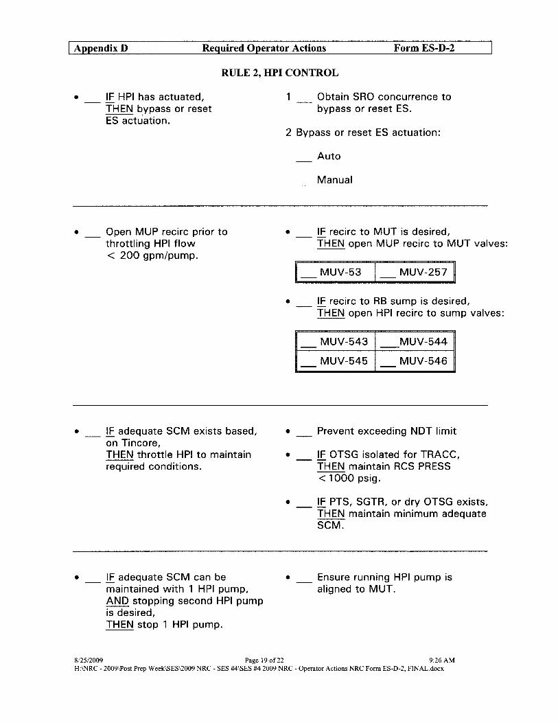
I Appendix D Required Operator Actions Form ES-D-2
RULE 2, HPI CONTROL
• _ !E HPI has actuated, THEN bypass or reset ES actuation.
• Open MUP recirc prior to throttling HPI flow < 200 gpm/pump.
• _ !E adequate SCM exists based, on Tincore, THEN throttle HPI to maintain required conditions.
• _ !E adequate SCM can be maintained with 1 HPI pump, AND stopping second HPI pump is desired, THEN stop 1 HPI pump.
1 Obtain SRO concurrence to bypass or reset ES.
2 Bypass or reset ES actuation:
Auto
Manual
• _ !E recirc to MUT is desired, THEN open MUP recirc to MUT valves:
1_ MUV-53 1_ MUV-257 ~
• _ !E recirc to RB sump is desired, THEN open HPI recirc to sump valves:
MUV-543 MUV-544 - --MUV-545 MUV-546 - -
• _ Prevent exceeding NDT limit
• _ !E OTSG isolated for TRACC, THEN maintain RCS PRESS --< 1000 psig.
• _ !E PTS, SGTR, or dry OTSG exists, THEN maintain minimum adequate SCM.
• _ Ensure running HPI pump is aligned to MUT.
812512009 Page 19 of22 9:26 AM H:\NRC - 2009\Post Prep Week\sES\2009 NRC - SES #4\sES #4 2009 NRC - Operator Actions NRC Form ES-D-2, FINAL.docx

I Appendix D Required Operator Actions Form ES-D-2
RULE 3, EFW/AFW CONTROL
• Ensure available OTSGs are at or trending toward required level.
• IF manual control of EFW flow is desired, THEN establish manual EFIC control.
• _ i.E adequate SCM does NOT exist, AND level in available OTSGs is NOT at or trending toward "ISCM" level, THEN establish manual required flow.
• _ i.E adequate SCM exists, THEN throttle flow to prevent OTSG PRESS from lowering > 100 psig below desired PRESS.
"LLL" > 20in
"NAT CIRC" > 70%
"ISCM" > 90%
1 _ Obtain SRO concurrence to place EFIC in manual.
2 _ Control EFW to maintain required EFW flow and OTSG level.
3 _ i.E EFW flow is NOT controlled, THEN depress EFIC channels
EFW
AFW
A and B "MANUAL PERMISSIVE" push buttons and close affected EFW block valve.
2 OTSGs > 280 gpm in 1 line to each OTSG
10TSG > 470 gpm in 1 line to 1 OTSG
20TSGs > 250 gpm to < 300 gpm/OTSG
10TSG > 450 gpm to < 600 gpm
• Do not allow OTSG level to lower.
8/2512009 Page 20 of22 9:26 AM H:\NRC - 2009\Post Prep Week\sES\2009 NRC - SES #4\sES #4 2009 NRC - Operator Actions NRC Fonn ES-D-2, FINAL.docx
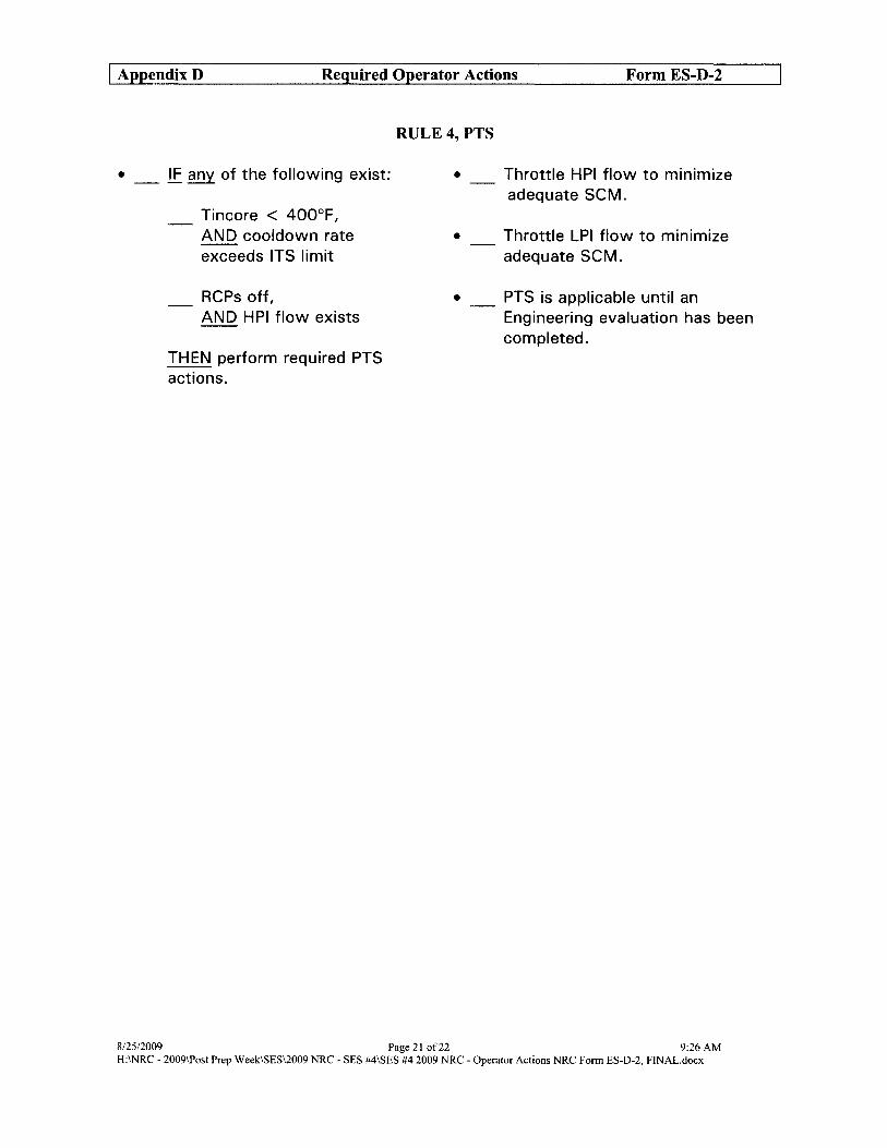
I Appendix D Required Operator Actions Form ES-D-2
• _ IF any of the following exist:
Tincore < 400°F, AND cool down rate exceeds ITS limit
RCPs off, AND HPI flow exists
THEN perform required PTS actions.
RULE4,PTS
•
•
•
Throttle HPI flow to minimize adequate SCM.
Throttle LPI flow to minimize adequate SCM.
PTS is applicable until an Engineering evaluation has been completed.
8/25/2009 Page 21 of22 9:26 AM H:\NRC - 2009\Post Prep Week\sES\2009 NRC - SES #4\sES #4 2009 NRC - Operator Actions NRC Fonn ES-D-2, FINAL.docx

I AppendixD Required Operator Actions Form ES-D-2
RULE 7, PZR LEVEL CONTROL
1 IF PZR level is < PZR level band,
2
3
THEN restore PZR level.
!E PZR level does NOT recover, THEN establish manual HPI flow.
!E PZR level recovers, THEN restore normal PZR conditions.
[Rule 2, HPI Control]
PZR Level Band
Rx at power> 20% 200 in to 240 in
Rx at power :s 20% 1 20 in to 200 in
Rx tripped 50 in to 1 20 in
• Cycle appropriate BWST to MUP valve to maintain MUT level 2: 55 in:
1_ MUV-73 1_ MUV-58
• Close MUV-49
1 _ Open MUV-24
2 _ Notify SSO to evaluate Emergency Plan entry.
3 _ !E PZR level does NOT recover, THEN start second MUP and required cooling pumps.
[Rule 5, Diesel Load Control]
4 _ !E PZR level does NOT recover, THEN open additional HPI valves.
5 _ IF PZR level does NOT recover, THEN close MUP to MUT recircs:
1_ MUV-53 1_ MUV-257I
• _ !E letdown is desired, THEN CONCURRENTLY PERFORM EOP-14, Enclosure 4, Letdown Recovery (if accessible).
8/25/2009 Page 22 of 22 9:26 AM H:INRC - 2009\Post Prep Week\sES\2009 NRC - SES #4\sES #4 2009 NRC - Operator Actions NRC Form ES-D-2, FINAL.docx
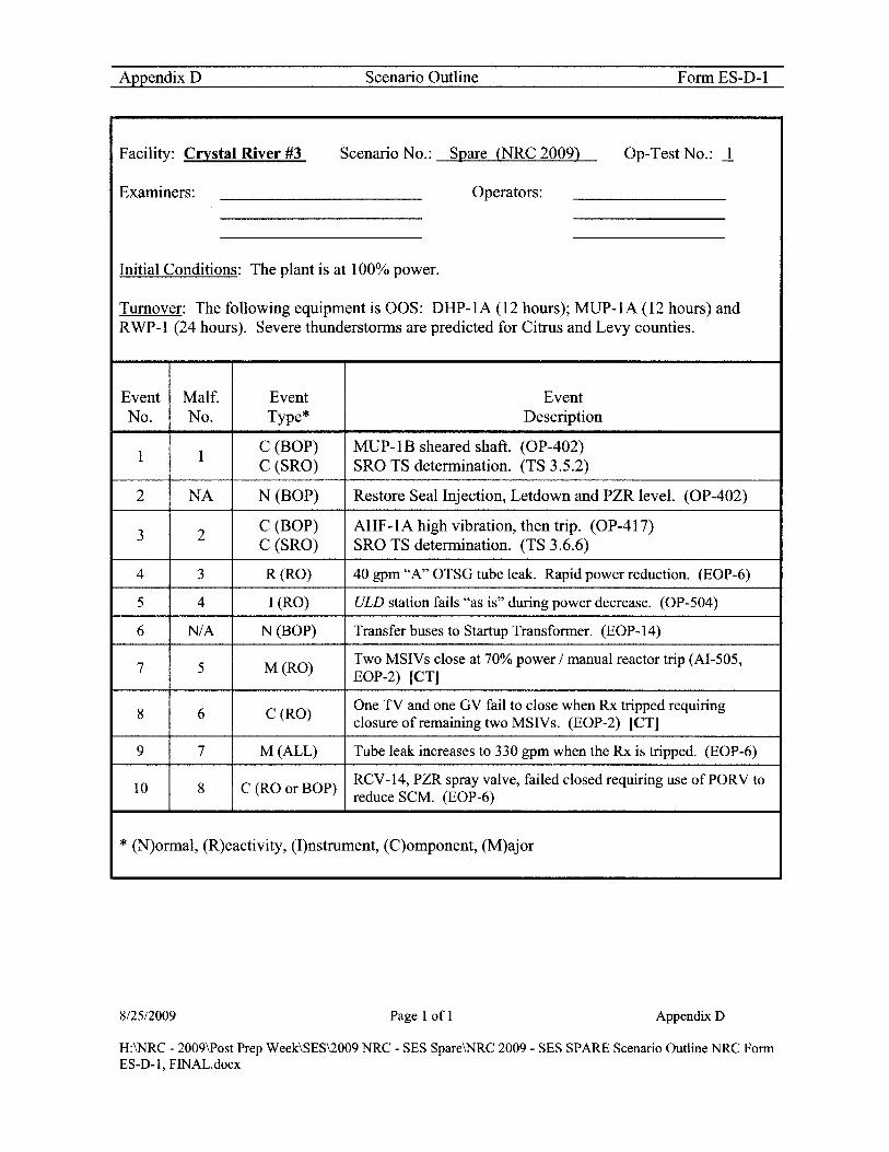
AppendixD Scenario Outline Form ES-D-I
Facility: Crystal River #3 Scenario No.: Spare (NRC 2009) Op-TestNo.: ~
Examiners: Operators:
Initial Conditions: The plant is at 100% power.
Turnover: The following equipment is OOS: DHP-IA (12 hours); MUP-IA (12 hours) and RWP-I (24 hours). Severe thunderstorms are predicted for Citrus and Levy counties.
Event Malf. Event Event No. No. Type* Description
I I C (BOP) MUP-IB sheared shaft. (OP-402) C (SRO) SRO TS determination. (TS 3.5.2)
2 NA N (BOP) Restore Seal Injection, Letdown and PZR level. (OP-402)
3 2 C (BOP) AHF-IA high vibration, then trip. (OP-417) C (SRO) SRO TS determination. (TS 3.6.6)
4 3 R(RO) 40 gpm "A" OTSG tube leak. Rapid power reduction. (EOP-6)
5 4 I (RO) ULD station fails "as is" during power decrease. (OP-504)
6 N/A N (BOP) Transfer buses to Startup Transformer. (EOP-14)
7 5 M(RO) Two MSIVs close at 70% power I manual reactor trip (AI-505, EOP-2) [CT]
8 6 C(RO) One TV and one GV fail to close when Rx tripped requiring closure of remaining two MSIVs. (EOP-2) lCT]
9 7 M (ALL) Tube leak increases to 330 gpm when the Rx is tripped. (EOP-6)
10 8 C (RO or BOP) RCV-14, PZR spray valve, failed closed requiring use ofPORV to reduce SCM. (EOP-6)
* (N)ormal, (R)eactivity, (I)nstrument, (C)omponent, (M)ajor
8125/2009 Page 1 of 1 Appendix D
H:\NRC - 2009\Post Prep Week\SES\2009 NRC - SES Spare\NRC 2009 - SES SPARE Scenario Outline NRC Fonn ES-D-I, FINAL.docx

Narrative Summary NRC 2009 Spare Scenario
Plant is initialized at 100% power. Severe thunderstorms are predicted for Citrus and Levy counties.
Soon after turnover is complete MUP-IB will experience a sheared shaft. OP-402, Makeup and Purification System, will be used to start MUP-l C. Section 4.6, System Restoration after MU Pump Trip, is a much easier section to use for this failure, however use of Section 4.5, MU Pump Transfer, is allowable. The crew should start MUP-IC and restore PZR level, Seal Injection and Letdown. ITS 3.5.2, Condition A, should be addressed.
After the plant has been stabilized AHF -1 A will experience high vibration due to a failing bearing. The fan will trip after one minute if not already secured. TS 3.6.6, Condition C, will be entered. OP-417, Containment Operating Procedure, will be used to select AHF-IC for ES start.
After AHF-IC is selected for ES start and TS actions are addressed a 36 gpm SGTR develops on the "A" OTSG. Crew diagnoses the tube leak using MS line monitor increase, RM-AI2 indication and RCS leak rate determination. EOP-6 will be entered and a power reduction commenced.
At approximately 95% power ULD station output will fail "as is". The RO will diagnose the problem and receive permission from the SRO to lower power in manual using the SGIRX master station.
At approximately 70% power two MSIV s close (opposite OTSGs). A manual reactor trip is required per AI-505 (CT). Immediate actions of EOP-2 are performed. During the Immediate Actions, one TV and one GV will be found open. The RO will have to close the remaining two MSIVs (CT). The Immediate Actions will then be verified and a symptom scan performed. Due to the trip the SGTR increases to "" 330 gpm. After the symptom scan is performed the SRO should return to the beginning of EOP-6 and start a plant cooldown and depressurization.
Since all MSIVs are closed TBVs are lost requiring steaming to atmosphere. Emergency Plan upgrade should be recognized but classification is not required.
When RCS depressurization is attempted RCV-14 (spray valve) fails to open. Crew should use the PORV to decrease subcooling margin.
The scenario may be terminated when SCM is minimized and a plant cooldown has commenced.
8125/2009 Page 1 of6 9:25 AM
H:\NRC - 2009\Post Prep Week\SES\2009 NRC - SES Spare\NRC 2009 SES Spare Summary - Turnover FINAL.docx

Procedures used: (ARs not listed)
OP-402 AP-SlO EOP-2 OP-417 EOP-6 OP-S04 AI-SOS EOP-13
EOP-14
Target Quantitative Attributes - Spare Scenario - NRC 2009 Actual Attributes
1. Total Malfunctions (S-8) 8
2. Malfunctions after EOP entry (1-2) 2
3. Abnormal Events (2-4) 2
4. Major Transients (1-2) 1
S. EOPs entered requiring substantive actions (1-2) 1
6. EOP contingencies requiring substantive actions (0-2) 1
7. Critical Task (2-3) 2
812512009 Page 2 of6 9:25AM
H:\NRC - 2009\Post Prep Week\SES\2009 NRC - SES Spare\NRC 2009 SES Spare Summary - Turnover FINAL.docx

SHIFT TURNOVER
A. Initial Conditions:
1. Time in core life - 300 EFPD 2. Shift: [X] Day [] Night 3. Rx power and power history - 100% for 40 days 4. Boron concentration - 992 ppmb 5. Xenon - Equilibrium @ -2.4% M<IK 6. RCS Activity - See Status Board 7. EOOS condition: Yellow 8. Protected Train - B
B. Tech. Spec. Action requirement(s) in effect:
• TS 3.5.2, Condition A, for DHP-1A. Condition entered 12 hours ago. • TS 3.3.17, Condition A, Function 23, for LPI Pump Run Status lights.
Condition entered 12 hours ago. • Fire Protection Plan, Table 6.9A, for MUP-1A
C. Clearances in effect:
• DHP-1A for breaker fuse block replacement. Expected return to service in 4 hours.
• MUP-1A shaft replacement due to high vibration. Expected return to service in 24 hours.
• RWP-l for impellor replacement. Expected return to service in 4 hours.
D. Significant problems/abnormalities:
• Severe thunderstorms are predicted for Citrus and Levy counties.
E. Evolutions/maintenance for the on-coming shift:
• Continue power operations. • Maintenance to continue work on DHP-1A, MUP-1A and RWP-l.
F. CRS - Instruct the ROs to walk down the main control board.
G. Required Emergency Plan Implementation
8125/2009
[ ] Full Implementation, including all required notifications. [ ] Initial/upgrade classifications - internal notifications. [X] None
Page 3 of6 9:25AM
H:\NRC - 2009\Post Prep Week\SES\2009 NRC - SES Spare\NRC 2009 SES Spare Smnmary - Turnover FINAL.docx

Examination SetuplExecution Spare Scenario
INITIAL CONDITIONS
A. "Restore" the simulator to IC#_---"'3"""1 __ developed/or this SES.
B. "Unfreeze" the simulator and perform the following:
1. Start RWP-2A running 2. Stop RWP-l
C. "Freeze" the simulator and enter Exam 4 lesson plan directory.
1. "Start" Lesson Plan SES Spare NRC-2009
D. "Unfreeze" the simulator and "Trigger" Setup Step(s) which will:
See Simulator lesson plan
E. Tag out the following equipment:
1. Place CIT on DHP-IA CIS in Normal After Stop 2. Place CIT on MUP-IA CIS in Normal After Stop 3. Place CITs on MUP-2A & 3A CIS in Normal After Stop 3. Place CITs on MUP-4A & 5A CIS in Stop 4. Place CIT on RWP-l CIS in Normal After Stop
F. Additional Modifications required to the IC.
1. Ensure SPDS selected to NORMIIMB and history traces cleared and history trace selected. Also ensure "A" and "B" SPDS are properly selected for RCS Loops and Primary instruments selected.
2. Ensure SPDS on CNO/SSO/ST A computers displaying correct data for IC.
3. Ensure Group 59 indicative of current reactor power.
4. Acknowledge computer and annunciator alarms.
5. Ensure proper PICS groups displayed on overhead screens.
G. Freeze the simulator and notify the lead examiner.
RESTORE AHF-1C "COOLING WATER ISOLATED" AND "ES SELECTED" TAGS 8/2512009 Page 4 of6 9:25AM
H:\NRC - 2009\Post Prep Week\SES\2009 NRC - SES Spare\NRC 2009 SES Spare Summary - Turnover FINAL.docx

Booth Operator Actions NRC 2009 Spare Scenario
START DATA RECORDER
A. EVENT #1 When directed input the MUP-lB failure. [Trigger Step #1: MUP-IB sheared shaft]
Role Play: When directed as PPO to energize MUV -62 and MUV -69 wait two minutes, then trigger Step 2 and report back to control room that the breakers are closed. [Trigger Step #2: Instructor Action - Energize MUV-62 and MUV-69]
B. EVENT #2 - Normal Evolution
c. EVENT #3 When directed input the AHF-IA failure. [Trigger Step #3: AHF-IA high vibration - trips in one minute if not secured]
Role Play: When directed as PPO manipulate SW valves and report back to control room.
D. EVENT#4 When directed initiate the ~40 gpm "A" SGTR. [Trigger Step #4: "A" OTSG Tube Leak, 40 gpm]
E. EVENT #5 When directed or at 95% power ULD demand fails "as is". [Trigger Step #5: ULD demand fails "as is"] NOTE: ULD demandfailure is setfor 95% power. Iffailure is input more than 2%from expected (95% power) then failure value must be adjusted to new power level prior to input.
F. EVENT #6 - Normal evolution Transfer buses to SVT. No booth actions.
G. EVENTS #7, #8 & #9 When directed or at 70% power two MSIV s close requiring a manual reactor trip. One TV and one GV will not close following the turbine trip. Tube leak increases to ~330 gpm. [Trigger Step #6: Two MSIVs close, tube leak increases to 330 gpm, one TV and one GV fail to close]
812512009 Page 5 of6 9:25 AM
H:\NRC - 2009\Post Prep Week\SES\2009 NRC - SES Spare\NRC 2009 SES Spare Summary - Turnover FINAL.docx

H. EVENT #10 When crew attempts to open RCV -14 to minimize SCM RCV -14 will not open. Crew will have to use the PORV to control SCM.
Note: RCV-14 failure is conditional based on Rx power and was triggered during the setup step.
Role Play: If contacted as the SPO to perform EOP-14 Enclosure 1 wait ~23 minutes and report completion. (Open Lesson Plan: Misc\Enc_l.lsn, execute and trigger]
Role Play: If contacted as the PPO to perform EOP-14 Enclosure 2 wait ~ 15 minutes and report completion. (Open Lesson Plan: Misc\Enc_2.lsn, execute and trigger]
8/25/2009 Page 6 of6 9:25 AM
H:\NRC - 2009\Post Prep Week\SES\2009 NRC - SES Spare\NRC 2009 SES Spare Summary - Turnover FINAL.docx

I Appendix D Required Operator Actions Form ES-D-2
Op-Test No.: I Scenario No.: Spare Event No.: 112 Rev.: 0
Event Description: (Examiner Cue) Soon after turnover is complete MUP-IB will experience a sheared shaft. (MALF) OP-402, Makeup and Purification System, will be used to start MUP-I C. Section 4.6, System Restoration after MU Pump Trip, is a much easier section to use for this failure, however use of Section 4.5, MU Pump Transfer, is allowable. The crew should start MUP-IC and restore PZR level, Seal Injection and Letdown. ITS 3.5.2, Condition B, should be addressed.
Time Position
BOP
SRO
8125/2009
Applicant's Actions or Behavior
• Announce/acknowledge alarms o (B-6-2) Makeup PP B Gear Oil Press Low o (H-5-7) RC Pump Seal Flows High/Low
• Informs SRO of the following: o Auto-start ofMUP-5B o Low current indication on MUP-IB (::::: 30%) o Seal injection flow indication at 0 gpm o Makeup flow indication at 0 gpm
• Acknowledges receipt of alarms • Directs BOP to secure MUP-IB • May direct BOP to isolate letdown • May direct BOP to have DC knife switch for MUP-IB opened • Directs BOP to start MUP-IC IA W OP-402, Makeup and
Purification System • Addresses TS 3.5.2, Condition B, and declares MUP-IB
inoperable (72 hours to repair)
Page 1 of25 Appendix D
H:\NRC - 2009\Post Prep Week\SES\2009 NRC - SES Spare\NRC 2009 SES Spare Operator Actions NRC Fonn ES-D-2, FlNAL.docx

I Appendix D Required Operator Actions Form ES-D-2
Op-Test No.: 1 Scenario No.: Spare Event No.: 112 Rev.: 0
Event Description: (Examiner Cue) Soon after turnover is complete MUP-1B will experience a sheared shaft. (MALF) OP-402, Makeup and Purification System, will be used to start MUP-1 C. Section 4.6, System Restoration after MU Pump Trip, is a much easier section to use for this failure, however use of Section 4.5, MU Pump Transfer, is allowable. The crew should start MUP-1C and restore PZR level, Seal Injection and Letdown. ITS 3.5.2, Condition B, should be addressed.
Time Position Applicant's Actions or Behavior
• Performs OP-402, Section 4.6 o Closes MUV -16 (Seal Injection control valve) o Closes MUV-31 (PZR level control valve) o Closes MUV-50 (letdown control valve) o Closes MUV-51 (letdown control valve) o Observes RCP parameters o Directs the PPO to energize MUV -62 and MUV -69 o Closes MUV-58 (BWST to MUP-1C iso valve) o Closes MUV -69 (MUP cross-tie valve) o Opens MUV -62 (MUP cross-tie valve) o Opens MUV-73 (BWST to MUP-1B iso valve) o Starts MUP-4C (MUP-1C gear oil pump) o Starts DCP -1 B (cooling water pump)
BOP o Starts RWP-3B (cooling water pump) o Starts MUP-IC o Places MUP-4C to auto o Restores makeup and letdown flow
• Places MUV-31 in auto • Performs section 4.l5 (attached)
o Slowly re-establishes Seal Injection flow • Throttle MUV -16 to obtain 12 gpm over 2 minutes • Ensure CBO valves open (MUV-253, 258, 259, 260 &
261) • Throttle MUV -16 to obtain 24 gpm • Throttle MUV-16 to obtain 36 gpm • Place MUV -16 in auto
o Directs the PPO to de-energize MUV -62 and MUV -69 o Notifies SRO to review Tech Specs
8125/2009 Page 2 of25 AppendixD
H:\NRC - 2009\Post Prep Week\SES\2009 NRC - SES Spare\NRC 2009 SES Spare Operator Actions NRC Form ES-D-2, FINAL.docx

I Appendix D Required Operator Actions Form ES-D-2
Op-Test No.: I Scenario No.: Spare Event No.: 112 Rev.: 0
Event Description: (Examiner Cue) Soon after turnover is complete MUP-IB will experience a sheared shaft. (MALF) OP-402, Makeup and Purification System, will be used to start MUP-1 C. Section 4.6, System Restoration after MU Pump Trip, is a much easier section to use for this failure, however use of Section 4.5, MU Pump Transfer, is allowable. The crew should start MUP-IC and restore PZR level, Seal Injection and Letdown. ITS 3.5.2, Condition B, should be addressed.
Time
8125/2009
Position Applicant's Actions or Behavior
• Once the plant is stable, holds a mini brief to ensure all crew members understand plant status
SRO • Contacts Work Control to initiate repair efforts • May review the SRO checklist for unplanned equipment status
changes
Page 3 of25 Appendix D
H:\NRC - 2009\Post Prep Week\SES\2009 NRC - SES Spare\NRC 2009 SES Spare Operator Actions NRC Fonn ES-D-2, FINAL.docx

I Appendix D Required Operator Actions Form ES-D-2
Op-Test No.: 1 Scenario No.: Spare Event No.: 3 Rev.: 0
Event Description: (Examiner Cue) After the plant has been stabilized AHF-IA will experience high vibration due to a failing bearing [MALF]. The fan will trip after one minute if not already secured. TS 3.6.6, Condition C, will be entered. OP-417, Containment Operating Procedure, will be used to select AHF-IC for ES start.
Time
8125/2009
Position Applicant's Actions or Behavior
• Announce/acknowledge alarms o (B-2-4) "RB Fan A Vibration High"
BOP o Reviews AR-302
• Notifies SRO of malfunction • May attempt to reset alarm • May recommend securing fan
• May direct BOP to secure AHF-IA • Directs BOP to start AHF -1 C using OP -417 • Enters TS 3.6.6, Condition C, for one required containment
SRO cooling train inoperable (7 days to restore) • Contacts Work Control to initiate repair efforts • May review SRO checklist for unplanned equipment status
change
• Uses OP-417, Section 4.7, to perform the following: o Notifies PPO to seal closed SWV-36 (field action) o Selects AHF-IC using the "RB Fan ES A Select" switch in
ES Act Relay Cabinet 4D BOP 0 Notifies SRO to review TS 3.6.6
o Notifies PPO to seal open SWV-I05 (field action) o Ensures open SWV-39 and SWV-45 (cooling water inlet and
outlet valves) o Starts AHF-IC
Page 4 of25 Appendix D
H:\NRC - 2009\Post Prep Week\SES\2009 NRC - SES Spare\NRC 2009 SES Spare Operator Actions NRC Fonn ES-D-2, FINAL.docx

I AppendixD Required Operator Actions Form ES-D-2
Op-Test No.: I Scenario No.: Spare Event No.: 4 Rev.: 0
Event Description: (Examiner Cue) After AHF -I C is selected for ES start and TS actions are addressed a 36 gpm SGTR develops on the "A" OTSG [MALF]. Crew diagnoses the tube leak using MS line monitor increase, RM-AI2 indication and RCS leak rate determination. EOP-6 will be entered and a power reduction commenced.
Time Position
BOP
RO
SRO
8125/2009
Applicant's Actions or Behavior
• Announce/acknowledge alarms o (H-I-5) "MN Stm Line AlB High Rad Monitor Fail"
• Diagnoses OTSG tube leak o RM-G27 in HilHi alarm o Mismatch between makeup and letdown o SPDS shows RM-G27 at 100 GPD o Monitors RM-AI2
• Perform leak rate calculation
• Assists BOP with diagnosing tube leak • Monitors SPDS • Verifies PZR level is being maintained • Performs backup leak calculation
• Assist ROIBOP in diagnosing the tube leak. • Enters EOP-06 ifleakage is reported> I GPM and directs
RO/BOP actions o Maintains PZR level, Rule 7 (attached) o Directs adjustment oflCS load rate o Directs adjustment of Unit Load Master to 10 o Directs RO to trip Rx if PZR level goes < 100" o Direct BOP to make a PA announcement, inform SPOIPPO
ofEOP-06 entry o Verifies affected OTSG o Directs closure ofMSV-55 (A OTSG steam to EFP-2)
• Recognize E-plan entry conditions are met (not required to classify at this time)
Page 5 of25 Appendix D
H:\NRC - 2009\Post Prep Week\SES\2009 NRC - SES Spare\NRC 2009 SES Spare Operator Actions NRC-Fonn ES-D-2, FINAL.docx

I Appendix D Required Operator Actions Form ES-D-2
Op-Test No.: 1 Scenario No.: Spare Event No.: 4 Rev.: 0
Event Description: (Examiner Cue) After AHF -1 C is selected for ES start and TS actions are addressed a 36 gpm SGTR develops on the "A" OTSG [MALF]. Crew diagnoses the tube leak using MS line monitor increase, RM-AI2 indication and RCS leak rate determination. EOP-6 will be entered and a power reduction commenced.
Time Position Applicant's Actions or Behavior
• Perform actions as directed by the SRO per EOP-6
BOP o Make PA announcement, inform SPOIPPO of EOP-06 entry o Verifies affected OTSG
• Closes MSV-55 (A OTSG steam to EFP-2)
• Perform actions as directed by the SRO per EOP-6 o Maintains PZR level, Rule 7 (attached) o Adjusts of ICS load rate
RO
o Adjusts Unit Load Master to 10
8125/2009 Page 6 of25 Appendix D
H;\NRC - 2009\Post Prep Week\SES\2009 NRC - SES Spare\NRC 2009 SES Spare Operator Actions NRC Form ES-D-2, FINAL.docx

I AppendixD Required Operator Actions Form ES-D-2
Op-Test No.: 1 Scenario No.: Spare Event No.: 5/6 Rev.: 0
Event Description: (Examiner Cue) Power reduction is started per EOP-6. Initially the ULD station will be used for the power reduction. The ULD station output will fail "as is" at approximately 95% power [MALF]. The RO will diagnose the problem and receive permission from the SRO to decrease power in manual using the SG/RX master station. BOP will transfer Unit buses to the Startup Transformer.
Time
8/25/2009
Position Applicant's Actions or Behavior
• Directs ROIBOP actions IA W EOP-6 • Assists RO in diagnosing ULD failure • Directs RO to continue the power reduction with the SGIRX
Master in Hand o When power is < 80% notify SPO to ensure MS is supplying
SRO AS
RO
BOP
o Maintain DFT level between 8 and 11 feet o Verify Aux Transformer is not supplying any bus
• Directs BOP to perform EOP-14, Enclosure 23 o Concurrently performs EOP-14, Enclosure 17
• Perform actions as directed by the SRO per EOP-6 • At approximately 95% power recognizes power reduction is not
in progress when plant quits responding • Informs the SRO of failure • Takes SGIRX master to hand and continue power reduction • Monitors
oRCS Tave o "A" and "B" FW flows o Turbine SetterlReference
• Maintains DFT level between 8 and 11 feet
• Performs EOP-14, Enclosure 23 o Selects AUTO Transfer switches for breakers 3103, 3203,
3104 and 3204 to Manual o Closes breaker 3103/ opens breaker 310 1 o Closes breaker 3203/opens breaker 3201 o Closes breaker 3104/ opens breaker 3102 o Closes breaker 3204/opens breaker 3202
Page 7 of25 AppendixD
H:\NRC - 2009\Post Prep Week\SES\2009 NRC - SES Spare\NRC 2009 SES Spare Operator Actions NRC Fonn ES-D-2, FINAL.docx

I AppendixD Required Operator Actions Form ES-D-2
Op-Test No.: 1 Scenario No.: Spare Event No.: 7/8/9 Rev.: 0
Event Description: (Examiner Cue) At approximately 70% power 2 MSIV s close [MT] which requires a manual reactor trip (CT). The SGTR increases to approximately 330 gpm (triggered by the reactor trip). When the Rx is tripped, one TV and one GV do not close, [MALF] requiring the closure of the remaining two MSIVs. (CT) Plant cooldown commences per EOP-6. TBVs are unavailable due to MSIV closure.
Time Position
RO
8125/2009
Applicant's Actions or Behavior
• Announces and responds to alarms o (H-5-3) "Main Steam Iso Vlv Air Failure" o SVlISV2 lights flashing intermittently
• Announce MSIV closures as they occur • Manually trips the reactor due to the closure of 2 MSIVs
(CT) • Performs Immediate Actions of EOP-2 from memory
o Depress Rx Trip pushbutton o Verify Groups 1-7 fully inserted o Verifies NIs indicate the Rx is shutdown o Depresses Turbine Trip pushbutton o Verifies all TV sand GV s Closed
• Notes 1 TV and 1 GV NOT closed • Closes the remaining two MSIVs (CT) • Report failure of 1 TV and 1 GV to close • Report completion of EOP-02 Immediate Actions
• Perform EOP-02 Immediate Action verification with SRO
Page 8 of25 Appendix D
H:\NRC - 2009\Post Prep Week\SES\2009 NRC - SES Spare\NRC 2009 SES Spare Operator Actions NRC Form ES-D-2, FINAL.docx

I Appendix D Required Operator Actions Form ES-D-2
Op-Test No.: 1 Scenario No.: Spare Event No.: 7/8/9 Rev.: 0
Event Description: (Examiner Cue) At approximately 70% power 2 MSIV s close [MT] which requires a manual reactor trip (CT). The SGTR increases to approximately 330 gpm (triggered by the reactor trip). When the Rx is tripped, one TV and one GV do not close, [MALF] requiring the closure of the remaining two MSIVs. (CT) Plant cooldown commences per EOP-6. TBV s are unavailable due to MSIV closure.
Time Position Applicant's Actions or Behavior
• Performs Symptom Scan o Verifies No Station Blackout o Verifies No Inadequate Subcooling Margin o Verifies No Inadequate Heat Transfer o Verifies No Excessive Heat Transfer o Verifies Increased OTSG Tube Leakage
• Diagnoses rise in OTSG tube leakage • Informs SRO of increased leakage • Performs follow-up actions of EOP-6
o Maintains PZR level per Rule 7 (attached) • Open MUV-58 (BWST to MUP-IC) • Close MUV-49 (letdown isolation)
ROIBOP • Open MUV-24 (HPI nozzle) • Open MUV-23, 25, and 26 if necessary (HPI nozzles) • Close MUV-53 and 257 if necessary (MUP recircs)
o Verifies MSSVs are closed • Controls OTSG pressure using ADV s
o Check closed MSV -55 o Verifies proper CC cooling
• Places CC ventilation in emergency recirc • Verifies CC chiller running • EOP-14, Enclosure 17 attached
o Sets MUV-31 to 100 inches o Selects all PZR heaters to "Off' o Bypasses ES if a permit exists
8125/2009 Page 9 of25 Appendix D
H:\NRC - 2009\Post Prep Week\SES\2009 NRC - SES Spare\NRC 2009 SES Spare Operator Actions NRC Fonn ES-D-2, FINAL.docx

I Appendix D Required Operator Actions Form ES-D-2
Op-Test No.: 1 Scenario No.: Spare Event No.: 7/8/9 Rev.: 0
Event Description: (Examiner Cue) At approximately 70% power 2 MSIV s close [MT] which requires a manual reactor trip (CT). The SGTR increases to approximately 330 gpm (triggered by the reactor trip). When the Rx is tripped, one TV and one GV do not close, [MALF] requiring the closure of the remaining two MSIVs. (CT) Plant cooldown commences per EOP-6. TBVs are unavailable due to MSIV closure.
Time
8/25/2009
Position Applicant's Actions or Behavior • Enters EOP-2 and verifies Immediate Actions are complete
o Rx Trip pushbutton depressed o Group 1-7 rods inserted o NIs indicate Rx sutdown o Turbine Trip pushbutton depressed o All TVs and GV closed (One TV and one GV not closed)
• Verifies all MSIV s are closed • Directs Symptom scan
o Verifies No Station Blackout o Verifies No Inadequate Subcooling Margin o Verifies No Inadequate Heat Transfer o Verifies No Excessive Heat Transfer o Verifies Increased OTSG tube leakage and transitions to
EOP-06 • Assist ROs in diagnosing rise in OTSG tube leakage • Transitions to beginning of EOP-6 and directs ROs actions
SRO 0 Maintains PZR level per Rule 7 (attached) • Open MUV-58 (BWST to MUP-IC) • Close MUV-49 (letdown isolation) • Open MUV-24 (HPI nozzle) • Open MUV-23, 25, and 26 if necessary (HPI nozzles) • Close MUV-53 and 257 if necessary (MUP recircs)
o Verifies MSSV s are closed • Controls OTSG pressure using ADVs
o Directs closure of MSV-55 o Verifies MSSV s are closed o Verifies proper CC cooling o Select all PZR heaters to "Off' o Bypass ES if a bypass permit exists
• Recognizes E-plan actions need to be taken (HPI valve open, steaming to atmosphere with a tube leak)
Page 10 of25 Appendix D
H:\NRC - 2009\Post Prep Week\SES\2009 NRC - SES Spare\NRC 2009 SES Spare Operator Actions NRC Form ES-D-2, FINAL.docx

I Appendix D Required Operator Actions Form ES-D-2
Op-Test No.: 1 Scenario No.: Spare Event No.: 10 Rev.: 0
Event Description: When RCS pressure reduction is required per EOP-06, RCV-14 (spray valve) fails to open [MALF). Procedural guidance is provided to use the PORV to minimize SCM.
Time Position
ROIBOP
SRO
Applicant's Actions or Behavior
• Attempts to open RCV -14 to minimize SCM as directed o Diagnoses failure ofRCV-14 to open (PZR Spray valve)
• Cycles the PORV to minimize SCM as directed • Controls SCM within band • Controls HPI flow, Rule 2 (attached) • Starts of RCS boration
o Ensures post-filter(s) in service o Opens CA V -60 (boration valve) o Starts CAP-1A or 1B
• Starts RCS cooldown within normal limits on both OTSGs using ADVs
• Directs ROs to maintain minimum subcooling margin with a target value of 15 degrees (will probably give a band to maintain of 10 to 20 degrees) o Directs RO to open RCV-14 per EOP-6
• Assists in diagnosing RCV-14 failure o Directs RO to minimize SCM by opening the PORV o Directs RO to control HPI flow
• Directs start ofRCS boration • Directs start ofRCS cooldown with both OTSGs
Scenario may be terminated when SCM is minimized and a plant cooldown has commenced.
8125/2009 Page 11 of25 Appendix D
H:\NRC - 2009\Post Prep Week\SES\2009 NRC - SES Spare\NRC 2009 SES Spare Operator Actions NRC Fonn ES-D-2, FINAL.docx
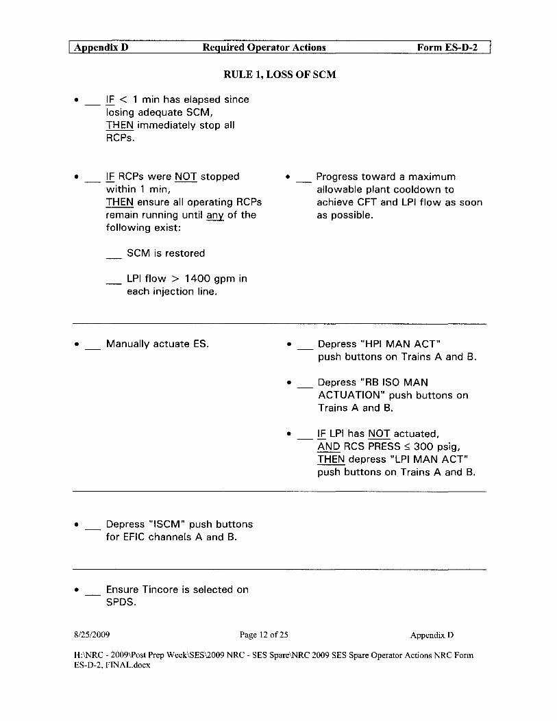
I AppendixD Required Operator Actions Form ES-D-2
RULE 1, LOSS OF SCM
• _ IE < 1 min has elapsed since losing adequate SCM, THEN immediately stop all RCPs.
• _ IE RCPs were NOT stopped within 1 min,
•
THEN ensure all operating RCPs remain running until any of the following exist:
SCM is restored
_ LPI flow > 1400 gpm in each injection line.
Manually actuate ES.
• Depress "ISCM" push buttons for EFIC channels A and B.
• Ensure Tincore is selected on SPDS.
• _ Progress toward a maximum allowable plant cooldown to achieve CFT and LPI flow as soon as possible.
• Depress "HPI MAN ACT" push buttons on Trains A and B.
• _ Depress "RB ISO MAN ACTUATION" push buttons on Trains A and B.
• _ IF LPI has NOT actuated, AND RCS PRESS ~ 300 psig, THEN depress "LPI MAN ACT" push buttons on Trains A and B.
8/2512009 Page 12 of25 AppendixD
H:\NRC - 2009\Post Prep Week\SES\2009 NRC - SES Spare\NRC 2009 SES Spare Operator Actions NRC Form ES-D-2, FINAL.docx

I Appendix D Required Operator Actions Form ES-D-2
RULE 2, HPI CONTROL
• _ i.E HPI has actuated, THEN bypass or reset ES actuation.
• Open MUP recirc prior to throttling HPI flow < 200 gpm/pump.
• _ i.E adequate SCM exists based, on Tincore, THEN throttle HPI to maintain required conditions.
• _ i.E adequate SCM can be maintained with 1 HPI pump, AND stopping second HPI pump is desired, THEN stop 1 HPI pump.
1 Obtain SRO concurrence to bypass or reset ES.
2 Bypass or reset ES actuation:
Auto
Manual
• _ i.E recirc to M UT is desired, THEN open MUP recirc to MUT valves:
1_ MUV-53 1_ MUV-257 ~
• _ i.E recirc to RB sump is desired, THEN open HPI recirc to sump valves:
MUV-543 MUV-544 - --MUV-545 MUV-546 - -
• _ Prevent exceeding NOT limit
• _ i.E OTSG isolated for TRACC, THEN maintain RCS PRESS --< 1000 psig.
• _ i.E PTS, SGTR, or dry OTSG exists, THEN maintain minimum adequate SCM.
• _ Ensure running HPI pump is aligned to MUT.
8/2512009 Page 13 of25 Appendix D
H:\NRC - 2009\Post Prep Week\SES\2009 NRC - SES Spare\NRC 2009 SES Spare Operator Actions NRC Form ES-D-2, FlNAL.docx

I AppendixD Required Operator Actions Form ES-D-2
RULE 3, EFW/AFW CONTROL
• Ensure available OTSGs are at or trending toward required level.
• IF manual control of EFW flow is desired, THEN establish manual EFIC control.
• _ IF adequate SCM does NOT exist, AND level in available OTSGs is NOT at or trending toward "ISCM" level, THEN establish manual required flow.
• _ IF adequate SCM exists, THEN throttle flow to prevent OTSG PRESS from lowering > 100 psig below desired PRESS.
"LLL" > 20in
"NAT CIRC" > 70%
"ISCM" > 90%
1
2
Obtain SRO concurrence to place EFIC in manual.
Control EFW to maintain required EFW flow and OTSG level.
3 _ IF EFW flow is NOT controlled, THEN depress EFIC channels
EFW
AFW
A and B "MANUAL PERMISSIVE" push buttons and close affected EFW block valve.
2 OTSGs > 280 gpm in 1 line to each OTSG
10TSG > 470 gpm in 1 line to 1 OTSG
20TSGs > 250 gpm to < 300 gpm/OTSG
10TSG > 450 gpm to < 600 gpm
• Do not allow OTSG level to lower.
8/2512009 Page 14 of25 AppendixD
H:\NRC - 2009\Post Prep Week\SES\2009 NRC - SES Spare\NRC 2009 SES Spare Operator Actions NRC Form ES-D-2, FINAL.docx

I AppendixD Required Operator Actions Form ES-D-2
• _ IF any of the following exist:
Tincore < 400°F, AND cooldown rate exceeds ITS limit
RCPs off, AND HPI flow exists
THEN perform required PTS actions.
RULE 4, PTS
•
•
•
8/25/2009 Page 15 of25
Throttle HPI flow to minimize adequate SCM.
Throttle LPI flow to minimize adequate SCM.
PTS is applicable until an Engineering evaluation has been completed.
Appendix D
H:\NRC - 2009\Post Prep Week\SES\2009 NRC - SES Spare\NRC 2009 SES Spare Operator Actions NRC Fonn ES-D-2, FINAL.docx

I Appendix D Required Operator Actions Form ES-D-2
RULE 7, PZR LEVEL CONTROL
1 IF PZR level is < PZR level band, THEN restore PZR level.
2 IE PZR level does NOT recover, THEN establish manual HPI flow.
3 IE PZR level recovers, THEN restore normal PZR conditions.
[Rule 2, HPI Control]
PZR Level Band
Rx at power> 20% 200 in to 240 in
Rx at power :S 20% 120 in to 200 in
Rx tripped 50 in to 1 20 in
• Cycle appropriate BWST to MUP valve to maintain MUT level ~ 55 in:
1_ MUV-73 1_ MUV-58
• Close MUV-49
1 _ Open MUV-24
2 _ Notify SSO to evaluate Emergency Plan entry.
3 _ IF PZR level does NOT recover, THEN start second MUP and --required cooling pumps.
[Rule 5, Diesel Load Control]
4 _ IF PZR level does NOT recover, THEN open additional HPI valves.
5 _ IE PZR level does NOT recover, THEN close MUP to MUT recircs: --
I_ MUV-53 1_ MUV-257 ~
• _ IF adequate SCM exists, AND letdown is desired, THEN CONCURRENTL Y PERFORM EOP-14, Enclosure 4, Letdown Recovery (if accessible).
8/25/2009 Page 16 of25 Appendix D
H:\NRC - 2009\Post Prep Week\SES\2009 NRC - SES Spare\NRC 2009 SES Spare Operator Actions NRC Fonn ES-D-2, FINAL.docx

I Appendix D Required Operator Actions Form ES-D-2
Section 4.15 Recovery From Letdown Isolation (Reference) [NOeS 000209]
IF recovery is due to high temperature THEN PROCEED to next step, .............................................................................................. 0
IF NOT THEN GO TO Step 0 .............................................................................................................. 0
IF MUDM-1A is in service, THEN PERFORM the following:
ENSURE CLOSED the following:
• MUV-133 MUDM-1B Inlet ...................................................................................... 0 • MUV-201 1A to 1 B Series ....................................................................................... 0 • MUV-116 MUDM-1A Outlet.. ................................................................................... 0
ENSURE OPEN the following:
• MUV-124 MUDM-1A Inlet ....................................................................................... 0 • MUV-200 1 B to 1A Series ....................................................................................... 0 • MUV-117 MUDM-1B Outlet.. ................................................................................... 0
IF MUDM-1 B is in service, THEN PERFORM the following:
ENSURE CLOSED the following:
• MUV-124 MUDM-1A Inlet ....................................................................................... 0 • MUV-200 1Bto 1ASeries ....................................................................................... 0 • MUV-117 MUDM-1B Outlet.. ................................................................................... 0
ENSURE OPEN the following:
• MUV-133 MUDM-1B Inlet ....................................................................................... 0 • MUV-201 1A to 1 B Series ....................................................................................... 0 • MUV-116 MUDM-1A Outlet.. ................................................................................... 0
ENSURE Block Orifice Isolation and Orifice Bypass are CLOSED:
ENSURE CLOSED the following:
• MUV-SO Block Orifice Isolation ............................................................................... 0 • MUV-S1 Block Orifice Bypass ................................................................................. 0
8/25/2009 Page 17 of25 AppendixD
H:\NRC - 2009\Post Prep Week\SES\2009 NRC - SES Spare\NRC 2009 SES Spare Operator Actions NRC Fonn ES-D-2, FlNAL.docx

I Appendix D Required Operator Actions Form ES-D-2
ENSURE two Letdown Coolers are being supplied by SW, AND Valve Alignment is arranged to cool letdown:
• MUHE-1A or MUHE-1C:
• ENSURE OPEN SWV-47 ........................................................................................ 0 • ENSURE OPEN SWV-50 ........................................................................................ 0
• MUHE-1B:
• ENSURE OPEN SWV-48 ........................................................................................ 0 • ENSURE OPEN SWV-49 ........................................................................................ 0
ENSURE a letdown flow path exists:
ENSURE at least 1 prefilter in service .................................................................................... 0 OR MUV-194 is OPEN ........................................................................................................ 0
ENSURE at least 1 MU demin in service ................................................................................ 0 OR MUV-126 is OPEN ........................................................................................................ 0 OR Bypassed per Step 0 ..................................................................................................... 0 OR Bypassed per Step 0 ..................................................................................................... 0
ENSURE at least 1 Post-Filter in service ................................................................................ 0 OR MUV-100 is OPEN ........................................................................................................ 0
ENSURE letdown isolation valves are OPEN:
IF recovering from high temp, THEN SELECT "MUV-49 HIGH TEMP BYPASS" switch to "BYPASS" ..................................................................................................................... 0
OPEN MUV-49 ....................................................................................................................... 0 ENSURE OPEN MUV-567 ..................................................................................................... 0
NOTE
Letdown (LD) Cooler 1C is NOT normally aligned for service whenever Coolers 1A and 1 B are both available. Normally LD Cooler "1 C" will have its SW outlet closed (SWV-691, RB entry required for opening) and its primary inlet (MUV-498) closed with electrical power removed.
IF it is desired to place "A" Letdown Cooler (MUHE-1A) in service, THEN PERFORM the following:
ENSURE OPEN the following:
• SWV-47, SW Inlet ................................................................................................... 0 • SWV-50, SW Outlet ................................................................................................ 0
OPEN MUV-38, Cooler Inlet ................................................................................................... 0 8125/2009 Page 18 of 25 Appendix D
H:\NRC - 2009\Post Prep Week\SES\2009 NRC - SES Spare\NRC 2009 SES Spare Operator Actions NRC Form ES-D-2, FINAL.docx
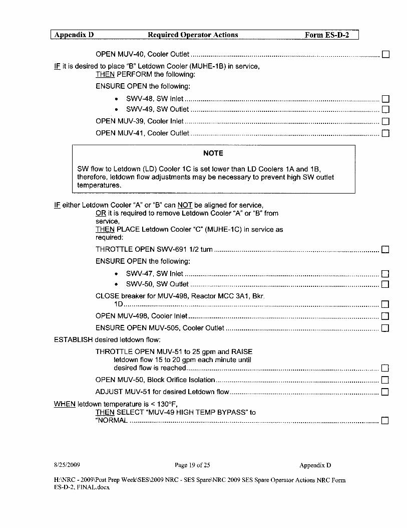
I Appendix D Required Operator Actions Form ES-D-2
OPEN MUV-40, Cooler Outlet ................................................................................................ 0 IF it is desired to place "B" Letdown Cooler (MUHE-1 B) in service,
THEN PERFORM the following:
ENSURE OPEN the following:
• SWV-48, SW Inlet ................................................................................................... 0 • SWV-49, SW Outlet ................................................................................................ 0
OPEN MUV-39, Cooler Inlet ................................................................................................... 0 OPEN MUV-41, Cooler Outlet ................................................................................................ 0
NOTE
SW flow to Letdown (LO) Cooler 1C is set lower than LO Coolers 1A and 1 B, therefore, letdown flow adjustments may be necessary to prevent high SW outlet temperatures. .
IF either Letdown Cooler "A" or "B" can NOT be aligned for service, OR it is required to remove Letdown Cooler "A" or "B" from service, THEN PLACE Letdown Cooler "C" (MUHE-1C) in service as required:
THROTTLE OPEN SWV-691 1/2 turn .................................................................................... 0 ENSURE OPEN the following:
• SWV-47, SW Inlet ................................................................................................... 0 • SWV-50, SW Outlet ................................................................................................ 0
CLOSE breaker for MUV-498, Reactor MCC 3A 1, Bkr. 10 .................................................................................................................................. 0
OPEN MUV-498, Cooler Inlet ................................................................................................. 0 ENSURE OPEN MUV-505, Cooler Outlet .............................................................................. 0
ESTABLISH desired letdown flow:
THROTTLE OPEN MUV-51 to 25 gpm and RAISE letdown flow 15 to 20 gpm each minute until desired flow is reached .................................................................................................. 0
OPEN MUV-50, Block Orifice Isolation ................................................................................... 0 ADJUST MUV-51 for desired Letdown flow ............................................................................ 0
WHEN letdown temperature is < 130°F, THEN SELECT "MUV-49 HIGH TEMP BYPASS" to "NORMAL ............................................................................................................................... 0
8/25/2009 Page 19 of25 Appendix D
H:\NRC - 2009\Post Prep Week\SES\2009 NRC - SES Spare\NRC 2009 SES Spare Operator Actions NRC Form ES-D-2, FINAL.docx

I Appendix D Required Operator Actions Form ES-D-2
IE MUDM-1A is to be returned to service, THEN PERFORM the following:
ENSURE OPEN the following:
• MUV-124 MUDM-1A Inlet ....................................................................................... D • MUV-116 MUDM-1A Outlet.. ................................................................................... D
ENSURE CLOSED the following:
• MUV-133 MUDM-1B Inlet ....................................................................................... D • MUV-117 MUDM-1B Outlet.. ................................................................................... D • MUV-200 1 B to 1A Series ....................................................................................... D • MUV-201 1A to 1 B Series ....................................................................................... D • MUV-126 MU Demin Bypass Valve ........................................................................ D
IF MUDM-1 B is to be returned to service, THEN PERFORM the following:
ENSURE OPEN the following:
• MUV-133 MUDM-1B Inlet ....................................................................................... D • MUV-117 MUDM-1B Outlet.. ................................................................................... D
ENSURE CLOSED the following:
• MUV-124 MUDM-1A Inlet ....................................................................................... D • MUV-116 MUDM-1A Outlet.. ................................................................................... D • MUV-200 1 B to 1A Series ....................................................................................... D • MUV-201 1A to 1 B Series ....................................................................................... D • MUV-126 MU Demin Bypass Valve ........................................................................ D
END OF SECTION
8/2512009 Page 20 of25 Appendix D
H:\NRC - 2009\Post Prep Week\SES\2009 NRC - SES Spare\NRC 2009 SES Spare Operator Actions NRC Form ES-D-2, FINAL.docx

I Appendix D Required Operator Actions Form ES-D-2
ENCLOSURE 1 CONTROL COMPLEX EMERGENCY VENTILATION AND COOLING
ACTIONS
1.1 Verify ES MCC 3AB is energized.
IF ES MCC 3AB is NOT energized, THEN energize ESMCC3AB.
NOTE
DETAILS
1 _ IF energized ES 480V Bus is powered from Diesel, THEN ensure Diesel load is S;2975 KW.
2 _ Depress transfer push button for ES MCC 3AB to energized bus.
A Train is preferred ifES has actuated with B ES 4160V Bus powered by B ES Diesel.
1.2 IF CC ventilation will be ES Diesel -powered by a Diesel, Max Allowable Load 3280KW THEN verify Diesel load is (BSP running) < Max Allowable Load.
ES Diesel Max Allowable Load 2960KW
(BSP shutdown)
Alternate AC Diesel 3280 KW
Max Allowable Load
A ES Diesel Load KW --
B ES Diesel Load KW --
Alternate AC Diesel Load KW --
8/25/2009 Page 21 of25 Appendix D
H:\NRC - 2009\Post Prep Week\SES\2009 NRC - SES Spare\NRC 2009 SES Spare Operator Actions NRC Form ES-D-2, FINAL.docx
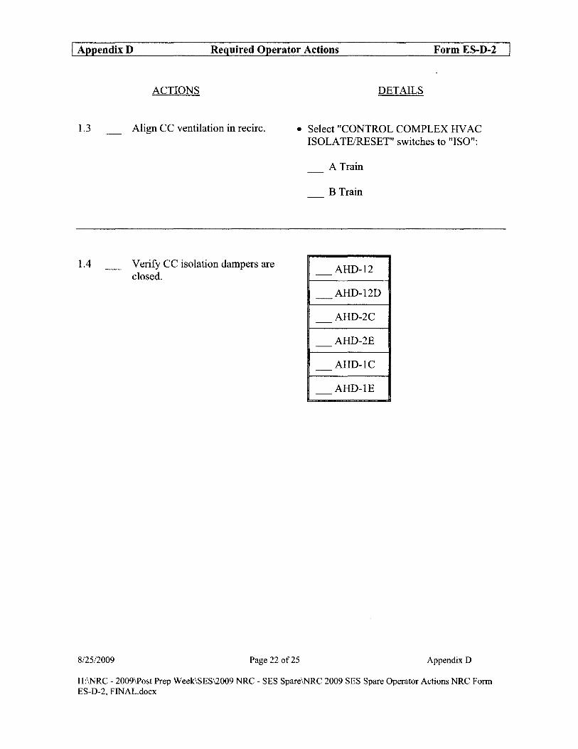
I Appendix D Required Operator Actions Form ES-D-2
ACTIONS
1.3 _ Align CC ventilation in recirc.
1.4 Verify CC isolation dampers are closed.
DETAILS
• Select "CONTROL COMPLEX HV AC ISOLATE/RESET" switches to "ISO":
A Train
B Train
AHD-12 -
AHD-12D -
AHD-2C -
AHD-2E -
AHD-IC -
AHD-IE -
8/25/2009 Page 22 of25 AppendixD
H:\NRC - 2009\Post Prep Week\SES\2009 NRC - SES Spare\NRC 2009 SES Spare Operator Actions NRC Form ES-D-2, FINAL.docx

I Appendix D Required Operator Actions Form ES-D-2
1.5
ACTIONS
Ensure CC ventilation fans are shut down.
NOTE
DETAILS
1 Stop Control Complex Return Fans:
A Train B Train
AHF-19A AHF-19B - -
2 Stop Control Complex Normal Duty Supply Fans:
A Train B Train
AHF-17A AHF-17B - -
A Train is preferred ifES has actuated with B ES 4160V Bus powered by B ES Diesel.
1.6
8125/2009
Start 1 train of CC ventilation in emergency reCIfC.
1 Start Control Complex Emergency Duty S I F upply ans:
A Train B Train
AHF-18A AHF-18B - -
2 Start Control Complex Return Fans:
A Train B Train
AHF-19A AHF-19B - -
Page 23 of25 Appendix D
H:\NRC - 2009\Post Prep Week\SES\2009 NRC - SES Spare\NRC 2009 SES Spare Operator Actions NRC Fonn ES-D-2, FINAL.docx
I Appendix D Required Operator Actions Form ES-D-2
1.5
ACTIONS
Ensure CC ventilation fans are shut down.
NOTE
DETAILS
1 Stop Control Complex Return Fans:
A Train B Train
AHF-19A AHF-19B - -
2 Stop Control Complex Normal Duty Supply Fans:
A Train B Train
AHF-17A AHF-17B - -
A Train is preferred ifES has actuated with B ES 4160V Bus powered by B ES Diesel.
1.6
8125/2009
Start 1 train of CC ventilation in emergency reCIfC.
1 Start Control Complex Emergency Duty S I F Upply ans:
A Train B Train
AHF-18A AHF-18B - -
2 Start Control Complex Return Fans:
A Train B Train
AHF-19A AHF-19B - -
Page 23 of25 Appendix D
H:\NRC - 2009\Post Prep Week\SES\2009 NRC - SES Spare\NRC 2009 SES Spare Operator Actions NRC Fonn ES-D-2, FINAL.docx

I Appendix D Required Operator Actions Form ES-D-2
1.7
1.8
8125/2009
ACTIONS
Ensure 1 EFIC fan is running.
Establish ventilation for chemistry sampling.
DETAILS
• _ IF starting AHF-54A, THEN perform the following:
Select "TEMP CONT. VV, CHV -113" switch to "MOD" position.
Start AHF-54A
• IF starting AHF-54B, THEN perform the following:
Select "TEMP CONT. VV, CHV -100" switch to "MOD" position.
Start AHF-54B
• Start 1 train of ventilation:
A Train B Train
AHF-20A AHF-20B - -in "SLOW" in "SLOW"
AHF-44A AHF-44B - -
_ AHF-30 (if available)
Page 24 of25 Appendix D
H:\NRC - 2009\Post Prep Week\SES\2009 NRC - SES Spare\NRC 2009 SES Spare Operator Actions NRC Form ES-D-2, FINAL.docx

I Appendix D Required Operator Actions
ACTIONS
1.9 _ IF all the following exist:
812512009
CC chiller running
Ventilation trains have NOT been shifted
THEN EXIT this enclosure.
Page 25 of25
Form ES-D-2
DETAILS
Appendix D
H:\NRC - 2009\Post Prep Week\SES\2009 NRC - SES Spare\NRC 2009 SES Spare Operator Actions NRC Fonn ES-D-2, FINAL.docx


![[Hier klicken und Titel eingeben] - guentner.asia · V1.01 . T.Wallrabenstein : 3.3.17 The 9.6.2010 . ... Only the RTU transmission mode will be supported (see MODBUS over Serial](https://static.fdocuments.in/doc/165x107/5b4f2efb7f8b9a206e8bceb8/hier-klicken-und-titel-eingeben-v101-twallrabenstein-3317-the-962010.jpg)


