Cryogenic Pressure Safety
69
Cryogenic Pressure Safety with Emphasis on Overpressure Protection of Low Temperature Helium Vessels Part 1 Pressure Safety Fundamentals Tom Peterson (SLAC) CSA Webinar February 2018
Transcript of Cryogenic Pressure Safety

Cryogenic Pressure Safety with Emphasis on Overpressure Protection of
Low Temperature Helium Vessels
Part 1
Pressure Safety Fundamentals
Tom Peterson (SLAC)
CSA Webinar
February 2018

Many Thanks to Our Sponsors
for Making This Class Possible
& Free to the Students
• Acme Cryogenics Inc.
• Circor Cryogenics-CPC Cryolab
• HPD (High Precision Devices)
• Cryoworks Inc.
• Tempshield Cryo-Protection
• WEKA AG
CSA, Feb 2018Cryogenic Pressure Safety, Part 1, Tom Peterson
2

Introduction
• The purpose of this lecture is to provide a review of
cryogenic pressure safety and pressurized gas hazards
• A lecture in two parts
– Pressure safety fundamentals
– Impact of pressure safety on design
• Pressure safety in cryogenics involves all the usual
pressurized gas concerns, plus:
– The possibility of pressurizing a closed volume via warm-up
– Possible embrittlement and resulting fracture of materials
• We start with some examples of incidents and “lessons
learned”
CSA, Feb 2018Cryogenic Pressure Safety, Part 1, Tom Peterson 33

Topics in cryogenic pressure safety • Part 1, this week – fundamentals
– Compliance with consensus standards, exceptional vessel methodology
– Sources of pressure
– Thermodynamics of cryogen expansion and venting
– Analytical methods for vent line and relief sizing
– Relief devices
– Conclusions and references
• Part 2, next week, impact on design – Example of a venting system analysis
– Examples of the impact on cryostat design
– Conclusions and references
CSA, Feb 2018Cryogenic Pressure Safety, Part 1, Tom Peterson
4

Two MRI system event videos
• http://www.youtube.com/watch?v=1R7Ksfo
sV-o
• http://www.youtube.com/watch?v=sceO38i
djic&feature=related
CSA, Feb 2018Cryogenic Pressure Safety, Part 1, Tom Peterson
5

Risks of excessive pressure
• Vessel rupture, explosion
• Freezing, burns, due to plume of cold gas or
liquid
• Discharge of fittings, pipe caps, valves
CSA, Feb 2018Cryogenic Pressure Safety, Part 1, Tom Peterson
6

Over Pressurization or explosion
due to rapid expansion• Without adequate venting or pressure-relief
devices on the containers, enormous pressures can
build up which can cause an explosion.
• Unusual or accidental conditions such as an
external fire, or a break in the vacuum which
provides thermal insulation, may cause a very
rapid pressure rise.
• The pressure relief valve must be properly
installed and free from obstruction.
CSA, Feb 2018Cryogenic Pressure Safety, Part 1, Tom Peterson 7
5/24/2021 7

Lessons Learned
• The following are a few “lessons learned” which
have been compiled from various sources. One
source of examples is the American Industrial
Hygiene Association, which has a section of their
website describing accidents and “lessons learned”
including several cryogenic accidents:
https://www.aiha.org/get-
involved/VolunteerGroups/LabHSCommittee/Pag
es/Lessons-Learned.aspx
CSA, Feb 2018Cryogenic Pressure Safety, Part 1, Tom Peterson 8
Lessons Learned • Empty 55 gallon drum (1999)
– At the Nevada Test Site, a waste handler was opening new, empty
55 gallon open-top drums. Upon removing the bolt from the drum
lid clamp, the ring blew off and the lid was ejected approximately
5 to 10 feet in the air, just missing the Waste Handler's face. The
drum did not hiss or show signs of pressurization.
– Because the Waste Handler had been properly trained to stand
away from the drum while opening it, he was not injured.
– The event was caused by the drums being manufactured and sealed
at sea level in Los Angeles and subsequently shipped to a much
higher elevation of approximately 6,000 feet at the Nevada Test
Site. The increased elevation, combined with the midday heat,
created sufficient pressure buildup to cause the lid to blow off
when the ring was being released.
– Lesson -- large force with small pressure times large areaCSA, Feb 2018
Cryogenic Pressure Safety, Part 1, Tom Peterson 9

CSA, Feb 2018Cryogenic Pressure Safety, Part 1, Tom Peterson 10
Lessons learned (continued) • 50 liter LN2 laboratory dewar explosion
– Transfer of LN2 from 160 liter dewar to 50 liter “laboratory”dewar
– Flex hose end from 160 l dewar would not fit in lab dewar neck
(normally a “wand” is inserted for filling), so a connection was made
with rubber hose over the OUTSIDE of the lab dewar neck and transfer
hose end
– “Slot”cut in rubber hose for vent
– Failure not initially caused by overpressure, but by cooling of upper part
of neck during fill! Seal between neck and vacuum jacket broke due to
differential thermal contraction.
– Seal to vacuum jacket broke after lab dewar nearly full, subsequent
overpressure with lack of sufficient vent caused explosion of lab dewar
– One person badly injured
– Lesson -- rupture of insulating vacuum with restricted venting resulted in
explosion

50 liter LN2 dewar explosion
CSA, Feb 2018 Cryogenic Pressure Safety, Part 1, Tom Peterson 11
Figures from “Safety in the Handling of Cryogenic Fluids,” by F. J. Edeskutyand W. F. Stewart, Plenum Press, NY, 1996.

Another LN2 dewar explosion, for the report, see
http://www.tdi.texas.gov/fire/documents/fmred022206.pdf
CSA, Feb 2018Cryogenic Pressure Safety, Part 1, Tom Peterson 12

CSA, Feb 2018Cryogenic Pressure Safety, Part 1, Tom Peterson
13

Pressure vessel and piping codes
and national laboratory standards• ASME Boiler and Pressure Vessel Code and ASME B31
Piping Codes – In general, we try to purchase vessels built to the code from code-
authorized shops
– Where code-stamping is not possible, we design (or specify designs) to the intent of the code and note implications of exceptions to the code
• 10 CFR 851 requirements for pressure systems for DOE contractors
• SLAC’s ES&H Manual Chapter 14, “Pressure Safety”
• Fermilab’s ES&H Manual (FESHM) pressure vessel standards – FESHM 5031 (general pressure vessel standard)
– FESHM 5031.6 (dressed cavity standard)
CSA, Feb 2018Cryogenic Pressure Safety, Part 1, Tom Peterson
14

10 CFR part 851
CSA, Feb 2018 Cryogenic Pressure Safety, Part 1, Tom Peterson 15

10 CFR part 851
Appendix A (4) (c)
CSA, Feb 2018 Cryogenic Pressure Safety, Part 1, Tom Peterson 16
If codes to not apply, we must provide a
level of safety greater than or equal to the applicable code.
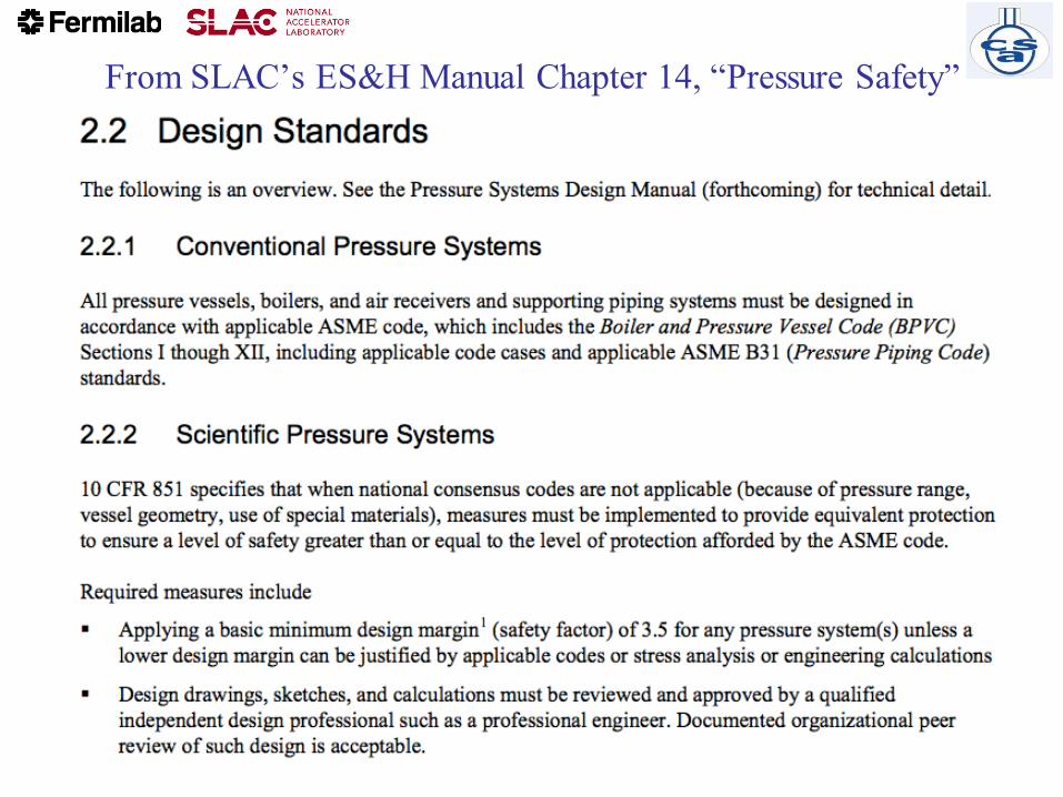
From SLAC’s ES&H Manual Chapter 14, “Pressure Safety”
CSA, Feb 2018 Cryogenic Pressure Safety, Part 1, Tom Peterson 17

CSA, Feb 2018Cryogenic Pressure Safety, Part 1, Tom Peterson
18
Issues for code compliance
for SRF dressed cavities• Cavity design that satisfies level of safety equivalent to that of a
consensus pressure vessel code is affected by
– use of the non-code material (niobium),
– complex forming and joining processes,
– a shape that is determined entirely by cavity RF performance,
– a thickness driven by the cost and availability of niobium sheet,
– and a possibly complex series of chemical and thermal treatments.
• Difficulties emerge pressure vessel code compliance in various areas
– Material not approved by the pressure vessel code
– Loadings other than pressure
• Thermal contraction
• Tuning
– Geometries not covered by rules
– Weld configurations difficult to inspect

CSA, Feb 2018Cryogenic Pressure Safety, Part 1, Tom Peterson
19
Safety/compliance issue summary
• In the U.S., Europe, and Japan, SRF helium containers and
part or all of the RF cavity fall under the scope of the local
and national pressure vessel rules.
• Thus, while used for its superconducting properties,
niobium ends up also being treated as a material for
pressure vessels.
• For various reasons, it is not possible to completely follow
all the rules of the pressure vessel codes for most of these
SRF helium vessel designs
• Thus, we have to invoke the “equivalent level of safety”
allowed by 10 CFR 851.

CSA, Feb 2018Cryogenic Pressure Safety, Part 1, Tom Peterson
20
General solution
• In applying ASME code procedures, key elements demonstrating the
required level of design safety are
– the establishment of a maximum allowable stress
– And for external pressure design, an accurate approximation to the true
stress strain curve
• Apply the ASME Boiler and Pressure Vessel Code as completely as
practical
– Exceptions to the code may remain
– We have to show the risk is minimal
• Satisfy the requirement for a level of safety greater than or equal to
that afforded by ASME code.
• Fermilab, Brookhaven, Jefferson Lab, Argonne Lab, and others in the
U.S. have taken a similar approach

CSA, Feb 2018Cryogenic Pressure Safety, Part 1, Tom Peterson
21
Fermilab developed a standard and guidelines
for vessels which cannot fully meet the
pressure vessel code (FESHM 5031.6)
• Design drawings, sketches, and calculations are reviewed and
approved by qualified independent design professionals.
• Only qualified personnel must be used to perform examinations and
inspections of materials, in-process fabrications, non-destructive tests,
and acceptance tests.
• Documentation, traceability, and accountability is maintained for each
pressure vessel and system, including descriptions of design, pressure
conditions, testing, inspection, operation, repair, and maintenance.
CSA, Feb 2018Cryogenic Pressure Safety, Part 1, Tom Peterson
22
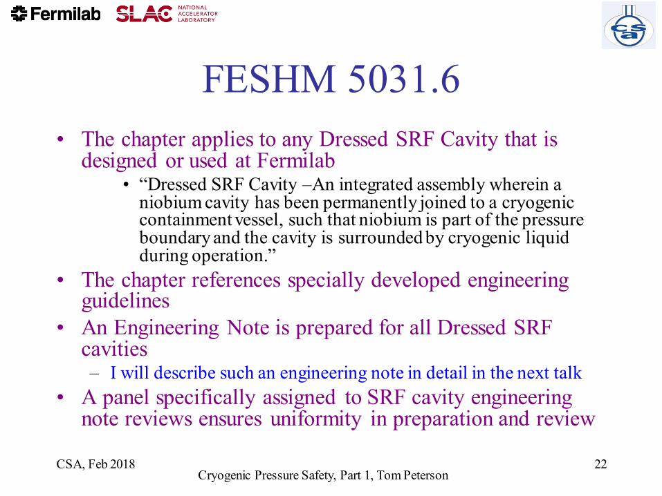
FESHM 5031.6
• The chapter applies to any Dressed SRF Cavity that is designed or used at Fermilab
• “Dressed SRF Cavity –An integrated assembly wherein a niobium cavity has been permanently joined to a cryogenic containment vessel, such that niobium is part of the pressure boundary and the cavity is surrounded by cryogenic liquid during operation.”
• The chapter references specially developed engineering guidelines
• An Engineering Note is prepared for all Dressed SRF cavities – I will describe such an engineering note in detail in the next talk
• A panel specifically assigned to SRF cavity engineering note reviews ensures uniformity in preparation and review

Pressure Vessel Code Scope
CSA, Feb 2018 Cryogenic Pressure Safety, Part 1, Tom Peterson 23
ASME Section VIII, Division 1, describes scope in terms of what is excluded. Key general exclusions are copied here from U-1(c)(2)(-h) and U-1(c)(2)(-i):
Hence the fundamental rule for the scope (with some specific exceptions, e.g., pumps, compressors, piping systems, water tanks): 15 psi or more, and 6 inches cross section or more.
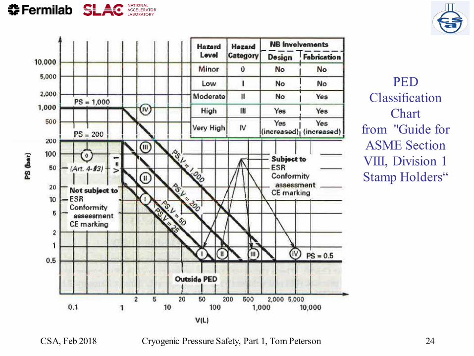
PED
Classification
Chart
from "Guide for
ASME Section
VIII, Division 1
Stamp Holders“
CSA, Feb 2018 Cryogenic Pressure Safety, Part 1, Tom Peterson 24

ASME Section VIII, Division 1
versus PED version 2014/68/EU • Note that the scopes of the ASME BPVC and PED version
2014/68/EU codes differ
• Differences between PED requirements and ASME requirements are described the document, "Guide for ASME Section VIII, Division 1 Stamp Holders“, which compares ASME Section VIII, Division 1 with PED version 2014/68/EU
• The comparisons indicate equivalent or higher level of requirements for the EU standards for Category III vessels.
• In general, material requirements, design requirements including formal design review and approval, allowable stresses, construction, inspection, and test requirements are similar or sometimes include more stringent requirements than ASME and also sometimes more responsibility placed on the manufacturer.
CSA, Feb 2018Cryogenic Pressure Safety, Part 1, Tom Peterson
25

Use of CE stamped vessel at SLAC
• We have an electron microscope pressure vessel of 283.6 liters volume with CE stamp
• The gas is sulfur hexafluoride at a pressure up to 5 bar
• Temperature range is ambient (5 C to 40 C).
• The pressure-volume product of 1418 bar-liters places this vessel in PED Hazard Category III
• A review concluded that this Category III CE-stamped vessel has a level of safety equivalent to what would have been provided by ASME pressure vessel codes for this vessel.
CSA, Feb 2018Cryogenic Pressure Safety, Part 1, Tom Peterson
26
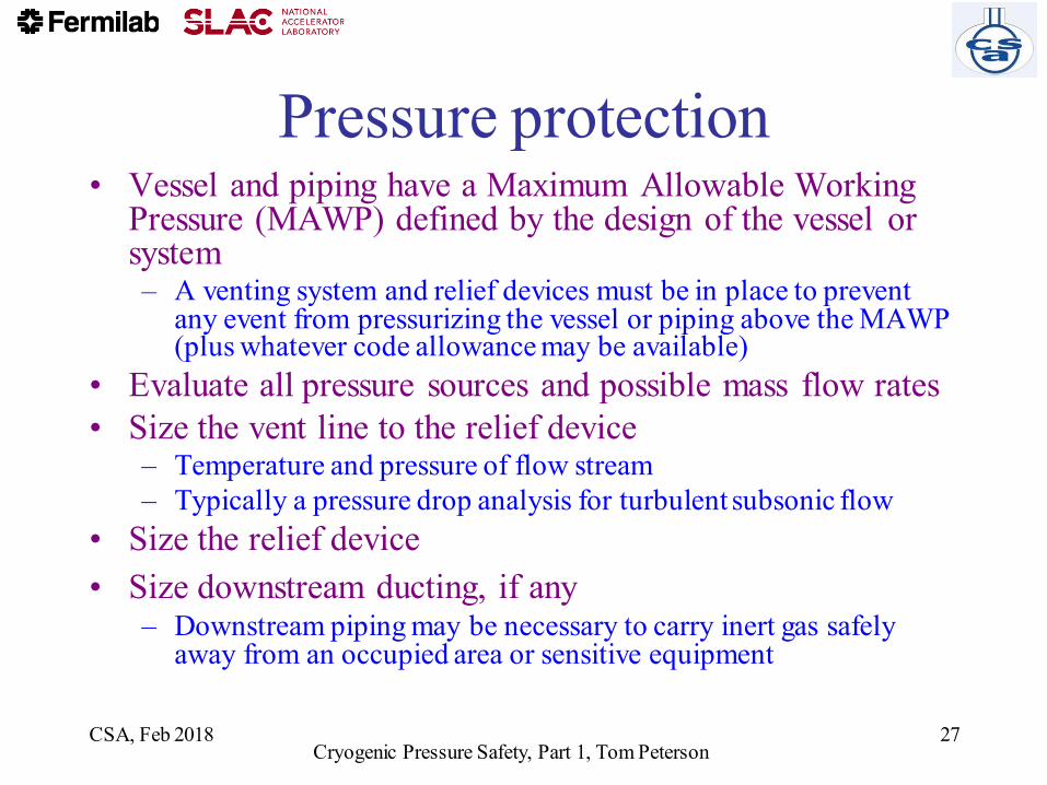
Pressure protection • Vessel and piping have a Maximum Allowable Working
Pressure (MAWP) defined by the design of the vessel or system– A venting system and relief devices must be in place to prevent
any event from pressurizing the vessel or piping above the MAWP (plus whatever code allowance may be available)
• Evaluate all pressure sources and possible mass flow rates
• Size the vent line to the relief device – Temperature and pressure of flow stream
– Typically a pressure drop analysis for turbulent subsonic flow
• Size the relief device
• Size downstream ducting, if any– Downstream piping may be necessary to carry inert gas safely
away from an occupied area or sensitive equipment
CSA, Feb 2018Cryogenic Pressure Safety, Part 1, Tom Peterson
27

ASME pressure vessel code --
relief devices
• Section VIII of the ASME Code provides
fundamental guidance regarding pressure relief
requirements.
– ASME Section VIII, Division 1, UG-125 through
UG133, for general selection, installation and valve
certification requirements
– ASME Section VIII, Appendix 11 for flow capacity
conversions to SCFM-air
• For Div. 2, relevant information is found in Part 9.
CSA, Feb 2018Cryogenic Pressure Safety, Part 1, Tom Peterson
28
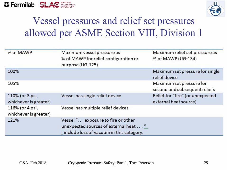
Vessel pressures and relief set pressures
allowed per ASME Section VIII, Division 1
CSA, Feb 2018 Cryogenic Pressure Safety, Part 1, Tom Peterson 29

Compressed Gas Association publication,
CGA S-1.3, “Pressure Relief Device Standards”
• Extensive guidance on requirements for
relief devices consistent with ASME code
– Applicable where MAWP and venting pressure
exceed 15 psig
• I will not provide a detailed discussion of
CGA S-1.3, but rather just point to a few
key issues and most useful elements of the
standard
CSA, Feb 2018Cryogenic Pressure Safety, Part 1, Tom Peterson
30

Note: we take exception to
paragraph 2.2 in CGA S-1.3• “CGA believes that reclosing PRDs on a container shall be able
to handle all the operational emergency conditions except fire, for which reclosing or nonreclosing PRDs shall be provided. The operational emergency conditions referred to shall include but not be limited to loss of vacuum, runaway fill, and uncontrolled operation of pressure buildup devices.”
• Exception: we treat loss of vacuum to air, with the very high heat flux resulting from condensation on the liquid helium temperature surface of a container, like the fire condition and may use nonreclosing relief devices for that situation
• This interpretation is consistent with wording in the ASME code, Section VIII, Division I, UG-125, which refers to “. . . exposure to fire or other unexpected sources of external heat.“
CSA, Feb 2018Cryogenic Pressure Safety, Part 1, Tom Peterson
31

Compressed Gas Association publication,
CGA S-1.3, “Pressure Relief Device Standards”
• From CGA S-1.3: Among the particular issues which must be addressed for low temperature vacuum jacketed helium containers are
– the temperature at which liquid-to-gas evolution should be estimated for the supercritical fluid at its venting pressure (CGA S-1.3 is very useful here; I’ll discuss this)
– the warming of the cold fluid passing through a long vent line (CGA S-1.3 also provides useful practical approximation methods here which I will discuss)
– the volume generated per unit heat added (we have data from lab tests about this which provide useful numbers)
CSA, Feb 2018Cryogenic Pressure Safety, Part 1, Tom Peterson
32
Sources of pressure -- mechanical
• Compressors, pumps
– Screw compressors are positive displacement devices
– Worst case flow may be with high suction pressure as limited by
inlet-side reliefs or pump/compressor motor power
• Calculate worst-case flow as highest inlet density combined with
known displacement volume
• Or consider power limitations of pump or compressor motor
• Connection to a higher pressure source, such as a tube
trailer
– Evaluate the mass flow as determined by the pressure drop from
the highest possible source pressure to the MAWP of vessel to be
protected
CSA, Feb 2018Cryogenic Pressure Safety, Part 1, Tom Peterson
33

Sources of pressure -- heat• Trapped volume, slow warm-up and pressurization with normal heat
inleak
– All possible volumes which may contain “trapped” (closed off by valves or by other means) cold fluid require small reliefs
– Rate of warm-up may be evaluated, generally slow enough that trapped volume reliefs are not individually analyzed.
• Loss of vacuum to helium with convection and conduction through helium gas
• Sudden large heat influx to a liquid-helium temperature container due to condensation of nitrogen or air on the surface
– Either through MLI or, worst-case, on a bare metal surface
• Stored energy of a magnetic field
– May provide a larger flow rate than loss of insulating vacuum
• Fire, with heat transport through the gas-filled insulation space
CSA, Feb 2018Cryogenic Pressure Safety, Part 1, Tom Peterson
34
Nominal heat loads
• Working numbers for making heat load
estimates
– ~1.5 W/m2 from 300 K to MLI-insulated
(typically about 30 layers) cold surface
– ~50 mW/m2 from 80 K to MLI-insulated
(typically about 10 layers) 4.5 K or 2 K surface
• Note that support structures and “end
effects” may dominate the total heat load
CSA, Feb 2018Cryogenic Pressure Safety, Part 1, Tom Peterson
35

Heat flux due to loss of insulating
vacuum as a source of pressure
• W. Lehman and G. Zahn, “Safety Aspects for LHe Cryostats and LHe
Transport Containers,” ICEC7, London, 1978
• G. Cavallari, et. al., “Pressure Protection against Vacuum Failures on
the Cryostats for LEP SC Cavities,” 4th Workshop on RF
Superconductivity, Tsukuba, Japan, 14-18 August, 1989
• M. Wiseman, et. al., “Loss of Cavity Vacuum Experiment at CEBAF,”Advances in Cryogenic Engineering, Vol. 39, 1994, pg. 997.
• T. Boeckmann, et. al., “Experimental Tests of Fault Conditions During
the Cryogenic Operation of a XFEL Prototype Cryomodule,”DESY.
CSA, Feb 2018Cryogenic Pressure Safety, Part 1, Tom Peterson
36

Heat flux conclusions
• T. Boeckmann, et. al. (DESY)– Air inflow into cavity beam vacuum greatly damped by RF cavity
structures
• Various authors also comment about layer of ice quickly reducing heat flux
• Heat flux curves for liquid helium film boiling with a delta-T of about 60 K agree with these heat flux numbers (next slides)
• I use 4 W/cm2 for bare metal surfaces
CSA, Feb 2018Cryogenic Pressure Safety, Part 1, Tom Peterson
37

Underlying thermodynamics
• Nitrogen freezes at 63 K
• Oxygen freezes at 55 K
• So heat flux for air condensation begins to become large with condensing surface temperatures under 63 K
• Delta-T to liquid helium will be around 58 K or less
• Film boiling of helium with 50 K to 60 K delta-T will provide about 4 W/cm2
CSA, Feb 2018Cryogenic Pressure Safety, Part 1, Tom Peterson
38
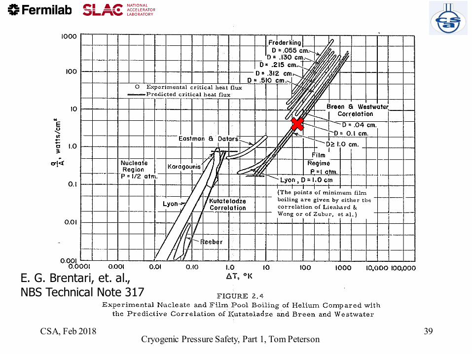
E. G. Brentari, et. al., NBS Technical Note 317
CSA, Feb 2018Cryogenic Pressure Safety, Part 1, Tom Peterson
39

Atmospheric air rushing into a vacuum space and condensing
on a surface deposits about 11 kW per cm2 of air hole inlet area.
In many cases, heat flux will be limited by this air hole inlet
size rather than low-temperature surface area.
CSA, Feb 2018 Cryogenic Pressure Safety, Part 1, Tom Peterson 40

Conversion of heat to mass flow
• Low pressures, below the critical pressure – Latent heat of vaporization
– Net flow out is vapor generated by the addition of heat minus the amount of vapor left behind in the volume of liquid lost
– For helium at pressures approaching the critical pressure (2.3 bar), the density and mass of vapor “left behind” in the volume formerly occupied by the boiled liquid can be significant, so this may be an important factor in reducing mass flow to a net mass flow out.
• High pressures, above the critical pressure – Heat added results in fluid expelled
– A “pseudo latent heat” can be evaluated
CSA, Feb 2018Cryogenic Pressure Safety, Part 1, Tom Peterson
41

Supercritical fluid -- energy
added per unit mass expelled The pressure of a liquid helium container during venting will
often exceed the critical pressure of helium (2.3 bar)
CSA, Feb 2018 Cryogenic Pressure Safety, Part 1, Tom Peterson 42

Pseudo latent heat heat – 4 atm helium
Temperature (K) Density (g/liter) v(dh/dv)p (J/g)
(heat aborbed per unit
of mass expelled)
5.0 124.2 29.8
5.5 109.4 24.6
6.0 82.6 19.8
6.5 55.0 21.4
7.0 42.7 24.8
CSA, Feb 2018Cryogenic Pressure Safety, Part 1, Tom Peterson
43
Venting occurs at a temperature near (not exactly, but close, more later) where v(dh/dv)p is at a minimum, so for our 4.1 bar venting with loss of vacuum, around 6 K.

Relief venting
• Up to now, we have discussed estimation of
the venting flow rate
• In summary
– We have a vessel or piping MAWP
– We have a mass flow rate provided either by
compressors/pumps or heating of low
temperature fluid which must be removed from
that vessel at or below the MAWP
CSA, Feb 2018Cryogenic Pressure Safety, Part 1, Tom Peterson
44

Berkeley MRI magnet quench
• https://www.youtube.com/watch?v=QRahB
usouRs
CSA, Feb 2018Cryogenic Pressure Safety, Part 1, Tom Peterson
45

Venting flow analyses
• Size piping to the relief device
• Size the relief device
– Typically using the vendor-provided or
standard relief device formulas and charts
• Size piping downstream of the relief device
• A somewhat different venting flow analysis
-- estimate flow from a rupture or open
valve into a room for an ODH analysis
CSA, Feb 2018Cryogenic Pressure Safety, Part 1, Tom Peterson
46

Constraints and assumptions
• For relief and vent pipe sizing
– Typically flow driven by a Maximum Allowable Working Pressure (MAWP, as defined by code requirements) at the vessel
– Pipe size and relief device size are the free parameters
• Perhaps also pipe routing
– Flow rate may be determined by a compressor or pump capacity or heat flux to a low temperature vessel
CSA, Feb 2018Cryogenic Pressure Safety, Part 1, Tom Peterson
47

Venting and relief sizing analysis
• Conservative, err on the safe side
– Venting is typically not steady-state, very dynamic
– Make simplifying assumptions on the safe side
• For example, flow rate estimate should be safely on the high side for relief sizing
• Reviewable
– Simplest and most straightforward analysis which demonstrates requirement
– Of course, more sophisticated analysis (such as FEM fluid dynamic simulation may be necessary for a system with sever constraints)
CSA, Feb 2018Cryogenic Pressure Safety, Part 1, Tom Peterson
48

Vent line flow temperature
The temperature into the relief device may be higher than the exit temperature due to heat transfer to the flow via the vent pipe. For very high flow rates and a relatively short vent line, this temperature rise may be insignificant. A simple energy balance on the flow and stored energy in the vent line, with an approximate and conservatively large convection coefficient may provide a safely conservative estimate of the temperature rise. For a long vent line, a more detailed analysis may be required in sizing the relief device. CGA S1.3, paragraph 6.1.4 and following, provides some guidance for this analysis.
This exit temperature will typically be 5 K - 6 K for a liquid helium container venting at a somewhat supercritical pressure.
CSA, Feb 2018 Cryogenic Pressure Safety, Part 1, Tom Peterson 49

Vent line pressure drop
evaluation
CSA, Feb 2018 Cryogenic Pressure Safety, Part 1, Tom Peterson 50
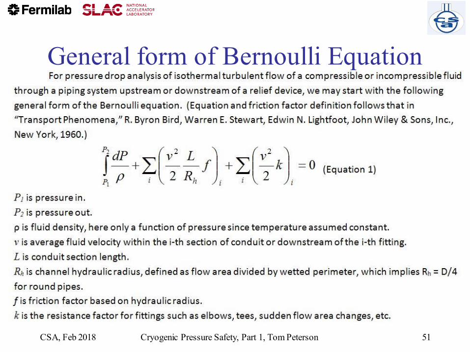
General form of Bernoulli Equation
CSA, Feb 2018 Cryogenic Pressure Safety, Part 1, Tom Peterson 51

Pressure drop analysis,
working formula for round pipes
This is a form of the D'Arcy-Weisbach formula. With pressure drop
expressed as head loss, this is sometimes called simply the Darcy formula. (Note that delta-P changed signs here, to a positive number.)
CSA, Feb 2018 Cryogenic Pressure Safety, Part 1, Tom Peterson 52

Crane Technical Paper #410
• Crane Technical Paper #410 “Flow of Fluids through Valves, Fittings, and Pipes”
• A classic reference, still available in updated forms
• Contains many forms of Bernoulli Equation and other formulas for both compressible and incompressible flow
• Relief valve and rupture disk catalogue formulas often reference Crane Technical Paper #410
• My only criticism (and strictly my personal opinion) -- I do not like the incorporation of unit conversions into formulas, which is too common in these engineering
handbooks
CSA, Feb 2018Cryogenic Pressure Safety, Part 1, Tom Peterson
53

Crane Technical Paper #410 “Flow of Fluids
through Valves, Fittings, and Pipes”
CSA, Feb 2018 Cryogenic Pressure Safety, Part 2, Tom Peterson 54
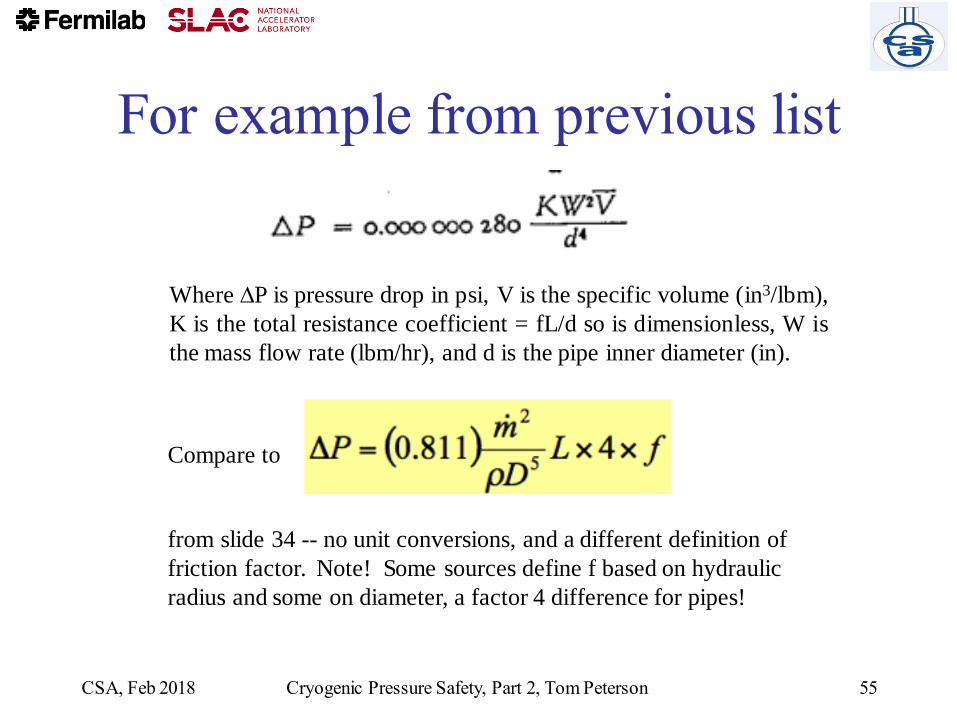
Where P is pressure drop in psi, V is the specific volume (in3/lbm),
K is the total resistance coefficient = fL/d so is dimensionless, W is
the mass flow rate (lbm/hr), and d is the pipe inner diameter (in).
For example from previous list
Compare to
from slide 34 -- no unit conversions, and a different definition of
friction factor. Note! Some sources define f based on hydraulic
radius and some on diameter, a factor 4 difference for pipes!
CSA, Feb 2018 Cryogenic Pressure Safety, Part 2, Tom Peterson 55

Rupture disk and
relief valve sizing• Flow will typically be choked (sonic) or nearly
choked in a relief valve or rupture disk
– Inlet pressure is at least 15 psig (1 atm gauge) for
ASME approved relief devices
– Discharge is to atmosphere
• This makes analysis relatively simple
– Relief valve catalogues and rupture disk catalogues
have good, practical working formulas and charts for
sizing relief devices
CSA, Feb 2018Cryogenic Pressure Safety, Part 1, Tom Peterson
56
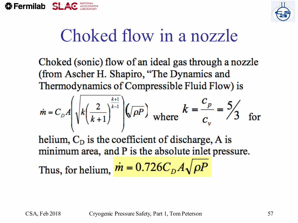
Choked flow in a nozzle
CSA, Feb 2018 Cryogenic Pressure Safety, Part 1, Tom Peterson 57
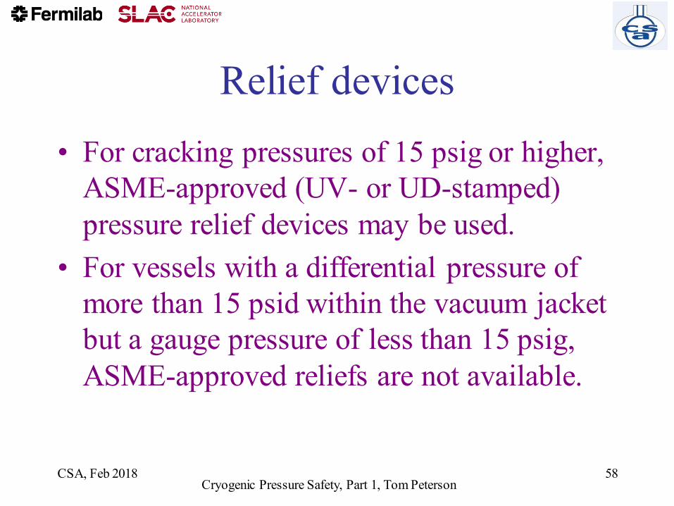
Relief devices
• For cracking pressures of 15 psig or higher,
ASME-approved (UV- or UD-stamped)
pressure relief devices may be used.
• For vessels with a differential pressure of
more than 15 psid within the vacuum jacket
but a gauge pressure of less than 15 psig,
ASME-approved reliefs are not available.
CSA, Feb 2018Cryogenic Pressure Safety, Part 1, Tom Peterson
58

From the
BS&B
rupture
disk
catalogue
CSA, Feb 2018 Cryogenic Pressure Safety, Part 1, Tom Peterson 59

Rupture disks
• Various types, some pre-etched or with knife edge, or failure in collapse (pressure on the dome) and other designs and materials
– Difficult to set a precise opening pressure
• A last resort device since they do not close – You don’t want these opening in normal operations
– Switching valves available for dual disks such that one can be replaced while the other holds pressure and provides protection
• Inexpensively provide very large capacity, so typical for the worst-case loss of vacuum – Operational reclosing relief valves set at a safely lower pressure
(80% of RD or less) prevent accidental opening of the rupture disk
CSA, Feb 2018Cryogenic Pressure Safety, Part 1, Tom Peterson
60

Relief valves
Image from Rockwood Swendeman brochure
• Even though valve at
room temperature,
will cool upon
relieving, so need
cold-tolerant material
and design
• Take care to provide
ASME UV-stamped
valves for code-
stamped vessels
CSA, Feb 2018Cryogenic Pressure Safety, Part 1, Tom Peterson
61

Relief valves
• Sizing best done via valve manufacturer
information
– Shape of valve body, type of plug make sizing
unique to the valve design
– Manufacturers certify flow capacity for UV-
stamped (ASME approved) valves
CSA, Feb 2018Cryogenic Pressure Safety, Part 1, Tom Peterson
62
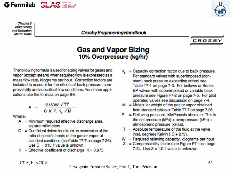
CSA, Feb 2018Cryogenic Pressure Safety, Part 1, Tom Peterson
63

Conclusions for piping and
emergency venting
• Cryogenic vessels and piping generally fall under the scope of the
ASME pressure vessel and piping codes
• Protection against overpressure often involves not only sizing a rupture
disk or relief valve but sizing vent piping between those and the vessel,
and also perhaps further ducting downstream of the reliefs
• Loss of vacuum to air with approximately 4 W/cm2 heat flux on bare
metal surfaces at liquid helium temperatures can drive not only the
design of the venting system but pipe sizes within the normally
operational portions of the cryostat
• Piping stability due to forces resulting from pressure around expansion
joints is sometimes overlooked and may also significantly influence
mechanical design
CSA, Feb 2018Cryogenic Pressure Safety, Part 1, Tom Peterson
64

References – Standards and Codes
• ASME Boiler and Pressure Vessel Code, Section VIII, Division 1 and Division 2, 2015, Rules for Construction of Pressure Vessels
• ASME B31.3-2014, Process Piping, ASME Code for Pressure Piping
• CGA S-1.3, “Pressure Relief Device Standards”, Compressed Gas Association, 2005.
• EUD 2014/68/EU DIRECTIVE — Directive 2014/68/EU of the European Parliament and of the Council of 15 May 2014 on the harmonisation of the laws of the Member States relating to the making available on the market of pressure equipment
• ASME Document PTB-10-2015, "Guide for ASME Section VIII, Division 1 Stamp Holders”
CSA, Feb 2018Cryogenic Pressure Safety, Part 1, Tom Peterson
65
References – National Lab Standards
CSA, Feb 2018 Cryogenic Pressure Safety, Part 1, Tom Peterson 66
• SLAC ES&H Manual, Chapter 14: Pressure Systems – http://www-group.slac.stanford.edu/esh/hazardous_activities/pressure/
• SLAC ES&H Manual, Chapter 36: Cryogenic and Oxygen Deficiency Hazard Safety
– http://www-group.slac.stanford.edu/esh/hazardous_substances/cryogenic/
• Fermilab ES&H Manual, Chapter 5031: Pressure Vessels– http://esh-docdb.fnal.gov/cgi-bin/ShowDocument?docid=456
• Fermilab ES&H Manual, Chapter 5031.6: Dressed Niobium SRF Cavity Pressure Safety
– And associated document: “Guidelines for the Design, Fabrication, Testing and Installation of SRF Nb Cavities,” Fermilab Technical Division Technical Note TD-09-005
– http://esh-docdb.fnal.gov/cgi-bin/ShowDocument?docid=1097
• Fermilab ES&H Manual, Chapter 5032: Cryogenic System Review – http://esh-docdb.fnal.gov/cgi-bin/ShowDocument?docid=528

References – Heat Flux Measurements
• W. Lehman and G. Zahn, “Safety Aspects for LHe Cryostats and LHe Transport Containers,” ICEC7, London, 1978
• G. Cavallari, et. al., “Pressure Protection against Vacuum Failures on the Cryostats for LEP SC Cavities,” 4th Workshop on RF Superconductivity, Tsukuba, Japan, 14-18 August, 1989
• M. Wiseman, et. al., “Loss of Cavity Vacuum Experiment at CEBAF,” Advances in Cryogenic Engineering, Vol. 39, 1994, pg. 997.
• T. Boeckmann, et. al., “Experimental Tests of Fault Conditions During the Cryogenic Operation of a XFEL
Prototype Cryomodule,” DESY.
CSA, Feb 2018Cryogenic Pressure Safety, Part 1, Tom Peterson
67

References – Technical• “Flow of Fluids through Valves, Fittings, and Pipes,” Crane
Technical Paper #410.
• E. G. Brentari, et. al., “Boiling Heat Transfer for Oxygen, Nitrogen, Hydrogen, and Helium,” NBS Technical Note 317, 1965.
• NBS Technical Note 631, “Thermophysical Properties of Helium-4 from 2 to 1500 K with Pressures to 1000 Atmospheres”, 1972.
• Vincent D. Arp and Robert D. McCarty, “ThermophysicalProperties of Helium-4 from 0.8 to 1500 K with Pressures to 2000 Atmospheres,” National Institute of Standards and Technology (NIST) Technical Note 1334, 1989.
• HEPAK (by Cryodata, Inc.)
CSA, Feb 2018Cryogenic Pressure Safety, Part 1, Tom Peterson
68

References – General
• R. Byron Bird, Warren E. Stewart, Edwin N. Lightfoot, “Transport Phenomena,” John Wiley &Sons, 1960.
• S. W. VanSciver, “Helium Cryogenics,” Plenum Press, 1986.
• Frederick J. Edeskuty and Walter F. Stewart, “Safety in the Handling of Cryogenic Fluids,” Plenum Press, New York, 1996.
• R.H. Kropschot, et. al., “Technology of Liquid Helium,” NBS Monograph 111
• Ascher H. Shapiro, “The Dynamics and Thermodynamics of Compressible Fluid Flow,”Wiley, 1953.
CSA, Feb 2018Cryogenic Pressure Safety, Part 1, Tom Peterson
69