Cryogenic Globe Control Valvevsicontrols.com/wp-content/uploads/schedePDF/GLC_Catalogue.pdf ·...
12
GLC Cryogenic Globe Control Valve
Transcript of Cryogenic Globe Control Valvevsicontrols.com/wp-content/uploads/schedePDF/GLC_Catalogue.pdf ·...
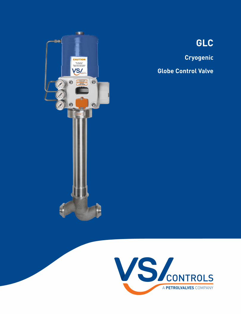
GLCCryogenic
Globe Control Valve
GLc GLOBE CONTROL VALVE2
The VSI Controls GLc Series comprises globe-type cryogenic control valves with single seat, rugged trim and cryogenic extension welded to the body, making them the ideal choice for cold boxes in industrial gas plants, where operating temperatures may reach -425°F (-253°C).
The design of the bonnet cryogenic extension allows easy access to the valve’s trim, making any maintenance activities easier and quicker; as the trim is assembled from the upper portion of the extension (top entry), removal and replacement of internal components are carried out without affecting the integrity of the cold box.
During operation a small fraction of the liquefied gas goes into the inner part of the extension where it is vaporized. This gas barrier created between the cryogenic liquid that flows through the body and the top of the extension isolates the valve packing, protecting it from the ultra-low temperatures and prevents the packing from freezing.
Pressure resulting from part of the liquid that is vaporized prevents that additional quantities of liquefied gas continue entering into the inner part of the extension. The design of the extension, plug and the sealing assures a small vaporization of the fluid during the cooling process of the valve.
The GLc Series is available in sizes from ½ to 10 inches and pressure classes from ANSI 150 to 600. Bodies of conventional globe-style or angle-style are designed with uniform wall thicknesses to reduce the total weight of the valve.
A spring-cylinder actuator offers excellent positioning accuracy and high actuating thrusts, which increases even more the notable sealing capacity of the GLc Series.
Adopting interchangeable components and sharing many design solutions already proven in the renowned GLs valves, make the GLc Series one of the most reliable and versatile cryogenic control valves in the market.
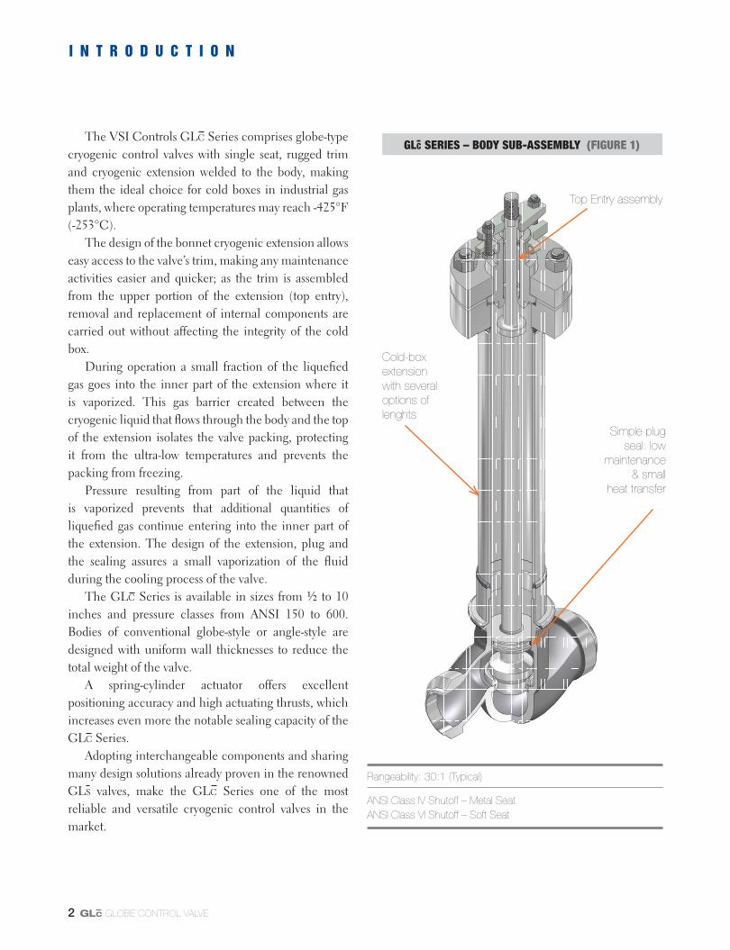
GLC SERIES – BODY SUB-ASSEMBLY (FIGURE 1)
Rangeability: 30:1 (Typical)
ANSI Class IV Shutoff – Metal SeatANSI Class VI Shutoff – Soft Seat
Top Entry assembly
Simple plugseal: low
maintenance& small
heat transfer
Cold-boxextensionwith severaloptions oflenghts
I N T R O D U C T I O N

GLc GLOBE CONTROL VALVE 3
Body
The optimized geometry of the GLc Series valve bod-ies presents smooth curves and a flow passageway nearly constant, which reduce the flowing fluid turbulence and increase the valve flow rate capacity.
In addition to the cryogenic extension welded to the body, the small number of internal components and they reduced weight enable the heat transfers during the valve operation to be kept within low levels, increasing the pro-cess thermal efficiency.
The construction of the body and the cryogenic exten-sion in a single piece, with no gaskets or flanged connec-tions eliminates the risk of leakage inside the cold box.
GLc valve bodies are usually manufactured in bronze or austenitic stainless steel, materials that have a face-centered cubic (FCC) structure presenting high yield and tensile, as well as high impact strengths at cryogenic temperatures.
GLc VALVE WITH GLOBE-STYLE BODY (FIGURE 2)
GLc VALVE ANGLE-STYLE BODY (FIGURE 3)
Upper Guide
Bonnet
PackingSpacer
Plug
Plug SealBody
Cold-boxExtension
UpperPacking
BonnetFlange
BonnetGasket
C O N S T R U C T I O N / C H A R A C T E R I S T I C S

GLc GLOBE CONTROL VALVE4
T R I M
A
PLUG WITH PRESSURE COMMUNICATION ORIFICES(FIGURE 4)
PLUG WITH SPRING ENERGIZED SEAL (FIGURE 5)
Detail A
Sealing of the plug
The simple design of the plug sealing enables an ef-ficient barrier of vapor to be created between the liquefied gas and the valve packing: a small fraction of the liquefied gas is vaporized when it enters into the bonnet cryogenic extension and the resulting pressure from this vapor bar-rier prevents that additional quantities of liquid penetrate the cryogenic extension.
In plugs provided with the pressure communication orifices, a small fraction of the liquid is vaporized when it penetrates the cryogenic extension through the small equalization holes in the plug head. In valves equipped with a plug assembled with soft sealing ring energized by spring, the sealing ring allows the passage of small quanti-
ties of liquid into the cryogenic extension during a certain period of time, and a period of up to 24 hours may be required for the pressure inside the extension to be equal-ized with the pressure of the fluid that flows through the valve body. In both instances, a soft sealing ring guides the plug head in the polished hole of the valve body.
Since the sealing of the plug comprises only a few pieces, the heat transfer to the process fluid is minimized. A fully retained bonnet gasket prevents the process fluid leakage to the atmosphere.
In addition to the standard trim, the GLc Series may be supplied with Alpha anti-cavitation trim, soft seated trim and non-sparking trim.

GLc GLOBE CONTROL VALVE 5
Plug with soft sealing Leakage in according to Class VI* may be obtained
using a PTFE or KEL-F (PCTFE) insert mounted in the seating surface of the plug. Valves with sizes up to 1.5 inch use a plug design with threaded head that secures the poly-mer soft insert between the head and the insert retainer. Plugs of valves with sizes 2 inches and larger use a design provided with bolts that secures the head and the insert in the plug stem. In both versions, self-locking elements are used to prevent that the plug head is released from the stem. Plugs with soft inserts are interchangeable with plugs with metal-to-metal seating for a given trim number and valve size.
SeatMost of the GLc Series control valves use threaded
seats, and the variation of nominal CV is preferably ob-tained by changing the plug head contour. If a higher flow rate coefficient is necessary, integral seats, machined in the valve body, are available as an option.
PackingsValve packing may be easily accessed from the exter-
nal side of the cold box, as well as the bonnet flange studs and nuts.
The standard packing consists of virgin PTFE V-rings, but optionally can be supplied with fiberglass reinforced PTFE (PTFEG) V-rings.
GuidesThe two guides used in the packing box of the GLc
valves can be easily removed, and the upper guide acts also as a packing gland. Guides are widely spaced, provid-ing great stability for the plug stem. Solid guides manu-factured in bronze or PTFEG-lined stainless steel guides completely eliminate the possibility of wear and galling between the guides and the plug stem. Solid guides manu-factured with Alloy #6 are avail able optionally.
Bonnet Gasket The GLc Series bonnet seats metal-to-metal in the
valve body, keeping its gasket thoroughly retained. The compression of the gasket is determined by the height of an existing shoulder in the bottom of the bonnet, which is machined with precise tolerances to assure the proper compression required by the gasket. GLc valves can be supplied with PTFE or KEL-F (PCTFE) flat gaskets.
SOFT SEATED PLUG (FIGURE 6)
SOFT SEATED PLUG (FIGURE 7)
Locking InsertPlug Stem
SoftInsert Retainer
SoftInsert
Plug Head
Plug Stem
Locking Insert
SoftInsert
Plug Head
* ANSI B16.104/FCI-70.2
Valves with sizes up to 1.5” Valves with sizes 2” and larger
GLc GLOBE CONTROL VALVE6
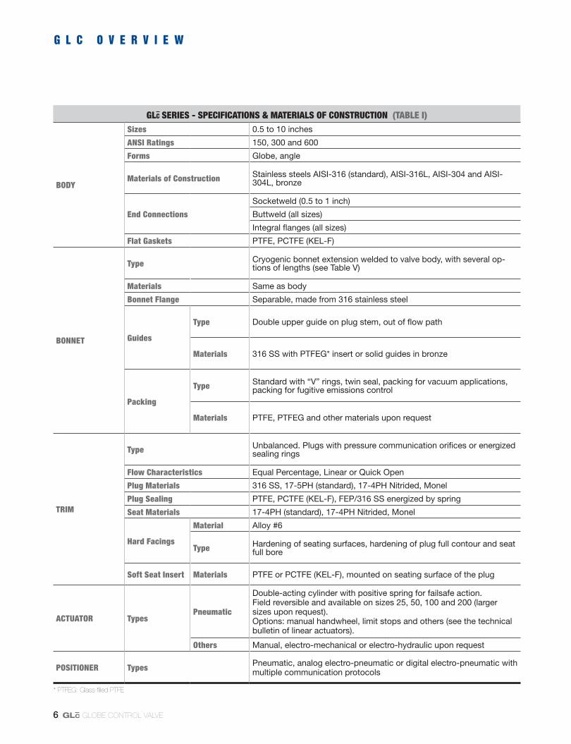
GLC SERIES - SPECIFICATIONS & MATERIALS OF CONSTRUCTION (TABLE I)
BODY
Sizes 0.5 to 10 inches
ANSI Ratings 150, 300 and 600
Forms Globe, angle
Materials of Construction Stainless steels AISI-316 (standard), AISI-316L, AISI-304 and AISI-304L, bronze
End Connections
Socketweld (0.5 to 1 inch)
Buttweld (all sizes)
Integral flanges (all sizes)
Flat Gaskets PTFE, PCTFE (KEL-F)
BONNET
Type Cryogenic bonnet extension welded to valve body, with several op-tions of lengths (see Table V)
Materials Same as body
Bonnet Flange Separable, made from 316 stainless steel
Guides
Type Double upper guide on plug stem, out of flow path
Materials 316 SS with PTFEG* insert or solid guides in bronze
Packing
Type Standard with “V” rings, twin seal, packing for vacuum applications, packing for fugitive emissions control
Materials PTFE, PTFEG and other materials upon request
TRIM
Type Unbalanced. Plugs with pressure communication orifices or energized sealing rings
Flow Characteristics Equal Percentage, Linear or Quick Open
Plug Materials 316 SS, 17-5PH (standard), 17-4PH Nitrided, Monel
Plug Sealing PTFE, PCTFE (KEL-F), FEP/316 SS energized by spring
Seat Materials 17-4PH (standard), 17-4PH Nitrided, Monel
Hard Facings
Material Alloy #6
Type Hardening of seating surfaces, hardening of plug full contour and seat full bore
Soft Seat Insert Materials PTFE or PCTFE (KEL-F), mounted on seating surface of the plug
ACTUATOR TypesPneumatic
Double-acting cylinder with positive spring for failsafe action. Field reversible and available on sizes 25, 50, 100 and 200 (larger sizes upon request).Options: manual handwheel, limit stops and others (see the technical bulletin of linear actuators).
Others Manual, electro-mechanical or electro-hydraulic upon request
POSITIONER Types Pneumatic, analog electro-pneumatic or digital electro-pneumatic with multiple communication protocols
* PTFEG: Glass-filled PTFE
G L C O V E R V I E W

GLc GLOBE CONTROL VALVE 7
% F
low
% Valve Stroke (Linear)
100
50
Equal PercentageThe Equal Percentage is the most common characteris-
tic used in processes control. The flow rate change by valve stroke unit is directly proportional to the flow rate passing through the valve at the moment immediately before the stroke movement. When installed, a valve with an Equal Percentage characteristic will present in most control loops, a characteristic close to the Linear characteristic, whenever the total differential pressure of the system is large com-pared to the differential pressure through the valve.
LinearThe Linear characteristic creates equal changes in
flow rate per unit of valve stroke, regardless of plug posi-tion. Linear plugs are frequently used in systems where the differential pressure through the valve corresponds to the major part of the total differential pressure of the system.
Quick-openQuick-open plugs are used in on-off services and are
designed to create large increments of flow rate, even from small opening percentages.
Trim SizesThere are three trim sizes available for the GLc Series
valves: standard trim, with full area; reduced trim, avail-able in a large range of sizes, and; trim with integral area, whose seat is machined in the valve body itself.
Alpha Anti-Cavitation TrimAlpha trim minimize the damage caused by fluid cavi-
tation, directing the turbulent liquid jets to the center of the plug and causing the implosion of the bubbles far from the metallic surfaces. Alpha trim uses a certain number of small holes diametrically opposed and carefully distrib-uted along the plug head.
As the plug is moving away from the seat, an increas-ing number of hole pairs are opened, and the cavitating jet of liquid that passes through each hole collides at the center of the plug head with the jet that enters through the opposite hole. The design of this special plug enables the creation of a non-cavitating fluid barrier around metal-lic surfaces, while moving away the pressure recovery area and the subsequent bubbles collapsing.
0 50 100
TYPICAL CONFIGURATIONS OF GLc VALVE PLUGS (FIGURE 8)
% F
low
% Valve Stroke (Equal Percentage)
100
50
0 50 100
Equal PercentageCharacteristic
LinearCharacteristic
Standard Contour Alpha
Standard Contour Alpha
F L O W C H A R A C T E R I S T I C S

GLc GLOBE CONTROL VALVE8
FLOW COEFFICIENTS (CV) VALVES WITH STANDARD TRIM (1) (TABLE II)
VALVE SIZE (inches)
TRIM SIZE (TN)
STROKE RATED Cv
in. mm =% Linear
0.5
0.38-20 (10-20) 0.75 19.05 2.5 2.5
0.38-18 (10-18) 0.75 19.05 1.95 1.95
0.38-16 (10-16) 0.75 19.05 1.48 1.48
0.25 (6.5) 0.75 19.05 1.10 1.10
0.12-12 (3.2-12) 0.50 12.70 0.51 0.51
0.12-10 (3.2-10) 0.50 12.70 0.30 0.30
0.75
1.00-30 (25-30) 0.75 19.05 9.1 9.1
1.00-28 (25-28) 0.75 19.05 6.0 6.0
1.00-26 (25-26) 0.75 19.05 4.1 4.1
0.38-20 (10-20) 0.75 19.05 2.5 2.5
0.38-18 (10-18) 0.75 19.05 1.95 1.95
0.38-16 (10-16) 0.75 19.05 1.48 1.48
0.25 (6.5) 0.75 19.05 1.10 1.10
0.12-12 (3.2-12) 0.50 12.70 0.51 0.51
0.12-10 (3.2-10) 0.50 12.70 0.30 0.30
1
1.00-30 (25-30) 0.75 19.05 15.5 15.5
1.00-28 (25-28) 0.75 19.05 11.9 11.9
1.00-26 (25-26) 0.75 19.05 9.1 9.1
1.00-24 (25-24) 0.75 19.05 6.0 6.0
1.00-22 (25-22) 0.75 19.05 4.1 4.1
0.38-20 (10-20) 0.75 19.05 1.95 1.95
0.38-18 (10-18) 0.75 19.05 1.48 1.48
0.38-16 (10-16) 0.75 19.05 1.10 1.10
0.25 (6.5) 0.75 19.05 1.00 1.00
0.12-12 (3.2-12) 0.50 12.70 0.51 0.51
0.12-10 (3.2-10) 0.50 12.70 0.30 0.30
1.5
1.50 (38) 1.00 25.4 34 34
1.25-38 (32-38) 1.00 25.4 30 30
1.25-36 (32-36) 1.00 25.4 15.2 15.2
1.25-34 (32-34) 1.00 25.4 11.9 11.9
1.25-32 (32-32) 1.00 25.4 6.1 6.1
FLOW COEFFICIENTS (CV) VALVES WITH STANDARD TRIM (1) (TABLE II-CONT.)
VALVE SIZE (inches)
TRIM SIZE (TN)
STROKE RATED Cv
in. mm =% Linear
2
2.00 (51) 1.50 38.1 64 64
1.63-50 (41-50) 1.50 38.1 47 47
1.63-48 (41-48) 1.50 38.1 30 30
1.63-46 (41-46) 1.50 38.1 21 21
1.63-44 (41-44) 1.50 38.1 15.3 15.3
1.63-42 (41-42) 1.00 25.4 11.6 11.6
3
2.63-60 (67-60) 2.00 50.8 115 115
2.63-58 (67-58) 2.00 50.8 79 79
2.63-56 (67-56) 2.00 50.8 61 61
2.63-54 (67-54) 2.00 50.8 30 30
4
3.50-70 (89-70) 2.50 63.5 226 226
3.50-68 (89-68) 2.50 63.5 194 194
3.50-66 (89-66) 2.50 63.5 132 132
3.50-64 (89-64) 2.50 63.5 121 121
3.50-62 (89-62) 2.50 63.5 60 60
6
4.00-76 (102-76) 3.00 76.2 399 399
4.00-74 (102-74) 3.00 76.2 261 261
4.00-72 (102-72) 3.00 76.2 200 200
8
7.44-82 (189-82) 4.00 101.6 859 859
7.44-80 (189-80) 4.00 101.6 601 601
7.44-78 (189-78) 4.00 101.6 516 516
10
9.75-88 (248-88) 4.00 101.6 1331 1331
9.75-86 (248-86) 4.00 101.6 995 995
9.75-84 (248-84) 4.00 101.6 795 795
(1) Consult VSI Controls to obtain information regarding the Cv of valves equipped with Quick-open trim.
F L O W C O E F F I C I E N T S

GLc GLOBE CONTROL VALVE 9
FLOW COEFFICIENTS, (CV) VALVES WITH ALPHA TRIM (1) (2) (TABLE III)
VALVE SIZE (inches)
TRIM SIZE (TN)
STROKE RATED Cv
in. mm =% Linear
0.5
0.75-20 (19-20) 1.00 25.4 9.1 9.9
0.75-18 (19-18) 0.75 19.05 7.0 8.1
0.75-16 (19-16) 0.75 19.05 6.0 6.1
0.75-14 (19-14) 0.75 19.05 3.9 4.0
0.75-12 (19-12) 0.75 19.05 2.5 2.5
0.75-10 (19-10) 0.75 19.05 1.51 1.51
0.75
0.75-20 (19-20) 0.75 19.05 9.1 9.9
0.75-18 (19-18) 0.75 19.05 7.0 8.1
0.75-16 (19-16) 0.75 19.05 6.0 6.1
0.75-14 (19-14) 0.75 19.05 3.9 4.0
0.75-12 (19-12) 0.75 19.05 2.5 2.5
0.75-10 (19-10) 0.75 19.05 1.51 1.51
1
0.75-20 (19-20) 0.75 19.05 9.1 9.9
0.75-18 (19-18) 0.75 19.05 7.0 8.1
0.75-16 (19-16) 0.75 19.05 6.0 6.1
0.75-14 (19-14) 0.75 19.05 3.9 4.0
0.75-12 (19-12) 0.75 19.05 2.5 2.5
0.75-10 (19-10) 0.75 19.05 1.51 1.51
1.5
1.25-26 (32-26) 0.75 19.05 9.7 9.9
1.25-24 (32-24) 0.75 19.05 6.0 6.1
1.25-22 (32-22) 0.75 19.05 3.9 4.0
FLOW COEFFICIENTS, (CV) VALVES WITH ALPHA TRIM (1) (2) (TABLE III-CONT.)
VALVE SIZE (inches)
TRIM SIZE (TN)
STROKE RATED Cv
in. mm =% Linear
2
1.63-34 (41-34) 2.00 50.8 39 45
1.63-32 (41-32) 1.50 38.1 34 34
1.63-30 (41-30) 1.00 25.4 24 24
1.63-28 (41-28) 1.00 25.4 15 16
1.25-26 (32-26) 0.75 19.05 9.7 9.9
1.25-24 (32-24) 0.75 19.05 6.0 6.1
1.25-22 (32-22) 0.75 19.05 3.9 4.0
3
2.50 (64) 2.00 50.8 71 91
2.25-44 (57-44) 1.50 38.1 46 64
2.25-42 (57-22) 1.50 38.1 43 43
1.88-40 (48-40) 1.00 25.4 28 29
1.88-38 (48-38) 1.00 25.4 15 16
1.50 (38) 0.75 19.05 10 10
4
3.00-54 (76-54) 2.00 50.8 95 96
3.00-52 (76-52) 2.00 50.8 65 66
1.88-50 (48-50) 1.50 38.1 43 44
1.88-48 (48-48) 1.50 38.1 28 29
6
4.75-62 (121-62) 3.00 76.2 311 351
4.75-60 (121-60) 2.50 63.5 194 241
4.75-58 (121-58) 2.50 63.5 159 160
3.25 (83) 2.00 50.8 111 111
(1) Alpha trim is not available with Quick-open characteristic. (2) Flow over is mandatory whenever Alpha trim is used (see additional information on technical brochure of severe service trim).

GLc GLOBE CONTROL VALVE10
A
B
C
ExtensionLenght
Match Line
(1) GLc valves equipped with plugs having pressure communication orifices should always be mounted with the extension and actuator within 15° of vertical. Actuators should be pointing up.(2) According to ANSI/ISA-75-08-05, last edition.
DIMENSIONS - GLOBE AND ANGLE VALVES(1) - ANSI CLASS 150, 300 & 600 (TABLE IV)
Valve Size (inches) ANSI Class
A(2) B C DClearance Required
Above Actuator for Disassembly
in. mm in. mm in. mm in. mm in. mm
0.5 150-600 8.00 203 3.80 97 1.77 45 6.8 173
0.75 150-600 8.25 210 3.80 97 1.75 44 6.8 173
1 150-600 8.25 210 3.80 97 1.75 44 4.25 108 6.8 173
1.5 150-600 9.88 251 3.93 100 2.31 59 4.75 121 8.9 226
2 150-600 11.25 286 4.06 103 2.25 57 5.75 146 9.1 231
3 150-600 13.25 337 5.34 136 3.39 86 7.00 178 11.3 287
4 150-600 15.50 394 6.06 154 5.22 133 8.75 222 14.1 358
6 150 20.00 508 6.04 153 5.48 139 8.88 226 16.1 409
6 300-600 20.00 508 8.19 208 5.75 146 11.0 279 18.2 462
8 150 24.00 610 6.94 176 7.08 180 13.0 330 20.0 508
8 300-600 24.00 610 8.75 222 7.48 190 13.0 330 21.8 554
10 150 29.62 752 7.37 187 8.44 214 21.4 544
10 300-600 29.62 752 7.37 187 8.93 227 21.4 544
ExtensionLenght
D
D
B
D I M E N S I O N S , E S T I M A T E D S H I P P I N G W E I G H T S
GLc GLOBE CONTROL VALVE 11
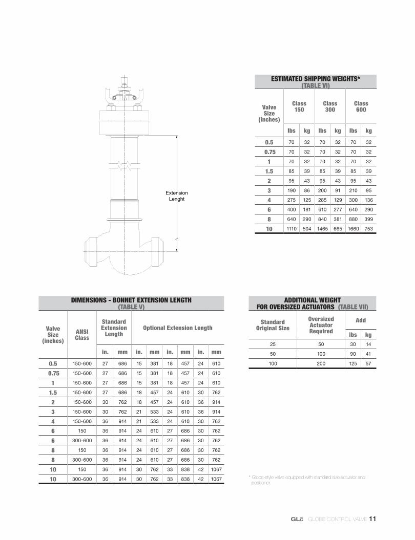
DIMENSIONS - BONNET EXTENSION LENGTH (TABLE V)
Valve Size
(inches)ANSI Class
Standard Extension
LengthOptional Extension Length
in. mm in. mm in. mm in. mm
0.5 150-600 27 686 15 381 18 457 24 610
0.75 150-600 27 686 15 381 18 457 24 610
1 150-600 27 686 15 381 18 457 24 610
1.5 150-600 27 686 18 457 24 610 30 762
2 150-600 30 762 18 457 24 610 36 914
3 150-600 30 762 21 533 24 610 36 914
4 150-600 36 914 21 533 24 610 30 762
6 150 36 914 24 610 27 686 30 762
6 300-600 36 914 24 610 27 686 30 762
8 150 36 914 24 610 27 686 30 762
8 300-600 36 914 24 610 27 686 30 762
10 150 36 914 30 762 33 838 42 1067
10 300-600 36 914 30 762 33 838 42 1067
ESTIMATED SHIPPING WEIGHTS* (TABLE VI)
Valve Size
(inches)
Class150
Class 300
Class600
lbs kg lbs kg lbs kg
0.5 70 32 70 32 70 32
0.75 70 32 70 32 70 32
1 70 32 70 32 70 32
1.5 85 39 85 39 85 39
2 95 43 95 43 95 43
3 190 86 200 91 210 95
4 275 125 285 129 300 136
6 400 181 610 277 640 290
8 640 290 840 381 880 399
10 1110 504 1465 665 1660 753
ADDITIONAL WEIGHT FOR OVERSIZED ACTUATORS (TABLE VII)
Standard Original Size
Oversized Actuator Required
Add
lbs kg25 50 30 14
50 100 90 41
100 200 125 57
ExtensionLenght
* Globe-style valve equipped with standard size actuator and positioner.
WorldWide presence through the Companies of the Group: italy - uk - the netherlands - norway - usa - brazil - singapore - australia - russia - kazakhstan
The information and specification contained in this bulletin are considered accurate. However, they are provided only for information purposes and should not be considered as certified. VSI Controls products are continuously improved and upgraded and the specification, dimensions and information contained herein are subject to change without notice. For further information or to confirm these presented here, contact your VSI Controls representative. The specific instructions for installation, operation and maintenance of the GLC control valve are provided in Maintenance Bulletin #08.