CRS960 - puzhaotech.compuzhaotech.com/userfiles/87.pdf · measurement Bosch, Denso, Delphi, Siemens...
55
CRS960 High Pressure Common Rail Control System Manual 2015-4 Copyright © 2005-2020 V1.01 get Latest version of Manual - http://doc.puzhaotech.com/ Important information Prior to start-up and operation of the equipment, be sure to read through this operating guidelines, especially to read the safety instructions to ensure your own safety, while avoiding the uncertainty of the situation in the use of the device, and to prevent damage to the device!
Transcript of CRS960 - puzhaotech.compuzhaotech.com/userfiles/87.pdf · measurement Bosch, Denso, Delphi, Siemens...
CRS960 High Pressure Common Rail Control System Manual
2015-4 Copyright © 2005-2020 V1.01 get Latest version of Manual - http://doc.puzhaotech.com/
Important information Prior to start-up and operation of the equipment, be sure to read through this operating guidelines, especially to read the safety instructions to ensure your own safety, while avoiding the uncertainty of the situation in the use of the device, and to prevent damage to the device!
Directory
Chapter I : Safety and maintenance 1.1 Safety Instructions 1.2 Use and maintenance
Chapter II : Overview 2.1 Introduction 2.2 Product Features
2.2.1 The high-pressure fuel rail test 2.2.2 Common Rail Injector Test 2.2.3 Common Rail Pump Test 2.2.4 User Interface and Interface
2.3 Test preparation and precautions before 2.3.1 Notes 2.3.2 Common Rail pump (CP) test preparation 2.3.3 Common Rail Injector (INJ) Test Preparation
Chapter III : Open and close 3.1 Open Systems 3.2 Shut down the system
Chapter IV : Control system interface definition 4.1 Interface Layout4.2 Controller Interface Description
Chapter V : Operating instructions 5.1 Overview 5.1.1 software interface 5.2 Basic Operations
5.2.1 Common Rail Injector Test 5.2.2 Pump injector / unit pump
5.2.3 Pump Test 5.2.4 Motor Test 5.2.5 Customer Management 5.2.6 System Settings interface 5.2.7 Device Diagnostics 5.2.8 Data Reporting and printing
Chapter VI : FAQ6.1 controller computer motherboard-related issues 6.2 Controller related issues

Chapter I :
Safety and maintenance
1.1 Safety Instructions
In order to ensure safe operation, please follow the following rules:
1. In the course of operation system, the operator should wear safety glasses and make sure that equipment, protective cover has been closed;
2. Ensure that the external three-phase alternating current is properly connected, power specifications to meet the requirements CRS960 common rail test bench, equipment enclosure grounded;
3. If the AC voltage is unstable, the device to be connected to the power regulator; 4. Make sure that the system is connected to the plug connection is correct, there can
be bad or short circuit with the housing, in particular injector plug after using it to avoid direct contact with the electrical terminals of the housing, or both terminals short-circuited to each other;
5. Make sure that the high-pressure pipe joints connected properly, no slippery silk, the leak. Run conditions were found to have leaks should immediately stop processing, and then test to find out why and rectification;
6. Regularly check the AC power cord is damaged, and whether the power plug or power outlet dust accumulation;
7. Be sure to plug in the connector plug operation shut down and turn off the power of the state, to avoid damage to static electricity or other external controller;
8. If the controller abnormal situation, or an abnormal sound or smell, smoke, pleasestop using the device and turn off the power guillotine;
9. The controller working environment temperature required between 0-35 degrees Celsius, and ensure good ventilation, avoid long hours working;
10.If the control system fails, please contact the service personnel to obtain the necessary assistance;
1.2 Use and maintenance
1. Do not throw, drop or treading bench, avoiding the controller by a strong external impact;
2. Do not put foreign objects into the internal test bed; 3. Do not allow water or other liquid into the controller; 4. Do not touch the cable terminal with wet hands; 5. Do not allow dust or foreign matter accumulate around the terminal of AC power,
the accumulation of dust on the AC terminals and foreign matter may cause a fire or electric shock;
6. Avoid walked on or pinched AC power cord; 7. Unplug the power cord when cleaning the test bench, the device needed to be
clean to boot after drying. 8. Also need regular long idle power operation, to ensure controller's internal
circuitry is not damp; 9. The device is placed in a dry, airy, sun, less dusty environments. 10. Regular replacement of diesel fuel and oil tank filter road.
Chapter II :
Overview
2.1 Introduction CRS960 (Common Rail System CRS960) common rail control system by controlling theoperation of the common rail test bench to complete the common rail pumps, common rail injector, high-pressure fuel rail test. Wide range of equipment, can be widely measurement Bosch, Denso, Delphi, Siemens and other common rail pump and injector, the injector system is equipped with more than 1600 injectors data, in maintenance and inspection can be used as a reference value or reference value, allowing users repair work more convenient. 2.2 Product Features CRS960 common rail control system components can be flexibly matching, to form different control platforms to meet the functional, cost, size, and many other needs, to achieve the highest price. In addition the device driver parameters can be flexibly adjusted to suit the pump and injector testing special models, ease of maintenance personnel working status Common Rail System judge and maintenance. The system can also be extended, such as centralized management of multiple devices, unified data reporting, especially for common rail device manufacturers batch testing. 2.2.1 The high-pressure fuel rail test
1. provide Bosch, pre-calibrated value Delphi, Denso, JIER rail pressure sensor 2. users can add new sensor type oil pump, and a pressure sensor for different
display value recalibration 3. rail pressure automatic control 4. rail pressure is too high will active the automatic protection
2.2.2 Common Rail Injector Test
1. Measure up to 6-channels solenoid valve injector• High Voltage - Bosch, Denso injector
• Low Voltage - Delphi injector
2. Measure 1 channel Siemens, Bosch piezoelectric crystal (PIEZO) Injector 3. all channels solenoid and piezoelectric crystal drive with short circuit protection,
will not damage the controller and measured injector 4. provide standard test steps and conditions for each standard fuel injection and
back data, synchronized display. Users can also customize the working steps, add or change the experimental data, the system comes with more than 1,600 pieces ofstandard data (and in continuous update)
2.2.3 Common Rail Pump Test
1. multi-channel PWM (pulse width modulation signal) for driving the pumps; • single-channel pump drive signal adjustment
• Bosch CP1 / CP2 / CP3
2. Delphi CRSP 3. Denso HP3 / HP4 4. drive a road DRV, designed to test the ability to pump oil pump 5. two separate drives combine Denso HP0 pump (ECD-U2) speed sensor on the
timing signal, synchronized Control HP0 two oil pump control solenoid valve; 6. All channel drivers with short circuit protection, will not damage the controller
and test the pump; 7. provide standard test steps and conditions for each standard fuel pump data,
synchronized display. Users can also customize the working steps, add or change the experimental data.
2.2.4 User Interface and Interface
1. Support 10-inch / 15-inch / 17-inch / 19-inch touch-screen operation; 2. Multi-language-friendly interface display, user-friendly operation; 3. Real-time working status feedback, allowing users to make decisions faster;
4. powerful database management features more than 1,600 injectors standard data; 5. can be accessed by a standard keyboard and mouse; 6. equipped with ultra-compact industrial computer, SSD solid state drive for data
backup, system software updates and data upgrade; 7. system functions cropping flexibility can be combined into a variety of control
systems; 8. precision digital dipstick to ensure test accuracy; 9. Different injector with a different adapter, connects users to a different injector
2.3 Test preparation and before precautions 2.3.1 Notes
In the case of the device is powered, non-swap CRS960 control system plug and the connecting cable, the control system may cause damage or loss of data, so that the device can not run. Should connect the device to check before energizing the system is correct, confirmation and then do the following steps.
1. before the pump is installed to clean the pump. 2. before installation the injector make sure its cleaned. 3. external damage in time to check the pump.
! Strictly prohibited damaged pump mounting up for testing. 4. installing the pump to the test bench.
! Using special clamps and couplings for this operation. 2.3.2 Common Rail pump (CP) test preparation
1. Connect high-pressure hose; 2. Connect the oil supply line; 3. Connect the return / overflow tube; 4. Use a dedicated cable oil pump connected to the pump control valve; 5. Double standards pressure sensor, DRV valve; 6. Close all safety guards; 7. Set the motor speed, direction;
8. Set the rail pressure; 9. Configure other required parameters to start measuring.
2.3.3 Common Rail Injector (INJ) Test Preparation
1. High-pressure hose connected to the injector; 2. Injector electrical connector joints; 3. Connector Injector pipe, return pipe; 4. Close all safety guards; 5. Setting conditions to start measuring the measurement mode is selected.

Chapter III :
Open and close
To ensure safe and reliable operation and safety of your operator switching operating systems in the following way. 3.1 Open Systems
1. Ensure that the test device master switch in the OFF state drop-down 380V AC knife;
2. Check the device is turned on without exception total device power switch; 3. Wait for the system to start, it normally takes two minutes or so; 4. After the system starts, CRS960 control software will automatically start.
To comply with the provisions of the prevention of accidents! When the danger to decisively cut off the main switch! 3.2 Shut down the system
Before using the main switch off the device power, make sure your test data has beensaved.
Chapter IV :
Control system interface definition
Because the system contains high and low voltage lines mixed wired and precision components, system is connected to the device, be sure that the wiring is accurate, avoid wiring errors and damage personal, equipment and systems. If you have questions during assembly, please contact our service personnel, the company is not responsible for damage to persons, equipment, systems due to human negligence. When to get control system, front electrical cable assembly equipment, be sure to refer to this assembly drawing. System accessories are subject to change and the company does not guarantee the consistency of the interface, is subject to change, we will update the document, refer to the latest document assembly. 4.1 Dashboard Interface 4.1.1 Interface Description Dashboard (this figure may be published separately, please contact us for)
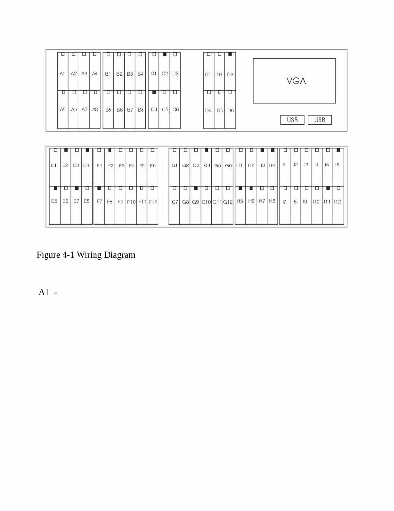
Figure 4-1 Wiring Diagram A1 -
Chapter V :
Operating instructions
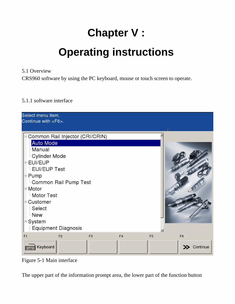
5.1 Overview CRS960 software by using the PC keyboard, mouse or touch screen to operate. 5.1.1 software interface
Figure 5-1 Main interface The upper part of the information prompt area, the lower part of the function button
area, central to specific functional areas. 5.2 Basic Operations 5.2.1 Testing Injector A, automatic mode The main interface choose injector test - automatic mode, click Continue to enter. Then the selected injector model, the database there is no similar model can be used to build a new data model or to do the test. After selecting the button there is dialog box pops up, you can use the search mode or drag the slider to select. Search mode displays only matching model injector, if you want to show all injectors, you can click a button. After selecting the press continues to be recognized.
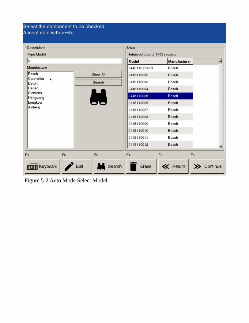
Figure 5-2 Auto Mode Select Model
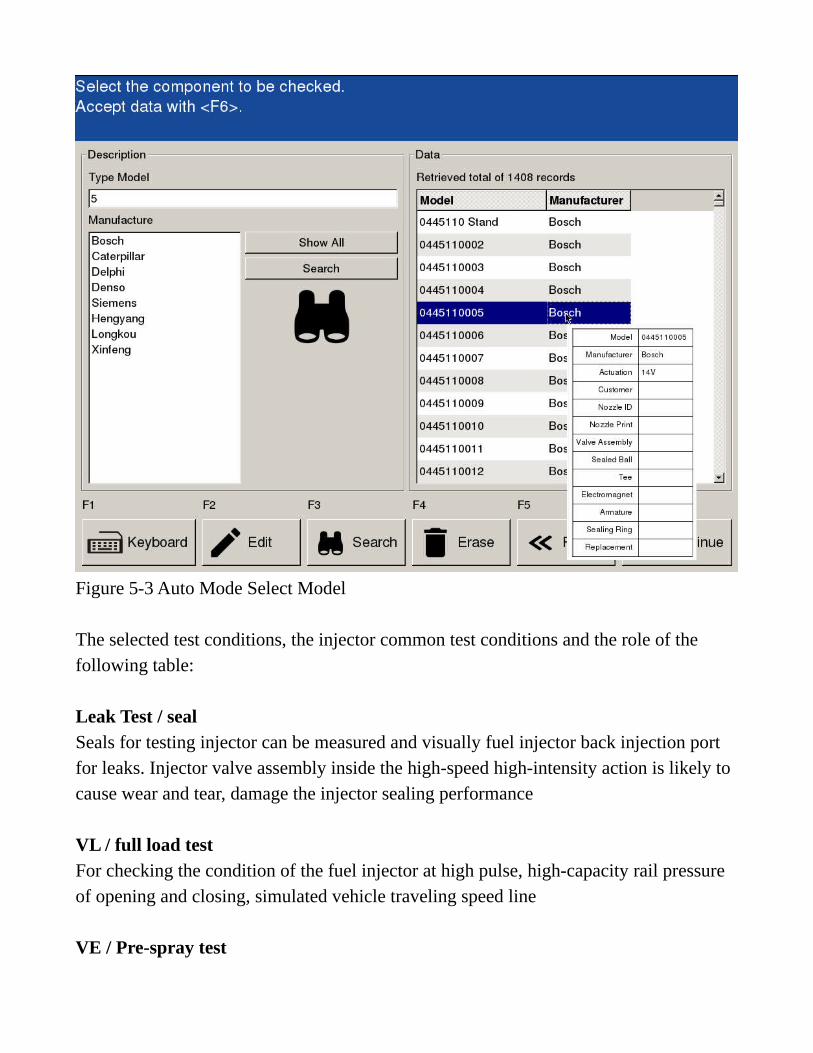
Figure 5-3 Auto Mode Select Model The selected test conditions, the injector common test conditions and the role of the following table: Leak Test / seal Seals for testing injector can be measured and visually fuel injector back injection port for leaks. Injector valve assembly inside the high-speed high-intensity action is likely to cause wear and tear, damage the injector sealing performance
VL / full load test For checking the condition of the fuel injector at high pulse, high-capacity rail pressure of opening and closing, simulated vehicle traveling speed line
VE / Pre-spray test
For detecting injector low pulse, the ability to open and close the high rail pressure, and can measure injector open time
LL / idle test For detecting the pressure of the fuel injector in LEO opening and closing of the ability to simulate the situation when a car idling.
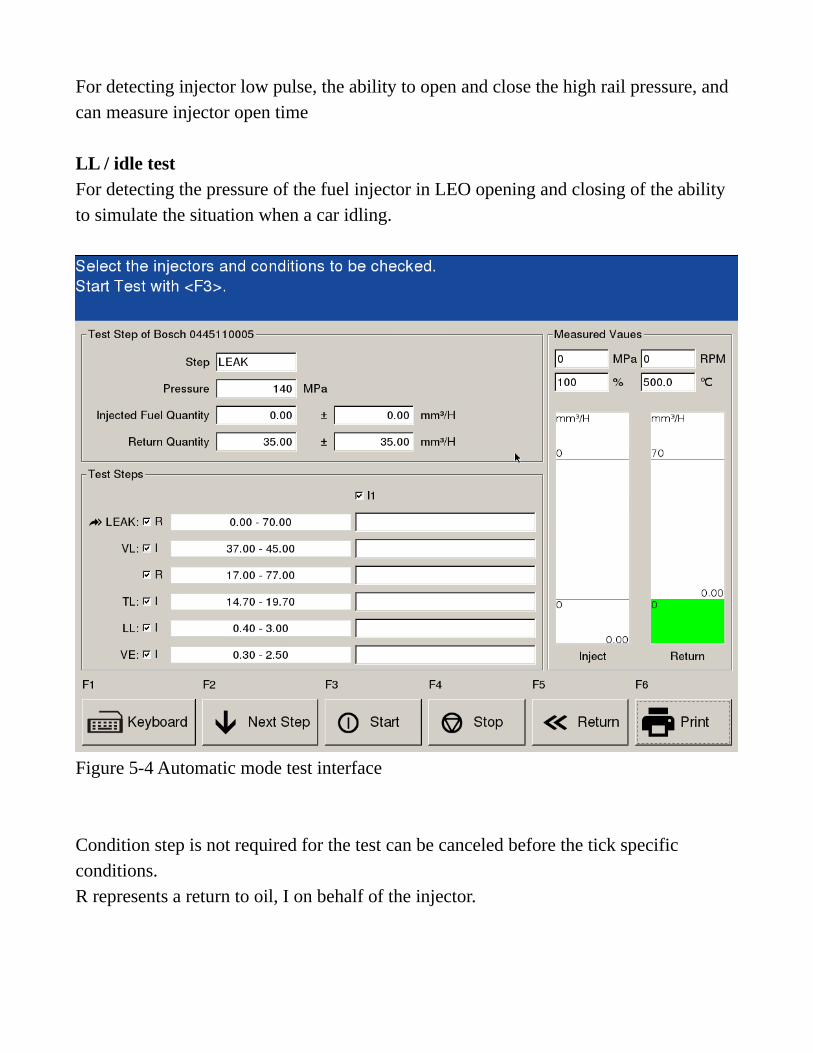
Figure 5-4 Automatic mode test interface Condition step is not required for the test can be canceled before the tick specific conditions. R represents a return to oil, I on behalf of the injector.
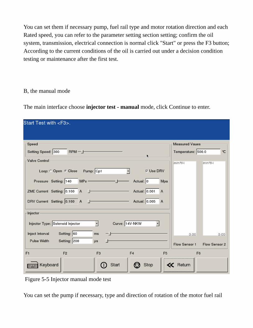
You can set them if necessary pump, fuel rail type and motor rotation direction and each Rated speed, you can refer to the parameter setting section setting; confirm the oil system, transmission, electrical connection is normal click "Start" or press the F3 button;According to the current conditions of the oil is carried out under a decision condition testing or maintenance after the first test. B, the manual mode The main interface choose injector test - manual mode, click Continue to enter.
Figure 5-5 Injector manual mode test You can set the pump if necessary, type and direction of rotation of the motor fuel rail
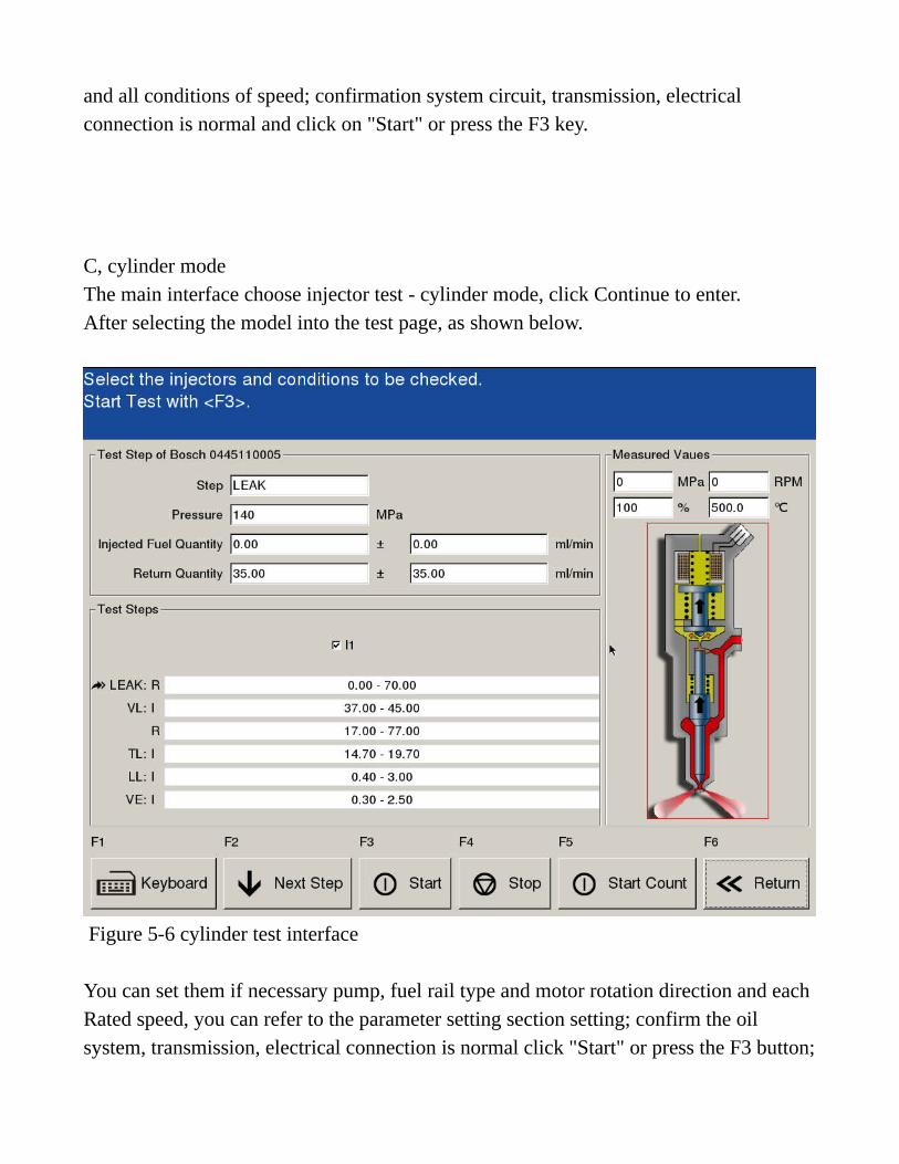
and all conditions of speed; confirmation system circuit, transmission, electrical connection is normal and click on "Start" or press the F3 key. C, cylinder mode The main interface choose injector test - cylinder mode, click Continue to enter. After selecting the model into the test page, as shown below.
Figure 5-6 cylinder test interface You can set them if necessary pump, fuel rail type and motor rotation direction and each Rated speed, you can refer to the parameter setting section setting; confirm the oil system, transmission, electrical connection is normal click "Start" or press the F3 button;
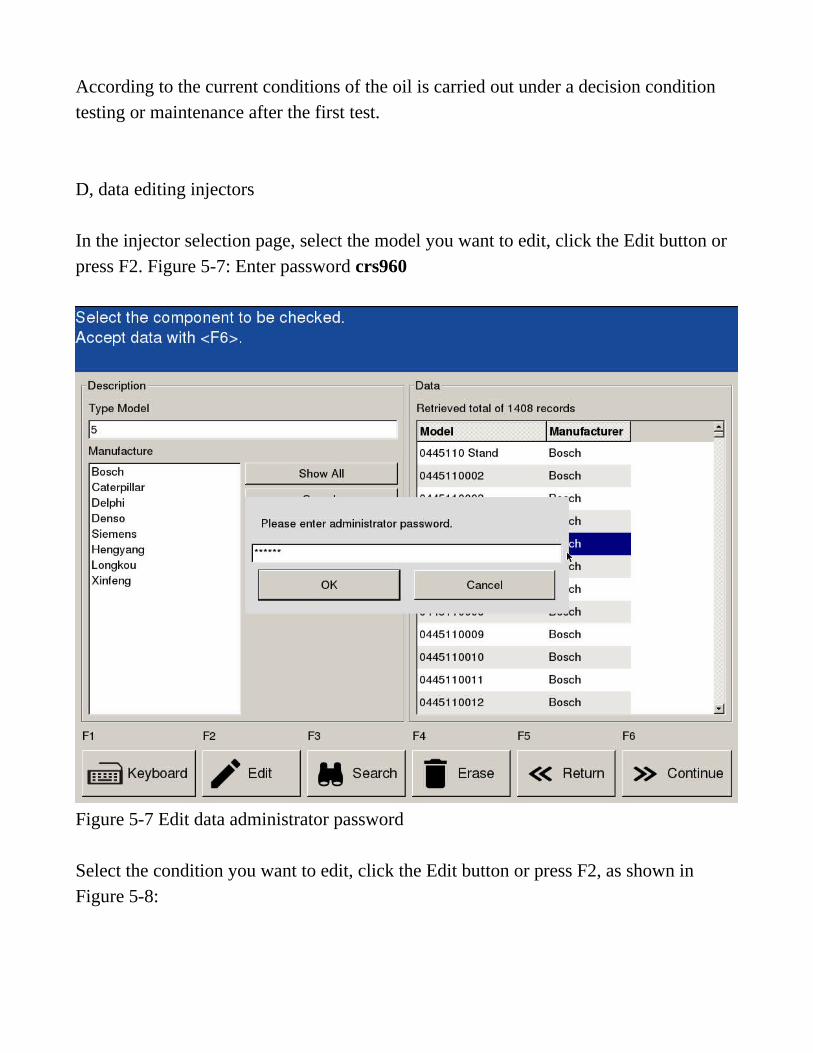
According to the current conditions of the oil is carried out under a decision condition testing or maintenance after the first test. D, data editing injectors In the injector selection page, select the model you want to edit, click the Edit button or press F2. Figure 5-7: Enter password crs960
Figure 5-7 Edit data administrator password Select the condition you want to edit, click the Edit button or press F2, as shown in Figure 5-8:
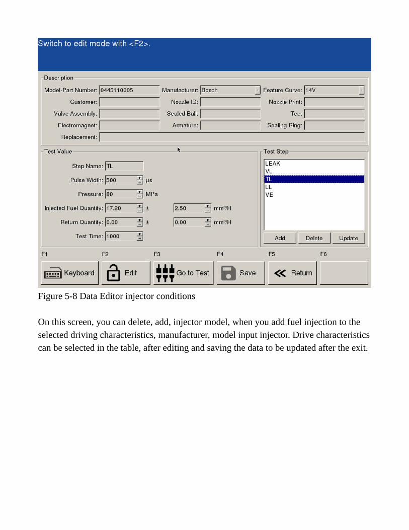
Figure 5-8 Data Editor injector conditions On this screen, you can delete, add, injector model, when you add fuel injection to the selected driving characteristics, manufacturer, model input injector. Drive characteristicscan be selected in the table, after editing and saving the data to be updated after the exit.
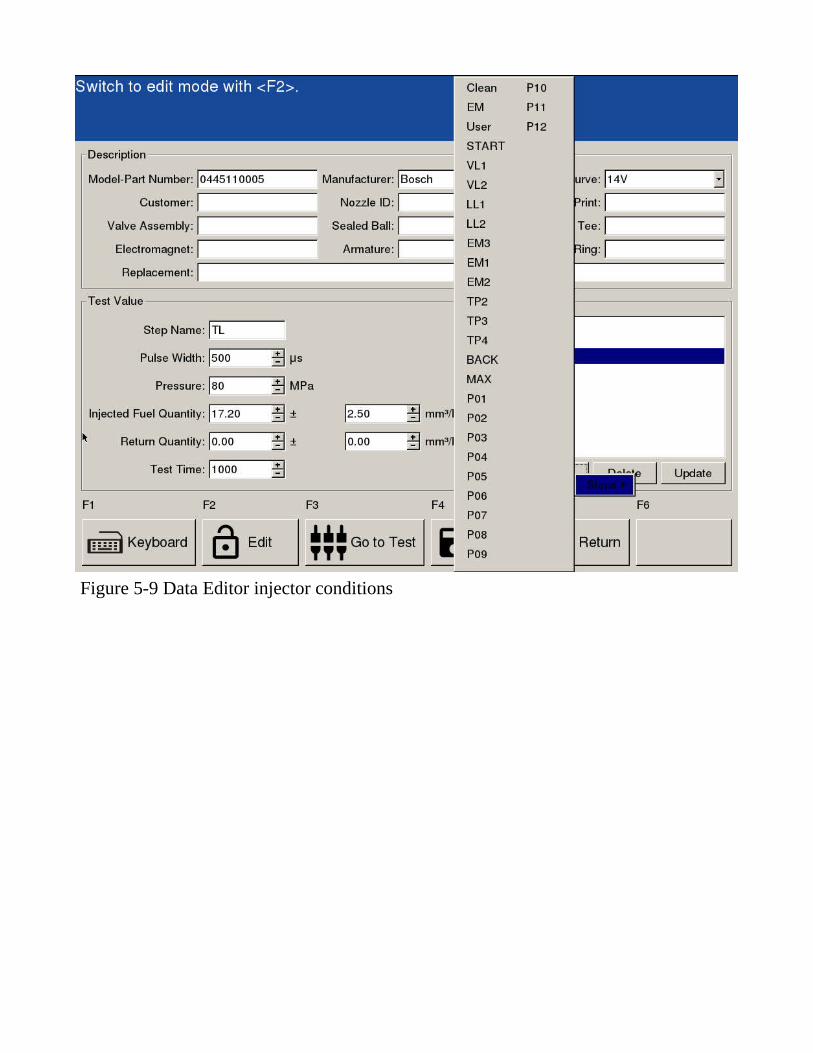
Figure 5-9 Data Editor injector conditions
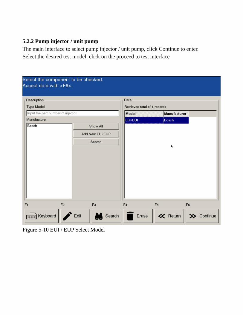
5.2.2 Pump injector / unit pump The main interface to select pump injector / unit pump, click Continue to enter. Select the desired test model, click on the proceed to test interface
Figure 5-10 EUI / EUP Select Model
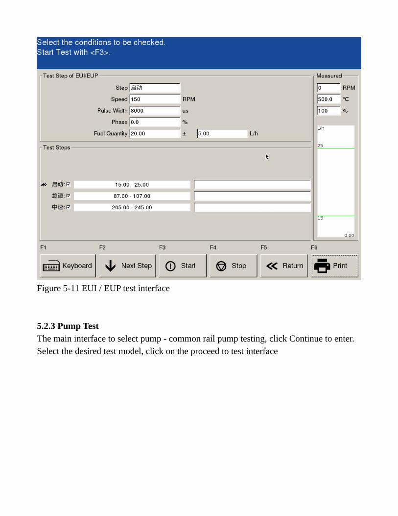
Figure 5-11 EUI / EUP test interface
5.2.3 Pump Test The main interface to select pump - common rail pump testing, click Continue to enter. Select the desired test model, click on the proceed to test interface

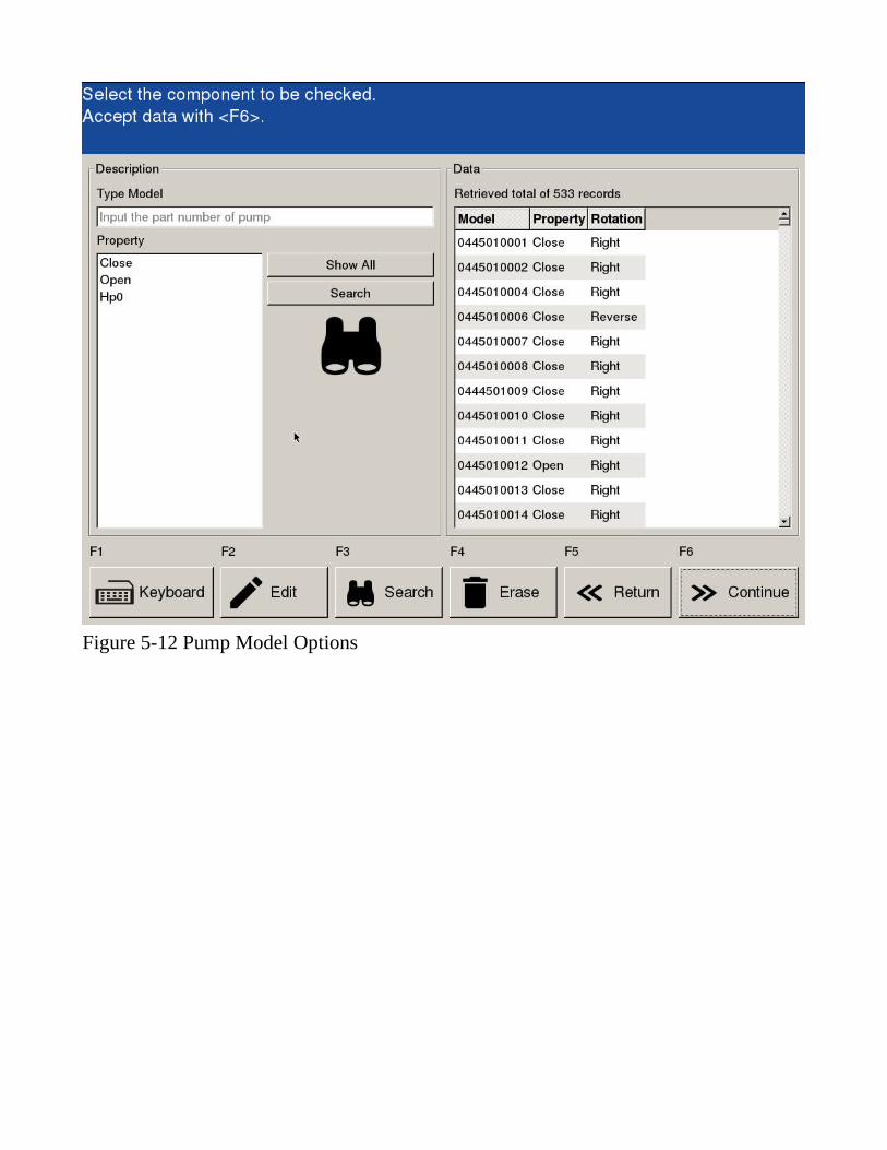
Figure 5-12 Pump Model Options
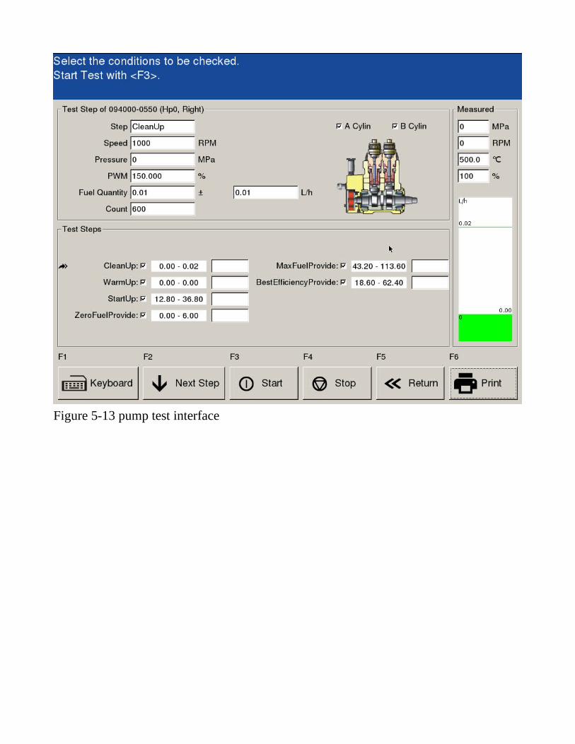
Figure 5-13 pump test interface
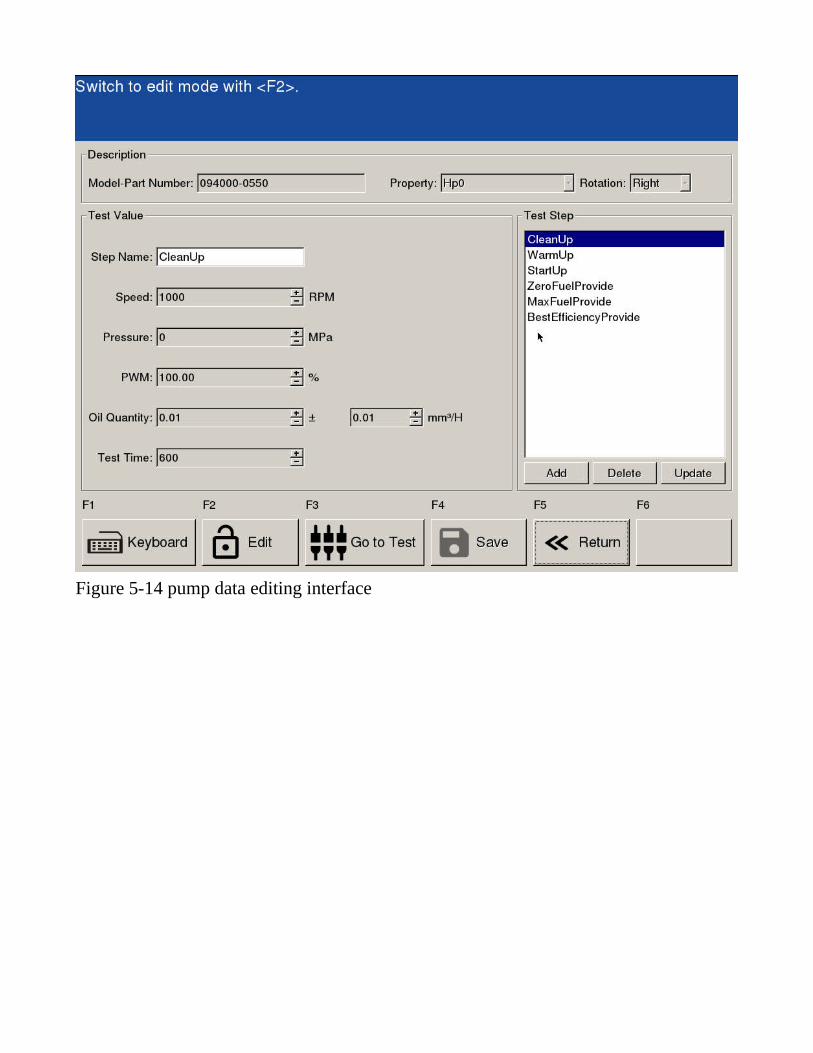
Figure 5-14 pump data editing interface
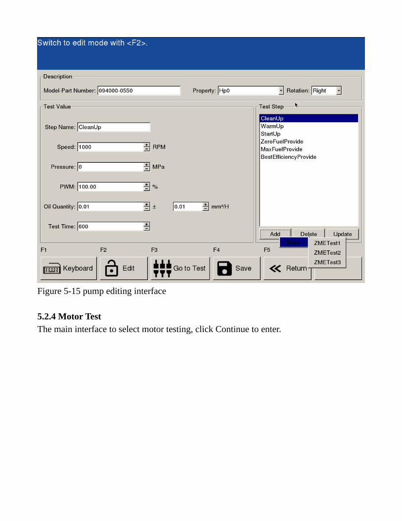
Figure 5-15 pump editing interface
5.2.4 Motor Test The main interface to select motor testing, click Continue to enter.


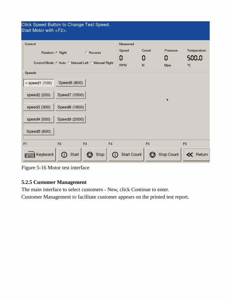
Figure 5-16 Motor test interface
5.2.5 Customer Management The main interface to select customers - New, click Continue to enter. Customer Management to facilitate customer appears on the printed test report.

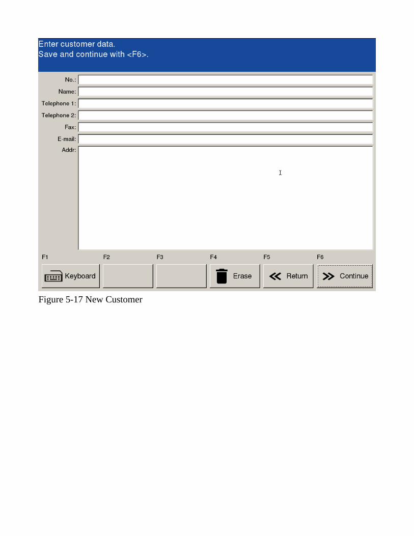
Figure 5-17 New Customer
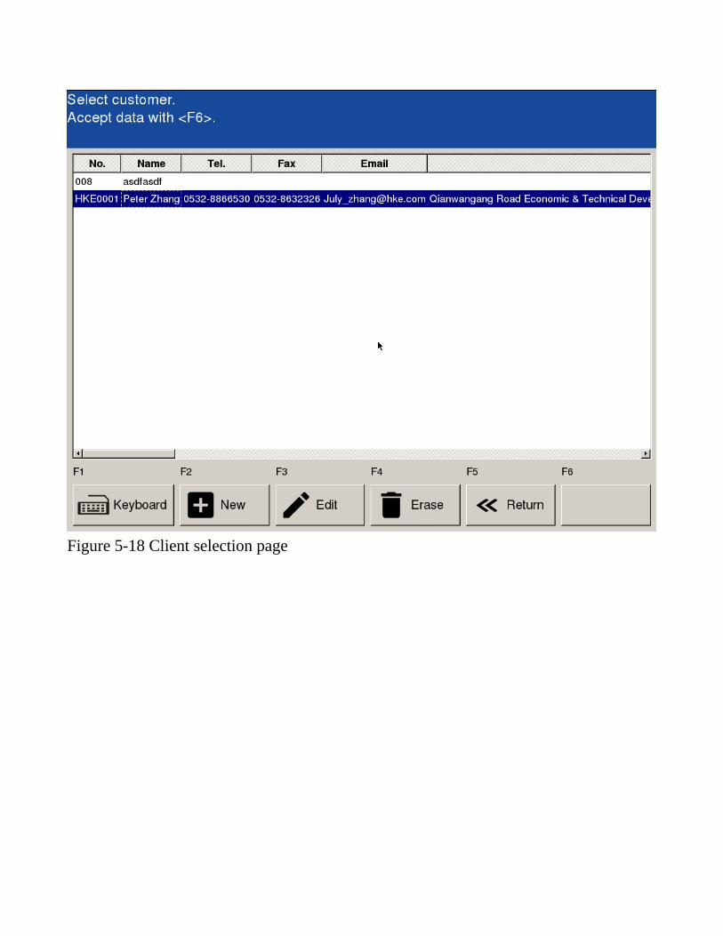
Figure 5-18 Client selection page


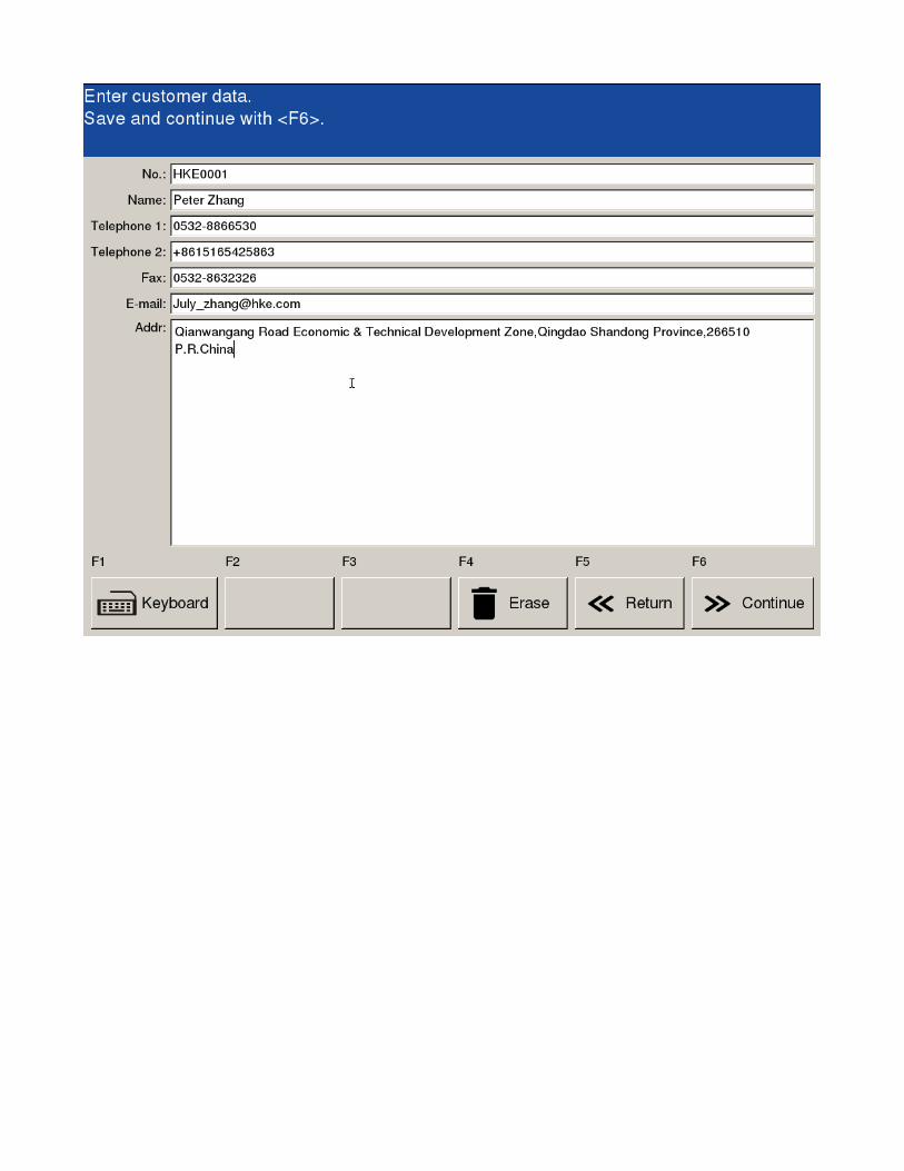
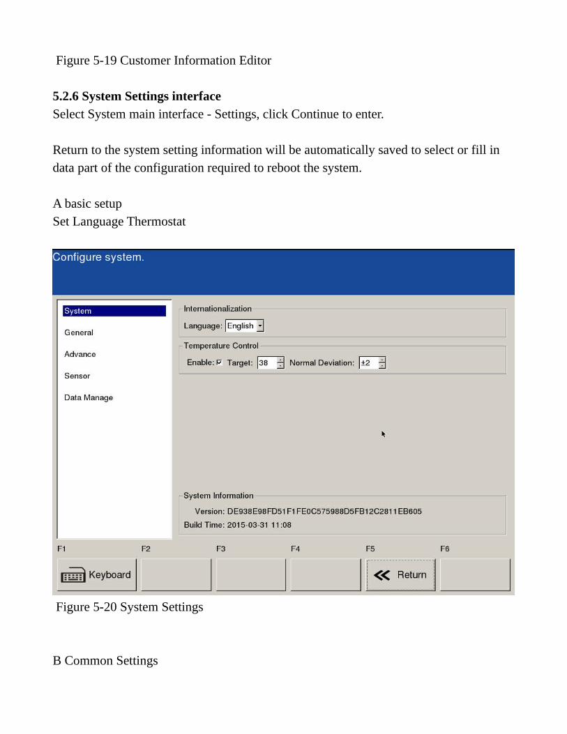
Figure 5-19 Customer Information Editor
5.2.6 System Settings interface Select System main interface - Settings, click Continue to enter. Return to the system setting information will be automatically saved to select or fill in data part of the configuration required to reboot the system. A basic setup Set Language Thermostat
Figure 5-20 System Settings B Common Settings

Set the serial type pump motor steering system time Printer Remote Assistance and data backup and recovery


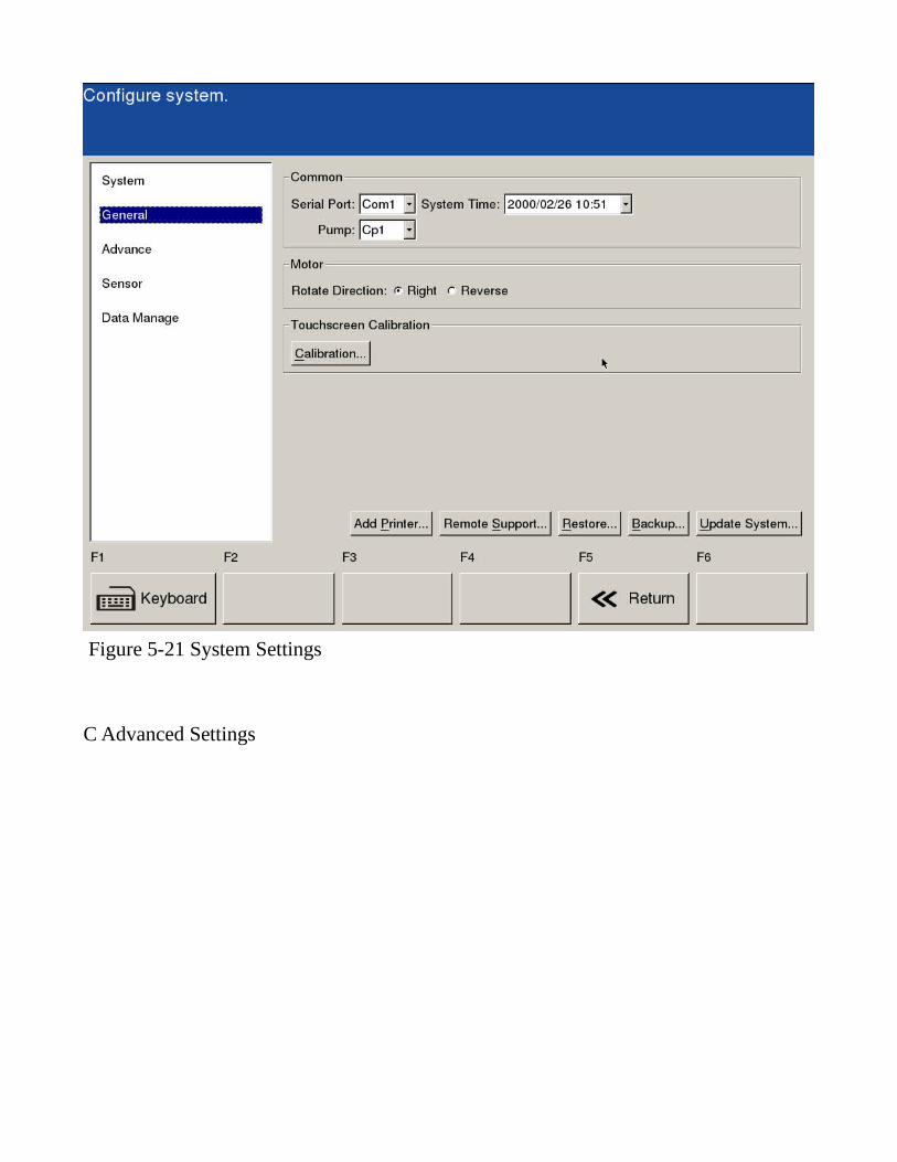
Figure 5-21 System Settings C Advanced Settings
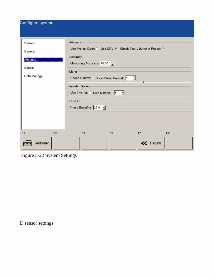
Figure 5-22 System Settings
D sensor settings
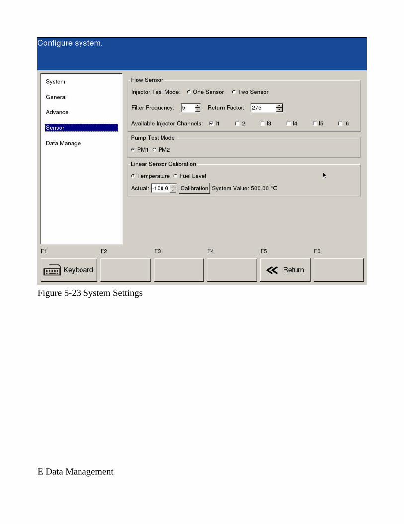
Figure 5-23 System Settings
E Data Management
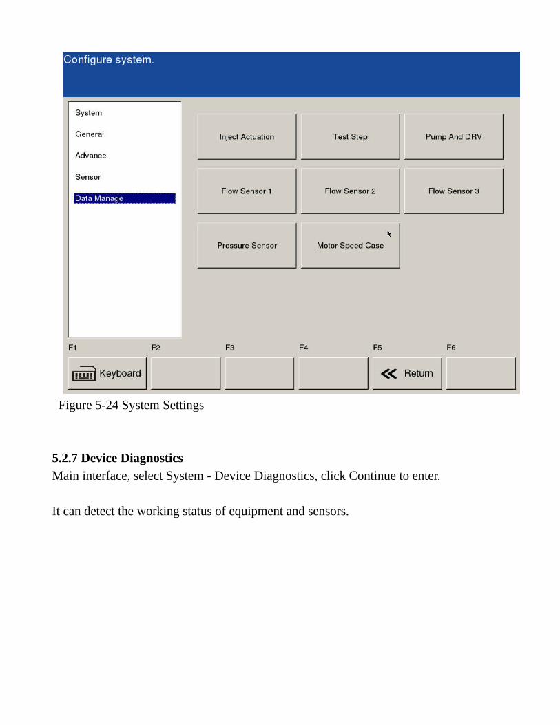
Figure 5-24 System Settings
5.2.7 Device Diagnostics Main interface, select System - Device Diagnostics, click Continue to enter. It can detect the working status of equipment and sensors.
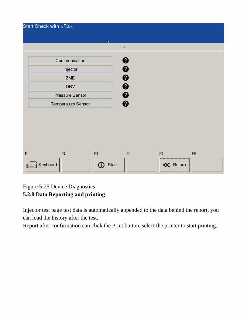
Figure 5-25 Device Diagnostics 5.2.8 Data Reporting and printing Injector test page test data is automatically appended to the data behind the report, you can load the history after the test. Report after confirmation can click the Print button, select the printer to start printing.
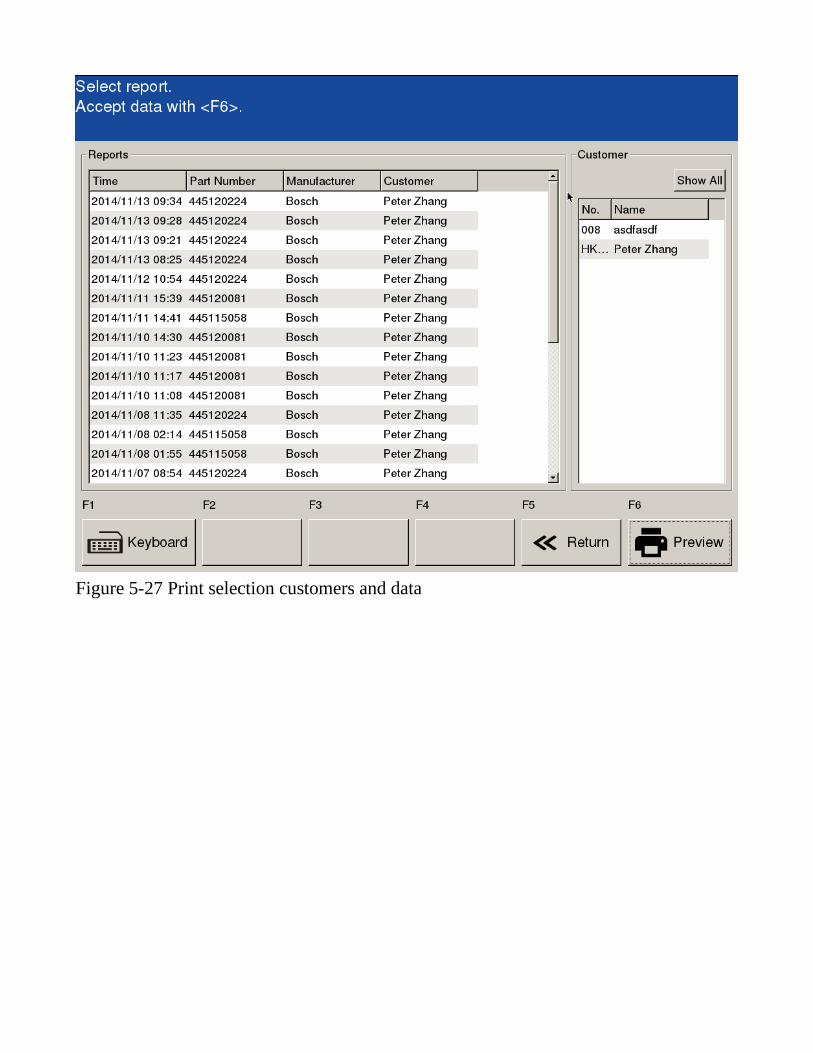
Figure 5-27 Print selection customers and data
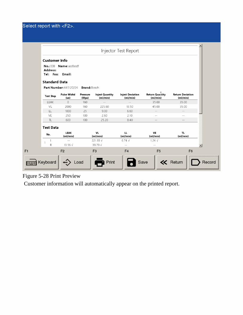
Figure 5-28 Print Preview Customer information will automatically appear on the printed report.
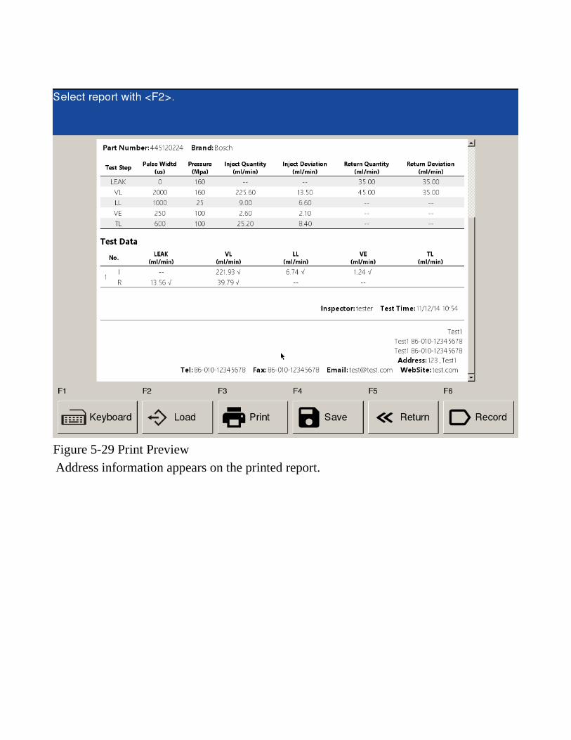
Figure 5-29 Print Preview Address information appears on the printed report.
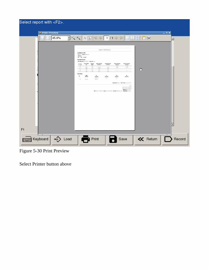
Figure 5-30 Print Preview Select Printer button above
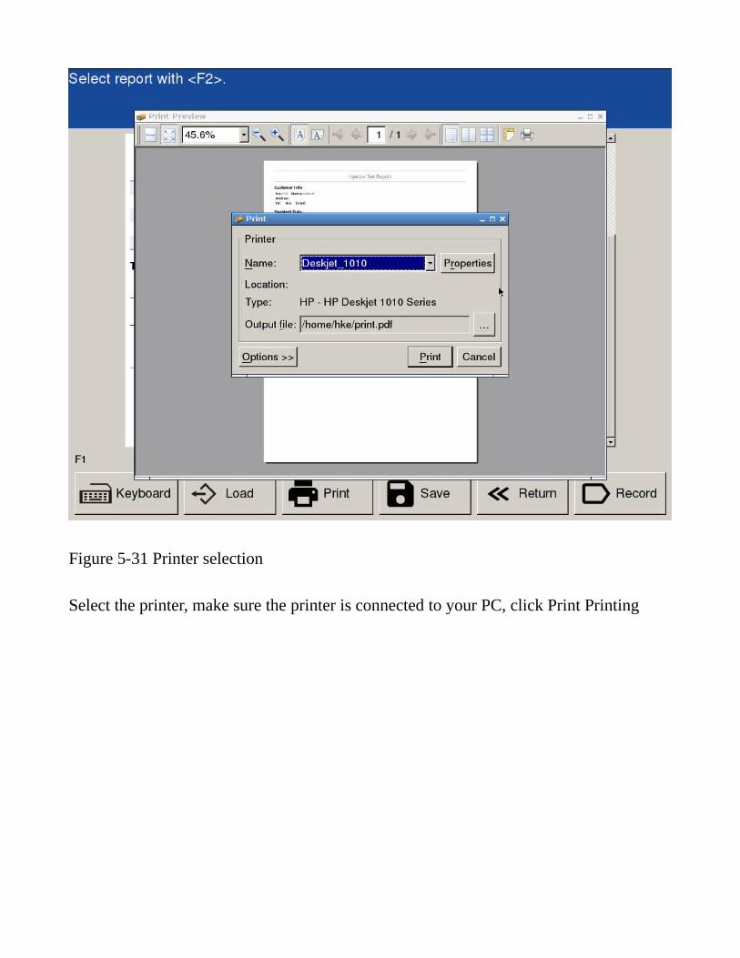
Figure 5-31 Printer selection Select the printer, make sure the printer is connected to your PC, click Print Printing

Chapter VI :
FAQ
6.1 controller computer motherboard-related issues After a turn on the system display a black screen
1. Check the controller power supply is normal, light on; 2. Check the monitor power light is lit, the monitor connector on the computer is
plugged;
6.2 Controller related issues 1.the control panel power indicator is off
Check control power output and power supply box inside 24V is normal, the input is AC 220V, deviation +/- 20V, output is DC 24V, the voltage deviation is greater than +/- 0.5V considered abnormal.
2. Communication is not normal Check the control panel COM1 5-pin serial line port is plugged in, if necessary, reseated after power failure.
3. The injector is not working Check the control panel COMMON RAIL jack plug is not plugged in, the fuel injector electrical connector end is normal, with or without open circuit
Check injector resistance is normal, normal injector resistance around 0.2Ω. Resistance table below for reference purposes only BOSCH 0.15Ω-0.4Ω DENSO 0.2Ω-0.4Ω
DELPHI 0.05Ω-0.2Ω 4. The pump proportional valve does not work properly ■ For the purposes of the common rail high pressure pumps CP1 DRV: pressure control valve EAV: element shut-off valve ■ For the purposes of the common rail high pressure pump CP2 DMV: solenoid valve ■ For the purposes of the common rail high pressure pumps CP3 ZME: metering valve
In DRV-free valve system, pump proportional valve control is a key component of the system pressure, the solenoid valve is not working or not working properly can cause rail pressure spikes, rail pressure instability, the rail pressure can not rise and so on. A, check the control panel COMMON RAIL jack plug is not plugged in; B, proportional valve plug on the pump have not plugged in; C, check the controller power supply is normal; Under D, the stop state start, adjust proportional valve control output PWM value, different position proportional valve on the pump should be different voices; E, above no exception can check proportional valve is blocked, the wear and the like.
5. The rail pressure no display or display is not normal A, rail pressure has been 0: ■ different track rail pressure sensor connector is different, there are different line sequence, check the rail pressure sensor connector is correctly ■ Check that the controller port connector plugged COMMON RAIL B, rail pressure to a fixed value does not fluctuate: ■ different track rail pressure sensor connector is different, there are different line sequence, check the rail pressure sensor connector is correctly ■ Check that the control panel connector ports plugged COMMON RAIL C. rail pressure and the actual value deviations: ■ rail pressure sensor parameters to adjust the system, are not allowed to adjust thelow end of the low pressure and high pressure are not allowed to adjust the high end.
6. speed no display or display is not normal
■ Check the Hall sensor is correctly installed, when rotating light blink? ■ Check the control panel SENSOR jack plug is not plugged in ■ Check the inverter control cable is connected properly ■ Check the drive controller is not close to strong interference sources such as motor. 7. The speed control is not normal ■ Check that the control panel SENSOR port plug good ■ Check the inverter control cable is connected properly ■ Check the drive controller is near strong interference sources such as motor. 8. The fuel injector is small, especially the pre-ejection state ■ Check whether the abnormal injector ■ with normal pre-injector check the injector spray of sound, to see if normal ■ check the actual rail pressure there is no deviation, whether small 9. manually adjust the speed does not work ■ Check that the control panel MOTOR port plug good ■ Check the manual adjustment potentiometer is connected correctly ■ screen operations have not switched to manual mode, the control panel should have a relay switching hop sound ■ Adjust the manual knob inverter displays the output value has not changed 10. The protective door switch signal is not normal ■ Check the control panel MOTOR jack plug is not plugged in ■ Check the proximity switch is not normally open NPN type ■ Check whether the proximity switch is working properly, close to the metal, the light should come on 11. Click "" that the protection ■ Check that the injector normal resistance, whether short circuit ■ Check equipment for leaks ■ Check that the control box 24V Power Good 12. The serial line or other traces fever or other abnormal ■ Check the line connection ■ Check equipment for leaks