CR/PS - Implamed
36
Operative Technique CR/PS CRUCIATE RETAINING POSTERIOR STABILIZED
Transcript of CR/PS - Implamed

Operative Technique
CR/PSCruCiate retaining
posterior stabilized

TABLE OF CONTENTSINTRODUCTION...........................................................................................1DESIGN RATIONALE.....................................................................................1OPERATIVE TECHNIQUE OVERVIEW..........................................................2DETAILED OPERATIVE TECHNIQUE............................................................4 PRE-OPERATIVE PLANNING................................................................4 APPROACH AND EXPOSURE...............................................................4 PREPARATION OF THE FEMUR............................................................ 5 OpeningoftheIntra-medullaryCanal..........................................5 FemoralAlignmentAssembly.......................................................5 InstrumentSetup....................................................................5 ResectionofDistalFemoralBone.................................................6 RecuttingtheDistalFemur.....................................................7 SizingoftheFemoralComponent................................................7 EstablishmentofRotationofFemoralComponent.....................7 ResectionofAnterior,PosteriorandChamferFemoralBone.....8 POSTERIOR STABILIZED FEMORAL PREPARATION...........................9 PREPARATION OF THE TIBIA................................................................ .9 EXTRA-MEDULLARY ALIGNMENT.......................................................9 PlacementandDistalAlignmentofthe
Extra-medullaryTibialAlignmentGuide......................................9 InstrumentSetup....................................................................9 ProximalAlignment..................................................................... 11 DeterminationofTibialResectionDepth.................................... 11 SecuringTibialResectionGuidetoTibiaand
FinalChecking...............................................................................12 INTRA-MEDULLARY ALIGNMENT......................................................13 OpeningoftheIntra-medullaryCanal........................................13 AssemblyandPlacementofIMAlignmentGuide.....................14 InstrumentSetup..................................................................14 GuideAlignmentandStabilization.............................................14 DeterminationofTibialResectionDepth....................................14 PinningofTibialResectionGuide,RemovalofIM
AlignmentGuideandFinalChecking.........................................15 ProximalTibialBoneResection...................................................16 PLACEMENT AND SIZING OF TRIAL COMPONENTS...................... 17 PREPARATION OF THE PATELLA........................................................17 ResectionofthePatellarArticularSurface.................................17 Free-HandResection.............................................................17 UsingthePatellarResectionGuide.....................................18 FinalSizingandDrillingofthePatella........................................ 19 PatellarTrialPlacement................................................................ 19 FINAL PROSTHESIS TRIAL CHECK.....................................................20 AlignmentCheck..........................................................................20 StabilityCheck..............................................................................20 MotionCheck................................................................................21 PatellarTrackingCheck.................................................................21 FINAL BONE PREPARATION: FEMUR................................................22 FemoralPegHolePreparation....................................................22 FINAL BONE PREPARATION: TIBIA.....................................................22 FixationofTibialTrayTrial............................................................22 DrillingtheCentralCavity........................................................... .22 TampingforTibialStem...............................................................22 PROSTHESIS IMPLANTATION............................................................24 FinalBonePreparation................................................................24 ImplantationofTibialProsthesis.................................................24 ImplantationofFemoralComponent.........................................26 ImplantationofPatellarComponent...........................................26 PolymerizationofCement...........................................................27 InstallationofTibialPolyethyleneInsert.....................................27FINAL CHECK AND CLOSURE....................................................................27INSTRUMENT LISTING..............................................................................28
2
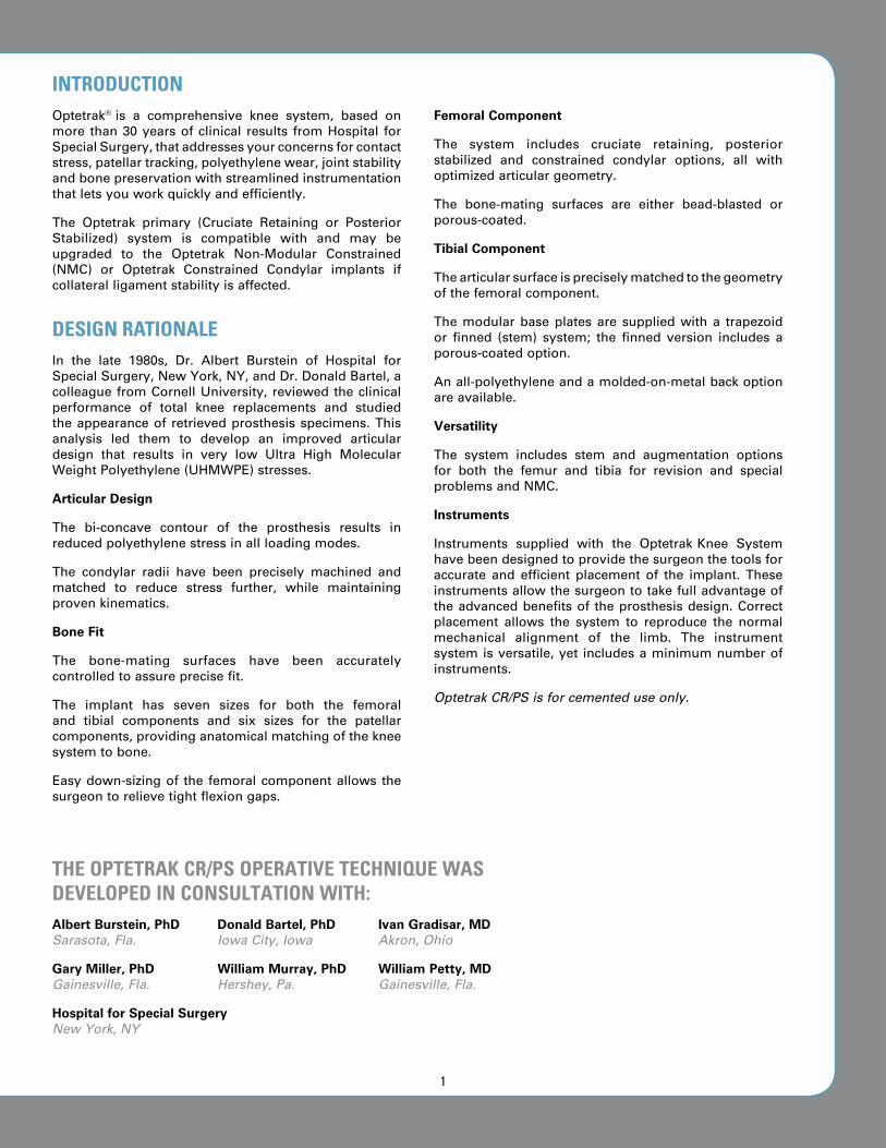
Optetrak® is a comprehensive knee system, based onmore than30yearsofclinical results fromHospital forSpecialSurgery,thataddressesyourconcernsforcontactstress,patellartracking,polyethylenewear,jointstabilityandbonepreservationwithstreamlinedinstrumentationthatletsyouworkquicklyandefficiently.
The Optetrak primary (Cruciate Retaining or PosteriorStabilized) system is compatible with and may beupgraded to the Optetrak Non-Modular Constrained(NMC) or Optetrak Constrained Condylar implants ifcollateralligamentstabilityisaffected.
DESIGN RATIONALEIn the late 1980s, Dr. Albert Burstein of Hospital forSpecialSurgery,NewYork,NY,andDr.DonaldBartel,acolleaguefromCornellUniversity,reviewedtheclinicalperformance of total knee replacements and studiedtheappearanceof retrievedprosthesisspecimens.Thisanalysis led them to develop an improved articulardesign that results in very low Ultra High MolecularWeightPolyethylene(UHMWPE)stresses.
Articular Design
The bi-concave contour of the prosthesis results inreducedpolyethylenestressinallloadingmodes.
The condylar radii have been precisely machined andmatched to reduce stress further, while maintainingprovenkinematics.
Bone Fit
The bone-mating surfaces have been accuratelycontrolledtoassureprecisefit.
The implant has seven sizes for both the femoraland tibial components and six sizes for the patellarcomponents,providinganatomicalmatchingofthekneesystemtobone.
Easydown-sizingof the femoralcomponentallows thesurgeontorelievetightflexiongaps.
Femoral Component
The system includes cruciate retaining, posteriorstabilized and constrained condylar options, all withoptimizedarticulargeometry.
The bone-mating surfaces are either bead-blasted orporous-coated.
Tibial Component
Thearticularsurfaceispreciselymatchedtothegeometryofthefemoralcomponent.
The modular base plates are supplied with a trapezoidor finned (stem) system; the finned version includes aporous-coatedoption.
Anall-polyethyleneandamolded-on-metalbackoptionareavailable.
Versatility
The system includes stem and augmentation optionsfor both the femur and tibia for revision and specialproblemsandNMC.
Instruments
Instruments supplied with the Optetrak Knee Systemhavebeendesignedtoprovidethesurgeonthetoolsforaccurate and efficient placement of the implant. Theseinstrumentsallowthesurgeontotakefulladvantageoftheadvancedbenefitsof theprosthesisdesign.Correctplacement allows the system to reproduce the normalmechanical alignment of the limb. The instrumentsystemisversatile,yet includesaminimumnumberofinstruments.
Optetrak CR/PS is for cemented use only.
INTRODuCTION
ThE OpTETRAk CR/pS OpERATIvE TEChNIquE wAS DEvELOpED IN CONSuLTATION wITh:Albert Burstein, PhD Donald Bartel, PhD Ivan Gradisar, MD Sarasota, Fla. Iowa City, Iowa Akron, Ohio
Gary Miller, PhD William Murray, PhD William Petty, MD Gainesville, Fla. Hershey, Pa. Gainesville, Fla.
Hospital for Special Surgery New York, NY
1
1
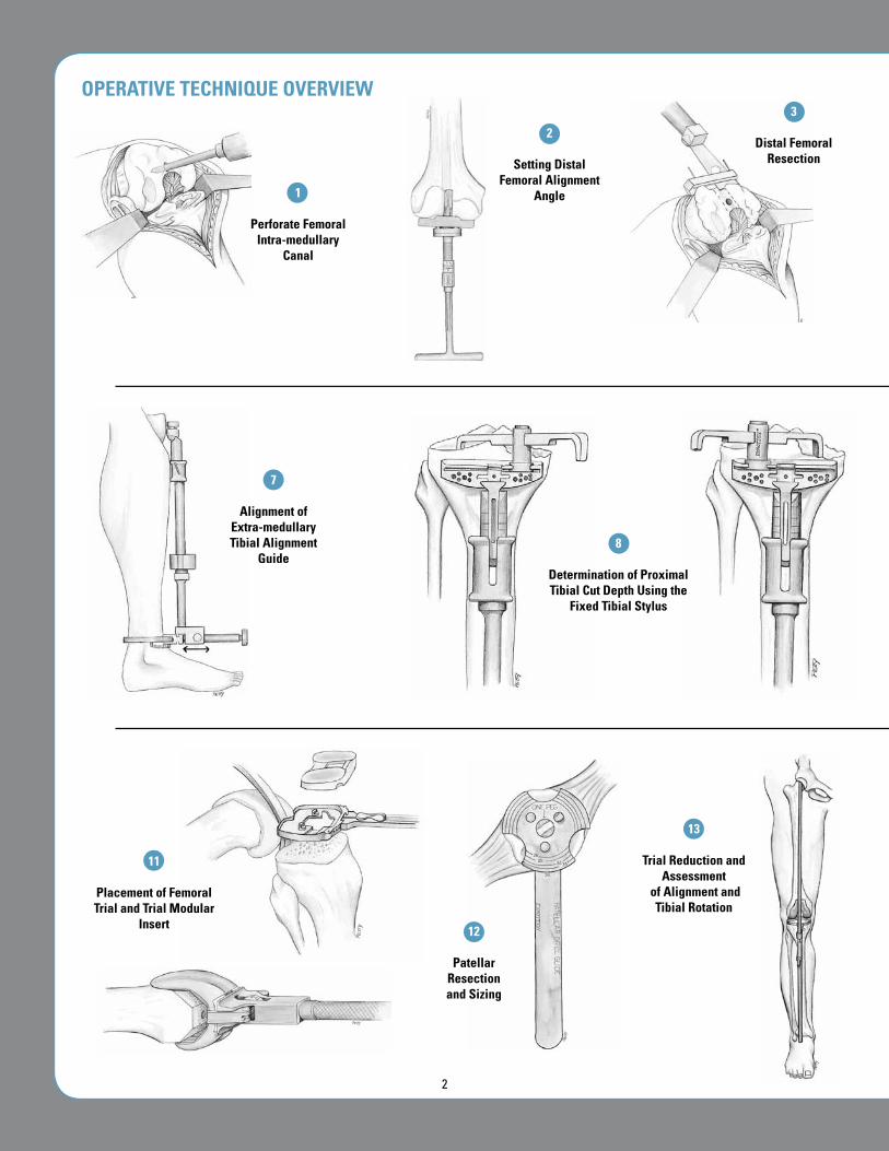
perforate Femoral Intra-medullary
Canal
2
Setting Distal Femoral Alignment
Angle
3
Distal Femoral Resection
13
Trial Reduction and Assessment
of Alignment and Tibial Rotation
12
patellar Resection and Sizing
11
placement of Femoral Trial and Trial Modular
Insert
7
Alignment of Extra-medullary Tibial Alignment
Guide 8
Determination of proximal Tibial Cut Depth using the
Fixed Tibial Stylus
OpERATIvE TEChNIquE OvERvIEw
2
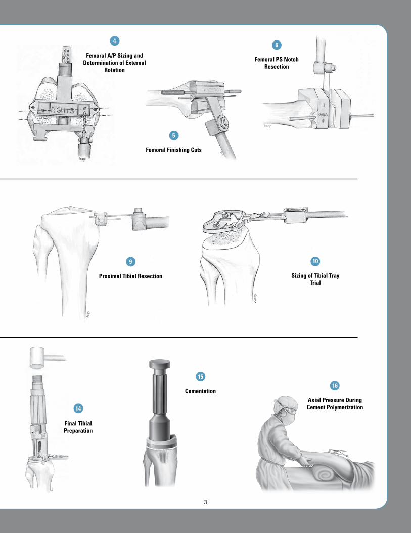
4
Femoral A/p Sizing and Determination of External
Rotation
5
Femoral Finishing Cuts
6
Femoral pS Notch Resection
9
proximal Tibial Resection
10
Sizing of Tibial Tray Trial
15
Cementation
14
Final Tibial preparation
16
Axial pressure During Cement polymerization
3

Figure 1Pre-Operative Full Limb Length Radiographs
Figure 2Skin Incisions
Figure 3Incision of the Medial Parapatellar Capsule
DETAILED OpERATIvE TEChNIquE
pRE-OpERATIvE pLANNING
Radiographs
High-quality radiographs are essential forprecise pre-operative planning. Films of thefull lengthofthelimbwillallowthesurgeontodetermine themechanicalandanatomicalaxisofthekneemoreaccurately(Figure 1).
Templating
Templating is done in both the anterior/posterior and lateral planes to estimateimplantsizeforboththefemurandtibia.
AppROACh AND ExpOSuRE
The surgeon may use either a straight ormedialparapatellarskinincision(Figure 2).
The joint is entered through a medialparapatellar incision in the capsule. Theincision should be extended proximally inthequadricepstendonanddistallyalongthemedial border of the patellar tendon to thetibialtubercle(Figure 3).
4
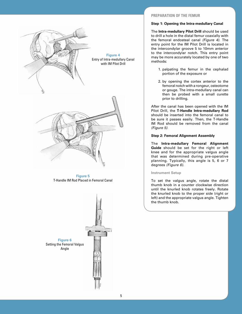
pREpARATION OF ThE FEMuR
Step 1: Opening the Intra-medullary Canal
TheIntra-medullary Pilot Drillshouldbeusedtodrillaholeinthedistalfemurcoaxiallywiththe femoral endosteal canal (Figure 4). Theentrypoint for the IMPilotDrill is located inthe intercondylargroove5 to10mmanteriorto the intercondylar notch. This entry pointmaybemoreaccuratelylocatedbyoneoftwomethods:
1.palpating the femur in the cephaladportionoftheexposureor
2.by opening the cortex anterior to thefemoralnotchwitharongeur,osteotomeorgouge.Theintra-medullarycanalcanthen be probed with a small curettepriortodrilling.
AfterthecanalhasbeenopenedwiththeIMPilot Drill, the T-Handle Intra-medullary Rod should be inserted into the femoral canal tobe sure it passes easily. Then, the T-HandleIM Rod should be removed from the canal(Figure 5).
Step 2: Femoral Alignment Assembly
The Intra-medullary Femoral Alignment Guide should be set for the right or leftknee and for the appropriate valgus anglethat was determined during pre-operativeplanning. Typically, this angle is 5, 6 or 7degrees(Figure 6).
Instrument Setup
To set the valgus angle, rotate the distalthumbknob inacounterclockwisedirectionuntil the knurled knob rotates freely. Rotatetheknurledknob to theproperside (rightorleft)andtheappropriatevalgusangle.Tightenthethumbknob.
Figure 5 T-Handle IM Rod Placed in Femoral Canal
Figure 6Setting the Femoral Valgus
Angle
Figure 4Entry of Intra-medullary Canal
with IM Pilot Drill
5

TheIM AlignmentGuideisassembledtotheT-HandleIMRodandtheT-HandleIMRodisintroducedintothefemoralcanal(Figure 7).The alignment assembly should be broughtinto contact with the subchondral plate onthe distal surface of both femoral condyles.Thefixtureisthenrotatedsothatitsposterioraspect is coplanar with a line drawn acrosstheposteriorcondylesofthefemur.Rotationshould be approximately correct, but is notcritical in this step (as it will be in Step5, page 7). The alignment assembly maybe pinned to the distal condyles if addedstabilityisdesired.
Step 3: Resection of Distal Femoral Bone
The Distal Femoral Resection Guide shouldbe placed on the assembly and securedto the femur with headless pins or 1/8-inch Drill Bits (Figure 8). (The ResectionGuidemayalsobeplacedonthealignmentassembly before the assembly is placed inthe femur.) The preferred position for thepinsisintheholesmarkedwitha“0”.Thispin position allows the Resection Guide toberelocatedinadistalorproximaldirectionin2mm increments, incaseamoreor lessaggressive femoral resection is needed. Inthe neutral (“0”) position, 10mm of distalboneisresected.Thestandard10mmdistalcutestablishedwiththisinstrumentsystemis 2mm greater than the thickness of thefemoralcomponent.
DistalfemoralboneshouldberesectedusinganoscillatingsawbladeplacedthroughthecuttingslotsoftheResectionGuide(Figure 9).A saw blade of the appropriate thickness(.050” or 1.27mm) is crucial to achievinga precise cut in the slotted blocks. If thesurgeon prefers to cut the distal femurwithout using a slot, the same ResectionGuidemaybeused.TheopencuttingsurfaceoftheResectionGuideis8mmdistaltothecutting slot. To establish the appropriatebone resection for cutting on the surfaceoftheResectionGuide,thesurgeonshouldmovetheResectionGuide8mmproximallyontheIMAlignmentGuidebeforepinning.
Figure 7 IM Alignment Guide
Assembly
Figure 8 Placement and Pinning of
the Resection Guide
Figure 9Distal Femoral Cut
6

To be sure that the resected surfaces of themedial and lateral femoral condyles are flatand coplanar, a flat Resection Guide maybe used to check the cuts. If necessary,refinementsofthecutmaybemade.
Recutting the Distal Femur
There are two pin holes in the ResectionGuidedistaltothecuttingslot.Iftheoriginalpins have been removed and holes cannotbe relocated, headed pins can be placed inthese holes to relocate the Resection Guide.With the headed pins hanging in the holes,thepinsshouldbeplacedagainsttheresecteddistalbonesurface.Thislocatestheslot2mmproximal to theoriginaldistal resection.TheResectionGuidemaythenberepinnedintheneutralpositionasbeforeandadditionalcutscanbemadeasnecessary.
Step 4: Sizing of Femoral Component
The Femoral A/P Sizer should be broughtflush against the resected surface of thedistal femur (Figure 10). The posterior feetshouldthenbepulledupagainsttheposteriorfemoral condyles. If a posterior condylardefect is present, the A/P Sizer should berotated toaposition thataccommodates thedefect.TheA/PSizershouldbeplacedinthemedial/lateral position as though it were acontinuationofthefemur.TheA/PSizermaybestabilizedwithpinsifthesurgeondesires.
Astylusshouldbeplacedbetweenthehighestand lowest points on the anterior femoralcortex (Figure 11). The A/P Sizer should bestabilizedbyhand.Femoralsizemaybereadfrom the color-coded scale. If the readingis between sizes, it is usually preferable tochoosethesmallersize.
Step 5: Establishment of Rotation of Femoral Component
Correctrotationofthefemoralcomponentisbestestablishedbyusingthetransepicondylaraxisasaguide (Figure 12).A 0- or 3-DegreeDrill Bushing should be selected for 0 or 3degreesofexternalrotation.TherightorleftDrill Bushing may then be inserted into theA/P Sizer. Two 0.156-inch (4mm) holes aredrilledandtheA/PSizeristhenremoved.Thefemurisnowreadyforanterior/posteriorandchamferboneresection.
Figure 10A/P Sizer Placement on Distal Femur
Figure 11Establishment of Anterior Limit of Femoral Size
Figure 12 Establish Proper Femoral
Component Rotation
7

Step 6: Resection of Anterior, Posterior and Chamfer Femoral Bone
The surgeon should secure the Femoral Finishing Guideofthepreviouslydeterminedsize to the distal surface of the femur bydriving the guide pins into the drilled holes(Figure 13). The Femoral Finishing Guidemaybefurthersecuredbyholdingitwiththeremovable handles or by placing outriggerpins.
The anterior and posterior femoral surfacesshouldberesectedwithan .050”or1.27mmsaw blade (Figures 14 and 15). The chamfercutsshouldthenbemade.Femoralpreparationis now complete for the posterior cruciateretainingprosthesis.Iftheposteriorstabilizedfemoral component has been selected, thebox cut for this component is described onpage9.
TheFemoral Trial isnowplaced (Figure 16).UseofaLocking Femoral Impactormayhelpavoid tipping of the prosthesis into flexion.Slight upward pressure on the Impactorhandle during impaction will prevent thecomponentfromrotatingintoflexion.
Note: Non-slotted Resection Guides are available for the anterior/posterior and chamfer cuts for the surgeon who prefers to use these.
Figure 13Placement of Femoral
Finishing Guide
Figure 14Anterior and Posterior Femoral Resection
Figure 15 Chamfer Bone Resection
Figure 16Placement of Femoral Trial
8
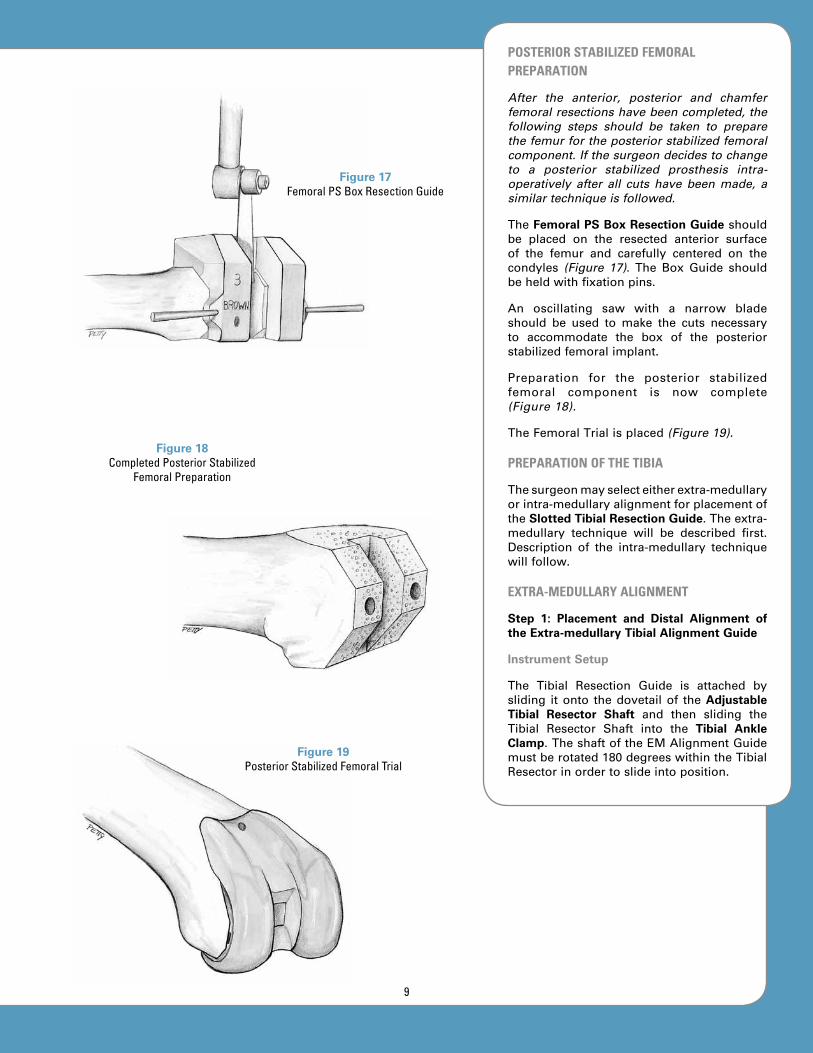
pOSTERIOR STABILIZED FEMORAL pREpARATION
After the anterior, posterior and chamfer femoral resections have been completed, the following steps should be taken to prepare the femur for the posterior stabilized femoral component. If the surgeon decides to change to a posterior stabilized prosthesis intra-operatively after all cuts have been made, a similar technique is followed.
TheFemoral PS Box Resection Guideshouldbe placed on the resected anterior surfaceof the femur and carefully centered on thecondyles (Figure 17). The Box Guide shouldbeheldwithfixationpins.
An oscillating saw with a narrow bladeshould be used to make the cuts necessaryto accommodate the box of the posteriorstabilizedfemoralimplant.
Preparation for the posterior stabilizedfemoral component is now complete(Figure 18).
TheFemoralTrialisplaced(Figure 19).
pREpARATION OF ThE TIBIA
Thesurgeonmayselecteitherextra-medullaryorintra-medullaryalignmentforplacementofthe Slotted Tibial Resection Guide.Theextra-medullary technique will be described first.Description of the intra-medullary techniquewillfollow.
ExTRA-MEDuLLARy ALIGNMENT
Step 1: Placement and Distal Alignment of the Extra-medullary Tibial Alignment Guide
Instrument Setup
The Tibial Resection Guide is attached bysliding itonto thedovetailof theAdjustable Tibial Resector Shaft and then sliding theTibial Resector Shaft into the Tibial Ankle Clamp.TheshaftoftheEMAlignmentGuidemustberotated180degreeswithintheTibialResectorinordertoslideintoposition.
Figure 17 Femoral PS Box Resection Guide
Figure 18Completed Posterior Stabilized
Femoral Preparation
Figure 19Posterior Stabilized Femoral Trial
9
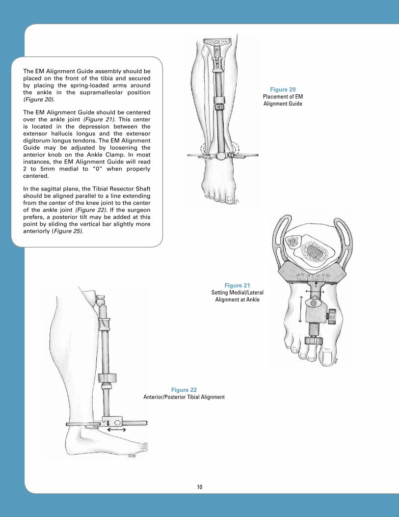
TheEMAlignmentGuideassemblyshouldbeplaced on the front of the tibia and securedby placing the spring-loaded arms aroundthe ankle in the supramalleolar position(Figure 20).
TheEMAlignmentGuideshouldbecenteredover the ankle joint (Figure 21). This centeris located in the depression between theextensor hallucis longus and the extensordigitorumlongustendons.TheEMAlignmentGuide may be adjusted by loosening theanterior knob on the Ankle Clamp. In mostinstances, theEMAlignmentGuidewill read2 to 5mm medial to “0” when properlycentered.
Inthesagittalplane,theTibialResectorShaftshouldbealignedparalleltoalineextendingfromthecenterofthekneejointtothecenterof the ankle joint (Figure 22). If the surgeonprefers,aposterior tiltmaybeaddedat thispointbyslidingtheverticalbarslightlymoreanteriorly(Figure 25).
Figure 20Placement of EM Alignment Guide
Figure 21Setting Medial/Lateral
Alignment at Ankle
Figure 22Anterior/Posterior Tibial Alignment
10

Step 2: Proximal Alignment
In the frontal plane, the Tibial ResectorShaft should be aligned with the long axisof the tibia (Figure 23). Normally, this maybe accomplished by centering the verticalExtra-medullary Alignment Rod on thecenterofthetibialplateau.
The EM Alignment Guide should be setrotationallybyaligningitwiththesecondtoeor, if there is an ankle or foot deformity, bypointingitinthesamedirectionthatthetibialtuberclepoints(Figure 24).
Theposteriorslopepresentintheindividualtibia should, in most cases, be reproducedin the proximal tibial resection. In mosttibia, this is a 3- to 5-degree angle. Thesurgeon may choose one of two methodsfor establishing the posterior slope of theproximaltibia.
Method 1: The Tibial Resector Shaft shouldbesetsothatit isparallelwiththelongaxisof the tibia in the anterior/posterior plane(Figure 25). The posterior slope may thenbe set by leaving the cam adjustment on“0” and adjusting the EM Alignment Rodmore anteriorly at the ankle. To make thisadjustment, loosen the thumb screw on thesideoftheAnkleClamp,setthealignmentinthe desired position and tighten the thumbscrew.
Method 2: The Tibial Resector Shaft shouldbeplacedparalleltothelongaxisofthetibia(Figure 26). The posterior slope should beset by dialing the selected degree of slopewiththecamadjustment.Thisslopeangleisnormally3to5degrees.
Step 3: Determination of Tibial Resection Depth
TheTibialResectionGuideshouldbeplacedonthedovetailoftheEMAlignmentGuideiftheguidewasnotpre-assembled.TheFixed Tibial Stylus shouldbeplaced in thecuttingslotoftheEMAlignmentGuidesothateitherthe side marked “most normal” or the sidemarked “most defective” extends over thetibialplateau.
Figure 23Proximal Alignment of EM
Alignment Guide in Frontal Plane
Figure 24Rotational Alignment
Figure 25 Method 1: Anterior/Posterior
Alignment by Angling EM Alignment Rod to Create
Posterior Tilt
Figure 26 Method 2: Anterior/Posterior Alignment Using Cam on EM
Alignment Guide
11
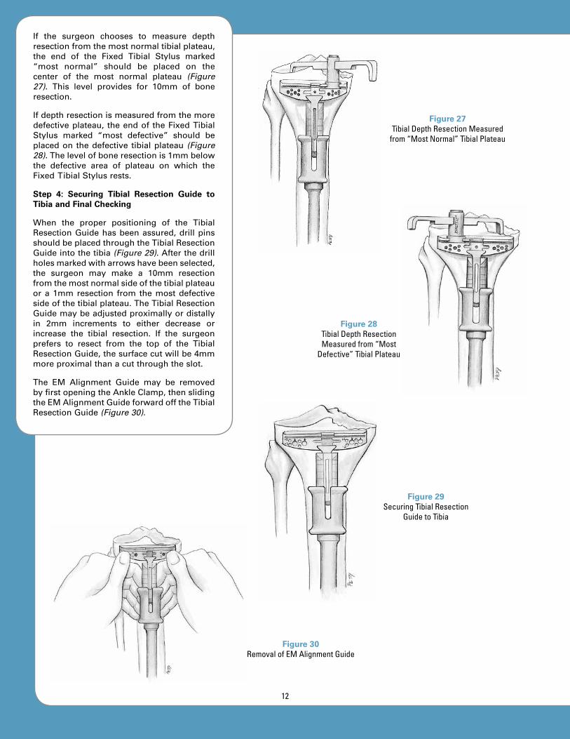
If the surgeon chooses to measure depthresectionfromthemostnormaltibialplateau,the end of the Fixed Tibial Stylus marked“most normal” should be placed on thecenter of the most normal plateau (Figure 27). This level provides for 10mm of boneresection.
Ifdepthresectionismeasuredfromthemoredefectiveplateau, theendof theFixedTibialStylus marked “most defective” should beplacedon thedefective tibialplateau (Figure 28).Thelevelofboneresectionis1mmbelowthe defective area of plateau on which theFixedTibialStylusrests.
Step 4: Securing Tibial Resection Guide to Tibia and Final Checking
When the proper positioning of the TibialResectionGuidehasbeenassured,drillpinsshouldbeplacedthroughtheTibialResectionGuideintothetibia(Figure 29).Afterthedrillholesmarkedwitharrowshavebeenselected,the surgeon may make a 10mm resectionfromthemostnormalsideofthetibialplateauora1mmresection from themostdefectivesideofthetibialplateau.TheTibialResectionGuidemaybeadjustedproximallyordistallyin 2mm increments to either decrease orincrease the tibial resection. If the surgeonprefers to resect from the top of the TibialResectionGuide,thesurfacecutwillbe4mmmoreproximalthanacutthroughtheslot.
The EM Alignment Guide may be removedbyfirstopeningtheAnkleClamp,thenslidingtheEMAlignmentGuideforwardofftheTibialResectionGuide(Figure 30).
Figure 27Tibial Depth Resection Measured
from “Most Normal” Tibial Plateau
Figure 28Tibial Depth Resection Measured from “Most
Defective” Tibial Plateau
Figure 29 Securing Tibial Resection
Guide to Tibia
Figure 30 Removal of EM Alignment Guide
12

The surgeon should make a final check forproper alignment by securing the Mauldin Multi-Tool to theTibialResectionGuideandplacinganEMAlignmentRodthroughoneoftheholesinthehandle(Figure 31).AlignmentcanalsobecheckedbyplacingtheT-HandleIM Rod over the drill points that securethe proximal Tibial Resection Guide. ThisT-Handle IM Rod may be allowed to danglefromthedrillpoints.AssumingtheT-HandleIMRodliesproximallyinthesagittalmidlineoftheproximaltibialplateau,thedistaltipofthebarshouldlieoverthecenteroftheanklejoint. The EM Alignment Rod in the handleshows alignment in both planes while theT-HandleIMRodshowsalignmentinonlythefrontalplane.
INTRA-MEDuLLARy ALIGNMENT
Step 1: Opening of the Intra-medullary Canal
The IM Pilot Drill is used to drill a hole inthe proximal tibia coaxially with the tibialendostealcanal(Figure 32).Theentrypointfor the IM Pilot Drill is most accuratelylocated by finding the proximal extensionof the center of the intra-medullary canalonthepre-operativeX-rayfilms.Thispointoften lies between the tibial spines in thefrontalplaneandjustanteriortotheminthesagittalplane.
The surgeon may use an awl, rongeur,osteotome or gouge to help open the entrypointfortheIMPilotDrill.Theintra-medullarycanalmaythenbeprobedwithasmallcurettepriortodrilling.ThecanalisthenenteredwiththeIMPilotDrill.
AfteropeningthecanalwiththeIMPilotDrill,the surgeon should insert the T-Handle IMRod into the tibialcanal tobesure itpasseseasily(Figure 33).ThentheT-HandleIMRodshouldberemovedfromthecanal.
Figure 31Final Alignment Check
Figure 32Locating Entry Point for
IM Pilot Drill
Figure 33T-Handle IM Rod in
Tibial Canal
13

Step 2: Assembly and Placement of IM Alignment Guide
Instrument Setup
Slide the Tibial Resection Guide onto theanterior dovetail of the IM Alignment Guideand tighten the anterior knurled knob.Rotate the superior knob clockwise until theresection head is in its highest position.Assure that the varus/valgus adjustment issetat“0”.Rotatetheslope-selectionknobtothe desired position. Loosen the rod-lockingknobandslide theT-Handle IMRod into theIMAlignmentGuide.
TheT-HandleIMRodshouldbeinsertedintothe IM Alignment Guide and again insertedinto the tibial intra-medullary canal (Figure 34).
Step 3: Guide Alignment and Stabilization
The IM Alignment Guide should be alignedrotationallybyaligningitwiththesecondtoeor, if there is a foot or ankle deformity, bypointing it in thesamedirectionas the tibialtuberclepoints.
After rotational alignment has been set, theflutes of the IM Alignment Guide shouldbe slightly tapped into the tibial plateau tostabilizetheIMAlignmentGuide(Figure 35).
To be sure that varus/valgus alignment iscorrect, the surgeon should place an EMAlignment Rod in the anterior hole of theIM Alignment Guide (Figure 36). The EMAlignment Rod should be aligned with thecenter of the ankle joint. This center lies inthedepressionbetweentheextensorhallucislongus and extensor digitorum longustendonsattheankle.
The posterior slope should be adjustedby dialing the appropriate degrees on theposterior slope adjustment knob (Figure 37). The EM Alignment Rod will show the slopecomparedwiththesagittalplaneoftheintra-medullarycanalofthetibia.
Step 4: Determination of Tibial Resection Depth
TheTibialResectionGuideshouldbeplacedonthedovetailof the IMAlignmentGuide iftheResectionGuidewasnotpre-assembled.The Fixed Tibial Stylus should be placed inthe cutting slot of the Resection Guide witheither the side marked “most normal” or“most defective” extending over the tibialplateau.Depthresectionshouldbesetusingthe adjustment knob near the top of the IMAlignmentGuide.
Figure 34Placement of IM Alignment Guide into Tibia
Figure 35Stabilization of IM Alignment Guide
Figure 36 Varus/Valgus Alignment
14

Figure 37Posterior Slope Adjustment
If the surgeon chooses to measure depthresectionfromthemostnormaltibialplateau,the “most normal” end of the Fixed TibialStylusshouldbeplacedonthecenterof themostnormalplateau.This levelprovides for10mmofboneresection.
Note: See page 12, Figure 27.
Ifdepthresectionismeasuredfromthemoredefectiveplateau,thesideoftheFixedTibialStylus marked “most defective” should beplaced on the defective tibial plateau. Thelevel of bone resection is 1mm below thedefectiveareaofplateauonwhich theFixedTibialStylusrests.
Note: See page 12, Figure 28.
Step 5: Pinning of Tibial Resection Guide, Removal of IM Alignment Guide and Final Checking
When the proper positioning of the TibialResectionGuidehasbeenassured,drillpinsareplacedthroughtheTibialResectionGuideintothetibiathroughtheholesmarkedwithanarrow(Figure 38).Afterthedrillholesmarkedwith arrows have been selected, 10mmresection may be accomplished from theendof theFixedTibialStylusmarked“mostnormal” or 1mm from the end of the FixedTibial Stylus marked “most defective”. TheamountoftibiaresectedmaybedecreasedorincreasedbyproximalordistaladjustmentoftheTibialResectionGuidein2mmincrements.
If the surgeon prefers to resect from the top of the guide, the surface cut will be 4mm more proximal than a cut through the slot.
ToremovetheIMAlignmentGuide,theknobwhichholdstheguideontheT-HandleIMRodshouldbeloosenedandtheT-HandleIMRodshouldberemoved.TheIMAlignmentGuideand T-Handle IM Rod should be removedtogether as the end of the T-Handle IM Rodis loosened in the intra-medullary canal.An extractor hook and slap hammer areavailabletoaidinremovingtheT-HandleIMRod and IM Alignment Guide if necessary.Alternatively, both the T-Handle IM RodandtheIMAlignmentGuidemaybetappedlightlywithamallettoremove.
Figure 38 Fixation of Tibial Resection
Guide to Tibia
15

Afinalcheck forproperalignmentshouldbeperformedbysecuringtheMauldinMulti-Toolto the Tibial Resection Guide and placing anEMAlignmentRod throughoneof theholesinthehandle(Figure 39).Alignmentmayalsobe checked by placing the T-Handle IM Rodover thedrillpoints thatsecure theproximalTibialResectionGuide.ThisT-HandleIMRodmaybeallowedtodanglefromthedrillpointsand, assuming that the T-Handle IM Rodlies proximally in the sagittal midline of theproximaltibialplateau,thedistaltipofthebarshouldlieoverthecenteroftheanklejoint.
The EM Alignment Rod in the handle shows alignment in both planes while the T-Handle IM Rod shows alignment in only the frontal plane.
Step 6: Proximal Tibial Bone Resection
Bone resection should be performed bycuttingthroughtheslotoftheTibialResectionGuide with an oscillating saw (Figure 40).(If the surgeon chooses to cut on the uppersurface of the Tibial Resection Guide, 4mmlessbonewillberesectedsotheappropriateadjustment should be made). The surgeonshouldtakecareduringthetibialresectiontoavoid injury to the collateral structures andthe posterior neural and vascular structures.Thetibialattachmentoftheposteriorcruciateligament should be saved when cruciateretainingprosthesesaretobeused.
The cut tibial surface should be sized usingtheTibial Tray Trials (Figure 41).Foragivensize of femoral component, the surgeon hasachoiceofthreeTibialTrayTrialsizes:theseincludethesamenominalsizeasthefemoralcomponent, one size larger and one sizesmaller. This system provides for a tibialarticularsurfacethatisprecision-matchedforits mating femoral component; this resultsin the low articular stresses seen with theOptetrak prosthesis. The Tibial Tray Trialshave a color code that matches the femoraltrial component.ThesurgeonshouldchoosethelargestTibialTrayTrialthatfitswithinthebordersoftheresectedtibialsurface,withoutanyoverhang.
Figure 39Final Alignment Check
Figure 40Final Alignment Check
Figure 41Sizing of Tibial Tray Trial
16

pLACEMENT AND SIZING OF TRIAL COMpONENTS
TheFemoralTrial isplacedwith theLockingFemoral Impactor or by hand (Figure 42). If placed by hand, it is helpful to pullproximally on the component with a bonehookintheintercondylarnotchtoassurethecomponent goes straight on the preparedbone surfaces, avoiding the tendency thatfemoral components sometimes exhibit ofrotating slightly into flexion. Ensure that thecomponent is centered on the condyles inthe medial/lateral direction. When correctpositioning is assured, the component isfullyseatedwiththeFemoralImpactorandamallet.
The size, number and color of the Modular Tibial Insert Trial matches that of the size,number and color dot on the Femoral Trial(Figure 43). The surgeon should assess thedifferent thicknesses of Tibial Insert Trials,usuallybeginningwiththe9mmTibial InsertTrial. The correct selection is the insert thatallows for full extension and slight laxity(similar to that of a typical normal knee) inboth extension and flexion. The range ofmotionmaybecheckedatthisstage,butthefinal check for kinematics is best completedafterpatellarpreparation.
pREpARATION OF ThE pATELLA
Step 1: Resection of the Patellar Articular Surface
The articular surface of the patella may beresectedwithorwithouttheuseoftheSlotted Patellar Resection Guide, depending on thesurgeon’spreference.Resectionmaybedonewiththekneeeitherflexedorextended.
Method 1: Free-Hand Resection
ForpatellarresectionperformedwithoutthePatellar Resection Guide (“free hand”), thepatella should be stabilized with large towelclipsorsimilarinstruments(Figure 44).Eitheroftwolandmarksshouldbeused:
1.fromedgeofmedialarticularsurfacetoedgeoflateralarticularsurfaceor
2.beginningjustposteriortothepatellartendon origin at the inferior pole ofthe patella and cutting superiorly,paralleltotheplaneofthepatella.Theposterior patellar surface should beresectedwithanoscillatingsaw.
Figure 42Placement of Femoral Trial
Figure 43 Selection of Proper Tibial Insert Trial
Figure 44Free-Hand Resection
of Patella
17
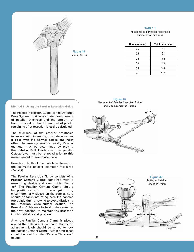
Method 2: Using the Patellar Resection Guide
ThePatellarResectionGuidefortheOptetrakKneeSystemprovidesaccuratemeasurementof patellar thickness and the amount ofbone resected so that the amount of patellaremainingafterresectioniseasilycalculated.
The thickness of the patellar prosthesisincreases with increasing diameter—just asit does with the normal patella and mostother totalkneesystems (Figure 45).Patellardiameter may be determined by placingthe Patellar Drill Guide over the patella.Osteophytes must be removed prior to thismeasurementtoassureaccuracy.
Resection depth of the patella is based onthe estimated patellar diameter measured(Table 1).
The Patellar Resection Guide consists of aPatellar Cement Clamp combined with ameasuring device and saw guide (Figure 46). The Patellar Cement Clamp shouldbe positioned with the saw guide ringcircumferentially placed on the patella. Careshould be taken not to squeeze the handlestootightlyduringsawingtoavoiddisplacingthe Resection Guide surface location. TheResectionGuidemaybeheldinthecenter(atthepivotposition) tomaintain theResectionGuide’sstabilityandposition.
After the Patellar Cement Clamp is placedaround the patella and tightened, the clampadjustment knob should be turned to lockthePatellarCementClamp.Patellarthicknessshouldbereadfromthe“PatellarThickness”gauge.
Figure 45Patellar Sizing
TABLE 1Relationship of Patellar Prosthesis
Diameter to Thickness
Diameter (mm) Thickness (mm)
26 5.1
29 6.1
32 7.2
35 8.5
38 10.0
41 11.1
Figure 46Placement of Patellar Resection Guide
and Measurement of Patella
Re
se
ct
ion
A
mo
un
t
PAtellAR thickness
Figure 47 Setting of Patellar Resection Depth
18

The “wing-nut” knob for resection depthadjustment should be turned to the desiredresection depth (Figure 47). If the surgeonprefers to resect the amount of bone whichwillbereplacedbyaspecificdiameterpatellarcomponent,thethicknessesarelistedinTable1. After the resection depth is selected, thepatellaisreadyforresection.
Thepatellar surfaceshouldbe resectedwithanoscillatingsaw(Figure 48).Thesawbladeshould be placed through the cutting slot ofthesawguideringforresection.
Step 2: Final Sizing and Drilling of Patella
When patellar resection is complete, finaldetermination of size and hole preparationshould be performed using the Patellar DrillGuide (Figure 49). The Drill Guide shouldbe placed on the resected patellar surface,providing a size check for all sizes of thepatella. It also provides guide holes for thedrillforthree-pegorsingle-pegprostheses.
Holes should be drilled through the PatellarDrillGuide ineither the three-holeorsingle-holeconfiguration(Figures 50 and 51).
Step 3: Patellar Trial Placement
TheappropriatesizeoftheThree-Peg Patella Trialshouldbeplacedonthepatella.
Figure 48Patellar Resection
Figure 49Placement of Patellar
Drill Guide and Final Size Check
Figure 50Three Peg Holes Figure 51
Single Hole
19

FINAL pROSThESIS TRIAL ChECk
Final prosthesis trial check should includeassessmentof:
ALIGNMENT,STABILITY,MOTIONandPATELLARTRACKING
Alignment Check
With the knee in full extension and theMauldin Multi-Tool assembled to the TibialBase Plate, EM Alignment Rods should beplaced in the holes in the Mauldin Multi-Tool and the alignment should be assessed(Figure 52). Proper rotation of the tibialcomponent should be determined by itscongruency with the femoral component.Normally, the anterior plane of the tibialcomponent will point approximately in thedirection of the tibial tubercle and secondtoe when congruency is established. Whenproperalignment isachieved, theAlignmentRods will be centered over the ankle andestimatedlocationofthecenterofrotationofthefemoralhead.
Stability Check
The knee should be assessed for stability inboth extension and flexion (Figures 53 and 54).Theextensioncheckshouldbeperformedwiththekneeflexedafewdegreestorelaxtheposterior capsule.However, thekneeshouldextend fully. The flexion check should beperformedwiththekneeflexedto90degrees.The most appropriate stability is achievedwhenthemedialandlateralopeningissimilarto that of a normal knee during applicationofvalgusandvarusstress.Anadjustmentofligament balance may be needed, if there isdifferentialligamenttightnessbetweenvarusandvalgusinflexionorextension.
Figure 52Assessment of Alignment
Figure 53 Stability Check in
Extension
Figure 54Stability Check in Flexion
20
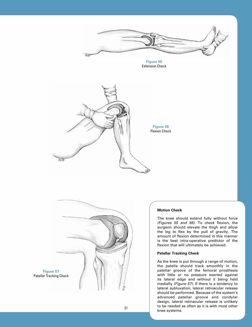
Motion Check
The knee should extend fully without force(Figures 55 and 56). To check flexion, thesurgeon should elevate the thigh and allowthe leg to flex by the pull of gravity. Theamountofflexiondeterminedinthismanneris the best intra-operative predictor of theflexionthatwillultimatelybeachieved.
Patellar Tracking Check
Asthekneeisputthrougharangeofmotion,the patella should track smoothly in thepatellar groove of the femoral prosthesiswith little or no pressure exerted againstits lateral edge and without it being heldmedially (Figure 57).Ifthereisatendencytolateralsubluxation, lateralretinacularreleaseshouldbeperformed.Becauseofthesystem’sadvanced patellar groove and condylardesign, lateral retinacular release is unlikelytobeneededasoftenasitiswithmostotherkneesystems.
Figure 55Extension Check
Figure 56Flexion Check
Figure 57Patellar Tracking Check
21

FINAL BONE pREpARATION: FEMuR
Femoral Peg Hole Preparation
Whenallchecksarecompleted,holesmaybe drilled for the pegs of the cruciate-retaining femoral component (Figure 58).If the surgeon prefers a tighter fit for thepegs and less cement intrusion into theholes,asmallpunchmaybeusedtocreatetheseholes.Alternatively,ifthesmallholescreatedfortheFemoralFinishingGuidearein the correct medial/lateral location, theymay be used for the pegs of the cruciateretaining femoral prosthesis. (This step isnot necessary for the posterior stabilizedfemoralcomponent.)
FINAL BONE pREpARATION: TIBIA
Step 1: Fixation of Tibial Tray Trial
Whenallcheckshavebeencompleted,pinsmaybedrilledordrivenintothemedialandlateral outrigger holes on the Tibial TrayTrial (Figure 59). Sometimes it is difficult toplace the lateralpin inpatientswitha largeor tight patellar tendon until the knee isflexedand theFemoralTrialprosthesisandTibial InsertTrial are removed. If this is thecase, the surgeon should place the medialpin, hold the proper rotation of the TibialTrayTrialwhiletheseothertrialcomponentsareremoved,andthenplacethe lateralpin.OncetheTibialTrayTrialinsertisremoved,the surgeon will have access to additionalpinfixationholesinthebottomoftheTibialTray Trial, should these be needed. At thispoint,thePatellarTrialprosthesisshouldberemoved.
Step 2: Drilling the Central Cavity
The Tibial Pilot Drill Guide should beassembledtotheTibialTrayTrialandtheIMPilotDrillshouldbedrilledtothedepththatmatchestheTibialTrayTrialsize(Figure 60).
Step 3: Tamping for Tibial Stem
Whether the Net-shape Tibial Finned Tampor Trapezoid Tibial Tamp is used, the sametechnique for preparation is followed. Thedifferent shapesarecreatedbyselecting theappropriateshapeofTamp.
Figure 58Peg Hole Preparation for Cruciate Retaining Femoral Component
Figure 59Fixation of Tibial Base
Plate Trial
Figure 60Drilling Central Cavity
22

TheselectedTampisassembledtotheTibial Tamp Guide by dialing REL (release) on thetray-size adjustment knob (Figure 61). Then,the Tamp is inserted into the Tamp Guide.After assembly, the Tamp Guide should besetfortheTibialTrayTrialsizebeingusedbydialingthepropernumberontheTibialTrayTrialsizeadjustmentknob.Thisaccomplishesthreethings:
1.securestheTamptotheTampGuide;
2.assures proper bone penetration fortheTamp;and
3.setstheTampGuidesothatitwillseatproperlyontheTibialBasePlateTrial.Ifthecorrectsizeisnotsetforthetraybeing used, the Tamp Guide will notseat properly on the Tibial Tray Trial.This is a safety check to be certaintamping is correct for the selectedTibialTrayTrial.
The Tamp Guide should be seated on theTibial Tray Trial and the Tamp driven intothetibiauntilthestopisreached(Figure 62).The appropriate size is marked by a line atthetopoftheTampGuide;thisservesasanadditionalchecktoindicatewhentheTampisfullyseated.
The Tamp should be removed by insertingthe small stud on the end of the MauldinMulti-Tool into thehole in thehandleof theTibialTamp,thenrotatingtheMauldinMulti-Tool to loosen the Tibial Tamp (Figure 63).If needed, a threaded hole is available forattachmentofaslaphammer to remove theTamp.However, it isusuallyeasily removedafter loosening with the Mauldin Multi-Tool.TheTampandTampGuidemayberemoved.Atthispoint,thefixationpinsandTibialBasePlate Trial should be removed. Next, theprostheseswillbeimplanted.
Figure 61Tibial Tamp Assembly and Setting of
Tamp for Selected Tray Size
Figure 62Tamping Tibia for
Tibial Stem
Figure 63Removal of Tibial Tamp
23
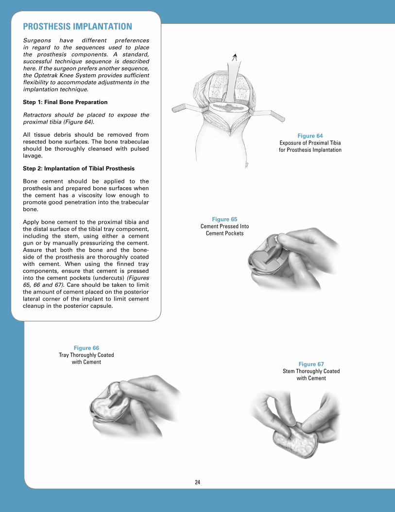
Figure 64Exposure of Proximal Tibia for Prosthesis Implantation
pROSThESIS IMpLANTATIONSurgeons have different preferences in regard to the sequences used to place the prosthesis components. A standard, successful technique sequence is described here. If the surgeon prefers another sequence, the Optetrak Knee System provides sufficient flexibility to accommodate adjustments in the implantation technique.
Step 1: Final Bone Preparation
Retractors should be placed to expose the proximal tibia (Figure 64).
All tissue debris should be removed fromresectedbonesurfaces.Thebonetrabeculaeshould be thoroughly cleansed with pulsedlavage.
Step 2: Implantation of Tibial Prosthesis
Bone cement should be applied to theprosthesisandpreparedbonesurfaceswhenthe cement has a viscosity low enough topromotegoodpenetrationintothetrabecularbone.
Applybonecementtotheproximaltibiaandthedistalsurfaceofthetibialtraycomponent,including the stem, using either a cementgunorbymanuallypressurizingthecement.Assure that both the bone and the bone-sideof theprosthesis are thoroughly coatedwith cement. When using the finned traycomponents, ensure that cement is pressedinto thecementpockets (undercuts) (Figures 65, 66 and 67).Careshouldbetakento limittheamountofcementplacedontheposteriorlateral corner of the implant to limit cementcleanupintheposteriorcapsule.
Figure 66Tray Thoroughly Coated
with Cement Figure 67Stem Thoroughly Coated
with Cement
Figure 65Cement Pressed Into
Cement Pockets
24

Figure 68Placement of Tibial
Prosthesis
Figure 69Installation of
Polyethylene Insert
Figure 70Insertion of Pre-Assembled
or All-Polyethylene Tibial Component
Introduce the tibial traycomponentonto theprepared tibial surface using the Locking Tibial Tray Impactor, applying a constantdownward force (Figure 68). Alternately, thepolyethyleneinsertmaybeassembledtothetibial tray prior to implantation. In this case,the Tibial Insert Impactor should be used toinsertthepre-assembledcomponents(Figure 69).Amalletcanbeusedforfinalimpactionofthe tibial component. All extraneous cementmust be removed from the borders of thetibial component, starting posteriorly andworking around to the sides and front. Allcementmustberemovedfromtheposteriorcapsularareaoftheknee.
A Tibial Insert Trial should be used whenpressurizingthecementduringpolymerizationunless the polyethylene insert was pre-assembled to the tray before implantation.It is recommended to install the final insertimplant after the cement has polymerized.The all-polyethylene or metal-backed tibialcomponentmaybeusedinsteadofamodularcomponent, in which case the implantationtechnique is similar to the pre-assembledmodulartibialcomponent(Figure 70).
25
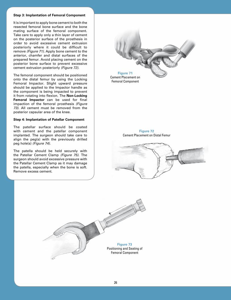
Step 3: Implantation of Femoral Component
Itisimportanttoapplybonecementtoboththeresected femoralbonesurfaceand thebonemating surface of the femoral component.Takecaretoapplyonlyathinlayerofcementon the posterior surface of the prosthesis inorder to avoid excessive cement extrusionposteriorly where it could be difficult toremove(Figure 71).Applybonecementtotheanterior, chamfer and distal surfaces of thepreparedfemur.Avoidplacingcementontheposterior bone surface to prevent excessivecementextrusionposteriorly(Figure 72).
Thefemoralcomponentshouldbepositionedonto the distal femur by using the LockingFemoral Impactor. Slight upward pressureshouldbeapplied to the Impactorhandleasthecomponent isbeing impacted topreventitfromrotatingintoflexion.TheNon-Locking Femoral Impactor can be used for finalimpaction of the femoral prosthesis (Figure 73). All cement must be removed from theposteriorcapsularareaoftheknee.
Step 4: Implantation of Patellar Component
The patellar surface should be coatedwith cement and the patellar componentimplanted. The surgeon should take care toalign the peg(s) with the previously drilledpeghole(s)(Figure 74).
The patella should be held securely withthe Patellar Cement Clamp (Figure 75). ThesurgeonshouldavoidexcessivepressurewiththePatellarCementClampasitmaydamagethepatella,especiallywhenthebone issoft.Removeexcesscement.
Figure 73Positioning and Seating of
Femoral Component
Figure 71Cement Placement on Femoral Component
Figure 72Cement Placement on Distal Femur
26
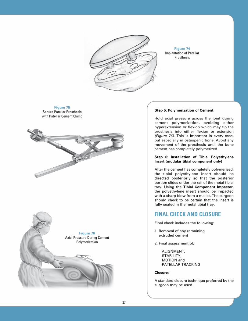
Step 5: Polymerization of Cement
Hold axial pressure across the joint duringcement polymerization, avoiding eitherhyperextensionor flexionwhichmay tip theprosthesis into either flexion or extension(Figure 76). This is important in every case,butespeciallyinosteopenicbone.Avoidanymovement of the prosthesis until the bonecementhascompletelypolymerized.
Step 6: Installation of Tibial Polyethylene Insert (modular tibial component only)
Afterthecementhascompletelypolymerized,the tibial polyethylene insert should bedirected posteriorly so that the posteriorportionslidesundertherailofthemetaltibialtray. Using the Tibial Component Impactor,the polyethylene insert should be impactedwithasharpblowfromamallet.Thesurgeonshould check to be certain that the insert isfullyseatedinthemetaltibialtray.
FINAL CHECK AND CLOSUREFinalcheckincludesthefollowing:
1.Removalofanyremainingextrudedcement
2.Finalassessmentof:
ALIGNMENT,STABILITY,MOTIONandPATELLARTRACKING
Closure:
Astandardclosuretechniquepreferredbythesurgeonmaybeused.
Figure 74Implantation of Patellar
Prosthesis
Figure 75Secure Patellar Prosthesis with Patellar Cement Clamp
Figure 76Axial Pressure During Cement
Polymerization
27

201-40-00 Intra-medullary Pilot Drill, Hudson
201-41-00 T-Handle Intra-medullary Rod
201-42-00 Intra-medullary Femoral Alignment Guide
201-43-00 Distal Femoral Resection Guide
201-44-00 Mauldin Multi-Tool
201-45-00 1/8” Drill Bit
201-47-00 Femoral A/P Sizer, Size 1-6201-47-10 Femoral A/P Sizer, Size 0-6†
201-48-00 Drill Bushing, 0 degrees
201-49-01 Drill Bushing, 3 degrees
201-50-00 A/P Sizer Collar Drill, 4mm
INSTRuMENT LISTINGCatalog Number part Description
† Special order
28
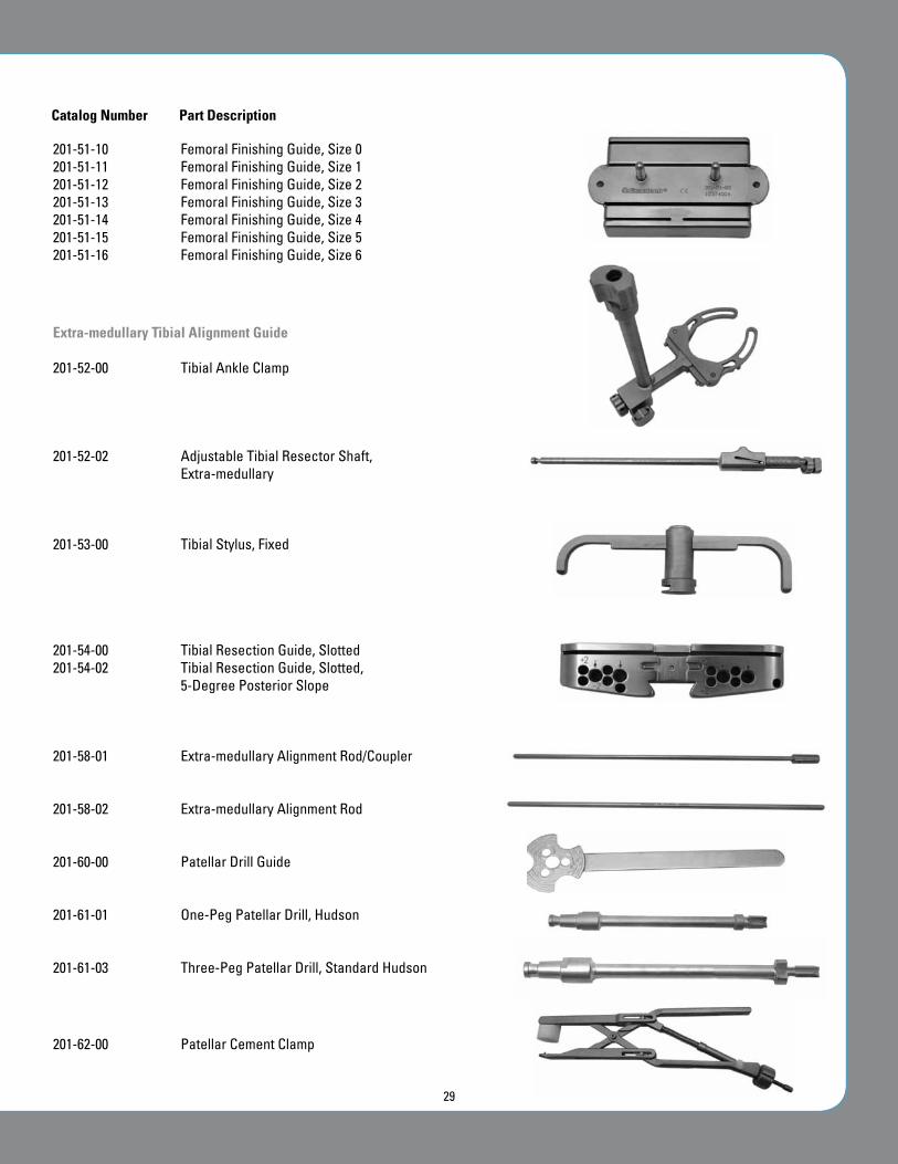
201-51-10 Femoral Finishing Guide, Size 0201-51-11 Femoral Finishing Guide, Size 1201-51-12 Femoral Finishing Guide, Size 2201-51-13 Femoral Finishing Guide, Size 3201-51-14 Femoral Finishing Guide, Size 4 201-51-15 Femoral Finishing Guide, Size 5201-51-16 Femoral Finishing Guide, Size 6
Extra-medullary Tibial Alignment Guide
201-52-00 Tibial Ankle Clamp
201-52-02 Adjustable Tibial Resector Shaft, Extra-medullary
201-53-00 Tibial Stylus, Fixed
201-54-00 Tibial Resection Guide, Slotted201-54-02 Tibial Resection Guide, Slotted,
5-Degree Posterior Slope
201-58-01 Extra-medullary Alignment Rod/Coupler
201-58-02 Extra-medullary Alignment Rod
201-60-00 Patellar Drill Guide
201-61-01 One-Peg Patellar Drill, Hudson
201-61-03 Three-Peg Patellar Drill, Standard Hudson
201-62-00 Patellar Cement Clamp
Catalog Number part Description
29

201-62-02 Slotted Patellar Resection Guide, Bishop
201-64-00 Femoral Impactor, Non-Locking
213-64-01 Locking Femoral Impactor
201-65-00 Locking Tibial Tray Impactor, Size 1-6201-65-10 Locking Tibial Tray Impactor, Size 0-6
201-69-01 Pin Puller
201-71-00 Tibial Pilot Drill Guide
201-72-00 Tibial Tamp, Finned, Net-Shape, Size 1-6201-72-10 Tibial Tamp, Finned, Net-Shape, Size 0-6
201-73-00 Tibial Tamp, Trapezoid
INSTRuMENT LISTINGCatalog Number part Description
30

201-74-00 Tibial Tamp Guide, Size 1-6201-74-10 Tibial Tamp Guide, Size 0-6
201-85-00 Resection Guide Handles
201-89-00 Intra-medullary Tibial Alignment Guide, Adjustable
201-90-00 Tibial Component Impactor
201-90-01 Tibial Insert Impactor
205-53-01 LPI Femoral Box Resection Guide, PS, Size 1205-53-02 LPI Femoral Box Resection Guide, PS, Size 2205-53-03 LPI Femoral Box Resection Guide, PS, Size 3205-53-04 LPI Femoral Box Resection Guide, PS, Size 4205-53-05 LPI Femoral Box Resection Guide, PS, Size 5
213-53-00 LPI Beta PS Notch Guide, Size O†
213-53-01 LPI Beta PS Notch Guide, Size 1213-53-02 LPI Beta PS Notch Guide, Size 2213-53-03 LPI Beta PS Notch Guide, Size 3213-53-04 LPI Beta PS Notch Guide, Size 4213-53-05 LPI Beta PS Notch Guide, Size 5213-53-06 LPI Beta PS Notch Guide, Size 6†
213-77-00 Cut Line Predictor
* Asymmetric CR and PS Femoral Trials also available † Special order
Catalog Number part Description
31

201-01-00 Femoral Trial, CR, Size 0*†
201-01-01 Femoral Trial, CR, Size 1*201-01-02 Femoral Trial, CR, Size 2*201-01-03 Femoral Trial, CR, Size 3*201-01-04 Femoral Trial, CR, Size 4*201-01-05 Femoral Trial, CR, Size 5*201-01-06 Femoral Trial, CR, Size 6*†
205-01-10 Femoral Trial, PS, Size 0*†
205-01-11 Femoral Trial, PS, Size 1*205-01-12 Femoral Trial, PS, Size 2*205-01-13 Femoral Trial, PS, Size 3*205-01-14 Femoral Trial, PS, Size 4*205-01-15 Femoral Trial, PS, Size 5*205-01-16 Femoral Trial, PS, Size 6*†
201-02-26 Three-Peg Patella Trial, Size 26201-02-29 Three-Peg Patella Trial, Size 29201-02-32 Three-Peg Patella Trial, Size 32201-02-35 Three-Peg Patella Trial, Size 35201-02-38 Three-Peg Patella Trial, Size 38201-02-41 Three-Peg Patella Trial, Size 41
201-80-09 Tibial Trial, Modular Insert, Size 0, 9mm†
201-80-11 Tibial Trial, Modular Insert, Size 0, 11mm†
201-80-13 Tibial Trial, Modular Insert, Size 0, 13mm†
201-80-15 Tibial Trial, Modular Insert, Size 0, 15mm†
201-80-18 Tibial Trial, Modular Insert, Size 0, 18mm†
201-81-09 Tibial Trial, Modular Insert, Size 1 Delta, 9mm201-81-11 Tibial Trial, Modular Insert, Size 1 Delta, 11mm201-81-13 Tibial Trial, Modular Insert, Size 1 Delta, 13mm201-81-15 Tibial Trial, Modular Insert, Size 1 Delta, 15mm201-81-18 Tibial Trial, Modular Insert, Size 1 Delta, 18mm201-81-22 Tibial Trial, Modular Insert, Size 1 Delta, 22mm201-81-26 Tibial Trial, Modular Insert, Size 1 Delta, 26mm201-81-30 Tibial Trial, Modular Insert, Size 1 Delta, 30mm
201-21-09 Tibial Trial, Modular Insert, Size 1, 9mm201-21-11 Tibial Trial, Modular Insert, Size 1, 11mm201-21-13 Tibial Trial, Modular Insert, Size 1, 13mm201-21-15 Tibial Trial, Modular Insert Size 1, 15mm201-21-18 Tibial Trial, Modular Insert, Size 1, 18mm201-21-22 Tibial Trial, Modular Insert, Size 1, 22mm†
201-21-26 Tibial Trial, Modular Insert, Size 1, 26mm†
201-21-30 Tibial Trial, Modular Insert, Size 1, 30mm†
201-22-09 Tibial Trial, Modular Insert, Size 2, 9mm201-22-11 Tibial Trial, Modular Insert, Size 2, 11mm201-22-13 Tibial Trial, Modular Insert, Size 2, 13mm
INSTRuMENT LISTINGCatalog Number part Description
* Asymmetric CR and PS Femoral Trials also available † Special order
32

201-22-15 Tibial Trial, Modular Insert, Size 2, 15mm201-22-18 Tibial Trial, Modular Insert, Size 2, 18mm201-22-22 Tibial Trial, Modular Insert, Size 2, 22mm†
201-22-26 Tibial Trial, Modular Insert, Size 2, 26mm†
201-22-30 Tibial Trial, Modular Insert, Size 2, 30mm†
201-23-09 Tibial Trial, Modular Insert, Size 3, 9mm 201-23-11 Tibial Trial, Modular Insert, Size 3, 11mm201-23-13 Tibial Trial, Modular Insert, Size 3, 13mm201-23-15 Tibial Trial, Modular Insert, Size 3, 15mm201-23-18 Tibial Trial, Modular Insert, Size 3, 18mm201-23-22 Tibial Trial, Modular Insert, Size 3, 22mm†
201-23-26 Tibial Trial, Modular Insert, Size 3, 26mm†
201-23-30 Tibial Trial, Modular Insert, Size 3, 30mm†
201-24-09 Tibial Trial, Modular Insert, Size 4, 9mm201-24-11 Tibial Trial, Modular Insert, Size 4, 11mm201-24-13 Tibial Trial, Modular Insert, Size 4, 13mm201-24-15 Tibial Trial, Modular Insert, Size 4, 15mm201-24-18 Tibial Trial, Modular Insert, Size 4, 18mm201-24-22 Tibial Trial, Modular Insert, Size 4, 22mm†
201-24-26 Tibial Trial, Modular Insert, Size 4, 26mm†
201-24-30 Tibial Trial, Modular Insert, Size 4, 30mm†
201-25-09 Tibial Trial, Modular Insert, Size 5, 9mm201-25-11 Tibial Trial, Modular Insert, Size 5, 11mm201-25-13 Tibial Trial, Modular Insert, Size 5, 13mm201-25-15 Tibial Trial, Modular Insert, Size 5, 15mm201-25-18 Tibial Trial, Modular Insert, Size 5, 18mm201-25-22 Tibial Trial, Modular Insert, Size 5, 22mm†
201-25-26 Tibial Trial, Modular Insert, Size 5, 26mm†
201-25-30 Tibial Trial, Modular Insert, Size 5, 30mm†
201-26-11 Tibial Trial, Modular Insert, Size 6, 11mm†
201-26-13 Tibial Trial, Modular Insert, Size 6, 13mm†
201-26-15 Tibial Trial, Modular Insert, Size 6, 15mm†
201-26-18 Tibial Trial, Modular Insert, Size 6, 18mm†
201-26-22 Tibial Trial, Modular Insert, Size 6, 22mm†
201-26-26 Tibial Trial, Modular Insert, Size 6, 26mm†
201-26-30 Tibial Trial, Modular Insert, Size 6, 30mm†
213-70-00 LPI Tibial Tray Trial, Size 0† 213-70-10 LPI Tibial Tray Trial, Size 1213-70-20 LPI Tibial Tray Trial, Size 2213-70-30 LPI Tibial Tray Trial, Size 3213-70-40 LPI Tibial Tray Trial, Size 4213-70-50 LPI Tibial Tray Trial, Size 5213-70-60 LPI Tibial Tray Trial, Size 6†
205-52-00 Tibial Trial, PS Spine, Size 0†
205-52-01 Tibial Trial, PS Spine, Size 1205-52-02 Tibial Trial, PS Spine, Size 2205-52-03 Tibial Trial, PS Spine, Size 3205-52-04 Tibial Trial, PS Spine, Size 4205-52-05 Tibial Trial, PS Spine, Size 5205-52-06† Tibial Trial, PS Spine, Size 6†
* Asymmetric CR and PS Femoral Trials also available † Special order
33

712-01-30Rev.DCRPSOperativeTechnique1010
*+$712-01-300.*
For additional device information, refer to the Exactech Optetrak® Comprehensive Knee System – Instructions for Use.
For further product information, please contact Customer Service, Exactech, Inc. 2320 NW 66th Court, Gainesville, Florida 32653-1630, USA. (352) 377-1140, (800) 392-2832 or FAX (352) 378-2617.
Authorized European Representative
MediMark® Europe 11, rue Emile Zola B.P. 2332 38033 Grenoble Cedex 2 France
US Patents 5,732,992; 5,688,281; 5,910,143; 6,193,723B1; 5,725,580; 4,298,992; 5,702,458. Other US and foreign patents pending.
1.Scuderi GR, Insall JN, Windsor RE, Moran MC. Survivorshipofcementedkneereplacements.J Bone Joint Surg Br.1989Nov;71(5):798-803.
2.Stern SH, Insall JN.Posteriorstabilizedprosthesis.Resultsafter follow-up of nine to twelve years. J Bone Joint Surg Am.1992Aug;74(7):980-6.
3.Ranawat CS, Boachie-Adjei O. Survivorship analysis andresultsoftotalcondylarkneearthroplasty.Eight-to11-yearfollow-upperiod.Clin Orthop Relat Res.1988Jan;(226):6-13.
4.Bartel DL, Bicknell VL, Wright TM.Theeffectofconformity,thickness, andmaterialon stresses inultra-highmolecularweightcomponentsfortotaljointreplacement. J Bone Joint Surg Am. 1986Sep;68(7):1041-51.
5.Bartel DL, Rawlinson JJ, Burstein AH, Ranawat CS, Flynn WF Jr. Stresses in polyethylenecomponents of contemporary total kneereplacements.Clin Orthop Relat Res.1995Aug;(317):76-82.
6.Patello-femoral resistance to lateral subluxation, contactareasandsurfacestressoftheExactechtotalkneesystem.Apre-marketanalysis.Mt.SinaiMedicalCenter.OrthopaedicResearchLaboratories.1994.
7.Miller GJ. The effect of TKA congruity and alignment oncontact pressure. Proceedings of the 59th Annual CurrentConceptsinJointReplacementMeeting;1994Orlando,Fla.
8.Petty RW. Caveats in patello-femoral design. Proceedingsof the 10th Annual Current Concepts in Joint ReplacementMeeting;1994Orlando,Fla.
9.Ray JD.Comparisonoftibialtrayshapecoverageofproximaltibia.Posterpresentedatthe61stAnnualAmericanAcademyofOrthopaedicSurgeonsMeeting;1994NewOrleans,La.
10.Robinson RP. Five-year follow-up of primary OptetrakPosteriorStabilizedtotalkneearthroplastiesinosteoarthritis.J Arthroplasty. 2005Oct;20(7):927-31.
REFERENCES
Exactech is proud to have offices and distributors around the globe. For more information about Exactech products available in your country, please visit www.exac.com
©2010 Exactech, Inc. • ISO 13485 Certified
352-377-1140 1-800-EXACTECHwww.exac.com