![[3] Oil Analysis for Spur Gears](https://static.fdocuments.in/doc/165x107/549ddc60b4795974208b45c3/3-oil-analysis-for-spur-gears.jpg)
Crowned Spur 'Gears: Optimal Geometry and Generation · Crowned Spur 'Gears: Optimal Geometry and...
7
Crowned Spur 'Gears: Optimal Geometry and Generation F -' d L Litvin-' J" Zh W· . S"L!-(h'" U" "ty . f· Olin" , Chi' ay .or" . , _laO ang,· . eJ- -, rung ,·amg, ,mvers! ,'.- 0'- ,_-.015,,-.- ca.go John J. Coy, Robert ,F. Handschuh, NASA Lev.ris Researdll Genter, Cleveland, OH Abstra,ct: The authors have developed a method to. synthesize the pinion crowned surface that provides a localized bearing contact and a favorable type of transmission error for misaligned gears. A method for generation of the pinion crowned surface bya surface of revolu- tion (it slightly deviates from a regular cone surface) is proposed. Tooth Contact Analysis (TCA) programs for simulation of meshing and bearing oontact for misaligned spur gears with the crowned pin- ion have been developed. A computer graphic program for· the display of the pinion crowned tooth surface in 3·D space has also been developed. Introduction Involute spur gears are very sensitive to gear misalignment Misalignment will cause the shiH of the bearing contact toward the edge of the gear tooth surfaces and transmission errors that increase gear noise. Many efforts have been made t,oimprove the bearing contact of misaligned spur gears by crowning the pinion tooth surface, WiJdhaber(1) has pro- posed various methods of crowning that can be achieved in the process of gear generation. Maag engineers have used crowning for making longitudinal corrections [Fig.1a); modi- fying involute tooth profile unifonnly across the face width (Fig. Ib); combining 'these two functions in fig. Ie and per- fonning topological modification (Fig. Id) that can prov:ide any deviation of the crowned tooth surface from a regular involute surface. (2) The main purpose of these methods for cr-owningis to im- prove the bearing contact of the misaligned gears, which ad- a) b) c) d) Fig. 1 dresses only half the problem. The transmission errors of misaligned spur gears are a main source of gear noise ..Ac- cording to the open literature, 'the influence of gear misalign- ment on transmission error has not been inv,estigated. Maag's method. of topological modification does not determine the relationship between the surface deviations and the transmis- sion errors, Also, the optimal geometry for the pi.njon crowned surface has not been proposed. The contents of this article cover the solutions to the AUTHORS: DR. FAYDOR L. lITVIN.is Professor of Mechanical Engineering at the University of Illinois at Chicago. He is the author of severa.1 books and many papers on gears and holds several patents ..Dr. Litvin has served as a consultant to a number of industrial corpor,UioTl5. He is chairman of the ASME subcommittee on Gear Geomefry and a member of the ASME Pouer Transmission and Gearing Commit- tee. He has won a number of professioMI awards, including three NASA Tech-Brief ,awards for published papers. MO .ZHANC is a doctoral candidate in the Mechanical Engineer- ing Department at the University of Illinois ,at Chicago. He is cur- rently researching computer modelling and simulation for gearing theorems and design. WEI~SHINC CHAING is a doctoral cllndidate at the University of Illinois at Chicago in the Mechanical Engineering Department. His current field of research is computer"aided simulation and design for gearing. DR.. JOHN ,. COY is Branch Chie!, Rotosystems Technol~gy, Pro- pulsion Systems Division, NASA Lewis Research Center, C1eue.1Dnd, OH. He has been~esearching helicopt.er d.rive trains since 1974. Dr .. CO'lIearned.his undergradl.lllte and grad'lJQte degT'ees from the' U'niver- sityof Cincinnati. He has served on the faculty of the Rose' Hillman Institute of T,echnology and the Ul'liveTSity of Cincinnati. He has published over 65 technical papers and is ,a consultant to ,industry and other government ,agencies..Dr. Coy is a member of A SME and .a licensed professional engineer in the State of Ohio,. MR. ROBERT F. HANDSCHUH works for the u.s. Army AVSCOM Propulsion Directorate, NASA Lewis Research Center, Clevela.nd, OH, in the area of gear geometry, gear manufacturing and drive train performance. He did ,undergraduate work in mechanl'cal engineering at Cleveland State University and enmed' 1m MS in mechanical engineering from the University of Toledo. Mr. Handschuhis a member of ASME and the National Society of Pro- fessional Engineers. September/October 19,88 9 _______ ~ J
Transcript of Crowned Spur 'Gears: Optimal Geometry and Generation · Crowned Spur 'Gears: Optimal Geometry and...
Crowned Spur 'Gears:Optimal Geometry and Generation
F-' d L Litvin-' J" Zh W· . S"L!-(h'" U" "ty . f· Olin" , Chi'ay .or" . , _laO ang,· .eJ- -,rung ,·amg, ,mvers! ,'.- 0'- ,_-.015,,-.- ca.goJohn J. Coy, Robert ,F. Handschuh, NASA Lev.ris Researdll Genter, Cleveland, OH
Abstra,ct:
The authors have developed a method to. synthesize the pinioncrowned surface that provides a localized bearing contact and afavorable type of transmission error for misaligned gears. A methodfor generation of the pinion crowned surface bya surface of revolu-tion (it slightlydeviates from a regular cone surface) is proposed.Tooth Contact Analysis (TCA) programs for simulation of meshingand bearing oontact for misaligned spur gears with the crowned pin-ion have been developed. A computer graphic program for· thedisplay of the pinion crowned tooth surface in 3·D space has alsobeen developed.
IntroductionInvolute spur gears are very sensitive to gear misalignment
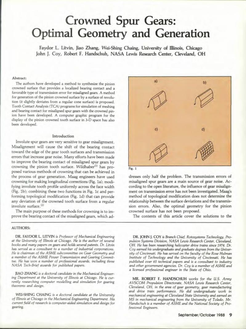
Misalignment will cause the shiH of the bearing contacttoward the edge of the gear tooth surfaces and transmissionerrors that increase gear noise. Many efforts have been madet,o improve the bearing contact of misaligned spur gears bycrowning the pinion tooth surface, WiJdhaber(1) has pro-posed various methods of crowning that can be achieved inthe process of gear generation. Maag engineers have usedcrowning for making longitudinal corrections [Fig.1a); modi-fying involute tooth profile unifonnly across the face width(Fig. Ib); combining 'these two functions in fig. Ie and per-fonning topological modification (Fig. Id) that can prov:ideany deviation of the crowned tooth surface from a regularinvolute surface. (2)
The main purpose of these methods for cr-owningis to im-prove the bearing contact of the misaligned gears, which ad-
a) b)
c) d)
Fig. 1
dresses only half the problem. The transmission errors ofmisaligned spur gears are a main source of gear noise ..Ac-cording to the open literature, 'the influence of gear misalign-ment on transmission error has not been inv,estigated.Maag'smethod. of topological modification does not determine therelationship between the surface deviations and the transmis-sion errors, Also, the optimal geometry for the pi.njoncrowned surface has not been proposed.
The contents of this article cover the solutions to the
AUTHORS:
DR. FAYDOR L. lITVIN.is Professor of Mechanical Engineeringat the University of Illinois at Chicago. He is the author of severa.1books and many papers on gears and holds several patents ..Dr. Litvinhas served as a consultant to a number of industrial corpor,UioTl5.He is chairman of the ASME subcommittee on Gear Geomefry anda member of the ASME Pouer Transmission and Gearing Commit-tee. He has won a number of professioMI awards, including threeNASA Tech-Brief ,awards for published papers.
MO .ZHANC is a doctoral candidate in the Mechanical Engineer-ing Department at the University of Illinois ,at Chicago. He is cur-rently researching computer modelling and simulation for gearingtheorems and design.
WEI~SHINC CHAING is a doctoral cllndidate at the Universityof Illinois at Chicago in the Mechanical Engineering Department. Hiscurrent field of research is computer"aided simulation and design forgearing.
DR.. JOHN ,. COY is Branch Chie!, Rotosystems Technol~gy, Pro-pulsion Systems Division, NASA Lewis Research Center, C1eue.1Dnd,OH. He has been~esearching helicopt.er d.rive trains since 1974. Dr ..CO'lIearned.his undergradl.lllte and grad'lJQtedegT'ees from the' U'niver-sityof Cincinnati. He has served on the faculty of the Rose' HillmanInstitute of T,echnology and the Ul'liveTSity of Cincinnati. He haspublished over 65 technical papers and is ,a consultant to ,industryand other government ,agencies..Dr. Coy is a member of A SME and.a licensed professional engineer in the State of Ohio,.
MR. ROBERT F. HANDSCHUH works for the u.s. ArmyAVSCOM Propulsion Directorate, NASA Lewis Research Center,Clevela.nd, OH, in the area of gear geometry, gear manufacturingand drive train performance. He did ,undergraduate work inmechanl'cal engineering at Cleveland State University and enmed' 1m
MS in mechanical engineering from the University of Toledo. Mr.Handschuhis a member of ASME and the National Society of Pro-fessional Engineers.
September/October 19,88 9
_______ ~ J
followmg problems: opdmalgeornetry ofa pinion crownedtooth surface; new method of crowning that is based on ap-plication of a tool. provided with a surface of revolution (thetool surface is slightly deviated from a cone surface); thedevelopment of TCA {Tooth Contact Analysis) programs forthe determination of transmission errors .for misaligned gearsand their bearing contact and a computer graphic programfor the display of the crowned surface and bearing contactin 3-D spaoe ..The first method of generation that providesthe desired optimal pinion 'tooth geometry is basedon theapplication of a computer controlled machine with fivedegrees of freedom ..The second method for generation needsonly a new tool. shape and is based on application of the ex-isting equipment.
The development of the optimal geometry of a pinioncrowned gear tooth surface is based on the followingconsiderations.
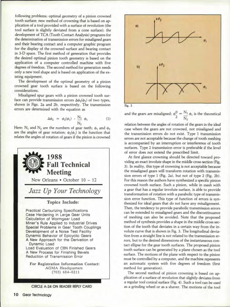
Misaligned spur gears with a pini.on crowned tooth sur-face can provide transmission errors .6.412(411)of two types,shown in. Figs. 2a and 2b,. respectively. The transmissionerrors are determined with the equation as
aq,2 = ~(q,1) - Nl. rbt (1)N2
Here: Nl and Nz are the numbers of gear Iteeth; q,,1 and q,2aile the angles of gear rotation; q"z(q,t) is the function thatrelates the angles of rotation of gears Hthe pinion is crowned
1988Fall TechnicalMeeting
New Orleans • October 10 - 12
Jazz Up Your TechnologyTopics Include:
Practical Carburizing SpecificationsCase Hardening in Large Gear UnitsCalculation of \lVormgear LoadMiner's Rule .Applied to Industrial DrivesSpecial Problems in Gear Tooth CouplingsIDevelopment of a Noise Test FacilitylDynamic Behavior of Epicyclic GearsA New Approach for the 'Derivation of
lDynamic LoadLoad Evaluation of CBN Finished Gears.A New Process for Finishing BevelsReduction of Transmission Error
For Reglstratlen Informatlon Conteet:AGMA Headquarters
(703) 684-0211
CIRCLE A-24 ON READER REPlY CA!RD
10 Gear Technology
a)
aq;2
~ /1 /'~v V ~I
b)
¢I
Fig. 2
and the gears are misaligned; 41,0= N1q,1 is the theoreticsl2 N2
relation between the angles of rotation of the gears in the idealcase where the gears are not crowned, not misaligned andthe transmission errors do not exist. Type 1 transmissionerrors are not acceptable because the change of tooth meshingis accompanied by an interruption or interference of toothsurfaces ..Type 2 transmission error is preferable if the levelof 'error does not extend the prescribed limit.
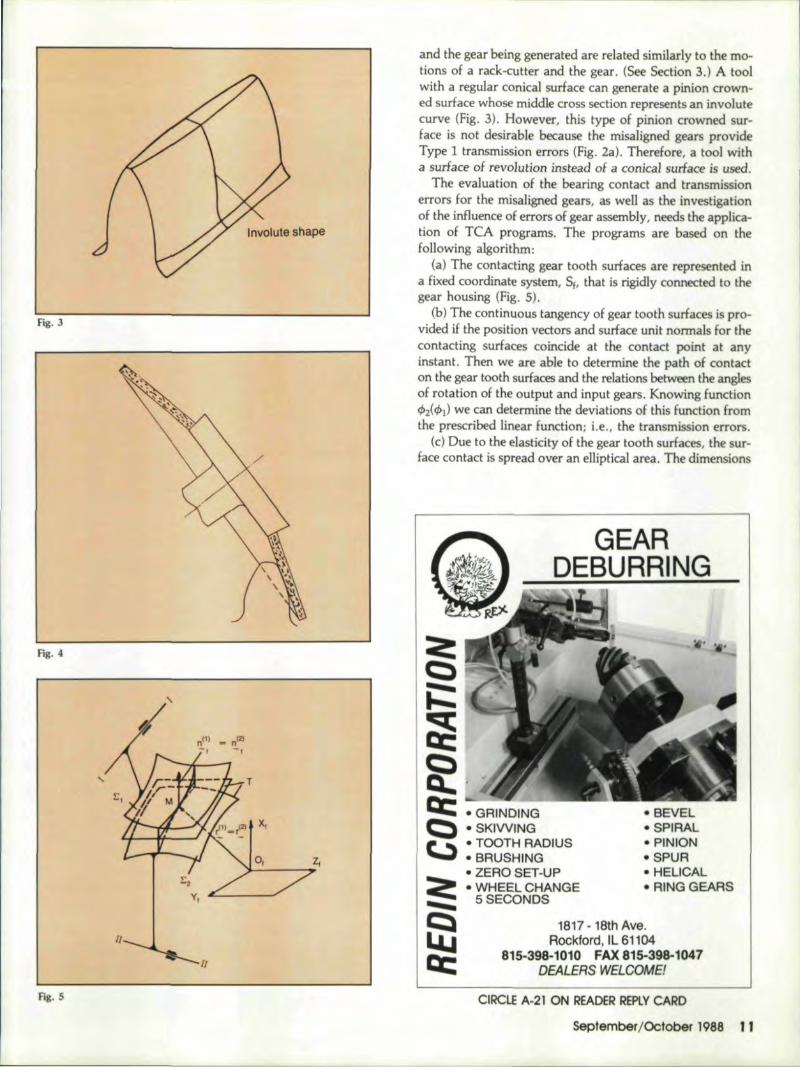
At first glance crowning should be directed toward pro-viding an exact involute shape in 'the middle cross section (Fig.3). In realjty, this ,type of crowning is not acceptable becausethe misaligned gears will transform rotation with transmis-sion errors of type 1 (Fig. 2a), but not of type 2 {Fig. 2b).For this reason the authors have synthesized a specific pinioncrowned tooth surface .. Sucha pinion,. while in mesh wi.tna. gear that has a regular involute surface, is able to providetransfonnation of rotation with a parabolic 'type of transmis-sion error function. This 'type of function of errors is syn-thesized for ideal gears that do not have any misalignment.Then, the tendency to provide parabolic transmission errorscan be extended Ito misaligned gears and the discontinuanceof meshing can also be avoided. Note that the proposedmethod of synthesis provides a shape in the middlecross sec-tion. of the tooth that deviates in a certain way from the in-volute curve that is shown in Fig. 3..The longitudinal devia-tion from a straight line is not related to the transmission er-rors, but to the desired dimensions of the instantaneous con-tact ellipse for the gear tooth surfaces. The proposed piniontooth surfacecan be generated by a plane chosen as the toolsurface. The rnotionsof 'the plane with respect to the pinionmust be controlled by a comput.er,and the machine representsan automatic system with five degrees of freedom (firstmethod for generation).
The second method of pinion crowning is based onap-plication of a surface of revolution that slightly deviates froma regular tool conical surface (Fig. 4). Such a tool can be usedlas a grinding wheel. or asa shaver. The motions of the tool
Involute shape
Hg.3
Fig .. 4
1/
11
Fig. 5,
and the gear being generated are related sim~larly to the mo-tions of a rack-cutter and the gear .. (See Section 3.) A toolwitha regular conical surface can generate a pini.on crown-ed surface whose middle cross section represents an involutecurve (Fig. 3). However, this type of pinion crowned sur-face is not desirable because the misaligned gea.rs provideType 1 transmission errors (Fig. 2a). Therefore, a tool witha surface of revo1ution instead of a conical surface is used.
The evaluation of the bearing contact and transmissionerrors for the misaligned gears, as well as the investigationof the influence of errors of gear assembly, needs the applica-tion of TCA programs. The programs are based on thefollowing algorithm:
(a) The contacting gear tooth suriacesare represented ina fixed coordinate system, Sf, thai! is rigidly connected to, 'thegear housing (Fig.. 5).
(b) The continuous tangency of gear tooth surfaces is pro-vided if the position vectors and surface unit normals for thecontacting surfaces coincide at the contact point at anyinstant. Then we are able to determine the path. of contacton the gear tooth surfaces and the relations between. the anglesof rotation of the output and input gears. Knowing function4>2(4)1) we can determine the deviations of this fundion fromthe prescribed linear function; i.e, the transmission errors.
(c) Due to the elasticity of the gear tooth surfaces, the sur-face contact is spread over an elliptical area ..The dimensions
::a:Q,~
~£1:''c:::iiQ.,'c:r: '.GFUNOINGQ, .SKIW,IINGr ....•TOOTH RAIDIUS...., • BRUSH liNG
• ZERO SI:T·UP~ • WHEEL. CHANGIE... , 5SECONDSI....... ,
I~IILLjICC
• BEVEL01 SPIRAL• PINIION·SPUA" HELICAL'. FUNGGEARS
1817 -18th Ave.RocKford, IL 61 "04
815~398~'010 FAX.815-398-1047.DEALERS WEL.OOMEI
CiIRCLE A~21 ON READER RERlY CARD
September/October 1988 11
a)
o
b)
Middle-crosssect.ion shape
a
tig.6
11l_GARA.r-r-I'"j!,s 941 MILITARY RD.
~ BUFFALO, NY 14217OVer 30 VealS Continuous Service to Industry
GEAR GRINDINGSPECIALISTS
- MFG,..ALL TYPES INCLUDING
---- - - - -
GEAIR CDR~
.• Spur• Helical··Internall• Pump Gears• Splines and Pulleys.• Serrations• Sprock·els and ,Ratchet
fype'Gears• Hobbing up to 24" in
iDiameter
• Complete Machining andGrinding Capability
• Includes: O.D.alld: I.D.Grinding', Gear Honingw/Crowning. Broaching,Keysealing. fuming andMilling, Tooth Chamler-ing,and Rounding
CALL NOW IFOR A QUOT,E• Supplied complete to print• Finishing operations on your blanks• Grind teeth only
FAX. (716)874--9003 • IPHON,E (71!6) 874-3131
12 Sear Technology
and orientation of the instantaneous contact ellipse dependon the principal curvatures and the principal directions ofthe contacting tooth surfaces. The bearing contact is deter-mined by the developed TCA program as the set of the con-tact ellipses that move over the contacting surfaces in the pre-cess of motion.
Synthesis of Pinion Crowned Tooth SurfaceConsider that the gear is provided with a regular involute
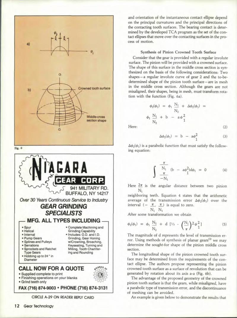
surface. The pinion will be provided with a crowned surface.The shape of this surface in the middle cross section is syn-thesized on the basis of the foHowing considerations: Twoshapes - a regular involute curve of gear 2 and the to-be-determined shape of the pinion tooth surface - are in meshin the middle cross section. Although the gears are notmisaligned,their shapes, being in mesh, must transform rota-tion with the function (Fig. 6a).
rp2{,rpl) ;;;;;; rp1 ~l + .a.rp2(rpl) =N2
arp21
Here: (2)
(3)
.tlr.b2(rpl) is a parabolic function that must satisfy the follow~ingequation :.
11"
1 N1 (b - arp2)dr.bl = 0 (4)11" 1
-Nt
Here 211"is the angular distance between two pinionNl
neighboring teeth. Equation 4: states that the arithmeticaverage of the transmission error tlrp2(·tPl) over theinterval (- 11', _!J is equal to zero.
N1 NIAfter some transformation we obtain
tPZ(rpl) = rpl NN1 + d [113 - (Nl)2r.b~]'2 7T
The magnitude of d represents the level of transmission er-ror. Using methods of -synthesis of planar gears(3) we maydetermine the sought-for shape of the pinion middle crosssection.
The longitudinal shape of the pinion crowned tooth sur-face may be determined from the requirements of the con-tact ellipse. The authors propose representing the pinioncrowned tooth surface as a surface of revolution that can begenerated by rotation about its axis a-a (Fig. 6b).
The advantage of the proposed geometry of the crownedpinion tooth surface is that ~thegears, while misaligned, havea parabolic type of transmission error, and the discontinuanceof meshing can be avoided.
An example is given below to demonstrate the results that
(5)
can be obtained through use of the proposed crowningmethod.Example 1
Given: numbers of teeth: N) = 20, N2 = 40; diametralpitch, P = 10 1; pressure angle tc = 20°. The pinion
in
tooth surface has been designed as a crowned surface witha parabolic tr,ansmission error maximum d = 2 arc secondsin the aligned condition. The developed TeA program hasbeen applied for the evaluation of transmission errors for thefollowing misalignments:
(i) The change of the center distance is 4C = 1%. Thec
gear axes are not parallel, but crossed, and the screw angleis five arc minutes. The function of transmission errors causedby the misalignments mentioned above is of a parabolic type.and it is represented in. Table L The maximal value oftransmission errors is 1.2 arc seconds.
(iii) The gear axes are not parallel, but intersected. and formthe angJe (l = 5 arc minutes. The function of transmissionerrors is of a. parabolic type. and the maximal! value oftransmission errors is 2.0 arc seconds (Table 2).
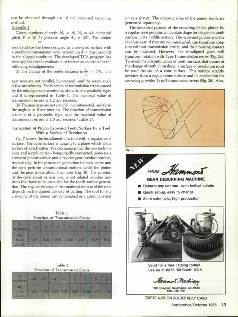
Generation of Pinion Crowned. Tooth Surface by a ToolWith a Surfaoe of Revolution
Fig. 7 shows the installment of a tool with a regular conesurface. The cone surface is tangent toa plan.e whi.ch is thesurface of a rack cutter. We can imagine that the two tools - acone and a, rack cut ter - being .rigidlyconnected, generate a.crowned pinion surface and a regular gear involute surface,r,espectively. In the process of generation the rack cutter andthe cone perlorma translational motion, while the pinionand the gear rotate about their axes (Fig. 8). The rotationof the con about i1s axis, C-C, is not related to other mo-tions thae have to be provided for the tooth surface genera-tion. The angular velocity in the rotational motion of the conedepends on the desired velocity of cutting ..The tool for thecrowning of the pinion can be designed as a grinding wheel
Table 1function '0£ Transmission Errors
Table .2
or as a shaver. The opposite sides of t.he pinion tooth aregenerated separately.
The described process of the crnwning of the pinion bya regelarcone provides an involute shape for the pinion toothsurface in its middle section. Th crowned pinion and theinvolute gear. if they are not misaligned. can transform rota-tion without transmission errors, and their bearing c,ontactcan be localized. However. the misaligned gears willtransform rotation with Type 1 transmission errors (Fig. 231).To avoid the disoontinuance of tooth surfaces that occurs atthe change of teeth in meshing. a surface of revolution mustbe used instead of a. cone surface, This surface slightlydeviates tram a regular cone surface and its application forcrowning provides Type 2 transmission errors (Fig. 2b). Also.
Fig. 7
FROM,~
IGEAR DEBURRIING MACHINE., Deburrs any contour, even hellcallsplrals
.1 Quick set· UP', easy to change
• Semil·automatlc, h,lgh production
Send for a free, catalog todayJSee us at IMrS '88 Booth 6316.
~;?f~,-.-_. ,.-.-~-"'i:.l1600 IDo\!glu, KalIIIIUOO. MI >40007
616 f 345-7151
CIRCLEA-28 ON IREADER IREPLY CARD
Septem'ber/October 1988 113
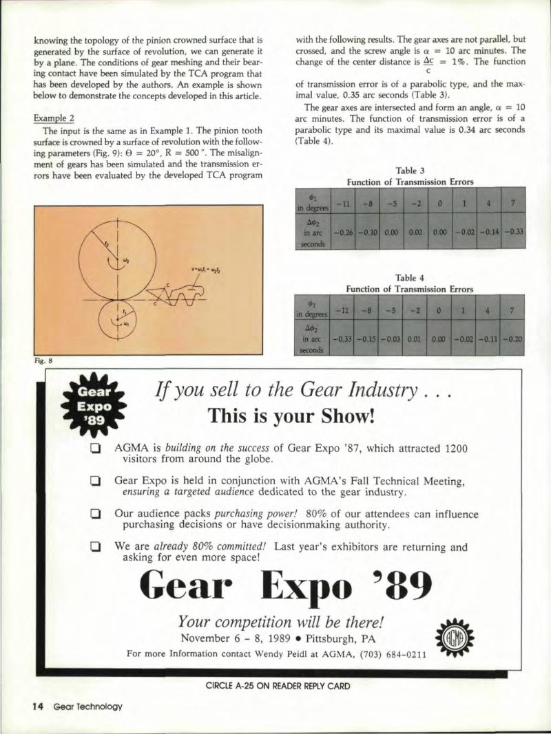
knowing the topology of the pinion crowned surface that isgenerated by the surface of revolution, we can generate itbya plane. The conditions of gear meshing and their bear-ingcontact have been simulated by the TCA program thathas been developed by the authors. An example is shownbelow to demonstrate the concepts developed in this article.
Example 2The input is the same as in Example 1. The pinion tooth
surface is crowned by a surface of revolution with the follow-ing parameters (Fig. 9): e = 20°, R = 500 ", The misalign-ment of gears has been simulated and the transmission er-rors have been evaluated by the developed TCA program
Fig. 8
If you sell to the Gear IndustryThis is your Show!
with the following results. The gear axes are not parallel, butcrossed, and the screw angle is a = lOarc minutes. Thechange of the center distance is .8.c = 1%. The function
cof transmissionerror is of a parabolic type, and the max-imal value, 0.35 arc seconds (Table 3) ..
The gear axes are intersected and form an angle, a = 10arc minutes. The function of transmission error is of aparabolic type and its max ..imal value is 0.34 arc seconds(Table4).
Table 3
Table 4
o AGMA is building on the success of Gear Expo '87, which attracted 1200visitors from around the globe.
D Gear Expo is held in conjunction with AGMA's FaH Technical Meeting,ensuring a targeted audience dedicated to the gear industry.
D Our audience packs purchasing power! 80% of our attendees can influencepurchasing decislons or have decisionmaking authority.
Q We a.re already 80% committed! Last year's exhibitors are returning andasking for even more space!Gear Expo '89
Your competition will be there! •.. -November 6 - 8, 198ge Pittsburgh, PA ~-
For more Information contact Wendy Peidl at AGMA. (703) 684-0211 _. ....... •
1'4 Gear Technology
CIRCLE A-25 ON READERREPLYCARD
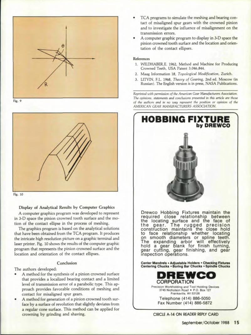
Fig. 10
Display o.f Analytical. Resullts iby Computer GraphicsA computer graphics program was developed to represent
in 3-D space the pinion crowned tooth surface and the mo-tion of the contact ellipse in the process of meshing ..
The graphics program is based on the analytical. solutionsthat have been obtained from the TCA program. It producesthe intricate high resolution picture on a graphic terminal andlaser printer. Fig. 10 shows the results of the computer graphicprogram that represents the pinion crowned surface and thelocation and orientation of the contact ellipses.
ConclusionThe authors devdoped:" A method for the synthesis .of a pinion crownedsurface
,that provides a localized beariagcontact and a limitedlevel of transmission error ofa parabolic type. This ap-proach provides favorable conditions of meshing andcontact for misaligned Spill gears.
• A method for generation of a pinion crowned tooth sur-face by a surface of revolution that slightly deviates froma regular cone surface. This method can be applied fercrowning by grinding and shaving.
" TeA programs to simulate the meshing and bearing 'con-tact of misaligned spur gears with th~ crowned pinienand to investigate the influence .of misalignment on thetransmission errors ..A computergraph:ic program to display in 3-D space thepinion crowned tooth surface and the Jecation and orien-tation of the contact ellipses.
•
References1. WILDHABER,E. 1962, Method and Ma.chine for Pr,oducing
Crowned Teeth. USA Patent 3.046,844.2.. Maag Information 18, Topological MDdjfica~jon. Zurich.3.. lITVIN, F.L. 1968, Theory of Gearing, 2nd ed, Moscow (.in
Russian). The English version is in press, NASA Publications.
Reprinted with permission of tire American Gew Mmll~fQclUFflrs Association.The opinions, statements Qlul conclusiom presented in this article are thoSl'of the authors and in noway represent the position or opinion of theAMERICAN GEAR MANUFACTURERS ASSOClA'HON.
Drewco Holblbing IFIil:l(tur,esmaintain ther~quilre_C!..~clos,e .~elationshilP betw.eenthe looatllng surface ,andltihe falce ofthe 'g,ealr. Tlhle rUlgged precjstenconstruction rnatntalns uhe close holdto face retatlonshlp whether locatingon smooth diameters or spline teetli.The expanding a..rbee w.iII. ~ff,ectiyelyhotd a gear fllankfor flnlSh, turnmg,gear cuning. glearfinishiin,g, and giea:rInspection operations. -
Center Mandrell •.Adjullable HoldeN • checkinGI Flfiu ....Centering Chuc:kl • 80rln1l118.r'CIUICkl • Splndlel Chuclu
!DREW'C'DCO.R:P.QR:A.TION - -
Precision Workholdlngl and Tool Holding Devices3745 NichOlson Road • P.O. Box 127
Franksville, WI 53126
Telephone (414) 886-5'050IFax iNumiber (414)886~5872
OIOCIJE A-14 ON IREADER' REPLY CARD
September/OCtober 1988 15,