
Crosslayer Survivability in Overlay-IP-WDM Networks
127
CROSSLAYER SURVIVABILITY IN OVERLAY-IP-WDM NETWORKS by Peera Pacharintanakul B.Eng. in EE, Chulalongkorn University, Thailand, 2000 M.S. in EE, Washington University, St. Louis, MO, 2004 Submitted to the Graduate Faculty of the Graduate Telecommunications and Networking Program in partial fulfillment of the requirements for the degree of Doctor of Philosophy University of Pittsburgh 2010
Transcript of Crosslayer Survivability in Overlay-IP-WDM Networks
CROSSLAYER SURVIVABILITY IN
OVERLAY-IP-WDM NETWORKS
by
Peera Pacharintanakul
B.Eng. in EE, Chulalongkorn University, Thailand, 2000
M.S. in EE, Washington University, St. Louis, MO, 2004
Submitted to the Graduate Faculty of
the Graduate Telecommunications and Networking Program in
partial fulfillment
of the requirements for the degree of
Doctor of Philosophy
University of Pittsburgh
2010
UNIVERSITY OF PITTSBURGH
SCHOOL OF INFORMATION SCIENCES
This dissertation was presented
by
Peera Pacharintanakul
It was defended on
July 20, 2010
and approved by
Associate Professor David Tipper, Ph.D., University of Pittsburgh
Associate Professor Prashant Krishnamurthy, Ph.D., University of Pittsburgh
Professor Richard Thompson, Ph.D., University of Pittsburgh
Yu Liu, Ph.D., Juniper Networks
Associate Professor Eytan Modiano, Ph.D., Massachusetts Institute of Technology
Dissertation Director: Associate Professor David Tipper, Ph.D., University of Pittsburgh
ii

Copyright c© by Peera Pacharintanakul
2010
iii

CROSSLAYER SURVIVABILITY IN OVERLAY-IP-WDM NETWORKS
Peera Pacharintanakul, Ph.D.
University of Pittsburgh, 2010
As the Internet moves towards a three-layer architecture consisting of overlay networks on
top of the IP network layer on top of WDM-based physical networks, incorporating the inter-
action between and among network layers is crucial for efficient and effective implementation
of survivability.
This dissertation has four major foci as follows: First, a first-of-its-kind analysis of the
impact of overlay network dependency on the lower layer network unveils that backhaul, a
link loop that occurs at any two or more lower layers below the layer where traffic is present,
could happen. This prompts our proposal of a crosslayer survivable mapping to highlight such
challenges and to offer survivability in an efficient backhaul-free way. The results demonstrate
that the impact of layer dependency is more severe than initially anticipated making it clear
that independent single layer network design is inadequate to assure service guarantees and
efficient capacity allocation. Second, a forbidden link matrix is proposed masking part of
the network for use in situations where some physical links are reserved exclusively for a
designated service, mainly for the context of providing multiple levels of differentiation on the
network use and service guarantee. The masking effect is evaluated on metrics using practical
approaches in a sample real-world network, showing that both efficiency and practicality can
be achieved. Third, matrix-based optimization problem formulations of several crosslayer
survivable mappings are presented; examples on the link availability mapping are particularly
illustrated. Fourth, survivability strategies for two-layer backbone networks where traffic
originates at each layer are investigated. Optimization-based formulations of performing
recovery mechanisms at each layer for both layers of traffic are also presented. Numerical
iv

results indicate that, in such a wavelength-based optical network, implementing survivability
of all traffic at the bottom layer can be a viable solution with significant advantages.
This dissertation concludes by identifying a roadmap of potential future work for cross-
layer survivability in layered network settings.
Keywords: Capacity allocation, Multilayer network, Multilayer traffic, Network surviv-
ability, Traffic survivability.
v
TABLE OF CONTENTS
PREFACE . . . . . . . . . . . . . . . . . . . . . . . . . . . . . . . . . . . . . . . . . xiv
1.0 INTRODUCTION . . . . . . . . . . . . . . . . . . . . . . . . . . . . . . . . . 1
1.1 MOTIVATION . . . . . . . . . . . . . . . . . . . . . . . . . . . . . . . . . 1
1.2 CONTRIBUTIONS . . . . . . . . . . . . . . . . . . . . . . . . . . . . . . . 4
1.3 DISSERTATION OVERVIEW . . . . . . . . . . . . . . . . . . . . . . . . . 5
2.0 RELATED LITERATURE . . . . . . . . . . . . . . . . . . . . . . . . . . . . 8
2.1 GRAPH THEORETIC APPROACHES TO SURVIVABLE MAPPING . . 9
2.1.1 Graph Contraction . . . . . . . . . . . . . . . . . . . . . . . . . . . 9
2.1.2 Graph Coloring . . . . . . . . . . . . . . . . . . . . . . . . . . . . . 10
2.2 RECOVERY TECHNIQUES . . . . . . . . . . . . . . . . . . . . . . . . . . 11
2.2.1 Recovery Choices . . . . . . . . . . . . . . . . . . . . . . . . . . . . 12
2.2.1.1 Survivability at What Layers . . . . . . . . . . . . . . . . . 13
2.2.1.2 Sequential vs. Integrated . . . . . . . . . . . . . . . . . . . 13
2.2.1.3 Uncoordinated vs. Coordinated . . . . . . . . . . . . . . . . 13
2.2.1.4 Resources Held vs. Released . . . . . . . . . . . . . . . . . . 14
2.2.1.5 Segment vs. Path-based . . . . . . . . . . . . . . . . . . . . 14
2.2.2 Computational Approaches . . . . . . . . . . . . . . . . . . . . . . . 14
2.2.2.1 Offline vs. Online . . . . . . . . . . . . . . . . . . . . . . . . 14
2.2.2.2 Capacity Allocation vs. Reservation . . . . . . . . . . . . . 14
2.2.2.3 Peak Demand vs. Multi-Hour Model . . . . . . . . . . . . . 15
2.2.3 Protection Strategies in Multilayer Networks . . . . . . . . . . . . . 15
2.2.3.1 Escalation Strategies . . . . . . . . . . . . . . . . . . . . . . 15
vi
2.2.3.2 Disjointness Paradigms . . . . . . . . . . . . . . . . . . . . 15
2.3 SURVIVABILITY IN MULTILAYER IP-OVER-WDM NETWORKS . . . 17
2.3.1 Survivability at the Top Layer . . . . . . . . . . . . . . . . . . . . . 18
2.3.2 Survivability at the Bottom Layer . . . . . . . . . . . . . . . . . . . 18
2.3.3 Survivability at Both Layers . . . . . . . . . . . . . . . . . . . . . . 19
2.4 SURVIVABILITY IN OVERLAY NETWORKS . . . . . . . . . . . . . . . 19
2.5 DIFFERENTIATED SURVIVABILITY . . . . . . . . . . . . . . . . . . . . 20
3.0 THE BACKHAUL PROBLEM IN LAYERED NETWORK
ARCHITECTURES . . . . . . . . . . . . . . . . . . . . . . . . . . . . . . . . 22
3.1 BACKHAUL MAPPING . . . . . . . . . . . . . . . . . . . . . . . . . . . . 22
3.1.1 Network Layer . . . . . . . . . . . . . . . . . . . . . . . . . . . . . . 22
3.1.1.1 Network Link Mapping . . . . . . . . . . . . . . . . . . . . 23
3.1.1.2 Network Node Mapping . . . . . . . . . . . . . . . . . . . . 25
3.2 BACKHAUL ROUTING . . . . . . . . . . . . . . . . . . . . . . . . . . . . 25
3.2.1 Traffic Layer . . . . . . . . . . . . . . . . . . . . . . . . . . . . . . . 25
3.2.1.1 Direct/Primary Traffic Flow Routing . . . . . . . . . . . . . 26
3.2.1.2 Indirect/Backup Traffic Flow Routing . . . . . . . . . . . . 26
3.3 SUMMARY . . . . . . . . . . . . . . . . . . . . . . . . . . . . . . . . . . . 27
4.0 CROSSLAYER SURVIVABLE MAPPING . . . . . . . . . . . . . . . . . 28
4.1 INTRODUCTION . . . . . . . . . . . . . . . . . . . . . . . . . . . . . . . 28
4.2 MOTIVATION . . . . . . . . . . . . . . . . . . . . . . . . . . . . . . . . . 28
4.3 PROBLEM STATEMENT . . . . . . . . . . . . . . . . . . . . . . . . . . . 29
4.3.1 Notation Used . . . . . . . . . . . . . . . . . . . . . . . . . . . . . . 29
4.3.2 An Optimization-based Formulation . . . . . . . . . . . . . . . . . . 31
4.4 NUMERICAL RESULTS AND ANALYSIS . . . . . . . . . . . . . . . . . . 36
4.4.1 Metric 1: Capacity Overbuilding . . . . . . . . . . . . . . . . . . . . 38
4.4.2 Metric 2: Flow Overrouting . . . . . . . . . . . . . . . . . . . . . . 39
4.4.3 Metric 3: Link Overusing . . . . . . . . . . . . . . . . . . . . . . . . 40
4.5 CASE STUDY: RING OVERLAY NETWORK . . . . . . . . . . . . . . . 41
4.6 SUMMARY . . . . . . . . . . . . . . . . . . . . . . . . . . . . . . . . . . . 44
vii

5.0 DIFFERENTIATED CROSSLAYER NETWORK MAPPING . . . . . 46
5.1 INTRODUCTION . . . . . . . . . . . . . . . . . . . . . . . . . . . . . . . 46
5.2 BACKGROUND . . . . . . . . . . . . . . . . . . . . . . . . . . . . . . . . 47
5.2.1 Use of Topology Knowledge in Overlay Networks . . . . . . . . . . . 47
5.2.2 Use of Topology Knowledge in IP-over-WDM Networks . . . . . . . 49
5.3 NETWORK MODEL AND PROBLEM DESCRIPTION . . . . . . . . . . 50
5.3.1 Forbidden Link Matrix . . . . . . . . . . . . . . . . . . . . . . . . . 51
5.3.2 Service Overlay Network . . . . . . . . . . . . . . . . . . . . . . . . 54
5.3.3 Infrastructure Network . . . . . . . . . . . . . . . . . . . . . . . . . 57
5.4 NUMERICAL EVALUATION . . . . . . . . . . . . . . . . . . . . . . . . . 59
5.4.1 Mapping First Survivability . . . . . . . . . . . . . . . . . . . . . . 60
5.4.2 Routing First Survivability . . . . . . . . . . . . . . . . . . . . . . . 62
5.4.3 Joint Mapping-Routing Survivability . . . . . . . . . . . . . . . . . 63
5.5 SUMMARY . . . . . . . . . . . . . . . . . . . . . . . . . . . . . . . . . . . 63
6.0 LINK AVAILABILITY NETWORK MAPPING . . . . . . . . . . . . . . 65
6.1 INTRODUCTION . . . . . . . . . . . . . . . . . . . . . . . . . . . . . . . 65
6.2 TERMINOLOGY AND PROBLEM DEFINITION . . . . . . . . . . . . . 68
6.2.1 Terminology . . . . . . . . . . . . . . . . . . . . . . . . . . . . . . . 68
6.2.2 Problem Definition . . . . . . . . . . . . . . . . . . . . . . . . . . . 69
6.3 MATRIX FORMULATIONS OF SURVIVABLE MAPPING . . . . . . . . 69
6.3.1 Notation . . . . . . . . . . . . . . . . . . . . . . . . . . . . . . . . . 69
6.3.2 Guaranteed Network Mapping . . . . . . . . . . . . . . . . . . . . . 70
6.3.2.1 Network Mapping for Single-Link Failures . . . . . . . . . . 70
6.3.2.2 Network Mapping for n-Link Failures . . . . . . . . . . . . . 71
6.3.2.3 Max-Min Survivable Network Mapping . . . . . . . . . . . . 72
6.3.3 Optimized Network Mapping . . . . . . . . . . . . . . . . . . . . . . 73
6.3.4 Constrained Network Mapping . . . . . . . . . . . . . . . . . . . . . 74
6.3.5 Solving the Optimization Problems . . . . . . . . . . . . . . . . . . 74
6.4 DETAILED SAMPLE RESULTS . . . . . . . . . . . . . . . . . . . . . . . 75
6.5 SUMMARY . . . . . . . . . . . . . . . . . . . . . . . . . . . . . . . . . . . 79
viii

7.0 SURVIVABILITY OF MULTILAYER TRAFFIC . . . . . . . . . . . . . 80
7.1 INTRODUCTION . . . . . . . . . . . . . . . . . . . . . . . . . . . . . . . 80
7.1.1 Motivation . . . . . . . . . . . . . . . . . . . . . . . . . . . . . . . . 80
7.1.2 The Proposed Evaluation Approach . . . . . . . . . . . . . . . . . . 81
7.2 SURVIVABILITY OF TWO-LAYER TRAFFIC . . . . . . . . . . . . . . . 82
7.2.1 Providing Backup Paths to Top-Layer Traffic at the Bottom Layer . 83
7.2.2 Providing Backup Paths to Bottom-Layer Traffic at the Bottom Layer 85
7.2.3 Providing Backup Paths to Top-Layer Traffic at the Top Layer . . . 86
7.3 NUMERICAL RESULTS AND ANALYSIS . . . . . . . . . . . . . . . . . . 87
7.3.1 Impacts of Traffic Ratios . . . . . . . . . . . . . . . . . . . . . . . . 88
7.3.1.1 Varying Top-Layer Flows . . . . . . . . . . . . . . . . . . . 88
7.3.1.2 Varying Bottom-Layer Flows . . . . . . . . . . . . . . . . . 90
7.3.2 Impacts of Network Connectivity . . . . . . . . . . . . . . . . . . . 92
7.3.3 Deployment Issues . . . . . . . . . . . . . . . . . . . . . . . . . . . 93
7.4 SUMMARY . . . . . . . . . . . . . . . . . . . . . . . . . . . . . . . . . . . 93
8.0 CONCLUSIONS AND FUTURE WORK . . . . . . . . . . . . . . . . . . 96
8.1 DISSERTATION SUMMARY . . . . . . . . . . . . . . . . . . . . . . . . . 96
8.2 FUTURE WORK . . . . . . . . . . . . . . . . . . . . . . . . . . . . . . . . 99
8.3 CONCLUSIONS . . . . . . . . . . . . . . . . . . . . . . . . . . . . . . . . 101
APPENDIX. A TAXONOMY OF CROSSLAYER SURVIVABILITY IN
LAYERED NETWORKS . . . . . . . . . . . . . . . . . . . . . . . . . . . . . 102
BIBLIOGRAPHY . . . . . . . . . . . . . . . . . . . . . . . . . . . . . . . . . . . . 104
ix

LIST OF TABLES
2.1 Survivability issues in layered networks . . . . . . . . . . . . . . . . . . . . . 9
6.1 Optimum crosslayer survivable mapping of the three-layer network in Figure 6.1 67
6.2 Availability and cost of mapping schemes . . . . . . . . . . . . . . . . . . . . 78
7.1 Resource overbuilding of optimal spare capacity in multilayer traffic scenarios 95
8.1 Summary of contributions . . . . . . . . . . . . . . . . . . . . . . . . . . . . 97
8.2 Crosslayer connectivity metrics for survivable layered networks . . . . . . . . 100
x

LIST OF FIGURES
1.1 A sample two-layer sub-network of a layered network . . . . . . . . . . . . . 2
1.2 Dissertation roadmap and content dependency chart . . . . . . . . . . . . . . 6
2.1 Recovery choices in layered networks . . . . . . . . . . . . . . . . . . . . . . 12
3.1 Backhaul mapping in a three-layer network . . . . . . . . . . . . . . . . . . . 24
3.2 Backhaul example in a three-layer network . . . . . . . . . . . . . . . . . . . 26
4.1 The 14-node, 21-link NSFNet . . . . . . . . . . . . . . . . . . . . . . . . . . . 37
4.2 The 14-node, 46-link overlay network . . . . . . . . . . . . . . . . . . . . . . 37
4.3 Capacity overbuilding of the overlay network . . . . . . . . . . . . . . . . . . 38
4.4 Flow overrouting of the overlay network . . . . . . . . . . . . . . . . . . . . . 40
4.5 Link overusing of the overlay network . . . . . . . . . . . . . . . . . . . . . . 41
4.6 Capacity overbuilding of the ring overlays . . . . . . . . . . . . . . . . . . . . 42
4.7 Flow overrouting of the ring overlays . . . . . . . . . . . . . . . . . . . . . . 43
4.8 Link overusing of the ring overlays . . . . . . . . . . . . . . . . . . . . . . . . 44
4.9 Resource overbuilding of the ring overlays . . . . . . . . . . . . . . . . . . . . 45
5.1 A use case example of forbidden link matrix in a layered network . . . . . . . 52
5.2 Network and link mapping matrix H21 of multileveled service class r . . . . . 53
5.3 The 12-node, 18-link Polska network . . . . . . . . . . . . . . . . . . . . . . . 59
5.4 Flow blocking in mapping first survivability . . . . . . . . . . . . . . . . . . . 61
5.5 Resource overbuilding in routing first survivability . . . . . . . . . . . . . . . 62
6.1 The three network layers, constituting an overlay-IP-WDM network . . . . . 66
6.2 Availability-based network mapping in a layered network . . . . . . . . . . . 76
7.1 Top-layer flows vs. resource overbuilding (|F b| = 45) . . . . . . . . . . . . . . 89
xi

7.2 Bottom-layer flows vs. resource overbuilding (|F t| = 8) . . . . . . . . . . . . 91
7.3 Resource overbuilding in networks with top-layer connectivities (|F b| = 45) . 92
8.1 An illustration of the summary of contributions . . . . . . . . . . . . . . . . 98
xii

LIST OF ABBREVIATIONS
ATM Asynchronous transfer mode
CO Capacity overbuilding
CSM Crosslayer survivable mapping
FB Flow blocking
FO Flow overrouting
GMPLS Generalized multi-protocol label switching
ILP Integer linear programming
IP Internet protocol
ISP Internet service provider
JCA Joint capacity allocation
JCA3L Joint capacity allocation in three-layer networks
LO Link overusing
OCh-S Optical channel section
OMS Optical multiplex section
RO Resource overbuilding
SBPP Shared-backup path protection
SCA Spare capacity allocation
SDH Synchronous digital hierarchy
SON Service overlay network
SRLG Shared risk link group
WDM Wavelength-division multiplexing
xiii

PREFACE
I would like to acknowledge everyone whose path has crossed mine, whether our paths met
and then diverged or merged into one. This completion would not have been possible without
their assistance or efforts. Most importantly, I offer my deepest gratitude to my advisor, Dr.
David Tipper, for his invaluable guidance, his moral and financial support, as well as for the
specific direction provided in the course of developing this dissertation, all the while giving
me the right amount of freedom to explore research issues and to find the one I am most
passionate about. I have been very fortunate to have such a supportive and patient advisor.
I am also truly grateful to my dissertation committee members: Dr. Prashant Krishna-
murthy, for giving me research advice in his project-based course and offering gracious and
kind support throughout the whole course of study; Dr. Richard Thompson, for sharing
his wisdom and cautious view on the current status of IP communications; Dr. Yu Liu,
for spending hours discussing his past research experiences as well as current practical per-
spectives as part of the industry; and Dr. Eytan Modiano for diverting my thinking along
new paths during the dissertation proposal ultimately allowing a more accurate and concise
reporting of this research. The work of Drs. Liu and Modiano has been the primary inspi-
rational source for this work; it is an honor for me that each agreed to serve as a member of
my dissertation committee.
In addition to the members of my dissertation committee, I would like to take this
opportunity to express my humble appreciation to Professor Mihaela van der Schaar for
showing me the value of hard work and dedication, and Professor Chen-Nee Chuah for
teaching me the importance of novelty and creativity.
I also gratefully acknowledge Dr. Poompat Saengudomlert for his constructive criticism
and technical feedback as a dissertation reader; Janine Carlock for her terrific editing advice
xiv

and sincere interest in helping me out on some earlier drafts that have become part of this
dissertation; and Mark Steggert and Jace Schivins for their work in maintaining the computer
servers and providing IT support promptly.
On the non-academic side, I am indebted to all my friends for making my time of gradu-
ate studies an unforgettable experience. Though I cannot list them all, I want to particularly
thank Natthapong Liamcharoen, Worawan Arparatana, Phawit Putprasert, Suvimol Sangka-
tumvong, Aki Motohara, Nattapol Sitthimahachaikul, Siriwat Sakhonwasee, Fatos A. Peci,
Pornsri Khlangwiset, and my office mate, Tae-Hoon Kim, for offering help and support.
This dissertation would not be possible without the full financial support of a TOT Grad-
uate Fellowship, Royal Thai Government; a Predoctoral Fellowship, Office of the Provost,
University of Pittsburgh; and various other teaching and research assistantships throughout
my graduate years. In particular, I gratefully thank Dr. David Tipper, Dr. Martin B.H.
Weiss, and the Center for Russian and East European Studies (REES) for offering me the
research assistantship to work on a USAID-funded project.
Finally, I cannot express enough gratitude to my parents, Pornchai and Ninrat, and my
sister, Pam. I thank them for their constant support and optimism in me. I also thank
Patcharavipa Chaijuckam for being an endless source of moral support and patience, and
thank the Chaijuckam family for their spiritual support and generosity.
xv

1.0 INTRODUCTION
1.1 MOTIVATION
The phenomenal growth of the Internet is partly explained by the proliferation of under-
lying optical WDM technologies providing high bandwidth physical connectivity and the
overlaying applications. The notion of a multi-layer technology system has long been used
in telecommunication networks to describe the network architecture. Examples include an
ATM-over-SDH [1], ATM-over-SDH-over-WDM [2], [3], IP-over-SDH [4], IP-over-ATM-over-
SDH-over-WDM [4], IP-over-MPLS-over-WDM [5], IP-over-OTN network [6], a virtual light-
path network on a WDM-based network [7], [8], and the classic dial-up modem Internet access
over a PSTN. Due to business considerations, sharing information, e.g., topology, path per-
formance, among Internet service providers (ISPs) is limited in practice. As a result, overlay
networks have emerged as a means to connect a service and maintain its quality across
multiple ISPs. Note that each overlay is normally administered under a single management
group; the ease of operation and construction has encouraged a wide variety of overlay ser-
vices to emerge. In this work, we consider a network of overlay services on top of the IP over
WDM technologies as a layered network example; however, our work is also applicable to
any layered networks in general. Many studies have examined the Internet architecture, but
recent research has led us to consider a network of three layers, overlay-over-IP-over-WDM,
as the likely future Internet architecture.
In this architecture, overlay nodes are attached to an IP router. IP routers are associated
with an optical WDM switch; the switches are then interconnected by multi-wavelength fibers
capable of carrying a number of transmission channels. Recognizing the lower two network
layers, IP and WDM, each IP route is established by one or more lightpaths that span across
1

Figure 1.1: A sample two-layer sub-network of a layered network
fibers and occupies one or more wavelengths in each fiber. These two layers constitute the
Internet backbone in the optical Internet. Interdependency of failures, routing, topology
distribution, and signaling protocols between the two layers are still major concerns; however,
thanks to the vertical integration of IP and WDM technologies in the backbone network,
these two-layer networks can now be supported by GMPLS mechanisms acting as a glue
layer for the two technology environments.
In general multiple layers present a number of survivability problems. First, failures at
the bottom may tear down services at the top layer. This effect is called failure propagation
and is at the forefront of problems in multilayer survivability. Survivable mapping, a map of
a top-layer topology over a bottom-layer topology such that link failures at the bottom do
not disconnect the top-layer topology, is a way to avoid failure propogation. Link mapping
is almost always developed in anticipation of a single link failure [8]; however, reference [9]
has recently developed a mapping for multiple link failures.
Failures at the IP layer may occur for several reasons. One of them is related to failures
at the WDM optical layer such as node or link failures; an optical-related failure can result
in many failures at the IP layer. This effect is again regarded as failure propagation, the
2

severity of which is partly because of improper IP-to-WDM link mapping. Such a link
mapping tells us on which of the lightpaths an IP path is routed. Reference [10] reveals
that, in a highly-meshed operational IP network, this ill-chosen mapping contributes up to
9.12 percent of all unplanned failures that affect the IP traffic. The figure is likely to be
higher in partial-meshed IP networks as it increases the chance of network partitioning or
reduces the number of rerouting choices when a backup path is needed or failures happen.
More interestingly, the authors also discover that, on average 8 WDM links and 7 nodes
are shared by failed IP paths; these high numbers increase the chance of failures. In such
circumstances, the need for good link mapping to mitigate the worst consequences of failures
is obvious.
A second problem is, for a given mapping function, a top-layer path may require more
or less bandwidth from the perspective of the top layer than that of the bottom, depending
on which layer determines the capacity allocation and routing assignment. Depending on
how the top-layer path (1,2) is mapped and routed in the bottom layer, it can have different
capacity requirements. For example, as can be seen in Figure 1.1, if the path (1,2) needs
one unit of capacity at layer 2 and it is routed at the bottom layer on the (1,2) link then
only one unit of capacity at the bottom layer is required. However, if the layer 2 link (1,2)
is routed along links (1,8) and (8,2) in the bottom layer, two units of capacity are consumed
by the top-layer path (1,2).
Failure propagation also imposes difficulty in the network design phase as to deciding, for
each top-layer path, which layer is responsible for failure recovery and under what conditions.
This is because for a top-layer primary path, a backup path can be provided in either layer.
Recovery mechanisms may also be redundant between two layers; however, this does not
automatically imply that all of the mechanisms are used at both layers [2]. In addition, since
the capacity of a bottom link can simultaneously be shared by many top paths, allocating
capacity among their corresponding backup paths in two layers becomes a concern; the
services provided by the top-layer network must be survivable under failures at the bottom.
Capacity allocation ensures sufficient link capacity for rerouting traffic in the face of failures.
Routing assignment guarantees that the end-to-end requirements are met, e.g., availability,
delay, etc. In practice, dynamic and efficient multilayer routing algorithms [11] may be
3

needed.
Although overlay nodes are often referred to as end hosts, as our interest is core back-
bone networks, this dissertation considers more long-lived nodes, which are commonly called
supernodes, gateways, or overlay servers, that tend to be more stable; for example, as in
a content delivery overlay network or a service overlay network (SON). For these reasons,
survivability by crosslayer mapping is a major concern for layered networks.
1.2 CONTRIBUTIONS
This dissertation attempts to address the following question:
Is it possible to design a survivable multilayer network which provides the capabilityto offer different resilient priorities for customer traffic without sacrificing capacityefficiency due to layer interactions?
Key concepts include network and traffic survivability, capacity efficiency, resiliency, and
availability. In this context, this dissertation makes the following contributions:
1. We reveal the backhaul routing problem in layered networks – backhaul is a routing
loop at two or more layers below a layer of interest. Then we investigate the effects
of conventional survivable mapping in layered networks with three layers or more and
propose an efficient crosslayer survivable mapping (CSM). CSM is a mapping function
which correlates links in one layer to those in the adjacent layer such that backhaul does
not occur.
2. We examine the previous view of the networks from the perspective of service guarantee
and network differentiation. First, we propose a modeling framework for differentiated
crosslayer survivable mapping (DCSM) for each network service level according to a traffic
priority or differentiation on the network use. Then, we consider a Graph reduction
approach on the incidence matrix such that links that are hidden to some traffic are
removed from consideration before the process of CSM is carried out. Finally, we develop
a systematic approach to DCSM, with a unified optimization-based formulation for all
multileveled service classes.
4

3. We build on our previous models, introducing new models that capture many possible
metrics such as availability and delay, among others. These models include cases when we
wish to maximize availability, to maximize the number of maximum concurrent failures,
to put a constraint on delay bound, to put a constraint on maximum tolerable concurrent
failures, and any combination therein. We show that in some cases the gain in availability
comes at no cost to the number of lightpaths or wavelength use; this is equivalent to the
opportunity cost in linear programming sensitivity analysis.
4. We dissect the core backbone, as an instance of two-layer networks, investigating the
survivability of two-layer IP-over-WDM core networks when traffic is present at every
layer. In this contribution, all four possible strategies featuring crosslayer capacity shar-
ing and survivability at the bottom in such lightpath-based networks are examined and
reported on. We provide a first study of the survivability of two-layer networks when
traffic is present at each layer and present novel ILP formulations for performing recovery
mechanisms at the bottom layer for both layers of traffic in two cases: (1) with cross-
layer capacity sharing and (2) without crosslayer capacity sharing. Using the results, we
develop guidelines for survivable multilayer network designs for an integrated network
model by evaluating the effect of the amount of traffic at each layer against the spare
capacity requirement of each strategy and investigating the impact of top-layer network
connectivity on the spare capacity requirement.
Although this work explicitly considers an overlay-IP-WDM network as an instance of
multilayer networks, the analyses presented in this dissertation are applicable to any layered
network in general. The only requirement here is that bandwidth in each network layer has
to be integral, or is reserved or allocated in integral units e.g., SDH/SONET hierarchy.
1.3 DISSERTATION OVERVIEW
The remainder of this dissertation is organized as follows: Chapter 2 reviews work related
to this dissertation and addresses some of the differences between previous work and our
approach. We discuss choices in providing survivability in multilayered networks, some of
5

Concluding Remarks
(Chapter 8.0)
Background Work(Chapter 2.0)
Backhaul Mapping and Routing Problems
(Chapter 3.0)
Crosslayer Survivable Mapping and Its
Applications (Chapter 4.0)
Differentiated Crosslayer Survivable
Mapping using Forbidden Link Matrix
(Chapter 5.0)
Crosslayer Survivable Traffic Routing(Chapter 7.0)
Traffic only in the Top Layer
(Section 7.2-3)
Traffic only in the Bottom Layer(Section 7.2-3)
Traffic in Both Layers
(Section 7.2-3)
The Case of Ring Overlays(Section 4.5)
The Case of Guaranteed Mapping
(Section 6.3.1)
The Case of Constrained Mapping
(Section 6.3.3)
Examples of Availability-Optimized
Mapping(Section 6.4)
Crosslayer Network Mapping conditioned on Link Availability
(Chapter 6.0)
Figure 1.2: Dissertation roadmap and content dependency chart
the implications of potential trade-offs as well as survivability strategies typically deployed
in each network layer. Figure 1.2 outlines a roadmap and shows dependency of the contents
of the dissertation.
Chapter 3 presents some problems in resource-efficient multilayered network design; these
problems constitute a basis for our research. We also explain and illustrate the situations
in which the problems can be seen, from either the network architecture perspective, the
customer traffic perspective, or both. This dissertation considers an overlay-IP-WDM layered
network, but the concepts presented here can be applied in any layered network graphs or
architectures.
Chapter 4 investigates some of the survivability issues in a greater depth and reveals
an issue that is hidden in a traditional two-layer setting. This chapter primarily discusses
primary paths and the role of their routes in each of the three network layers. We show
6

the limitations of route selection resulting from network mapping. Other convex mapping
schemes are also discussed.
Chapter 5 examines ways to offer multileveled service in a layered network. We describe
network mapping through the view of network differentiation and at the same time extend
it to include a case where both primary and backup paths are explicitly considered. We
provide example uses of some real-work network scenarios and explain how they can be
deployed. In addition to the cost-minimized or shortest path-based network mapping, we
also begin exploring the cases of network mapping based on optimization and constraints
on link-level metrics such as availability maximization, failure probability minimization, and
delay bounds.
Chapter 6 presents our mathematical formulations for a number of convex network map-
pings, one of which is extensively discussed. We provide an illustration and explain how this
mapping works when availability is considered as a metric to be optimized, and we discuss
how it can be included in the crosslayer survivable mapping design.
Chapter 7 provides a study of survivability strategies in multilayer networks under a
number of traffic scenarios. We discuss the benefits of each strategy as it relates to survivable
traffic flows and provide an analytical framework through which the analysis and selection
of deploying the best strategy can be achieved.
Chapter 8 concludes the dissertation and discusses directions for future work.
7
2.0 RELATED LITERATURE
There are some current planning approaches that mention networks with three layers, for
example, ATM-over-SDH-over-WDM [2], [3] or IP/MPLS-over-WDM [5]; however, they ei-
ther consider each pair of the sublayers two at a time or view them as a single super layer.
In this dissertation, we explicitly consider an overlay-over-IP-over-WDM network as an in-
stance of three-layer networks and address survivability from the viewpoint of the mapping
and the multilayer traffic ratio in the core backbone network. To the best of our knowledge,
this dissertation and our preliminary work presented in [12] is the first to formally study
the multilayer survivability problem in the explicit context of overlay-IP over WDM-based
networks. The following paragraphs review work related to this dissertation and address
some of the differences between previous work and our approach.
There have been a number of survivability strategies proposed to recover from failures in
a network of two layers. These strategies primarily lie in the choices of (1) in which layer the
strategy is implemented (top (IP), bottom (WDM), both, none), (2) primary-backup paths
disjointness (full, partial), (3) coordination of the two layers (coordinated, uncoordinated),
(4) resources of failed paths, whether they can be reassigned to a newly calculated backup
path or not (released, held), (5) when to compute a backup path (preplanned, dynamic upon
failures), (6) shareability of the dedicated backup bandwidth (shareable, unshareable), (7)
survivability techniques (link protection, path protection, p-cycles, etc.), among others. In
the case of implementing a survivability strategy at both layers, two extended choices are also
needed. First, which layer is to recover from failures first. It is called a bottom-up escalation
strategy if the WDM layer is to take responsibility for failure recovery before the IP layer
and a top-down strategy if they are reversed in order. Second, when a layer is to transfer
its responsibility to the other layer. The decision can be based on either a timeout value or
8

Table 2.1: Survivability issues in layered networks
Problem Cause Solution
Topology Design Failure propagation Survivable mapping
Capacity Allocation Insufficient hop-by-hop link capacity Capacity planning
Flow Assignment [constrained] End-to-end path Constrained routing
a token; however, it is further required that both layers are notified when failures happen.
References [2], [13], [14], [15], [16], [17], [18] provide discussion of the survivability strategies
in two-layer networks in more detail. The major survivability issues in layered networks are
summarized in Table 2.1 and explained in further detail in the subsequent sections.
2.1 GRAPH THEORETIC APPROACHES TO SURVIVABLE MAPPING
In this section we discuss two relevant heuristic graph theory based approaches to finding
survivable mappings for the design of logical topologies.
2.1.1 Graph Contraction
Good mapping is important to enable the network to correctly recognize failure propagation
between layers. One approach to crosslayer mapping is to consider subgraphs of an uncapac-
itated network which are survivable under any single physical failure and which gradually
construct a full survivable mapping, if one exists [7]. In [7], both link failures and node fail-
ures are considered. In the case of link failure, it is intuitively follows that the first survivable
subgraph would be a ring or cycle at both layers. This is because there are exactly two avail-
able paths between any demand pairs; one path in each direction. Then, the ring at the top
layer can be contracted to a survivable point, and if it can be mapped onto a bottom-layer
ring, then the top-layer ring is survivable. This technique is called graph contraction [19].
9
By recursively finding a way to map the contracted graph onto the bottom-layer topology,
vulnerable links, if any, can be found and physical links installed so that the whole logi-
cal upper-layer topology is fully survivable. A similar concept can be applied in a case of
node-failure where a physical node failure does not disconnect the contracted graph. This
recursive graph contraction approach led to the development of a heuristic algorithm named
survivable mapping algorithm by ring trimming (SMART). A case of a network with limited
capacity is further considered in [20]. Here, a modified version of SMART, SMART-C, based
on remaining capacity as a link cost, is proposed. However, logical links may take a long
physical path with a significant number of hops. Therefore, physical resources may not be
efficiently used.
2.1.2 Graph Coloring
An alternative approach to crosslayer mapping can be adapted from the wide applications of
graph coloring techniques. Recently there has been work applying graph coloring techniques
to improving network survivability [21], [22]. When a color is used to represent each SRLG
from the bottom-layer view, a top-layer link can be defined by one color or more as the link
may belong to more than one SRLG. By minimizing the number of colors in each path, fail-
ure risk, where each failure event is associated with a color, can be minimized. Reference [21]
discusses a class of minimum-color path problems and develop two new subproblems. The
authors first define the minimum-color single-path (MCSiP) problem as a single-shortest
path problem such that the number of colors along the path is minimized. Then, the min-
imum total color disjoint-paths (MTCDiP) problem is developed. The MTCDiP considers
two cases of finding a pair of link-disjoint and node-disjoint paths, each with a minimum
number of colors on primary and backup paths. Based on this, a third problem, minimum
overlapping color disjoint-paths (MOCDiP) is defined in such a way that the common colors
are minimized. The MTCDiP finds use in practice in a case when paths passing fewer carri-
ers or network operators are preferred because the operating cost is often less expensive. In
this way, each color can represent a network carrier. Likewise, the MOCDiP may be used
to represent each color for a submarine fiber and satellite link. Factors affecting the number
10

of colors on a path include network size, the number of SRLGs, and node degree. While
the first two factors have positive correlation with the number of colors, the last one shows
negative correlation.
Finding paths with a minimum of colors is discussed, but in order to accomplish this
feat, a transformation of multilayer networks into a colored graph is needed. Reference [22]
proposes a mapping choice that maps SRLGs of the bottom layer to the top layer as a colored
graph. In [22], a link contains more than one color and the colors on the link are connected
by a dummy node; however, the order of colors is complicated and needs to be determined.
By defining a span of a color as a number of connected components, which induce that color,
the maximum span of all colors should be sought to be kept at a minimum so that the
effect from a single failure can also be minimized. An example is given, but a more rigorous
formalization and algorithm development is still open.
This dissertation complements the graph-based approaches by using matrix representa-
tions to formulate and formalize the survivable mapping problem.
2.2 RECOVERY TECHNIQUES
This section discusses how recovery techniques can be implemented in a multilayer frame-
work by introducing recovery choices that have been proposed to date and discussing the
computational requirements of the recovery reconfigurations. These options may include the
choice of recovery on either a global or local scale. A global scheme performs reconfigura-
tion for every route, regardless of their failure or success upon the emergence of a fault. In
contrast, the local scheme reconfigures only the affected paths. Thus, a large part of the
network is left undisturbed at the expense of suboptimum bandwidth utilization. In addition
to bandwidth efficiency, performance can also be measured using recovery time and scala-
bility [18], including the number of reroutes needed. For simplicity, all affected traffic could
enter the recovery phase upon failure; however, a prioritized traffic restoration procedure
may be preferred. For example, there may be dedicated protection at the physical layer
for mission-critical applications, while there may be no protection at either or both layers
11

Survivability
Network Model Layer Coordination
Resource of Failed PathProtection Strategy
EITHER layer BOTH layers
INTEGRATED OVERLAY UNCOORDINATEDCOORDINATED
RELEASED
HOLDdisjoint PATH
SEGMENT-based
Figure 2.1: Recovery choices in layered networks
in the case of best-effort traffic. Alternatively, two protection strategies can simultaneously
be implemented in the same network, one for high-priority traffic, the other for low-priority
traffic [23]. These techniques can be used in any network regardless of the numbers of layers
involved. Generally, performance metrics may include blocking probability, recovery time,
recovery rate, and the amount of capacity needed.
2.2.1 Recovery Choices
Informative early work [3] from the protection across network layers (PANEL) project
presents a general framework for multilayer survivability strategies based on single layer
recovery options and a number of alternatives for network operators. This section read-
dresses the issue of recovery choices by incorporating views from some previous work; the
choices are summarized in Figure 2.1.
12

2.2.1.1 Survivability at What Layers While survivability mechanisms at the bottom
layer provide simplicity and fast recovery time as well as possibly making the failure trans-
parent to the top layer, survivability at the top layer has a better view and often requires
fewer resources and is more flexible because only the affected paths needs to be recovered.
Thus, one of the design goals is an answer to the following question: how to protect the
network against any single failure with only moderate resource usage and within reasonable
recovery time. In some cases, multiple failures may also be considered. In many cases, on-
line protection is considered in the IP layer whereas offline protection is used in the WDM
layer [7]; this is partly due to rapid rerouting in IP routers and fast protection service in
optical switches.
2.2.1.2 Sequential vs. Integrated Coordinated approaches depend heavily on the
interconnection models [17] which specify the details of topology advertised across the layers
and the control policies regarding the dynamic provisioning of all resources. With a sequential
approach, the recovery function is handed over to the other layer when it is clear that the
current layer is unable to perform the tasks. This approach can further be subdivided into
two implementations: top-down and bottom-up. The difference between these two is clear
from their names. The integrated approach supports the peer interconnection model as
distinct from the overlay model in the sequential approach. In an integrated model, which
receives more attention here, the recovery process is carried out in an integrative manner
under a single instance of control plane and administrative domain across multiple layers.
2.2.1.3 Uncoordinated vs. Coordinated In an uncoordinated approach, failures are
recovered in multiple layers in parallel with no coordination [2]. While the coordinated
approach requires coordination between the layers, its actual implementation cannot be
accomplished without triggering mechanisms. Two kinds are commonly used. One is based
on a timeout value; the other is token-based. These two approaches can be implemented in
both bottom-up and top-down escalation strategies in a sequential network recovery model.
13

2.2.1.4 Resources Held vs. Released Whether to release the affected resource of
the failure paths has to be determined in the design phase and the resource-freeing process
may require signaling functions. A simpler approach in most literature is to recover failed
traffic with the most recent network topology in mind, but without the failed links. Using
this method, resource of the links that are not affected by the failed paths is still reserved,
thus cannot be utilized in the reconfiguration phase; for instance, the capacity cannot be
reallocated even though these links are no longer used by the failed paths.
2.2.1.5 Segment vs. Path-based This can be regarded as a generalization of link-
based and path-based protection in a single-layer recovery framework. A path may be
protected with segments which are subsets of links along the path. Segment-based protection
provides for fast recovery time. In this case, trap paths can also be avoided. In contrast,
path protection generally has better resource utilization. There are four possibilities in a
two-layer scenario, each of the choices at each layer.
2.2.2 Computational Approaches
2.2.2.1 Offline vs. Online One choice towards recovery mechanisms is to decide be-
tween preplanned offline and dynamic online reconfiguration. Both options can be made
towards any recovery choices in Section 2.2.1; however, the distinction between recovery
times can differ greatly. The offline approach plans all backup paths in advance, thereby
allowing fast recovery. However, while it may offer faster recovery than the online approach,
the online approach is more flexible as it leaves room for unplanned failures that may hap-
pen in practice. In some cases, this choice between these two approaches is referred to as
protection vs. restoration, pre-selected vs. on-demand, static vs. dynamic, or provisioning
vs. restoration for offline and online reconfigurations, respectively.
2.2.2.2 Capacity Allocation vs. Reservation To bridge the gap between the offline
and the online computations, capacity may be allocated but not reserved. The spare capacity
allocation is invisible under normal working conditions; however, it can be seen after failure
14

occurs. Obviously, this allocation-only approach requires signaling protocols, the presence
of which results in increased complexity, but it is able to cope more flexibly with various
failure scenarios and reconfiguration cases. This concept is also called the protected working
capacity envelope [24].
2.2.2.3 Peak Demand vs. Multi-Hour Model A traditional design approach re-
quires that all demand requests be accepted and be accommodated at any given time pe-
riod. In this case, the network resource requirements are determined by total peak demands.
However, because demand peaks may not occur at the same time for all traffic, the design
could be handled in a more responsive manner and in a smaller time scale. For example,
a nationwide network planning can be made for traffic spanned across time periods with
different peak demands in each time zone. This is called multi-hour network planning.
2.2.3 Protection Strategies in Multilayer Networks
2.2.3.1 Escalation Strategies To achieve full survivability, a coordination strategy be-
tween recovery mechanisms is needed such that contention between the mechanisms can be
avoided. As mentioned earlier in this chapter and further defined in Section 2.2.1.3, there
are two well-known strategies which perform such a function, based on token and time-out
value. Both of them can also be present in the same network when a time-out mechanism is
called upon its preset value in the case of a corrupted token. Cooperative negotiation may
also serve between affected nodes to form a quorum region, such that localized rerouting can
be performed [25].
2.2.3.2 Disjointness Paradigms
Path-based protection is the simplest approach, requiring one or more backup paths
for each primary path. In both cases, all paths are disjoint. When providing one backup
path, it may be (1) assigned to a primary path (1:1), or (2) assigned to a number of primary
paths (1:N). In these cases, a backup path is used only when the corresponding primary
path fails. Demand-wise Shared Protection (DSP) [26] deploys the 1:N for each demand and
15

requires that all multiple paths are disjoint. DSP considers an integral demand by evenly
allocating it to the N paths, so the maximum split demand from the N paths is attained
at its minimum. This allows the capacity requirement of the backup path to be minimum
as well. DSP has been found to give the most benefit in highly dense networks, where
a number of disjoint paths with likely equal length exist. Reference [27] offers an insight
of the DSP on two network families: (1) three reference transport networks and (2) three
random networks. They identify practical concerns that can affect the cost-saving aspect of
the network designs. The identified limitations include the number of disjoint paths of each
demand, the restriction on demand splitting due to integral value of the demands, and the
diminishing of spare capacity as the number of multipaths increases. It is noteworthy that
DSP mainly focuses on protection in the optical layer. However, in real networks, demands
can be dynamic and may require more capacity than originally allocated. In this case,
partially disjoint shared path protection (PDSP) [28] can be used. In [28], two formulation-
based routing methods under dynamic demands have been proposed. In the first method, it
requires two steps: First, it allocates all demands to the preset shared capacity. Second, if
needed, it reroutes all affected paths that are still unsatisfied at a cost to the extra requested
bandwidth. In the latter method, it considers rerouting in an integrated manner by jointly
allocating all affected demands to both the preset shared capacity and the residual capacity
in a link. This method gives routing favor to the shared capacity over the residual capacity
with respect to the unit cost of link capacity.
Segment-based protection provides path protection with multiple backup paths that
are not necessarily disjoint. Survivable Segment Protection (SSP) [29] presents the idea
of overlapped segment protection to avoid the trap topology problem [30]. The protection
provides different backup segments for different subpaths of a primary path. The proposed
shortest path-based SSP algorithm considers link availability as link cost. This partially
disjoint approach can achieve higher availability at a cost of a slight increase in resource uti-
lization in terms of hop count. Alternatively, reference [31] proposes a partial path protection
(PPP) scheme, which identifies a protection path for each specific failure that occurs on the
primary path. For example, there could be at most L-protection paths for each primary
path, where L is the number of links along the path. Since PPP is more flexible than the
16

traditional end-to-end disjoint path protection, it follows that blocking probability is lower
in PPP than in the traditional path protection. This is because some capacity resources can
be shared among failure events. In [31], two PPP algorithms: greedy-based and shortest
path-based, are also proposed. The first seeks to jointly optimize the capacity of both pri-
mary and backup paths by incrementally adding a capacity as small as possible. This leads
to less capacity being required for path protection but may give a poorer blocking proba-
bility than the latter approach. Because the shortest path approach selects primary paths
in a min-hop fashion and chooses the backup paths in which previously reserved capacity
can be used at no cost, it has better bandwidth utilization than the greedy approach. This
difference can be significant in highly-loaded networks. Reference [32] proposes a scheme
that takes into account knowledge of protection strategies at the optical layer. By avoiding
providing link protection where it is already protected at the bottom layer, a primary path at
the top layer may be partially protected. This divided protection results in better resource
utilization because some segments are protected at the logical layer while the other segments
are protected at the physical layer. A method to find such protection is simple. A modified
Dijkstra’s algorithm calls upon a physical configuration and its backups to find a path for
the demand. The link weights are assigned to be zero if optical protection already exists.
Then a demand path is the path, which requires least spare capacity at the logical layer.
Scenarios involving both path and segment protections have been underexplored. The
simplest, path-based protection at both layers, has been considered; however, the other three
possible combinations still require more thorough analysis in order to providing efficient
resource allocation in survivable networks.
2.3 SURVIVABILITY IN MULTILAYER IP-OVER-WDM NETWORKS
In the context of survivability in two-layer networks, several strategies have been proposed
[2], [18], [33], [34]. Whether recovery can be initiated at either layer, both, or only at the
bottom is based in part on the originating traffic layer. When the traffic originates at the
top, recovery can be performed at either layer or both, but when the traffic originates at the
17

bottom, it can only be recovered at the bottom layer.
2.3.1 Survivability at the Top Layer
Survivability at the top provides backup paths to top-layer traffic at the top layer. Surviv-
ability strategies at this layer can be used to give multiple availability guarantees to traffic
with priorities. This approach can also resolve failures at both layers, i.e., IP node, optical
link, and WDM node failures. However, recovery time and rerouting states may be high due
to the fact that each traffic flow needs to be recovered individually.
2.3.2 Survivability at the Bottom Layer
Survivability at the bottom provides backup paths to two-layer traffic at the bottom layer.
Owning to fast failure detection and pre-reserved resources in WDM networks, recovery at
this layer is usually faster [32]. However, it may not be able to provide survivability when
a failure happens at the top layer, e.g., IP line card failure. In some cases, this strategy
is not aware of IP top-layer failures unless there is an appropriate signalling coordination
like GMPLS. In most cases, recovery at the optical bottom layer has to be performed on
an aggregate basis, meaning that all IP flows that share the same failed optical link are
rerouted to the same backup optical link. In the case of lightpath (re-)establishments in
WDM networks, the situation is a little different. Specifically, the IP flows that share that
failed link can be rerouted to different lightpaths in optical links, giving more flexibility and
better spare capacity utilization.
At the WDM layer, survivability is normally achieved through redundant paths – a
number of backup paths and a primary path. Dedicated protection, 1+1, allows one backup
path to protect the primary path by simultaneously sending the same traffic on both paths.
Alternatively, shared protection, 1 :N, allows the backup path to be shared by N primary
paths. However, in this case, no more than one primary path can fail at any given time as the
single backup path is shared. Shared-backup path protection (SBPP) allows the capacity of
each backup path protecting a primary path to be shared; therefore, the survivability can be
achieved with the least spare capacity requirement. These protection schemes can be applied
18
either at a lightpath level or line level. In an optical transport network (OTN) [35], each
optical channel (OCh) is assigned a wavelength; a number of channels can be grouped into an
optical multiplex section (OMS). By protecting at a lightpath level – optical channel section
(OCh-S) – each failed lightpath can be restored individually after a failure. Alternatively, the
line level protection, OMS, restores an entire group of the lightpaths that belong to a failed
link without allowing for individual recovery [36]. Because recovery time generally depends
on the number of failed lightpaths and no single scheme is better for all possible failure
scenarios, a hybrid implementation of both schemes is usually considered. Reference [37]
considers a hybrid scheme of OCh-S/OMS which selects a protection scheme that requires
less recovery time for a particular failure. They show that the two schemes can coexist while
still being able to achieve 50 ms failure recovery requirement.
2.3.3 Survivability at Both Layers
Survivability at both layers provides backup paths to top-layer traffic at both layers. By
providing each top flow with two backup paths, one path at each layer, this strategy guar-
antees full recovery upon failures at any layer. In such a case, protection selectivity [38] or
spare unprotected [39] refer to the strategy where sharing space capacity of the two backup
paths is not allowed. When the capacity can be shared, it is known as common pool surviv-
ability [2], [39]. Alternatively, the backup path at the top layer can also be provided with
a backup path at the bottom. In such a case, spare capacity is used twice, resulting in an
over-allocation of capacity.
2.4 SURVIVABILITY IN OVERLAY NETWORKS
In contrast to the IP-over-WDM architecture, an overlay network is normally formed with-
out a knowledge of the underlying two layers. This can be a problem when failures happen.
Survivability is usually attempted by constructing a number of redundant paths that are
disjoint at the overlay layer; however, they may not be disjoint at the IP or physical WDM
19

layers. Reference [40] proposes two survivability models for an overlay network. One permits
node disjointness at the WDM layer in all redundant paths whereas the other permits only
a guaranteed number of the paths that are node disjoint. Unfortunately, they both are NP-
complete. Furthermore, these models require an overlay network to have topology knowledge
of the underlying networks. One other direction is for the overlay to take complete responsi-
bility for failures at the lower layers. Resilient overlay networks (RONs) [41] architecture, a
well-known solution in this direction, aims at recovering from failures by forming a complete
graph at the overlay layer over the IP layer; these networks can provide customized path se-
lections specific to each application; however, they still need to be aware of the underlying IP
network. Such networks can still suffer from physical layer fault propagation and duplicate
transmissions in the physical link may occur due to improper mapping.
2.5 DIFFERENTIATED SURVIVABILITY
Survivability can also be provided to traffic with multiple availability guarantees. In many
cases, combinations of the preceding strategies are considered. For example, in traffic with
two priority classes, survivability at the bottom and at the top can be provided to high-
priority and low-priority traffic, respectively. Inter-level sharing between the two classes [42]
can also be allowed. Integrated shared pool [23] considers three traffic classes: Gold, Silver,
and Bronze. Survivability at the bottom is provided to Gold whereas survivability at the top
is provided to Silver while there is no survivability guarantee for Bronze classes of traffic. In
this strategy, sharing capacity among Gold backup paths, Silver backup paths, and Bronze
primary paths is allowed. As there is no backup path for Bronze traffic, some capacity
savings can be achieved by allocating spare capacity only to the two most important traffic
classes. Idle protection capacity reuse [43] retains the same bottom-layer strategy for all
three classes of traffic but chooses to explore possibilities in capacity-limited networks, i.e.,
whether some paths can be preempted by others with higher priority upon failures and
whether backup paths are preplanned or computed upon failures. Alternatively, a notion of
shared risk link groups (SRLGs) can also be used to provide multiple guarantees to different
20

traffic classes [44], e.g., when disjointness of the links that belong to an SRLG is not required.
Implementing a survivability strategy in practice may depend on whether a two-layer
network is under a single administrative management. Under the overlay model [17], none
of the network layers have a complete view of the other. In this case, from a global view,
some care needs to be taken when allocating capacity or minimizing capacity costs because
this can sometimes lead to different solutions from different perspectives of the top- and
bottom-layer network providers.
21
3.0 THE BACKHAUL PROBLEM IN LAYERED NETWORK
ARCHITECTURES
Designing a survivable network considering all involved layers that is also efficient presents
numerous challenges. The most fundamental is the network graph design. Good design
permits more routing options for a traffic request in each layer, especially at higher layers.
Having more choices often leads to better capacity use, higher availability, or lower delay.
In this chapter, we discuss core network structures and the degree to which we distinguish
between network and traffic layers as separate, yet related entities, in the context of the inter-
action between and among layers. Here this interaction is investigated in terms of backhaul,
a routing loop which occurs at two or more layers below a layer of interest. This chapter
is organized as follows: Section 3.1 identifies the backhaul mapping problem. Section 3.2
explains the backhaul routing problem with traffic layers considered. Section 3.3 contains
the chapter summary.
3.1 BACKHAUL MAPPING
3.1.1 Network Layer
Consider a graph G = (N l,Ll), where l denotes the network layer index starting from the
lowest layer. Each node nl ∈ N l is associated with resources of a node e.g., CPU or the
number of ports. For example, this resource could be the number of available optical ports in
a WDM optical switch or IP ports in an IP router. Each bidirectional link elij ∈ Ll between
node i and j is associated with link capacity, defined as the number of available wavelengths
22

in an optical link or available link bandwidth between IP routers. In the next section, we
describe the relationship between and among links in different layers.
3.1.1.1 Network Link Mapping Given the node locations in all network layers, we
define a link mapping Hji from Lj to Li, associating each element ej of Lj with one or
more corresponding element ei of Li. In link mapping, (1) for every link ej ∈ Lj, there is
exactly one path consisting of one or more ei ∈ Li such that the relationship between an
upper layer link and a lower layer path is defined (unsplittable flow) and (2) not all ei ∈ Li
may be included in the link mapping. In this dissertation, the association is done in a way
that network layer j is still connected whenever some links in this network fail as a result
of any single link failure in network layer i. This type of mapping is called survivable and
is a major focus in this dissertation. The mapping can be constructed by enumerating all
possible failure scenarios at the lower layer by means of the cut-set; therefore, this mapping
is NP-hard [45].
In order to understand how layers interact, in the following paragraph, we systematically
present the property of two-connectedness and backhaul-free mapping which is critical in
designing highly survivable overlay networks and services on top of the two-layer network
infrastructure, IP-over-WDM.
Consider the sample network illustrated in Figure 3.1. Here, the overlay, IP, and WDM
networks consist of 3 nodes, 3 links, 4 nodes, 6 links, and 5 nodes, 7 links, respectively.
Without loss of generality, bidirectional links are assumed in the figure and throughout this
section as well as the rest of the dissertation. The numbers on each link indicate the link
index in that layer. In order to achieve routing that is survivable to any underlying single
link failure in a lower-layer network, we need to ensure that each mapping is at least two-
connected [8]. Let Hji : Lj 7→ Li be a link mapping of Layer j onto Layer i where each j-th
layer link is assigned to a subset of i-th layer links. When put in a matrix form, the mapping
has rows corresponding to layer j links and columns corresponding to layer i links. Such
mappings according to the figure can be given as
23
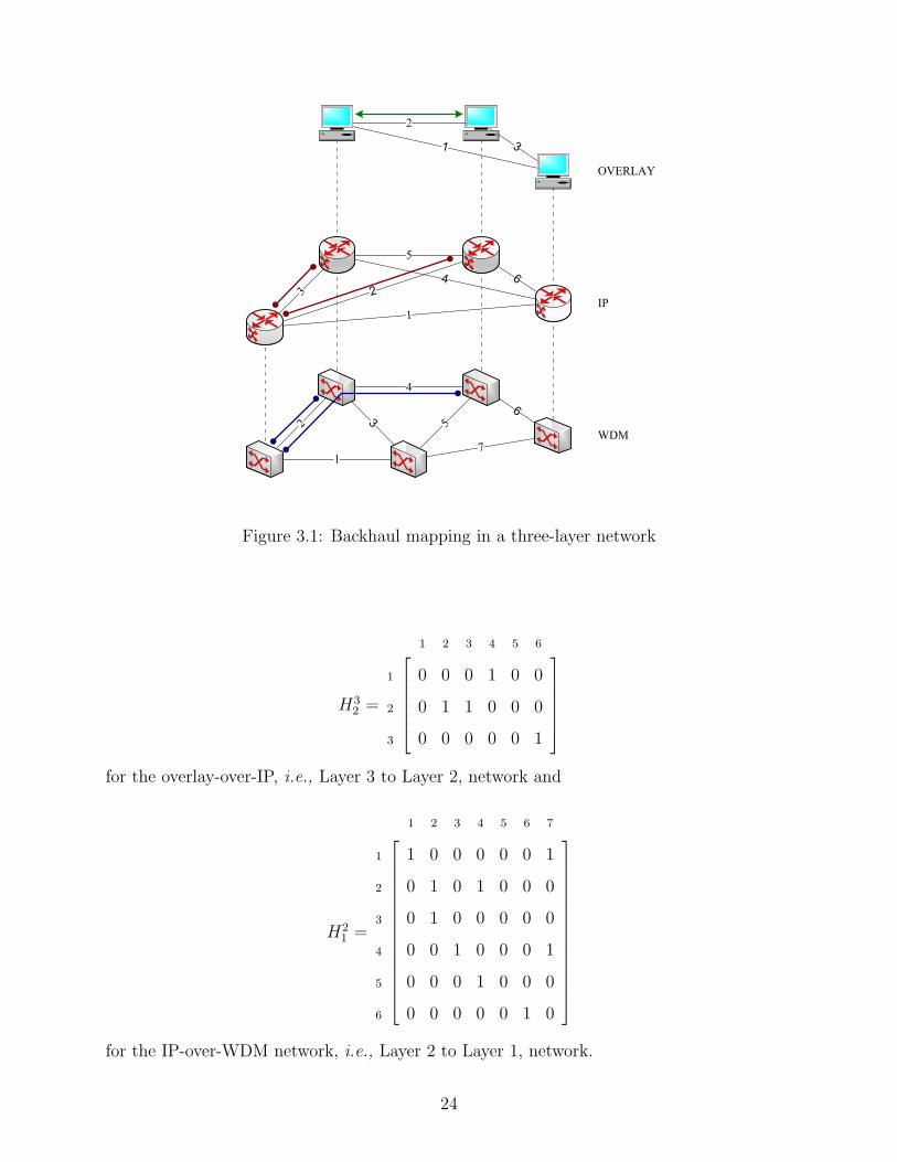
Figure 3.1: Backhaul mapping in a three-layer network
H32 =
1 2 3 4 5 6
1 0 0 0 1 0 0
2 0 1 1 0 0 0
3 0 0 0 0 0 1
for the overlay-over-IP, i.e., Layer 3 to Layer 2, network and
H21 =
1 2 3 4 5 6 7
1 1 0 0 0 0 0 1
2 0 1 0 1 0 0 0
3 0 1 0 0 0 0 0
4 0 0 1 0 0 0 1
5 0 0 0 1 0 0 0
6 0 0 0 0 0 1 0
for the IP-over-WDM network, i.e., Layer 2 to Layer 1, network.
24
While this routing is survivable, it may not also be resource-efficient or loop-free. Con-
sider link 2 at the overlay layer. This link is routed on links 2 and 3 at the IP layer. However,
because these IP links 2 and 3 use links 2 and 4, and 2 at the WDM layer, respectively, the
WDM link 2 is used twice. Thus, the solution reference [8] proposes to ensure survivability
as well as other solutions in the current literature can be resource inefficient as backhaul can
occur. In this dissertation work, we propose a survivable mapping that is backhaul-free.
3.1.1.2 Network Node Mapping In a more general case, node locations can also be
planned. Nodes could be placed in such a way that all traffic requirements can be satisfied.
Again, constraints at a node may be due to node resources such as the number of ports
or computational capabilities of an IP router or an optical switch. In this case, let a node
mapping from N j to N i, denoted Kji , be a rule associating each element nj of N j with a
corresponding element ni of N i. We consider a node mapping such that: (1) for every node
nj ∈ N j, there is exactly one node ni ∈ N i such that the relationship between these two
nodes is defined (unsplittable node) and (2) not all ni ∈ N i may be included in the node
mapping.
In general cases, restrictions on the unsplittability conditions could be relaxed, thereby
allowing two or more lower layer paths to support one upper layer link or two or more lower
layer nodes to support one upper layer node e.g., load sharing for a node.
3.2 BACKHAUL ROUTING
3.2.1 Traffic Layer
Traffic may be present in one or more layers of the network graph. Unlike other work in this
area where traffic and network layers are considered as one layer, we explicitly consider them
as two separate layers and present the backhaul routing problem. If this problem occures,
the overlay topology may need to be redesigned if traffic in the overlay network changes
dynamically or in a way that affects the optimality of the static design.
25

Figure 3.2: Backhaul example in a three-layer network
3.2.1.1 Direct/Primary Traffic Flow Routing In accordance with initial traffic re-
quests, the original overlay topology is usually constructed such that primary traffic flow is
supported by a direct path. Therefore, it is a one-to-one correspondence (bijective) mapping
from overlay traffic layer to overlay network layer.
3.2.1.2 Indirect/Backup Traffic Flow Routing When an overlay topology has be-
come disconnected due to failures, traffic reroutes through its backup path. A backup path
typically needs one or more intermediary nodes for failed traffic to be rerouted through.
This path is often called an indirect path and may be subject to the backhaul problem if the
mapping is not properly designed.
In order to adequately contextualize this notion, we illustrate how the two paths, primary
and backup, are distinctly defined. Consider the network example in Figure 3.2 where
blue (darkest) and purple (lightest) lines constitute an indirect (backup) path and a brown
(dark) line represents a direct (primary) path. Paths in different layers are differentiated
through three different line-ends, namely arrow, circle, and square for overlay, IP, and WDM
layers, respectively. Here, an indirect overlay path A-B-D is used as a backup after direct
26

primary path A-D fails, which is a typical path protection scheme in the overlay network.
However, a backhaul routing loop occurs at link B-E in the physical WDM layer, which is an
undesirable property that is not directly addressed in [12] or any other existing literature.
This backhaul problem may arise in a general case when an indirect backup path routes
through an intermediary node [46], which is B in this case. In [12], only direct paths are
explicitly considered; however, both direct and indirect paths are fully examined in this
dissertation. Therefore, overlay link mapping alone is not sufficient when backup paths or
any paths requiring more than a single hop are considered.
In this dissertation, we directly address the backhaul mapping and routing problems in
the explicit pursuit of survivability in the context of overlay-IP-WDM networks.
3.3 SUMMARY
This chapter gives an overview of the problems under consideration and defines the sur-
vivability of a layered network in the context of network and traffic layers of the network.
The next four chapters document our contributions, our perspectives, and major numerical
results and findings.
27

4.0 CROSSLAYER SURVIVABLE MAPPING
4.1 INTRODUCTION
The lack of a well-studied survivability framework for a network of three layers or more
has motivated our design of crosslayer survivable mapping as an initial look at layered
networks. In some networks [47], overlay layer applications are believed to consume as much
as 75 percent of the bandwidth of IP-over-WDM core backbone network infrastructures
even though they make up only 5 percent of the users. This chapter focuses on link mapping
in multilayer networks, including the interactions between and among layers and proposes
an efficient survivable mapping when all layers are considered concurrently. Section 4.2
provides an overview of the design challenges. Section 4.3 defines the problem and proposes
a mathematical model to provide minimum joint primary-backup capacity allocation for
survivability of the traffic that originates at every network layer. Evaluation results and
analysis are provided in Section 4.4. An example of the crosslayer mapping design for ring
overlays is given in Section 4.5. Finally, our summary is given in Section 4.6.
4.2 MOTIVATION
The existing literature on survivable mapping, which is also known as survivable routing or
survivable logical topology planning either explicitly considers a two-layer topology such as
IP-over-WDM or deals with a logical topology constrained within a physical network such as
WDM lightpaths in an optical fiber cable [8]. However, overlay networks are receiving more
attention not only because they can offer new services, but also because they can overcome
28

functionality limitations of the Internet without the need for modifications of the underlying
network layers. Therefore, it is important that this overlay network layer also be included
in the network design to complete the whole picture.
4.3 PROBLEM STATEMENT
In this chapter, we consider the survivability problem in three-layer networks such that no
backhaul occurs and survivability is implemented using SBPP (please refer to Section 2.3.2
in Chapter 2 for the definition) under single-link failures.
4.3.1 Notation Used
The notation adopted in this chapter can be summarized as follows:
l Network layer index, where l = 1, 2, 3 refers successively to higher layers,
i.e., the WDM, IP, and overlay layers, respectively
N l l -th layer node set
Ll l -th layer link set
F l l -th layer flow vector
M l Diagonal matrix of bandwidth of l -th layer flow index f l with dimension |F l| × |F l|
M lc Diagonal matrix of bandwidth of l -th layer flow index f l with dimension |F l| × |F l|,
when mapped to layer l − 1
Bl l -th layer incidence matrix with dimension |N l| × |Ll|
Blc l -th layer incidence matrix with dimension |N l−1| × |Ll−1|,
when mapped to layer l − 1
Dl l -th layer flow-node incidence matrix with dimension |F l| × |N l|
Dlc l -th layer flow-node incidence matrix with dimension |F l| × |N l−1|,
when mapped to layer l − 1
P l l -th layer primary path matrix with dimension |F l| × |Ll|
29

P lc l -th layer primary path matrix with dimension |F l| × |Ll−1|,
when mapped to layer l − 1
Ql l -th layer backup path matrix with dimension |F l| × |Ll|
Qlc l -th layer backup path matrix with dimension |F l| × |Ll−1|,
when mapped to layer l − 1
W l l -th layer primary-path link capacity vector with dimension |Ll| × 1
Gl l -th layer spare capacity matrix with dimension |Ll| × |Ll|
Glc l -th layer spare capacity matrix with dimension |Ll−1| × |Ll−1|,
when mapped to layer l − 1
Sl l -th layer backup-path link capacity vector with dimension |Ll| × 1
Slc l -th layer backup-path link capacity vector with dimension |Ll−1| × 1,
when mapped to layer l − 1
I Identity matrix
Hji Survivable mapping matrix between layers j and i (H1
0 = I)
e The column vector of all ones in Rn
(.)c The sucscript c stands for crosslayer by means of mapping or cost of the lower-layer
link use
In particular, we consider the following mapping specific to the IP-over-WDM network
in our considered three-layer networks.
B2c = B2 (4.1)
D2c = [D2|0] (4.2)
P 2c = P 2H2
1 (4.3)
M2c = M2 (4.4)
Because the incidence matrix is topology dependent, a layer 2 incidence matrix, when
mapped to layer 1, is equivalent to that of layer 1. This is shown in equation (4.1) by the
subscript c denoting crosslayer. Since a layer 2 network may not have the same number of
nodes as the layer 1, i.e., it could be more than or equal to that in layer 1 network, the
flow-node incidence matrix in (4.2) is mapped to layer 1 by padding columns of zeros as
30

necessary to D2. Equation (4.3) computes the primary paths of layer 2 from the perspective
of layer 1 given as P 2c using the link-mapping information in H2
1 . In (4.4), the bandwidth of
the mapped layer 2 flow still holds the same value as that of layer 2 flow as it depends on
flows only. We also note that the mapped layer 2 flow may include additional information
such as grooming or framing overhead; however, these have not been considered in this work.
The motivation behind these equations is briefly discussed in the next section; the details
are given later in Chapter 7.
4.3.2 An Optimization-based Formulation
Layer l topology of an uncapacitated network consists of a set of nodes N l and a set of
directional links Ll, each two of which are equivalent to two unidirectional links with an
equal number of wavelengths, i.e., same capacity, and the same failure state, i.e., available
or failed, in each link and have opposite direction. Then the incidence matrix Bl [48] of the
network which has a row for each node and a column for each link where Bl(n, e) = 1 if and
only if link e is connected to source node n and −1 if n is a sink node can be obtained.
Traffic originating at layer l can be formulated as follows: Let Dl denote a flow-node
incidence matrix at layer l in which each row represents a source-sink pair of a flow index
f l where 1 ≤ f l ≤ |F l| and F l is a vector of flow at layer l. The matrix Dl has +1 in
the row corresponding to a traffic source and −1 in the row corresponding to a traffic sink.
Flow bandwidth is assumed integral based on a fixed bandwidth unit and is represented by
ml(f l) for each flow index f l. The bandwidth matrix M l puts ml(f l) on the main diagonal;
therefore, this matrix is a diagonal matrix with dimension |F l| by |F l|. Identical source-sink
pairs are here regarded as a single flow equivalent to the sum of all the flow bandwidths
combined.
We aim at providing survivability using the SBPP scheme at layer l. Let P l be the
primary path matrix with dimension |F l| by |Ll|. For the element plfe of P l, plfe = 1 if link e
is in the primary path of flow index f l, and 0 otherwise. Likewise, the backup path matrix
Ql with the same dimension as the primary path can be defined in a similar manner.
In order to route a link in layer l+1 on layer l properly, a good link mapping such that
31

layer l+1 topology remains connected even after a single link failure in layer l is required.
Such a mapping is given in [8] and is formulated as a mathematical optimization model
in [49]. However, an additional requirement is needed in networks consisting of three layers
or more to prevent backhaul. This requirement is given as follows:
Definition 4.1. The condition CL of the link mapping in three-layer networks such that no
backhaul routing occurs is defined by H32H
21 � 1, where the � symbol denotes element-wise
comparison, i.e., each element of the product matrix is no more than 1.
The following Lemma is motivated by the condition CL.
Lemma 4.1 (Crosslayer Mapping). No backhaul mapping occurs in a three-layer network if
and only if a link mapping satisfies the condition CL.
Proof. Given two survivable mappings, H32 and H2
1 , in a three-layer network, it can be
followed that an element (i, j) of the matrix product H32H
21 is nonzero if and only if a layer
1 link j is used by a layer 3 link i. This element determines the number of times layer 1 link
j is used by layer 3 link i. Because in no backhaul routing there should be exactly one such
use by any path in layer 3; therefore, the condition CL : H32H
21 � 1 is required in routing
with no backhaul.
Clearly, the proof of Lemma 4.1 constructs efficient or backhaul-free mapping in three-
layer networks. Next, we show that the situation is much more favorable when survivability
is also considered.
Theorem 4.1 (Crosslayer Survivable Mapping). A mapping is survivable and produces no
backhaul if and only if its corresponding link mapping is two-connected and satisfies the
condition CL.
Proof. Necessity and Sufficiency are a direct result of [8, Theorem 1] and Lemma 4.1 previ-
ously given.
In addition, it can also be seen that the mapping can withstand multiple link failures if
proper survivable mapping [9], [50] is employed.
32

The formulation of the Overlay-over-IP-over-WDM survivable networks employing SBPP
can be summarized in a mathematical optimization model as follows: Denote l = 1, 2, 3 as
the WDM, IP, and Overlay layer, respectively; this alpha numeric notation may be used
interchangeably in this section as well as throughout the dissertation. The joint capacity
allocation (JCA) problem in three-layer networks (JCA3L) can be formulated as follows:
Objective:
minP l,Ql
∑
l={1,2,3}W lT (
l∏
k=1
H l−k+1l−k ) e +
∑
l={1,3}SlTe +
∑
l={2}Sl
T
c e, (4.5)
subject to:
Primary Paths:
P lBlT = Dl, l ∈ {1, 2, 3}, (4.6)
W l = (M lP l)Te, l ∈ {1, 2, 3}, (4.7)
W l ∈ R|Ll|, l ∈ {1, 2, 3}, (4.8)
P l : binary matrix, l ∈ {1, 2, 3}. (4.9)
Backup Paths:
QlBlT = Dl, l ∈ {1, 3}, (4.10)
QlcB
lc
T= Dl
c, l ∈ {2}, (4.11)
Ql : binary matrix, l ∈ {1, 3}, (4.12)
Qlc : binary matrix, l ∈ {2}. (4.13)
33
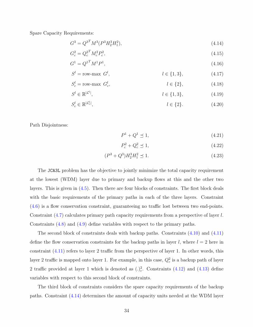
Spare Capacity Requirements:
G3 = Q3TM3(P 3H32H
21 ), (4.14)
G2c = Q2
cTM2
c P2c , (4.15)
G1 = Q1TM1P 1, (4.16)
Sl = row-max Gl, l ∈ {1, 3}, (4.17)
Slc = row-max Glc, l ∈ {2}, (4.18)
Sl ∈ R|Ll|, l ∈ {1, 3}, (4.19)
Slc ∈ R|Llc|, l ∈ {2}. (4.20)
Path Disjointness:
P 1 +Q1 � 1, (4.21)
P 2c +Q2
c � 1, (4.22)
(P 3 +Q3)H32H
21 � 1. (4.23)
The JCA3L problem has the objective to jointly minimize the total capacity requirement
at the lowest (WDM) layer due to primary and backup flows at this and the other two
layers. This is given in (4.5). Then there are four blocks of constraints. The first block deals
with the basic requirements of the primary paths in each of the three layers. Constraint
(4.6) is a flow conservation constraint, guaranteeing no traffic lost between two end-points.
Constraint (4.7) calculates primary path capacity requirements from a perspective of layer l.
Constraints (4.8) and (4.9) define variables with respect to the primary paths.
The second block of constraints deals with backup paths. Constraints (4.10) and (4.11)
define the flow conservation constraints for the backup paths in layer l, where l = 2 here in
constraint (4.11) refers to layer 2 traffic from the perspective of layer 1. In other words, this
layer 2 traffic is mapped onto layer 1. For example, in this case, Q2c is a backup path of layer
2 traffic provided at layer 1 which is denoted as (.)2c . Constraints (4.12) and (4.13) define
variables with respect to this second block of constraints.
The third block of constraints considers the spare capacity requirements of the backup
paths. Constraint (4.14) determines the amount of capacity units needed at the WDM layer
34

in order to protect the primary overlay paths P 3 upon their failures. The last component
in this constraint translates the capacity requirement to the view of the WDM layer using
crosslayer mappings that conform with Theorem 4.1. At the IP layer, the situation is a
little different. This is because while primary paths are calculated at this layer, the backup
paths are provided at the WDM layer. We chose this survivability strategy for IP traffic by
means of the best strategy as studied in Chapter 7 and [51]. Since traffic at the WDM layer
is also provided backup paths at the WDM layer, this requires no translation. Therefore,
whether traffic originates at the IP or the WDM layer, the amount of capacity units can
be determined by constraints (4.15) and (4.16), respectively. The row-max (.) operation in
(4.17) and (4.18) determines the maximum element in each row of the matrix Gl. These
elements reflect the amount of capacity needed by their corresponding link in order to protect
against a single link failure at the WDM layer. Like previously given, constraints (4.19) and
(4.20) define a variable with respect to spare capacity of the backup paths. These spare
capacity matrices are not allowed to share across layers; however, the capacity can be shared
within a layer. It should be noted that mapping is not considered in the optimization of the
backup-path link capacity vectors in objective (4.5) because we have already included the
mapping in constraints (4.14) and (4.15), and equation (4.3) which is reflected in constraints
(4.17) and (4.18).
The relationship between the primary and backup paths are provided in the fourth block
of constraints. Constraint (4.21) guarantees that, at layer 1, each backup path is disjoint
from the primary path. Constraint (4.22) guarantees paths disjointness of layer 2 traffic at
layer 1. As the backup path to layer 2 traffic flows is provided at layer 1, this constraint
guarantees such disjointness between this backup path and the mapped primary path. At
layer 3, both primary and backup paths are computed at this layer; however, because the
overlay network has no knowledge of the underlying layers, they are not necessarily disjoint
from the perspective of layer 1. Constraint (4.23) guarantees such disjointness at layer 1. The
JCA3L problem is NP-hard as it can be reduced from some known NP-hard problems [8],
[45].
Before moving to the next section, which analyzes a large network, we have verified the
optimization formulation manually on some small networks against the results obtained from
35

an AMPL/CPLEX implementation to ensure its correctness.
4.4 NUMERICAL RESULTS AND ANALYSIS
In this section, we evaluate the efficiency and effectiveness of the crosslayer survivable map-
ping (CSM) in three-layer networks, we consider the NSFNet consisting of 14 nodes, 21 links,
depicted in Figure 4.1, as a layer 1 (WDM) network. In the case of layer 2 (IP) network,
links are added to the NSFNet such that the network is fully connected. Layer 3 (overlay)
network is constructed as a partial, i.e., half, mesh of the full mesh layer 2 topology, as
shown in Figure 4.2. The overlay network is partially-connected. Here, the maximum num-
ber of overlay traffic flows in where each flow request is represented by an overlay link is 46.
These particular links are employed as a means to overcome crosslayer survivable mapping
limitation in this topology that not all disjoint paths in the overlay layer are also disjoint at
the WDM layer. It should be noted here that the considered single-link flows can easily be
extended into the case when the flows require two or more overlay links by concatenating
the links. In addition, we consider a number of demand flows at the overlay layer and a fixed
number of demand flows at the IP and WDM layer; the numbers of IP and WDM traffic
flows do not affect capacity requirements of the overlay since sharing spare capacity across
layers is not allowed. Following the setting of a three-layer network, we present some results,
provide discussions, and evaluate the performance of crosslayer survivable mapping against
three other mappings in terms of capacity overbuilding, flow overrouting, and link overusing
due to both primary and backup paths.
To show efficiency and effectiveness of CSM, which conforms to Theorem 4.1. We first
obtain CSM: (H21 , H
32 ). Then for comparison purpose, we also compute three other mappings,
M1: (H21 , H
32 ), M2: (H2
1 , H32 ), and M3: (H2
1 , H32 ). By using the integer linear programming
(ILP) formulation of [8], we can calculate the two mapping matrices H32 and H2
1 , each of
which corresponds to the link mapping matrix of the overlay-over-IP and the IP-over-WDM
networks, respectively. In this calculation, each mapping matrix is obtained independently
without considering the effect from the other network layer. That is, H21 is computed as if
36

3
1 4
2
11
5
6
108
7
129
14
13
CA 1
CA 2
WA
UT
CO
TX GA
MD
PAIL
NE
NJ
NYMI
Figure 4.1: The 14-node, 21-link NSFNet
3
1 4
2
11
5
6
108
7
129
14
13
CA 1
CA 2
WA
UT
CO
TX GA
MD
PAIL
NE
NJ
NYMI
Figure 4.2: The 14-node, 46-link overlay network
the network had only two layers – IP and WDM. Similarly, H32 is obtained from the two
layers 3 and 2 – overlay and IP. Therefore, CSM, M1, M2, and M3 are simply combinations
of the four possible mapping matrices H21 , H3
2 , H21 , and H3
2 .
37

0 5 10 15 20 25 30 35 40 45 500
10
20
30
40
50
60
70
80
90
100
Number of overlay traffic flows
Cap
acity
ove
rbui
ldin
g (C
O)
�� � �� ���� � � �� � � ���� � � � � � ���� � � �� � � ���� � �
Figure 4.3: Capacity overbuilding of the overlay network
4.4.1 Metric 1: Capacity Overbuilding
Capacity overbuilding (CO), the percentage of the excess capacity requirement of the overlay
traffic due to backhaul routing, is here used to evaluate the efficiency of the proposed CSM.
The excess capacity occurs at the WDM layer whenever WDM links are unnecessarily used
by overlay primary path, overlay backup path, or both. It should also be noted that CO is
not the same as resource overbuilding (RO) [52], which refers to a capacity ratio of backup
paths to primary paths.
Figure 4.3 shows CO under various network loads that our proposed CSM can effectively
eliminate the redundant capacity reservation. This is because it takes into account all three
layers together by addressing the problem of backhaul routing. In here, the CSM has best
CO partly because the designs of the two mappings – Layers 3 and 2, and Layers 2 and 1 –
in all M1, M2, and M3 are carried out independently.
38

In addition, both M1 and M2 have better CO than M3 because the alteration, discussed
previously, has shown little change from the original mappings. This is partly due to the two-
layer topology that has a limit on the number of mapping choices that a top-layer network
has to be survivable under a single link failure at the lower layer. This limitation also happens
in any two-layer network, but in the case of M1 versus M2 the situation is different. Their
COs are dependent on topology, mapping, and order of flows. In this particular network
M2 is outperformed by M1, in part for the two mapping matrices of the three-layer network
and partly because full-mesh characteristics in Layer 2 (IP) network is said to provide much
deviation in H32 from H3
2 in terms of element-wise comparison of the two matrices. The COs
of the four schemes become increasingly different under a higher number of overlay traffic
flows because backhaul routes occur more often.
4.4.2 Metric 2: Flow Overrouting
Defined as the ratio of the number of overlay traffic flows that are routed on one or more
backhaul links at the WDM layer to the total number of overlay flows, flow overrouting (FO)
or fraction of backhaul flows is used to show the number of overlay flows that are affected
by backhaul routing. In a manner similar to CO, Figure 4.4 shows that CSM can solve the
problem while some flows in M1, M2, or M3 still suffer from it. In all M’s, the flat FO
at the beginning is understood to coincide with the flows ordering in our studied network;
however, the average number of the affected flows is steady as the number of overlay traffic
flows is increasing. In particular when the number of flows is 11 or fewer, M1 has no flow
over routed, i.e., 0% FO. This corresponds to its CO in Figure 4.3 where M1 also has no
capacity overbuilt when there are 11 flows or fewer. In contrast to M1, M2 has a 100% FO
when there are 15 flows or fewer. This is because either or both of the primary and backup
paths are overrouted. This observation of the FO again corresponds to the CO in Figure 4.3
but with a different degree when the number of flows varies between 1 to 15.
39
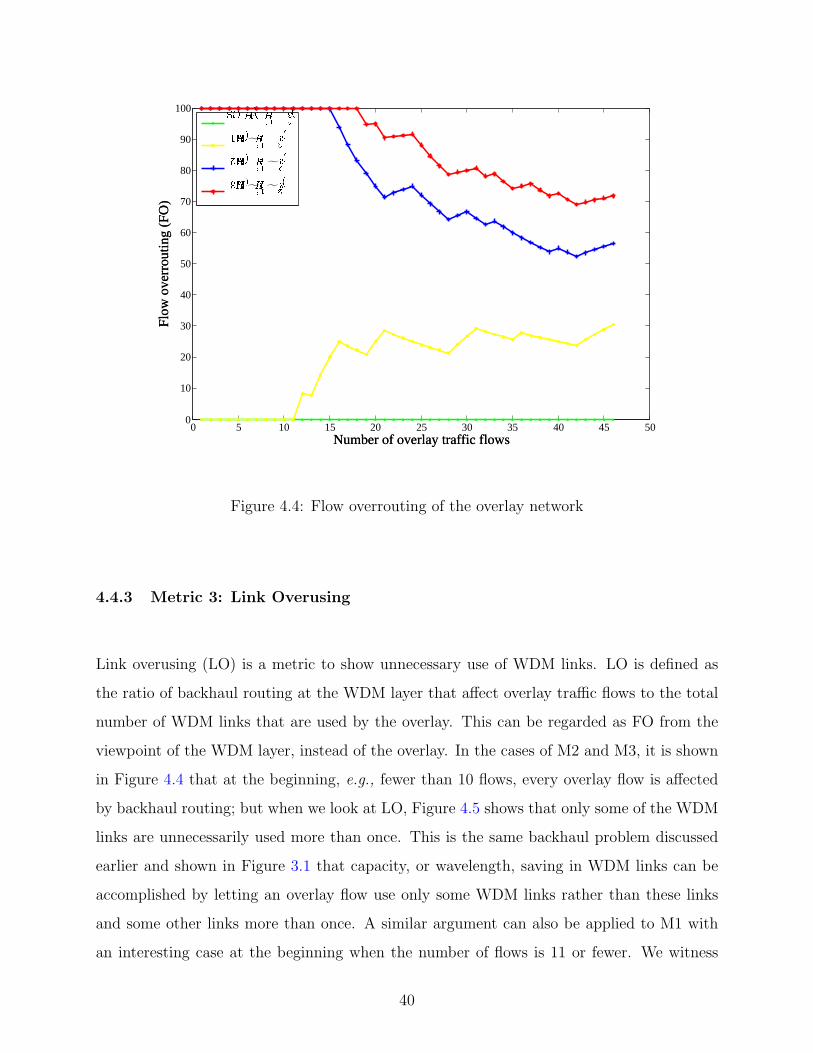
0 5 10 15 20 25 30 35 40 45 500
10
20
30
40
50
60
70
80
90
100
Number of overlay traffic flows
Flow
ove
rrou
ting
(FO
)
�� � �� ���� � � �� � � ���� � � � � � ���� � � �� � � ���� � �
Figure 4.4: Flow overrouting of the overlay network
4.4.3 Metric 3: Link Overusing
Link overusing (LO) is a metric to show unnecessary use of WDM links. LO is defined as
the ratio of backhaul routing at the WDM layer that affect overlay traffic flows to the total
number of WDM links that are used by the overlay. This can be regarded as FO from the
viewpoint of the WDM layer, instead of the overlay. In the cases of M2 and M3, it is shown
in Figure 4.4 that at the beginning, e.g., fewer than 10 flows, every overlay flow is affected
by backhaul routing; but when we look at LO, Figure 4.5 shows that only some of the WDM
links are unnecessarily used more than once. This is the same backhaul problem discussed
earlier and shown in Figure 3.1 that capacity, or wavelength, saving in WDM links can be
accomplished by letting an overlay flow use only some WDM links rather than these links
and some other links more than once. A similar argument can also be applied to M1 with
an interesting case at the beginning when the number of flows is 11 or fewer. We witness
40

0 5 10 15 20 25 30 35 40 45 500
10
20
30
40
50
60
70
80
90
100
Number of overlay traffic flows
Lin
k ov
erus
ing
(LO
)
�� � �� ���� � � �� � � ���� � � � � � ���� � � �� � � ���� � �
Figure 4.5: Link overusing of the overlay network
a unanimous correspondence among the LO, FO, and CO here in the sample network that
backhaul routing does not occur for the first 11 flows in the case of M1; therefore, no capacity
is overbuilt.
4.5 CASE STUDY: RING OVERLAY NETWORK
In this section, we evaluate the extent of the backhaul problem and the efficiency of CSM
on a ring-type overlay. To evaluate the performance of CSM, we consider three-node ring
overlay networks, where each overlay is chosen from(
143
)= 364 possible rings. An overlay
is constructed on top of the IP-over-WDM network similar to the one considered in Section
4.4, which is based the network in Figure 4.1. Only overlays that do not see backhaul
happens when CSM is deployed are considered; the number of overlays that corresponds to
41

0 10 20 30 40 50 60 70 80 90 100 110 120 130 140 150 160 170 180 190 200 210 2200123456789
1011121314151617181920
Number of ring overlays
Capa
city
ove
rbui
ldin
g (C
O)
CSM(H 2
1 , H 32 )
M1(H 21, H 3
2 )M2(H 2
1 , H 32)
M3(H 21, H 3
2)
Figure 4.6: Capacity overbuilding of the ring overlays
this condition is 229.
As previously defined, the three metrics: CO, FO, and LO, are used to evaluate the
performance of CSM against the three other mappings. In addition, resource overbuilding
(RO) or redundancy, which is a ratio of backup path capacity to the primary path capacity,
is also considered. Here the simulation is run 10 times and overlays are randomly chosen
each time. We also observe that all plots tend to be stable, almost no fluctuation, beyond
this number of simulation runs.
Figure 4.6 shows that in CSM, zero CO results. This corresponds to the previous findings
and analysis. The remaining three mappings show some variation because of different net-
work settings; however, the trends still continue. We observe in this figure that M3 performs
worst most of the time, and M1 and M2 are competing during the first half of the maximum
42

0 10 20 30 40 50 60 70 80 90 100 110 120 130 140 150 160 170 180 190 200 210 2200123456789
1011121314151617181920
Number of ring overlays
Flow
ove
rrout
ing
(FO
)
CSM(H 2
1 , H 32 )
M1(H 21, H 3
2 )M2(H 2
1 , H 32)
M3(H 21, H 3
2)
Figure 4.7: Flow overrouting of the ring overlays
number of rings whereas M1 tends to outperform towards the end.
The results are more predictable in the cases of FO and LO, which are shown in Figure 4.7
and Figure 4.8, respectively. Having flat FO and LO at zero, CSM behaves as expected. For
the remaining three other mappings, both FO and LO increase as the number of overlay
rings grow. The difference is more noticable in M3 when both of the two mapping matrices
are altered. Comparing M1 and M2, M2 mostly performs better. The M2 performance is
dependent on the two mapping matrices, which might happen to better suit the ring overlays
than M1.
In addition, we also investigate on the performance of RO in all four mapping schemes.
In Figure 4.9, we show that RO decreases as the number of ring overlays increases. This is
predictable because spare capacity that is already dimensioned is likely to as well support
43

0 10 20 30 40 50 60 70 80 90 100 110 120 130 140 150 160 170 180 190 200 210 2200123456789
1011121314151617181920
Number of ring overlays
Link
ove
rusin
g (L
O)
CSM(H 2
1 , H 32 )
M1(H 21, H 3
2 )M2(H 2
1 , H 32)
M3(H 21, H 3
2)
Figure 4.8: Link overusing of the ring overlays
the capacity need of other flows. It is also noteworthy that RO is always greater than unity
here. This could be because each primary path always uses one link at the overlay layer
while a backup path consistently routes on two links. As a result, the backup paths are more
likely to require much more capacity when a ratio is taken and even when the capacity is
shareable.
4.6 SUMMARY
This chapter presents the concept of crosslayer survivable mapping, which considers link
mapping across all layers, introduced in this chapter is applicable to all multilayer net-
44
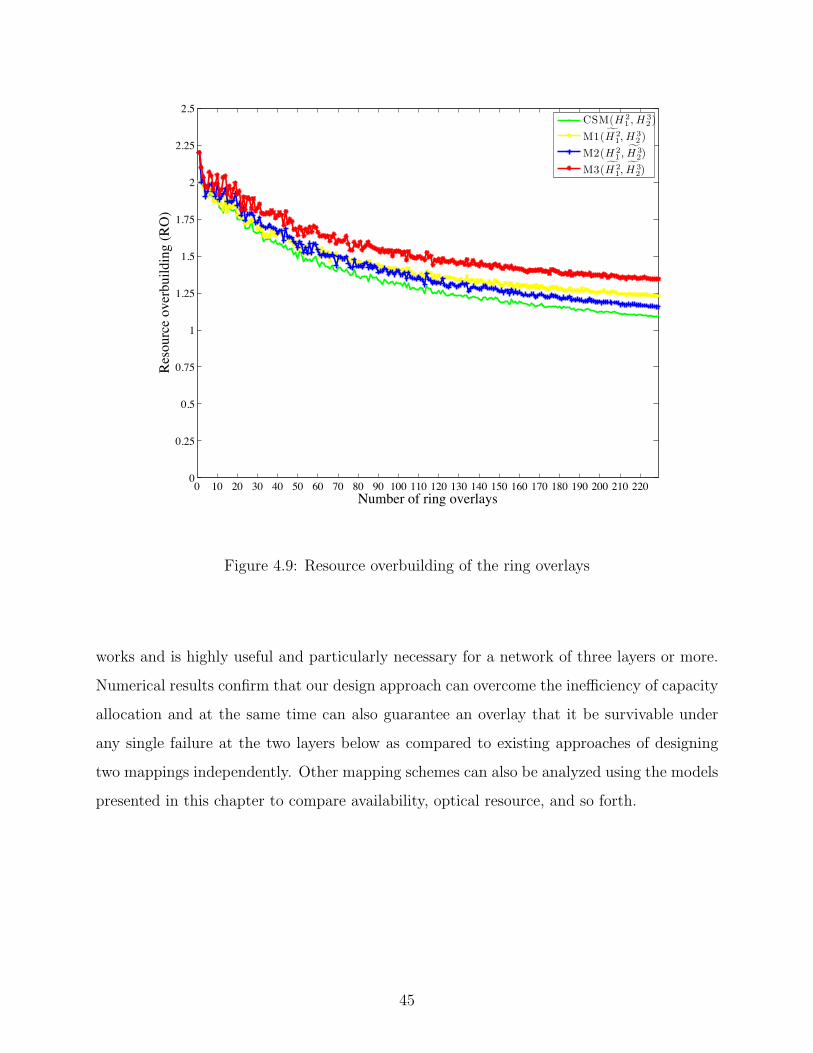
0 10 20 30 40 50 60 70 80 90 100 110 120 130 140 150 160 170 180 190 200 210 2200
0.25
0.5
0.75
1
1.25
1.5
1.75
2
2.25
2.5
Number of ring overlays
Reso
urce
ove
rbui
ldin
g (R
O)
CSM(H 2
1 , H 32 )
M1(H 21, H 3
2 )M2(H 2
1 , H 32)
M3(H 21, H 3
2)
Figure 4.9: Resource overbuilding of the ring overlays
works and is highly useful and particularly necessary for a network of three layers or more.
Numerical results confirm that our design approach can overcome the inefficiency of capacity
allocation and at the same time can also guarantee an overlay that it be survivable under
any single failure at the two layers below as compared to existing approaches of designing
two mappings independently. Other mapping schemes can also be analyzed using the models
presented in this chapter to compare availability, optical resource, and so forth.
45
5.0 DIFFERENTIATED CROSSLAYER NETWORK MAPPING
5.1 INTRODUCTION
Layered architecture constitutes one of the most fundamental structures of communications
network design. This layering approach sees modern networks as being composed of overlay,
IP, and WDM network layers with an emphasis on service, data forwarding, and bandwidth,
respectively. With increasing needs, overlays provide a layer for the network which can take
a role of processing and passing data between end-systems that arise to serve a range of
diverse purposes and needs [41], [53], [54].
One of the principal areas of concern in overlay communications is service disruption.
This, in part, occurs as a result of communications outages after failures or attacks. Rec-
ognizing common threats from electromagnetic pulse attacks (EMP) [55], earthquakes, or
floods, to dragging anchors or shared failure risks, network infrastructure is a critical part of
vulnerability mitigation to these threats. One way to avoid such a failure or human-based
attack is to hide parts of the network information from unclassified or certain customers, e.g.,
customers could see a network with different node degrees. Customers can be ranked based
on their relationship with the network provider upon an established contract or procurement
record. Alternatively, network information can be more open in some situations: Consider
an ideal business model, in which a business is solely motivated by revenue generation. It is
also important to recognize that in some cases, network information can be more open. In
this case, service differentiation could be offered to customers according to their willingness
to pay the price for a particular service. For example, customers with a limited budget might
be more willing to tolerate a higher level of service disruption.
To meet these challenges, a number of studies have recognized the impact of underlay
46

topology on the overlay topology [40], [56], [57], [58], [59], [60]. However, little attention has
been paid to the problem of duplicate physical links that are shared by a virtual link [40], [58]
in a multilayer network architecture.
In this chapter, we consider the problem of designing a differentiated communications
network that is both efficient and survivable in the explicit context of overlay-IP-WDM. We
consider the problem of link and flow path mapping in the entire three-layer network that
avoids link duplication or backhaul at the WDM layer and at the same time be survivable
under a single-link failure. We show that the introduction of forbidden link matrix is sufficient
for differentiated network mapping and yet the proposed matrix is peculiar to the problem
we are exploring.
The remainder of this chapter is organized as follows: In Section 5.2, we discuss prior
related work as background for our discussion in this chapter. Then we describe the problem
and formulate it as an integer linear programming (ILP) in Section 5.3. Next in Section 5.4,
we present our analysis and provide some numerical results. Finally, we summarize the
chapter in Section 5.5.
5.2 BACKGROUND
Nearly all existing literature focuses on topology use from service resilience or traffic engi-
neering points of view. This section aims at providing background on the work from each of
the two sub-layers in the layered network architecture.
5.2.1 Use of Topology Knowledge in Overlay Networks
At the overlay network layer, some initial effort has been made to examine the impact of
underlying topology on the failure recovery ratio of overlay services [61]; unfortunately, how
the link mapping was done is not fully explained in this work. A number of topology con-
structions of the overlay over a single physical network have been investigated; unfortunately,
how the link mapping was done is not fully explained in this work. An effort that aims at
47

building a generic overlay is SON [62]. A service overlay network (SON) can directly pur-
chase bandwidth with a service guarantee from IP layer Internet service providers (ISPs)
to build a logical end-to-end service overlay; end users can buy the service with some value
added as provided by the SON. On one hand, by acting as a service broker, SON provides
service guarantees on a much finer granularity to end customers, i.e., per flow, than an
ISP which is primarily concerned with provisioning bandwidth management on a per-SON
basis. However, on the other hand, this construction requires two contracts: Users-SON
and SON-ISPs. In addition, failure guarantee is not considered a part of the service guar-
antee in SON. Another similar effort that aims at offering Internet QoS using overlays is
OverQoS [63]. OverQoS uses a controlled loss virtual link (CLVL) to provide a bound on
the loss rate experienced by an aggregate traffic flow. This service option can be provided
to customers without penalizing the existing best-effort background traffic. However, this
work does not consider a subscription of dedicated bandwidth or failure guarantee as a part
of QoS. QoSMap [46] aims at increasing resiliency against QoS failures while meeting QoS
requirements of an overlay application. A backup path is provided for the resiliency and
the considered QoS is based on the number of hops, e.g., latency, loss rate. However, only
heuristic solutions are sought. Another work aimed at provisioning end-to-end QoS across
multiple autonomous systems (ASes) is presented in [60]. Here the authors formulate a net-
work topology design problem for a service overlay network with bandwidth guarantees as
a variant of the assignment problem. By connecting each end system to a provider node
through an ISP at minimum cost, the problem can be divided into two sub-problems: end
system-provider node and provider node-provider node. They show that, in a special case,
this problem can be simplified and, thus is tractable. The same setting is further examined
in a number of cases in [64]. Yet, an argument of offering QoS at the overlay is interestingly
made in [65].
A key challenge in constructing a resilient overlay is to provide good routing services
while maintaining QoS when failures happen. A heuristic-based is presented in [58]. Here
the authors proposes a construction of a distributed overlay service using only passive mea-
surements and static topology information of the underlay from PlanetLab [66]. A variant
of the link-pruning algorithm is investigated on a sparse overlay, e.g., a few hundred nodes.
48

Like RON, this approach may not scale well in a larger network. This is because the number
of overlay links in the routing mesh is a limiting factor in the scalability of the overlay as it
increases a chance of finding path duplication in the underlay network.
In fact, in order to better support overlay routing, some connectivity information at the
underlay, e.g., the IP routing table, needs to be exported to the overlay layer [57]. The
benefit of sharing this information has also been discussed in [56], which explores several
overlay constructions over a given IP underlay. This work also notes the correlation of
failures between IP-layer links and overlay links, however, without much further insight.
Reference [59] introduces some virtual network topology control mechanisms to overcome
instability due to dynamic traffic demand. They attempt to reduce the number of virtual
network topology reconfigurations, which occur when overlay traffic changes or switches its
routes, and updates in available bandwidth of the underlay WDM layer occur.
5.2.2 Use of Topology Knowledge in IP-over-WDM Networks
A number of network models offering service differentiation have been discussed lately [67],
[68]; however, only a handful of them recognize the effects of the interaction within a layered
network. Considering traffic survivability, multi-topology routing (MTR) divides a network
into multiple logical topologies and allows one or more of them for use as a backup topology
when nodes in the primary topology fail to communicate to one another due to either node
failure or link failure or both. Here the situation is analogous to the traditional way in which a
backup path is deployed to protect each primary path. Therefore, it is conceivable that MTR
would require far fewer topology images to be maintained than a backup path scheme. This
is because each whole topology is maintained rather than individual paths; however, more
spare capacity would be required or reserved. Reference [69] conducted experiments on two
topologies of real networks and found that only two logical topologies are adequate to ensure
single-link failure survivability, thereby requiring roughly only twice the required capacity of
that of a path protection scheme. In addition, the logical topologies may share some links or
any subset of physical topology with one another. When differentiation is concerned, each
of the classes could be provided with a logical topology obtained from MTR. Together with
49

a number of logical topologies, shared risk link groups (SRLGs), or constraints on the use of
physical links, with link weights can also be taken to create a set of backup topologies when
links belonging to the same group should not be grouped to the same logical topology [70].
Alternatively, imposing some constraints on the use of physical links, e.g., same failure risk
in SRLGs, or SRLG-disjoint, can also provide a number of routing topologies for different
service classes. Work on multiple-link failure is presented in [71], [72]. However, it should
be noted that although MTR provides some sort of routing isolation, it is not equivalent to
VPN.
There is work that aims at providing frameworks for resilient services [68], [73]; for
example, the Quality of Resilience (QoR) concept in [73]. This work, although mostly
qualitative, sheds light on the need for the classification. Quantitatively, little work has
been done, and the quantitative work that does exist has focused on operational aspects like
availability or downtime rather than network differentiation point of view.
5.3 NETWORK MODEL AND PROBLEM DESCRIPTION
In this section, we present a technical description of the considered layered network and a
mathematical model. The forbidden link matrix concept to enable levels of differentiation is
also discussed. The notation used in this chapter is listed as follows:
l Network layer index, where l = 1, 2, 3 refers successively to higher layers
r Multileveled service class index
N l Layer l node set
Ll Layer l link set
F lr Layer l flow vector of level r
M lr Diagonal matrix of layer l flow f lr bandwidth requirements
with dimension |F lr| × |F lr|
Bl Layer l incidence matrix with dimension |N l| × |Ll|
Dlr Layer l flow-node incidence matrix of level r with dimension |F l| × |N l|
P lr Layer l primary path matrix of level r with dimension |F lr| × |Ll|
50

Qlr Layer l backup path matrix of level r with dimension |F lr| × |Ll|
W lr Layer l primary-path link capacity vector of level r with dimension |Ll| × 1
Glr Layer l spare capacity matrix of level r with dimension |Ll| × |Ll|
Slr Layer l backup-path link capacity vector of level r with dimension |Ll| × 1
I Identity matrix
Hji Survivable link mapping matrix between layers j and i (H1
0 = I)
FLM(r) (diagonal) Forbidden link matrix of level r with dimension |L1| × |L1|
e The column vector of all ones
(.)c The sucscript c stands for crosslayer by means of mapping or cost of
the lower-layer link use
5.3.1 Forbidden Link Matrix
Before delving into details, we illustrate some scenarios when a forbidden link matrix affects
the design. Figure 5.1 shows a three-layer network overlaid on the U.S. topology. There
are a number of overlay link mapping across layers which are survivable under a single-link
failure at the bottom WDM layer. However, this number is likely to be fewer if some WDM
links cannot be used at all. In some cases, the overlay may also lack survivability. For
example, when links originated from node 12, which might be situated near a nuclear plant,
are unknown to a customer and forbidden for use, the overlay is not survivable but it is still
connected. Another example is when a set of links are forbidden or a large-scale attack,
which its design may be dependent on geographical location of the network. In some cases,
node mapping, which is not directly considered in this chapter, may be needed.
We develop a topology-related mask in a matrix form that can be integrated into link
mapping between and among network layers when multiple differentiation levels are required.
In order to incorporate this proposed matrix into a layered network for service overlay sup-
port, we need to define two link mapping matrices: one for overlay-over-IP and one for
IP-over-WDM networks. The link mapping matrix of layer i onto layer j is specified by an
(|Li|x|Lj|)-matrix H ij = (hij), where hij = 1 if and only if link j ∈ Lj is used by link i ∈ Li.
However, we also must consider the backhaul problem presented earlier in this dissertation
in which a routing loop may occur in a network of three layers or more (see Chapter 4).
51

0
1
2
34
6 89
1110
13
12
5 7
1
11
7
0
1
2
34
6 89
1110
13
12
5 7
Figure 5.1: A use case example of forbidden link matrix in a layered network
Now let FLM(r) be the diagonal forbidden link matrix of a given level r. The diagonal entry
(i, i) is one if and only if link i is allowed for flow routing and zero when it is forbidden,
i.e., taboo. In addition, it should also be noted that in a path-based protection, where the
whole end-to-end path is calculated, backhaul routing could still occur and the link mapping
matrices for survivability under any single-link failure can be obtained from the condition
given in [74]. This, however, makes our problem one of the NP-hard types.
We illustrate the use of our forbidden link matrix in Figures 5.2(a)-(c), which relates to
the WDM network layer in Figure 3.2 given earlier in Chapter 3. Here we consider offering
three differentiation levels, i.e., r = 1, 2, 3, when no link is forbidden, link 5 is forbidden, and
52

(a) r = 1 (b) r = 2 (c) r = 3
(d) r = 1 (e) r = 2 (f) r = 3
Figure 5.2: Network and link mapping matrix H21 of multileveled service class r
links 6 and 7 are forbidden or hidden from use, respectively. Link indices for the three network
layers are given as shown in these figures and Figure 3.2, where those of the IP network are
equivalent to the overlay. The corresponding forbidden link matrices and the link mapping
matrices can be obtained as follows: FLM(1) is equivalent to I7×7, FLM(2) = FLM(1) except
FLM(2)(5, 5) = 0, and FLM(3) = FLM(1) except FLM(3)(6, 6) and FLM(3)(7, 7) =0. In all levels,
H32 = I6×6; in each level, H2
1 is given in Figures 5.2(d)-(f). Note in all levels that the overlay
services are survivable under a single-link WDM failure and no backhaul occurs in the link
mapping. For example, row 1 in Figure 5.2(d) indicates that two WDM links 2 and 4 are
used by IP link 1.
Given the link mapping matrices and the forbidden link matrix, a necessary and sufficient
condition for link mapping with no backhaul for level r is given next.
Lemma 5.1 (Differentiated Crosslayer Mapping). No backhaul mapping occurs in a three-
layer network of service class r if and only if the two link mapping matrices satisfy the
following condition (CdL): H3
2H21FLM(r) � 1, where the � symbol denotes element-wise com-
parison.
Proof. First, consider a special case when FLM(r) is equivalent to the identity matrix. Given
53
two survivable mapping matrices, H32 and H2
1 , in a three-layer network, it can follow that an
element (i, j) of the matrix product H32H
21 is nonzero if and only if a layer 1 link j is used by
a layer 3 link i. This element determines the number of times layer 1 link j is used by layer
3 link i. In backhaul-free mapping there should be exactly one such use by any link in Layer
3; therefore, the condition H32H
21FLM(r) � 1 is required. Now, it remains to show that this
lemma also holds in a general case when FLM(r) is not necessarily equivalent to the identity
matrix. Because FLM(r) is a (0, 1)-diagonal matrix, it is easy to see that H32H
21I � 1 implies
H32H
21FLM(r) � 1.
Now the following theorem says that the differentiated crosslayer mapping can also be
made survivable by adding an additional condition.
Theorem 5.1 (Differentiated Crosslayer Survivable Mapping). A mapping is survivable and
is backhaul-free in a layered network if and only if the following conditions hold:
(i) for each link mapping, no single lower layer link is shared by all upper layer links
belonging to a cut-set of the upper layer topology;
(ii) the corresponding link mapping satisfies the condition CdL of Lemma 5.1.
Proof. This follows immediately from Theorem 4.1 in Chapter 4 and Lemma 5.1.
5.3.2 Service Overlay Network
We model a service overlay network (SON) as an uncapacitated network and denote it by
G = (N l,Ll), where N l is a set of nodes and Ll is a set of links. In addition, let l = 3 here
for SON to recognize its presence at a layer 3 in our network. Here each link is equivalent
to two unidirectional links with equal capacity and the same failure state, i.e., available or
failed, in each link. Given all this information, the incidence matrix Bl [75] of a network
graph G can then be obtained.
Traffic in a SON can be modeled as follows: Let F lr = (f lr) be a vector of traffic flows of
multileveled service class r in SON. As an example, f lr(n) represents the flow index n. When
associated with the network, each traffic flow can further be put in a flow-node incidence
matrix Dlr, which provides that for each row corresponding to f lr(n), an element equal to
54

1 corresponds to a traffic source, −1 corresponds to a traffic sink, and 0 otherwise. Flow
bandwidth is non-negative and integral, which can be represented by each diagonal element
of a (|F lr|,|F lr|)-diagonal bandwidth matrix M lr.
Using the preceding network and traffic information, survivability under a single-link
failure employing a shared backup path protection (SBPP) scheme allowing the capacity of
each backup path protecting a primary path to be shared can be obtained. Let P lr be the
primary path matrix comprising a set of plfe, where plfe = 1 if link e is in the primary path
of flow f lr and 0 otherwise. Therefore, the primary path matrix has a dimension of |F lr|x|Ll|.
Similarly, the backup path matrix Qlr = (qlfe) can also be formed. While primary paths alone
can be calculated from a shortest path algorithm e.g., Dijkstra’s algorithm, mathematical
models for both of the primary and the backup paths are given later in this chapter.
As a corollary to Theorem 5.1, we extend it to include traffic constituting a path matrix,
or a path-link incidence matrix.
Corollary 5.1. If T is a path matrix, then it has no backhaul if and only if T∏lk=1H
kk−1 FLM(r)
� 1, where r is a multileveled service class index.
Proof. The order in which the path matrix appears in the condition is important to ensure
backhaul-free traffic routing. Lemma 5.1 allows us to extend it to a general case by multi-
plying a path matrix on the left hand side and when a network of k layers is considered.
In our case, the matrix T can be a primary or backup path matrix. Throughout this
chapter, and in fact the whole dissertation, we consider traffic flows with no backhaul; these
include flows of both primary and backup paths. Here, the optimization-based model for the
primary paths is presented as follows:
minP 3
r
W 3rTH3
2 H21 FLM(r)e (5.1)
P 3r B
3T = D3r (5.2)
W 3r = (M3
r P3r )Te (5.3)
P 3r : binary matrix (5.4)
W 3r ∈ R|L3| (5.5)
55
Objective (5.1) aims at minimizing the total capacity requirement of the primary paths
in the network. Constraint (5.2) and constraint (5.3) define the flow conservation constraints
and the capacity they need for each traffic flow in a multileveled service class. Equations
(5.4) and (5.5) consider variables in the model.
Considering the spare capacity allocation (SCA) problem, in order to find shared backup
paths and the capacity they need to ensure that each traffic flow be survivable under a
single-link failure, we formulate the problem in a matrix-based formulation as follows:
minQ3
r
S3rTe, (5.6)
(P 3r +Q3
r)H32H
21FLM(r) � 1 (5.7)
Q3r(B
3)T
= D3r (5.8)
G3r = Q3
rTM3
rP3rH
32H
21FLM(r) (5.9)
S3r = row-max G3
r (5.10)
Q3r : binary matrix (5.11)
S3r ∈ R|L3| (5.12)
Given the overlay traffic in the SON layer, the objective function (5.6) minimizes the
total spare capacity requirement at the physical WDM layer. The rest of the model ensures
that each backup path is properly calculated. At layer 3, both primary and backup paths
are computed at this layer; however, because the overlay network has no knowledge of
the underlying layers, they are not necessarily disjoint from the perspective of the WDM
layer. Constraint (5.7) guarantees such disjointness at the WDM layer. Constraint (5.8)
defines the flow conservation constraint for the backup paths of the overlay traffic in layer
3. The subsequent constraints deal with the spare capacity allocation of the backup paths:
Constraint (5.9) calculates the spare capacity needed to ensure that each backup path is
routable when its corresponding primary path fails as a result of a link failure at the WDM
layer, and Constraint (5.10) determines the amount of capacity units each link needs to
reserve by computing the minimum capacity that link needs when any one of the other links
may fail. This can be realized by the row-max (.) operation. These elements reflect the
amount of capacity needed by their corresponding link in order to protect against a single
56

link failure at the WDM layer. Constraint (5.11) and Constraint (5.12) define variables
associated with the preceding set of constraints.
5.3.3 Infrastructure Network
To relate an IP-over-WDM infrastructure network to the SON, we adapt the notation pre-
viously defined. However, we use the subscript c in (.)2c to indicate a crosslayer mapping for
a set of IP backup paths.
In fact, constraints relating to the differentiated crosslayer survivable mapping are the
only adjustments we need when considering this infrastructure network. For an IP network
when the traffic is protected at the WDM layer, some adjustments to the formulation are
needed as follows: In objective (5.1), the product matrix H32H
21FLM(r) is substituted by the
product matrix H21FLM(r), in constraints (5.7) and (5.9), the product matrix H3
2H21FLM(r)
are removed completely; however, some matrices need to be modified as follows:
B2c = B2 (5.13)
D2c = [D2|0] (5.14)
P 2c = P 2H2
1FLM(r) (5.15)
M2c = M2 (5.16)
The suggested adjustments realize IP survivability at the WDM layer by mapping all
necessary information to the lower layer, thereby recognizing IP-over-WDM as an integrated
network. For brevity it is worth giving the optimization-based model for the IP primary
paths which can be written as follows:
minP 2
r
W 2rTH2
1 FLM(r)e (5.17)
P 2r B
2T = D2r (5.18)
W 2r = (M2
r P2r )Te (5.19)
P 2r : binary matrix (5.20)
W 2r ∈ R|L2| (5.21)
57

and the model for the IP backup paths can be written as follows:
minQ2
cr
S2cr
Te, (5.22)
(P 2cr +Q2
cr) � 1 (5.23)
Q2cr(B2
c )T
= D2cr (5.24)
G2cr = Q2
cr
TM2
crP2cr (5.25)
S2cr = row-max G2
cr (5.26)
Q2cr : binary matrix (5.27)
S2cr ∈ R|L2| (5.28)
When traffic is present in the WDM layer, objective (5.1), and constraints (5.7) and (5.9)
can simply be adjusted by replacing the product matrix H32H
21FLM(r) with the forbidden link
matrix FLM(r) while the rest stays unchanged. The optimization-based model for the WDM
primary paths and the WDM backup paths can be stated as follows:
minP 1
r
W 1rTFLM(r)e (5.29)
P 1r B
1T = D1r (5.30)
W 1r = (M1
r P1r )Te (5.31)
P 1r : binary matrix (5.32)
W 1r ∈ R|L1| (5.33)
and
minQ1
r
S1rTe, (5.34)
(P 1r +Q1
r) FLM(r) � 1 (5.35)
Q1rB
1T = D1r (5.36)
G1r = Q1
rTM1
rP1r FLM(r) (5.37)
S1r = row-max G1
r (5.38)
58

1
8
6
7
4
17
12
5
18
16
1110
913
14
15
2
3
GdanskKolobrzeg
Szczecin
Poznan
Bydgoszcz Bialystok
Warsaw
Lodz
RzeszowKrakow
Katowice
Wroclaw
Figure 5.3: The 12-node, 18-link Polska network
Q1r : binary matrix (5.39)
S1r ∈ R|L1| (5.40)
5.4 NUMERICAL EVALUATION
Benefits and trade-offs of the two survivability strategies are here evaluated using numerical
results. Following a standard way of looking at the problem, our first strategy determines a
link mapping based on the original topology then computes routes of the two paths based
59
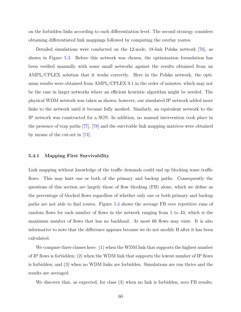
on the forbidden links according to each differentiation level. The second strategy considers
obtaining differentiated link mappings followed by computing the overlay routes.
Detailed simulations were conducted on the 12-node, 18-link Polska network [76], as
shown in Figure 5.3. Before this network was chosen, the optimization formulation has
been verified manually with some small networks against the results obtained from an
AMPL/CPLEX solution that it works correctly. Here in the Polska network, the opti-
mum results were obtained from AMPL/CPLEX 9.1 in the order of minutes, which may not
be the case in larger networks where an efficient heuristic algorithm might be needed. The
physical WDM network was taken as shown; however, our simulated IP network added more
links to the network until it became fully meshed. Similarly, an equivalent network to the
IP network was constructed for a SON. In addition, no manual intervention took place in
the presence of trap paths [77], [78] and the survivable link mapping matrices were obtained
by means of the cut-set in [74].
5.4.1 Mapping First Survivability
Link mapping without knowledge of the traffic demands could end up blocking some traffic
flows. This may hurt one or both of the primary and backup paths. Consequently the
questions of this section are largely those of flow blocking (FB) alone, which we define as
the percentage of blocked flows regardless of whether only one or both primary and backup
paths are not able to find routes. Figure 5.4 shows the average FB over repetitive runs of
random flows for each number of flows in the network ranging from 1 to 43, which is the
maximum number of flows that has no backhaul. At most 66 flows may exist. It is also
informative to note that the difference appears because we do not modify H after it has been
calculated.
We compare three classes here: (1) when the WDM link that supports the highest number
of IP flows is forbidden; (2) when the WDM link that supports the lowest number of IP flows
is forbidden; and (3) when no WDM links are forbidden. Simulations are run thrice and the
results are averaged.
We discover that, as expected, for class (3) when no link is forbidden, zero FB results.
60

0 1 2 3 4 5 6 7 8 9 101112131415161718192021222324252627282930313233343536373839404142430
10
20
30
40
50
60
70
80
90
100
Number of traffic flows
Flow
blo
ckin
g (F
B)
BR when routed before forbidding
High traffice link forbiddenlow traffic link forbiddenNo link forbidden
Figure 5.4: Flow blocking in mapping first survivability
No clear-cut difference exists between the other two. But there is a likelihood in these two
classes, which also applies to other network topologies, that banning a link with high use, in
this case link 7, is likely to block more traffic than banning a link with low use, in this case
link 3. Although complicated in settings, this explanation is intuitive and understandable.
However, we would also like to point out here that the difference in FBs among a number of
forbidden links is not significant as compared to that when no link is forbidden; therefore,
we identified a better strategy that involves simply reversing the order of computation.
61
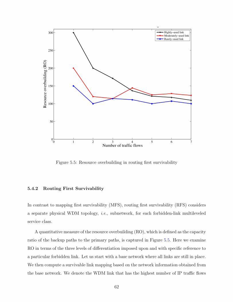
0 1 2 3 4 5 6 70
50
100
150
200
250
300
Number of traffic flows
Reso
urce
ove
rbui
ldin
g (R
O)
RO when routed after forbidding
Highly used linkModerately used linkRarely used link
Figure 5.5: Resource overbuilding in routing first survivability
5.4.2 Routing First Survivability
In contrast to mapping first survivability (MFS), routing first survivability (RFS) considers
a separate physical WDM topology, i.e., subnetwork, for each forbidden-link multileveled
service class.
A quantitative measure of the resource overbuilding (RO), which is defined as the capacity
ratio of the backup paths to the primary paths, is captured in Figure 5.5. Here we examine
RO in terms of the three levels of differentiation imposed upon and with specific reference to
a particular forbidden link. Let us start with a base network where all links are still in place.
We then compute a survivable link mapping based on the network information obtained from
the base network. We denote the WDM link that has the highest number of IP traffic flows
62

– primary and backup paths – routed upon it as a “highly-used link”. In the same manner,
“moderately-used link” and “rarely-used link” can be found. In particular, the indexed links
9, 4, and 3 are classified as highly-, moderately-, and rarely-used links, respectively.
In order to fairly compare the ROs of the three classes, we show an average value over
a random order of the same set of flows. We demonstrate the results in Figure 5.5. This
figure, together with Figure 3 in [71], suggests that there is room for improvement if we
could consider both mapping and routing jointly.
However, an intriguing part of the results shows how link protection can now play a role
for RO. By looking closely at the number of flows each link carries, we observe that nearly all
edge links, i.e., 8 out of 9, carry more traffic than the rest. This is because traffic in an edge
link tends to have fewer routing choices when it comes to failure; in fact, this link already
provides the best routes in terms of RO when there is no link forbidden. This implies that
links at the edge of a network may be of more importance when considering protection from
failure.
5.4.3 Joint Mapping-Routing Survivability
Though we are primarily concerned in this dissertation work with differentiated mapping for
survivability, it is important to point out here that some improvements over both FB and
RO can be made if link mapping and flow routing are optimized jointly. Our work is different
from [71] in that it considers differentiated link mapping in addition to joint mapping and
routing survivability. This allows us to examine what benefits it can provide for different
classes of services without compromising for performance.
5.5 SUMMARY
The profound benefits of any network include the ability to provide a variety of multileveled
service classes to different customers. We identified a novel metric that can be included
in the survivability design for multi-leveled differentiation in any layered network graphs
63

and elaborate its use through an optimization-based network model. We also considered
the logical link and the traffic layer separately that would otherwise be indistinguishable in
traditional ways. Our study showed that the two solution approaches offer some trade-offs to
consider when deciding whether flow blocking or resource overbuilding is of more importance.
The findings are illustrated through numerical results.
64

6.0 LINK AVAILABILITY NETWORK MAPPING
Core networks are increasingly supporting overlay networks on top of an IP-WDM network.
As network reliability is a growing concern, a major challenge in the survivable layered
network design is the crosslayer survivable mapping problem that deals with QoS parameters
such as availability as well as many others. This work directly studies this problem and
proposes matrix formulations of the NP-hard mapping problem, giving a detailed insight
into the structure of the layered network as well as relationships between and among links and
some potential mapping extensions. Numerical experiments show that intelligent crosslayer
mapping can result in availability gains at little and occasionally no expense to the routing
cost. The remainder of this chapter is arranged as follows: Section 6.2 gives our notation
and definition of the problem. Section 6.3 provides the matrix formulations and presents
them in different optimization goals. Section 6.4 presents the results of a detailed example
of link availability mapping. Finally, we provide a summary of the work in this chapter in
Section 6.5.
6.1 INTRODUCTION
As precursors to the future architecture of the Internet, overlays are not only adding one
additional layer into the networks; but on a growing scale, they take a role of computing
routes and delivering information among service points that arise to serve a range of diverse
requirements upon the application [54]. In a general network environment, the overlay has
to be supported by an infrastructure network, so that the full potential of high bandwidth
can be realized; this network is typically IP-over-WDM technology.
65

(a) Overlay layer (b) IP layer (c) WDM layer
Figure 6.1: The three network layers, constituting an overlay-IP-WDM network
Overlay networks that can support applications with specific requirements are key el-
ements to generating new sources of revenue. The needs are generally pressed by service
requests with more granular level of performance guarantee or by scaling flaws in the original
design of the Internet; particularly, when traffic runs across multiple Internet domains [79].
To meet these challenges, several commercial virtual network operators (VNOs) [53], [80],
[81], [82], [83], [84], [85], [86] have managed to construct service overlay networks (SONs)
that can provide secure and guaranteed application delivery to the customers.
Unfortunately, our understanding of the fundamental property of the layered network ar-
chitecture, ranging from the effect and interaction among network layers, capacity allocation,
and network and traffic survivability, is still in its infancy or waiting for more development.
One known problem is failure propagation – a situation in which a failure in a lower-layer net-
work can result in one or more failures in an upper-layer network. Chapter 4 has considered
this problem in layered network in detail and developed crosslayer survivable mapping [12],
which considered link mapping between network layers, such that the upper-layer network
is still survivable, i.e., connected, when any link in the lower-layer network fails.
In this chapter, we take a vertical look at the whole structure of the overlay-IP-WDM
network architecture as an instance of a three-layer network by considering the relationship
66
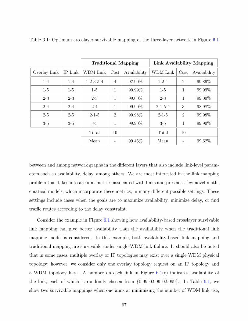
Table 6.1: Optimum crosslayer survivable mapping of the three-layer network in Figure 6.1
Traditional Mapping Link Availability Mapping
Overlay Link IP Link WDM Link Cost Availability WDM Link Cost Availability
1-4 1-4 1-2-3-5-4 4 97.90% 1-2-4 2 99.89%
1-5 1-5 1-5 1 99.99% 1-5 1 99.99%
2-3 2-3 2-3 1 99.00% 2-3 1 99.00%
2-4 2-4 2-4 1 99.90% 2-1-5-4 3 98.98%
2-5 2-5 2-1-5 2 99.98% 2-1-5 2 99.98%
3-5 3-5 3-5 1 99.90% 3-5 1 99.90%
Total 10 - Total 10 -
Mean - 99.45% Mean - 99.62%
between and among network graphs in the different layers that also include link-level param-
eters such as availability, delay, among others. We are most interested in the link mapping
problem that takes into account metrics associated with links and present a few novel math-
ematical models, which incorporate these metrics, in many different possible settings. These
settings include cases when the goals are to maximize availability, minimize delay, or find
traffic routes according to the delay constraint.
Consider the example in Figure 6.1 showing how availability-based crosslayer survivable
link mapping can give better availability than the availability when the traditional link
mapping model is considered. In this example, both availability-based link mapping and
traditional mapping are survivable under single-WDM-link failure. It should also be noted
that in some cases, multiple overlay or IP topologies may exist over a single WDM physical
topology; however, we consider only one overlay topology request on an IP topology and
a WDM topology here. A number on each link in Figure 6.1(c) indicates availability of
the link, each of which is randomly chosen from {0.99, 0.999, 0.9999}. In Table 6.1, we
show two survivable mappings when one aims at minimizing the number of WDM link use,
67

denoted ‘cost’, and the other aims at maximizing the total availability of the IP network,
which is mapped on the WDM network. The last two rows show total cost and mean
availability of the two mapping schemes. In this particular example, we can see that the link
availability mapping gives higher availability at no expense to the number of WDM links. It
is noteworthy in the traditional mapping that IP link 1-4 is mapped to WDM links 1-2-3-
5-4 because the survivability is required; otherwise, it would have taken WDM links 1-2-4,
and because we aim at maximizing the average availability, it is possible that some links
are higher in availability than the link availability mapping counterpart, i.e., IP link 2-4.
Clearly, we get a free ride to higher availability by taking advantage of the two degenerate
solutions – the situation in which two distinct mappings have the same cost, i.e., use the
same number of WDM channels or wavelengths. We will show later in this paper that in
general there is a tradeoff between the two criteria: availability and cost, or to sacrifice one
for the other.
In this chapter, we introduce mathematical formulations that capture the link-level avail-
ability metric and the survivable link mapping problem in matrix models as well as other
QoS metrics that could also be considered as link parameters. In the formulations, we derive
for the first time the link mapping problem in a matrix form such that it can easily be inte-
grated with the capacity allocation problem laying a path for future work to further explore
the joint optimization of the two problems using the given formulation and model.
6.2 TERMINOLOGY AND PROBLEM DEFINITION
In this section we present the terminology and the problem considered in this chapter.
6.2.1 Terminology
We consider an uncapacitated network in each of the three network layers. Let a network
be denoted by a set of nodes N l and a set of links Ll, where l is the layer index. Here we
consider l = 1, 2, 3 as WDM, IP, and overlay layers, respectively. Each link is equivalent
68

to two unidirectional links with an equal number of wavelengths and the same failure state,
i.e., available or failed, in each link and with the same failure probability. Furthermore, let
Bk denote the incidence matrix, and let Hji : Lj 7→ Li be a link mapping from network layer
j to network layer i where each layer j link is assigned to a subset of layer i links [12]. The
matrix Hji is called link mapping matrix.
6.2.2 Problem Definition
We now define the problem of interest regarding the link mapping matrix. We say a link
mapping Hji is survivable under a single-link failure if layer j network remains connected
after any layer i link fails. Generally, we call Hji a survivable mapping under n-link failures
when it can withstand up to n concurrent link failures. The matrix can also be extended to
include cases when link metrics are considered and when their summation is to be optimized
or constrained.
6.3 MATRIX FORMULATIONS OF SURVIVABLE MAPPING
This section presents graph-based matrix-formulated optimization models for the survivable
mapping problem in three categories: Guaranteed, optimized, and constrained mappings,
each of which is discussed in each of the following sections, respectively.
6.3.1 Notation
This section provides a summary of the notation used in this chapter.
l Network layer index, where l = 1, 2, 3 refers successively to higher layers
N l Layer l node set
Ll Layer l link set
Bl Layer l incidence matrix with dimension |N l| × |Ll|
C l Layer l segment-set matrix with dimension |2|N l|−1 − 1| × |Ll|
CNMl Layer l crosslayer node mapping matrix with dimension |N l| × |N l−1|
69

Hji Survivable link mapping matrix between layers j and i (H1
0 = I)
e The column vector of all ones
6.3.2 Guaranteed Network Mapping
Nearly all the existing literature has assumed that a crosslayer survivable mapping that is
resilient to a single-link failure, can be obtained from the likes of [74], [87], among others. In
this section, we first derive an expression for the mapping in a matrix form and extend the
model to include cases of a multiple-link failure in a layered network, we then modify the
objective function to apply these extensions to the situation in which we wish to maximize
the minimum number of physical-layer link failures that would disconnect the upper layer
network topology.
6.3.2.1 Network Mapping for Single-Link Failures Given the notation previously
defined, we formulate the survivable link mapping problem with an introduction of parame-
ters Ck and CNMk, representing all possible segments of layer k network and crosslayer node
mapping, respectively. Since an upper-layer network can be disconnected due to only some
link failures in a lower-layer network even when the lower-layer network is still connected,
we lose much of the original meaning of cut-set in a single-layer network when a multilayer
network architecture is considered. Segment-set can simply be defined as a cut-set of the
upper-layer network. The formulation for crosslayer survivable network mapping under a
single-link failure can be expressed as follows:
minH3
2 ,H21
eT H32 H
21 e, (6.1)
Hk+1k BkT CNMk+1T = Bk+1T , k = 1, 2, (6.2)
[Ck+1 e]− Ck+1Hk+1k � 1, k = 1, 2, (6.3)
H32 H
21 � 1. (6.4)
Objective (6.1) defines the optimization goal, aimed at minimizing the number of links
used in layer 1. Constraint (6.2) deals with the conservation of mapped links. Let CNMk
be a matrix of one-to-one crosslayer node mapping from network layer k to layer k − 1 in
70

which a diagonal entry (i, j) is one if and only if node i of layer k is associated to node j in
layer k − 1, zero otherwise. We consider node mapping from network layer k to k − 1 such
that a set of layer k node indices is a subset (⊆) of a set of layer k − 1 node indices1. It is
noteworthy here and throughout the paper that we assume the number of layer k nodes is
no greater than that of layer k− 1 nodes; if this is not the case then we further assume that
all layer k nodes that are associated with the same k− 1 node can be considered as a single
super-node.
Survivability under a single-link failure is recognized in constraint (6.3), where Ck is a
segment-set matrix in which the rows correspond to the segment-sets and the columns to
the layer k links of the network. Reference [89] gives the total number of segment-sets in a
network graph as 2|Nk|−1 − 1, where N k is the number of nodes in layer k network; hence,
the segment-set matrix has dimensions (2|Nk|−1 − 1, |Lk|). In this constraint, there are two
components on the left hand side: The first component refers to the number of links that
belong to a segment-set, represented by each element of the column vector Ck+1 e. In the
second component, each row refers to the number of links that would fail as a result of a
failure in a layer 1 link, represented by each matrix column. The 1 on the right hand side
of the constraint implies that two segments of layer k + 1 network are still connected with
at least one link when a single-link failure occurs. In other words, there is at least one
surviving link when a failure occurs. The symbol [u] on the left hand side defines a matrix
comprising |Lk| column vector u’s, that is [u] = [uu . . . u]. In other words, [u] defines a
matrix constructed by augmenting a u column vector to the right-hand side |Lk| − 1 times.
The symbol � denotes vector-scalar inequality or componentwise inequality: A � 1 means
A(i, j) ≥ 1 for all elements (i, j) of the matrix A. Constraint (6.4) defines mapping with
no backhaul as previously discussed in [12]. Similar to constraint (6.3), the symbol � in
constraint (6.4) implies that A � 1 means A(i, j) ≤ 1 for all elements (i, j) of the matrix A.
6.3.2.2 Network Mapping for n-Link Failures Here we present a generalization of
the model presented in the preceding section by considering a multiple-link failure in the
1Column switching, i.e., node renumbering, may be required when the indices do not follow the assump-tion. This can be implemented by multiplying a corresponding (0, 1)-matrix to both sides of the constrainton the right-hand sides after column(s) of zeros is augmented [88], and |N (k)| ≤ |N (k−1)| still holds.
71

layered network. A model can be formulated as follows:
minH3
2 ,H21
eT H32 H
21 e, (6.5)
Hk+1k BkT CNMk+1T = Bk+1T , k = 1, 2, (6.6)
[Ck+1 e]− Ck+1Hk+1k � n, k = 1, 2, (6.7)
H32 H
21 � 1. (6.8)
Objective (6.5), and constraints (6.6) and (6.8) have a similar description as given previ-
ously. Constraint (6.7) is a generalized version of constraint (6.3) when at most n links fail
simultaneously, e.g., dual-failure [90].
6.3.2.3 Max-Min Survivable Network Mapping This formulation considers the net-
work mapping problem with a goal of maximizing the minimum number of failures that would
disconnect the network. The problem can be stated as follows:
minH3
2 ,H21 ,n
eT H32 H
21 e− n, (6.9)
Hk+1k BkT CNMk+1T = Bk+1T , k = 1, 2, (6.10)
[Ck+1 e]− Ck+1Hk+1k − n � 0, k = 1, 2, (6.11)
H32 H
21 � 1. (6.12)
Here we consider n as an optimization variable that is in contrast to the one in constraint
(6.7), which holds it to a fixed number of concurrent failures. In accordance with techniques
in solving min-max or max-min optimization problems, we include our n in the objective
function (6.9), which is to be maximized. This is equivalent to minimizing −n because we
consider n a strictly positive integer number. The similar idea has also been explored in [9].
Alternatively, the n can also be further defined at a more granular level, i.e., per segment-
set, where connectivity between two distinct segments of a network may be required to
be stronger than the connectivity of the remaining two others. It can also be defined per
physical-link failure when a particular link is more vulnerable to failures than others.
72

6.3.3 Optimized Network Mapping
We consider crosslayer survivable mapping aimed at optimizing a particular performance
metric associated with links in this section. In order to accomplish so, the objective functions
presented in Section 6.3.2 can be modified to embrace link-level metrics, so that they can be
optimized. This section directly considers optimized network mapping under any single-link
failure, but can be extended to cases of multiple failures and max-min failures upon taking
into account the models presented in Sections 6.3.2.2 and 6.3.2.3, respectively.
In the area of QoS routing, the following cost function [91] has been widely used to study
the feasibility problem and to design routing algorithms under multiple constraints:
gλ(p) , (w1(p)
c1)λ + (
w2(p)
c2)λ + . . .+ (
we(p)
ce)λ, (6.13)
where we(p) ≤ ce is a eth additive constraint for path p and λ is a positive nonlinear factor. A
minimization of the function gives a range of solutions from generalized linear approximation
(GLA) (λ = 1) to an asymptotically exact solution (λ → ∞). Here we consider the special
case of λ = 1. Without loss of generality, we also consider ce = 1 for all e’s and associate each
we(p) with a link-level metric for each link e, then we include the minimization of function
gλ(p) in the following optimized network mapping model in which it is simply referred to as g.
minH3
2 ,H21
eT H32 H
21 g, (6.14)
Hk+1k BkT CNMk+1T = Bk+1T , k = 1, 2, (6.15)
[Ck+1 e]− Ck+1Hk+1k � 1, k = 1, 2, (6.16)
H32 H
21 � 1. (6.17)
Objective (6.14) deals with aspects of the model of designing network mapping based on
additive metrics such as delay, jitter, packet loss budget, linear link cost, WDM link distance,
among others. The vector g consists of ge’s, where each ge represents a cost associated with
each link e in layer 1 network. The descriptions of constraints (6.15)-(6.17) have already
been given in Section 6.3.2.1.
73

6.3.4 Constrained Network Mapping
While the preceding section considered optimizing the summation of the metrics, this section
considers an upper bound of the summation. An example includes delay-bound mapping. An
optimization-based formulation for constrained network mapping can be written as follows:
minH3
2 ,H21
eT H32 H
21 e, (6.18)
Hk+1k BkT CNMk+1T = Bk+1T , k = 1, 2, (6.19)
[Ck+1 e]− Ck+1Hk+1k � 1, k = 1, 2, (6.20)
H32 H
21 � 1, (6.21)
H32 H
21 b � bc. (6.22)
The formulation is similar to that presented in Section 6.3.2.1 but with constraint (6.22)
added. This constraint puts a requirement on the summation of a metric in each layer 1 link
that is used by a layer l link. In this constraint, the vector b consists of be’s, where each
be represents a cost associated with each link e in layer 1 network, and the scalar bc is an
upper bound for layer l links. Alternatively, this bc can also be further defined per layer l
link when a requirement is different for each layer l link. That is, constraint (6.22) can be
replaced by constraint (6.23) expressed as follows:
H32 H
21 b � bc, (6.23)
where bc consists of bc’s, where each bc represents each upper bound for a layer l link.
6.3.5 Solving the Optimization Problems
In order to solve the presented matrix formulations, we first assume that network information
in every network layer, i.e., nodes, links, is known or given and then use CPLEX [92],
which generally relies on a branch-and-bound algorithm to solve these problems. In general,
solving time is exponential because our problems are NP-hard; therefore, scalability is still
an issue, pressing for efficient algorithms as part of future work. In the next section, we give a
small example detailing the computational steps in obtaining optimum crosslayer survivable
mapping in a layered network.
74

6.4 DETAILED SAMPLE RESULTS
In this section we give an example of availability-maximized mapping based on the presen-
tation in Section 6.3.3 and provide some useful information from each computation step for
appreciation of the models.
We consider a three-layer network in Figure 6.2, where CNM2 = CNM3 = I, and availability
of each link is known or given. All link indices are shown, and the incidence matrices for
layer 1, layer 2, and layer 3 networks, respectively, can be expressed as:
B(1) =
1(1) 2(1) 3(1) 4(1) 5(1) 6(1) 7(1)
A(1) 0 0 0 1 0 1 1
B(1) 0 1 1 1 0 0 0
C(1) 1 1 0 0 0 0 0
D(1) 0 0 0 0 1 0 1
E(1) 1 0 1 0 1 1 0
,
and B(l) =
1(l) 2(l) 3(l) 4(l) 5(l) 6(l)
A(l) 0 1 0 1 0 1
B(l) 0 0 1 0 1 1
C(l) 1 1 1 0 0 0
D(l) 1 0 0 1 1 0
,
for l = 2 and 3. The segment-set of network layer 3 in the considered network can be
enumerated and represented in a matrix form as follows:
C(3) =
1(3) 2(3) 3(3) 4(3) 5(3) 6(3)
1 0 1 0 1 0 1
2 0 0 1 0 1 1
3 1 1 1 0 0 0
4 1 0 0 1 1 0
5 0 1 1 1 1 0
6 1 0 1 1 0 1
7 1 1 0 0 1 1
,
75
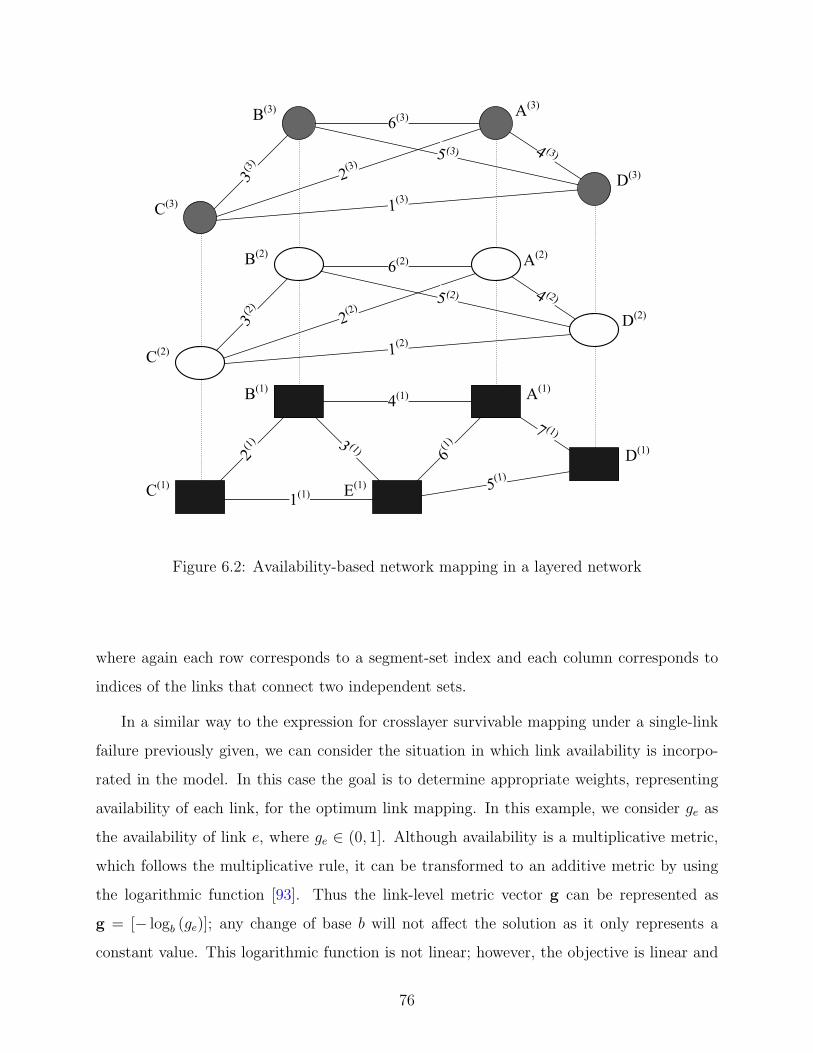
(3)
(3)(3)
(1)
(1)(1)
(1)
(1)
(1)
(2)
(2)
(2)
(2)
(3)
(3)(3)
(1)
(3)(3)
(3)
(3)
(2)
(2)
(2) (2)
(1)
(2)
(1)
(1)
(1)(1)
(2)
Figure 6.2: Availability-based network mapping in a layered network
where again each row corresponds to a segment-set index and each column corresponds to
indices of the links that connect two independent sets.
In a similar way to the expression for crosslayer survivable mapping under a single-link
failure previously given, we can consider the situation in which link availability is incorpo-
rated in the model. In this case the goal is to determine appropriate weights, representing
availability of each link, for the optimum link mapping. In this example, we consider ge as
the availability of link e, where ge ∈ (0, 1]. Although availability is a multiplicative metric,
which follows the multiplicative rule, it can be transformed to an additive metric by using
the logarithmic function [93]. Thus the link-level metric vector g can be represented as
g = [− logb (ge)]; any change of base b will not affect the solution as it only represents a
constant value. This logarithmic function is not linear; however, the objective is linear and
76

convex, thereby allowing us to use the same model with only a modification in the objective
function. It is noteworthy that we do not consider ge = 0 simply because (1) logb (0) is
undefined, and (2) a link with zero availability is not part of a graph. In this example,
we consider availability of a link randomly chosen from any one of 0.99, 0.999, and 0.9999.
These numbers are used here for illustration purposes only, but the model is applicable to
other values of link availability as well.
By solving the model given earlier in Section 6.3.3, we identify the two mapping matrices
aimed at maximizing the total availability of the layer 3 network as a result of layer 1 link
availabilities. The results named “Maximum availability” are as follows:
H21 =
1(1) 2(1) 3(1) 4(1) 5(1) 6(1) 7(1)
1(2) 1 0 0 0 1 0 0
2(2) 1 0 0 0 0 1 0
3(2) 0 1 0 0 0 0 0
4(2) 0 0 0 0 0 0 1
5(2) 0 0 1 0 1 0 0
6(2) 0 0 1 0 0 1 0
,
and H32 = I6,
both of which are survivable under single-link failure and the multiplication of which, con-
sidering the two sub two-layer networks, has no backhaul.
Two other mapping schemes based on the model given in Section 6.3.2.1 aimed at min-
imizing the number of WDM links are presented for completeness of the example. The
following matrices represent the first solution, denoted as “Minimum link #1”:
H21 =
1(1) 2(1) 3(1) 4(1) 5(1) 6(1) 7(1)
1(2) 1 0 0 0 1 0 0
2(2) 0 1 0 1 0 0 0
3(2) 0 1 0 0 0 0 0
4(2) 0 0 0 0 0 0 1
5(2) 0 0 1 0 1 0 0
6(2) 0 0 0 1 0 0 0
,
77

Table 6.2: Availability and cost of mapping schemes
Mapping Cost Mean Availability (min∼max)
Maximum availability 10 99.41 (98.90∼99.90)
Minimum link #1 9 99.12 (98.01∼99.90)
Minimum link #2 9 98.95 (98.01∼99.90)
and H32 = I6.
The following matrices represent the second solution, denoted as “Minimum link #2”:
H21 =
1(1) 2(1) 3(1) 4(1) 5(1) 6(1) 7(1)
1(2) 1 0 0 0 1 0 0
2(2) 0 1 0 1 0 0 0
3(2) 0 1 0 0 0 0 0
4(2) 0 0 0 0 0 0 1
5(2) 0 0 0 1 0 0 1
6(2) 0 0 0 1 0 0 0
,
and H32 = I6.
By looking at the number of links used in each mapping scheme, we observe that these
two mappings are degenerate, i.e., have the same cost. The number of link use can be
identified by the number of 1’s in each matrix. For example, in “Minimum link #2”, the
number of link use is 9, which is identified by the number of 1’s in the product matrix H32 H
21 .
Tabulated results are presented in Table 6.2, which shows that the average availability
over all overlay paths is largest when availability is considered in the mapping design. The
‘cost’ column in the table is the number of links used. In the result, availability of each
overlay link is calculated and recorded, the minimum and the maximum of which are taken
from the record and shown by numbers in parentheses in the table. Then mean is also
calculated and shown in the same column outside the parentheses. The table shows that
78

the “Maximum availability” mapping gives the highest availability among all of the three
considered mapping schemes. In particular, it is the best among all availability measures,
including mean, min, and max availabilities. Nevertheless, this comes at an expense of cost,
implying that we overly use the one more WDM link, compared to the two other mappings.
Now we look at “Minimum link #1” and “Minimum link #2”, we can see that both of which
share the same cost, but with different availability. The first mapping gives slightly better
availability, however, at the same cost as “Minimum link #2” unveiling the preference of
equal cost mapping with more availability. After all, we may need more information related to
capital expenditures (CapEx) or operational expenditures (OpEx) or both to decide whether
0.29% increased mean availability, which is 99.41% less 99.12%, is worth a WDM lightpath
and revenue from reliability-focused customers.
6.5 SUMMARY
Common weaknesses of the work aimed at attacking the survivability problem in the layered
communication systems include the lack of work that examines the problem from the perspec-
tive of the whole network architecture. In this chapter, we formulated several mathematical
formulations of network mapping in a variety of settings and requirements, and specifically
consider the availability-based link mapping in layered network graphs, considering both
availability and survivability. A numerical example is given and presented in detail. Possi-
ble extensions include further investigation on the formulations in other network topologies;
these may also include the explicit existence of traffic layers, and joint optimization of the
mapping and routing problems.
79

7.0 SURVIVABILITY OF MULTILAYER TRAFFIC
The survivability of backbone networks to failures is an on-going concern. We put more fo-
cus on the lower two layers in this chapter, as they constitute a core backbone and examine
capacity planning strategies and their tradeoffs in the network when traffic may be present
in every layer. This chapter addresses the tradeoff between each pair of the four possible
survivability strategies in a two-layer network setting under multilayer traffic ratios. We ex-
plicitly consider an IP-over-WDM scenario as an instance of the core backbone networks; we
examine closely how each survivability strategy behaves in this network and report numerical
results at the end of the chapter.
7.1 INTRODUCTION
7.1.1 Motivation
Revenue-generating IP and optical-switching WDM networks are moving toward an inte-
grated high-speed backbone architecture with GMPLS as a common control plane. The
ability of the network to survive link or node failures will be a required feature in future net-
work infrastructure. However, multilayer planning is necessary to guarantee the survivability
of traffic in a two-layer backbone network.
Survivability of the traffic at both layers is essential as bandwidth at the lightpath level
is becoming more in demand by customers [94]. Such layer 1 customers purchase lightpaths
connecting between end-points in the WDM layer for providing connectivity in a private
network. However, providing survivability to both IP flows and lightpaths is challenging.
80

In most cases, these two-layer networks are under the same administrative ownership, but
since the layers are formed by different technologies, interoperability between two layers of
different technologies has become increasingly important.
7.1.2 The Proposed Evaluation Approach
Similar to much of the work in this area, we jointly consider capacity allocation and routing
assignment problems as a spare capacity allocation (SCA) problem. This SCA problem has
also been considered in the previous chapters. In this chapter, we examine several strategies
for survivability in two-layer networks when traffic originates at both layers and grooming
of the traffic, in each layer, is available at the edge. These strategies require traffic flows
in both layers to be survivable under single link failure at the bottom. In particular, the
following four survivability strategies are considered:
1. Strategy A: Backup paths are provided at the layer where traffic originates. Let BP tt be
a set of top-layer backup paths to protect top-layer traffic, and BP bb be a set of bottom-
layer backup paths to protect bottom-layer traffic. Sharing spare capacity between the
two backup path sets is not allowed.
2. Strategy B: Similar to Strategy A but capacity between the two backup path sets BP tt
and BP bb can be shared.
3. Strategy C: Backup paths of traffic at both layers are provided at the bottom layer.
Let BP tb be a set of bottom-layer backup paths to protect top-layer traffic and BP b
b as
previously defined. Sharing capacity between the two backup path sets BP tb and BP b
b is
not allowed.
4. Strategy D: Similar to Strategy C but the capacity between the two backup path sets
BP tb and BP b
b can be shared.
For all strategies, spare capacity may be shared within a backup path set, e.g., sharing
capacity among backup paths in BP bb is allowed. Sharing is also allowed in BP t
t as well as
in BP tb .
This chapter is organized in the following manner. In relation to Section 4.3, we present
a mathematical formulation of the two survivability strategies at the bottom, C and D in
81

Section 7.2. Performance evaluation of all strategies and numerical results are then given in
Section 7.3. Finally, our summary is given in Section 7.4.
7.2 SURVIVABILITY OF TWO-LAYER TRAFFIC
In this section, we extend the SCA model in [49] to include survivability strategies when
top-layer traffic is protected at the bottom layer. In this case, spare capacity due to the top
BP tb and bottom BP b
b layer traffic can either be unshared or shared. In addition, we consider
a disjoint backup path from its primary path. For brevity, the notation is taken from the
formulation presented in Section 4.3.1 and combined with superscripts denoting a two-layer
network architecture. For clarity, we restate some of the definitions here. The notation used
in this chapter is summarized as follows:
• from a {top, bottom}-layer perspective
N {t,b} {Top, Bottom}-layer node set
L{t,b} {Top, Bottom}-layer link set
F{t,b} {Top, Bottom}-layer flow vector
B{t,b} {Top, Bottom}-layer incidence matrix with dimension |N {t,b}| × |L{t,b}|
M{t,b} Diagonal matrix of bandwidth of {top, bottom}-layer flow f {t,b}
with dimension |F{t,b}| × |F{t,b}|
D{t,b} {Top, Bottom}-layer flow-node incidence matrix
with dimension |F{t,b}| × |N {t,b}|
P {t,b} Primary {top, bottom}-layer path matrix with dimension |F{t,b}| × |L{t,b}|
Q{t,b} Backup {top, bottom}-layer path matrix with dimension |F{t,b}| × |L{t,b}|
• from a bottom-layer perspective
Bt→b Top-layer incidence matrix with dimension |N b| × |Lb|
M t→b Diagonal matrix of bandwidth of top-layer flow f t with dimension |F t| × |F t|
Dt→b Top-layer flow-node incidence matrix with dimension |F t| × |N b|
P t→b Primary top-layer path matrix with dimension |F t| × |Lb|
Qt→b Backup top-layer path matrix with dimension |F t| × |Lb|
82

Gt→b Top-layer spare capacity matrix with dimension |Lb| × |Lb|
St→b Backup top-layer link capacity vector with dimension |Lb| × 1
Gb Bottom-layer spare capacity matrix with dimension |Lb| × |Lb|
Sb Backup bottom-layer link capacity vector with dimension |Lb| × 1
• General notation
H Survivable mapping matrix
e The column vector of all ones
Our network of interest is defined as follows: Given a bottom-layer directed network
with node set N b, link set Lb, and incidence matrix Bb [48], a top-layer directed network
with similar quantities in superscript t is constructed as follows: A node ntk ∈ N t, where
1 ≤ k ≤ |N t|, exists only if its associative node nbk ∈ N b at the bottom layer exists. That
is, N t ⊆ N b. No more than one top-layer node is allowed to associate with a node at the
bottom. Moreover, the presence of uncapacitated links at each layer is independent from
each other.
Let H be a binary survivable mapping matrix, where hij = 1 if a top-layer link i is
mapped onto a bottom-layer link j, and 0 otherwise. A survivable mapping matrix H can
be derived from a necessary condition of a two-connected network, as presented in [8]. Now
we have a topology construction including nodes, links, and link mapping. In the next two
subsections, we will provide formulations of the SCA problem due to two-layer traffic.
7.2.1 Providing Backup Paths to Top-Layer Traffic at the Bottom Layer
At the top layer, primary and backup paths of flows f t, where 1 ≤ f t ≤ |F t| are represented
by two 1×|Lt| binary row vectors ptf tlt and qtf tlt , respectively. The lt-th element in one of the
vectors equals one if and only if the corresponding path uses link lt. The path matrices [95]
P t and Qt are formed by a collection of ptf tlt and qtf tlt , respectively. The primary paths: P t,
can be obtained from Dijkstra’s shortest path algorithm. Let M t = diag({mtf t}|Ft|×1) be a
matrix of top-layer integral flow bandwidth. The top-layer traffic flows are represented by a
matrix Dt. An element dtf tnt of the matrix Dt equals 1 if the flow f t originates from node
nt and −1 if it terminates at node nt. Flows having identical end points, if they exist, are
treated as a single flow with flow bandwidth from those flow bandwidths combined.
83

In order to provide backup paths to top-layer traffic at the bottom, we need to map
top-layer information to the bottom. Because the incidence matrix is topology dependent, a
top-layer incidence matrix, when mapped to the bottom, is equivalent to that of the bottom.
This is shown in (7.1). In (7.2), bandwidth of the mapped top-layer flow still holds the same
value, i.e., mtf t , as that of the top-layer flow as it depends on flows only. Since a top-layer
network may not have the same number of nodes as the bottom, the flow-node incidence
matrix in (7.3) is mapped to the bottom layer by padding columns of zeros as necessary to
Dt. In (7.4), the link-mapping information in H is used to derive top-layer primary paths P t
from the perspective of the bottom layer, as P t→b. The � symbol is a matrix multiplication
operator, realizing the inclusive OR and AND operation, e.g., 1+1=1. Using this operator,
the logical relations among flows and links in a directed network can be simplified into one
matrix operation. It is noteworthy that in backhaul-free traffic routing (see the definition in
the Appendix), equation (7.4) is equivalent to the one where the � symbol is replaced with
the traditional matrix multiplication. Since binary flows are considered, we do not include
a single-path routing constraint in our ILP formulation as it would be redundant.
A mapping function f : t→ b can be described for each top-layer matrix as:
Bt→b = Bb (7.1)
M t→b = M t (7.2)
Dt→b = [Dt|0] (7.3)
P t→b = P t �H (7.4)
Using the notation and definitions given previously, the SCA problem of the top-layer
traffic can be formulated as:
Qt→bBt→bT = Dt→b (7.5)
P t→b +Qt→b � 1 (7.6)
Gt→b = Qt→bTM t→bP t→b (7.7)
St→b ∈ Z|Lb|
+ (7.8)
Qt→b : binary matrix (7.9)
84

Constraints (7.5) and (7.6) guarantee that a backup path matrix Qt→b is feasible via flow
conservation constraints and disjoint from the primary paths. A matrix Qt→b has the same
dimension as P t→b, which is |F t| by |Lb|. Constraint (7.7) determines the amount of spare
capacity units needed in order to protect mapped top-layer primary paths which fail as the
result of a single link failure at the bottom layer. This information is given in Gt→b, which
is a (|Lb|, |Lb|) matrix. An element gt→bij defines the spare capacity needed by bottom link i
to reroute failed paths in the face of failure at bottom link j. Equation (7.8) defines integer
variables, where Z|Lb|
+ is the set of nonnegative integral |Lb|-dimensional vectors; equation
(7.9) defines a (0,1)-matrix variable, which will be explained further in the next section.
7.2.2 Providing Backup Paths to Bottom-Layer Traffic at the Bottom Layer
Since providing backup paths to bottom-layer traffic at the bottom layer requires no mapping,
we now have all necessary information to find the backup paths of traffic in both layers. It
is equivalent to finding a set of disjoint primary-backup path pairs in single-layer networks.
A mathematical formulation for survivability of two-layer traffic at the bottom layer can be
written as:
QbBbT = Db (7.10)
P b +Qb � 1 (7.11)
Gb = QbTM bP b (7.12)
Sb ∈ Z|Lb|
+ (7.13)
Qb : binary matrix (7.14)
Similar to backup paths of top-layer traffic, a constraint set (7.10)-(7.14) defines backup
paths Qb = {qb}|F b|×|Lb| and the spare capacity Gb = {gb}|Lb|×|Lb| required to protect primary
paths P b of the bottom-layer traffic. As in Section 7.2.1, the primary paths P b can be
obtained from Dijkstra’s algorithm.
The objectives of the two strategies C and D are defined as follows: Strategy C has an
objective to minimize the spare capacity requirements of the two-layer traffic independently,
85

and so can be described as:
min (St→bT
+ SbT
) e, (7.15)
where St→b = row-max Gt→b, Sb = row-max Gb, and e is a column vector of ones. The
row-max (x) operation determines the maximum element in each row of the matrix x. This
min-max optimization of spare capacity requirements ensures the minimum capacity that
must be allocated for each bottom-layer link under single link failure at any other links.
The objective function of Strategy D is expressed as:
min (St→b,b)T e, (7.16)
where St→b,b = row-max (Gt→b +Gb). This strategy merges the two spare capacity matrices
and jointly consider them, allowing their spare capacity to be exchanged. The two surviv-
ability strategies at the bottom: C and D, and two strategies where traffic originates: A and
B [49], presented in the next sections, construct a basis for our study in this chapter.
7.2.3 Providing Backup Paths to Top-Layer Traffic at the Top Layer
In Strategies A and B when each backup path is provided in the layer where a primary path
is, we need to define the SCA problem of top-layer traffic at the top layer, which can be
formulated as:
QtBtT = Dt (7.17)
P t +Qt � 1 (7.18)
Gt = QtTM tP t (7.19)
St ∈ Z|Lt|
+ (7.20)
Qt : binary matrix (7.21)
In a similar way to the definition given previously, Constraints (7.17) and (7.18) guarantee
that a backup path matrix Qt is feasible via flow conservation constraints and disjoint from
the primary paths. A matrix Qt has the same dimension as P t, which is |F t| by |Lt|.
Constraint (7.19) determines the amount of spare capacity units needed in order to protect
mapped top-layer primary paths which fail as the result of a single link failure at the bottom
86

layer. This information is given in Gt, which is a (|Lt|, |Lb|) matrix. An element gtij defines
the spare capacity needed by bottom link i to reroute failed paths in the face of failure at
bottom link j. Equation (7.20) defines integer variables, where Z|Lt|
+ is the set of nonnegative
integral |Lt|-dimensional vectors; equation (7.21) defines a (0,1)-matrix variable.
Using the notation and constraints given previously in Section 7.2 and two constraint sets
(7.10)-(7.14) and (7.17)-(7.21), the objectives of the two strategies A and B can be stated
as follows: Strategy A has an objective to minimize the spare capacity requirements of the
two-layer traffic independetly, and so can be stated as:
min (St + Sb)T e, (7.22)
where St = row-max Gt. This min-max optimization of spare capacity requirements ensures
the minimum capacity that must be allocated for each link in their respective layer under
single link failure at any other links.
The objective function of Strategy B is expressed as:
min (St,b)T e, (7.23)
where St,b = row-max (Gt +Gb). This strategy merges the two spare capacity matrices and
jointly consider them, allowing their spare capacity to be exchanged.
In the following section, we study the four survivability strategies in an explicit context of
the IP-over-WDM two-layer networks using the given four exact matrix-based optimization
models. These optimization models have been manually verified on some small networks
against the results obtained from an AMPL/CPLEX implementation to ensure its correct-
ness.
7.3 NUMERICAL RESULTS AND ANALYSIS
In this section, we study the effects of the survivability strategies on spare capacity require-
ments of multilayer traffic in two-layer networks. First, we look at the impact of traffic ratios
between top- and bottom-layer in fixed network topologies as well as the impact of capacity
87
sharing between the two-layer traffic. Then, we look at the impact of top-layer network
connectivity in terms of average node degrees. We use AMPL/CPLEX 9.1 on a Sun Fire
V240, 2x1.2GHz UltraSPARC IIIi, 2GB to solve our models and the results are based on a
zero integrality gap, meaning that they are optimal.
A two-layer network topology with a number of network scenarios is considered to de-
termine the effects. The considered two-layer topology is Figure 1.1, which has been given
earlier in Chapter 1, where the top has 6 nodes, 9 links and the bottom has 10 nodes, 22
links. Primary paths in both layers, when needed, are precomputed and unchanged over
the course of simulations. A primary path is manually adjusted if the corresponding backup
path cannot possibly be obtained, called a trap path. This is a counterexample to the exis-
tence of two disjoint paths in two-connected networks, when there are no parallel links. We
are also aware that joint optimization of primary and backup paths often leads to better
capacity utilization [96]; but since we want to focus on the spare capacity requirements of
the survivability strategies, we let the primary paths be fixed. In addition, a number of
wavelengths and wavelength converters are assumed to be available and unit-capacity flows
are assumed.
7.3.1 Impacts of Traffic Ratios
In this section, the impacts of traffic ratios are discussed for the two possible settings: When
the number of bottom-layer flows is fixed while varying the number of top-layer flows, and vice
versa. With varying number of flows, f flows are chosen from the first f -th lexicographical
element of the combinations of two elements out of the node set, e.g., for 8 top-layer flows in
Figure 1.1, the considered flows are ({1, 2}, {1, 3}, {1, 4}, {1, 5}, {1, 6}, {2, 3}, {2, 4}, {2, 5}).
Spare capacity requirements are measured in terms of redundancy, or resource overbuilding
(RO), which is defined as a capacity ratio of backup paths to primary paths.
7.3.1.1 Varying Top-Layer Flows Over a fixed 45-flow bottom-layer network, Fig-
ure 7.1 shows by varying a number of top-layer flows that Strategy A and Strategy D perform
worst and best, respectively. The reasoning can be given as follows: Let us put aside bottom-
88

0 1 2 3 4 5 6 7 8 9 10 11 12 13 14 150
0.1
0.2
0.3
0.4
0.5
0.6
0.7
Numbers of top layer traffic flows
Red
unda
ncy
Strategy AStrategy BStrategy CStrategy D
Res
ourc
e ov
erbu
ildin
g (R
O)
Figure 7.1: Top-layer flows vs. resource overbuilding (|F b| = 45)
layer traffic to consider top-layer traffic only. There are two survivability strategies for the
top-layer traffic: Providing backup paths at the top layer and at the bottom. We claim that
the first strategy never requires fewer spare capacity units than the latter. The reasons are
as follows: First, a survivable matrix limits the number of feasible backup paths of top-layer
traffic at the bottom. This is because the matrix ties a top-layer link to bottom-layer links,
and this link mapping is not allowed to change. Second, spare capacity is provided by the
bottom layer; regardless of where backup paths are computed, their capacity requirements
are constrained by bottom-layer topology. This is also true even if the survivable matrix
can be changed because constraints will be at the bottom layer instead. In other words,
if the number of top-layer links are significantly fewer than that of the bottom then the
backup paths are limited by the top topology. But when the number of top-layer links are
significantly more than that of the bottom, a bottom topology itself limits improvements on
capacity sharing by its own topology. An example when these two strategies are equivalent
89

is when the two-layer topologies are identical and a survivable mapping is link-to-link. Now
let us put bottom-layer traffic back into consideration. We have shown that, for top-layer
traffic, bottom-layer backup paths require no more capacity than the top-layer counterpart.
This is also true when there is bottom-layer traffic and sharing spare capacity between BP bb
and BP tt or BP t
b is not allowed. Since capacity sharing usually reduces spare capacity re-
quirements, Strategy D always outperforms or at least performs as well as Strategy A. This
analysis supports other topologies as well.
The other two strategies, however, are competing. When a top-layer network has few
traffic flows, Strategy B outperforms Strategy C. This is because these few flows may well
be able to share capacity with the bottom flows. But when there are more flows at the top
layer, the situation is reversed.
Consider a scenario of 1 primary top-layer flow and 45 primary bottom-layer flows in
Figure 7.1. In this scenario, the bottom flows require 23 spare capacity units. Because of
capacity sharing, Strategy B requires only 1 more capacity unit to provide a backup path to
the top-layer flow. The total spare capacity required is now 24 units. However, in Strategy C,
when sharing is not allowed, the backup path requires 2 capacity units. The spare capacity
requirement of bottom-layer flows is never changed in Strategy C regardless of the number
of top-layer flows because they do not allow capacity sharing with the top flows. In this
scenario, primary paths require 1 and 71 capacity units for top- and bottom-layer flows,
respectively.
When there are more flows, i.e., more than 12 flows, in the top network, a higher number
of flows in both layers are subject to failures. In this scenario, Strategy C reduces spare
capacity requirements by giving more rerouting choices to the top flows. These choices offer
an advantage over Strategy B. A similar trend is also observed for different numbers of
top-layer flows, when bottom-layer flows are fixed, in Table 7.1.
7.3.1.2 Varying Bottom-Layer Flows In this section, we continue to evaluate Strat-
egy B and C, but instead, the number of top-layer flows is fixed, and we vary the number of
flows at the bottom layer.
Consider a scenario of 8 top-layer flows when the number of bottom flows ranges from
90

0 3 6 9 12 15 18 21 24 27 30 33 36 39 42 450
0.1
0.2
0.3
0.4
0.5
0.6
0.7
0.8
0.9
1
Numbers of bottom layer traffic flows
Red
unda
ncy
Strategy AStrategy BStrategy CStrategy D
Res
ourc
e ov
erbu
ildin
g (R
O)
Figure 7.2: Bottom-layer flows vs. resource overbuilding (|F t| = 8)
0 to 45, in multiples of 3. Unlike the setting in the previous section, this time Strategy
C requires fewer capacity units than Strategy B when the number of bottom-layer flows is
small. Figure 7.2 shows that Strategy B starts to outperform Strategy C when there are 15
flows in the bottom-layer network. These results conform with our previous discussions in
Section 7.3.1.1 in terms of traffic ratios.
Observations in this section and Section 7.3.1.1 suggest that there should be a charac-
teristic of the competing two survivability strategies, which could enable us to determine
which strategy to implement to ensure better capacity utilization according to each network
scenario. Due to its dependency on topology and mapping as well as backup path rout-
ing, we decide to omit the detailed discussion on the operating characteristics of the two
survivability strategies.
91
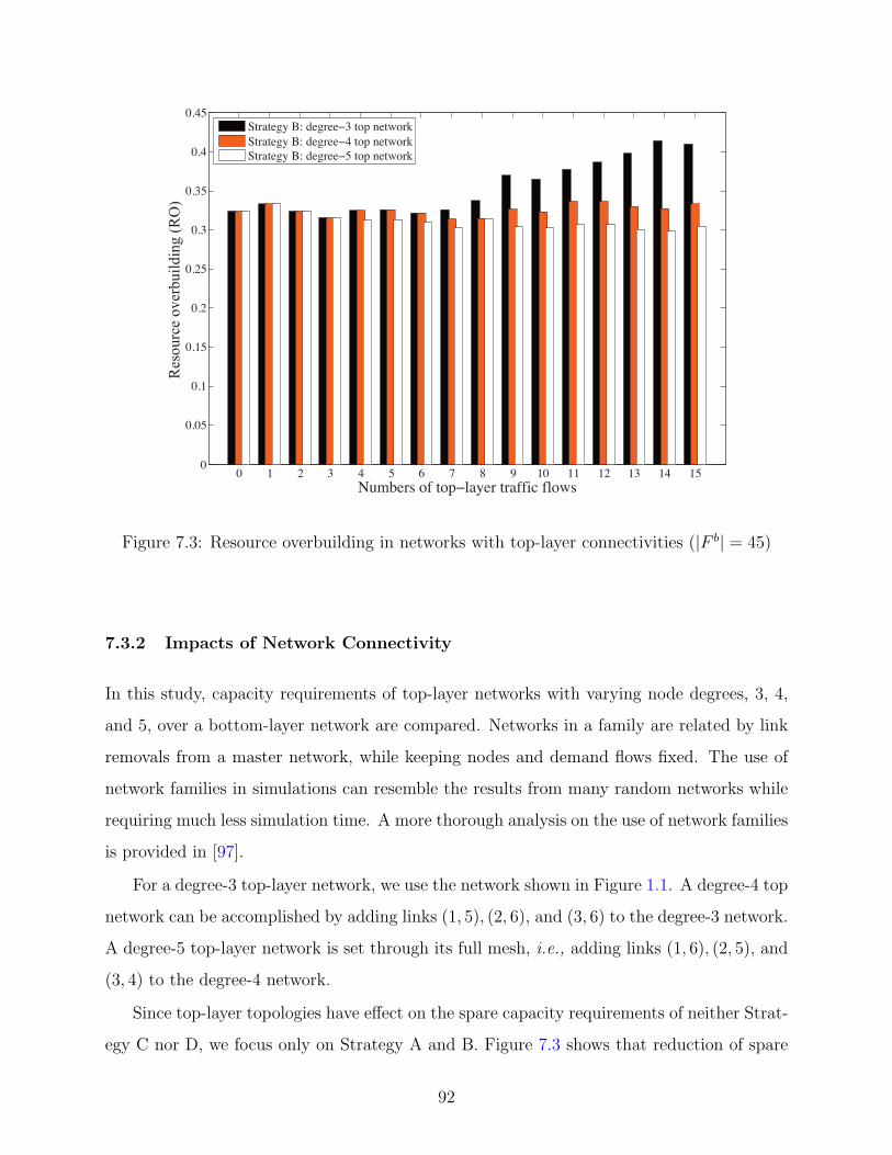
0 1 2 3 4 5 6 7 8 9 10 11 12 13 14 150
0.05
0.1
0.15
0.2
0.25
0.3
0.35
0.4
0.45
Numbers of top layer traffic flows
Red
unda
ncy
Strategy B: degree 3 top networkStrategy B: degree 4 top networkStrategy B: degree 5 top network
Res
ourc
e ov
erbu
ildin
g (R
O)
Figure 7.3: Resource overbuilding in networks with top-layer connectivities (|F b| = 45)
7.3.2 Impacts of Network Connectivity
In this study, capacity requirements of top-layer networks with varying node degrees, 3, 4,
and 5, over a bottom-layer network are compared. Networks in a family are related by link
removals from a master network, while keeping nodes and demand flows fixed. The use of
network families in simulations can resemble the results from many random networks while
requiring much less simulation time. A more thorough analysis on the use of network families
is provided in [97].
For a degree-3 top-layer network, we use the network shown in Figure 1.1. A degree-4 top
network can be accomplished by adding links (1, 5), (2, 6), and (3, 6) to the degree-3 network.
A degree-5 top-layer network is set through its full mesh, i.e., adding links (1, 6), (2, 5), and
(3, 4) to the degree-4 network.
Since top-layer topologies have effect on the spare capacity requirements of neither Strat-
egy C nor D, we focus only on Strategy A and B. Figure 7.3 shows that reduction of spare
92

capacity comes at an expense of a higher number of top-layer link installments in which a
significant difference in capacity savings is observed when the number of top-layer flows is
high. At 15 flows, which are the maximum number of distinct flows at the top, we observe
a capacity saving of 9 units from a degree-3 to degree-5 network, compared to 2 when there
are 8 flows at the top. One possible explanation is that an adding link can help reduce the
capacity requirements by giving more routing choices to the backup paths. This link has
little effect when there are few flows in the network, i.e., 1 - 3 flows.
7.3.3 Deployment Issues
This section describes some issues relating to the implementation of the four survivability
strategies in practice and discusses how they can be a key tool for the survivability in a
layered network.
While all four strategies can be implemented in any layered network that follows the
integrated network model, only two of them, i.e., A and B, are applicable to the overlay
network model. This is because the overlay model assumes a separate instance of the control
plane for each network layer [17] or for each managed network. When a network provider
owns and manages both of the technology layers, he will be able to choose the best surviv-
ability strategy among the four. However in a case when these two layers are administered by
different entities; for example, an ISP who owns only IP equipment and an optical network
provider who owns WDM switches, information sharing between these two network layers is
limited. Theoretically when this case happens, only strategies A and B are possible. The
actual implementation would also likely depend on how much and what kind of information
is being shared between the two managed networks.
7.4 SUMMARY
This chapter examines the four possible survivability strategies in two-layer core backbone
networks, where traffic is present at both layers. An optimization-based formulation is
93

proposed to investigate the spare capacity requirements under various traffic ratios and
network connectivities in the role of lightpath routing.
Numerical results show that the survivability of two-layer traffic at the bottom, when
sharing spare capacity among all backup paths is allowed, performs best. However, two of
the studied strategies are competing. Moreover, networks with higher average node degree
can provide more capacity savings, but this comes at the expense of link installments. Our
analysis and results provide important guidelines for the design of survivability strategies in
networks and for understanding their tradeoffs.
94

Table 7.1: Resource Overbuilding of Optimal Spare Capacity in Multilayer Traffic Scenarios†
Numbers of top-layer traffic flows
Num
ber
sof
bot
tom
-lay
ertr
affic
flow
s
0 1 2 3 4 5 6 7
0 — 300,300,100,100 133,133,67,67 100,100,60,60 78,78,67,67 92,92,50,50 85,85,46,46 80,80,47,47
3 100,100,100,100 133,100,100,100 113,88,88,88 100,80,80,80 86,79,79,79 94,76,65,65 89,72,61,61 85,70,60,60
6 91,91,91,91 108,100,92,100 100,86,86,86 94,88,81,81 85,75,80,70 91,83,70,70 88,79,67,67 85,77,65,62
9 88,88,88,88 100,88,88,88 95,84,84,84 90,81,81,76 84,76,80,72 89,75,71,68 86,72,69,66 84,71,68,65
12 71,71,71,71 82,73,77,73 79,71,79,71 77,65,77,65 73,67,73,63 79,67,73,61 76,65,71,62 75,92,67,58
15 59,59,59,59 68,61,64,61 67,60,67,60 66,56,66,56 64,58,64,56 69,59,64,54 68,58,63,53 67,57,60,52
18 55,55,55,55 63,59,59,59 62,56,62,56 61,56,61,53 60,55,60,53 65,53,60,51 64,52,59,50 63,52,57,48
21 46,46,46,46 53,50,50,50 53,48,53,48 52,48,52,45 52,48,52,52 57,47,53,45 56,46,52,44 56,46,50,42
24 43,43,43,43 49,46,46,46 49,44,49,44 49,44,49,42 49,47,49,45 54,44,50,42 53,43,49,42 53,44,47,40
27 41,41,41,41 47,44,44,42 47,43,47,43 47,41,47,41 47,43,47,42 52,41,48,39 51,40,47,39 51,41,46,37
30 38,38,38,38 43,41,41,39 43,39,43,39 43,38,43,38 44,40,44,39 48,40,45,38 48,39,44,38 48,40,43,37
33 36,36,36,36 41,37,39,37 41,36,41,36 41,34,41,34 42,37,42,35 46,37,43,35 45,36,42,35 46,37,41,34
36 36,36,36,36 40,37,39,37 41,36,41,36 41,34,41,34 42,37,42,35 46,37,43,35 45,36,42,35 45,37,41,34
39 34,34,34,34 39,35,37,35 39,34,39,34 39,33,39,33 40,36,40,34 44,36,41,34 43,35,41,34 43,36,39,33
42 33,33,33,33 37,34,35,34 37,33,37,33 38,33,38,33 38,34,38,33 42,34,39,33 41,34,39,33 41,34,38,32
45 32,32,32,32 36,33,35,33 36,32,36,32 37,32,37,32 38,33,38,31 41,33,39,31 40,32,38,31 41,33,37,30
Numbers of top-layer traffic flows
Num
ber
sof
bot
tom
-lay
ertr
affic
flow
s
8 9 10 11 12 13 14 15
0 94,94,44,44 100,100,48,48 88,88,40,40 89,89,41,41 87,87,37,37 88,88,38,38 94,94,36,36 91,91,35,35
3 96,83,57,57 100,88,58,50 90,80,50,47 91,81,50,50 89,77,46,49 89,76,46,46 95,82,45,45 92,79,44,44
6 59,79,62,62 97,84,63,59 89,78,56,56 89,76,55,55 88,76,51,54 88,77,51,51 93,80,50,50 91,78,49,49
9 91,71,65,59 95,76,65,54 88,71,59,51 88,70,58,51 87,67,54,50 88,69,54,48 92,71,53,47 90,70,52,46
12 82,67,67,56 86,69,64,52 80,65,61,48 81,67,63,50 80,67,59,49 81,66,58,47 85,69,57,46 84,67,56,45
15 73,60,60,51 77,63,58,48 73,60,56,44 74,61,57,46 74,63,54,46 75,63,54,44 78,65,53,43 77,64,52,43
18 69,55,57,47 73,58,56,44 70,55,54,43 71,57,55,43 70,59,52,43 71,59,52,41 75,61,52,41 74,60,51,40
21 62,49,51,42 66,52,50,40 63,50,48,39 64,52,50,41 64,54,48,39 65,54,48,38 69,56,47,37 68,55,46,37
24 59,47,48,40 62,49,48,38 60,48,46,37 61,49,48,39 61,51,46,39 63,51,46,38 66,53,45,37 65,53,45,36
27 56,44,47,37 60,46,46,35 58,45,45,35 59,46,46,37 59,49,45,36 61,49,45,36 64,51,44,35 63,50,44,35
30 53,41,44,36 57,43,43,35 55,42,42,34 56,44,44,35 56,46,42,35 58,46,43,34 60,48,42,33 60,48,41,33
33 51,38,42,34 54,41,42,32 53,40,41,32 54,41,43,33 54,43,41,33 55,44,41,32 58,45,41,31 57,45,40,32
36 50,38,42,34 53,42,42,32 52,41,41,32 53,42,42,34 53,43,41,34 55,44,41,33 57,46,40,33 57,46,40,32
39 48,38,41,33 51,41,40,33 50,40,40,33 51,41,41,33 52,43,40,34 53,44,40,33 55,46,39,33 55,45,39,33
42 46,35,39,33 49,39,36,32 48,38,38,32 49,39,39,32 49,40,38,32 51,41,38,31 53,43,38,31 52,43,38,32
45 45,34,38,31 48,37,38,30 47,36,38,30 48,38,39,31 49,38,38,31 50,40,38,30 52,41,38,30 51,41,37,30
†format: Strategies A, B, C, D
95

8.0 CONCLUSIONS AND FUTURE WORK
This chapter provides a summary of the dissertation, and suggests some possible extensions
and future work. The focus of this dissertation is to provide an analytical framework for sur-
vivability in layered networks. We considered a three-layer network in the explicit context of
an overlay-over-IP-over-WDM and investigated the relationship between and among network
layers. The major contributions and results of this dissertation have four core components,
all of which address issues related to the fundamental design problems of survivability in
multilayered networks as discussed below.
8.1 DISSERTATION SUMMARY
In this dissertation, we addressed a new issue related to the design of multilayer networks,
namely backhaul, which is a routing loop that occurred due to improper link mapping. This
backhaul can occur in any layered network graph of three or more layers, each of which
could be a network or traffic layer. We examined the network by dissecting it into two
different layers, which we called the network layer and the traffic layer. The first layer type
is defined per nodes and links whereas the latter is defined per communications pair. This
separate examination has allowed us to consider the two problems of network survivability
and traffic survivability in more detail. Table 8.1 shows a summary of our contributions and
Figure 8.1 illustrates the relationship between and among the major contributions presented
in Chapters 4 - 7. Although we differentiate network survivability from traffic survivability,
they are interconnected.
We first revealed the backhaul problem that may occur in a multilayer network and
96

Table 8.1: Summary of contributions
Crosslayer Network Traffic
Survivability Survivability Survivability
Approach Optimization
Theory/Model Crosslayer Forbidden Convex Survivability
Survivable Link Matrix Mapping Strategies
Mapping
Classified Ways to
Backhaul-free networks Maximize implement
Examples mapping where some availability/ survivability for
nodes/links guaranteed each traffic load
are hidden to services scenario
customers
proposed an efficient and effective implementation of crosslayer survivable mapping which
can overcome this problem. We proposed an optimization model that considers both of
the backhaul problem and the capacity allocation problem; this model is documented in
Chapter 4.
Then we extended the idea of backhaul-free network mapping and routing and further
considered ways to offer multi-leveled service in a multilayer network. We discussed two
possible approaches. The first approach was based on network differentiation. Different
customers could see different network topologies. The forbidden link matrix was introduced
such that it could be included in the original mathematical formulation. We demonstrated
that they can be integrated together well. We also made some observations that should
be useful in a survivable network design e.g., links at the edge of a network may be of
more importance when considering protection from failure. This model is documented in
Chapter 5.
The second approach was based on a link metric. We considered network mapping
97

Crosslayer Survivability in Overlay-IP-WDM
Networks
Network Survivability Traffic Survivability
Crosslayer Survivable Mapping
Differentiated Crosslayer Survivable
Mapping
Availability-based Crosslayer Survivable
Mapping
Survivability Strategies in a
Two-Layer Network
Figure 8.1: An illustration of the summary of contributions
and traffic routing in various convex network mappings. We examined the availability link
mapping in detail. This is the subject of the third part of the dissertation. We provided an
optimization model that included the availability metric in the original crosslayer survivable
mapping formulation showing that in some cases there are equal cost mappings, but some
have higher availability. This idea is very similar to that in Linear Programming sensitivity
analysis. This model is documented in Chapter 6.
In the final part of the dissertation, we looked more closely at traffic survivability in a
multilayer network. Because when there is no backhaul, a network of n layers can simply be
reduced to a two-layer network, we considered a two-layer network in this part. We developed
the matrix formulations of the four possible survivability strategies that can be implemented
in any two-layer network. We discussed in detail benefits and drawbacks of each choice
when traffic is present at each and every layer. This allows for the best implementation to
be chosen from the four possible survivability strategies in each traffic load scenario. The
strategies are documented in Chapter 7.
98
This research work is in the early stages of considering multilayer network design with
efficient link use and capacity allocation. When an optical WDM network is considered, this
link use refers to the efficiency of optical resources, channels or lightpaths. Although we used
an overlay-IP-WDM network as an explicit example of multilayer networks, this work can
be applied to any layered network graph. We further considered a case when traffic may be
present in a network; in this case, we further differentiated the traffic layer from the network
layer. This led us to a more thorough analysis of a survivable multilayer network design,
which is discussed throughout the dissertation.
8.2 FUTURE WORK
The work presented here can be extended in several directions. First, the investigation of
link mapping and traffic routing sheds some light on the relationship between and among
links and traffic in different layers as well as links which are forbidden. However, these
relationships could be further examined in the context of matrix algebra [98], [99]; some
examples are given in Table 8.2. Second, joint optimization of the two approaches also
deserves attention. We expect that it plays a role when taking the two criteria concurrently.
These problems could be central to our future research.
Built upon the work in this dissertation, the immediate future work would include:
• Including additional numerical results for a various number of links, nodes, and layers.
As described in Chapter 4, the crosslayer survivable mapping serves as a theoretical
framework for backhaul-free mapping and routing in a multi-layer network. Together
with the use of a forbidden link matrix in Chapter 5 and the inclusion of an availability
metric in Chapter 6, possible directions of extension are given. For example,
1. Multiple overlay networks, each of which represents a resilience or availability class.
In practice, an overlay network could be constructed for each application. In this
direction, further work would be to consider crosslayer survivable mapping and rout-
ing that has no backhaul for each overlay network over the same IP-over-WDM
infrastructure network. The effect of the resource allocation, or resource sharing
99

Table 8.2: Crosslayer connectivity metrics for survivable layered networks
Single-layer network Multi-layer network
Edge connectivity Crosslayer link mapping†
Algebraic connectivity Crosslayer algebraic connectivity
Betweenness centrality Crosslayer betweenness centrality
Closeness centrality Crosslayer closeness centrality
Degree centrality Crosslayer degree centrality
Eigenvector centrality Crosslayer eigenvector centrality
†has already been investigated
contention, on the survivability of each overlay would be worth a look.
2. A combination of forbidden link matrix and maximum availability mapping ap-
proaches. This combination would bridge the gap between network provider poli-
cies and customer needs by considering both approaches; it would also prevent the
network provider from compromising its network differentiation policy for service
availability.
3. The presence of traffic at every layer. As laid out in Chapters 4, 5, and 6, one
potential further area of study involves including more numerical results when traffic
is present at each and every layer simultaneously. The survivability and capacity
allocation as a result of this consideration also deserves further investigation and
analysis.
Furthermore, the dimensions of further work which would complement this dissertation
include:
• Exploring further at a more detailed level the use of the mapping schemes presented
in Chapter 6. Examples can be given on various networks and when traffic is present.
By including requirements such as availability in the mapping and routing designs, we
should efficiently yield better traffic routing, thereby requiring less capacity and, at the
same time, having a higher chance of survivability.
100

• Examining the link relationship among layers in a layered network in the context of
matrix algebra. This may include the new development of network mapping with good
crosslayer connectivity, which could be measured by one or more of the following quanti-
ties: algebraic connectivity, betweenness, closeness, degree, and eigenvector centralities.
• Implementing good algorithms for dynamic overlay mapping to support dynamic changes
in traffic patterns. These may include the development of efficient solution techniques to
the optimization problems posed in this dissertation; for instance, through using heuristic
algorithms, approximation algorithms, or both.
• Extending the general framework presented in this dissertation to include the case of
multihop wireless networks. In wireless networks, interference between and among neigh-
boring nodes is a major factor impacting data transmission. In this context, a conflict
graph [100] could be used to recognize such a problem by including it in our proposed
formulation. This direction of possible future work is expected to provide some valuable
insights into the design of wireless core networks.
8.3 CONCLUSIONS
We are moving into a new era of multi-layer networks. Survivability network designing in
the planning phase is sophisticated but from the information provided in this dissertation, it
is clear that each layer should not be designed separately. We show that a complete picture
of the network is essential for efficient capacity allocation and the survivability of services in
each network layer. Ironically enough, the dependency of layers, which until now has largely
been considered as an insignificant issue, is shown to be extremely important, even when a
backup path is provided.
This dissertation advances our understanding of the structure of multilayer networks and
establishes a mathematical framework for the survivability of such networks. This work can
be extended in a number of promising directions for further research including multilayer
routing, differentiated availability guarantees when some mapping choices are more robust
than the others, and overlay topology design.
101

APPENDIX
A TAXONOMY OF CROSSLAYER SURVIVABILITY IN LAYERED
NETWORKS
This appendix provides a summary of the taxonomy defined and used in this dissertation.
Backhaul: A mapping (routing) loop occurred due to improper link mapping (routing).
Backhaul Mapping: A mapping loop occurred due to improper link mapping.
Backhaul Routing: A routing loop occurred due to improper traffic routing.
Capacity Overbuilding: A ratio of excess capacity due to backhaul to the capacity re-
quirement when there is no backhaul.
Crosslayer Survivable Link Mapping: A mapping function which correlates links in one
layer to those in the adjacent layer such that the upper-layer network remains connected
after a single-link failure in the lower-layer network, and no backhaul occurs.
Flow Overrouting: A ratio of the number of backhaul flows to the number of total flows.
Link Mapping: A mapping function which correlates links in one layer to those in the
adjacent layer.
Link Overusing: A ratio of the number of backhaul links to the total number of links used
by traffic.
Network Mapping: A mapping function which correlates links or nodes or both in one
layer to those in the adjacent layer.
Network Redundancy: see Resource Overbuilding.
102

Network Survivability: The connectivity of an upper-layer network after a lower-layer
link failure e.g., two-connected networks.
Node Mapping: A mapping function which correlates nodes in one layer to those in the
adjacent layer.
Redundancy: see Resource Overbuilding.
Resource Overbuilding: A ratio of backup path capacity to the primary path capacity,
also known as Network Redundancy or Redundancy.
Traffic Routing: A way in which two disjoint paths can be found for each communications
pair, preferably, with minimum capacity use.
Traffic Survivability: The ability to restore traffic e.g., via two disjoint paths, primary
and backup.
103

BIBLIOGRAPHY
[1] R. Kawamura, “Architectures for ATM network survivability,” IEEE CommunicationsSurveys, vol. 1, no. 1, pp. 2–11, Fourth Quarter, 1998.
[2] M. Pickavet, P. Demeester, D. Colle, D. Staessens, B. Puype, L. Depre, and I. Lievens,“Recovery in multilayer optical networks,” Journal of Lightwave Technology, vol. 24,no. 1, pp. 122–134, Jan. 2006.
[3] P. Demeester, M. Gryseels, A. Autenrieth, C. Brianza, L. Castagna, G. Signorelli,R. Clemenfe, M. Ravera, A. Jajszczyk, D. Janukowicz, K. Van Doorselaere, andY. Harada, “Resilience in multilayer networks,” IEEE Communications Magazine,vol. 37, no. 8, pp. 70–76, Aug. 1999.
[4] H.-M. Foisel, M. Jaeger, F.-J. Westphal, K. Ovsthus, and J.-C. Bischoff, “Evaluationof IP over WDM network architectures,” Photonic Network Communications, vol. 3,pp. 41–48(8), 6 January 2001.
[5] A. Urra, E. Calle, and J. L. Marzo, “Multi-layer network recovery: Avoiding trafficdisruptions against fiber failures,” in Computational Science ICCS 2006, ser. LNCS,vol. 3994. Springer-Verlag Berlin / Heidelberg, 2006, pp. 136–143.
[6] S. Sengupta, V. Kumar, and D. Saha, “Switched optical backbone for cost-effectivescalable core IP networks,” IEEE Communications Magazine, vol. 41, no. 6, pp. 60–70, Jun. 2003.
[7] M. Kurant and P. Thiran, “On survivable routing of mesh topologies in IP-over-WDMnetworks,” in INFOCOM 2005. 24th Annual Joint Conference of the IEEE Computerand Communications Societies. Proceedings IEEE, vol. 2, Mar. 2005, pp. 1106–1116.
[8] E. Modiano and A. Narula-Tam, “Survivable routing of logical topologies in WDMnetworks,” in Proc. IEEE INFOCOM 2001., vol. 1, Anchorage, AK, Apr. 2001, pp.348–357.
[9] K. Lee and E. Modiano, “Cross-layer survivability in WDM-based networks,” in IN-FOCOM 2009. Twenty-eighth Annual Joint Conference of the IEEE Computer andCommunications Societies. Proceedings. IEEE, vol. 0, Rio de Janeiro, Brazil, Apr.2009, pp. 1017–1025.
104

[10] A. Markopoulou, G. Iannaccone, S. Bhattacharyya, C.-N. Chuah, Y. Ganjali, andC. Diot, “Characterization of failures in an operational IP backbone network,”IEEE/ACM Trans. Netw., vol. 16, no. 4, pp. 749–762, 2008.
[11] E. Oki, K. Shiomoto, D. Shimazaki, N. Yamanaka, W. Imajuku, and Y. Takigawa,“Dynamic multilayer routing schemes in GMPLS-based IP+Optical networks,” IEEECommunications Magazine, vol. 43, no. 1, pp. 108–114, Jan. 2005.
[12] P. Pacharintanakul and D. Tipper, “Crosslayer survivable mapping in Overlay-IP-WDM networks,” in Design of Reliable Communication Networks, 2009. DRCN 2009.7th International Workshop on, Washington, D.C., Oct. 2009, pp. 168–174.
[13] D. Medhi and D. Tipper, “Multi-layered network survivability-models, analysis, archi-tecture, framework and implementation: an overview,” in DARPA Information Sur-vivability Conference and Exposition, 2000. DISCEX ’00. Proceedings, vol. 1, HiltonHead, SC, USA, 2000, pp. 173–186.
[14] B. Puype, J. P. Vasseur, A. Groebbens, S. De Maesschalck, D. Colle, I. Lievens,M. Pickavet, and P. Demeester, “Benefits of GMPLS for multilayer recovery,” IEEECommunications Magazine, vol. 43, no. 7, pp. 51–59, Jul. 2005.
[15] M. Vigoureux, B. Berde, L. Andersson, T. Cinkler, L. Levrau, M. Ondata, D. Colle,J. Fernandez-Palacios, and M. Jager, “Multilayer traffic engineering for GMPLS-enabled networks,” IEEE Communications Magazine, vol. 43, no. 7, pp. 44–50, Jul.2005.
[16] F. Touvet and D. Harle, “Network resilience in multilayer networks: A critical reviewand open issues,” in ICN ’01: Proceedings of the First International Conference onNetworking-Part 1. London, UK: Springer-Verlag, 2001, pp. 829–838.
[17] B. Rajagopalan, J. Luciani, and D. Awduche, “IP over Optical Networks: A Frame-work,” RFC 3717 (Informational), Mar. 2004.
[18] J.-P. Vasseur, M. Pickavet, and P. Demeester, Network Recovery: Protection andRestoration of Optical, SONET-SDH, IP, and MPLS (The Morgan Kaufmann Seriesin Networking). Morgan Kaufmann, Jul. 2004.
[19] J. A. Bondy, Graph Theory With Applications. Elsevier Science Ltd, 6 1976.
[20] M. Kurant and P. Thiran, “Survivable routing of mesh topologies in IP-over-WDMnetworks by recursive graph contraction,” IEEE Journal on Selected Areas in Commu-nications, vol. 25, no. 5, pp. 922–933, Jun. 2007.
[21] S. Yuan, S. Varma, and J. P. Jue, “Minimum-color path problems for reliability in meshnetworks,” in INFOCOM 2005. 24th Annual Joint Conference of the IEEE Computerand Communications Societies. Proceedings IEEE, vol. 4, Mar. 2005, pp. 2658–2669.
105

[22] M.-E. Voge, “How to transform a multilayer network into a colored graph,” in Trans-parent Optical Networks, 2006 International Conference on, vol. 3, Nottingham,, Jun.2006, pp. 116–119.
[23] W. Wei, Q. Zeng, and Y. Wang, “Multi-layer differentiated integrated survivability foroptical internet,” Photonic Network Communications, vol. 8, pp. 267–284(18), Novem-ber 2004.
[24] W. D. Grover, “The protected working capacity envelope concept: an alternateparadigm for automated service provisioning,” IEEE Communications Magazine,vol. 42, no. 1, pp. 62–69, Jan. 2004.
[25] S. Balasubramaniam, D. Botvich, W. Donnelly, and N. Agoulmine, “A multi-layeredapproach towards achieving survivability in autonomic network,” in Telecommunica-tions and Malaysia International Conference on Communications, 2007. ICT-MICC2007. IEEE International Conference on, May 2007, pp. 360–365.
[26] A. M. Koster, A. Zymolka, M. Jager, and R. Hulsermann, “Demand-wise shared pro-tection for meshed optical networks,” J. Netw. Syst. Manage., vol. 13, no. 1, pp. 35–55,2005.
[27] B. Forst and W. D. Grover, “Factors affecting the efficiency of demand-wise sharedprotection,” in Design and Reliable Communication Networks, 2007. DRCN 2007. 6thInternational Workshop on, Oct. 2007, pp. 1–8.
[28] T. Cinkler, D. Mesko, G. Viola, and J. Tapolcai, “Routing with partially disjointshared path (PDSP) protection,” in Next Generation Internet Networks (NGI), 2005,Apr. 18–20, 2005, pp. 47–52.
[29] Q. She, X. Huang, and J. P. Jue, “Survivable routing for segment protection undermultiple failures,” in Optical Fiber Communication and the National Fiber Optic En-gineers Conference, 2007. OFC/NFOEC 2007. Conference on, Anaheim, CA,, Mar.2007, pp. 1–3.
[30] G. Li, R. Doverspike, and C. Kalmanek, “Fiber span failure protection in mesh opticalnetworks,” in Proc. SPIE Vol. 4599, p. 130-141, OptiComm 2001: Optical Networkingand Communications, Joseph A. Bannister; John M. Senior; Joseph D. Touch; Eds.,ser. Presented at the Society of Photo-Optical Instrumentation Engineers (SPIE) Con-ference, J. A. Bannister, J. M. Senior, and J. D. Touch, Eds., vol. 4599, Aug. 2001, pp.130–141.
[31] H. Wang, E. Modiano, and M. Medard, “Partial path protection for WDM networks:end-to-end recovery using local failure information,” in Computers and Communica-tions, 2002. Proceedings. ISCC 2002. Seventh International Symposium on. Washing-ton, DC, USA: IEEE Computer Society, 2002, pp. 719–725.
106

[32] A. Urra, E. Calle, and J. L. Marzo, “Enhanced multi-layer protection in multi-serviceGMPLS networks,” in Global Telecommunications Conference, 2005. GLOBECOM’05. IEEE, vol. 1, St. Louis, MO, Nov./Dec. 2005, pp. 286–290.
[33] A. Fumagalli and L. Valcarenghi, “IP restoration vs. WDM protection: is there anoptimal choice?” IEEE Network, vol. 14, no. 6, pp. 34–41, Nov./Dec. 2000.
[34] L. Sahasrabuddhe, S. Ramamurthy, and B. Mukherjee, “Fault management in IP-over-WDM networks: WDM protection versus IP restoration,” IEEE Journal on SelectedAreas in Communications, vol. 20, no. 1, pp. 21–33, Jan. 2002.
[35] ITU Recommendation G.709/Y.1331 (03/03), “Interfaces for the Optical TransportNetwork (OTN),” Mar. 2003.
[36] R. Ramaswami and K. Sivarajan, Optical Networks: A Practical Perspective (SecondEdition) (The Morgan Kaufmann Series in Networking), 2nd ed. Morgan Kaufmann,Oct. 2001.
[37] L. Velasco, S. Spadaro, J. Comellas, and G. Junyent, “Real-time OCh-OMS protec-tion scheme selection,” in Transparent Optical Networks, 2008. ICTON 2008. 10thAnniversary International Conference on, vol. 3, Jun. 2008, pp. 67–70.
[38] P. Demeester, M. Gryseels, K. van Doorselaere, A. Autenrieth, C. Brianza, G. Sig-norelli, R. Clemente, M. Ravera, A. Jajszcyk, A. Geyssens, and Y. Harada, “Networkresilience strategies in SDH/WDM multilayer networks,” in Optical Communication,1998. 24th European Conference on, vol. 1, Madrid, Spain, Sep. 1998, pp. 579–580.
[39] W. Bigos, S. Gosselin, B. Cousin, M. Le Foll, and H. Nakajima, “Optimized design ofsurvivable MPLS over optical transport networks,” Optical Switching and Networking,vol. 3, no. 3–4, pp. 202–218, Dec. 2006.
[40] S. D. Madhu Kumar and U. Bellur, “Availability models for underlay aware overlaynetworks,” in DEBS ’08: Proceedings of the second international conference on Dis-tributed event-based systems. New York, NY, USA: ACM, 2008, pp. 169–180.
[41] D. Andersen, H. Balakrishnan, F. Kaashoek, and R. Morris, “Resilient overlay net-works,” in SOSP ’01: Proceedings of the eighteenth ACM symposium on Operatingsystems principles. New York, NY, USA: ACM, 2001, pp. 131–145.
[42] Q. Zheng and G. Mohan, “Multi-layer protection in IP-over-WDM networks with andwith no backup lightpath sharing,” Comput. Networks, vol. 50, no. 3, pp. 301–316,2006.
[43] N. Andriolli, A. Giorgetti, L. Valcarenghi, and P. Castoldi, “Idle protection capacityreuse in multiclass optical networks,” in Lightwave Technology, Journal of, vol. 25,no. 5, Houston, TX, USA,, May 2007, pp. 1152–1162.
107

[44] X. Wang, L. Guo, and C. Yu, “RLDP: A novel risk-level disjoint protection rout-ing algorithm with shared backup resources for survivable backbone optical transportnetworks,” Comput. Commun., vol. 31, no. 1, pp. 112–118, 2008.
[45] M. R. Garey and D. S. Johnson, Computers and Intractability: A Guide to the Theoryof NP-Completeness. New York, NY, USA: W. H. Freeman & Co., 1979.
[46] J. Shamsi and M. Brockmeyer, “QoSMap: Achieving quality and resilience throughoverlay construction,” Internet and Web Applications and Services, International Con-ference on, pp. 58–67, 2009.
[47] L. G. Roberts, “A radical new router,” IEEE Spectrum, vol. 46, no. 7, pp. 34–39, Jul.2009.
[48] R. K. Ahuja, T. L. Magnanti, and J. B. Orlin, Network Flows: Theory, Algorithms,and Applications. Prentice Hall, 1993.
[49] Y. Liu, D. Tipper, and K. Vajanapoom, “Spare capacity allocation in two-layer net-works,” IEEE Journal on Selected Areas in Communications, vol. 25, no. 5, pp. 974–986, Jun. 2007.
[50] K. Lee and E. Modiano, “Cross-layer survivability in WDM networks with multiplefailures,” in Optical Fiber communication/National Fiber Optic Engineers Conference,2008. OFC/NFOEC 2008. Conference on, San Diego, CA, Feb. 2008, pp. 1–3.
[51] P. Pacharintanakul and D. Tipper, “The effects of Multi-Layer traffic on the survivabil-ity of IP-over-WDM networks,” in Proc. IEEE ICC 2009., vol. 1, Dresden, Germany,Jun. 2009, pp. 1–6.
[52] L. Song and B. Mukherjee, “New approaches for dynamic routing with availabilityguarantee for differentiated services in survivable mesh networks: The roles of primary-backup link sharing and multiple backup paths,” in Proc. IEEE GLOBECOM 2006.,San Francisco, CA,, Nov./Dec. 2006, pp. 1–5.
[53] Internap. [Online]. Available: http://www.internap.com/
[54] D. Clark, B. Lehr, S. Bauer, P. Faratin, R. Sami, and J. Wroclawski, “Overlay networksand the future of the internet,” COMMUNICATIONS & STRATEGIES, vol. 63, pp.1–21, 3rd quarter 2006.
[55] S. Neumayer, G. Zussman, R. Cohen, and E. Modiano, “Assessing the vulnerability ofthe fiber infrastructure to disasters,” in Proc. IEEE INFOCOM 2009, april 2009, pp.1566 –1574.
[56] Z. Li and P. Mohapatra, “On investigating overlay service topologies,” ELSEVIERComputer Networks, vol. 51, no. 1, pp. 54 – 68, 2007.
108

[57] A. Nakao, L. Peterson, and A. Bavier, “A routing underlay for overlay networks,” inSIGCOMM ’03: Proceedings of the 2003 conference on Applications, technologies, ar-chitectures, and protocols for computer communications. Karlsruhe, Germany: ACM,2003, pp. 11–18.
[58] ——, “Scalable routing overlay networks,” SIGOPS Oper. Syst. Rev., vol. 40, no. 1,pp. 49–61, 2006.
[59] Y. Koizumi, T. Miyamura, S. Arakawa, E. Oki, K. Shiomoto, and M. Murata, “Stabilityof virtual network topology control for overlay routing services,” J. Opt. Netw., vol. 7,no. 7, pp. 704–719, 2008.
[60] S. Vieira and J. Liebeherr, “Topology design for service overlay networks with band-width guarantees,” in Quality of Service, 2004. IWQOS 2004. Twelfth IEEE Interna-tional Workshop on, Jun. 2004, pp. 211 – 220.
[61] Z. Li and P. Mohapatra, “The impact of topology on overlay routing service,” in Proc.IEEE INFOCOM 2004., vol. 1, Hong Kong, Mar. 2004, pp. 418–429.
[62] Z. Duan, Z.-L. Zhang, and Y. T. Hou, “Service overlay networks: SLAs, QoS andbandwidth provisioning,” in Proc. IEEE ICNP 2002., Los Alamitos, CA, USA, 2002,p. 334.
[63] L. Subramanian, I. Stoica, H. Balakrishnan, and R. H. Katz, “OverQoS: offering In-ternet QoS using overlays,” SIGCOMM Comput. Commun. Rev., vol. 33, no. 1, pp.11–16, 2003.
[64] A. Sen, L. Zhou, B. Hao, B. H. Shen, and S. Ganguly, “On topological design ofservice overlay networks,” in Quality of Service, 2005. IWQOS 2005. Thirteenth IEEEInternational Workshop on, Passau, Germany, Jun. 2005, pp. 54–68.
[65] J. Crowcroft, S. Hand, R. Mortier, T. Roscoe, and A. Warfield, “QoS’s downfall: at thebottom, or not at all!” in RIPQoS ’03: Proceedings of the ACM SIGCOMM workshopon Revisiting IP QoS. New York, NY, USA: ACM, 2003, pp. 109–114.
[66] PlanetLab. [Online]. Available: http://www.planet-lab.org/
[67] O. Gerstel, G. Sasaki, and A. Balasubramanian, “Revenue focused protection for VODin DWDM rings,” in Proc. IEEE INFOCOM, Anchorage, AK, USA,, May 2007, pp.179–187.
[68] P. Cholda, A. Mykkeltveit, B. E. Helvik, O. J. Wittner, and A. Jajszczyk, “A surveyof resilience differentiation frameworks in communication networks,” IEEE Communi-cations Surveys & Tutorials, vol. 9, no. 4, pp. 32–55, 4th Quarter 2007.
[69] M. Menth and R. Martin, “Network resilience through multi-topology routing,” inDesign of Reliable Communication Networks (DRCN). 5th Intl. Workshop on, Islandof Ischia, Italy, Oct. 2005, pp. 271 – 277.
109

[70] A. Kvalbein, A. Hansen, T. Cicic, S. Gjessing, and O. Lysne, “Multiple routing config-urations for fast IP network recovery,” IEEE/ACM Trans. Networking, vol. 17, no. 2,pp. 473 –486, April 2009.
[71] D. D.-J. Kan, A. Narula-Tam, and E. Modiano, “Lightpath routing and capacity as-signment for survivable IP-over-WDM networks,” in Design of Reliable CommunicationNetworks (DRCN). 7th Intl. Workshop on, Washington, DC, Oct. 2009.
[72] N. Kamiyama, R. Kawahara, and H. Yoshino, “Network topology design consideringdetour traffic caused by link failure,” in Telecommunications Network Strategy andPlanning Symposium (NETWORKS). The 13th International, Sep. 28-Oct. 2 2008,pp. 1 –19.
[73] J. Tapolcai, P. Cholda, T. Cinkler, K. O. Wajda, A. Jajszczyk, and D. Verchere, “Jointquantification of resilience and quality of service,” in Communications, 2006. ICC ’06.IEEE International Conference on, vol. 2, Istanbul,, Jun. 2006, pp. 477–482.
[74] E. Modiano and A. Narula-Tam, “Survivable lightpath routing: a new approach to thedesign of WDM-based networks,” IEEE Journal on Selected Areas in Communications,vol. 20, no. 4, pp. 800 –809, may 2002.
[75] R. Diestel, Graph Theory (Graduate Texts in Mathematics), 3rd ed. Germany:Springer, Aug. 2005.
[76] S. Orlowski, M. Pioro, A. Tomaszewski, and R. Wessaly, “SNDlib 1.0–SurvivableNetwork Design Library,” in Proceedings of the 3rd International NetworkOptimization Conference (INOC 2007), Spa, Belgium, April 2007. [Online]. Available:http://sndlib.zib.de
[77] M. German, A. Castro, X. Masip-Bruin, M. Yannuzzi, R. Martınez, R. Casellas, andR. Munoz, “On the challenges of finding two link-disjoint lightpaths of minimum totalweight across an optical network,” in Proc. NOC/OC&I, Valladolid, Spain, Jun. 2009,pp. 217–224.
[78] J. W. Suurballe and R. E. Tarjan, “A quick method for finding shortest pairs of disjointpaths,” Networks, vol. 14, no. 2, pp. 325–336, Summer 1984.
[79] D. Staessens, D. Colle, M. Pickavet, and P. Demeester, “Computation of high availabil-ity connections in multidomain IP-over-WDM networks,” in Reliable Networks Designand Modeling (RNDM), 1st Intl. Workshop on, colocated with International Congresson Ultra Modern Telecommunications and Control Systems (ICUMT), 2009., St. Pe-tersburg, Russia, Oct. 2009, pp. 1 –6.
[80] Adapt. [Online]. Available: http://www.adaptplc.com/
[81] Azzurri. [Online]. Available: http://www.azzurricommunications.com/
[82] Claranet. [Online]. Available: http://www.claranet.co.uk/
110
[83] IX. [Online]. Available: http://ixtelecom.net/ixtelecom2/
[84] Ocaima. [Online]. Available: http://www.ocaima.com/
[85] RELIANCEGlobalcom. [Online]. Available: http://www.relianceglobalcom.com/
[86] Virtela. [Online]. Available: http://www.virtela.net/
[87] C. Liu and L. Ruan, “A new survivable mapping problem in IP-over-WDM networks,”IEEE J. Sel. Areas Commun., vol. 25, no. 3, pp. 25 –34, Apr. 2007.
[88] G. Strang, Linear Algebra and Its Applications, 4th ed. Brooks Cole, 7 2005.
[89] K. Rao, V. Rao, P. Sankaran, and V. Murti, “Enumeration of all cutsets of a graph,”Electronics Letters, vol. 5, no. 10, pp. 208–208, 1969.
[90] B. Todd and J. Doucette, “Demand-wise shared protection network design with dual-failure restorability,” in Reliable Networks Design and Modeling (RNDM), 1st Intl.Workshop on, colocated with International Congress on Ultra Modern Telecommunica-tions and Control Systems (ICUMT), 2009., Oct. 2009, pp. 1 –6.
[91] T. Korkmaz and M. Krunz, “Routing multimedia traffic with QoS guarantees,” Mul-timedia, IEEE Transactions on, vol. 5, no. 3, pp. 429 – 443, sep. 2003.
[92] IBM ILOG CPLEX Optimizer. [Online]. Available: https://www-01.ibm.com:443/software/integration/optimization/cplex-optimizer/
[93] J. Zhang, K. Zhu, H. Zang, N. Matloff, and B. Mukherjee, “Availability-aware provi-sioning strategies for differentiated protection services in wavelength-convertible WDMmesh networks,” Networking, IEEE/ACM Transactions on, vol. 15, no. 5, pp. 1177 –1190, Oct. 2007.
[94] C. Cavdar, A. G. Yayimli, and B. Mukherjee, “Multi-layer resilient design for layer-1VPNs,” in Optical Fiber communication/National Fiber Optic Engineers Conference,2008. OFC/NFOEC 2008. Conference on, San Diego, CA,, Feb. 2008, pp. 1–3.
[95] O. Wing and W. Kim, “The path matrix and its realizability,” IRE Transactions onCircuit Theory, vol. 6, no. 3, pp. 267–272, Sep. 1959.
[96] S. Orlowski and R. Wessaly, “Comparing restoration concepts using optimal networkconfigurations with integrated hardware and routing decisions,” J. Netw. Syst. Man-age., vol. 13, no. 1, pp. 99–118, 2005.
[97] B. Todd and J. Doucette, “Use of network families in survivable network design andoptimization,” in Communications, 2008. ICC ’08. IEEE International Conference on,Beijing, China, May 2008, pp. 151–157.
111

[98] D. S. Bernstein, Matrix Mathematics: Theory, Facts, and Formulas with Applicationto Linear Systems Theory, illustrated ed. Princeton University Press, February 2005.
[99] ——, Matrix Mathematics: Theory, Facts, and Formulas: Second Edition, 2nd ed.Princeton University Press, July 2009.
[100] K. Jain, J. Padhye, V. N. Padmanabhan, and L. Qiu, “Impact of interference on multi-hop wireless network performance,” in MobiCom ’03: Proceedings of the 9th annualinternational conference on Mobile computing and networking. New York, NY, USA:ACM, 2003, pp. 66–80.
112