Cross Flow Model XX-XX - AST Canadaastcanada.ca/wp-content/uploads/2015/04/CF-MANUAL.pdf · Model...
21
Cross Flow ® Model XX-XX Operation and Maintenance Manual COMPANY NAME PO #: XXXXX Job #: XXXXX Serial #: XXXX
Transcript of Cross Flow Model XX-XX - AST Canadaastcanada.ca/wp-content/uploads/2015/04/CF-MANUAL.pdf · Model...
Cross Flow®
Model XX-XX Operation and
Maintenance Manual
COMPANY NAME PO #: XXXXX Job #: XXXXX
Serial #: XXXX
Revision Information Revision For Product Serial # Changes Date
Notice: Operate According to Set-Up Form
This manual was originally shipped with a product set-up form written for treating the exhaust of a specific process chemistry. Before changing the process or adjusting any operating parameters, contact Tri-Mer® Corporation for a new set-up form.
Legal Notice
This manual is designed for use by Tri-Mer® Corporation customers and personnel. The information contained herein is the property of Tri-Mer® Corporation. All rights reserved. This manual may not be reproduced or transmitted in any form or by any means without express written permission from Tri-Mer® Corporation.
The material in this manual is for informational purposes only and is subject to change without notice. Tri-Mer® Corporation assumes no responsibility for omissions or errors that may appear in this manual.
2 | Operation and Maintenance Manual: XX-XX Cross Flow® Project #xxxxx
Table of Contents 1 Introduction .......................................................................................................... 3
1.1 Scope of this Manual ........................................................................................... 4 1.2 Warning Symbols Used in This Manual ............................................................... 4 1.3 Principle of Operation .......................................................................................... 4 1.4 Use of Fresh Water .............................................................................................. 5
2 Safety .................................................................................................................... 6 2.1 Hazards Inherent in the Equipment ...................................................................... 6
3 System Operation ................................................................................................. 7 3.1 System Overview ................................................................................................. 7 3.2 Handling and Storage .......................................................................................... 7 3.3 Location of Equipment ......................................................................................... 8 3.4 Installation Guidelines .......................................................................................... 8 3.5 Assembly of the Scrubber System ..................................................................... 10 3.6 Start Up and Operation ...................................................................................... 11 3.7 Shut Down ......................................................................................................... 12 3.8 Maintaining Equipment ...................................................................................... 12 3.9 Pack Cleaning Procedure .................................................................................. 12 3.10 Scrubber Cleaning ................................................ Error! Bookmark not defined.
4 Maintenance ........................................................................................................ 15 4.1 Service and Assistance ..................................................................................... 15 4.2 Spare Parts........................................................................................................ 15 4.3 Maintaining Equipment ...................................................................................... 15 4.4 Recommended Maintenance Schedule ............................................................. 15 4.5 Troubleshooting Guide ...................................................................................... 17
List of Tables
Table 1: Troubleshooting Low Removal Efficiency ........................................................ 19 Table 2: Troubleshooting Improper Air Flow Rate ......................................................... 20 Table 3: Troubleshooting Fouled Internals .................................................................... 20
Table 4: Troubleshooting Conductivity/pH/ORP Out of Range ...................................... 19 Table 5: Troubleshooting Incorrect Liquid Flow Rate ..................................................... 20 Table 6: Troubleshooting High Differential Pressure...................................................... 20
Operation and Maintenance Manual: XX-XX Cross Flow® | 3 Project #xxxxx
1 Introduction 1.1 Scope of this Manual
This manual is provided as an aid for the operation and maintenance of the Cross Flow® Scrubber, including adjustment of the physical settings and set-up of system alarms and automatic controls. This information should be routed to the personnel who will have responsibility for operating and maintaining the equipment.
These instructions are intended to supplement good general practices. The Owner must ensure that installation and maintenance of this equipment are handled by personnel who are experienced in such work. Those persons must read and understand these instructions prior to installation and start-up. Service personnel from Tri-Mer® Corporation are available to supervise installation, or to ensure that the system is ready for start-up.
Technical Data Sheets describe the operating parameters for the mechanical and electrical equipment that has been purchased. Parts Lists will help to clearly identify the component parts should it be necessary to obtain replacements.
This manual does not cover installation of the system.
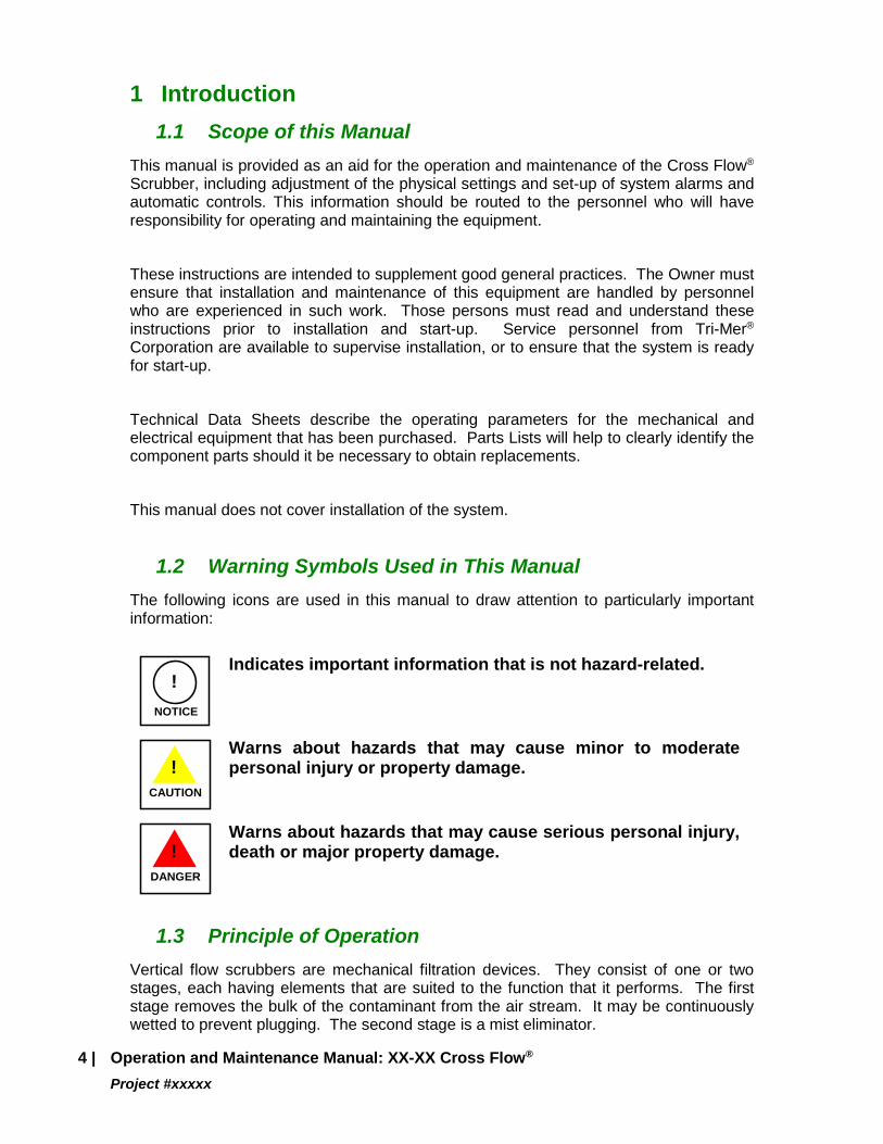
1.2 Warning Symbols Used in This Manual The following icons are used in this manual to draw attention to particularly important information:
NOTICE
!
Indicates important information that is not hazard-related.
CAUTION
!
Warns about hazards that may cause minor to moderate personal injury or property damage.
DANGER
!
Warns about hazards that may cause serious personal injury, death or major property damage.
1.3 Principle of Operation Vertical flow scrubbers are mechanical filtration devices. They consist of one or two stages, each having elements that are suited to the function that it performs. The first stage removes the bulk of the contaminant from the air stream. It may be continuously wetted to prevent plugging. The second stage is a mist eliminator.
4 | Operation and Maintenance Manual: XX-XX Cross Flow® Project #xxxxx
In a wet scrubber, water or scrubbing liquid is the media which removes pollutants from the air. When the water is recirculated, addition of fresh water is necessary to purge contaminants that accumulate and to replace evaporation losses. Fresh water may be added to the recycle reservoir either continuously or on a periodic basis.
1.4 Use of Fresh Water In a wet scrubber, fresh water must be added to the recycle loop for three reasons: to purge contaminants that are collected; to replace evaporation losses; and to flush mechanical seals on recycle pumps. Except in the latter case, the water does not usually have to be potable water.
In most cases, a continuous purge stream is created by adding water to the recycle loop to produce an overflow from the reservoir. If the scrubber recycle is operated in a batch or semi-batch mode, all or part of the scrubbing solution is released periodically and the volume is made up with fresh water and chemical. This process is done either manually or automatically. Level controls ensure that evaporation losses are replaced between releases. They consist of level switches and a solenoid-operated or motorized ball valve.
Operation and Maintenance Manual: XX-XX Cross Flow® | 5 Project #xxxxx
2 Safety 2.1 Hazards Inherent in the Equipment
Because of the potential hazards, it is important that the Owner install the system by the proper methods and with the proper materials for the intended service.
DANGER
!
Do not modify the equipment to override or defeat any of the safety mechanisms.
DANGER
!
Accessing the inside of the control cabinet with the power energized presents a high voltage exposure hazard. Only appropriately trained personnel should perform work in this mode.
2.1.1 Safety Accessories The responsibility for providing safety accessories and warning notices for equipment supplied by Tri-Mer® Corporation belongs to the installer and Owner of the equipment. The Owner must consider:
1. The location of the equipment. 2. The proximity of the equipment to employees and other persons and the
danger which this presents. 3. Requirements of applicable building codes and of the Occupational
Safety and Health Act.
2.1.2 In General: Wear safety glasses or goggles, gloves and protective clothing when working with
the chemicals or equipment which contains or transports them. Always assume that the system is under pressure. Use relief valves prior to
disassembly in order to reduce risk of injury or release of chemical. Do not add water to concentrated chemical solutions. Dilution is accomplished by
adding the chemical to water. Since much heat may be released by this action, take care to control the rate of addition to allow the heat to dissipate.
Do not add acids to solutions of hypochlorite, chlorite, or sulfide. Toxic vapors may be produced.
Do not mix strong acids with strong alkali. Heat of reaction could cause the solution to boil.
Do not mix strong oxidizing agents with organic chemicals. Explosive reactions may result.
When disposing of chemicals, treat them as hazardous wastes. Before discharging the contents of any reservoir, tank or piping assembly make sure
that the tank or utility that is to receive the discharge is properly prepared. Do not allow mixing of wastes that could react violently or with generation of toxic vapors.
6 | Operation and Maintenance Manual: XX-XX Cross Flow® Project #xxxxx
3 System Operation 3.1 System Overview
The purpose of these instructions is to aid in the installation and operation of equipment manufactured by Tri-Mer® Corporation. This information should be routed to the personnel who will have the responsibility for operating and maintaining this equipment.
These instructions are intended to supplement good general practices and are not intended to give detailed procedures. The Owner must ensure that installation and maintenance of this equipment are handled by personnel who are experienced in such work. Those persons must read and understand these instructions prior to installation and start-up. Service personnel from Tri-Mer® Corporation are available to supervise installation or to ensure that the system is ready for start-up.
Technical Data Sheets describe the operating parameters for the mechanical and electrical equipment that you have purchased. Parts Lists will help you to clearly identify the component parts and obtain replacements, if required.
3.2 Handling and Storage All equipment is thoroughly inspected prior to shipment in order to ensure proper operation of all components. It is shipped on skids or in crates to comply with trucking requirements. It is firmly secured and protected from the weather where required.
Inspect all equipment carefully when it is received. Note any damage on the carrier's bill of lading and immediately file a claim with the freight company. Keep a record of all equipment that has been received, including the date of receipt and details of inspection.
If you receive damaged equipment, contact Tri-Mer® Corporation for repair or replacement service. No material or equipment may be returned without Tri-Mer®’s prior written consent, which if granted, will contain shipping instructions that must be followed.
When unloading or moving equipment, take care to prevent injury to personnel or damage to the equipment.
If equipment is on a skid, use a fork lift with forks that span the full length of the skid.
When using a crane or similar lifting device, use a spreader bar. Apply only vertical force on lifting lugs. Use nylon straps or well-padded chains and cables which protect the equipment.
Open crates and unpack the equipment carefully. Plastic components may be damaged if not handled properly, especially at colder temperatures.
Consult prints, submittals and scope of supply when checking for completeness of delivered items.
Operation and Maintenance Manual: XX-XX Cross Flow® | 7 Project #xxxxx
If equipment must be stored before installation:
• Store it in the original container in a clean, dry, safe area.
• Protect from direct sunlight and from the elements. Use a reflective covering and arrange it in such a manner that air is allowed to circulate around the equipment in order to protect it from excessive heat and moisture.
• Cover flanges and couplings in order to prevent accumulation of dirt and moisture in the unit.
• Periodically rotate shafts on equipment like fans and pumps in order to protect the bearings.
3.3 Location of Equipment Locate equipment near service utilities such as water, sewer and electrical power. Make sure that the area is properly drained.
Do not crowd the equipment. Leave room for maintenance personnel to gain access.
Do not locate the equipment in a high-traffic area unless it is protected from collisions.
Mount equipment on a foundation which uniformly supports the base and has sufficient inertial mass to prevent problems due to vibration.
The foundation must be free of debris in order to prevent damage to the bottom of the base. It should extend beyond the outline of the base by at least twelve inches in order to accommodate anchoring.
The equipment must be level and plumb in order to prevent liquid distribution problems. Use shims where necessary to level it.
Poured concrete foundations are recommended. For equipment that is located above ground level, mounting on a rigid structural platform is required. Columns for suspended equipment must be cross-braced for support of live loads in order to prevent side sway.
3.4 Installation Guidelines The following are general guidelines for installation of this equipment.
Remove foreign material from within components before assembly.
Grout or shim under hold-down flanges or lugs to prevent applying excessive force to the vessel when anchor bolts are tightened.
8 | Operation and Maintenance Manual: XX-XX Cross Flow® Project #xxxxx
Do not apply excessive force when tightening bolts on any plastic flanges.
Do not tighten threaded plastic fittings more than 1-1/2 turns past hand-tight, since excessive force will damage threads. Use a strap wrench rather than a pipe wrench.
Place adequate guards around equipment with moving parts to protect personnel from injury.
When equipment is located outside, provisions must be made to protect it from freezing in cold weather.
3.4.1 Pipe and Fittings All piping connections should be made using good general practices for the materials involved. For pipe that is made from PVC or other thermoplastic materials, follow guidelines established by the Plastic Pipe Institute. Before continuous operation is attempted, all connections should be checked for leaks using water.
Use care in attaching all pipe connections to avoid excessive piping stresses, especially if the dust collector is of plastic construction. A flexible type of connection, such as hose connection, is generally preferred.
To prevent air becoming entrapped, pipe should rise in the direction of flow and be fitted with a vent valve at each high point. Pipe the vent to a drain.
Install a dirt trap and drain valve at every low point and the bottom of every riser to permit flushing. Pipe to a drain.
Drain fittings must be isolated from each other. Use a plumber's P-trap or submerge the end of each drain line. Either method will prevent air from flowing in the drain line. Such flows can cause by-passing, or they can interfere with proper drainage of the vessel.
Support and anchor all pipe and fittings in order to prevent damage to the equipment or to the pipe itself. Piping should never be supported by the flanges on equipment. It should be supported independently. This will prevent deformation or twisting of the equipment.
Heat trace pipe and fittings if necessary to prevent freezing.
3.4.2 Duct and Fittings For duct made from PVC or other thermoplastic materials, follow guidelines provided by the Sheet Metal and Air Conditioning Contractors' National Association (SMACNA) in their publication entitled Thermoplastic Duct Construction Manual.
Support and anchor all duct and components in order to prevent damage to the equipment or to the duct itself. Duct should never be supported by the flanges on
Operation and Maintenance Manual: XX-XX Cross Flow® | 9 Project #xxxxx
vessels or air moving equipment. It should be supported independently to prevent deformation or twisting of the equipment. Use a flexible connection whenever vibration isolators are used, and to minimize noise.
Avoid sudden changes in duct size. The included angle of an inlet transition should be 14 degrees or less. The outlet transition should not be more than 30 degrees. Elbows should be kept to a centerline radius of at least one and one-half duct diameters.
Branches entering a trunk line should be spaced, so that they do not enter directly opposite each other. They should enter at an angle of no greater than 45 degrees.
Place access doors in the ductwork just ahead of the vessel inlet and outlet connections. These doors should never be opened when the system is running to avoid equipment damage or personal injury.
Slope duct toward the equipment to prevent splash, spray or condensate from getting into the duct system.
Stack height should be sufficient to avoid introducing exhaust air into windows or air intakes. Use guy wires to brace against wind loads. Guy wires and hardware should be stainless steel or other corrosion-resistant material.
3.4.3 Electrical Equipment Electrical connections should be made only by a qualified electrician. Make sure that all electrical work is done in accordance with applicable codes.
Lock out the power source prior to any work being done. Be sure to follow the wiring diagram on the nameplate or terminal box of the electrical equipment.
Make sure that motors are wired for the correct supply voltage. Provide ample overload protection and other safety devices.
After electrical connections have been made, check the rotation the fan. Arrows show proper direction of rotation.
3.5 Assembly of the Scrubber System Install the scrubber as shown on the provided assembly drawing.
Connect the drain port to waste water using a butterfly valve for isolation.
Connect fresh water to the water fill and make up assembly.
Install the exhaust fan, inlet and outlet duct.
10 | Operation and Maintenance Manual: XX-XX Cross Flow® Project #xxxxx
3.6 Start Up and Operation Initial start-up and operation should be performed while the recycle tank is filled with water. Prior to start-up, remove all debris and clean strainers and spray nozzles.
Close the drain and fill the recirculation tank to its normal liquid level with water.
Calibrate pH, ORP or conductivity sensors if they have been provided. Adjust set-points. Follow the manufacturer's instructions.
Open the hand control valves to in the recycle loop.
Disable chemical metering pumps to prevent delivery of chemicals in response to signals from the analyzers that control composition of the scrubbing solution. This can be done by disconnecting electrical power or compressed air to the pumps.
Place the disconnect switch on the control panel into the "ON" position. Place the mode selector switches into the "AUTO" position.
Start operation by placing the system selector switch into the "ON" position.
Adjust valves in the pump discharge line to ensure that the desired flow rate is achieved.
Adjust dampers in the exhaust system to ensure that the desired ventilation is achieved. Use a velometer to check air flow rates.
Check for leaks and tighten any loose connections.
Measure and record operating amperage of each motor. Compare it to the nameplate rating to be sure that all motors are operating under safe load conditions.
Check for excessive vibration in the equipment.
Measure and record the pressure drop across each stage in the scrubber.
Test the "LOW FLOW" alarm by partially closing the valve on the pump discharge line to reduce the flow rate below the set-point.
Start fresh water flow to the recycle loop. Adjust make-up and/or blowdown rates to the required level using the rotameters on the side of the recycle tank. Make sure that the water level is being maintained.
Enable the chemical metering pumps and make sure that pH and ORP levels are controlled at their set-points.
Operation and Maintenance Manual: XX-XX Cross Flow® | 11 Project #xxxxx
The scrubber is ready to begin treating contaminated air.
3.7 Shut Down Stop operation by placing the system selector switch into the "OFF" position. Stop addition of make-up water by closing the hand valve in the plant water line.
If the system is to be down for an extended period (two to four weeks or longer) or cold weather, follow these additional steps:
• Drain all liquid from the system. Fill with clean water and circulate the water for five to ten minutes. Drain again to prevent freezing.
• Drain the pump housing, seal water lines and liquid traps, or fill with antifreeze if applicable.
• Lock out power to the control panel or motor control center to prevent accidents.
3.8 Maintaining Equipment Pressure Taps Several openings to the inside of the unit have been made in order that differential pressure may be measured. These holes may have to be cleaned periodically to prevent plugging. Use a small, blunt object (3/8” round rod or dowel) to remove debris that may have accumulated.
Daily Inspection
Measure and record pressure drop across the scrubber. Consult the factory if values are out of range (see Start Up and Operation).
Weekly Inspection
Check the fan for excessive vibration and excessive bearing temperature. Follow the manufacturer's instructions for maintenance of this equipment.
Semiannual Inspection
Inspect mist eliminator for accumulation of sludge, scale, or slime. Over a long period of time, it is not unusual for these elements to become fouled. The result is increased pressure drop and decreased efficiency. Clean or replace as necessary.
3.9 Pack Cleaning Procedure The packing should be cleaned before the pressure drop exceeds the clean-pack pressure drop by 50 percent or more or when visual inspection indicates that cleaning is necessary. It is usually possible to clean the unit by recirculating a cleaning solution through the vessel. Before attempting to clean the vessel, analyze the material causing the problem in order to determine its nature.
12 | Operation and Maintenance Manual: XX-XX Cross Flow® Project #xxxxx
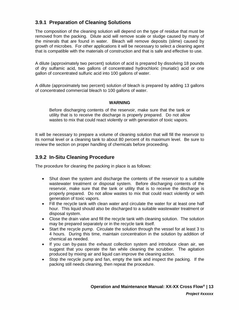
3.9.1 Preparation of Cleaning Solutions The composition of the cleaning solution will depend on the type of residue that must be removed from the packing. Dilute acid will remove scale or sludge caused by many of the minerals that are found in water. Bleach will remove deposits (slime) caused by growth of microbes. For other applications it will be necessary to select a cleaning agent that is compatible with the materials of construction and that is safe and effective to use.
A dilute (approximately two percent) solution of acid is prepared by dissolving 18 pounds of dry sulfamic acid, two gallons of concentrated hydrochloric (muriatic) acid or one gallon of concentrated sulfuric acid into 100 gallons of water.
A dillute (approximately two percent) solution of bleach is prepared by adding 13 gallons of concentrated commercial bleach to 100 gallons of water.
WARNING
Before discharging contents of the reservoir, make sure that the tank or utility that is to receive the discharge is properly prepared. Do not allow wastes to mix that could react violently or with generation of toxic vapors.
It will be necessary to prepare a volume of cleaning solution that will fill the reservoir to its normal level or a cleaning tank to about 80 percent of its maximum level. Be sure to review the section on proper handling of chemicals before proceeding.
3.9.2 In-Situ Cleaning Procedure The procedure for cleaning the packing in place is as follows:
• Shut down the system and discharge the contents of the reservoir to a suitable
wastewater treatment or disposal system. Before discharging contents of the reservoir, make sure that the tank or utility that is to receive the discharge is properly prepared. Do not allow wastes to mix that could react violently or with generation of toxic vapors.
• Fill the recycle tank with clean water and circulate the water for at least one half hour. This liquid should also be discharged to a suitable wastewater treatment or disposal system.
• Close the drain valve and fill the recycle tank with cleaning solution. The solution may be prepared separately or in the recycle tank itself.
• Start the recycle pump. Circulate the solution through the vessel for at least 3 to 4 hours. During this time, maintain concentration in the solution by addition of chemical as needed.
• If you can by-pass the exhaust collection system and introduce clean air, we suggest that you operate the fan while cleaning the scrubber. The agitation produced by mixing air and liquid can improve the cleaning action.
• Stop the recycle pump and fan, empty the tank and inspect the packing. If the packing still needs cleaning, then repeat the procedure.
Operation and Maintenance Manual: XX-XX Cross Flow® | 13 Project #xxxxx
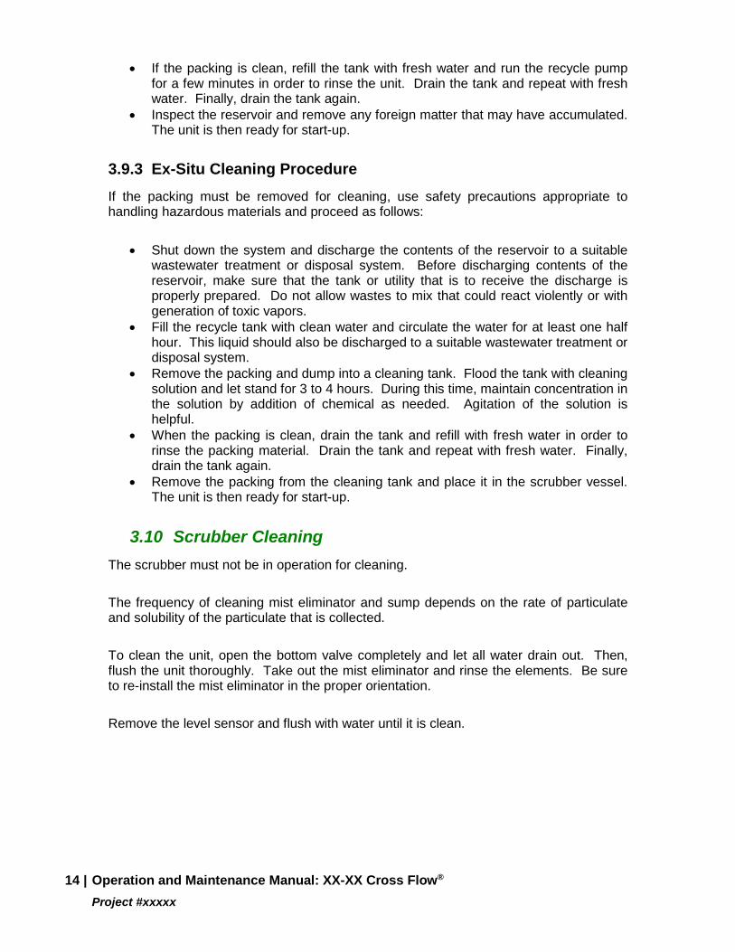
• If the packing is clean, refill the tank with fresh water and run the recycle pump for a few minutes in order to rinse the unit. Drain the tank and repeat with fresh water. Finally, drain the tank again.
• Inspect the reservoir and remove any foreign matter that may have accumulated. The unit is then ready for start-up.
3.9.3 Ex-Situ Cleaning Procedure If the packing must be removed for cleaning, use safety precautions appropriate to handling hazardous materials and proceed as follows:
• Shut down the system and discharge the contents of the reservoir to a suitable
wastewater treatment or disposal system. Before discharging contents of the reservoir, make sure that the tank or utility that is to receive the discharge is properly prepared. Do not allow wastes to mix that could react violently or with generation of toxic vapors.
• Fill the recycle tank with clean water and circulate the water for at least one half hour. This liquid should also be discharged to a suitable wastewater treatment or disposal system.
• Remove the packing and dump into a cleaning tank. Flood the tank with cleaning solution and let stand for 3 to 4 hours. During this time, maintain concentration in the solution by addition of chemical as needed. Agitation of the solution is helpful.
• When the packing is clean, drain the tank and refill with fresh water in order to rinse the packing material. Drain the tank and repeat with fresh water. Finally, drain the tank again.
• Remove the packing from the cleaning tank and place it in the scrubber vessel. The unit is then ready for start-up.
3.10 Scrubber Cleaning The scrubber must not be in operation for cleaning.
The frequency of cleaning mist eliminator and sump depends on the rate of particulate and solubility of the particulate that is collected.
To clean the unit, open the bottom valve completely and let all water drain out. Then, flush the unit thoroughly. Take out the mist eliminator and rinse the elements. Be sure to re-install the mist eliminator in the proper orientation.
Remove the level sensor and flush with water until it is clean.
14 | Operation and Maintenance Manual: XX-XX Cross Flow® Project #xxxxx
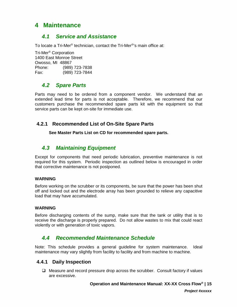
4 Maintenance
4.1 Service and Assistance To locate a Tri-Mer® technician, contact the Tri-Mer®’s main office at:
Tri-Mer® Corporation 1400 East Monroe Street Owosso, MI 48867 Phone: (989) 723-7838 Fax: (989) 723-7844
4.2 Spare Parts Parts may need to be ordered from a component vendor. We understand that an extended lead time for parts is not acceptable. Therefore, we recommend that our customers purchase the recommended spare parts kit with the equipment so that service parts can be kept on-site for immediate use.
4.2.1 Recommended List of On-Site Spare Parts See Master Parts List on CD for recommended spare parts.
4.3 Maintaining Equipment Except for components that need periodic lubrication, preventive maintenance is not required for this system. Periodic inspection as outlined below is encouraged in order that corrective maintenance is not postponed.
WARNING Before working on the scrubber or its components, be sure that the power has been shut off and locked out and the electrode array has been grounded to relieve any capacitive load that may have accumulated.
WARNING Before discharging contents of the sump, make sure that the tank or utility that is to receive the discharge is properly prepared. Do not allow wastes to mix that could react violently or with generation of toxic vapors.
4.4 Recommended Maintenance Schedule Note: This schedule provides a general guideline for system maintenance. Ideal maintenance may vary slightly from facility to facility and from machine to machine.
4.4.1 Daily Inspection Measure and record pressure drop across the scrubber. Consult factory if values
are excessive.
Operation and Maintenance Manual: XX-XX Cross Flow® | 15 Project #xxxxx

Check the rotation pattern of liquid within scrubber plates. There should be a smooth turning motion of liquid as seen through the window on the side of the scrubber.
4.4.2 Weekly Inspection Check the fan for excessive vibration and excessive bearing temperature. Follow
the manufacturer's instructions for maintenance of this equipment.
Check all piping components for leaks.
4.4.3 Monthly Inspection Perform all daily and weekly inspections plus the following.
Check fasteners and tighten as necessary.
Measure and record motor amperages. Consult the factory if these parameters exceed the nameplate value.
Inspect the pressure taps and associated fittings and tubing for wear or plugging. Clean or replace as necessary.
Inspect the sight gauge and fittings, and the equalization hole in the level control box. Clean or replace as necessary.
Lubricate bearings on the exhaust fan using a lithium-base NLGI, Grade II grease. Follow the manufacturer's instructions.
Check belts and drives for wear, and proper tension and alignment. Adjust or replace as necessary.
Inspect the fan impeller for wear or signs of fatigue.
4.4.4 Semiannual Inspection Perform all daily, weekly and monthly inspections plus the following.
Inspect mist pads and filter packs for accumulation of sludge, scale or slime. Over a long period of time, it is not unusual for the elements to become fouled. The result is increased pressure drop and decreased efficiency. Clean or replace as necessary.
4.4.5 Tri-Mer® Annual Service Agreement Tri-Mer® Corporation offers an annual service plan that includes two one-day visits per year for preventative maintenance. The scope of activities and terms of the Agreement will be provided upon request.
16 | Operation and Maintenance Manual: XX-XX Cross Flow® Project #xxxxx
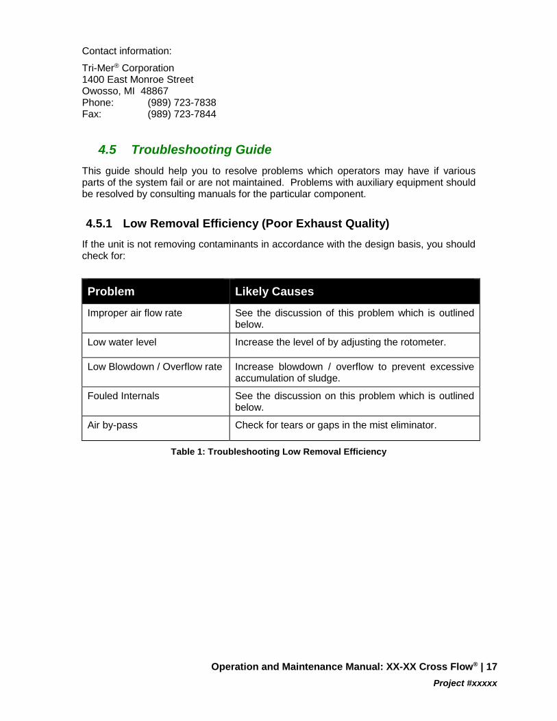
Contact information:
Tri-Mer® Corporation 1400 East Monroe Street Owosso, MI 48867 Phone: (989) 723-7838 Fax: (989) 723-7844
4.5 Troubleshooting Guide This guide should help you to resolve problems which operators may have if various parts of the system fail or are not maintained. Problems with auxiliary equipment should be resolved by consulting manuals for the particular component.
4.5.1 Low Removal Efficiency (Poor Exhaust Quality) If the unit is not removing contaminants in accordance with the design basis, you should check for:
Problem Likely Causes
Improper air flow rate See the discussion of this problem which is outlined below.
Low water level Increase the level of by adjusting the rotometer.
Low Blowdown / Overflow rate Increase blowdown / overflow to prevent excessive accumulation of sludge.
Fouled Internals See the discussion on this problem which is outlined below.
Air by-pass Check for tears or gaps in the mist eliminator.
Table 1: Troubleshooting Low Removal Efficiency
Operation and Maintenance Manual: XX-XX Cross Flow® | 17 Project #xxxxx
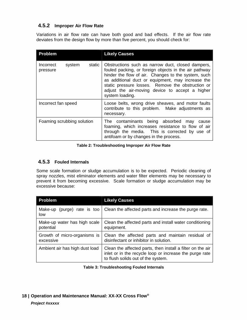
4.5.2 Improper Air Flow Rate
Variations in air flow rate can have both good and bad effects. If the air flow rate deviates from the design flow by more than five percent, you should check for:
Problem Likely Causes
Incorrect system static pressure
Obstructions such as narrow duct, closed dampers, fouled packing, or foreign objects in the air pathway hinder the flow of air. Changes to the system, such as additional duct or equipment, may increase the static pressure losses. Remove the obstruction or adjust the air-moving device to accept a higher system loading.
Incorrect fan speed Loose belts, wrong drive sheaves, and motor faults contribute to this problem. Make adjustments as necessary.
Foaming scrubbing solution The contaminants being absorbed may cause foaming, which increases resistance to flow of air through the media. This is corrected by use of antifoam or by changes in the process.
Table 2: Troubleshooting Improper Air Flow Rate
4.5.3 Fouled Internals
Some scale formation or sludge accumulation is to be expected. Periodic cleaning of spray nozzles, mist eliminator elements and water filter elements may be necessary to prevent it from becoming excessive. Scale formation or sludge accumulation may be excessive because:
Problem Likely Causes
Make-up (purge) rate is too low
Clean the affected parts and increase the purge rate.
Make-up water has high scale potential
Clean the affected parts and install water conditioning equipment.
Growth of micro-organisms is excessive
Clean the affected parts and maintain residual of disinfectant or inhibitor in solution.
Ambient air has high dust load Clean the affected parts, then install a filter on the air inlet or in the recycle loop or increase the purge rate to flush solids out of the system.
Table 3: Troubleshooting Fouled Internals
18 | Operation and Maintenance Manual: XX-XX Cross Flow® Project #xxxxx
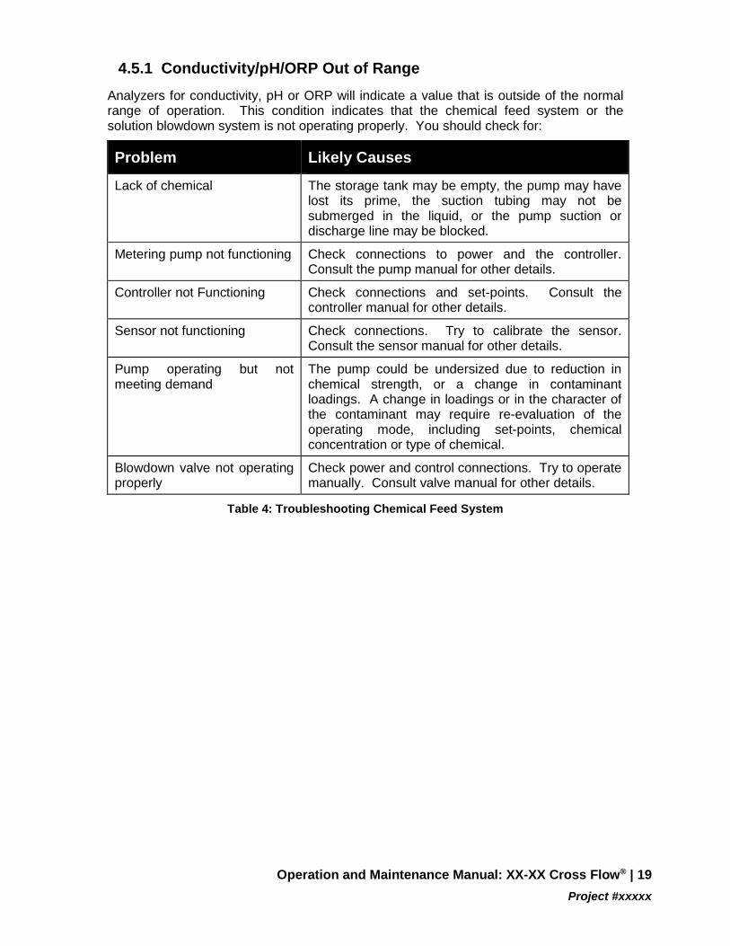
4.5.1 Conductivity/pH/ORP Out of Range Analyzers for conductivity, pH or ORP will indicate a value that is outside of the normal range of operation. This condition indicates that the chemical feed system or the solution blowdown system is not operating properly. You should check for:
Problem Likely Causes
Lack of chemical The storage tank may be empty, the pump may have lost its prime, the suction tubing may not be submerged in the liquid, or the pump suction or discharge line may be blocked.
Metering pump not functioning Check connections to power and the controller. Consult the pump manual for other details.
Controller not Functioning Check connections and set-points. Consult the controller manual for other details.
Sensor not functioning Check connections. Try to calibrate the sensor. Consult the sensor manual for other details.
Pump operating but not meeting demand
The pump could be undersized due to reduction in chemical strength, or a change in contaminant loadings. A change in loadings or in the character of the contaminant may require re-evaluation of the operating mode, including set-points, chemical concentration or type of chemical.
Blowdown valve not operating properly
Check power and control connections. Try to operate manually. Consult valve manual for other details.
Table 4: Troubleshooting Chemical Feed System
Operation and Maintenance Manual: XX-XX Cross Flow® | 19 Project #xxxxx
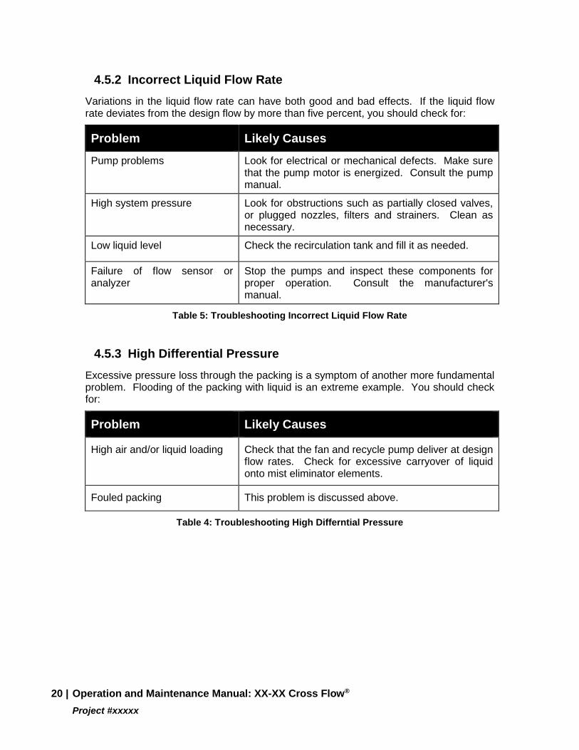
4.5.2 Incorrect Liquid Flow Rate Variations in the liquid flow rate can have both good and bad effects. If the liquid flow rate deviates from the design flow by more than five percent, you should check for:
Problem Likely Causes
Pump problems Look for electrical or mechanical defects. Make sure that the pump motor is energized. Consult the pump manual.
High system pressure Look for obstructions such as partially closed valves, or plugged nozzles, filters and strainers. Clean as necessary.
Low liquid level Check the recirculation tank and fill it as needed.
Failure of flow sensor or analyzer
Stop the pumps and inspect these components for proper operation. Consult the manufacturer's manual.
Table 5: Troubleshooting Incorrect Liquid Flow Rate
4.5.3 High Differential Pressure Excessive pressure loss through the packing is a symptom of another more fundamental problem. Flooding of the packing with liquid is an extreme example. You should check for:
Problem Likely Causes
High air and/or liquid loading Check that the fan and recycle pump deliver at design flow rates. Check for excessive carryover of liquid onto mist eliminator elements.
Fouled packing This problem is discussed above.
Table 4: Troubleshooting High Differntial Pressure
20 | Operation and Maintenance Manual: XX-XX Cross Flow® Project #xxxxx

Parts and Service For replacement parts or service, call
TRI-MER® ONE YEAR WARRANTY
TRI-MER® CORPORATION (hereinafter referred to as “Tri-Mer®”) warrants each of their products, manufactured by Tri-Mer®, against manufacturing defects within one (1) year from date of start-up or eighteen (18) months from shipment, whichever occurs first. During the first year, a product, or any part thereof deemed defective by the user, may, upon prior approval by Tri-Mer®, be returned to 1400 East Monroe Street, Owosso, Michigan 48867.
Tri-Mer®’s obligation under this warranty is limited to the furnishing of replacement parts (FOB your plant) determined to be defective. This warranty does not cover, and no allowance or payment will be made, for labor other expenses involved with the removal, repair, installation or replacement of any defective part or component, or any damages or other costs relating to such product. No warranty is made, and neither Tri-Mer® nor any of its employees or agents shall be liable to any owner or user of any product shipped by it for any consequential damages arising out of operation, possession, loss or use of any product or equipment in which it is installed. No warranty of fitness of a Tri-Mer® product for any particular purpose is made except where the application and method of use is approved in writing by Tri-Mer® in advance.
The Warranty of any equipment or component not manufactured by Tri-Mer®, but supplied to Tri-Mer® for use in its product, is limited to the specific warranty of the manufacturer involved. Tri-Mer® makes no warranty or guarantee of any nature with respect thereto.
The warranty contained herein is the only warranty applicable to any product sold or shipped by Tri-Mer®, and, except as set forth herein, all warranties (expressed or implied) are hereby disclaimed. No other agreements, guarantees or warranties, oral or written, are made or intended to be made by Tri-Mer®.
Operation and Maintenance Manual: XX-XX Cross Flow® | 21 Project #xxxxx