Cross Correlation Mitigation Techniques for Software GPS C ... · The first method, called Adaptive...
15
1 International Global Navigation Satellite Systems Society IGNSS Symposium 2007 The University of New South Wales, Sydney, Australia 4 – 6 December, 2007 Cross Correlation Mitigation Techniques for Software GPS C/A Code Receivers Eamonn P. Glennon SigNav Pty Ltd & School of Surveying & SIS, UNSW Phone: +61 2 6285 7900, Email: [email protected] Andrew G. Dempster School of Surveying & SIS, UNSW Email: [email protected] ABSTRACT The cross correlation properties of the 1023 chip Gold (C/A) codes can cause difficulties in scenarios where both strong and weak GPS signals need to be processed. Such cases are increasingly likely given the new applications of GPS, with examples being the processing of GPS signals in E911 cellular phone applications and the use of bistatic GPS as a remote sensing tool. This coupled with the increasing use of software-defined radio (software correlation) for either cost-saving or flexibility enhancing reasons have resulted in a need to mitigate cross correlations within such systems. This paper provides details on two techniques developed by the authors for the mitigation of GPS cross correlations, both of which have been tested and implemented within a software correlator that has been written in the C programming language. Details on the software correlator are also provided as the table lookup requirements for the correlator are smaller than those previously reported. Test results indicating the effectiveness of the algorithms are presented, with a comparison between the two methods being performed., The datasets containing cross correlations were obtained by capturing the output of a GPS radio front end chip attached to a hardware GPS simulator. KEYWORDS: cross correlation mitigation, near-far problem, GPS C/A code, software defined radio
Transcript of Cross Correlation Mitigation Techniques for Software GPS C ... · The first method, called Adaptive...

1
International Global Navigation Satellite Systems Society
IGNSS Symposium 2007
The University of New South Wales, Sydney, Australia 4 – 6 December, 2007
Cross Correlation Mitigation Techniques for Software GPS C/A Code Receivers
Eamonn P. Glennon SigNav Pty Ltd & School of Surveying & SIS, UNSW
Phone: +61 2 6285 7900, Email: [email protected] Andrew G. Dempster
School of Surveying & SIS, UNSW Email: [email protected]
ABSTRACT
The cross correlation properties of the 1023 chip Gold (C/A) codes can cause difficulties in scenarios where both strong and weak GPS signals need to be processed. Such cases are increasingly likely given the new applications of GPS, with examples being the processing of GPS signals in E911 cellular phone applications and the use of bistatic GPS as a remote sensing tool. This coupled with the increasing use of software-defined radio (software correlation) for either cost-saving or flexibility enhancing reasons have resulted in a need to mitigate cross correlations within such systems. This paper provides details on two techniques developed by the authors for the mitigation of GPS cross correlations, both of which have been tested and implemented within a software correlator that has been written in the C programming language. Details on the software correlator are also provided as the table lookup requirements for the correlator are smaller than those previously reported. Test results indicating the effectiveness of the algorithms are presented, with a comparison between the two methods being performed., The datasets containing cross correlations were obtained by capturing the output of a GPS radio front end chip attached to a hardware GPS simulator. KEYWORDS: cross correlation mitigation, near-far problem, GPS C/A code, software defined radio
2
1 INTRODUCTION
Many modern applications of GPS are limited by the cross correlation properties of the 1023 chip Gold code sequences used as the signal spreading codes. Such problems occur in any scenario in which weak GPS signals need to be tracked in the presence of other strong GPS signals and are a consequence of the 30 year heritage of the current signal structure. In extreme cases, the strong signals can completely mask any weaker signals thereby making acquisition of those signals almost impossible. Examples include application of pseudolites for GPS augmentation (Noronha, et al., 2006), GPS in E911 cellular phone applications and the use of bistatic GPS as a remote sensing tool. In less extreme cases, the strong signals simply degrade the accuracy of the weaker satellite observations, such as satellite carrier phase (Ganguly, et al., 2006, Zhu and van Graas, 2005). Although these problems are addressed by the longer codes of the new signal structures proposed for modernized GPS, the legacy signals already in place will continue to exist and as such, measures to overcome limitations of those signals are still required. Longer codes also present their own problems with respect to acquisition.
This paper describes two cross correlation mitigation (CCM) techniques developed by the authors. The first method, called Adaptive Orthogonization Using Constraints (AOUC) involves the use of non-standard despreading codes when despreading the weak signal satellite signals, where the new despreading codes are constructed by making minor changes to the standard codes based on simple constraints that depend on the other strong signal spreading codes. The second method, called Delayed Parallel Interference Cancellation (DPIC) is a post correlation subtractive method that is simple and effective at removing cross correlations and avoids the problem of needing to perform subtraction at intermediate frequency (IF) when the signal is highly quantised at typically one or two bits. The DPIC method also has the advantage of being able to cancel continuous wave (CW) interference, provided the CWI is being tracked.
Both of these methods have been implemented in a software correlator written in C. Validation of the techniques has been by using the software correlator to process test GPS datasets generated using a hardware GPS simulator and captured by recording the digital output from a GPS RF front end. The simulated signals were selected to represent extreme cases of multiple-access interference (MAI) and allow the effectiveness of both methods to be demonstrated.
2 C/A CODE SOFTWARE CORRELATION
The motivation for the work described in this paper stems from an initial requirement to observe and detect extremely weak multipath reflections separated by a large number of chips from the main correlation peak.In particular, the feasibility of using GPS as a bistatic-radar was to be investigated (Glennon, et al., 2005), although there are other applications.
This requirement presented a number of difficulties. Most commercially available GPS receivers are not designed for observing these signals and even if they were, the problem of cross correlations is rarely addressed. Given these difficulties and the fact that the feasibility of the original application was uncertain, software correlation represented an ideal process by which the original problem could be addressed. Not only is the correlation process entirely defined in software, but the development costs are extremely low and the ability to post-process results is more suited to a research program.
3
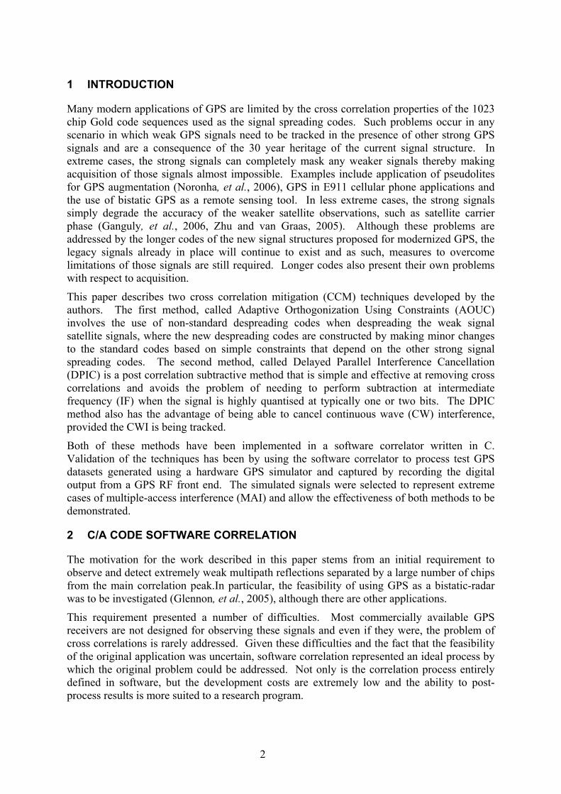
To implement the software receiver, the bitwise parallel technique of (Ledvina, et al., 2004) was selected as it is easy to implement and operates in the time-domain very much like a standard hardware GPS correlator. The correlation process requires that the two bit IF input be mixed with both replicated carrier and code and an integrate-and-dump performed every C/A code epoch. A truth table showing the values for the input IF, carrier DCO output and calculated product bits is given in Table 1, but does not include any despreading terms.
The output bits of P4, P3, P2, P1 and P0 are easily calculated using the following simple logic equations.
)()(0)(1
)(234
CmNOTANDMNOTPCmANDMNOTPCmNOTANDMP
CmANDMPCsXORSP
=====
(1)
If each of the above quantities is assigned a single word in the software receiver, then 16 or 32 bits may be processed in parallel. These equations apply to the down-conversion and do not include the despreading process which only affects the P4 sign bit term. As such, different correlator channel fingers each with a slightly different despreading code may be used to update the P4 quantity only. The “integrate and dump” process is also easily performed by counting the number of bits for the different weightings (6, 3, 2 and 1) and then accumulating those bits while taking into account the value of the sign quantity P4 after despreading. The despreading process is performed by an exclusive-or between P4 and the despreading code.
One substantial difference in the basic GPS software correlator implemented here concerns the way in which the pre-computed lookup tables used to generate the carrier NCO output and
Raw IFin Carrier NCO OP
± 6 3 2 1
IFin S M C Cs Cm OP P4 P3 P2 P1 P0-3 1 1 -2 1 1 6 0 1 0 0 0 -3 1 1 -1 1 0 3 0 0 1 0 0 -3 1 1 1 0 0 -3 1 0 1 0 0 -3 1 1 2 0 1 -6 1 1 0 0 0 -1 1 0 -2 1 1 2 0 0 0 1 0 -1 1 0 -1 1 0 1 0 0 0 0 1 -1 1 0 1 0 1 -1 1 0 0 0 1 -1 1 0 2 0 1 -2 1 0 0 1 0 1 0 0 -2 1 1 -2 1 0 0 1 0 1 0 0 -1 1 0 -1 1 0 0 0 1 1 0 0 1 0 1 1 0 0 0 0 1 1 0 0 2 0 1 2 0 0 0 1 0 3 0 1 -2 1 1 -6 1 1 0 0 0 3 0 1 -1 1 0 -3 1 0 1 0 0 3 0 1 1 0 1 3 0 0 1 0 0 3 0 1 2 0 1 6 0 1 0 0 0
Table 1: Software Correlation Truth Table
4
PRN codes were implemented because the original Ledvina method required a substantial amount of memory. In particular, the PRN codes for each SV require 720 Bytes (B) (5714 one-bit samples/CA code epoch) while carrier lookups for Doppler frequencies in the range of -10 kHz to +10 kHz consume 323 kB. Storage of PRN code samples consumes 30 MB total although it is stated that this can be reduced to 960 kB if PRN codes with fractional code phases are stored and then simply shifted to align with the incoming signal.
These memory requirements can be reduced substantially using the following technique. Firstly, the PRN sequence for each satellite is stored in a 128 byte array, where the table can be initialised when the channel is initialised. When the PRN code samples for a 16-sample (2.8 us) batch are required, the current chip and sub-chip are used to index into the PRN table and the chips shifted so that the required chips match the chips in the input 16-bit sample buffer. Since each 16-sample batch represents 2.8 us which is less than 3 chips, a set of tables containing a mapping of all the chip combinations in the input buffer into sampled chip combinations with different initial code phases may be used. This table is also small and consists of 16 32-bit sampled PRN sequences (allowing for 5.2 chips) for up to 64 different initial code phases and calculated for a nominal code Doppler of 0. This second table may used for all satellites as the code is quite insensitive to Doppler frequency. In the case of replicated carrier frequency each channel is associated with a table containing 2-bit carrier signal at a particular Doppler frequency for 64 different carrier phases, with the table being recalculated when the Doppler error is becomes excessive. This equates to required storage of 64×2 16-bit words per channel. It is clear that this two stage lookup arrangement for PRN samples and single stage on-the-fly arrangement for carrier samples is much more efficient in terms of memory utilization, albeit at a cost of a slightly more complicated lookup process.
The software correlator was written in C and called from a wrapper function that implemented both a crude tracker for satellites as well as a search-engine function allowing correlations across all code phases for a particular Doppler frequency to be displayed. The functions were set up so that they could be called from Matlab using the MEX interface thereby allowing the plotting capabilities of Matlab to be harnessed whilst still gaining all the advantages of a C compiled program. Debugging of the C program was conducted within the Borland Builder Integrated Development Environment (IDE).
3 ADAPTIVE ORTHOGONIZATION USING CONSTRAINTS
3.1 Concept and Theory
Adaptive Orthogonalization Using Constraints (AOUC) represents the first of the two cross correlation mitigation (CCM) methods that were developed. The key to understanding this mitigation technique is to recall that cross-correlation (CC) interference is a consequence of an unbalanced cross correlation sequence, where the cross correlation sequence is defined as element by element product between the strong and weak spreading sequences. As described by (Spilker, 1996), for the GPS C/A code (1023 element Gold codes sequences) of 1 and -1, the maximum cross correlations of -63 and +65 both occur with probabilities of 1/8, while the typical cross correlation value of -1 occurs with a probability of 6/8. This indicates that in the case of zero Doppler frequency between strong and weak signals, most relative code phases will exhibit very low CC interference, although the remaining 25% of cases this will be substantially larger. In these situations the CC are caused by an imbalance of only 64 out of 1023 chips and as such, modification of as few as 32 chips in the weak signal PRN code can rebalance the CC sequence thereby completely eliminating the problem. Details of this method were first published in (Glennon and Dempster, 2005) and is currently patent pending (Dempster and Glennon, 2007).

5
Implementation of this idea was significantly more difficult than initially anticipated, with relative carrier Doppler effects, the presence of both in-phase (I) and quadrature (Q) channels and the scenario of multiple strong satellites causing problems. To understand these difficulties, consider the theoretical analysis of the I and Q integrate-and-dump outputs of a standard GPS correlator (Van Dierendonck, et al., 2002).
∑ ∫≠=
+
++
=
N
wss
TMk
Tkws
s
w
www
w
w dttTP
kkDPkQkI
,1
)(
)()(sincos
)()()( gη
φφ
(2)
+∆+∆
−−=)2sin()2cos(
)()()()(wskwskd
wskwskdwwsks
Dwsksws tf
tftctctDt
φπφπ
ττg
In equation (2), the first term represents the desired weak signal autocorrelation terms and the last term the sum of the CC components. The s subscript refers to the strong signal space vehicle (SV) numbers, the w subscript refers to the weak signal SV numbers, N is the number of visible SVs, η is the noise, k the output integrate & dump sample number, cn(t), Dn(t) and Pn are the spreading code, data-bit value and signal power for SV n respectively, while ∆fdwsk and ∆φwsk are the relative Doppler frequency and phase differences between the weak and strong signals respectively for output sample k. The CC terms represent the projection of each strong signal onto the vector space of the weak signal and since these codes are not orthogonal, this projection is typically non-zero resulting in the unwanted MAI.
The idea with AOUC is rather than using a despreading code cw(t) that is exactly matched to the weak signal, a slightly different despreading code ĉw(t) that is close to cw(t) is used. This ĉw(t) has the effect of driving each CC term to (near) zero. The required constraint is expressed in the formula below.
∫+
=
+∆+∆
−−TMk
Tk kwskwsd
kwskwsdwkwss
Dwsks dt
tftf
ttctD)(
0)2sin()2cos(
)(c)()(φπφπ
ττ
To see how ĉw may be obtained, consider first the CC without regard to relative Doppler carrier terms, data-bit modulation, inphase/quadrature channels and realistic sampling. Here the strong and weak pseudo-random sequences cw(i) and cs(i) are both of length I0 and the cross correlation between the two sequences CCw.s may be calculated as
( ) ( ) ( )
( ) ( )
( )0
1
ICCCC
iccjCC
icicicc
swsw
j
iswsw
swsw
⋅⋅
=⋅⋅
⋅
=
=
⋅=
∑ (3)
where i & j are chip indices, i, j∈{1…I0}, I0 refers to the number of chips in the spreading code and has a value of 1023 for GPS C/A codes, a w subscript refers to a weak signal SV and an s subscript refers to strong signal SV number. A weak signal is any signal that has a power level less than the cross correlation threshold of 24 dB below the strong signal. CCw.s(j) denotes a partial CC and is useful later.
Clearly, the non-zero cross correlation CCw.s occurs because the CC sequence ccw.s(i) is unbalanced, which means the number of 1’s is different to the number of -1’s. This immediately suggests a method for mitigation of this problem, namely modifying the weak PRN cw to some other code ĉw so that the new cross correlation sequence ccw.s is balanced. ĉw can be constructed relatively easily as described in the following sections, with two types of logic being required depending on whether single or multiple strong signals are present.

6
The constructed despreading codes are only applicable given the particular relative code phases of the other transmitting codes and continual adjustment of the orthogonalization process is therefore required as the relative code phases vary due to satellite Doppler or user motion. This differs from an ideal spreading code which has low cross correlations with other codes at all relative code phases.
It should also be apparent that CCM requires the regeneration of the strong signals in both code and carrier phase, which implies that these strong signals are being tracked in one of the tracking channels. These constructed pure strong signals are correlated with the weak PRN codes to predict the resulting pure cross correlation interference which is then used to evaluate the amount of mitigation required and the effectiveness of any mitigation so far applied.
3.2 Single Strong Signal Mitigation
The scenario in which only a single strong signal is present represents the easier of the two cases. To solve this problem, it is first necessary to find a set of a set of chip indices CI for the cross correlation sequence ccw.s where the sign of the chip matches the sign of the final cross correlation CCw.s(N). The new orthogonalized code ĉw is then constructed by changing the sign of floor(|CCw.s/2|) chips of cw, where the chip indices are taken from the set CI. Mathematically this can be stated using set notation, where |F| denotes the cardinality (size) of the set F and boldface denotes a set.
{ }( ) ( )( ){ }
( ){ }( )
( ) ( )( )
∈∈−
=
−=
=
=∈=
⊂===∈≤≤=
FF
FIF
CI
FCIFICI
ΖI
iiciic
ic
ofelementsICCfloorAny
ICCflooriICCsignicci
IndicesChipValidAlliIii
w
ww
sw
sw
swsw
::
ˆ
2/
2/::
&1:
0.
0.
0..
0
Since the PRN codes are single bit quantities, the product ccw,s may be calculated with an exclusive-or operation between cw and cs while the CC prediction CCw,s(I0) is performed by accumulating the ccw,s terms with a counter. Each inversion of a cw chip (chip-flip) is matched by a reduction in the predicted CC magnitude by 2, with the process being terminated when the predicted CC magnitude is reduced to an acceptable level.
A geometric interpretation is to consider a plot of partial cross correlation CCw,s(i) versus chip number i. For a CC to exist, the value of CCw,s(I0) must be non-zero. The CCM scheme is to locate segments where the gradient of CCw,s(i) matches the final CC sign and then to invert some of the cw(i) chips thereby reversing the gradient for a small segment and thereby reducing the value of CCw,s(I0).
3.3 Multiple Strong Signal Mitigation
The single strong signal algorithm cannot be used when multiple strong signals are present because changes made to improve the cross correlation with respect to one of the strong signals typically degrade the cross correlation with respect to the other strong signals. Nonetheless, if the PRN codes of all the other strong signals are taken into account, it is still possible to apply the concepts of the single strong signal case to multiple strong-signal scenarios. If the single strong signal algorithm is characterised by reversing the gradient of CCw,m (m indicates the strong signal being mitigated) when the gradient is moving in the

7
wrong direction, then the multiple strong signal case may be characterised as the single strong signal case but constrained to locations where the gradients of the other strong signals CCw, m’ are zero (where m’ is any strong signal not equal to m). Since modifications to cw results in changes to all of the CCw,s, this constraint ensures that cross correlations with other strong signals are not degraded as the CC for each strong signal m is reduced.
The process can be expressed mathematically using the same notation as before. { }{ }
( ){ }( ){ }
{ }
( ) ( )( ){ }
( ){ }( )
( ){ }
( ) ( ){ }
( ) ( )( )
∈∈−
=
−−=
∈≠=∪=
=∈=
=
=∈=
∩=
∩===
==
==
=−=
=∈=⊂∈∈<=⊂∈∈>=
=≤<==∈≤≤=
∈
∈
FF
XIFIFIXI
FFFFCIF
CI
FCIFLCICIHCICI
CI
LLLL
HHHHMSM
SMIISLIISH
SΖI
HL
LLL
H
HHH
MmL
MmH
m
mMmM
mMmM
s
s
iiciic
ic
iicici
ICCfloorii
ofelementsICCfloorAny
ICCfloorii
ICCsignicci
MitigatedBeingNotSignalsRemainingMitigatedBeingSignalStrongmm
isicciisicci
SignalsStrongOfNoisSPRNsSignalStrongSss
IndicesChipValidAlliIii
w
ww
ww
mw
mw
mw
mwmw
Mm
Mm
sw
sw
::
ˆ
&ˆ:
4/&:
4/
4/&:
:
:&&0:&&0:
,1:&1:
0.
0.
0.
0..
.
.
0
0
0
I
I
3.4 Relative Doppler Carrier Effects
In the discussions thus far, the algorithm has been presented assuming that the relative Doppler carrier (RDC) frequency difference between the strong and weak signals is zero Hertz. In reality this is rarely true and as such it is essential that this be properly accounted for. Firstly, since the RDC phase is different between the I and Q channels, separate mitigation is required for the I & Q channels. Equally important is that since the typical satellite Doppler frequency is in the range of ±5 kHz, the RDC frequency difference between two different satellites could be anywhere within the range of ±10 kHz amounting to up to 10 cycles of RDC per C/A code epoch. This has the effect of modulating the strong signal PRN code by the RDC thereby effectively changing the strong signal PRN code with regard to cross correlation effects.
For the algorithms presented to be applicable while still taking RDC into account, it is necessary to make the strong signal PRN code appear as though it is at zero Hertz frequency offset. This can be done by decomposing the RDC term mix(φ(i)) into the product of a sign and magnitude component, where the mix term is either cosine or sine for the I or Q channel channels respectively.
8
( ) ( ) ( ) ( )( ) ( ) ( )( ) ( ))()(sgn
)(imiximixicic
imixicicicc
sNw
sNwsNwRDC
φφ
φ
⋅⋅⋅=
⋅⋅=⋅
Selection of the chips to invert is then made assuming that that |mix(φ(i))| is one, although the effect of any changes are weighted by |mix(φ(i))|. Care needs to be taken if making changes when |mix(φ(i))| is close to zero because these changes have little impact on the final cross correlation and the are subject to quantisation errors when calculating the effect of those changes. For this reason, it is recommended that a dead zone (DZ) near 0 be applied to ensure that ineffective changes are not applied.
3.5 Other Remarks on AOUC
AOUC is a novel CCM technique that offers a number of advantages over other techniques for dealing with GPS C/A code MAI. Compared to standard subspace projection (Thomas, et al., 2004), the technique is far simpler to implement and can even be implemented in hardware, having already been implemented and tested in a software receiver. However, it does have the disadvantage that as the number of strong signals increases, it becomes more difficult to satisfy the required constraints resulting in failure if more than three strong signals are present. An increase to four strong signals is possible if two bit despreading codes are employed although this comes at a cost of increased noise susceptibility. The technique also results in a small loss of sensitivity due to the orthogonalization loss, although this loss is typically significantly less than the gains to be had by removal of the CC interference. For N strong signals, the orthogonalization loss in dB is given by:
−
−=1023
)641023(log20 10NLothog
Further details on AOUC may be found in (Glennon and Dempster, 2006).
An additional advantage to be gained from AOUC is that the effectiveness of the mitigation does not depend on the accuracy of the amplitude estimate. This is not the case with purely subtractive mitigation schemes, such as Successive Interference Cancellation (SIC) (Madhani, et al., 2003) or the Delayed Parallel Interference Cancellation (DPIC). In any subtractive scheme, any amplitude estimate error results in a residual strong signal which causes residual cross correlation noise. In much the same way, the method is also effective even if the strong signal data-bits are completely ignored with only 1 in 20 C/A code epochs being affected and only during a data-bit transition. In fact, the AOUC results presented here do ignore navigation message data-bits, even though better results may be achievable were these to be taken into account.
Experimental results showing the performance of AOUC are discussed in Section 5 and shown in Figures 3 – 6.
4 DELAYED PARALLEL INTERFERENCE CANCELLATION
4.1 Concept and Theory
Following the development of the AOUC CCM method, a comparison with a more conventional CCM technique was considered to be useful. A number of conventional techniques are available for this purpose (Glennon and Dempster, 2004), with the SIC method described by (Madhani, et al., 2003) getting particular consideration having actually been applied to real GPS signals. However, following further consideration of the SIC technique and not wanting to deal with the problem of performing subtraction very small signals from a

9
two-bit IF input representation, it was realised that a better alternative existed. This improvement was subsequently developed into the Delayed Parallel Interference Cancellation (DPIC) technique (Glennon, et al., 2006).
To see how DPIC was derived from SIC, consider the basic architecture of the SIC system as shown in Figure 1. Each serial stage in the process is used to process weaker signals in which strong signals have already been removed by subtraction.
Figure 2 top shows a single stage of SIC where the integrate-and-dump outputs are separated from the downconvert-and-despread process while Figure 2 bottom shows an equivalent reorganisation exploiting the linearity of the downconvert-and-despread block. From the equivalent block diagram, it can be seen that the same results as the standard SIC may be achieved by processing both the reconstructed strong signal IF and the original input signal IF in separate correlators and then performing the subtraction at the end, provided that the code and carrier NCOs perform identical operations at all times. This is easily achieved if the reconstructed correlator is slaved to the weak signal correlator. In this architecture, the final subtraction is generally performed in software since the reconstructed strong signal IF will usually not be properly scaled (assuming a simple reconstruction process) and needs to be adjusted based on the measured amplitude of the strong signal. Clearly this process can be performed for multiple strong signals, with the subtraction being delayed until the sample dumps have taken place. The software can then determine which strong signals are sufficiently strong to cause a problem and limit the mitigation to only those satellites likely to cause difficulties, with all of the CC’s being removed simultaneously (in parallel).
ConventionalDetector
RegenerateInterference
Frequency,Amplitude& PhaseInput Signal r(t)
Σ
Regenerated Signal
s1(t)
r1(t) Stage 2
Stage1
r2(t)
+
-
RegenerateDelay
r(t-τ)
Figure 1: Successive Interference Cancellation (SIC)
I Integrate & DumpΣ+
-
ReconstructedStrong Signal IF
Raw InputSignal IF
Downconvert&
Despread Q Integrate & DumpCode & CarrierDCO Controls
ReconstructedStrong Signal IF
Downconvert&
Despread
Raw InputSignal IF
Σ-
+
I Reconstructed Integrate & Dump
Q Reconstructed Integrate & Dump
Downconvert&
Despread
I Input Signal Integrate & Dump
Q Input Signal Integrate & Dump Σ
+
-Q Integrate &
Dump
I Integrate &Dump
Code & CarrierDCO Controls
(same to both blocks)
Figure 2: Standard Processing of Differenced IF (top) and Alternate Processing (bottom)

10
As with all subtractive type CCM, there is a requirement to properly deal with the modulation caused by the presence of GPS navigation message data. Failure to correctly account for the data-bit sign results in addition instead of subtraction and (unlike AOUC) affects all 20 C/A code epochs in a bit thereby making the MAI worse. Taking the strong signal data-bits into account is straightforward, requiring simply that the partial strong signal in-phase channel sign be multiplied with the reconstructed signal. Maintaining a hardware data-bit accumulator for the strong signals is one way of doing this.
DPIC offers a number of advantages over standard SIC, such as avoiding the need to subtract a strong signal that is buried below the noise from an essentially noise like IF input signal, where both signals are represented as 2-bit sign/magnitude. There is no requirement to continually adjust the order in which the strong signals are removed, as is the case for SIC, as the subtraction is only performed at the end when all of the information is available. The software overhead is low, requiring simply that all associated slave I & Q dump values be scaled by the matching strong signal I & Q dump values before being subtracted from the weak signal I & Q dumps.
A disadvantage of the method is that as the number of strong signals increases, the number of pairs of cross correlations also increases thereby increasing the number of slave correlators that are required. If there are Ns strong signals and Nw weak signals, then the total number of correlator channels Nc required to detect all of the signals are
Nc = Ns + Nw + Ns×Nw
Nv = Ns + Nw
where Nv is the total number of visible signals, which in the case of GPS is usually constrained to be less than 12. Hence in the case of GPS, a total of 48 channels are required if a maximum of 12 satellites are to be processed. However, in this case the slave channels are not required to contain the full complexity of a standard correlator channel since the code and carrier NCO as well as code generators can be taken from existing master channels. This means that the additional hardware complexity is not excessive. Modernised GNSS signals in fact require a high correlator count to ensure similar acquisition times to legacy signals.
4.2 Similarities with Other Methods
One technique that is similar to DPIC is the CCM method of (Norman and Cahn, 2004). A close examination of the Norman method indicates that unlike DPIC, approximations in the estimation of the CCs are performed by simply scaling the calculated DC (zero Doppler frequency difference CC value) by a factor that depends on the frequency difference between the strong and weak signals. Unfortunately there are many instances in which this approximation will be inadequate and in those cases, the cancellation will not be successful.
Mathematically, it can be shown that DPIC is very similar to a well studied MAI mitigation technique known as the ‘Decorrelating Detector’(Moshavi, 1996). Details describing the similarity are described in (Glennon, et al., 2006), with both methods involving post-correlation removal of the CC interference. However, DPIC does not require inversion of a matrix of normalised cross correlation values and uses instead a simple approximation.
Experimental results showing the performance of DPIC are discussed in the next section and shown in Figures 3 – 7.

11
5 CCM EXPERIMENTAL RESULTS
Validation of both techniques was performed using the software correlator described in Section 2, but modified to perform either AOUC or DPIC as a compile time switch. Generation of data-sets containing severe CCs was performed with a six channel WelNavigate GS700 GPS simulator using a test mode in which each of the channels could be configured manually with a particular satellite, carrier frequency and navigation data. The simulator output was connected to a modified SigNav MG5001 GPS receiver, where the modifications involved tapping into the sign/magnitude IF output and the 40/7 MHz input sample clock for the Zarlink GP2015 front end via a custom interface board. The data was captured using a National Instruments NI6534 PCI digital IO card and logged to disk for later post-processing. Table 2 provides parameters for the collected datasets, where it should be noted that in all cases, the strong signals are separated from the weak signals by frequency differences that are multiples of 1 kHz. This represents the worst possible case.
To allow a quantitative comparison between the two techniques, a Detectability Factor (DF) analogous to a signal to noise ratio (SNR) has been defined, where:
)())(( 2
NoiseVarNoiseMeanPDF −
=
P is the amplitude of the ‘true’ signal (generally the peak when AOUC or DPIC has been used), Mean(Noise) is the mean noise floor and Var(Noise) is the noise floor variance excluding the peak.
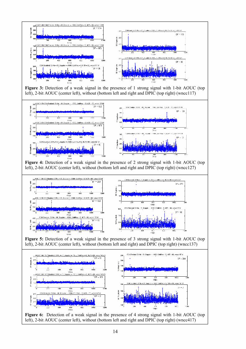
Figures 3 to 6 show the results of running the test datasets 1 to 4 comprising 1 to 4 strong signal satellites respectively. Each set of results shows a ‘search-engine’ style output in which correlations across all 1023 code phases are performed using a 5 ms coherent integration and 80 non-coherent rounds of additional accumulation. This amounts of 320 ms of integration in all cases. A summary of the results is given in Table 3.
Test / Dataset SV SNR (dB-Hz)
Doppler (Hz)
Code (Chips)
Data Modulation
31 ~50 -2500 - Y 1, WelNav wncc117 1 ~27 -1500 - N
31 ~50 -2500 - Y 30 ~50 -2500 - Y
2, WelNav wncc127
1 ~27 -1500 - N 31 ~50 -2500 - Y 30 ~50 -2500 - Y 29 ~50 -500 - Y
3, WelNav wncc137
1 ~27 -1500 - N 31 ~50 -2500 - Y 30 ~50 -2500 - Y 29 ~50 -500 - Y 28 ~50 -3500 - Y
4, WelNav wncc147
1 ~27 -1500 - N 31 ~50 -2600 - N CW ~55 ~600 - n/a
5, WelNav wncwicc108
1 ~27 -1600 - N Table 2: CCM Dataset test conditions
12
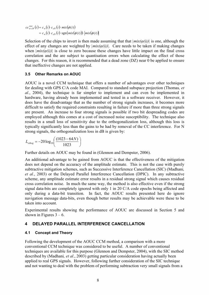
The results show that when no mitigation is performed, the weak signal is never detected. For 1-bit AOUC, the signal is detected for cases in which the number of strong signals is less than 4, but fails when there are 4 strong signals due to a failure to find sufficient instances where the required constraints are met. The failure with 4 strong signals can be improved if 2-bit AOUC is used, but this makes the process more susceptible to noise as can be seen from the reduced values for DF. The DPIC process gave the best results of the two methods and was able to detect the weak signal in all cases. Some of the better performance of DPIC may be attributable to the lack of orthogonalization losses and that the AOUC implemented here ignores the navigation message data-bits in the strong signals resulting in no mitigation at some points within the process.
One advantage that DPIC has over AOUC is that DPIC is also able to cancel some forms of continuous wave interference (CWI). During the collection of the datasets, it was discovered that the GS700 simulator has a ‘feature’ whereby setting the satellite number to zero results in no spreading code being applied thereby resulting in the output of CW only. When the software correlator was modified to track the CW, it was possible to subtract the effects of the CWI on the weak signal away resulting in an ability to detect the weak signal. Figure 7 shows the results of processing a dataset containing CWI with a standard correlator, a DPIC correlator cancelling only the strong signal from space vehicle (SV) 31 and a DPIC correlator cancelling both the strong signal from SV31 and the CWI. It is clear that both the CWI and the strong signal impact on the detectability of the weak signal and require cancellation.
6 CONCLUSIONS
In this paper, two GPS C/A code cross correlation mitigation techniques developed by the authors have been presented and compared. Adaptive Orthogonalization Using Constraints (AOUC) is a suboptimal subspace projection technique that is easily implemented in both a software and hardware correlator, while Delayed Parallel Interference Cancellation (DPIC) is a subtractive method that is similar to the ‘Decorrelating Detector’. Both methods allow the detection of otherwise weak undetectable signals in the presence of multiple access interference, with the process being validated using a software GPS receiver processing real GPS signals generated with a hardware GPS simulator.
ACKNOWLEDGEMENTS:
This work was supported by the Australian Government Department of Industry, Tourism and Resources under the START Program. This research was also supported by the Australian Research Council Discovery Project DP0556848.
Test Strong Signals
No CCM DF 1-Bit AOUC DF
2-Bit AOUC DF
DPIC DF
wncc117 1 38 174 166 198 wncc127 2 10 122 103 133 wncc137 3 10 208 160 279 wncc147 4 2 51 (poor) 101 204 Table 3: Measured Detectability Factors using No Mitigation, One Bit AOUC,
Two Bit AOUC and DPIC

13
REFERENCES
Dempster, AG and Glennon, EP (2007), Apparatus and Method for the Mitigation of Cross Correlation in GPS System, United States of America Patent Application Number 20070058696
Ganguly, S, Bhatia, N, Jovancevic, A, Brown, A, Kirchner, M, Saxena, D, Noronha, J and Zigic, S (2006), Self-Calibrating Receivers for Precision Phase Observations, Proceedings of the 19'th International Technical Meeting of the Satellite Division of the Institute of Navigation, 2788 - 2797
Glennon, EP, Bryant, RC and Dempster, AG (2006), Delayed Parallel Interference Cancellation for GPS C/A Code Receivers,12'th IAIN World Congress and 2006 International Symposium on GPS/GNSS,
Glennon, EP and Dempster, AG (2004), A Review of GPS Cross Correlation Mitigation Techniques, The 2004 International Symposium on GNSS/GPS,
Glennon, EP and Dempster, AG (2005), A Novel GPS Cross Correlation Mitigation Technique, ION-GNSS 2005,
Glennon, EP and Dempster, AG (2006), Cross Correlation Mitigation by Adaptive Orthogonalization Using Constraints - New Results.,19th Int. Tech. Meeting of the Satellite Division of the U.S. Inst. of Navigation, 1811-1820
Glennon, EP, Dempster, AG and Rizos, CR (2005), Feasibility of Air Target Detection using GPS as a Bistatic Radar, International Symposium on GPS/GNSS,
Ledvina, BM, Psiaki, ML, Powell, SP and Kintner, PM (2004), Bit-wise parallel algorithms for efficient software correlation applied to a GPS software receiver, Wireless Communications, IEEE Transactions on
Madhani, PH, Axelrad, P, Krumvieda, K and Thomas, JK (2003), Application of successive interference cancellation to the GPS pseudolite near-far problem, Aerospace and Electronic Systems, IEEE Transactions on
Moshavi, S (1996), Multi-user detection for DS-CDMA communications, Communications Magazine, IEEE
Norman, CP and Cahn, CR (2004), Strong Signal Cancellation to Enhance Processing of Weak Spread Spectrum Signal, United States of America Patent 6,707,843
Noronha, J, Jovancevic, A, Bhatia, N, Sirpatil, B, Kirchner, M and Saxena, D (2006), Field Test Results of a Flexible Pseudolite Based Navigation System, Proceedings of the 19'th International Technical Meeting of the Satellite Division of the Institute of Navigation, 102 - 113
Spilker, JJ (1996), Signal Structure and Theoretical Performance, American Institute for Aeronautics and Astronautics,57 - 119
Thomas, JK, Kober, W, Olsen, E and Krumvieda, K (2004), Interference Cancellation in a Signal, United States of America Patent 6,711, 219 B2
Van Dierendonck, AJ, Erlandson, R and McGraw, G (2002), Determination of C/A Code Self Interference Using Cross-Correlation Simulations and Receiver Bench Tests, Proceedings of the 15th International Technical Meeting of the Satellite Division of the U.S. Inst. Of Navigation, 630-642
Zhu, Z and van Graas, F (2005), Operational Considerations for C/A Code Tracking Errors Due to Cross Correlation, ION GNSS 18th International Technical Meeting of the Satellite Division, 1255 - 1262
14
Figure 3: Detection of a weak signal in the presence of 1 strong signal with 1-bit AOUC (top left), 2-bit AOUC (center left), without (bottom left and right and DPIC (top right) (wncc117)
Figure 4: Detection of a weak signal in the presence of 2 strong signal with 1-bit AOUC (top left), 2-bit AOUC (center left), without (bottom left and right and DPIC (top right) (wncc127)
Figure 5: Detection of a weak signal in the presence of 3 strong signal with 1-bit AOUC (top left), 2-bit AOUC (center left), without (bottom left and right) and DPIC (top right) (wncc137)
Figure 6: Detection of a weak signal in the presence of 4 strong signal with 1-bit AOUC (top left), 2-bit AOUC (center left), without (bottom left and right and DPIC (top right) (wncc417)

15
-1 -0.8 -0.6 -0.4 -0.2 0 0.2 0.4 0.6 0.8 1
x 104
0
1000
2000
3000
4000
5000
6000
7000
8000
Freq
Mag
nitude
CW Frequency Scan: CohIPms = 5, NCR = 80, w ncw icc108.if1
Figure 7: DPIC cancellation of strong signal and CWI (top), strong signal only (middle) and no cancellation (bottom) is shown on the left, while a frequency scan from -10 kHz to +10 kHz showing the CWI is shown on the right (wncwicc108).