CropScan 3000H On Combine Analyser User’s Guide · PDF file ·...
53
CROPSCAN 3000H ON COMBINE ANALYSER - 1 - NIR Technology Systems CropScan 3000H On Combine Analyser User’s Guide Copyright NIR Technology Australia. 3000 REVISION HISTORY Initial Prototype November 2012 Rev. I March 2014 Rev. II August 2015 No part of this manual may be copied or distributed, transmitted, transcribed, sorted in a retrieval system, or translated in any human or computing language, in any form or by any means, electronic, mechanical, magnetic or otherwise, or disclosed to a third party without the express written permission of NIR Technology Australia, B1 366 Edgar St, Condell Park NSW 2200, Australia. Tel: 612 9771 5444 Fax: 612 9771 5255 Email: [email protected] Web Page: www.nextinstruments.net
Transcript of CropScan 3000H On Combine Analyser User’s Guide · PDF file ·...

CROPSCAN 3000H ON COMBINE ANALYSER
- 1 -
NIR Technology Systems
CropScan 3000H On Combine Analyser
User’s Guide
Copyright NIR Technology Australia. 3000
REVISION HISTORY
Initial Prototype November 2012 Rev. I March 2014 Rev. II August 2015
No part of this manual may be copied or distributed, transmitted, transcribed, sorted in a retrieval system, or translated in any human or computing language, in any form or by any means, electronic, mechanical, magnetic or otherwise, or disclosed to a third party without the express written permission of NIR Technology Australia, B1 366 Edgar St, Condell Park NSW 2200, Australia.
Tel: 612 9771 5444 Fax: 612 9771 5255 Email: [email protected]
Web Page: www.nextinstruments.net
Operations Manual
2 -
Contents
NIR Technology Systems 1
1.0 Product Description 4
Overview ............................................................................................................................................... 4
Description ............................................................................................................................................ 4
Analysis Software .................................................................................................................................. 5
Components ........................................................................................................................................... 5
2.0 Installation 6
Remote Sample Head ............................................................................................................................ 6
Remote Sample Head Installation ........................................................................................................ 6
NIR Spectrometer Installation .............................................................................................................. 7
Remote Touch Screen PC Screen Panel Installation ........................................................................... 7
Wiring Installation ................................................................................................................................ 8
Software Options Check List – Options Tab ...................................................................................... 16
System Operation Check List .............................................................................................................. 17
3.0 Setting up CropScan 3000HOn Combine Analyser 18
Getting Started .................................................................................................................................... 18
Software Set Up ................................................................................................................................... 19 Trend Settings ................................................................................................................................ 19 GPS Settings ................................................................................................................................... 19 Other Settings ................................................................................................................................. 20 WGA Test ...................................................................................................................................... 20 Clear Results .................................................................................................................................. 20 Connect ........................................................................................................................................... 20 Reports ............................................................................................................................................ 21 AutoCalibration .............................................................................................................................. 21 Flush ............................................................................................................................................... 22 Dimming Options ........................................................................................................................... 22 Setup ............................................................................................................................................... 22
4.0 Data Views 26
Display Data ....................................................................................................................................... 26
Paddock Map ...................................................................................................................................... 26
Trend Plot ............................................................................................................................................ 27
Bin Data .............................................................................................................................................. 28
Storage Data ....................................................................................................................................... 29
5.0 Operation 30
Turning the CropScan On ................................................................................................................... 30
On Off Switches ................................................................................................................................... 30
Quick Reports ...................................................................................................................................... 33

CROPSCAN 3000H ON COMBINE ANALYSER
- 3 -
6.0 Maintenance 35
Daily Checks ....................................................................................................................................... 35
Changing Spectrometer Software ....................................................................................................... 35
Downloading Calibration Files .......................................................................................................... 35
Deleting Calibration Files .................................................................................................................. 35
Uploading Paddock Files, Bin Files and Storage Files ..................................................................... 36
Deleting Paddock Files, Bin Files, and Storage Files ....................................................................... 36
Checking 100% Reference Scan ......................................................................................................... 36
Checking Detector Noise .................................................................................................................... 36
Checking Phototransistor ................................................................................................................... 36
Checking Flap Operation ................................................................................................................... 37
Editing INI File ................................................................................................................................... 37
Checking Error Report ........................................................................................................................ 37
Checking Reference Scan File and Temperature ............................................................................... 37
Changing Lamp Fitting ....................................................................................................................... 37
Changing External Fuse ..................................................................................................................... 37
Opening the 3000H Spectrometer....................................................................................................... 37
Foreign Matter .................................................................................................................................... 38
Temperature dependence .................................................................................................................... 38
7.0 Troubleshooting 39
8.0 Warranty 44
9.0 Disclaimer 44
10.0 Calibration of NIR Instruments 45
Stepwise Forward ................................................................................................................................ 49
Stepwise Backward.............................................................................................................................. 49
Validation of a NIR Method 50
Validation Work Sheets 52

Operations Manual
4 -
1.0 Product Description Overview
This chapter gives you an overview of the CropScan 3000H On Combine Analyser’s features, PC Display and a description of the operation. The CropScan 3000H On Combine Analyser has been developed in Australia, for use in measuring flowing streams of grains on a Combine Harvester. The CropScan 3000H On Combine Analyser is a full spectrum NIR spectrophotometer. The CropScan 3000H On Combine Analyser uses a linear array detector and a spectrograph to provide the NIR transmittance spectrum from 720-1100 nm. Within this region of the electromagnetic spectrum, compounds such as protein, moisture, oil, alcohol, sugars, and other organic compounds absorb infrared energy. By measuring the intensity of the infrared energy that passes through a sample of grain, each of the components can be measured.
Description
The CropScan 3000H comprises of a Remote Sampling Head, a Fibre Optic Cable, a NIR Spectrometer and a Touch Screen PC. The Remote Sampling Head is mounted onto the harvester’s clean grain elevator. A whole is cut into the up side and the down side of the elevator. As grain travels up the elevator, it falls through the top whole and fills the sampling chamber in the Remote Sampling Head. Steel flaps at the bottom and the top of the sample chamber control the flow of the grain in and out of the chamber.
The grain is trapped in the chamber where light passes through the grain sample and the absorbed energy collected by a fibre optic cable on the opposite side of the chamber. The fibre optic cable connects the Remote Sampling Head to the NIR Spectrometer which is located inside the cabin of the combine. The light that passes through the grain is transmitted back to the spectrometer where it separates the light into the NIR spectrum and applies the calibration models for protein, oil and moisture. The bottom flap opens and the grain drops out and returns to the down side of the elevator. The chamber refills with grain and the next NIR spectrum is collected. A 100% reference scan is collected every 30 minutes by closing the top flap and opening the bottom flap so that the chamber is completely empty. The system then collects the 100% reference scan so that lamp drift or changes in the system temperature can be compensated for.
The NIR spectrometer is based on a flat field spectrograph and a silicon photodiode array detector. The advantage of the diode array spectrometer lies in that there are no moving parts. The spectrometer is robust enough to work in the harsh environment of a combine harvester, compact enough to fit inside the cabin of the combine and powerful enough to provide data as good, if not better, than a bench top analyser used in a laboratory. The fibre optic cable allows the NIR spectra to be collected remotely thus removing the spectrometer from the sampling head.

CROPSCAN 3000H ON COMBINE ANALYSER
- 5 -
Analysis Software
The 10.4 inch Touch Screen PC controls the entire system. Running a program developed by NIR Technology Systems, the PC controls the flaps, the lamp, the sensors on the output auger and the comb lift. The CropScan 3000H software computes the protein, moisture and oil data for each sample and the results are presented to the combine operator in a number of formats:
Real time paddock map for protein or oil.
Scan by scan protein, oil and moisture data along with a moving average of 5 readings and a bin average of the grain stored in each bin load.
Trend plots for protein and moisture.
Running bin averages.
Components
The CropScan 3000H On Combine Analyser is provided with the following equipment: NIR Spectrophotometer with an IP66 rated enclosure 10.4 inch Touch Screen PC with Windows 7 OS Ram Vesa Mount and Arm Remote Sample Head Fibre Optic Cable Distribution Power Cable Auger Sensor and Cable Assembly GPS Interface Cable Instruction Manual Null Modem RS232 Serial Cable. USB Memory Device, 1Gbyte Spare Lamp and Fuse. Software – NTAS Analysis Paddock Module

Operations Manual
6 -
2.0 Installation Unpack the packaging box and check off the parts against the supplied packing list. Remote Sample Head The Remote Sampling Head is to be located on the outboard side of the clean grain elevator. Attach the supplied cardboard template P/N CON0218 across the up side and the down side of the elevator so that the inlet hole is on the right side of the elevator divider and the outlet hole is on the left side of the elevator divider (check that the sample head positioning does not interfere with any doors or latches). Using the supplied template, mark out the four sample head mounting holes and mark out the inlet and outlet holes with a marker pen. Remote Sample Head Installation
1) Drill the four M6 attach holes and debur.
2) Drill a M6 hole in each corner of the rectangular inlet and outlet holes. Using a grinder with a thin cutting blade to cut out the rectangular inlet and outlet holes. File the edges so they are flush with the marked lines and debur all holes and edges.
3) File the four M6 attach holes square so the bolt flange will lock into place
when the bolt is inserted. Fit the 4 x P/N M6-20 bolts from the inside of the elevator. Fit the supplied gasket P/N C3H0150 and then the Remote Sample Head Assembly P/N C3H0201 onto the 4 x M6-20 bolts. Install the 4 x M6 washers and 4 x M6 nuts. Tighten Nuts.
Figure 2.1 Remote Sample Head Installation

CROPSCAN 3000H ON COMBINE ANALYSER
- 7 -
NIR Spectrometer Installation
1) Install the NIR Spectrometer Assembly P/N C3H0200 on right hand side of the cabin floor.
2) Depending on the harvester model, fit the NIR Spectrometer where there will be no interfere with the cabin seat or general access.
Figure 2.2 NIR Spectrometer Remote Touch Screen PC Screen Panel Installation
1) Locate a good position for the PC Screen.
Check to make sure the PC will not block the drivers view. Ask the driver where they would like the PC screen mounted before installing. Using the supplied Ram Mount Base P/N C3H0085, mark and drill four M5 holes for the four rivnuts P/N CON0204 to be inserted. Debur holes and install rivnuts P/N CON0204 using rivnut insertion tool. Using the four M5-20 Bolts attach the Ram Mount Base P/N C3H0085 and tighten the four M5-20 bolts.
2) Install the PC P/N C3H0060 to the Ram Mount
Base P/NC3H0085 using the 4 inch RAM Arm P/N C3H0087. Tighten the arm screw to lock PC in position.
Figure 2.3a PC Display Installation
Figure 2.3b PC Display Installation Figure 2.4 PC Screen
Operations Manual
8 -
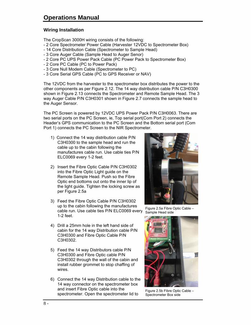
Wiring Installation The CropScan 3000H wiring consists of the following: - 2 Core Spectrometer Power Cable (Harvester 12VDC to Spectrometer Box) - 14 Core Distribution Cable (Spectrometer to Sample Head) - 3 Core Auger Cable (Sample Head to Auger Senor) - 2 Core PC UPS Power Pack Cable (PC Power Pack to Spectrometer Box) - 2 Core PC Cable (PC to Power Pack) - 3 Core Null Modem Cable (Spectrometer to PC) - 3 Core Serial GPS Cable (PC to GPS Receiver or NAV) The 12VDC from the harvester to the spectrometer box distributes the power to the other components as per Figure 2.12. The 14 way distribution cable P/N C3H0300 shown in Figure 2.13 connects the Spectrometer and Remote Sample Head. The 3 way Auger Cable P/N C3H0301 shown in Figure 2.7 connects the sample head to the Auger Sensor. The PC Screen is powered by 12VDC UPS Power Pack P/N C3H0063. There are two serial ports on the PC Screen, ie, Top serial port(Com Port 2) connects the Header’s GPS communication to the PC Screen and the Bottom serial port (Com Port 1) connects the PC Screen to the NIR Spectrometer.
1) Connect the 14 way distribution cable P/N C3H0300 to the sample head and run the cable up to the cabin following the manufactures cable run. Use cable ties P/N ELC0069 every 1-2 feet.
2) Insert the Fibre Optic Cable P/N C3H0302 into the Fibre Optic Light guide on the Remote Sample Head. Push so the Fibre Optic end bottoms out onto the inner lip of the light guide. Tighten the locking screw as per Figure 2.5a
3) Feed the Fibre Optic Cable P/N C3H0302 up to the cabin following the manufactures cable run. Use cable ties P/N ELC0069 every 1-2 feet.
4) Drill a 25mm hole in the left hand side of cabin for the 14 way Distribution cable P/N C3H0300 and Fibre Optic Cable P/N C3H0302.
5) Feed the 14 way Distributors cable P/N C3H0300 and Fibre Optic cable P/N C3H0302 through the wall of the cabin and install rubber grommet to stop chaffing of wires.
6) Connect the 14 way Distribution cable to the 14 way connector on the spectrometer box and insert Fibre Optic cable into the spectrometer. Open the spectrometer lid to
Figure 2.5a Fibre Optic Cable – Sample Head side
Figure 2.5b Fibre Optic Cable – Spectrometer Box side

CROPSCAN 3000H ON COMBINE ANALYSER
- 9 -
tighten the Fibre Optic cable P/N C3H0302 locking screw as per Figure 2.5b
Figure 2.6 Wiring Installation from the Sample Head to the cabin
7) Connect the 2 way power cable P/N C3H0303 to the spectrometer and run
the wires up to a 12 VDC terminals. Terminate the positive and negative wires with the supplied ring terminals P/N CON0209. Cable tie P/N ELC0069 wires every 1 – 2 feet.
8) Install the 3 Way Auger Cable Receptacle P/N C3H0301 to the Remote Sample Head. Run the 3 way cable up to the Auger following the manufactures run. Use cable ties P/N ELC0069 every 1-2 foot.
9) Install the Auger Sensor Mounting bracket P/N C3H0065 to the Auger
support frame using the M8 bolt P/N CON0206, 2 x washers P/NCON0208 and nut P/N CON0207 provided. (Note install bracket as close to the pivot arm).
10) Fit the Magnetic sensor to the bracket. Adjust sensor to sit 1mm from Auger
boom. Tighten attach nuts once correct gap is reached. Refer Figure 2.7 for correct gap dimension.
11) Connect the Auger Sensor and 3 Way Auger Cable to the 3 way plug.
Figure 2.7 Auger Sensor Position

Operations Manual
10 -
12) Plug the 2 Way Power Pack Power Cable
P/NC3H0305 into the PC Power Pack receptacle. Run the 2-way cable to the Spectrometer Box and plug connector into receptacle. Plug in the 0.2m PC Power Cable P/NC3H0306 from the PC to the Power Pack as shown in Figure 2.8.
13) Install the Null Modem Cable NIR Spectrometer Cable P/N C3H0304 to port 1 of the PC Screen (Lower Port), tighten the two attach screws to secure. Run the Null Modem cable in behind the interior trim and to the spectrometer box. Connect the Null Modem Cable to the spectrometer and tight the two attach screws to secure.
14) Install the DB9 GPS Cable connector P/N C3H0307 into Port 2 of the PC
screen (Top Port). Run the cable in behind the interior trim to the GPS interface plug or receiver or Nav controller. See paragraph 15A and 15B for model specific instructions.
Figure 2.9 DB9 Pin Assignment
15A) Case IH and New
Holland Combine Harvesters. Connect the CropScan GPS wiring loom to the NAV controller under the driver’s seat (Older Models) or to the NAV connector located in the access panel behind the driver’s seat. Connect the CropScan GPS cable 12 pin connector to the NAV 12 Pin connector.
Configure the Baud and NMEA settings in the NAV options in Case Screen and Analysis Software. See Chapter 3. Figure 2.10 Case IH Installation
Baud Rate: 19200 or 38400 NMEA Output: GPGGA, GPVTG and GPGLL
Figure 2.8 PC Screen Cable

CROPSCAN 3000H ON COMBINE ANALYSER
- 11 -
15B) John Deere Combine Harvesters. Connect the CropScan GPS wiring loom to the Green Star GPS Receiver wiring loom bulkhead connector in the fwd cabin roof. Remove the bolts on the front edge of the roof to gain access to the back side of the 12 pin bulkhead connector. Run the CropScan GPS wires up into the roof to the back side of the 12 pin bulkhead connector. Install the CropScan GPS Brown wire into pin 3 of the bulkhead connector. Install the CropScan GPS Blue wire into pin 10 on the bulkhead connector. Connect the CropScan GPS cable yellow wire to the closest earthing point. Note earthing points located are under the cabin head liner.
Configure the Baud and NMEA settings in the John Deere Screen. Baud Rate: 38400 NMEA Output: GPGGA
Figure 2.11 John Deere Installation

Operations Manual
12 -
Figure 2.12 CropScan 3000H Wiring Schematic

CROPSCAN 3000H ON COMBINE ANALYSER
- 13 -
Figure 2.13 CropScan 3000H 14 Way Distribution Cable Wiring Diagram
Operations Manual
14 -
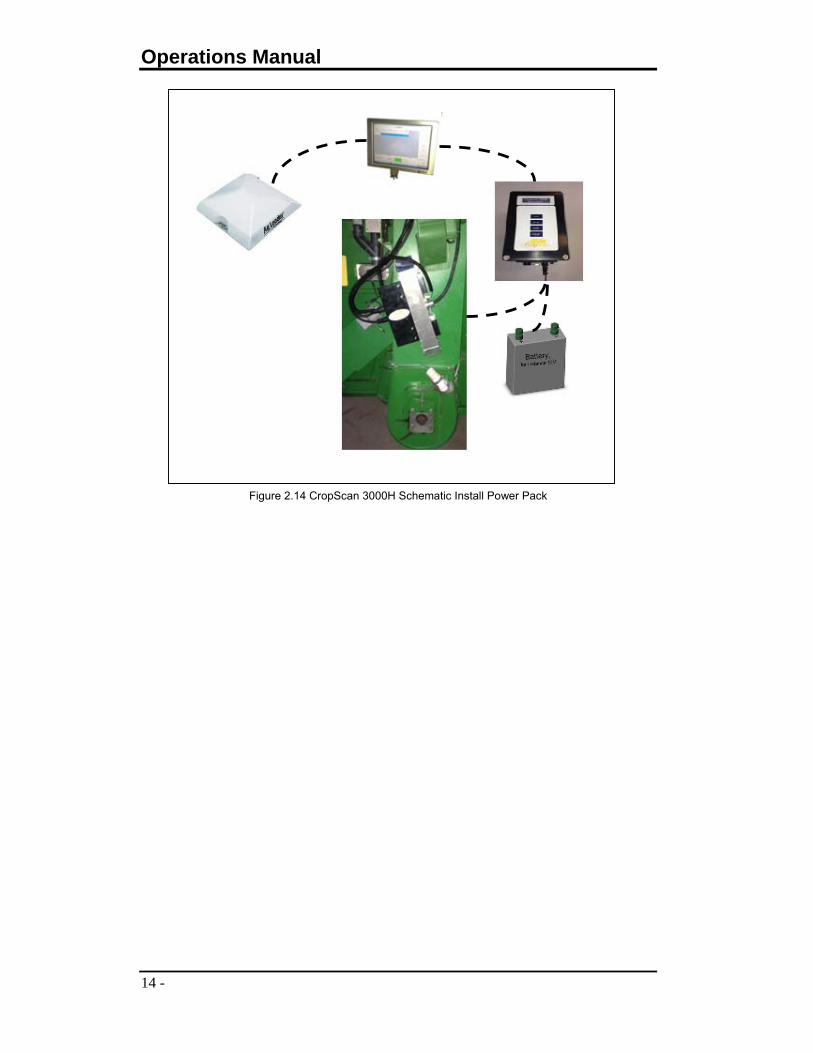
Figure 2.14 CropScan 3000H Schematic Install Power Pack

CROPSCAN 3000H ON COMBINE ANALYSER
- 15 -
Figure 2.15 Wiring to the Spectrometer Box
Figure 2.16 Wiring to PC Screen

Operations Manual
16 -
Software Options Check List – Options Tab Select Average of 5 Enter Storage Locations if you are saving the location where the grain is stored Enter Paddock Names Enter Default Bin Weight (if used) Check Harvest Start Month and make sure the Current Harvest Year is correct Check Map File format according to the Header Email Setup and CropNet Setup Check 100% – Make sure the maximum value is between 1500 and 3000 Check Noise – Make sure the values are between +0.01 and -0.01 Check Inlet Flap – Open and Close Inlet Check Outlet Flap – Open and Close Outlet Check Phototransistor:
- When the light is ON, the value should be above 50 - When the light is OFF, the value should be below -17
Reports: - Change the Report Logo by pressing around the middle blank on the top
left corner of the report screen (around 3cm from the edge) - Edit the heading by pressing on each header line
Set the times for the dimming screen, sunset and sunrise. WGA Test – Edit INI file: Check the default settings:
- 8 mm Angle = 10 - 16 mm Angle = 20 - 24 mm Angle = 30 - Angle Swing = 60 - Ref Scan Update Enabled - PT Sensor Enable (phototransistor) - Auger Sensor Enabled - New Ref Scan Time = 30 - Delay (PT OFF) = 15 - No Sample Timeout = 30 - Delay (8mm cell) = 2 - Pulse Silo Valve (ms) = 2000 - Ratio % Rejection = 10 - Lamp Off Time = 30

CROPSCAN 3000H ON COMBINE ANALYSER
- 17 -
System Operation Check List Check GPS:
- Turn combine ON so the engine is running and the GPS receiver is connected to the satellites
- Press Options and Tick the Option “Activate GPS” - Press Setup option next to the “Activate GPS” tick box - Select the correct COM port and Baud Rate for your GPS - Press Test GPS and check that the NMEA string $GPGGA is received - Press OK twice to go back to the main screen. - Press Select Product, Select AirScan - Select a Paddock Test and press OK - Press START, select the Paddock Map view and check that a data point
appears on the screen Check Auger Sensor:
- Make sure the system is running on AirScan mode - Open the Auger boom for more at least 30 seconds and then close it - Check that “Bin Ave Reset” message is received and that the number of
bins is increased Sample Check:
- If system running, Stop the system and wait for the green START button - Press Select Product - Select the product to be analysed, the Paddock Test and press OK - Press START and select Bin Ave as the screen view - Walk down to the sample head and run a sample 10 times through it - After the tenth scan, check the result on the display - Press Clear Bin - Repeat process for all the samples
Adjust Bias: - If system running, Stop the system and wait for the green START button - Press Select Product, select the product and press OK - Press the Option Tab and press the big SETUP button - Select protein or moisture by pressing on the word to highlight - Increase or decrease the bias by pressing the UP or DOWN buttons - Press SAVE to confirm new bias settings.
Operations Manual
18 -
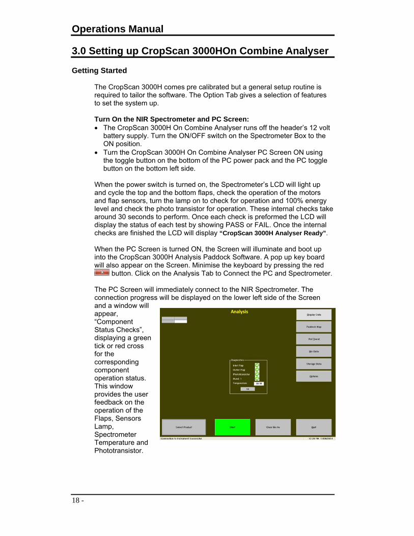
3.0 Setting up CropScan 3000HOn Combine Analyser Getting Started
The CropScan 3000H comes pre calibrated but a general setup routine is required to tailor the software. The Option Tab gives a selection of features to set the system up. Turn On the NIR Spectrometer and PC Screen: The CropScan 3000H On Combine Analyser runs off the header’s 12 volt
battery supply. Turn the ON/OFF switch on the Spectrometer Box to the ON position.
Turn the CropScan 3000H On Combine Analyser PC Screen ON using the toggle button on the bottom of the PC power pack and the PC toggle button on the bottom left side.
When the power switch is turned on, the Spectrometer’s LCD will light up and cycle the top and the bottom flaps, check the operation of the motors and flap sensors, turn the lamp on to check for operation and 100% energy level and check the photo transistor for operation. These internal checks take around 30 seconds to perform. Once each check is preformed the LCD will display the status of each test by showing PASS or FAIL. Once the internal checks are finished the LCD will display “CropScan 3000H Analyser Ready”. When the PC Screen is turned ON, the Screen will illuminate and boot up into the CropScan 3000H Analysis Paddock Software. A pop up key board will also appear on the Screen. Minimise the keyboard by pressing the red
button. Click on the Analysis Tab to Connect the PC and Spectrometer. The PC Screen will immediately connect to the NIR Spectrometer. The connection progress will be displayed on the lower left side of the Screen and a window will appear, “Component Status Checks”, displaying a green tick or red cross for the corresponding component operation status. This window provides the user feedback on the operation of the Flaps, Sensors Lamp, Spectrometer Temperature and Phototransistor.

CROPSCAN 3000H ON COMBINE ANALYSER
- 19 -
Software Set Up The CropScan 3000H Analysis Software is setup prior to shipment. The
software can also be setup to suit each farm’s operations. Press the Options Tab to setup the CropScan 3000H software settings.
The screen below shows the settings that can be changed to tailor the software to perform a number of different operations.
Trend Settings
Trend Individual: Displays each result. Trend Average of 5: Displays the results in a moving average of 5. Trend Bin Average: Converts the Trend Plot to a Bar Graph of the Bin
Averages. GPS Settings Press the Change GPS Setup
Set the Com Port to Com Port 2 (Com Port 2 is the Com on the top side of the PC)
Set the Baud Rate to match the Baud Rate of the GPS Receiver. See Header Manual for Baud Rate Settings.

Operations Manual
20 -
Other Settings
Location - Bin Weight: Tick this box if you want to record Bin by Bin Storage Data. This option allows recording of each Bin load, Storage Location and the Tonnage for each Bin using the following screen.
Out of Range Outlier: Tick this box if you want to exclude samples outside the limits set in the calibration file.
Password Protection: Tick this box to set a Password Protection to open the Options Tab. The Password is “S”
WGA Test Click on the WGA TEST Tab to open the troubleshooting tool.
Clear Results Click on Clear Results to clear the Displayed Results. Note the data file will not be erased at this time.
Connect Click on the Connect Tab to open the Connection to Instrument box. Click on the Connect or Disconnect buttons to connect or disconnect the PC to the Spectrometer.

CROPSCAN 3000H ON COMBINE ANALYSER
- 21 -
Reports Click on the Report Tab to open the Analysis Report box.
Tick the number of
Constituents to be displayed on the report.
Tick the number of different reports to be displayed or printed.
Click on the Browse Tab to report on a different file than the files loaded in the Search File Directory.
Click on the Print button to view the reports
AutoCalibration
Click the AutoCalibration Tab to make a Bias adjustment to a calibration. Enter the number of samples to use for calibration. Fill the top side of the Remote Sample Head and collect the sample through
the outlet port. The system will collect 10 sample scans for each calibration sample.
Load the next sample. Once the number of calibration samples have been analysed, return to the
PC Screen to view results. Click on the Constituent Name to view the predicted results. Enter corresponding Lab values by clicking in the lower box. Click in the other constituent Name to view 2nd constituents results. Enter corresponding Lab values by clicking in the lower box. Review the differences and Save new bias if the average error is greater
than 0.3%.

Operations Manual
22 -
Flush Press the Flush Tab to initiate a flushing sequence, the sample head will open the top and bottom flaps and allow grain to flow through the sample head to remove dust and debris. The top flap will close and a reference scan will be performed to update the 100% reference scan.
Dimming Options Dimming Times refer to the brightness of the screen. Click the Dimming Options Tab to set up the PC Screen Dimming Times. Factory default is 6.30am for Sunrise and 6.30pm for Sunset.
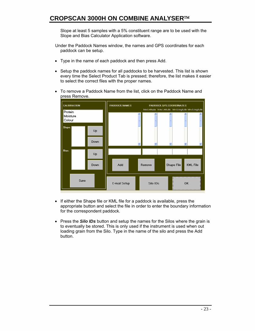
Setup Press the Setup Tab adjust Calibration Slope and Bias settings and to setup the paddock names and details.
Under the Calibration window click on the constituent to be changed. Press the Up tab to increase or Down tab to decrease the bias setting. Note:
NIR Technology Systems recommends users only adjust the Bias setting to align the CropScan 3000H to an external reference sample. To adjust the
CROPSCAN 3000H ON COMBINE ANALYSER
- 23 -
Slope at least 5 samples with a 5% constituent range are to be used with the Slope and Bias Calculator Application software.
Under the Paddock Names window, the names and GPS coordinates for each
paddock can be setup. Type in the name of each paddock and then press Add.
Setup the paddock names for all paddocks to be harvested. This list is shown
every time the Select Product Tab is pressed; therefore, the list makes it easier to select the correct files with the proper names.
To remove a Paddock Name from the list, click on the Paddock Name and
press Remove.
If either the Shape file or KML file for a paddock is available, press the appropriate button and select the file in order to enter the boundary information for the correspondent paddock.
Press the Silo IDs button and setup the names for the Silos where the grain is to eventually be stored. This is only used if the instrument is used when out loading grain from the Silo. Type in the name of the silo and press the Add button.

Operations Manual
24 -
Press the Locations button and setup the names for your grain storage locations. This list will only be shown when the Select Location option is selected.
Press the Email-Setup button to fill the settings of the email addresses that the software will use to send and receive reports when they are printed. Check with your email provider to grab this information.

CROPSCAN 3000H ON COMBINE ANALYSER
- 25 -
Operations Manual
26 -
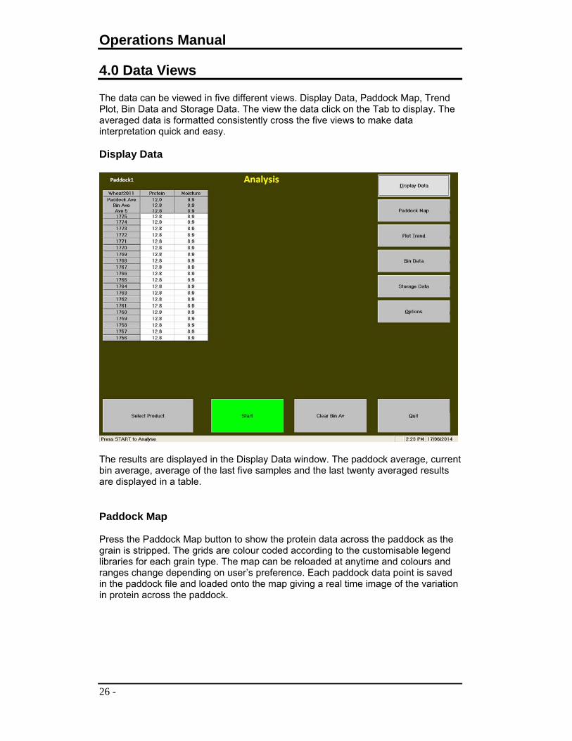
4.0 Data Views The data can be viewed in five different views. Display Data, Paddock Map, Trend Plot, Bin Data and Storage Data. The view the data click on the Tab to display. The averaged data is formatted consistently cross the five views to make data interpretation quick and easy. Display Data
The results are displayed in the Display Data window. The paddock average, current bin average, average of the last five samples and the last twenty averaged results are displayed in a table. Paddock Map Press the Paddock Map button to show the protein data across the paddock as the grain is stripped. The grids are colour coded according to the customisable legend libraries for each grain type. The map can be reloaded at anytime and colours and ranges change depending on user’s preference. Each paddock data point is saved in the paddock file and loaded onto the map giving a real time image of the variation in protein across the paddock.

CROPSCAN 3000H ON COMBINE ANALYSER
- 27 -
Trend Plot Press the Plot Trend button to display the last 20 results in a Trend Plot which show the readings for each constituent in a moving line graph. This function is good for moisture analysis as you can see if drift down and up depending on the time of day and weather conditions.

Operations Manual
28 -
Bin Data Press the Bin Data button to show averages for Protein, Moisture and Oil for each Bin load. Each time the out loading auger is extended the auger sensor is activated and the software automatically records that Bin Average and resets the Bin Average field in the software. This data is stored in a file with the same extension as the Paddock Name and is identified by the word Bin in the file extension. Eg Tommy_Bin_2014.csv. This allows users to segregate bin by bin in the paddock and save a record of the average Protein, Moisture and Oil in each bin load.
The additional option to select a storage location, tonnage and number of headers out loading each time the auger extends can be selected in the options tab. This gives users a further record of grain segregation.

CROPSCAN 3000H ON COMBINE ANALYSER
- 29 -
Storage Data Press the Storage Data button to show the records what has been stored in each bag, silo or truck. This information’s tabulates the Bin Data into Storage Locations.
Press the Options button to customise the software to suit individual farm operation. Each farmer is different and has different needs. The options tab also provides a wide range of troubleshooting tools to quickly identify problems.
The Clear Bin Av button allows the user to reset the Bin Average by pressing the button. This is used as a back up to the Auger Sensor Switch.
The quit tab exit’s the Analysis page. The system will remain connected and allow the user to navigate to Scan and Display if needed.
Operations Manual
30 -
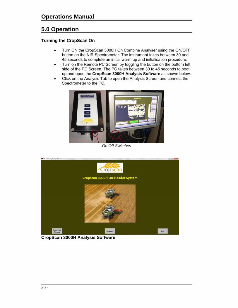
5.0 Operation Turning the CropScan On
Turn ON the CropScan 3000H On Combine Analyser using the ON/OFF button on the NIR Spectrometer. The instrument takes between 30 and 45 seconds to complete an initial warm up and initialisation procedure.
Turn on the Remote PC Screen by toggling the button on the bottom left side of the PC Screen. The PC takes between 30 to 45 seconds to boot up and open the CropScan 3000H Analysis Software as shown below.
Click on the Analysis Tab to open the Analysis Screen and connect the Spectrometer to the PC.
On Off Switches
CropScan 3000H Analysis Software
CROPSCAN 3000H ON COMBINE ANALYSER
- 31 -
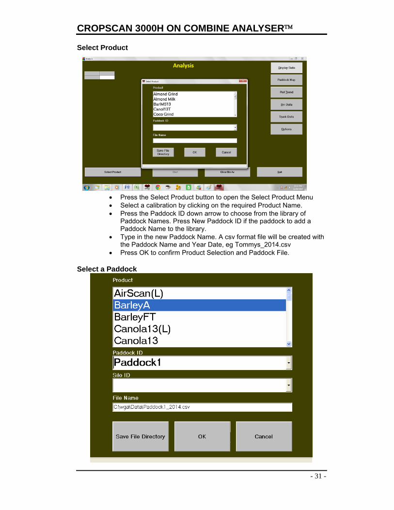
Select Product
Press the Select Product button to open the Select Product Menu Select a calibration by clicking on the required Product Name. Press the Paddock ID down arrow to choose from the library of
Paddock Names. Press New Paddock ID if the paddock to add a Paddock Name to the library.
Type in the new Paddock Name. A csv format file will be created with the Paddock Name and Year Date, eg Tommys_2014.csv
Press OK to confirm Product Selection and Paddock File. Select a Paddock
Operations Manual
32 -
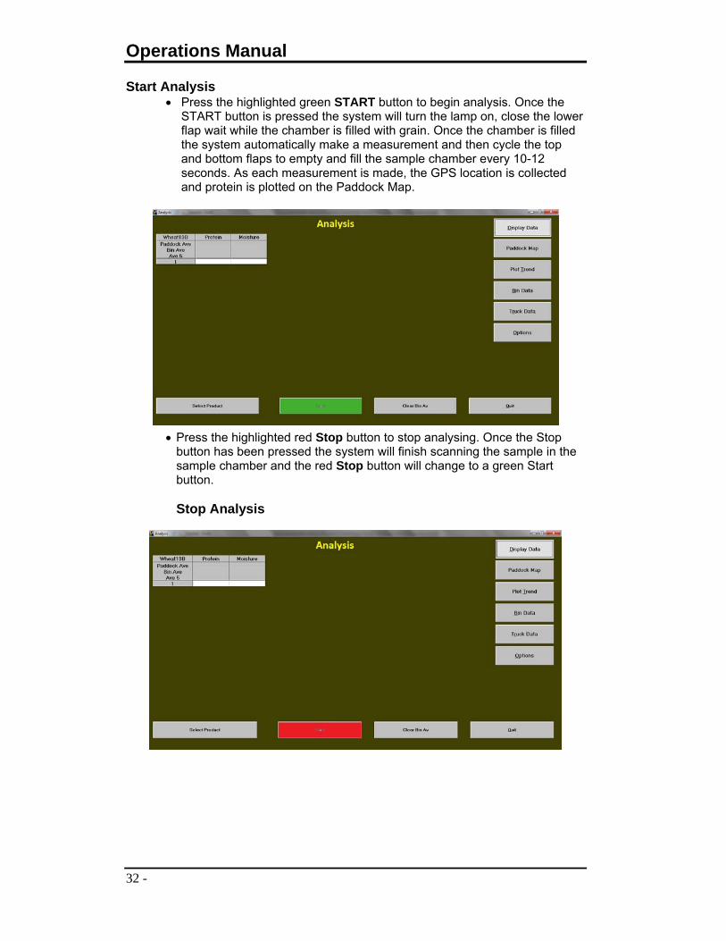
Start Analysis Press the highlighted green START button to begin analysis. Once the
START button is pressed the system will turn the lamp on, close the lower flap wait while the chamber is filled with grain. Once the chamber is filled the system automatically make a measurement and then cycle the top and bottom flaps to empty and fill the sample chamber every 10-12 seconds. As each measurement is made, the GPS location is collected and protein is plotted on the Paddock Map.
Press the highlighted red Stop button to stop analysing. Once the Stop button has been pressed the system will finish scanning the sample in the sample chamber and the red Stop button will change to a green Start button. Stop Analysis

CROPSCAN 3000H ON COMBINE ANALYSER
- 33 -
Storage Recording If the Select Location option was ticked in the Options Tab, an additional
step will be required each bin out load. A proximity sensor is activated each time the mounted auger extends, i.e. when the bin is full. At this stage, a new box appears which allows the user to select a storage location for that bin, the tonnage and the number of headers in use. When using the option Accumulative, the entered weight must be the cumulative addition of weights for all the bins harvested in the paddock and must be bigger than the previous whereas the option Tare allows the user to enter only the weight for the last bin. This gives users a further record of grain segregation.
Quick Reports
Press the Option Tab Press the Report Tab to create a quick Paddock Report Select the tick box to select the Type/s of Report you wish to create. Press the Print Button to create the Report

Operations Manual
34 -
Turning the CropScan Off Press the Quit Button Press the Shut Down Button Press OK to confirm Shut Down Switch the Spectrometer ON/OFF switch to the OFF
position

CROPSCAN 3000H ON COMBINE ANALYSER
- 35 -
6.0 Maintenance The CropScan 3000H On Combine Analyser has been designed to make maintenance as easy as possible. Before attempting any maintenance disconnect any external power supplies and ensure the instrument is turned OFF. Daily Checks
Remove Sample Cover and clean sample chamber. Remove any build up of dust and debris. Wipe the windows inside the sample chamber with a clean cloth Blow out with compressed air if available. Check Diagnostics Status at PC Screen
Changing Spectrometer Software
Before starting, make sure the spectrometer box is OFF (LCD not lit). Connect the microcontroller cable in the small 10 pin connector
located next to the RS232 connector Remove the bottom RS232 cable from the PC and connect the other
end of the microcontroller cable to thisRS232 connector in the PC Turn the spectrometer box ON Open the software RFU.exe in the PC Press on file Press on Load Flash Image Browse for the new software and press OPEN Let the software run until it finishes; it takes around 15 seconds to
download the firmware to the microcontroller. Downloading Calibration Files
Load the new calibration onto the USB Stick Insert the USB stick into the USB port in the PC Screen Press the Options Tab Press the Calibration Tab to take you to the Calibration folder Click on the Removable Drive E to Open the USB Stick Folder Copy the Calibration file by highlighting the File Click on the Organise Tab Click Copy Click on the WGA Folder Click on the Calibration Folder to open Click on the Organise Tab Click on Paste Once you can see the new Calibration File, close the window by
pressing the red cross box.
Deleting Calibration Files Press the Options Tab Press the Calibration Tab to take you to the Calibration folder Highlight the Calibration you want to delete Click on the Organise Tab Click Delete Press YES to confirm you want to delete the file

Operations Manual
36 -
Once the Calibration has been deleted close the window by pressing the red cross box.
Uploading Paddock Files, Bin Files and Storage Files
Press the Options Tab Press the Results Tab Highlight the File(s) you want to upload Click on the Organise Tab Click Copy Click on the Removable Drive E to Open the USB Stick Folder Click on the Organise Tab Click on Paste Once the Files have been copied, close the window by pressing the
red cross box.
Deleting Paddock Files, Bin Files, and Storage Files
Press the Options Tab Press the Results Tab Highlight the File(s) you want to delete Click on the Organise Tab Click Delete Press YES to confirm you want to delete the file(s) Once the Calibration has been deleted close the window by pressing
the red cross box.
Checking 100% Reference Scan
Make sure the sampling head is clean Press the Options Tab Press the WGA_Test Button Press the 100% Button and check that the lamp is turned ON Press the Scan Spectra Button Press the Sequential Button Check that the spectra is clean and the maximum value is between
1500 and 3500 units
Checking Detector Noise Make sure the sampling head is clean Press the Options Tab Press the WGA_Test Button Press the Noise Button and check that the lamp is turned OFF Press the Scan Spectra Button Press the Sequential Button Check that the spectra is between ± 0.003 units
Checking Phototransistor Make sure the sampling head is clean Press the Options Tab Press the WGA_Test Button Press the Test Phototransistor Button The square next to the button should turn GREEN

CROPSCAN 3000H ON COMBINE ANALYSER
- 37 -
Checking Flap Operation Press the Options Tab Press the WGA_Test Button Press the Inlet Open, Inlet Close, Outlet Open and Outlet Close
buttons to test the flap operation
Editing INI File Press the Options Tab Press the WGA_Test Button Press the Edit Ini File Button ONLY IF the table is empty, press the Upload Button Press on the number you want to change and use the popup
keyboard to adjust it, then press ENTER Repeat the previous step to adjust all the needed values Press the Download Button to update the values. NOTE: the
spectrograph takes around 45 seconds to reboot, let it run until the progress bar is completed
Checking Error Report
Press the Options Tab Press the Results Tab Open the file Error.log the check the errors
Checking Reference Scan File and Temperature Press the Options Tab Press the Results Tab Go to the folder “C:\Program Files\NIR Technology Analysis
Software\” and open the shortcut called VirtualStore Open the file Hund.csv to check the history of reference scans.
Changing Lamp Fitting
Make sure the lamp is OFF Remove 4 screws from the lamp probe Pull electrical cover away so you can get access to lamp fitting Unscrew the 4 M3 lamp fitting screws Pull lamp fitting away from light probe Remove lamp and discard Install new lamp using clean cloth to hold the lamp bulb. NOTE: it is
important that the new bulb remains clean and oil free
Changing External Fuse
Unscrew the fuse holder located on the spectrometer box between the ON/OFF switch and the RS232 connector
Remove and discard the fuse Put the new fuse in and screw the fuse holder back into place
Opening the 3000H Spectrometer
Use the Spectrometer Key P/N 3CH0051 to undo both plastic screws Open the box using the hinges Make sure to close the box when finished and tighten plastic screws

Operations Manual
38 -
Foreign Matter Foreign matter, such as chaff, dirt and straw, will affect the results. If the thrashed grain flowing through the Remote Sample Chamber contains excessive Foreign Matter then adjust the settings for the harvester to reduce the trash. Temperature dependence Both sample and instrument temperature are important factors to making accurate measurement of chemical components. Sample temperature should be between 10-45C, however the most accurate measurements will be made between 25 and 35C. The calibrations should be developed using samples at 10 and 45C as well as 28C, in order to train the instrument to recognise samples with high or low temperatures. Instrument temperature is also included in the calibration process. However the instrument response is corrected for temperature between 10 and 45C. It is recommended that the NIR Spectrometer be turned on 10 minutes prior to starting to strip grain. The systems internal heating system will heat the system up to 32 degrees and switch off once this temperature is reached. Once the spectrometer drops below 28 degrees the heating system will turn on until 32 degrees is reached. The system temperature is constantly monitors throughout the day recording the temp in the hund.csv file each half hour.

CROPSCAN 3000H ON COMBINE ANALYSER
- 39 -
7.0 Troubleshooting
Problem Solution CropScan 3000H On Combine Analyser does not start.
Ensure that the power is connected and that the power supply is functional.
Check the LCD Display has power.
Turn OFF then ON, to reboot the system.
Check external fuse, Replace if blown.
Power is supplied to the LCD, but CropScan 3000H On Combine Analyser does not start:
Turn the CropScan 3000H On Combine Analyser OFF, wait one minute, and try again. If after three attempts the CropScan 3000H On Combine Analyser still does not start, Contact [email protected]
Analysis Errors:
Outside Calibration Range The results of the analysis are outside the predefined limits of the calibration file. Check the chamber for blockages. Perform a Flush in the Options Tab to clean the chamber a force a new reference scan.

Operations Manual
40 -
PC will not start
Toggle the On button on the bottom side of the PC. Wait a few minutes for the PC to boot and open the 3000H Analysis Software. Check PC wiring if the PC will not Start.
Lamp Intensity Error The lamp is either obstructed, faulty or not receiving enough power. Clean the inside of the Remote Sample Head, especially the side of the holder the lamp illuminates. If the lamp does not turn on, see Maintenance to replace the lamp. If battery is low, change to an external power supply. See Maintenance.
No Product Calibrations Installed
Check the Calibration Folder for calibration. If no calibrations are installed contact [email protected]
Calibration File Invalid The calibration file selected has been corrupted and cannot be opened. Select another calibration or delete and replace the corrupted file. Contact [email protected] for further support.
Software will not open If the PC will open the 3000H Analysis Software automatically go to the C:\programfiles\nirtechnologyanalysis and click on the Paddock.exe file to open software. Contact [email protected] for further support.
No Connection The PC has not connected to the spectrometer. Press the Quit button and try the Analysis button once again. If still no connection check the serial cable between the PC and Spectrometer.
Inlet Flap Fail Open the Remote Sample Head cover and check the top flap. With no power you should be able to cycle the flap with your hand. Check for any obstruction. Check the wiring in behind the wiring cover.
Outlet Flap Fail Open the Remote Sample Head cover and check the bottom flap. With no power you should be able to cycle the flap with your hand. Check for any obstruction. Check the wiring in behind the wiring cover.
Reference Scan Fail
Open the Remote Sample Head cover and check the lamp is on. Replace lamp if the lamp is not on. Test the lamp and Ref Scan buy opening the Option tab and use the WGA TEST functions. Refer Manual.
Low Temperature Open the Spectrometer Box and feel the Stainless Steel shield. You should feel this to be warm to touch with your hand. Check wires.

CROPSCAN 3000H ON COMBINE ANALYSER
- 41 -
Hardware Error Cycle Power and reboot spectrometer. Contact [email protected] for further troubleshooting.
No Hardware Response
An internal connection has failed. If problem persists contact [email protected] for further troubleshooting.
Microcontroller Failure Indicates that the program file has been corrupted. Use the Rabbit Utility to connect to the CropScan 3000HOn Combine Analyser and download the program file from the C:\Temp\3000H.bin file stored in the PC.
Unknown Time Out Error
Inlet Sensor Failure Check Inlet Sensor, open Sample Head Cover and close flap and check red light illumination when closed.
Outlet Sensor Failure Check Inlet Sensor, open Sample Head Cover and close flap and check red light illumination when closed.
Phototransistor Failure
Using WGA TEST, turn lamp on and check phototransistor level by pressing the Sample temp button. The number should be above 30.
Reference Scan Failure Click on the Options Tab and press the FLUSH Tab to clean chamber and initiate reference scan.
Detector Saturation Detector received too much energy. Check Light Probe Spacer is correct. Check 100% using WGA TEST. The acceptable level is 1500 to 3500 units.
No Sample Detected No sample inside the sampling head chamber. Check that grain is flowing
Operations Manual
42 -
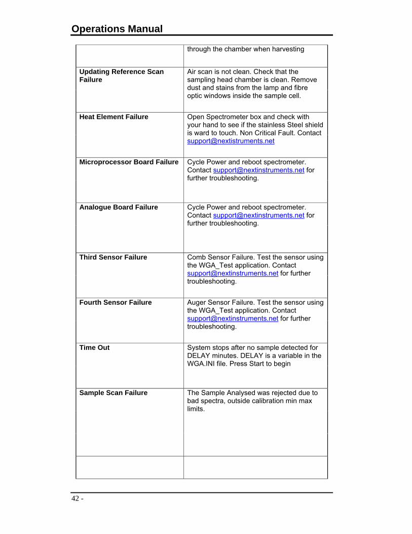
through the chamber when harvesting
Updating Reference Scan Failure
Air scan is not clean. Check that the sampling head chamber is clean. Remove dust and stains from the lamp and fibre optic windows inside the sample cell.
Heat Element Failure Open Spectrometer box and check with your hand to see if the stainless Steel shield is ward to touch. Non Critical Fault. Contact [email protected]
Microprocessor Board Failure Cycle Power and reboot spectrometer. Contact [email protected] for further troubleshooting.
Analogue Board Failure Cycle Power and reboot spectrometer. Contact [email protected] for further troubleshooting.
Third Sensor Failure Comb Sensor Failure. Test the sensor using the WGA_Test application. Contact [email protected] for further troubleshooting.
Fourth Sensor Failure Auger Sensor Failure. Test the sensor using the WGA_Test application. Contact [email protected] for further troubleshooting.
Time Out System stops after no sample detected for DELAY minutes. DELAY is a variable in the WGA.INI file. Press Start to begin
Sample Scan Failure The Sample Analysed was rejected due to bad spectra, outside calibration min max limits.

CROPSCAN 3000H ON COMBINE ANALYSER
- 43 -
Comb Not Down System can’t analyse if the comb is not down. Make sure the comb is down and check the comb sensor. Contact [email protected] for further troubleshooting.
User Stopped Process User stops operation in the middle of an analysis. Press Start to begin

Operations Manual
44 -
8.0 Warranty The CropScan 3000H On Combine Analyser is warranted for 12 months. The warranty includes all parts and labour for the repair of any component that has failed within the recommended operating conditions. If there is damage to the instrument due to inappropriate handling, then the warranty will be voided.
9.0 Disclaimer The CropScan 3000H On Combine Analyser are designed to function as Near Infrared Spectrophotometers. These instruments measure the amount of light absorbed by the sample and the computer applies a calibration model for a specific product and thereby calculates the constituent values. Calibrations supplied with these instruments are not guaranteed to perform to any standard or specification. Owners are responsible for evaluating the calibrations used within these instruments. Owners are responsible for interpreting and using the information provided by these instruments at their discretion. NIR Technology Systems takes no responsibility for any damages or costs incurred by the user based on the information provided by the instrument.

CROPSCAN 3000H ON COMBINE ANALYSER
- 45 -
10.0 Calibration of NIR Instruments Introduction NIR spectroscopy is a secondary or correlative technique i.e. the spectral data collected is correlated through statistical means to some reference (laboratory) data. Regression techniques are used in order to develop a model, which is subsequently downloaded into an NIR analyser for use as a prediction tool. The following steps, also presented in the following flow chart, outline the general steps in developing a calibration:
Optimise sampling method. Pathlength considerations (CropScan 2-4abs, NIT 0-2abs) Homogenisation procedures (FOP and NIT)
Reproducibility of chosen sampling technique
Sample collection Successful calibrations usually contain around 100 or more
samples. Should contain most of the variability expected for “real”
samples.
Constituent concentrations ideally should be evenly distributed (box car distribution).
Reference Analyses
Should be performed using accepted reference method. Should be performed in duplicate (for error estimation in final
method).
Should not differ by more than 5% (if so, repeat). Spectral Data
Samples should be run in duplicate. Store spectral data along with reference data (Excel).
Regression Analysis Use chemometrics software package to perform:
Partial Least Squares (PLS) Analysis (Multiple Wavelengths).
Multiple Linear Regression (MLR) (Discrete Wavelengths).
Download the Model Validate the model on “real” samples.
Evaluate temperature stability.
Evaluate parameters such as repeatability and reproducibility.

Operations Manual
46 -
Flow Chart of Calibration Development
Optimise Pathlength
Ensure Reproducible Spectra
Select Samples (Box Car Distribution)
Analyse Samples In Duplicate
Scan Samples In Duplicate
PLS or MLR Calibration
Evaluate Calibration Models
Add 5 Low Temp and 5 High Temp Scans
Download Calibration To Analyser
Test Temperature Stability and Repeatability

CROPSCAN 3000H ON COMBINE ANALYSER
- 47 -
Calibration Techniques Traditional Method for UV-Vis: Simple Linear Regression (SLR) sometimes known as Univariate Regression. NIR Region: Usually requires some form of baseline correction, as a result of skew (caused by scatter or poorly resolved or overlapping peaks). As such, Multiple Linear Regression (MLR) techniques were developed to correct for these anomalies. SLR follows the form of a straight line:
01% bxbY
Where: Y is the constituent of interest X is the absorbance at a specific wavelength b1 is the Calibration Factor or Slope or Coefficient b0 is the Intercept or Offset
Multiple linear Regression (MLR) Used most commonly in UV-Vis and NIR to monitor absorbance or reflection at several wavelengths (filters) and relate these individual measures to the concentration of some analyte. The model has the following general form. y=b0+b1x1+b2x2 Where: b0=y-intercept b1 and b2=partial regression coefficients Used in the case where the determination of one component is being interfered with by another. A simple two-component example serves as an example.
Sample Absorbance = 0.6Concentration = 0.035mM
0
0.2
0.4
0.6
0.8
1
0 0.01 0.02 0.03 0.04 0.05 0.06
Concentration (mM)
Ab
sorb
ance

Operations Manual
48 -
Univariate calibration using one wavelength �14 shows a high correlation to tryptophan concentration, but the predictive ability is poor.
Model [C]=-2.00+38.51A14 Actual 7 14 27 Predicted 10.26 11.14 28.20 Addition of a second wavelength to the model, based on visual inspection of the spectral data, shows that �21 is relatively free from the absorption of tryptophan and contains more information on tyrosine. Model [C]=-0.00067+43.68A14+39.78A21 A21 compensates for the absorbance due to tyrosine. Actual 7 14 27 Predicted 7.03 14.04 26.99
CROPSCAN 3000H ON COMBINE ANALYSER
- 49 -
There are two methods for performing MLR Stepwise Forward Stepwise Backward Stepwise Forward
Select the first wavelength with the highest correlation. Regression looks for next wavelength, which will increase the correlation and
reduce the error. Process is continued until the addition of the next wavelength has no effect
or starts to reduce the correlation and increase the error. Best results from derivative spectra (removes baseline effects and spectral
data are not intercorrelated). This technique, when used with derivative spectra, usually only requires two
or three terms in the calibration equation. This reduces the tendency to overfit the data and results in more reliable predictions. (Note, in order to use derivative spectra, a full scanning spectrophotometer is required).
Stepwise Backward
Takes all wavelength data until error increases and correlation drops. Used in original filter based instruments (Technicon, Dickey-John Perten).
Can easily overfit data set resulting in poor prediction and poor
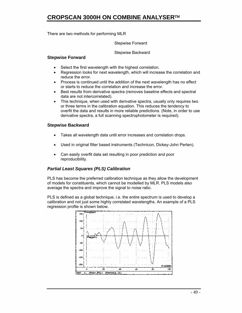
reproducibility. Partial Least Squares (PLS) Calibration PLS has become the preferred calibration technique as they allow the development of models for constituents, which cannot be modelled by MLR. PLS models also average the spectra and improve the signal to noise ratio. PLS is defined as a global technique, i.e. the entire spectrum is used to develop a calibration and not just some highly correlated wavelengths. An example of a PLS regression profile is shown below.

Operations Manual
50 -
The plot represents the weightings or loadings, which are placed on each part of the spectrum. By adding the weighted wavelength readings and adding the regression offset b0, a value of the constituent is obtained using the following equation:
383822110 ..........% bbbbY
Calibrating with Temperature Stabilisation Samples The most reliable method of correcting for temperature effects is to add a set of spectra to the calibration file that were collected under low and high temperatures. The procedure to stabilise a calibration is as follows; - Select 5 samples from the calibration set that represent a broad range of protein and moisture values. - Scan each sample at room temperature when the instrument has been left on to reach the optimum temperature range, eg 25-35C. - Place the instrument into a cold room or refrigerator for 2 hours. Remove the instrument and turn on. When the instrument reaches 10C, scan the 5 samples again and save the spectral data. - Place the instrument into a hot chamber set at 45C for 2 hours. Remove the instrument and turn on. Scan the five samples again and store the spectral data. - Place the samples into the refrigerator or cold room for 2 hours. Remove and scan the five samples in the instrument which should be at normal operating temperature. Save the spectral data. - Place the samples in a hot chamber set at 45C for 2 hours. Remove and scan as before. Upload the 25 sets of spectra and add them to the calibration file and recalibrate. By including samples with high and low temperature variations, for both the samples and instrument, then it trains the calibration to be less sensitive to temperature effects. Note that this procedure is required for every calibration set.
Validation of a NIR Method
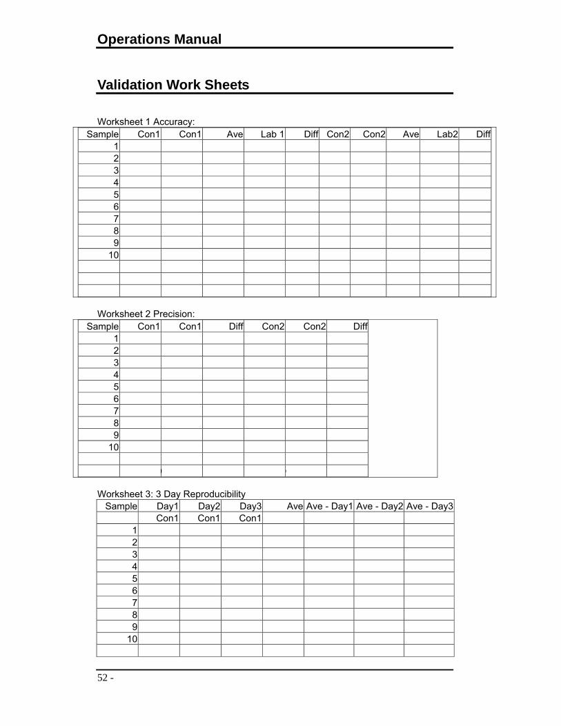
Developing a NIR calibration is not the completion of the job when developing a NIR method. The calibration needs to be validated. The following steps are intended as a guide to a Validation Procedure for a NIR Method. 1) Accuracy = Standard Deviation of Differences between the predicted (NIR results) vs the reference or lab results for 10 samples across the range of values to be analysed in the future. Using the calibration model previously developed based on a calibration set, analyse between 20 and 50 fresh samples in duplicate of the same product using the same sampling device, sample temperature and the same analytical method for
CROPSCAN 3000H ON COMBINE ANALYSER
- 51 -
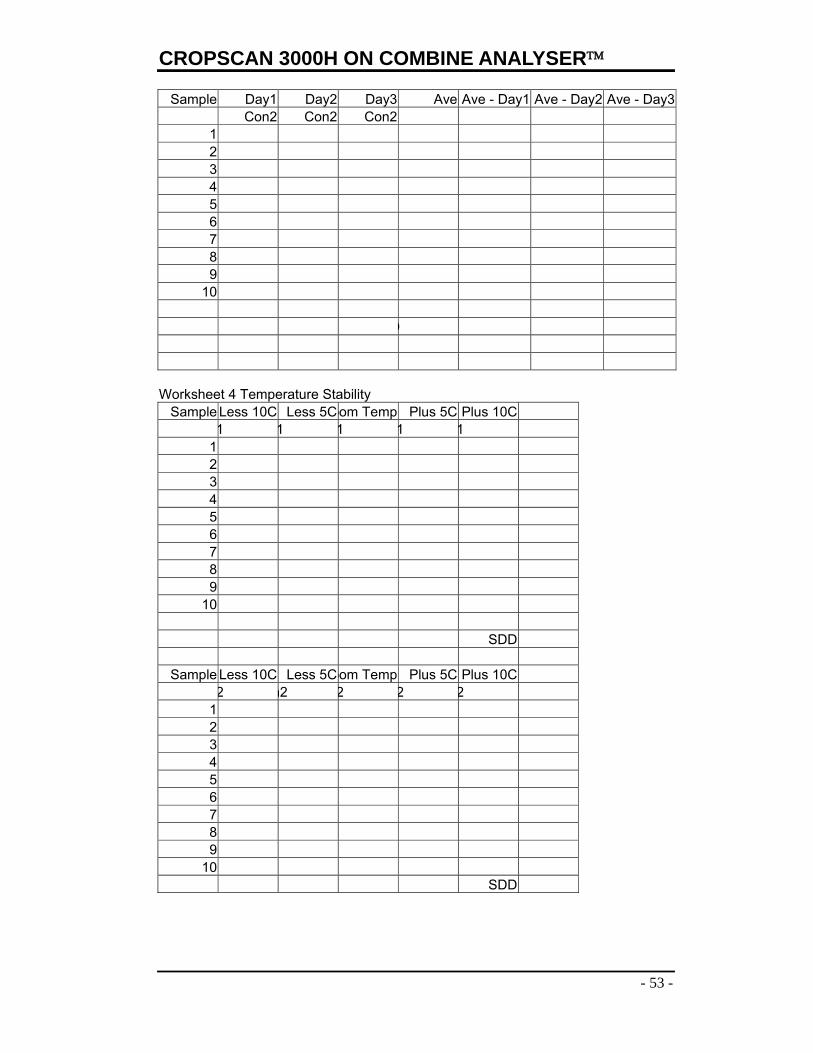
determination of the reference results. Record these results in sheet 1 of the attached Excel Worksheet, ie, Validation Document. All samples should be repacked between analyses. All lab tests should be done in duplicate using different portions of the same sample. 2) Precision = Standard Deviation of Differences between duplicate predicted results using the NIR analyser. The duplicate results in step 1, provide the data used to compute the precision of the method. Record these results into sheet 2 of the worksheet. 3) 3 Day Reproducibility = Standard Deviation of Differences between the average of the predicted results over 3 days vs each day results. Analyse 10 samples used in step 1, in duplicate, on three consecutive days. It is acceptable to use the results from step 1 as Day 1 samples. Record the results into sheet 3 of the worksheet. 4) Temperature Stability = the differences between the results obtained at standard temperature and the results obtained at +/-5 and 10C from the standard temperature. Cool three samples to –10C below the standard temperature used to develop the calibration, ie, room temperature = 22C – 10C = 12C. Analyse these samples and record the results in sheet 4. As the samples warm up to 17C analyse them again and record the results in sheet 4. Analyse the samples at the standard temperature and record the results. Warm the samples to 27C and then 32C and analyses and record the results. Validation Results: The data generated by the Validation Procedure will lead to one of two situations. 1) Errors are too high and there is a need to go back and further develop the method. By saving all the spectral data used in the validation process, the spectra and lab data can be added to the calibration set. 2) Errors are within acceptable limits and therefore the method is accepted and released. The errors are used to define the performance of the method so that future improvements to the calibration set and sampling can be compared. If the improvements reduce the errors then method is updated. If not then, there is a criterion to make decisions.
Operations Manual
52 -
Validation Work Sheets
Worksheet 1 Accuracy:
Sample Con1 Con1 Ave Lab 1 Diff Con2 Con2 Ave Lab2 Diff1 2 3 4 5 6 7 8 9
10
Worksheet 2 Precision:
Sample Con1 Con1 Diff Con2 Con2 Diff1 2 3 4 5 6 7 8 9
10
D D
Worksheet 3: 3 Day Reproducibility
Sample Day1 Day2 Day3 Ave Ave - Day1 Ave - Day2 Ave - Day3 Con1 Con1 Con1
1 2 3 4 5 6 7 8 9
10
CROPSCAN 3000H ON COMBINE ANALYSER
- 53 -
Sample Day1 Day2 Day3 Ave Ave - Day1 Ave - Day2 Ave - Day3 Con2 Con2 Con2
1 2 3 4 5 6 7 8 9
10
D
Worksheet 4 Temperature Stability
Sample Less 10C Less 5Coom Temp Plus 5C Plus 10C 1 1 1 1 1
1 2 3 4 5 6 7 8 9
10 SDD
Sample Less 10C Less 5Coom Temp Plus 5C Plus 10C 2 n2 2 2 2
1 2 3 4 5 6 7 8 9
10 SDD