Criticality Control in Operations with Fissile Material · CRITICALITY CONTROL IN OPERATIONS WITH...
73
?-7^- LA-3366 (Rev) Criticality Control in Operations with Fissile Material THIS DOCUMENT CONFIRMED AS UNCLASSIFIED DIVISION OF CLASSIFICATION BY &W{± h DATE scientific laboratory of the University of California LOS ALAMOS, NEWMEXICO 87544 F.S11 fi UNITED STATES ATOMIC ENERGY COMMISSION CONTRACT W-7403-ENG. 36
Transcript of Criticality Control in Operations with Fissile Material · CRITICALITY CONTROL IN OPERATIONS WITH...

?-7^-
LA-3366 (Rev)
Criticality Control
in Operations with Fissile Material
THIS DOCUMENT CONFIRMED ASUNCLASSIFIED
DIVISION OF CLASSIFICATIONBY &W{± hDATE
scientific laboratoryof the University of California
LOS ALAMOS, NEW MEXICO 87544
F.S11 fiUNITED STATES
ATOMIC ENERGY COMMISSIONCONTRACT W-7403-ENG. 36

This report was prepared as an account of work sponsored by the UnitedStates Government. Neither the United States nor the United States AtomicEnergy Commission, nor any of their employees, nor any of their contrac-tors, subcontractors, or their employees, makes any warranty, express or im-plied, or assumes any legal liability or responsibility for the accuracy, com-pleteness or usefulness of any information, apparatus, product or process dis-closed, or represents that its use would not infringe privately owned rights.
Printed in the United States of America. Available fromNational Technical Information Service
U. S. Department of Commerce5285 Port Royal Road
Springfield, Virginia 22151Price: Printed Copy $3.00; Microfiche $0.95

LA-3366 (Rev)UC-41 & 46
ISSUED: November 1972
I o sWa I a m o sscientific laboratory
of the University of CaliforniaLOS ALAMOS, NEW MEXICO 87544
Criticality Control
in Operations with Fissile Material
by
H. C. Paxton
This report supersedes LA-3366.
-NOTICE-Thls report was prepared as an account of worksponsored by the United States Government. Neitherthe United States nor the United States Atomic EnergyCommission, nor any of their employees, nor any oftheir contractors, subcontractors, or their employees,makes any warranty, express or Implied, or assumes anylegal liability or responsibility for the accuracy, com-pleteness or usefulness of any Information, apparatus,product or process disclosed, or represents that its usewould not infringe privately owned rights.

CONTENTS
PREFACE i v
ABSTRACT 1
I. BACKGROUND 1
The AEC 1Safety Experience 2Criticallty Risk in Perspective 7Definition of Nuclear Criticallty Safety 8Practical Nuclear-Safety Fundamentals . . . . . 8
II. FUNDAMENTALS OF CRITICALITY 9
Qualitative Criticality Concepts 9Origins of Criticality Data 10Typical Detailed Computational Techniques 11Simple Computation 14
III. CRITICALITY INFORMATION—INDIVIDUAL UNITS AT NORMAL DENSITY . . 14
Relationships for Shape Conversion 15Effects of Various Reflectors 18More About Solutions and Mixtures 19Heterogeneous Uranium-Water Systems . 21More About Poisons 23
IV. CRITICALITY INFORMATION—LOW-DENSITY UNITS AND ARRAYS 24
Homogeneous Low-Density Systems 25Near-Equilateral Air-Spaced Arrays 27Storage Applications 29Surface-Density Model of Arrays 31Groups of a Few Fissile Units 34Further Observations About Interaction . 35
V. GENERAL CRITICALITY-CONTROL PRACTICES 37
Tools for Criticality Evaluation 37The General Criticallty Safety Standard 38Specialized Standards and Criticality Safety Guides 40Transport Regulations 42Continuing Interest 43
ACKNOWLEDGMENTS 44
REFERENCES 44
APPENDIX. Selected Figures from TID-7Q28, "Critical Dimensions of
Systems Containing U 2 3 5, Pu 2 3 9, and rj233." 47
111

PREFACE
This account is intended to promote a broadened base for nuclear
safety and to help provide a feeling for criticality control to anyone
who works with fissile material. As the quantity of reactor fuel
increases, and as costs of fabrication, handling, and processing become
more significant, it is presumed that restrictive rules by a few nuclear-
safety specialises will no longer be tolerable. The alternative, which
we espouse, is to raake criticality control a live, active part of chem-
ical and nuclear engineering, instead of a superposed topic with almost
negative implications.
We assume that a feeling for nuclear safety can be developed without
a working knowledge of theoretical reactor physics but with some appre-
ciation for its capability. There are now considerable critical data,
both experimental and computed, upon which empirical know-how can be
based. This report emphasizes such data and attempts to make them
understandable in terms of simple reactor-physics concepts.
We hope that a supplement eventually may give examples of applica-
tion to a variety of real operations. Such illustrations are desirable
to clarify methods of criticality control—further, they should add
appeal for the process designer and operating engineer. There will be
no attempt, however, to turn this into a handbook. Our purpose would
be to show how the subject may be viewed and how one can go about incor-
porating nuclear safety into the design of an operation, not to provide
a stereotyped set of rules.
Response to the original Los Alamos report of this title (LA-3366)
was encouraging enough to stimulate the present revision. Among the
many whose ideas are borrowed for this account, David R. Smith and
Joseph T. Thomas have contributed especially generously. Further,
Dixon Callihan, Elizabeth B. Johnson, and Joseph T. Thomas have kindly
consented to the reproduction of numerous figures from the report TID-
7028, "Critical Dimensions of Systems Containing U 2 3 5, Pu 2 3 9, and U23;>."
For our purpose, "fissile" materials are the usual reactor fuels,235Uf 239pu, and 233\j. fha terra "fissionable" refers to a broaderclass that includes, as well as these common fuels, other isotopesthat can fission, e.g., 2 3 8U, 2*°Pu, and 232xh.
iv
CRITICALITY CONTROL IN OPERATIONS
WITH FISSILE MATERIAL
by
H. C. Paxton
ABSTRACT
This discussion of criticality control la intended to encourage aworking knowledge on the part of those who design and perform operationswith fissile material. As background, requirements of the Atomic EnergyAct are interpreted, and nuclear-safety experience is outlined. Bothare shown to be compatible with reasonable principles of nuclear safety.Next, empirical criticality information is presented to help develop afeeling for conditions to be avoided during operations. Criticallty-control methods that are consistent with the stated principles andavailable criticality data are described in the final section.
I. BACKGROUND
THE ABC
We cannot discuss nuclear safety realistically
without examining the influence of the U. S. Atomic
Energy Commission. The AEC was appointed legal
guardian of the ruclear industry by Congress through
the Atomic Energy Act. Like many a parent, it became
accustomed to nursing the infant industry, and now
has some difficulty adjusting to the problems of an
adolescent. Failure to relax early controls retards
the development of responsibility, yet the youth may
get into trouble if there Is relaxation before re-
sponsibility is demonstrated. This apparent paradox
will be resolved only when the industry recognizes
its own maturity and the AEC does also. Even then,
a dual responsibility traces back to the Act, and
satisfactory balance of this responsibility will de-
pend upon sympathetic mutual understanding.
The basis for this understanding must start
with the safety responsibility that Congress requires
of the AEC. The tone is set by typicsl quotations
from the Act.
Sec. 3. PURPOSE: "It is the purpose...to effectuate
the policies...by providing for...a program to
encourage widespread participation in the
development and utilization of atomic energy
for peaceful purposes to the maximum extent
consistent with the common defense and security
and with the health and safety of the public..."
Sec. 31. RESEARCH ASSISTANCE: "...the Commission
is authorized and directed to make arrangements
...for research and development activities re-
lating to...the protection of health and the
promotion of safety during research and produc-
tion activities."
Sec. 41. OWNERSHIP AND OPERATION OF PRODUCTION
FACILITIES: "Any contract...shall contain pro-
visions. ..obligating the contractor... to comply
with all safety and security regulations which
may be prescribed by the Commission."
Sec. 53. DOMESTIC DISTRIBUTION OF SPECIAL NUCLEAR
MATERIAL: "Each license...shall be subject to
the following conditions...special nuclear ma-
terials shall be distributed only pursuant to
such safety standards as may be established by
rule of the Commission to protect health and to
minimize danger to life or property,..."
Sec. 182, LICENSE APPLICATIONS: "... the applicant
shall state...such...information as the Commis-
sion oay, by rule or regulation, deem necessary
UNCLASSIFIED
...to find that the utilization or production of
special nuclear material...will provide adequate
protection to the health and safety of the public."
Of course, these provisions are subject to in-
terpretations ranging from stringent to reasonably
liberal. For example, the word "adequate" in the
last quotation may be ignored or emphasized. Strict
interpretation was natural during the infancy of the
nuclear industry, but liberalization should be ex-
pected as the industry matures and demonstrates its
responsibility. A reasonable attitude toward safety
regulation is expressed in commentaries on the Act
that appear in the document "Improving the AEC Regu-
latory Process," dated March 1961, which was prepared
by the staff of the Joint Committee on Atomic Energy,
under James T. Ramey, then Executive Director. The
practical attitude is illustrated by a statement
(p. 61) about safety in achieving atomic goals.
"The primary objective of the atomic energy regu-
latory process should be, of course, to protect
the health and safety of the public and employ-
ees in industrial and other uses of radiation-.
As noted earlier, absolute safety is not the ob-
jective, however, for this would require discon-
tinuance of all nuclear development. Therefore,
national goals, such as development of nuclear
weapons, long-range space exploration through use
of nuclear propelled vehicles, achievement of
economic nuclear power, increased use of radio-
isotopes, and pursuit of basic atomic research,
must be considered iu determining the reason-
ableness of safety requirements."
As recognized in this statement, no processing of
fissile material presents zero risk.
In summary, the Act requires both contractor and
licensee to comply with AEC regulations designed "to
protect health and to minimize danger to life and
property" or to "provide adequate protection to the
health and safety of the public." These regulations
are supposed to recognize "widespread participation
in the development and utilization of atomic energy
for peaceful purposes to the maximum extent consist-
ent" with the above safety aims (and with the common
defense and security). Furthermore, *he AEC is di-
rected to arrange for technical safety guidance and
safety promotion.
The resulting overall picture of safety regula-
tion is fluid, something that adjusts to technical
knowledge, instead of arbitrary requirements that
are fixed for all time. This is important, because
it permits us to view criticality control within its
technical bounds, not within the limitations of ex-
isting or proposed regulation. Furthermore, it ap-
pears that the way is left open for the mutual under-
standing that was mentioned earlier. To bring about
complete understanding, the AEC must keep abreast of
technical developments and objectives of the nuclear
industry, and licensees and contractorj must demon-
strate their competence and contribute to the im-
provement of regulations.
SAFETY EXPERIENCE
There have been six supercritical accidents in
chemical process equipment but none associated with
mechanical processing, storage, or transportation.
All occurred with aqueous solutions; four involved
highly enriched uranium, and two involved plutonium.
Two of the excursions took place in areas that were
shielded to accommodate irradiated fuel, so that
personnel were protected from direct radiation.
The results of these 6 accidents have been 2
deaths, 19 significant overexposures to radiation,
no equipment damage, and negligible loss of fissile
material. In no case was there any danger to the
general public.
Each incident was a result of process or equip-
ment difficulty or maloperation (generally a combina-
tion) . There was no contribution by faulty critical-
ity information, nor by error in its interpretation.
Before proceeding from these general remarks to
more specific features of the accidents, it may be
useful to picture the usual characteristics of a
supercritical excursion in a solution. Typically,
there is a fission spike that is terminated by heat-
ing and consequent thermal expansion of the solution
and by bubble formation. If there is no loss of ma-
terial, as by splashing, fissioning continues at a
reduced rate that may have less intense spikes than
the first as bubbles sweep out of the solution. Con-
tinued addition of solution after the initial burst
will Amplify these secondary spikes. Of course, loss
of solution, or redistribution of material may term-
inate the reaction after the initial burst.
Numbers of fissions, which are quoted in the
following accounts, may require translation into
He overlooked an instance of accidental criticalityreported by J. T. Daniels, H. Howells, and T. G.Hughes: "Criticality Incident—August 24, 1970,tfindscale Works,"ANS Trans. 14, No. 1, 35-36 (Junel973i

UNCLASSIFIED
more familiar terms. A modest burst of 3 x 10
fissions deposits 1 MW-sec, 240 kcal, or 950 BTU of
energy, most of which heats the solution.
A complete listing of criticality accidents
appears in a review by W. R. Stratton, and details
are given in the references he cites. Although we
will confine our attention to accidents in proces-
sing plants, conditions that have led to excursions
in critical facilities are also instructive. The
following accounts of plant accidents are intended
to provide not only an idea of the consequences but a
general introduction to nuclear-safety practices.
The Y-12 Plant, Oak Ridge, Tennessee—June 16, 19S8.
This accident occurred in an area for the recovery
of II(93) from scrap, while a material inventory was
in progress. An empty solution-storage cylinder
(geometrically safe—see Sec. Ill) was being cleaned,
and wash water that flowed into a 55-gal drum led to
the excursion. Solution had leaked into the cylin-
der (during the time between emptying and washing)
through a valve that was supposed to provide isola-
tion from other process equipment still in operation.
Concentrated solution that first flowed into the
large-diameter drum was too shallow for criticality
until diluted by some of the wash water that followed.
Initial criticality occurred with about 2.1 kg of
II in 56 liters of solution. Further dilution
ultimately reduced the uranium concentration enough
to make the system subcritical, but not until a suc-
cession of bursts had produced a total of 1.3 x 10
fissions in 3 min. Because of the relatively low
flow rate, it is estimated that only 10 fissions
occurred in the first and largest burst. This is
consistent with the observation that the reaction
was not violent enough to splash solution out of the
drum. An initial "blue flash" was reported.
One man who was about 6 ft from the drum re-
ceived an exposure of 461 rem; other exposures were
428 rem at 18 ft, 413 rem at 16 ft, 341 rem at 15 ft,
298 rem at 22 ft, 86 rem at 31 ft, 86 rem at 37 ft,
and 29 ram at 50 ft. Exposures and distances from
the drum do not correlate closely primarily because
some routes taken out of the plant were more favor-
able than others. The exposures resulted from little
more than the initial burst (from which there is no
235U$ 235
U(93), for example, means uranium whose U enrich-ment is 93 wtX.
escape), because radiation alarms signaled the acci-
dent, and the area was evacuated promptly. The im-
portance of rapid departure can be appreciated by
comparing actual exposures with the 400-to 500-rem
range within which the chance of survival is esti-
mated to be about 50%.
The following measures were subsequently adopted
to prevent similar accidents: Equipment is isolated
by actually disconnecting transfer lines that may
contain fissile material. Only containers that
would be safe for U(93) solutions are permitted in
process areas (e.g., waste baskets are perforated,
and mop buckets have been replaced by geometrically
safe containers).
The Los Alamos Scientific Laboratory—December 30,
1958. This accident involved equipment for treating
dilute raffinate from a plutonium recovery plant.
Residual plutonium (supposedly - 0.1 g/liter) and
small quantities of americium were recovered from
the raffinate by solvent extraction in large tanks.
Again, a material inventory was in progress, and tne
tanks (all closed) were to be emptied and cleaned,
one by one. Presumably to simplify this process,
residual materials and nitric-acid wash solutions
from four vessels were emptied into one, a vertical
225-gal, 38-in.-diam tank. This collection was made
possible by the existence of many interconnecting
transfer lines. The excursion occurred in this tank
when its stirrer was turned on. Investigation showed
that there was 3.27 kg of plutonium in an 8-in.-thick
organic layer (160 liters) that floated on a dilute
aqueous solution (60 g of plutonium in 330 liters).
The initial action of the stirrer was to thicken the
center of the organic layer enough to make it super-
critical. Continued stirring immediately established
a vortex, then mixed the organic and aqueous phases,
diluting the plutonium enough so that criticality did
not recur. The excursion consisted essentially of a
single spike of 1.5 x 10 1 7 fissions. The operator,
who was standing against the tank while looking Into
a sight glass, received an exposure of 12,000 rem
(+ 50%) and died 36 h later. Two men who went to
help the victim received exposures of 134 rem and 53
rem. There was no damage to equipment and no contam-
ination, although the shock displaced the canfc sup-
port 3/8 in. and knocked the operator off a small
ladder. A radiation alarm 175 ft away was activated,
UNCLASSIFIED
UNCLASSIFIED
and a flash of light accompanying the excursion was
seen from an adjoining room.
The only explanation found for the presence of
3.3 kg of plutonium in this process which had an ex-
pected inventory of 0.125 kg is a gradual accumula-
tion of solids during the 7^-yr history of operation.
The entire recovery plant had been scheduled to be
rebuilt after another 6 months of operation. Instead
the old equipment was retired immediately.
Apart from conversion to safer equipment, the
following practices were adopted as a result of the
accident. Written procedures for all operations and
for emergencies were improved, and emphasis on nu-
clear-safety training was increased. Gamma-sensing
radiation alarms were designed and installed to pro-
vide complete coverage of process areas. Solution-
transfer lines not required for a specific operation
were blocked to minimize the opportunity for abnor-
mal interchanges. Neutron "poison" in the form of
cadmium-nitrate solution was placed in vent tanks
and vacuum-buffer tanks to protect against ajciden-
tal introduction of plutonium. (Borosilicate glass
rasclilg rings have been used for this purpose In
some plants.) Furthermore, periodic surveys with
portable neutron detectors are conducted to detect
abnormal deposits of plu .or.ium.
The Idaho Chemical Processing Plant, National Reactor
Testing Station— October 16, 1959. The primary
function of tne Idaho Chemical Processing Plant is
to purify and concentrate the fissile material in
spent reactor fuel. Thick concrete shielding pro-
tects personnel from exposure to the highly radio-
active fuel. The excursion occurred as the result
of air sparging of a bank cf safe storage cylindersHOC
that contained U(93) solution (170 g U/liter).
The sparging initiated a siphoning action that trans-
ferred about 200 liters of solution (34 kg U) from
the storage cylinders Into a 5000-gal tank containing
about 600 liters of water. Criticality in this tank19
led to a total of 4 x 10 fissions during perhaps
20 min. It is guessed that a power spike of about
10 fissions was followed by smaller spikes, and
then by more-or-less stable boiling of the solution.
The reaction terminated after an estimated 400 literst
of water was distilled into another tank.
Although there was no direct neutron and gamma
exposure, gaseous and air-borne activity spread into
operating areas through vent lines and drain
connections and triggered radiation alarms. Signifi-
cant beta-radiation dosages, 50 and 32 R, were re-
ceived by only two persons during plant evacuation.
Again, no equipment was damaged.
The desirability of a valve in the line through
which solution was transferred to the 5000-gal tank
had been foreseen, and action to correct this defi-
ciency had begun. The incident uncovered the need
for improved evacuation procedures and demonstrated
the usefulness of radiation alarms In areas that
might be effected by a nuclear incident occurring
elsewhere. Equipment and operating procedures were
reviewed to establish several lines of defense
against inadvertent transfers of fissile material.
The Idaho Chemical Processing Plant, National Reactoi'
Testing Station —January 25, 1961. This incident
differs from the others in that there is considerable
justification for viewing it as only a minor devia-
tion from normal operations. Heavy concrete shield-
ing protected personnel from direct radiation, the
ventilation system prevented airborne activity from
entering work areas, and equipment design was such
that there was no practical possibility of a destruc-
tive or persistent excursion. We discuss the inci-
dent to illustrate a situation that constituted no
hazard, but which could have had serious consequences
had there been no shielding.
The excursion occurred when about 40 liters of
uranyl-nitrate solution (200 g U(93)/Uter) was
forced upward from a 5-In.-diam section of an evap-
orator into a 24-in.-diam vapor-disengagement cylin-
der that was above the normal solution level. Pre-
sumably air had been introduced into associated
lines during attempts to clear a plugged line and to
improve the operation of two pumps. When the bubble
of air reached the evaporator, solution was expelled
from the lower section. The excursion, probably a
single spike, had a magnitude of 6 x 10 fissions.
Although radiation was sufficient to trigger alarms
end cause evacuation of the plant, no personnel ex-
posure was greater than 100 mr.
Because the possibility of an excursion in the
vapor-disengagement cylinder had been foreseen, lines
at its base led to two geometrically favorable ves-
sels with provisions for overflow to the floor. This
arrangement, as well as other features, prevented
both a large pressure buildup and a sustained reac-
tion. Largely to avoid the embarrassment of a
UNCLASSIFIED

UNCLASSIFIED
recurring incident, a grid of stainless steel con-
taining 1% boron has been installed in the 24-in.-
diam cylinder to "poison" any solution that might
enter. There are also added precautions against the
introduction of air into any solution lines where
its effect could be undesirable.
The Recuplex Plant, Hanford, Washington—April 7,
1962. The multipurpose Recuplex facility, for plu-
tonium-recovery operation, started as a pilot plant
in 1955, but with successive changes became a produc-
tion facility. The various portions of this versa-
tile plant were contained in room-size plastic hoods
(gloveboxes) to prevent external contamination. A
thorough cleanup, necessitated by deterioration of
equipment and resulting leakage, was near completion
at the time of the accident. Even visibility through
the plastic walls of the hoods had become poor.
The 69-liter glass tank in which the excursion
occurred was normally used for transfer of a dilute
side stream from solve, it-extraction columns. This
solution, which carried a fraction of a gram per
liter of plutonium residues, was then directed to a
secondary recovery process (similar to the raffinate-
treatment process of the Los Alamos accident). About
46 liters of solution containing 1400 to 1500 g of
plutonium found its way into the transfer tank and
led to the excursion. Apparently, most of the ma-
terial was aqueous solution sucked up from a sump
(into which it had overflowed from a geometrically
favorable vessel) through a temporary line that had
been used for cleanup. The total yield of 8.2 x 1CT
fissions was distributed over 37 h with about 207.
appearing in the first 1/2 h. Reconstruction of
events indicated that an initial spike of about 10
fissions was followed by smaller spikes throughout
a period of 20 min, after which boiling occurred.
The excursion was finally stopped by the boiling off
of about 6 liters of water and the settling of some
organic matter after it had extracted plutonium from
the aqueous phase.
The initial burst (accompanied by a blue flash)
triggered radiation alarms, and the plant was evacu-
ated promptly. One man who was 5 or 6 ft from the
transfer tank received a radiation dose of 110 rem,
another perhaps 9 ft away received 43 rem, and a
third at 26 ft received 19 rem. A unique feature
of the postevacuation analysis of events was the use
of a small, remotely controlled robot equipped with
television. This device, normally used for handling
irradiated fuel, was used to fix the location of the
incident, place meters and read them, and operate
valves.
There were already plans to replace Recuplex,
and the old plant was not reactivated after the
accident. Ihe modern plant makes fuller use o£ geo-
metrically favorable equipment and vessels containing
neutron poisons, it is adaptable to a variety of uses
without improvisation, and its new equipment is eas-
ier to keep clean. It is recognized that the re-
quired flexibility of a salvage plant calls for
special effort to maintain up-to-date written proce-
dures that represent realistic practice.
The United Nuclear Corporation, Wood River Junction,
R.I.—July 24, 1964. The scrap-plant facilities of
the United Nuclear Corporation were designed to re-
cover enriched uranium t"rom scrap associated with
the fabrication of reactor fuel. Initially, pickle
liquor from fuel cleaning was being processed. Oper-
ations, which had started in March, were still pre-
liminary when the accident occurred. The solution
treatment, which involved geometrically safe primary
equipment, consisted of normal solvent-extraction
operations, tiichloroethane wash of the resulting
aqueous solution, solvent recovery with sodium-
carbonate solution, concentration of the uranium so-
lution by means of an evaporator, and precipitation
as ammonium diuranate.
Because of startup uiificulties, there was an
unusual accumulation of contaminated trichloroethane,
from which uranium was recovered by tedious hand
agitation with sodium-carbonate solution. This led
to improvisation of an easier process, in which the
trichloroethane was treated in a tank intended only
for makeup of the sodium-carbonate solution used in
the normal recovery process. This tank, of nonsafe
geometry, was the site of the excursion. Neither
ths plant superintendent nor one shift supervisor
(of three) was aware of this practice. Meanwhile,235
solutions of unusually high U concentration re-
sulting from cleanout of a plugged portion of the
evaporator had been stored in the same kind of 5-in.-
diatn bottles that contained the contaminated tri-
chloroethane. Apparently, a bottle of the concen-
trated solution was mistaken for trichloroethane and
poured into the 18-in.-diam sodium-carbonate makeup
tank.
UNCLASSIFIED

UNCLASSIFIED
According to the most plausible reconstruction
of events, two excursions occurred about 2 h apart.
The first, a single spike of - 1 x 10 fissions,
took place when most of the concentrated solution
had been poured into the tank. The shock splashed
about one-fifth of the solution cut of the tank and
knocked the operator onto the floor. A flash of
light was observed. The victim, who ran out of the
building, had received an exposure estimated to be
10,000 rad, and died 49 h later.
It appears that enough solution was lost (final
content 41 to 42 liters with 2 kg of uranium mostly
as precipitate) so that the vorcex from a stirrer in
the tank was sufficient to maintain a subcritical
state. Two h after the first excursion, however,
two men re-entered the area and turned the stirrer
off and then on again some minutes later, after
which they drained the tank. (The radiation alarm
was still sounding as a result of the original
burst.) Apparently the second excursion occurred
shortly after the stirrer was turned off. It could
have been either a single burst or a sequence of
bursts; the total yield of the two excursions was
1.3 x 10 fissions. The two who drained the tank
received radiation doses of 60 to 100 rad, and expo-
sures of others who had been in the plant were minor.
(They were 40 ft or more from the first excursion.)
After the accident, the United Nuclear Corpora-
tion took action to analyze methods of operation,
including penetrating reviews of operating proce-
dures, criticality limits and controls, uranium ac-
countability and material balance, health-physics
procedures and controls, training, and emergency
procedures. Geometrically safe equipment for recov-
ering uranium from trichloroethane was put into
operation. (An alternative could have involved cir-
culation through a vessel packed with raschig rings.)
Observations. In one sense, the accident experience
in the nuclear industry has been too good. Six ac-
cidental excursions in 20 yr of processing fissile
material are obviously insufficient to give a com-
prehensive picture of the ways in which criticality
can occur and of the range of consequences. So we
must be cautious about generalizing observations,
including our introductory listing of common fea-
tures of the accidents.
It is not surprising that all incidents have
occurred in recovery plants, for the variety of
materials to be processed there requires flexibility
that is not: inherent in regular production opera-
tions. Furthermore, some of the plants involved
were built in the early days when there had tc be
more reliance on the control of batch size than is
typical of modern facilities. It is somewhat sur-
prising, however, that all the excursions involved
simple solutions instead of scrap dissolvers, because
sampling difficulties made the old batch control of
charges for dissolvers particularly unreliable. Al-
though the absence of a dissolver accident in the
older plants is partially attributable to large "ig-
norance factors" combined with normal "safety fac-
tors," there also seems to have been a measure of
good luck. Now, improved criticality information
makes it possible both to reduce the "ignorance fac-
tors" and to decrease the former dependence upon
batch-size control. We will emphasize methods of
improving safety under these conditions in later
sections.
The observed range of excursion characteristics,
lack of damage, and absence of public hazard are con-
sidered typical of solution accidents, although dis-
ruptive pressures and consequent public exposure are
possible in unusual circumstances. Certain types of
accidents with solid fissile material, particularly235 1 3
with U metal, are more likely to be violent. '
Fortunately, it is not difficult to foresee the con-
ditions, such as the falling together of large pieces
of metal, that might lead to an extreme accident.
Control of these conditions is usually straightfor-
ward and is emphasized in plant operations. Proper-
ties of solution excursions are illustrated further
by an extensive series of kinetic experiments con-
ducted at the Dijon Laboratory of the French Commi-
sariat a l'Energie Atomique.
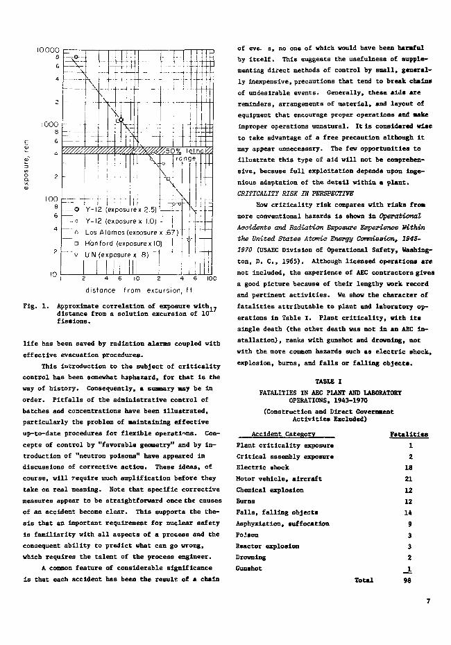
As suggested by our review, only the radiation
from an excursion is a sufficiently reliable charac-
teristic for identification. Advance warning cannot
be expected unless conditions are most unusual. Thus,
in the absence of shielding, exposure is determined
by the number of fissions and the distance from the
excursion. This is shown by the crude correlation
of Fig. 1, which is derived from observed exposures
adjusted to a yield of 10 fissions. In most in-
stances of multiple bursts, evacuation eliminated or
reduced exposure from all but the initial burst. The
one positive conclusion of our review is that human
UNCLASSIFIED
100
10
2 — -
O Y-12 (exposurex 2.5)
o Y-12 (exposure x 1.0) -
A Los Alamos (exposure x .67)
D Han ford (exposurex 10) |
v U N (exposure x .8)
2 4 6 10 2 4 6
distance from excursion, ft
100
Fig. 1. Approximate correlation of exposure withj.distance from a solution excursion of 10fissions.
life has been saved by radiation alarms coupled with
effective evacuation procedures.
This introduction to the subject of criticality
control has been somewhat haphazard, for that is the
way of history. Consequently, a summary may be in
order. Pitfalls of the administrative control of
batches and concentrations have been illustrated,
particularly the problem of maintaining effective
up-to-date procedures for flexible operations. Con-
cepts of control by "favorable geometry" and by in-
troduction of "neutron poisons" have appeared in
discussions of corrective action. These ideas, of
course, will require much amplification before they
take on real meaning. Note that specific corrective
measures appear to be straightforward once the causes
of an accident become clear. This supports the the-
sis that an important requirement for nuclear safety
is familiarity with all aspects of a process and the
consequent ability to predict what can go wrong,
which requires the talent of the process engineer.
A common feature of considerable significance
is that each accident has been the result of a chain
of eve. s, no one of which would have been harmful
by itself. This suggests the usefulness of supple-
menting direct methods of control by small, general-
ly Inexpensive, precautions that tend to break chains
of undesirable events. Generally, these aids are
reminders, arrangements of material, and layout of
equipment that encourage proper operations and Hake
improper operations unnatural. It is considered wise
to take advantage of a free precaution although It
may appear unnecessary. The few opportunities to
illustrate this type of aid will not be comprehen-
sive, because full exploitation depends upon inge-
nious adaptation of the detail within a plant.
CRITICALITY RISK IN PERSPECTIVE
How criticality risk compares with risks from
more conventional hazards is shown In Operational
Accidents and Radiation Exposure Experience Within
the United States Atomic Energy Cormtiasion, 1943-
1970 (USAEC Division of Operational Safety, Washing-
ton, D. C , 1965). Although licensed operations are
not included, the experience of AEC contractors gives
a good picture because of their lengthy work record
and pertinent activities. We show the character of
fatalities attributable to plant and laboratory op-
erations in Table I. Plant criticality, with Its
single death (the other death was not in an AEC In-
stallation) , ranks with gunshot and drowning, not
with the more common hazards such as electric shock,
explosion, burns, and falls or falling objects.
TABLE I
FATALITIES IN AEC PLANT AND LABORATORYOPERATIONS, 1943-1970
(Construction and Direct GovernmentActivities Excluded)
Accident Category
Plant criticality exposure
Critical assembly exposure
Electric shock
Motor vehicle, aircraft
Chemical explosion
Burns
Falls, falling objects
Asphyxiation, suffocation
Po.'son
Reactor explosion
Drowning
Gunshot
Fatalities
1
2
18
21
12
12
14
9
3
3
21
Total 98
Note that inclusion of AEC construction and diract
government activities would increase the total num-
ber of fatalities from 98 to 295. In terms of the
other common safety indexes, radiation accidents of
all kinds accounted for 0A% of injuries and 2% of
time lost.
Although this favorable record speaks well for
the methods of criticality control, we do not wish
to suggest that it is reason for relaxation. To
maintain a good record, improved control techniques,
especially those designed into processes, must, pre-
sumably, keep up with the foreseeable greatly in-
creased demands for fissile material. In the past,
improvements have equaled production increases, and
there is reason to believe that this neck-and-neck
process can continue.
DEFINITION OF NUCLEAR CRITICALITY SAFETY
Nuclear criticality safety is usually defined
as the art of avoiding a nuclear excursion, and, in-
deed, this is the usually practical viewpoint. How-
ever, we should recognize the situation demonstrated
by the Idaho incident of January 1961, in which the
consequences of an excursion were trivial. A proc-
ess may be designed to include shielding, confine-
ment, and other conditions like those at Idaho so
that the probability of an excursion may be allowed
to increase. In at least two instances, this alter-
native has proved less expensive than an unshielded
process with the appropriate added restrictions.
Perhaps, then, nuclear criticality safety may
be defined more precisely as protection against the
consequenc s of a nuclear excursion. Although this
extended definition points out a flaw in our use of
"criticality control" as a synonym for "nuclear crit-
icality safety," we shall continue to treat these
terms, and simply "nuclear safety," as equivalent.
PRACTICAL NUCLEAR-SAFETY FUNDAMENTALS
One purpose of this section is to lay the
groundwork for a practical "philosophy" developed
throughout the rest of the report. As explained fur-
ther in Sec. V, this philosophy is not specific to
criticality safety, but is based upon safety princi-
ples that were developed and tested before fissile
material appeared on the scene. Points of view that
we have attempted to introduce for this retson may
be stated more specifically as follows.
1. Safety is an acceptable balance of risk
against benefit; it is meaningless as a concept
isolated from other goals. It follows that safety
should be considered one of the goals of design and
operation instead of something superposed.
Although experience has shown that criticality
hazards are no more serious than other industrial
hazards, controls for balancing criticality risk
against benefit are somewhat more stringent than
is usual in nonnuclear industry. It is reasonable
that there be some allowance for the uneasiness
naturally associated with this new type of hazard.
But the extreme concept of risk elimination (as
implied by any claim that certain controls "assure"
safety or "ensure" safety) is dangerously mislead-
ing. Dismissing risk as nonexistent can detract
from the continuing job of maintaining an accept-
ably low risk level.
2. Accident prevention depends upon responsi-
bility for safety implementation (and commensurate
authority) at the supervisory level closest to oper-
ation, under the general direction and policies set
by higher management. Attempts to control detail at
a remote level are misguided.
Because of the requirement for governmental regu-
lation, great care is required to preserve this
precept in criticality safety. Remotely adminis-
tered detail discourages the on-the-job alertness
required for effective control, because it encour-
ages the attitude, "Someone else is taking care oi
us."
3. Safety regulation should be based upon pro-
fessionally generated standards and should preserve
alternative routes to safety objectives. The arbi-
trary selection of a single route (as by rule) may
eliminate the best economic balance or the most con-
venient scheme.
Inflexible rules hamstring the designer in his
traditional search for the most satisfactory way
to fulfil), his many objectives. The result is to
set safety apart from other objectives, and in-
crease the chance of an awkward operation that in-
vites Improvisation. Flexibility frees the de-
signer to apply to integrated process design the
considerable experience that has accumulated in
nuclear industry.
4. Other things being equal, simple, conven-
ient safety provisions are more effective than com-
plex or awkward arrangements. Similarly, "free" (no
cost) contributions to safety should be nurtured.
8
As an example of this principle, critinality
safety is enhanced by arrangements of material
and equipment that tend to make proper opera-
tions convenient and maloperation inconvenient.
These principles of nuclear safety will be in-
terpreted further in Sec. V, where the intent is to
suggest reasonable ways to compare conditions that
may normally be encountered in an operation to cor-
responding critical conditions. To prepare for this,
however, we shall consider in Sees. II-IV the scope
of existing information about critical configurations.
II. FUNDAMENTALS OF CRIT1CALITY
QUALITATIVE CRITICALITY CONCEPTS
By the statement that a configuration of fis-
sile material is just critical, we mean that the
average power from fission is constant. In this
condition, one of the several neutrons from the typ-
ical fission process produces a new fission. The
remaining neutrons are either lost by capture (non-
fission absorption) or by escape frcji the system
(leakage). Thus, the constant fission chain reac-
tion is linked by neutrons that are held in delicate
balance by just the right competition between fis-
sion and capture plus leakage. The features of fis-
sile systems which can influence criticality are
most easily pictured in terms of these competing
fates of neutrons.
To develop this picture of effects on critical-
ity, we must recognize one more aspect of neutron
behavior. The most likely occurrence when a typi-
cally high-energy neutron from fission strikes any
nucleus is that the neutron will simply be deflected.
(As we shall see, this is not the most probable
process when a low-energy neutron strikes a fissile
nucleus.) If the nucleus is heavy, the neutron los-
es little energy because of such a collision, but
the lightest nucleus, hydrogen (about the same mass
as the neutron), may cause great neutron-energy
loss. The process of energy loss during successive
collisions of a neutron with light nuclei, as in
passing through water, is called "neutron modera-
tion." The Importance of moderation is that the
chance of producing fission during a collision with
a fissile nucleus increases greatly as the neutron
energy becomes small.
Strictly speaking, this is the "delayed critical"state.
Now we are ready to use the simple concepts of
neutron behavior to develop intuition about criti-
cality. Let us illustrate the various influences on
criticality by limiting our attention to two common
materials, enriched uranium and water. To start, we
consider a critical sphere of U(93) metal at normal
density. The diameter of this sphere is about 6.9
in., corresponding to a volume of 2.8 liters and a
total mass of about 52 kg. If the same quantity of
material is formed into a slab or an elongated cyl-
inder, distances through which neutrons must scatter
to reach a surface are decreased (the surface-to-
volume ratio increases), so the chance that a neu-
tron may escape from the material is increased. In
other words, leakage is increased at the expense of
fission and capture, so that the new shapes are sub-
critical. Returning to the sphere, if the size is
maintained but the density of U(93) is decreased,
neutrons pass through less matter on their way to
the surface, the chance of leakage is increased, and
the new sphere is subcritical. Likewise, a decrease235
in U enrichment at constant size and density de-
creases the chance of fission relative to leakage
and capture, so that the sphere is again subcritical.
Now, several different influence? of water on
our U(93) sphere will become apparent. If the sphere
is immersed in water, some neutrons that would other-
wise escape from the surface are scattered back into
the fissile material, leakage is reduced, and the
sphere is supercritical. Actually, the critical di-
ameter of the uranium sphere drops to 5.3 in. (cor-
responding to 1.3 liters or - 24.5 kg of uranium).
Of course, this neutron-return effect is by no means
limited to water. Any material that surrounds the
fissile sphere will act similarly as a neutron "re-
flector." Objects at a distance from the sphere
will have reduced neutron-reflection effects, but
even if these objects are fissile, they may be viewed
as reflectors.
If, instead of surrounding the sphere, water is
mixed homogeneously with the U(93), there are strik-
ing changes in neutron economy as the proportion of
water increases. When the volume i I water is not
much greater than that of the uranium in the mixture,
the water's moderating effect is not enough to offset
the effect of reducing the uranium density. (Colli-
sions with hydrogen are too few for significant re-
duction of neutron energy.) Consequently, the
UNCLASSIFIED
quantity of uranium that was critical without dilu-
tion is now subcritical. With further water dilu-
tion, however, the effect of moderation takes over
(there are more and more collisions of neutrons with
hydrogen), and the system becomes increasingly super-
critical. This trend continues until the volume of
water is about 350 times that of uranium, beyond
which neutron capture by hydrogen offsets any addi-
tional effect of moderation. (Although the chance
of neutron capture during one collision with hydro-
gen is small, each neutron undergoes many collisions
at this dilution.) Here the critical diameter of a
bare sphere is roughly 15 in. and the volume is up
to 30 liters, but the U mass is only 1.4 kg. A
complete water reflector around the sphere reduces
these values to about 12-in. diam, 16 liters, and
0.8 kg of U. These last conditions are of spe-
cial significance in that they represent the minimum
critical mass of U encountered in usual processes.
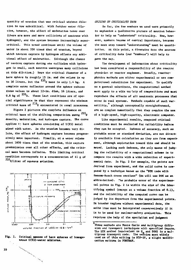
Figure 2 pictures the complete influence on235
critical mass of the shifting competition among U
density, moderation, and hydrogen capture. The curve
applies tt bare spheres consisting of U(93) metal
mixed with water. As the uranium becomes very di-
lute, the effect of hydrogen capture becomes progres-
sively more important. Finally, at a water volume
about 1600 tines that of the uranium, this capture
predominates over all other effects, and the criti-
cal mass becomes infinite. This limiting critical
condition corresponds to a concentration of 11 g of
U/liter of aqueous solution.
| 2 3 S O tfens'ty apcreasing: .
ORIGINS OP CRITICALITY DATA
So far, the few numbers we used were primarily
to emphasize a qualitative picture of neutron behav-
ior to help us "understand" criticality. Now, how-
ever, numbers become of central importance, because
the next step toward "understanding" must be quanti-
tative. At this point, a diversion into the sources
of criticality data (our "numbers") will help to
pave the way.
The development of information about criticality
has been considered a responsibility of the reactor
physicist or reactor engineer. Broadly, reactor-
physics methods are either experimental or are com-
putational substitutes for experiment. To qualify
as a general substitute, the computational method
must apply to a wide variety of compositions and Bust
reproduce the effects of all neutronic processes that
occur in real systems. Methods capable of such ver-
satility, although conceptually straightforward,
are so complex numerically that they require the use
of a high-speed, high-capacity, electronic computer.
Like experimental results, computed critical
conditions must be evaluated for reliability before
they can be accepted. Indexes of accuracy, such as
probable error or standard deviation, are not direct-
ly available from calculation as they are from experi-
ment, although exploration toward this end should be
noted. Lacking such Indexes, the only means of judg-
ing the reliability of a computational scheme is to
compare its results with a wide selection of experi-
mental data. In Fig. 2 for example, the points are
derived from experiment, and the solid curve Is com-
puted by a technique known as the "DTK code with
Hansen-Roach cross sections" (We will use DTK as an
abbreviation). The probable error of the experimen-
tal points in Fig. 2 is within the size o£ the iden-
tifying symbol (except at a volume fraction of 0.1),
and the reliability of the computed curve can be
judged by its departure from the experimental point*.
In broader regions without experimental data, the
solid line must be Interpreted conservatively if it
is to be used for nuclear-safety evaluation. This
requires the help of the specialist and judgment
O.OOOl Q001 0.01 01 >0
volume traction 0< U(93) 01 IB.6 ' 'cm1
Fig. 2. Critical masse* of bare spheres of homoge-neous U(93)-water mixture*.
These methods are Monte Carlo and multlgroup diffu-sion and transport techniques with specified input*.The DTK method (equivalent to S Q and DSN) is a mul-tigroup transport code. The version most widelyused as of this writing is DTF-IV, a slight modifi-cation written in FORTRAN.
10

O O from experimentcomputed (DTK)altei 5^>'"'"i1 Im o t i v e l i m i t s I | T T j ^ - ^ ' ^ - " ' i \\\
i! - <^<n i i ! IN
001 O.Ivolum* fraction of U(93) at 18.8 fl/cm*
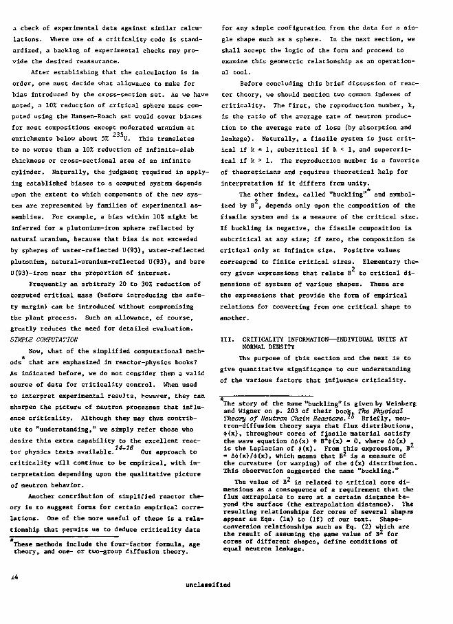
Fig. 3. Alternative safety limits for critical mas-ses of bare spheres of U(93)-water mixtures.
based on his experience and insight. The reasonable-
ness of his conclusions, which he should attempt to
make apparent, can be decided in any of a number of
ways.
For example, not long ago the experimental
points for bare, water-moderated spheres appeared as
in Fig. 3 Instead of as in the more modern Fig. 2.
Throughout a large region of higher uranium concen-
trations the computed curve (solid) had little ex-
perimental support. The three dotted curves show
various ways in which the computed curve could then
be scaled down for nuclear-safety application.
Curve 1, which carries a constant fractional shift
throughout the unsupported region, was not consid-
ered conservative enough. Curve 3, at the other ex-
treme, is too conservative because it levels off ab-
normally where critical mass is known to be increas-
ing. Even without much insight, however, the more
carefully selected curve 2 appears reasonable. At
this point, it is worth noting the influence of the
recent experimental points that appear in FI3. 2 but
not In Fig. 3. It turns out that curve 1 of Fig. 3
is adequately conservative, although this should not
Note that unreflected spheres are useful for nuclear-safety application only if effects of evpr-presentreflection are superposed. A more realistic exam-ple, which would Involve water-reflected spheres,happens to be a less clear illustration.
have been assumed in advance. Thus, the difference
between curve 1 and curve 2 represents an "ignorance
factor" that was removed by the new experimental in-
formation.
This Illustration is typical of a situation
that will confront us time after tine when experi-
mental information is inadequate. In later discus-
sions we will have to use computed data, both for
illustration and for nuclear-safety application.
Unless specifically stated otherwise, the DTK tech-
nique with Hansen-Roach cross sections will be re-
presented, because its results have been compared
abundantly with experiment.
TYPICAL DETAILED COMPUTATIONAL TECHNIQUES
A credibility gap should be expected whenever *
calculated number is simply handea from one person
to another Tor criticality safety guidance. In addi-
tion to the question of inherent accuracy of the cal-
culation, how does the user know that there ha* been
no input error or machine error? Our first sugges-
tion is that the user have some acquaintance with
the capability of the computational technique.
DTK. As one example, let us consider the DTK code
with Hansen-Roach cross sections. " This "trans-
port" code describes the probable behavior of a
large population of neutrons within a system of ele-
mentary geometry. The description is la terms of an
adaptation of the integral equation that Boltzaann
developed for problems of gas dynamics which are
similar to neutron-transport problems but even more
complex. The simplified Boltzmann equation is inte-
grated numerically, giving relative values for gain
of neutrons by fission and for loss of neutrons by
capture and leakage to a precision that is United
only by machine capacity and available running time.
A principal option of DTK adjusts dimensions to bal-
ance neutron gain and loss, thus establishing crit-
ical size.
As contrasted with precision, the accuracy of a
DTK result is controlled by the cross-section set
that is part of the problem input (the rest of the
input describes the geometry and composition). Neu-
tron cross sections of an isotope give the probabil-
ities of various neutron interactions with that Iso-
tope, namely, capture, fission, and scattering (with
Another common option establishes the neutron re-production number, k, for a system of fixed sice.
11

or without energy loss). They depend upon neutron
energy, and for DTK are given as average values for
each of a limited number of neutron-energy subdivi-
sions or "groups."
The Hansen-Roach cross-section set has 16 of
these neutron-energy groups. The virtue of this rel-
atively old, but stable, set for safety purposes is
that it has been used to check almost all appropri-
ate experimental critical masses. ' ' Thus biases
of results are known for critical systems with a
wide range of composition, and they can be estimated
for most new compositions. In brief, calculated and
experimental critical masses agree to better than
10% (a value smaller than usual safety margins) for
spheres of uranium at enrichments of about 5% 235U
or greater in combination with many other materials233
and for hydrogen-moderated plutonium or U, either
bare or water-reflected. Nonconservative biases
(calculated values too large) occur for hydrogen-
moderated uranium with enrichments below about 5%.
Discrepancies of about 15% are found with 2% enriched
uranium, and results deteriorate further at still
lower enrichments, showing about 30% discrepancy for
U(l,4). Although improved agreement would be ex-
pected of an up-to-date cross-section set, the bur-
den of reestablishing biases has prevented modern-
ization of the generally adequate Hansen-Roach set.
A limitation of DTK is that it handles only the
one-dimensional geometries, spheres, infinitely long
cylinders, and slabs of infinite extent. In addi-
tion to individual units of these shapes, a "cell"
option of the code covers infinite lattices that can
je approximated by close-packed spheres or by close-
packed cylinders of infinite length. Practically,
the geometric limitation of DTK is not so severe as
it might seem, because results may either lead di-
rectly to conservative safety limits for other forms
that fit into the calculated geometric envelope, or,
as we shall see in the next section, be converted
empirically to apply to shapes such as finite cylin-
ders and parallelepipeds.
The essential simplicity of one-dimensional
forms is that the average behavior of neutrons de-
pends upon only the neutron energy, the materials
encountered, and a value of angle at which each sur-
face is crossed. (Location on the surface ,ed not
be considered because all such points for a sphere,
infinite cylinder, or infinite slab are equivalent.)
For other forms, behavior depends upon the location
of the surface crossing as well as its angle, which
greatly complicates numerical solution. Although
two- and three-dimensional transport codes have been
developed, they either require long computing time
on machines with large storage capacity, or involve
relatively crude geometric and cross-section approx-
imations. For criticality-safety applications, such
codes do not generally compete with the Monte Carlo
techniques that we will consider next.
Monte Carlo. Instead of treating the probable be-
havior of a large neutron population directly as do
transport codes, the Monte Carlo technique mathemat-
ically traces the paths of individual neutrons, col-
lision by collision, until their disappearance be-
cause of processes such as absorption and leakage.
Changes of energy, direction, and position from one
collision to the next are governed by probability
distributions that are derived from tables of cross
sections vs neutron energy. These distributions are
sampled statistically to establish the successive
steps in each path. The result of superposing many
such neutron histories simulates an extremely low-
power critical experiment, even including the mean-
derings of neutrons throughout the assembly.
An advantage of Monte Carlo over transport
methods is that it is inherently less limited by ge-
ometry; the computing effort required to track neu-
tron paths is relatively insensitive to geometric
complexity. As a result, Monte Carlo can handle any
geometry, generally as an assemblage of cells—for
example, finite cylinders and hemispheres, or com-
binations thereof, and readily accommodates finite
arrays of units.
As must be suspected, straightforward Monte
Carlo simulation would usually require impossibly
great machine capacity and computing times. But
clever sampling tricks and weighting techniques to
emphasize the most important interactions have made
the method practical for a Targe variety of systems,
;:hough it is still a more expensive type of calcula-
tion than DTK. For criticality calculation, Monte
Carlo efficiency decreases with increasing modera-
tion because of the many scattering steps required
for significant reductions of neutron energy.
Most Monte Carlo codes are equipped to use de-
tailed cross-section information Instead of neutron-
energy-group averages. One Oak Ridge version known
12

12as KENC, however, uses the DTK multigroup approach
with Hansen-Roach cross sections, largely to save
computing time when more detailed treatment is not
required. Many checks of experimental data by this
code confirm the biases established by DTK and indi-
cate that geometric complications do not influence
them. Assuming adequate precision, which depends
only upon the number of neutron histories considered,
it thus seems that the accuracy of KENO (as of DTK)
is governed by the cross-section set, not by the
numerical manipulations.
This brief discussion of representative trans-
port and Monte Carlo criticality codes, and of the
Hansen-Roach cross-section set, is to remove some of
the mystery associated with mere names and to give
some fctling for their capabilities'and limitations.
We conclude that either DTK or KENO can provide re-
sults as good as the inherent accuracy of the cross
sections used, and that properly computed results
can be applied reliably when (as is usual) biases
introduced by the cross-section set can be estimated.
DTK is the cheaper end more convenient method when-
ever the needed information can be deduced from one-
dimensional results. KENO is appropriate for com-
plex geometry or arrays, but becomes expensive for
well-moderated systems. Other codes and cross-
section sets can be examined similarly, but may re-
quire special checks against experimental data to
confirm their applicability.
The Aooeptance of Computed Data. Knowing the capa-
bility of a computational technique is only a start
toward accepting a result as reliable. The most
common causes of failure to achieve that capability
are input errors (cross sections, material designa-
tions, or dimensions may be transcribed improperly),
or misapplication of techniques (to be Illustrated
later). Self-monitoring features of modern machines
usually inform the operator if machine errors occur.
Broadly speaking, the supplier of calculated
data should be able and willing to support the valii-
ity of the numbers he provides—to tell how he was
convinced that they are reliable. The user, of
course, should be a good enough judge of the support-
Ing arguments to understand their implications and
to guard against a "snow job." The ways in which
confidence can be established depend upon the exper-
ience and ingenuity of beth the supplier and user of
the data, upon similarity of results to experimental
data, and upon the nature of information in printout
sheets provided by the computing machine. There are
few real rules; rather there are primarily sugges-
tions, and illustrations based on calculations with
the DTK code and Hansen-Roach cross sections.
The printout, with which the supplier must be
familiar, reproduces input data (geometry, materials,
and cross sections) and the spatial and angular sub-
divisions used for numerical integrations, gives com-
puted neutron spectra for the various spatial re-
gions, and indicates formal completion of the prob-
lem (the degree to which convergence criteria are
satisfied). Thus, a simple but careful check of the
reproduced input data can eliminate input errors
(which are not uncommon). This reassuring check
need not be repeated for parts of input that carry
automatically through succeeding problems.
Other steps toward establishing confidence are
less specific. A simple-minded observation is that
results should look reasonable in terms of background
criticality data. As was not true earlier, there is
now usually a basis for a fair guess of what the an-
swer should be. Even better than judging the plaus-
ibility of a single result is the added possibility
of examining trends from a series of related calcu-
lations. For example, it is sometimes easier to es-
timate relative effects of simple compositional
changes than to estimate critical sizes. Therefore,
multiple calculations are often considered worthwhile
when only a single criticality value is actually
required.
Still other clues about the validity of a calcu-
lation tire given by the spectra that appear on the
printout—whether mean energy and shape are about
right, and whether spectral changes from one medium
to another (such as the energy decrease expected
when passing from a metal core into a hydrogenous
reflector) make sense. Spectral infomntion may be
especially useful when the calculated critical size
is suspect, for it may point out an undetected error.
The other main source of potential error is a
poor choice of spatial and angular subdivisions for
the numerical integration performed by the machine.
Although anyone experienced in criticality calcula-
tion will avoid such a difficulty alnost automatical-
ly, the user still has the right to be convinced that
his problem was not set up too crudely. Explanation
may serve, but the most satisfying demonstration is
13UNCLASSIFIED
a check of experimental data against similar calcu-
lations. Where use of a criticality code is stand-
ardized, a backlog of experimental checks may pro-
vide the desired reassurance.
After establishing that the calculation is in
order, one must decide what allowance to make for
bias introduced by the cross-section set. As we have
noted, a 10% reduction of critical sphere mass com-
puted using the Hansen-Roach set would cover biases
for most compositions except moderated uranium at235
enrichments below about 5% U. This translates
to no worse than a 10% reduction of infinite-slab
thickness or cross-sectional area of an infinite
cylinder. Naturally, the judgment required in apply-
ing established biases to a computed system depends
upon the extent to which components of the new sys-
tem are represented by families of experimental as-
semblies. For example, a bias within 102 might be
inferred for a plutonium-iron sphere reflected by
natural uranium, because that bias is not exceeded
by spheres of water-reflected U(93), water-reflected
plutonium, natural-uranium-reflected U(93), and bare
U(93)-iron near the proportion of interest.
Frequently an arbitrary 20 to 30% reduction of
computed critical mass (before introducing the safe-
ty margin) can be introduced without compromising
the plant process. Such an allowance, of course,
greatly reduces the need for detailed evaluation.
SIMPLE COMPUTATION:
Now, what of the simplified computational meth-
ods that are emphasized in reactor-physics books?
As indicated before, we do not consider them a valid
source of data for criticality control. When used
to interpret experimental resuJts, however, they can
sharpen the picture of neutron processes that influ-
ence criticality. Although they may thus contrib-
ute to "understanding," we simply refer those who
desire this extra capability to the excellent reac-
tor physics texts available. ~ Out approach to
criticality will continue to be empirical, with in-
terpretation depending upon the qualitative picture
of neutron behavior.
Another contribution of simplified reactor the-
ory is to suggest forms for certain empirical corre-
lations. One of the more useful of these is a rela-
tionship that permits us to deduce criticality data
These methods Include the four-factor formula, agetheory, and one- or two-group diffusion theory.
for any simple configuration from the data for a sin-
gle shape such as a sphere. In the next section, we
shall accept the logic of the form and proceed to
examine this geometric relationship as an operation-
al tool.
Before concluding this brief discussion of reac-
tor theory, we should mention two common indexes of
criticality. The first, the reproduction number, k,
is the ratio of the average rate of neutron produc-
tion to the average rate of loss (by absorption and
leakage). Naturally, a fissile system is just crit-
ical if k = 1, subcritical if k < 1, and supercrit-
ical if k > 1. The reproduction number is a favorite
of theoreticians and requires theoretical help for
interpretation if it differs from unity.
The other index, called "buckling" and symbol-2
ized by B , depends only upon the composition of the
fissile system and is a measure of the critical size.
If buckling is negative, the fissile composition is
subcritical at any size; if zero, the composition is
critical only at infinite size. Positive values
correspcnd to finite critical sizes. Elementary the-2
ory gives expressions that relate B to critical di-
mensions of systems of various shapes. These are
the expressions that provide the form of empirical
relations for converting from one critical shape to
another.
III. CRITICALITY INFORMATION—INDIVIDUAL UNITS ATNORMAL DENSITY
The purpose of this section and the next is to
give quantitative significance to our understanding
of the various factors that influence criticality.
The story of the name "buckling" is given by Weinbergand Wigner on p. 203 of their book. The PhysicalTheory of Neutron Chain Reactors. ° Briefly, neu-tron-diffusion theory says that flux distributions,<t>(x), throughout cores of fissile material satisfythe wave equation A$(x) + B cj> (x) - 0, where A*(x)is the Laplacian of $(x). From this expression, B- &<t>(x)/t(x), which means that B2 is a measure ofthe curvature (or warping) of the 4>(x) distribution.This observation suggested the name "buckling."
The value of B2 is related to critical core di-mensions as a consequence of a requirement that theflux extrapolate to zero at a certain distance be-yond the surface (the extrapolation distance). Theresulting relationships for cores of several shapesappear as Eqs. (la) to (If) of our text. Shape-conversion relationships such as Eq. (2) which arethe result of assuming the sane value of B2 forcores of different shapes, define conditions ofequal neutron leakage.
J.4unclassified

The emphasis Is on data that contribute to this ob-
jective as opposed to comprehensive coverage of crit-
icality information. For a reasonably complete col-
lection of experimental critical-mass data, see AEC
report TID-7028, "Critical Dimensions of Systems
Containing U 2 3 5, Pu 2 3 9, and u 2 3 3." 1 7 Although we
assume that TID-7028 will be generally available, we
have reproduced some of its more essential figures
as our Appendix.
Because of the gaps that exist in experimental
data, results of calculation must be used for many
of our illustrations. As mentioned before, these
computed data should be evaluated for reliability
before being used for nuclear-safety purposes. In
many cases, existing compilations of computed vs ex-
perimental critical sizes will be adequate for such
an evaluation.
In the course of illustrating influences on
criticallty, we shall discuss several generally use-
ful empirical relationships. Here, more than usual
detail will be included in the expectation that
these relations can become practical tools of all
who are concerned with criticality control. The
first of these empirical tools is the scheme for
shape conversion.
RELATIONSHIPS FOR SHAPE CONVERSION
Expressions that derive from simple reactor
theory relate buckling, B , end the dimensions of
critical cores of fissile material of easily de-
scribed shapes. " As In each case that follows,
the actual dimension is augmented by a so-called ex-
trapolation distance, 6, which we will discuss
further.
For a sphere of critical radius r ,
(la)
For a parallelepiped of critical dimensions
from which the expression for a critical cube of
side hx la
(lc)
For a cylinder of critical radius r and crit-cleal height h c.
7
6
3
2
I T
jr±
—
t
... I
WATB*REFL£CTED(W6"A1I
- H/U-23S»44O H/U-23S'32O(NORMAUZED)X SPHERE VALUES
•*- —
—-INFINITE SLAB
BAREII/IS'AI)
> - - •
I"—
INFINITE CYLINDER 7—ai 02 03 S3 35 O6 or O B 6 3 To
h/tt/(l+h/d)
Fig. 4. Extrapolation distances for shape conversionof U(93) solutions. The curves apply tocylinders of height h and diameter d.
B(Id)
In the special case of an Infinitely long cylinder
of critical radius r ,
BVc 7"
(le)
and for an infinite slab of critical thickness h (a
cylinder of infinite radius), the buckling becomes\2
(If)(hc IFor any given fissile composition, we recall2
that B is a constant, so these various geometric
expressions for B can be equated. And, according
to simple theory, the "extrapolation distance," S,
is a constant for each type of reflector that sur-
rounds the fissile material. Actually, experiments
that have compared various critical shapes of a fixed
composition show that the quantity S Is not quite
constant, but depends somewhat upon the shape. The
way in which S varies with the elongation of criti-
cal cylinders is shown by Figs. 4 and 5, taken from
TID-7028. The shape of each cylinder is charac-
terized by the ratio of its height to Its diameter
(h/d). To avoid infinitely long curves, however, &
appears in the figures as functions of (h/d)/(I +
h/d) so that the abscissa zero corresponds to a slab
of infinite diameter, and unity corresponds to a
cylinder of infinite length.
Figure 4 applies to 11(93) solutions, the upper
curve to water-reflected cylinders, and the lower to
essentially bare cylinders. Data for more limited-
IS
O 01 02 0.3 04 O.5 06 0.7 0.8 09 1.0
Fig. 5. Extrapolation distances for shape conver-sion of U(93.5) and plutonium metal. Thecurves apply to cylinders of height h anddiameter d.
families of cylinders suggest that the lower curve
of Fig. 4 also applies to U and Fu solutions
(with concentrations similar to those indicated for
U), and that the upper curve may be used for U
solutions if scaled by the factor 5.1/5.9, and for
Pu solutions if scaled by the factor 5.7/5.9.
The other experimentally established values of
extrapolation distance apply to U(93) metal and plu-
tonlim metal, and appear in Fig. 5. This leaves
uncertainties about appropriate values of 6 for slur-
ries and damp compounds that are intermediate be-
tween the dry metal and solutions, about very dilute
solutions, and about any homogeneous mixture of ura-
nium at reduced U enrichment. Here, it is neces-
sary to resort to results of conservative calcula-
tions until further experimental data become avail-
able. Sometimes two components of the extrapolation
distance for a reflected system may be estimated
separately. A value 6 , from the upper curve of
Fig. 4, for example, may be viewed as consisting of
the extrapolation distance for the bare cylinder of
the sane shape, 6Q (from the lower curve), plus a
quantity, 6 , that depends only upon the reflector
and is called "reflector saving." If *t • «o + S
T
i» desired, 6 may be known and 6 computed, or vice
In some literature, terminology is confused by useof the term "reflector saving" to nean £ Instead
versa. Values of reflector saving that apply to hy-
drogenous mixtures of uranium at enrichments of less235
than 932 U may be derived, for example, from Fig.
Al in the Appendix. The reflector saving of water
is simply the difference between critical radii of
corresponding unreflected and water-reflected
spheres.
Of course, the value of the ability to convert
from one critical shape to another is that c-ltical
data for a single, simple shape such as a sphere may
be applied generally. Thus the sphere, which appears
so seldom In process equipment, actually represents
other more practical shapes. (As an alternative to
actual shape conversion, critical masses and volumes
of spheres, which are minimum values, may be applied
conservatively to other shapes.)
Some examples will clarify shape conversion by
means of Relations (1) and empirical values of ex-
trapolation distance. Suppose that we wish to see
how trii critical diameter of elongated cylinders
chaigis with h/d for a water-reflected solution con-
taining 500 g of 11(93)/liter. At this concentration,
chosen because it represents the minimum critical
size for solutions, the radius of a critical water-
reflected sphere is known to be 11.5 cm. Combining
Eqs. (la) and (Id), we have
(2)
where the dimensions (including 6) on the left apply
to a critical sphere, and those on the right apply
to a corresponding critical cylinder for which h/d -
h /2r . With r - 11.5 cm and 6c c s aFig. 4), Eq. (2) becomes
2.405
5.9 cm (from
H ( h / d ) + 2 v 0.0325. (3)
- ) , Fig. 4
6.35 cm, and the value r » 7.0 en satis-
For the infinitely long cylinder (h/d
gives S
fies the above relation. Continuing with finite
values of h/d, Eq. (3) may be solved by trial to
give the results shown in Table II for various elon-
gated cylinders.
16

TABLE II
CRITICAL ELONGATED WATER-REFLECTED CYLINDERS OFU(93)02F2 SOLUTIONS AT 500 s OF
235U/LITER
h/d. , , , » Crit. volumeV C m ) rc(cm) d(in.) (liters)
10
5
3
2
6.35
6 .2
6 . 1
6 .0
5.95
7 .0
7 .2
7 .5
7.9
8 .5
5 . 5
5 .7
5 .9
6 .2
6 .7
23.6
13.2
9 .4
7.7
sphere: 6.4
Two features of this listing are worth pointing
out. First, the value of the critical diameter of
the infinitely long cylinder is not overly conserva-
tive when assumed for cylinders with height-diameter
ratios as small as 5. This observation is useful
where interest is in a long cylinder for which no
experimental critical data exist, so that resu]ls of
computation must be relied upon. The value for an
infinite cylinder is much easier to compute than
that for a finite cylinder, and, as just shown, it
is almost as good. The second feature is that there
is not much advantage over using the sphere critical
volume until the cylinder height becomes several
times its diameter. (The volume of the critical
equilateral cylinder is about the same as that of
the sphere.)
In the particular case of the infinite cylinder,
the unreflected critical radius is obtained simply
by adding the reflector saving to the water-reflected
critical radius. For the first item of Table II,
the reflector saving is «c(refl) - «c(bare) - 6.35 -
2.25 (from Fig. 4); so the critical radius of the
bare infinite cylinder is 7.0 + 4.1 - 11.1 cm, and
the critical diameter is 8.7 in. Again, we remind
ourselves that there is always some reflection, so
the bare dimension is of little practical value ex-
cept as a reference point. There are situations,
for example, In which reflection is small enough
that an average of the bare and reflected diameters
would be appropriate for criticality control. There
can be other instances in which the critical diam-
eter of a long, bare cylinder is extablished! exper-
imentally and the reflector saving of water can be
estimated. Then the critical radius of the water-
reflected cylinder will be approximated by subtract-
ing the reflector saving from the bare radius.
TABLE III
CRITICAL SQUAT WATER-REFLECTED CYLINDERS 0?U(93)0oF. SOLUTIONS AT 500 g OF
235U/LITER
. . . , , . , /j \ Crit. volumeh/d V c m ) h c ( c m ) hc ( l n' ) (liters)
0 6.6 4.3 1.7
0.05 6.45 5.0 2.0 39.5
0.1 6.35 6.0 2.4 17.0
0.3 6.1 9.6 3.8 7.8
0.5 5.95 12.8 5.0 6.6
sphere: 6.4
Interest in critical squat cylinders (or slabs)
of solution is stimulated largely by the use of shal-
low pans to catch material that may leak from equip-
ment. Here the critical depth of solution is impor-
tant, so, to continue Table II for small height-
diameter ratios, it is convenient to rewrite Eq. (3)
- 0.0325 (4)
In this case, the simple solution of this equation
is for a slab of infinite diameter (h/d « 0): Fig-
ure 4 gives S •= 6.6 cm and h = 4.3 cm or 1.7 in.
Again, the above relation must be solved by trial
for finite diameters. Typical results are shown in
Table III.
In this case, too, the critical volume does not
increase significantly until the diameter becomes
several times the height. Now, the thickness of the
bare infinite slab is obtained by adding twice the
reflector saving from Fig. 4 to the water-reflected
value (to remove the effect of water on each side of
the slab). The result, about 4.7 in., is again
largely of academic interest. On the other hand, a
semireflected slab simulates the usual catch pan
that is reflected only on its base. The appropriate
critical thickness, obtained by adding only a single-
reflector saving to the value for full reflection,
is then 3.2 in.
As mentioned, Tables II and III apply to a con-
centration at which solution critical dimensions are
minimum, so they may be used as conservative esti-
mates for other concentrations. Furthermore, crit-
ical parameters of the uranyl-fluoride solution are
slightly smaller than those of the nitrf.te or other
17

4 3
4 0
3 9
3 0
25
20
<
\
•'•>
V.1-
\
1
~ ^ 4-
i
^-h:
i~
1BsC
--H-
t)DjO
i
—
>grophi
~ — I —
• tCS-3
z•—i
10 12 14 16 18 Z0 ZZ
Fig. 6. Critical masses of U(93.5) metal spheresin various reflectors; p(U) = 18.8 g/cm .
common aqueous solutions. Thus the dimensions in
these tables provide a generally useful basis for235
evaluating the nuclear safety of U solutions in
isolated containers.
EFFECTS OF VARIOUS REFLECTORS
Water, the neutron reflector discussed so far,
happens to be representative of reflection effects
usually encountered in a processing plant. Figure 6
(taken from TID-7028) shows the most complete exper-
imental set of comparisons of different reflector
materials. The curves apply Co various thicknesses
of reflector surrounding spherical U(93) metal. Al-
though the magnitudes of effects differ for other
fissile compositions and other core shapes, the ap-
propriate curves scale similarly to those of Fig. 6.
He note that the reflectors that are much better
than water at considerable thicknesses (beryllium,
beryllium oxide, heavy water, graphite, uranium, and
pure nickel) are uncommon materials except in cer-
tain reactors. Other than keeping in mind the unusu-
al effects of these special reflectors, we assume
that they need not be considered in normal operations.
Concrete, not represented in Fig. 6, is both
common and a somewhat better reflector than water.'
It is unusual, however, to have concrete fitted
closely about fissile material, and the customary
concern is about the reflection effect of concrete
when it is separated by a number of inches from the
18
19object it influences. Lloyd and Clayton at Hanford
measured the effect of a 6-in.-thick shell of con-
crete surrounding a 14-in.-diam sphere of plutonium
solution but separated from it by a 4-in. gap. They
observed that reflection by this concrete was about
equivalent to that of a 1-in.-thick, close-fitting
layer of water. The effect of a 12-in.-thick con-
crete wall against a 9-in.-diam cylinder of U(93)235
solution (330 g U/liter, unreflected critical
height 23 in.), even more like plant conditions, was20
investigated by Fox, Gilley, and Callihan of OKNL.
Their results indicate that reflection by the wall
was less than that of a 0.2-in.-thick, close-fitting
layer of water. When the wall is 6 in. away from
the cylinder, its influence is reduced by another
factor of 3 or A, and so is negligible for practical
purposes.
Steel, as used in forming dies or pressure ves-
sels, and water are the principal reflector materials
that are likely to be both close-fitting and thicker
than a fraction of an inch. (Low-density thermal
insulation is a poor reflector, so it is not in the
same class.) Because of the pronounced effect of
spacing, we conclude that structures of good reflec-
tor material such as concrete are hardly ever more
effective than close-fitting water. Relative crit-
ical volumes of different fissile (.ores surrounded
by various thicknesses of water are shown in Fig. A2.
It is apparent from Fig. 6 that water has unusu-
al features as a reflector. At thicknesses up to an
inch or so, it is among the more effective materials,
but an increase of thickness beyond several inches
adds little to its influence. (For shapes such as
long cylinders or slabs, the "saturation" thickness
is somewhat greater than that for the small spheres
of Fig. 6.) This peculiar behavior of water is a
consequence of neutron moderation and subsequent
capture by hydrogen. After passage through several
inches of water, the average neutron has so little
energy that it is more likely to be captured by hy-
drogen than to find its way back to the fissile core.
We should make it clear that we us,. <:he term
"water-reflected" here to imply that the fissile
system of concern is closely surrounded by at least
6-in.-thick water. Thus the reflection effect la
essentially the maximum attainable with water.
We stated earlier that fissile objects as well
as inert materials may be viewed as neutron reflectors.
16

critical thickness of solution annuluswithout axial cylinder
4 6 8 10d,gap bstwten solution cylinder and annulus,in.
Fig. 7. Computed critical radius of solution cylin-der vs distance to surrounding annulus ofvater or of solution. The cross section ofthe solution annulus is one-half that ofthe annulus which is critical without theaxial cylinder (i.e., critical thicknesst - 2t at fixed r + d).c c
This point is illustrated by Fig. 7 which gives com-21
puted (DSN) critical radii of infinitely long cyl-
inders of U(93) solution at 500 g of 235U/liter.
Curve A shows how the critical radius increases as a
6-in.-thick annulus of water is moved outward from
the cylinder. Curve B is similar, except that a
thinner surrounding annulus contains the same solu-
tion as Che central cylinder. For each configura-
tion, the cross section of the solution annulus is
adjusted to be one-half that of the unreflected
critical annulus of the same inside diameter (the
dotted curve). For spacings greater than 2 in., the
two curves are surprisingly similar. At a spacing
of 7 in., the reflector saving of either annulus is
just one-half that of close-fitting water.
Qualitatively, it is clear why a gap between a
fissile core and surrounding material has such a
pronounced effect. As spacing Increases, the core
simply becomes a poorer and poorer target for neu-
trons scattered back from the reflector. This pic-
ture also showa why the influence of a gap around a
spherical core is greater than that of the same gap
about a corresponding long cylinder or thin slab of
similar material. The sphere is the poorest target
for returning neutrons, the cylinder is somewhat
better, and the slab intercepts still more of the
reflected neutrons.
MORE ABOUT SOLUTIONS AND MIXTURES
The homogeneous U(93) metal-water mixtures Il-
lustrated in Figs. 2 and 3 are, of course, not en-
countered in practice. The "experimental" valuea In
these figures were derived by applying small correc-
tions to results for uranyl-fiuoride solutions, and
these corrections become negligible for U concen-
trations below 200 g/liter (or for volume fractions
of uranium metal below 0.01). In other words, crit-
ical dimensions of hypothetical metal-water mixtures
and of solutions coincide over the concentration
range of most interest for aqueous processing. (See
Figs. A3-A6 for U(93), Figs. A7-A10 for plutonium,
and Figs. A11-A14 for 233U.) However, as 2 3 5U con-
centrations increase, particularly beyond the solu-
tion range, deviations of practical mixtures from
metal-water become increasingly significant.
The fictitious mixture is used as a reference
composition because its critical mass is ainlmua at235
a given water- U ratio. This follows because the
U density is greater in the metal-water mixture
than it is in a water mixture of any uranium com-
pound at the same H/ U atomic ratio. Little ex-
perimental criticality information exists for the
range of composition that Includes aqueous slurrlea
and filter cakes. Here, metal-water values aay be
applied conservatively for nuclear-safety evaluation.
Computed critical masses of several U(93)-w»ter
mixtures in the form of water-reflected spherea ap-
pear in Fig. 8. The abscissa represents 0 densi-
ty, and the curve at densities less than 0.8 kg of
U/liter applies to uranyl-fluorlde solutions. At
the right, the upper curve Is for mixtures of OF,
and water, the middle curve applies to UO.-water, and
the lower curve gives metal-water reference values.
The atomic ratios, H/ 35U, H/Pu, and H/ U areused as indexes of the degree of hydrogen modera-tion. Collectively, these ratios are frequentlydesignated H/X, where X represents 2 3 5 0 , Pu, or233U. Relations between H/X and density of X forcertain solutions, metal-water mixture?, and soaeother mixtures are given In Table I and Fit. 12 ofTID-7028.
19

200
10080
GO
4 0
20
•0
8
4
2J
j
' j
- • —,
|
40.—i
¥...-
utt Un1 iPUO,.«ol«r
if4+
T "
| D < J-M Oli
. 1 j —
,
r
1
I—
i i (
O.I O.2 0.4 CLO 10 2 4 6 10 SO 40 CO 100
U-233 density, kg U-235/lil«r
Fig. 8. Computed critical masses of water-reflectedspheres of mixtures of water with U(93.5)metal, U(93.5)02, or U(93.5)F4.
The principal purpose of this illustration is to
show the penalty that can be paid if metal-water
values are asaumed for practical mixtures. But we
should add that this penalty sometimes may be out-
weighed by the uncertainties of calculated results.
As the greatest differences in Fig. 8 are for
dry (unmoderated) materials, it is instructive to
examine a greater range of compounds under this con-
dition. In Fig. 9, UC2, U02F2, and UFfi (condensed)
have been added to the three materials shown in
Fig. 8. Critical masses apply to «ater-reflected
spheres of the undiluted fissile compound at crystal22
density. The curve refers to unmoderated U(93)235
metal at various U densities. Departures of crit-
ical masses of compounds from the line show that the
' 'U density is not the whole story, and that the
carbon, oxygen, and fluorine atoms have some influ-
ence on critical size. (Note that deviations from
the curve are roughly proportional to the number of
diluent atoms per uranium atom.) Although these at-
oas are too few to have a significant moderating ef-
fect, their nuclei do scatter neutrons so that the
atons near the outside of the core return toward the
center some neutrons that would otherwise pass into
the surrounding water. The effect Is like that of
an added Internal reflector.
1000900BOO700
eoo
500
400
300
S too
D
E100
o 90~ SOw 70u
90
30
\\\
\\
\
di
\
*
J,oT0
V_U(93) metol.
\uo,.
r°*
\\
*
O.I 0.2 0.3 0.4 0.9 0.6 OS 1.0
/>(U)/I8.75
Fig. 9. Computed critical masses of water-reflectedspheres of U(93) compounds. The line ap-plies to U(93) metal at various fractionsof normal density.
Measured effects of diluting U(93) and plutonium
metal with other materials are given by Figs. A15 and
A16, and by Ref. 23. Figure A16 is particularly in-
teresting because it shows that carbon atoms mist be
present in large proportion to moderate neutrons
significantly. The other effective moderating mate-
rials, deuterium, beryllium, and beryllium oxide,
shown by this figure, are encountered alaost exclu-
sively as reactor components. (Graphite, of course,
is also used for crucibles and molds in casting
furnaces.)
Part of the scattering effect of fluorine is com-pensated by capture of very high-energy neutronssuch as occur in the unmoderated systems of Fig. 9.
Note that these moderating materials lead to amallcritical masses at very low 2 3 5U densities. (Deu-terium, beryllium, carbon, and oxygen do not cap-ture neutrons as readily as does hydrogen, ao the/do not poison very dilute 235U.) Although 235ucritical Basses may be small, the correspondingvolumes are large.
20
The need to process reactor-fuel compositions
such as U-graphlte and U-BeO leads to concern about
critical masses of the mixtures U-graphite-H.O and
U-BeO-H2O. Excepting some data for U(93)-graphite-
plastic compositions, there is no experimental in-
formation about these ternary mixtures. (Perhaps
"fourfold mixtures" is the better term, because the
uranium enrichment may be less than 937 Z35U, which
leads to 235U-238U-graphlte-H20 and 235O-238U-Be0-
H»0. The situation, of course, becomes even more
complex when plutonium is built into the fuel.) In
the particular case of U(93)-graphite-H20, there is
a computational survey by Stratton5'24 of Los Alamos.
His results for unreflected spheres are reproduced
in Fig. 10. This family of curves illustrates the
complex trade-off among effects of density change,
scattering and moderation by graphite, and modera-
tion and capture fcy hydrogen.
The power-reactor fuel that la presently seat
abundant is U02~ U(>2 (if fuel-cladding materials
are Ignored), which Implies that criticality data
for the ternary system 235U02-Z38U02-H,0 arc of ex-
tremely practical interest. Appropriate to this com-
bination are experimental critical dimensions of ho-
mogeneous mixtures of hydrogenous material and ura-
nium at enrichments of less than 93Z U, which
appear In Figs. Al and A17. (Sea Ref. 25 for a com-
putational survey.) It is apparent from these data
that U behaves like a neutron poison whan It Is
present In much greater abundance than U. In
fact, uranium containing less than 1.0Z 0 cannot
be made critical as a homogeneoua mixture with watar
or other hydrogenous material.
HETEROGENEOUS URANIUM-WATER SYSTEMS
Of course, many nuclear-aafaty questions about
the customary fuels for reactor lattices cannot be
( 0 = 1.90 g/cm3 : i/>(235UH7.6g/cm3 ^
U-235 density
Fig. 10. Computed critical masses of unreflected spheresof U(93.S)-water-graphlte mixtures.
UNCLASSIFIED
answered by information about homogeneous mixtures.
Certain fuel fabrication steps, storage, and trans-
portation may involve regular lattices of fuel ele-
ments in water; dissolving the spent fuel for re-
processing may involve either regular lattices or
random arrangements of chopped elements, but In
either case there is a mixture of solids and solu-
tions with changing composition. Considering the
range of materials that may be represented in vari-
ous fuel elements and processes (which can b& non-
aqueous), there are so many variables that critical-
icy data cannot be mapped comprehensively. Special-
ized data required for a given fuel can be obtained
most readily during development of the reactor for
which the fuel is intended. If this is not done,
there is the choice between applying very conserva-
tive nuclear-safety controls or obtaining specific
criticality Jata. Depending upon circumstances,
economy may dictate either alternative.
With the above choice in mind, it behooves us
to have some idea about how to establish "very con-
servative" controls. Most of the fissile material
in present power-reactor fuels in the United States
is uranium with U enrichments of 2 to 5%. (We
refer to fuels for boiling-water and pressurized-
water reactors.) For this class of fuel, a basis
for conservative criticality control is the consid-
erable experimental information about lattices of
slightly enriched uranium rods immersed in water,
One set of conclusions from measurements with
latticed uranium in water is summarized in Fig. A18.
In this figure, minimum critical masses of lattices
and of homogeneous mixtures (both water-reflected)
are compared over a range of U enrichments. Each
point on the lattice curve implies optimum rod diam-
eter, optimum spacing between rods, a near-spherical
lattice shape, and complete water reflection. The
••' is feature of this curve is that it falls be-
low the curve for homogeneous spheres at U en-235
richments of less than - 52. Above about 53! U,
minimum critical masses occur for the homogeneous
systems (which may be viewed as lattices in which
rod diameter is zero).
Our qualitative picture of neutron behavior
helps us to understand the reduced critical masses
of lattices at low enrichments. As mentioned before,238
neutron capture by U (its "poison" effect) drives235,
happens that neutrons of intermediate energy (par-238
tially moderated) are captured more readily by U
than are either high-energy fission neutrons (unmod-
erated) or neutrons of lowest energy (fully moderat-
ed or "thermal"). In a homogeneous system, neutrons238
are exposed continually to capture by U while be-
ing moderated. In a lattice, however, the typical
neutron from a fission in one rod travels through238
water that is free of U before reaching another
rod (or being returned). At "optimum" lattice geom-
etry, this average path through water is such that
some neutrons, which otherwise would be captured by238
U, are moderated sufficiently to escape this fate.
Thus, fissions are produced more efficiently than V
the system were homogeneous, so that the critical
mass is smaller.
Now, various stages of conservatism in the crit-
icality evaluation of fuel-rod lattices in water be-
come apparent.
• The extreme of conservatism would be to apply min-
imum criticality data for highly enriched uranium
(homogeneous systems).
• The minimum critical mass of all possible lattices235
at the appropriate U enrichment may be used.
Alternatively, the minimum critical dimensions may
be chosen from Figs. A19-A21.
• The guiding criticality data may be derived from
uranium-metal lattices similar to the lattices of
actual fuel. For example, they may be obtained
from the sources of the Information summarized in
Fig. A18.
• Data may be specific to the fuel-element lattice
of interest.
A generalization falling between the last two
alternatives is suggested by existing experimental
information for specific power-reactor fuel elements.
Figure 11, for example, applies to water lattices of
elements that were studied for use in pressurized-
vater reactors. * The lower curve of minimum
critical volume vs U enrichment is for unclad
uranium-metal rods and should be somewhat conserva-
tive for zirconium-clad UO- rods. The two points a-
bove are for stainless-steel-clad UO,. Because of
the relatively small ranges of fuel-element dimen-
sions that are suitable for water-moderated power
reactors, the data of FJ^. 11 will not be in great
error if applied to any rod-type U(2 to 5)02 elementthe homogeneous curve to infinity at 1.0% U. It with the appropriate cladding material. There are
22UNCLASSIFIED
s 300
iI
a U02.00I6" S3 clod0 UOj.0.021" 98 cladO U ntttol, uncladO U metal, computed
U enrichment, percent
Fig. 11. Minimum critical volumes of water latticesof low-enrichment uranium or UO, rods, aswater-reflected spheres.
no experimental data about corresponding lattices in
solutions of slightly enriched uranium, such as
•lght be encountered in pickling baths or fuel dla-
solvera.
Before leaving water lattices, let us consider
the data for U(94)-metal lattices shown in Fig. A22.
This figure indicates a large reduction of attain-
able critical mass as pieces of the highly enriched
metal become smaller. Another item may be mentioned:
The only experimental evidence about combinations of
fissile solids and fissile solutions applies to
U(93), and is represented by Figs. 25 and 26 of TID-
7028 and by references in the associated text.
MORE ABOUT POISONS
As we have mentioned, hydrogen and U capture
neutrons readily enough' to behave like mild neutron240
poisons ( Pu is similar). Of the elements in com-
mon uranium and plutonium compounds, carbon, oxygen,
and fluorine have ineligible poisoning effect, ni-
trogen is a mild poison, and chlorine is a moderate
poison. Among structural materials, aluminum has a
small neutron-capture effect, copper and the compo-
nents of steels are mild poisons, and glass is in-
fluenced by its boron content.
One method of controlling solution criticality,
mentioned In the discussion of accident experience,
is to add strong poisons to the fissile material.
The neutron poisons most suitable for this purpose
are boron, cadmium, and the rare earths, samarium,
europium, and gadolinium. Cadmium's strong capture
effect is limited to neutrons of very low energy
(highly moderated), so this material is most useful
for dilute aqueous solutions. As the other strong
poisons remain effective for neutrons of intermedi-
ate energy, they are more generally applicable. Of
course, boron is preferred over the rare earths be-
cause of its much lower cost. There Is no very ef-
fective poison for the unmoderated neutrons that are
typical of undiluted fissile metal and most dry
compounds.
Of the strong poisons mentioned, the experimen-
tal data of TID-7028 (pp. 46-48) apply exclusively
to boron. Three types of system are represented:
homogeneous mixtures such as soluble boron ia urani-
um solution, boron-containing solids distributed
throughout uranium solution, and boron solution in
lattices of fuel rods. In most cases the quantity
of boron required to prevent criticality in. any fi-
nite system is established. This is accomplished If
the reproduction factor of the Infinite system, k. ,
is unity.
The rather scant experimental information about
homogeneous mixtures cay be supplemented by the (DTK)
computed curves of Fig. 12.SS Atomic ratios B/X (X. 235,. 239_ 233...= U, Pu, or U)
24
to
for which k « 1 ara shown
1*
M>asa*0.4at
\\
\A
• —
\
U-2
\
S5-3.24 01 WU-2S5-
\
.. .."S8» 2>
\
u-a
\\
\\
Pii-
\
\
23
•
•
•
•
•
•
•
•
\l3Tta •
H/X
This is why critical dimensions of uranyl-fluoridesolutions are slightly smaller than those of uranyl-nltrat* solutions.
Fig. 12. Computed atomic ratios of boron to fissileisotope at which fa, - 1, for mixtures ofwater with U(93.2), 233U, or 2J9Pu (in theatomic ratios B/X and H/X, where X = 2 3 SU, '23iu or 239PU).
23

2 6
2.1
2 2
2.0
i.a
- 1.6
• 14
"* o
oe
0 . 6
0 . 4
0 2
n
1
\
1j1II
I\\\\1
)
\y1ift\\\
V\\\
1
ii t
•
\
\
\
P«-239\
•
s
•
; 31
•. _-- ^"^
=: ...
" 10*
• ~ —
" - • » .
1
= = =
*
Fig. 13. Computed atomic ratios of cadmium to fis-sile isotope at which k_ » 1, for mixturesof water with U(93.2), 233o, or 239pu (lnthe atomic ratios Cd/X and H/X, where X =235Uf 233Dj or 239 P u ) >
for solutions of U(93), 239Pn, and 2 3 3D. Qualita-
tively, a greater proportion of boron is required
for 239Pu and 2 3 3U solutions than for 2 3 5D, to over-
come the more efficient fissioning of these materi-
als. Figure 13 shows results of similar calculations
for cadmium-poisoned solutions. The effect of cad-
mium decreases rapidly as the solutions become so
concentrated that very low-energy neutrons disappear.
A convenient means :f poisoning a solution Is
by packing the container with raschig rings of boro-
silicate glass. A tabulation os: experimental condi-
tions for which k^ » 1 with glass ln U solutions
appears on p. 47 of TID-7028. To illustrate an In-
fluence of the heterogeneous distribution of boron,
that table nay be extended as ln Table IV. The
listed overall B/235U ratios for k^ » 1 are expected
to be greater than corresponding values from Fig. 12,
TABLE IV
CONDITIONS AT WHICH k_ - 1 WITH S 1.5-ln.-o.d.GLASS RASCHIG RINGS IN 11(93) SOLUTION
VolumeTractionof Glass
0.24
0.22
0.24
2 3 5U Content ofSolution
K235P/Liter
385
385
67
hexogonol loiticeo 0.3"d u, BNLO 0.39"d U, Hon«om• 0.93"d U, Hanlord
— XX \ —A
40 60 SO 100
"«u / " * u atomic ratio
Fig. 14. Atomic ratios of boron to U at whichk,, • 1 for water-moderated uranium at en-richments of less than 5Z 2 3 5U.
because boron when lumped, as ln the glass rings, is
less effective than when distributed uniformly.
Boron captures low-energy neutrons so well that its
effect "saturates" as thickness is increased, which
leads to greater capture per atom in small thick-
nesses (or a homogeneous distribution) than in great-
er thicknesses.
A further remark about fixed poisons such as
glass rings or boron-stainless grids is that their
effectiveness diminishes as the cell size or spacing
increases beyond about 1 in. This influence for
parallel boron-steel plates in U(93) solution is il-
lustrated by the last entry in Teble 5 of TID-7028.
For uranium of low U enrichment, it is ex-235
pected that k^ will be unity at smaller B/ TJ atom-
ic ratios than indicated by Fig. 12. This differ-
ence is shown by experimental data for 0(<5) that
are summarized in Fig. 14. The lower curve applies
to homogeneous boron-poisoned mixtures, and the upper
solid curve is for lattices of rods with boron dis-
solved in the intervening water.
IV. CRITICALITY INFORMATION—LOW-DENSITY UNITS ANDARRAYS
Homogeneous critical systems at low density are
of interest primarily as limiting cases of arrays of
units separated by air. For example, in a dry-storage
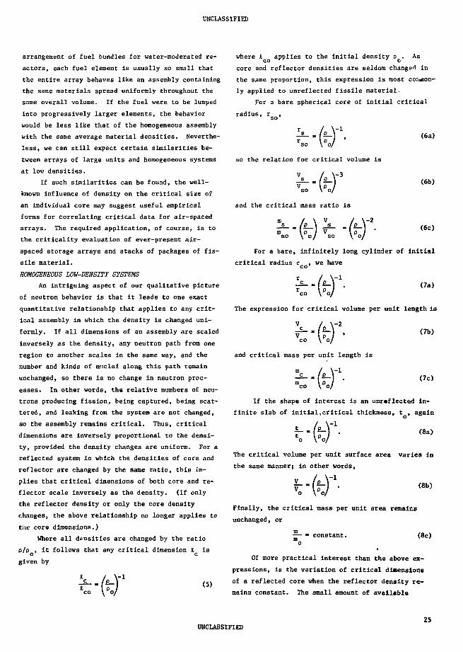
UNCLASSIFIED
arrangement of fuel bundles for water-moderated re-
actors, each fuel element Is usually so small that
the entire array behaves like an assembly containing
the same materials spread uniformly throughout the
same overall volume. If the fuel were to be lumped
into progressively larger elements, the behavior
would be less like that of the homogeneous assembly
with the same average material densities. Neverthe-
less, we can still expect certain similarities be-
tween arrays of large units and homogeneous systems
at low densities.
If such similarities can be found, the well-
known influence of density on the critical size of
an individual core may suggest useful empirical
forms for correlating critical data for air-spaced
arrays. The required application, of course, is to
the criticality evaluation of ever-present air-
spaced storage arrays and stacks of packages of fis-
sile material.
HOMOGENEOUS LOW-DENSITY SYSTEMS
An intriguing aspect of our qualitative picture
of neutron behavior is that it leads to one exact
quantitative relationship that applies to any crit-
ical assembly in which the density is changed uni-
formly. If all dimensions of an assembly are scaled
inversely as the density, any neutron path from one
region to another scales in the same way, and the
number and kinds of nuclei along this path remain
unchanged, so there is no change in neutron proc-
esses. In other words, the relative numbers of neu-
trons producing fission, being captured, being scat-
tered, and leaking from the system are not changed,
so the assembly remains critical. Thus, critical
dimensions are inversely proportional to the densi-
ty, provided the density changes are uniform. For a
reflected system in which the densities of core and
reflector are changed by the same ratio, this Im-
plies that critical dimensions of both core and re-
flector scale inversely as the density. (If only
the reflector density or only the core density
changes, the above relationship no longer applies to
the core dimensions.)
Where all densities are changed by the ratio
p/p , it follows that any critical dimension Jl is
given by
(S)
where I applies to the Initial density pQ. As
core and reflector densities are seldom change"! in
the same proportion, this expression is most cor^aon-
ly applied to unreflected fissile material.
For a bare spherical core of initial critical
radius, rsQ,
(6a)
(6b)
(6c)
so the relation for critical volume is
\-3
-2
and the critical mass ratio is
m / \ V / \
m Ip / V Ip /so \ o/ so \ o/
For a bare, infinitely long cylinder of initial
critical radius r , we have
and critical mass per unit length is
/
(7a)
The expression for critical volume per unit length is
(7b)
(7c)
If the shape of interest is an unreflected in-
finite slab of initial,critical thickness, t , again
(8a)
The critical volume per unit surface area varies in
the same manner; in other words,
(8b)
Finally, the critical mass per unit area remains
unchanged, or
m— • constant. (8c)
Of more practical interest than the above ex-
pressions, is the variation of critical dimensions
of a reflected core when the reflector density re-
mains constant. The small amount of available
UNCLASSIFIED25

experimental Information about density changes In
near-homrfeneoua cores la preaented In TID-7028, p.4
and Fig' 6. Reaulta are cooslatent with a relation-
ship like Eq. (6c) for critical masses of spheres
(or cubes, or near-equllat«ral cylinders), so
(9)
10'
where a la approximately constant over the range
0.5 s p/p $ 1. (The exponent a cannot exceed the
value 2 that applies to a bare sphere.) Actually, a
for a core with conatanc-desslt; reflector must in-
crease with decreasing density. As core density
approaches zero, core size approaches Infinity and
a must approach 2, because the distinction between
infinite bare and reflected corea la meaningless.
Figure 15 gives (DTK) calculated values of the
core-density exponent a for a variety of water-
reflected spherea, which apply to the density range
between normal and 0.8 normal. The value a • 1.5 la
typical of small corea, but a generally Increases
with core size and approaches 2 as the core volume
becomes very large.22
Computations (DTK) that extend to very email
values of P/P O > Figs. 16 and 17, show the increase
of the core-density exponent of a water-reflected
aphere with decreasing density. The exponent be-
comes essentially 2 when p/p < 10'o
,-3 At theae very
low densities, all curves are parallel and there is
a constant ratio of critical masses of bare and
10=
10
10"
10
— V- W -
s ^>>
• 1 =13 \
y \
m \\
\
Pr
\
f
<
\
\
:omput»d DTK
V
1- s •
\
V\
\
'< \
\
-\\r\\\
»ti.
Ussri
rh-
* :
KJJ
i
10" 10-t 10-"
Fig. 16. Computed critical masses of spheres withcore densities reduced by the fractionp/p0; water-rcflectad U(93) attal, 0(93)0,,or U(93)F,, and unreflectad 0(93) —"-*
''4O.I * * * 1.0 ' * • 10 ' * • 100 7 * °IOOO
H/"'\J Of H/"'Pu otomic rotio
Fig. 15. Computed Initial core-density exponentsfor water-reflected spheres of mixtures ofwater with 239Pu, 0(93.5), 0(30), 0(5), orO(93.S)-graphltc at C/235U - 157. Criticalsices are Infinite where s « 2.
corresponding reflected spheres. Values of this nmx-
iaum ratio, R, for the various core compositions of
Figs. 16 and 17, arc shown la Table V.2*
TABU V
LIMITING RATIOS OF CRITICAL MASSES OF BAKE A WWATER-REFLECTED SPHEXES AT LOW DERSITT
Cora Composition ma(bar.)/ma(refl)
0(93) metal 13
O(93)02 8.0
O(93)F6 6.0
D(93)CM 2.7
U(93) solution, B/USri - 60 5.4
0(93) solution, B/233O - 400 2.7
Pu oetal 19
26

10'
2 10*
• 0
I
—
-
g
1—
— <»
1i
pco
I
!
1
U/liter._i_b
20 g
i
mpul
-pr1 ,
O f •
j I
iiU/liter
A
\
•• r«fl.«=
ad OT
II
i
v
ttH!|70g U/lifsr, bore
r!
IIDgU/lil
ert
::- -L
A:
\
|—i
r—
\
re
V
• I I I
Mr:::
s
\ V
\ *
iI
|
10" 10''
Fig. 17. Computed relative critical masses ofspheres with core densities reduced by thefraction p/po; water-reflected and unre-flected U(93) solutions at 70 or 420 g U/liter (H/235U - 400 or 60).
As indicated before, the core-density exponents
for homogeneous systems may be applied to certain
materials that are actually heterogeneous, such as
oxide pellets, machine turnings, and dry lattices of
fuel rods for water-moderated reactors. Heterogene-
ity will be unimportant if each piece is so small
that a neutron originating in it has little chance
of producing another fission before leaving the
piece. For many materials and shapes, this require-
ment will be satisfied If one dimension of the piece
does not exceed approximately 1/2 In.
NEAR-EQUILATERAL AIR-SPACED ARRAYS
We can expect the critical mass of a low-density
system to decrease ae the fissile material is lumped
into larger units while the same overall density is
maintained. In other words, the critical mass of a
three-dinensional air-spaced array is smaller than
that of a similar homogeneous system of the same ma-
terial at the same average density. As more materi-
al is lumped into units, there is increased chance
that a fission within one unit will lead directly to
other fissions within the same unit, and the fission-
chain efficiency of the entire array also Increases.
In the limit, the most efficient "array" (that of
smallest critical mass) consists of one critical unit
at full density.
To illustrate how the critical content of arrays
depends upon unit size and the spacing between units
(overall density), we turn to precise experimental
information about arrays which appears in Part II of
TID-7028. Each of the critical air-spaced arrays
to be considered has the same number of U(93) metal
or solution cylinders along each of the three prin-
cipal axes. In other words, each array contains 8,
27, 64, ... units. Cylinders are compact in that
their heights do not differ greatly from their diam-
eters, and the surface-to-surface spacing between
cylinders is uniform. Reflected arrays are surround-
ed by 1- to 6-in.-thick paraffin spaced from the out-
er units by one-half the surface-to-surface spacing
within the lattice. A metal array, as set up at
ORNL, Is shown in Fig. 18.
Data for critical arrays of U(93) metal cylin-
ders are shown in Fig. 19, and Fig. 20 gives similar
data for cylinders of solution in 1/4-in.-thick
Plexiglas containers. The abscissa p/p is the frac-
tion of the lattice volume occupied by 0(93) aetal
or solution (the lattice volume per unit). The re-
flected arrays sc represented are surrounded by 6-
in.-thick paraffin.
For criticality safety guidance, the unreflected
arrays are of only academic interest because practi-
cal storage arrangements always involve some reflec-
tion, often by concrete walls. Although concrete is
An equivalent statement is that the "neutron multi-plication" of the piece should be little greaterthan unity.
All of the suitable criticality data for arrays inTID-7028 originated at ORNL. Other informationabout subcritical arrays can be valuable for evalu-ating the safety of similar systems, but it is notappropriate for developing a general model.
27
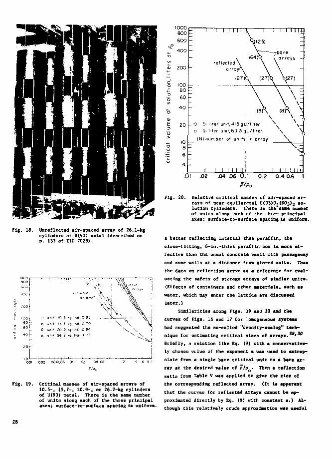
Fig. 18. Unreflected air-spaced array of 26.1-Jcgcylinders of U(93) metal (described onp. 133 of TID-7028).
1000800
_1 0 0
80
6 0
4 0
D
««•'
u m f
unit
„ , , ,
10
15
JO
26
5
7
9
2
"1,
•").
kg
rvd--
nrt •
M l "
0 950 700 94
1 17
001 002 004 006 01 Od 34 06
Fig. 19. Critical masses of air-spaced arrays of10.5-, 15.7-, 20.9-, or 26.2-kg cylindersof U(93) metal. There is the same numberof units along each of the three principalaxes; surface-to-surface spacing is uniform.
1000800
600
4C0 -
Q> 200 -
co
CD
£
oo
10080
60
40 -
20 -
1086
4 -
- 1
-
-
Mi
ll
1
_ O 5-D 5-
1 1 1 M M ]
r e f l e c t e d ^
iter un t,
iter unit,
(N) number o
1 1
1
1
1 1
1
1 1 1
(27^
. 1 1
S(125)
(64)h \
\4l5gU/hter N
63.3gU/hter
units
I
Mill
in arroy
1 1
1 1 1 1
Tbarearrays
0(27)
V\\1 1 ! |
14-
-
< i
i i
11
.01 .02 .04 .06 0.1 0.2 0.4 0.6 1
Fig. 20.Relative critical masses of air-spaced ar-rays of near-equilateral U(93)02(NO3)2 so-lution cylinders. There is the sane numberof units along each of the chtes pilnclpalaxes; surface-to-surface spacing is uniform.
a better reflecting material than paraffin, the
close-fitting, 6-ln.-thick paraffin box is aore ef-
fective than tht usual concrete vault with passageway
and some walls at a distance froa stored units. Thus
the data on reflection serve as a reference for eval-
uating Che safety of storage arrays of slcilar units.
(Effects of containers and other materials, such as
water, which may enter the lattice are discussed
later.)
Similarities among Figs. 19 and 20 and the
curves of Figs. 16 and 17 for .oinogeneous systems
had suggested the so-called "density-analog" tech-
nique for estimating critical sizes of array*. "*"
Briefly, a relation like Eq. (9) with a conservative-
ly chosen vtlue of the exponent s was used to extrap-
olate froc a single bare critical unit to a bare ar-
ray at the desired value of P/PQ- Then a reflection
ratio from Table V was applied tc give the size of
the corresponding reflected array. (It Is apparent
that the curves for reflected arrays cannot be ap-
proximated directly by Eq. (9) with constant s.) Al-
though this relatively crude approximation was useful
28
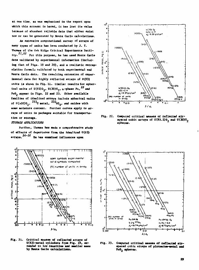
at one tine, as was emphasized in the report upon
which this account is based, it has lost Its value
because of abundant reliable duta that either exist
now or can be generated by Monte Carlo calculations.
An extensive conp'jtational survey of arrays of
many types of units has been conducted by J. T.
Thosas of the Oak aidge Critical Experlaencs Facil-
ity.'""' Fer this purpose, he has used Monte Carlo
data validated by experimental information (Includ-
ing that of Figs. 19 and 20), and a realistic extrap-
olation formula validated by both experimental and
Monte Carlo data. The resulting extension of exper-
imental data for highly reflected arrays of U(93)
units Is shown in Fig. 21. Similar results for spher-
ical units of U(93)02, 0(30)02, o-phase Pu.33and
PuO2 appear In Figs. 22 and 23. Other available
families of Idealized arrays include spherical units
of O(>30)02, 2 3 3U metal, 2 3 3U0 2 > and oxides with
some moisture content. Further curves apply to ar-
rays of units In packages suitable for transporta-
tion or storage.
STORAGE APPIICATJOKS
Further, Thomas has made a comprehensive study
of effects of departures from the idealized 0(93)
arrays. Be has examined Influences upon
(I0001Q
(N)-numbtr of tint'sin orray
Fig. 22. Computed critical masses of reflected air-spaced cubic arrays of 11(93.2)0, and 11(30)0,sphere*.
S *
i i i i n n
open symbols experimentolso'id symbols computed
(N) number of units in orroy
I I I I I i I:
I TO1 I I I I I III ; I i i i 11 i i \ I I I I I i i2 « 6 8 O I 2 4 6 8 I 2 « 6 8 i
8 i o
P'Po
rig. 21. Critical masses of reflected array* ofU(93)-metal cylinders from Fig. 19, ex-tended to low densities and smaller massby Mont* Carle calculations.
Fig. 23. Computed critical masses of reflected alr-apaccd cubic arrays of Plutonium metal andPuOj spheres.
29

critical-array size of unit-shape changes and densi-
ty changes, of intermingling different units, and of
interposing materials such as steel, plastic, or wa-
ter within the lattice. This information is a good
guide for translating from the idealized arrays to
practical storage configurations.
For example, let us consider the vault storage
of as many as two hundred 10.5-kg hemispherical
shells of U(93), each in a closed, 1/8-in.-thick-
wall steel can on sturdy steel shelving. A safe
spacing between such units might be judged as follows
by reference to the curve for 10.5-kg cylinders in
Fig. 21. This curve says that 2100 kg of the cylin-
ders (the 200 units) would be critical at the aver-
age lattice density p/o » 0.025. The same number
of shells at this lattice density would be subcrit-
ical because a neutron within a shell is more likely
to escape the shell without producing more neutrons
by fission than is a neutron in the near-equilateral
cylinder. Let us say (as is probable) that Thomas'
guidance indicates that part, but not all, of this
effect is compensated by the presence of steel cans
and shelving. (Further, Thomas shows that the steel
cans prevent critical-mass reduction by water flood-
ing.) Although it appears that the storage arrange-
ment would be subcritical at the 0.025 lattice den-
sity, let us reduce critical mass by the seemingly
liberal safety factor of 10. This leads to the
21,000-kg iioint on the curve of Fig. 21, which cor-
responds Co D/P « 0.0074, the fraction of the lat-
tice occupied by U(93). The 10.5 kg of metal has a
volume of 34 in. , so the space to be allowed per
shell is 34/U.0074 « 4600 in.J or a 16.6-in. cube.
Note that the safety factor of 10 was equivalent to
increasing the center-to-center spacing of units
from 11.1 to 16.6 in. If one wished to round off
the spacing to 16 in., a usually adequate safety
factor cf greater than 8 would be retained. It is
apparent that other i 10.5-kg metal units, such as
cans of dry metal turnings or clusters of small
pieces, could safely replace shells in the storage
configuration.
Of course, the convenient matching of masses in
this illustration is not essential. If, for example,
we had considered 14-kg shells, either the reference
curve for 15.7-kg cylinders could have been used di-
rectly, or another could have been obtained by inter-
polation between the curves for 10.5- and 15.7-kg
units. When appropriate families of reference data
are not available, it may be desirable to use Monte
Carlo techniques, such as KENO, explicitly for the
realistic analysis of proposed storage arrays.
The solution arrays of Fig. 20 do not apply di-
rectly to most large storage arrangements because
the near-equilateral containers are less practical
than long cylinders of larger volume. Specific guid-
ance, however, is available in the form of many ex-
perimental critical patterns of 11(93) solution in
tubular containers described in Part II of TID-7028.
Similar results for U(4.9)0_F. solution have been37
reported subsequently.
One extensive series of experiments established
critical arrays of UOSXJjCNO,^ solution in a com-
mon type of polyethylene storage container. Each
-0.35-in.-wall, 4.7-in.-diam, 44-in.-high vessel
contained 12-3/4 liters of solution. From the many
essentially unreflected arrays of these cylinders,
three with equilateral outline can be represented on
a plot like Fig. 20. One is a two-high arrangement
like that shown in Fig. 24. The other two are one-
high with square and hexagonal patterns. Figure 25
Fig. 24. Double-tier array of 13-liter polyethylenecylinders containing U(92.6)0,(NO.)2 solu-tion (described on pp. B0 and 111 ofTID-7028.)
30
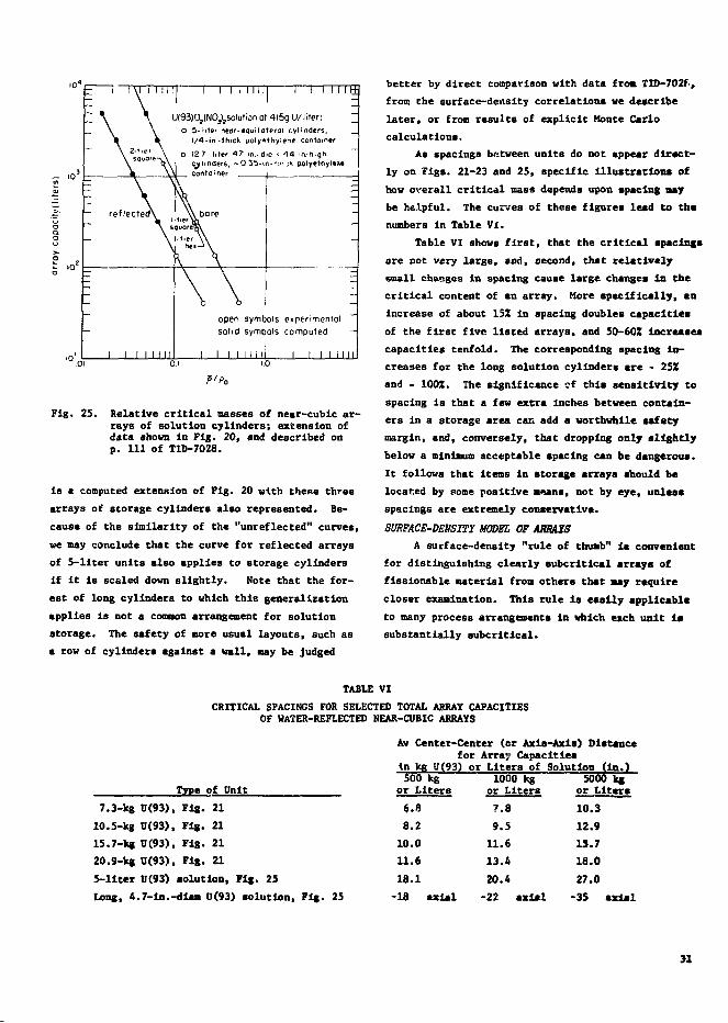
10"
\ 2-tie>
reflected
-
Ill 1 1 1 1
1
I I I I
1 ! 1 1
I
\
A
1 1II
I 1 1 M i l 1 1 1 1 1 1 r+
JOSJO^NO^Solution at 4l5g U/lrter: "o 5-Mer neor-equiiaterai cylinders, _.
1/4-in -thick polyethylene container
D 12 7-liter 47-m.-tJio * 44-ia-highcylinders, - 0 35-in-m- A polyethylene
, container
k\bare
OuoreBV
\ \
opensolid
1 1 1 1
symbsymb
urn
-
-
ols experimental ~
ols computed —
N i l ! 1 1 1 1 1 1 I IO.i
P'P0
Fig. 25. Relative critical masses of near-cubic ar-rays of solution cylinders; extension ofdata shown in Fig. 20, and described onp. Ill of TID-7028.
is a computed extension of Fig. 20 with these three
arrays of storage cylinders also represented. Be-
cause of the similarity of the "unreflected" curves,
we may conclude that the curve for reflected arrays
of S-llter units also applies to storage cylinders
If it is scaled down slightly. Note that the for-
est of long cylinders to which this generalization
applies is not a common arrangement for solution
storage. The safety of more usual layouts, such as
a row of cylinders against a wall, may be Judged
better by direct comparison with data froa TID-702f,
from the surface-density correlations we describe
later, or from results of explicit Monte Carlo
calculations.
As spacings between units do not appear direct-
ly on Figs. 21-23 and 25, specific Illustrations of
how overall critical mass depends upon spacing say
be helpful. The curves of these figures lead to the
numbers in Table VI.
Table VI shows first, that the critical spacing*
are not very large, and, second, that relatively
small changes in spacing cause large changes In the
critical content of an array. More specifically, an
increase of about 15Z in spacing doubles capacities
of the first five listed arrays, and 50-60Z Increases
capacities tenfold. The corresponding spacing In-
creases for the long solution cylinders are - 25Z
and - 100Z. The significance of this sensitivity to
spacing is that a few extra Inches between contain-
ers in a storage area can add a worthwhile safety
margin, and, conversely, that dropping only slightly
below a minimum acceptable spacing can be dangerous.
It follows that items in storage arrays should be
located by some positive Beans, not by eye, unless
spacings are extremely conservative.
SURFACE-DENSITY MODEL OF ARRAYS
A surface-density "rule of thumb" is convenient
for distinguishing clearly subcrltical arrays of
fissionable material from others that may require
closer examination. This rule Is easily applicable
to many process arrangements In which each unit i»
substantially aubcritical.
TABLE VI
CRITICAL SPACINGS FOR SELECTED TOTAL ARRAY CAPACITIESOF WATER-REFLECTED NEAR-CUBIC ARRAYS
Av Center-Center (or Axis-Axis) Distancefor Array Capacities
In leg U(93) or Liters of Solution (In.)
Type of Unit
7.3-kg U(93), Fig. 21
10.5-kg U(93), Fig. 21
15.7-kg U(93), Fig. 21
20.9-kg 0(93), Fig. 21
5-liter U(93) solution, Fig. 25
Long, 4.7-ln.-dlam U(93) solution, Fig. 25
500 kgor Liters
6.8
8.2
10.011.618.118 axial
1000 kgor Liters
7.8
9.5
11.613.420.4
-22 axial
5000 kgor Liters10.312.915.718.027.0
-35 axial

TABLE VII
REFERENCE SURFACE DENSITIES FOR SELECTED FISSILE MATERIALS
Conpositiop
U(93) solution
U(93) GOlution,s 50 g U/t
D(5) solution
Stable PufliO ),solution J
233U solutionU(93) metal
ll(93)F, + 0.1HFb
a-phase Puj-phase Pu,
Maximum Unit Site5.0-in.-o.d. cylinder5.5-ln.-o.d. cylindert.O-in.-o.d. cylinder6.5-in.-o.d. cylinder
8.0-ln.-c.d. cylinder4.7-ln.-o.d. cylinder
4.5-ln.-o.d. cylinder15 kg U*27 kg U*50 kg Ua
50 kg U*3 kg Pu1
4.5 kg Pu or U a
Reference Surface Density
1.6 on/cm2 (1.5 I/ft2)
1.2 int/cm2 (1.1 t/ft2)
3.6 m£/cm2 (3.4 I/ft2)
9.6 ml/on (9.0 i/it )
1.4 ml/cm2 (1.3 e/ft2)
13 g/cm2 (12 kg/ft2)
12-5 g/cm2 (11.5 kg/ft2)
11.5 g/cm2 (10.5 kg/ft2)
7.5 g/cm2 (7 kg/ft2)
5.5 g/cm2 (5.2 kg/fc2)
5.5 g/cm2 (5.2 kg/ft2)
Reduced 5Z for container effects.
The simplest situation is a uniform array of
fissionable units. Then if the surface density of
fissionable material, as projected onto the largest
bounding plane of the array (usually floor or wall),
does not exceed a reference value for that material,
no more detailed evaluation is necessary. Reference
surface-density values and corresponding unit-size
limits for selected materials are listed in Table
VII. As an illustration, consider 12-kg units of
highly enriched uranium metal, arranged on the floor
of a storage area in a square array with 15-in. cen-
ter-to-center spacing. Table VII quickly shows that
this configuration Is acceptably subcritical, be-
cause the 12-kg unit is less than thfi 15-kg limit2
for U(93) metal, and the surface density, 12(12/15)2
» 7.7 kg/ft , is about twc-thirds the reference
value. Other simple situations to which the table
applies would Include a square array of vertical
solution cylinders with surface density as projected
onto the floor, or a line of storage cylinders along
a wall with surface density as projected onto that
wall.
The rule can be extended directly to nonunifovm
plant layouts in which surface densities for the
various materials are separable (e.g. where, in a
basically horizontal layout, different materials are
not stacked in the same column). In such a case,
the most intensive concentration of each material
should be examined in terms of the values in Table
VII. vis we shall see, some "nonseparable" cases
can also be handled.) Although practical arrangements
seldom exceed the reference values, it should be em-
phasized that a larger surface density does not ne-
cessarily indicate an unsafe condition. Instead, it
would call for a more detailed evaluation. . It is
apparent that the listed values of both surface den-
sity and unit size, which apply to infinite arrays,
may be relaxed for finite systems. The extent of
such relaxation, however, is a complication that we
will not pursue.
To gather some insight, we should consider the
way in which the surface-density rule Is based on
the properties of critical planar arrays of identi-
cal units, e.g. a square horizontal pattern, one
unit high. As the array size is increased by adding
units horizontally, the critical spacing increases,
Implying a decrease in critical surface density. Ul-
timately values of spacing and density are attained
such that the critical size Is infinite. For our
purpose, we assume that the relationship between
critical surface densities of the infinite array and
those of a reflected infinite slab of the sane fis-
sionable material depends simply upon the size of
unit in an array.
The infinite uniform slab is introduced because
its critical thickness is easily computed and can be
related to critical surface densities of a large
family of arrays. For example, a water-reflected
infinite slab of U(93) metal would have a critical
thickness of 0.68 in., so it could be viewed as made
up of 0.68-in. cubes in contact. Larger cubes would
have to be spaced for criticality, and the surface
density would decrease below the slab value of 32 g/2 2
cm (or 30 kg/ft ). Results of Monte Carlo calcula-
tions indicate that this decrease will not exceed
60% if the mass of a unit is limited to about 0.3
of a critical unreflected mass of similar shape.
The guiding Monte Carlo data are illustrated by
the lower curves of Fig. 26. One of these curves,
provided by J. T. Thomas, gives the ratio of surface
density of a reflected 11(93) metal array to that of
Note that an infinite planar system would necessar-ily be well-reflected, because, unlike a finiteform, it is as good a target for neutrons returnedfrom distant objects as from nearer ones.
The 50% decrease suggested in the report that pre-ceded this account has been adjusted for consist-ency with the data by Stevenson and Odegaardenwhich will be cited.
32

3.O
2.5
r 20o
1.0 t
0.5
to Infinity
reflected 10-unit cubic arrays(NB* method)
a equilateral cylinders of U(93) metal• cubes of U(93) metal
X 20-in.-hiqh cylinders of U(93) solution
reflected 10-onit planar arrays(Monte Colo)
•olutioo
L lol ldl large UI93)solution cylinder!
O.I 0.2 0.3 0.4 0.5
(moss of unit)/(similar bare critical moss)
0.6 O.T
Fig. 26. Critical surface densities of air-spaced arrays relative to surfacedensities of critical reflected infinite slabs. Note that valuesfor cubic arrays are much greater than those for planar arrays.
the reflected slab as a function of unit size.
The similar curve for 11(93)0^2 solutions at the a-
tomic ratio H/235U « 44 is adapted from data by
Stevenson and Odegaarden. Reference values and
unit limits from Table VII are represented by the
horizontal line for solids, by the dotted extension
to the abscJ- a 0.33 for the basic solution cylin-
ders, and I the further dotted extension for the
two larger cylinders of U(93) solution of unlimited
concentration.
Although we have associated the surface-density
concept with planar arrays, the values deduced are
still more conservative when applied to three-dimen-
sional arrays (which are necessarily finite). This
is illustrated by the upper curve of Fig. 26, which
refers to critical reflected arrays of one-million
11(93) metal cylinders as established by Thomas' re-
liable extrapolation scheme. For "0.3-critical"
units, the critical surface density is seen to exceed
the reference value from Table VII by a factor of 4.
Similarly, this factor of conservatism ranges from
>2 to >6 for the critical arrays listed in Table VI.
(Values increase from the lower right-hand to the
upper left-hand entries.) Moreover, in many practi-
cal layouts, this large margin of safety is found to
be inherent.
Unlike that of a planar array, which may be
characterized by an individual cell, the surface den-
sity to be considered for a cubic array is the total
mass of a column of units divided by the base area
of a cell. This difference implies that the two
types of arrays containing mixed units cannot, in
general, be handled similarly. Although the various
cells of a mixed planar array can be evaluated inde-
pendently, the treatment of a three-dimensional array
in which units are mixed within columns and rows is
not so straightforward. In such a case, one can
sometimes use information about equivalent units of
33
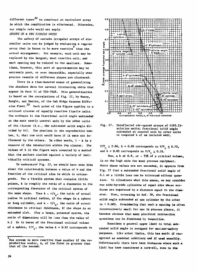
different types to construct an equivalent array
in which the complication is eliminated. Otherwise,
our simple rule would not apply.
GROUPS OF A FEW FISSILE UNITS
The safety of certain irregular arrays of dis-
similar units can be judged by evaluating a regular
array that is known to be more reactive than the
actual arrangement. For example, each unit may be
replaced by the largest, most reactive unit, and
each spacing may be reduced to the smallest. Some-
times, however, this sort of approximation may be
extremely poor, or even Impossible, especially when
process vessels of different shapes are clustered.
There is a time-honored means of generalizing
the abundant data for several interacting units that
appear in Part II of TID-7028. This generalization
is based on the correlations of Fig. 27, by Henry,
Knight, and Newlon, of the Oak Ridge Gaseous Diffu-
sion Plant.1 Each point of the figure applies to a
critical cluster of equally reactive fissile units.
The ordinate is the fractional solid angle subtended
at the most nearly central unit by the other units
of the cluster (i.e., the subtended solid angle di-
vided by 4n). The abscissa is the reproduction num-
ber, k, that one unit would have if it were not in-
fluenced by the others. In other words, 1 - k is a
measure of the interaction within the cluster. The
values of k in the figure were computed by a method
that the authors checked against a variety of indi-
vidually critical systems.
To understand Fig. 27, we should have some idea
about the relationship between a value of k and the
fraction of the critical size to which it corres-
ponds. For a fissile system that contains little
poison, k is roughly the ratio of a dimension to the
corresponding dimension of the critical system of
the same shape. Thus k . r/r , the ratio of actual
radius to critical radius, if the shape is a sphere
or long cylinder, and k - t/tc> the ratio of actual
thickness to critical thickness, if the shape is an
extended slab. (For a large, poisoned system, the
ratio of dimensions will be less than the value of
k.) So in terras of the fractional critical volume
of a sphere, V/Vc, the value k - 0.95 corresponds to
C O
•9
8
—I o 3O0.5
O. 1
0.:
- - :ylinde
1
•
\1C
- infinite ten- 6" cylinder
X »p
Ofi
VI
h
gl-h
3-8"c
r1
\
ylinder1 1 1
E
1 1 1 1Ml
lit arrayT
2-IC
_1
)"c
• be
,-3-3"slabc
1
- ^
Q
. _
3" cylDl
\
>7
\
srsnd
s
sr
3's
r
3.9
1
r
0 j
\
1
6
,intmit8" cyl
e
-
0
ndc
rii
rth
I5"cylindart
a:itfc
One system is more reactive than another if the re-production number, k, of the first is greater thanChat of the second.
multipljcotion factor, k, of individual container
Fig. 27. Unreflected air-spaced arrays of U(93.2)-solution units; fractional solid anglesubtended at central unit by other unitsvs computed k of an isolated unit.
V/Vc < 0.86, k = 0.90 corresponds to V/Vc < 0.73,
and k « 0.80 corresponds to V/V £ 0.51.
Now, a k of 0.9, or - 7531 of a critical volume,
is on the high side for most process equipment.
Where these values are not exceeded, It appears fron
Fig. 27 that a subtended fractional solid angle of
0.1 or a little less can be tolerated without ques-
tion. To illustrate what this means, we may consider
two side-by-side cylinders of equal size whose sur-
faces are separated by a distance equal to the dim-
eter. Then, according to Ref. 39, the fractional
solid angle subtended at one cylinder by the other
is < 0.085. Considering that such a spacing Is often
inconveniently small for use in process plants, it
becomes obvious that many practical interaction
questions can be dismissed by inspection.
Sometimes a general upper limit to total sub-
tended solid angle is assigned for nuclear-safety
purposes. Like other limits, this has merit If rec-
ognized as somewhat arbitrary and if used sensibly.
Unfortunately there have been instances where such a
limit has been considered a cure-all, even to th«
point of substituting it for direct comparison with
experiment. This comment, of course, is no reflec-
tion on the method, and applies equally to any form-
alism that is used without discrimination.
An illustration of the need for discrimination
is suggested by the critical combination of solution
annulus and solution cylinder shown in Fig. 7. If
the diameter of the axial cylinder is about 5 in.
and the inside diameter of the annulus is, say, 20
in., the combination will be safely subcritical even
though the annulus surrounds the cylinder complete-
ly. A solid-angle limit, of course, would reject
this configuration.
As we have implied, safety evaluation by means
of solid angle is most appropriate where several
large process vessels are crowded together. This is
just the situation where it is pointless to attempt
a precisicn calculation of solid angle, because in-
teraction at small spacings is not a simple geomet-
ric concept. A judicious estimate of solid angle
will do all that can be justified.
He should mention that several techniques for
approximating large critical arrays make use of sub-
tended solid angles. These include the interaction40
parameter method of Thomas and Scriven, the inter-41
action potential methods of Newlon, and an albedo42
(neutron reflection) scheme by Clark. Each of
these methods is used with success, and the inter-
ested reader is referred to accounts by the authors.
FURTHER OBSERVATIONS ABOUT INTERACTION
Several more questions about interacting fis-
sile units arise commonly during nuclear safety a-
nalyses. These questions and datj that help to an-
swer them will be considered now.
1. What arrangement of neighboiing fissile
units has the same effect us complete water reflec-
tion? For an 8-in.-diam cylinder of U(93)0,F, solu-
tion at 538 g of U/liter, Fig. 63 of TID-7028
gives the water-reflected critical height as 9.25 in.
(the point at the extreme right). Figure 64 (TID-
7028) applies to the same cylinder in unreflected
air-spaced clusters. He see that £ triangular clus-
ter of three of these cylinders in contact has a
slightly larger common critical height than the sin-
gle water-reflected cylinder, and that a hexagonal
cluster of seven of the cylinders spaced - 1.5 in.
apart has the same critical height as the reflected
cylinder. In other words, two extra similar
cylinders in contact, or six extra cylinders separa-
ted by 1.5 in., have about the same effect as water
reflection.
2. Another question, about the effectiveness
of cadmium (a neutron poison) between interacting
cylinders, is partially answered by these same fig-
ures. Figure 63 shows that cadmium on container
surfaces increases the critical height of water-
flooded clusters of the cylinders, provided the sur-
faces are separated by several inches. Then both
the effect of water as a reflector and of interaction
between cylinders decreases. The unreflected air-
spaced clusters (Fig. 64), however, are influenced
very little by the presence of cadmium. This is con-
sistent with the fact that high-energy neutrons,
which would not be captured by cadmium, are respon-
sible for most of the interaction among air-spaced
units.
3. What is the influence of a nearby concrete
wall on the critical size of an otherwise unreflected
array of fissile units? The answer, for arrays of
6-in.-diam by 50-in.-high cylinders of U(93}0,(NO,),
solution at 384 g of U/liter, is given by Fig. 74
of TID-7028. With spacings of 4.9 in. (12.3 cm) be-
tween container surfaces, the critical number of
units in an array against an 8-in.-thick concrete
wall is 9.2, as compared with 15.1 units in an array
without reflection. Note that an 8-in.-thick slab
of water and Flexiglas against the array is slightly
less effective than the concrete, the critical num-
ber being 9.5 units at the same spacing. Roughly,
then, the effect of either wall is to reduce the
critical number by 403!. This influence should scale
as do effects of a complete reflector about arrays
of different materials (see Table V), so the frac-
tional reduction would be greater for U(93) metal
and less for dilute U(93) solution.
As the result of Monte Carlo calculations,43
Thomas and Crume conclude that 5- Co 6-in.-thick
concrete surrounding an array is essentially equiva-
lent to a thick water reflector. Unlike water, the
concrete reflector becomes more effective as thick-
ness is increased even beyond 10 in.
4. At least a clue about the next question,
"How far apart must arrays be spuced so that their
influence on each other may be neglected?," is also
contained in Fig. 74 of TID-7028. The most appropri-
ate experiment that helps answer this question is
35

represented by the split array at the upper left of
the figure. As it seems plausible that two arrays
interact much like a pair of individual units, it is
appropriate to ask whether halves of the split array
follow the general correlation between solid angle
and k that appears in our Fig, 27. Formally, at
least, the fraction of solid angle subtended by one-
half of the array at the center of the other half is
0.26, and the value of k for each half if isolated44 *
from the other is estimated to be 0.85. This
point happens to fall on one of the curves of Fig. 27
and so encourages us to use a solid-angle limit for
judging interaction between arrays. The generally
tolerable value that was discussed for individual
units is a fractional subtended solid angle of -0.1.
Using this same limit, we arrive at the rule of thumb
that the interaction between two arrays can be tol-
erated if they are separated by the largest dimen-
sion of either array. (We recall, for example, that
two equal cylinders separated by one diameter fall
within the suggested solid-angle limit.) Of course,
any generally accepted interaction limit depends up-
on the safety factor allowed for each array. We as-
sume safety margins similar to those discussed in
the next section.
5. Now that we have some idea of the reduction
of interaction by spacing, we ask: "What is the in-
fluence of intervening walls of various materials?."
Again, Fig. 74 of TID-7028 has a partial answer for
an 8-in.-thick wall of concrete, or of water and
Plexiglas. We noted the array of 9.2 cylinders that
was critical when simply against a concrete wall.
Without change of spacing, four extra cylinders
against the far side of the concrete reduce the orig-
inal critical number to 8.9, and a dual array of 8.0
cylinders on each side of the concrete is just crit-
ical. As will be seen in the next section, this 132
overall effect of interaction through the concrete
is a email fraction of any reasonable safety factor.
At a smaller spacing, a critical array of 8.50 units
The subtended .solid angle is obtained by the methodof TID-7016, p. 35, where similar cells abouteach unit define the boundary of each half-array.The critical number of units in a single array (atthe spacing of the split array) is Nc • 13.0 by in-terpolation of data from Figs. 61 and 74 of TID-7028.The value of k in each half of the split array, con-taining N • 8 units, is about the ratio of averagedimension to critical dimension, so that k - (H/H )l/3 . 0.85.
against a water-Plexiglas wall becomes 8.48 with
four units against the opposite side, and 8.00 with
the same number of units opposite. Note that the
interaction as measured by balanced critical arrays
is more extreme than would be encountered under plant
conditions; the interaction with a one-half critical
array on one side (four units in this case) repre-
sents a more realistic upper limit if the normal
safety factors of the next section are considered.
Again, Thomas has supplemented these observa-
tions by means of Monte Carlo. His results lead
to the conclusion that 4- to 10-in.-thick concrete
walls are much more transparent than similar thick-
nesses of water.
To the extent that arrays and slabs of fissile
material interact similarly, recent measurements by•jo
McCreless, Smith, Jarvis, and Duffey contribute to
the answer of the last question. They measured In-
teraction through each of several materials in terms
of change of critical height of a 21-in.-diam U(93)
metal disk against one side of the material when a
similar disk of one-half critical height was placed
against the other side. Results for 8-in. thickness-
es of all materials investigated and for smaller
thicknesses of polyethylene are summarized in Table
VIII. One of the more surprising results is the
isolating effect of lead, which does not capture
neutrons readily. Apparently, scattering tends to
TABLE VIII
INTERACTIONS OF TWO 21-IN.-DIAM DISKS OF U(93) METALON OPPOSITE SIDES OF SLABS OF VARIOUS MATERIALS'1
Intervening Single-Disk Interaction asMaterial Critical Change of
Thickness (In.) Height (in.) Critical Height (inj
Air
Concrete
Plywood
Beryllium
Lead
Polyethylene
Polyethylene
Polyethylene
Polyethylene
Air
8
8
8
8
8
8
6
4
2
2
2.81
2.00
2.24
1.60
2.22
2.16
2.16
2.17
2.21
2.81
0.175
0.04
0.06
0.03
0.02
not detectable
not detectable
0.05
0.40
0.67
One disk, is equivalent to one-half the isolatedcritical disk. Interaction is measured as the In-fluence of the half-critical disk on the criticalheight of the other disk.
36

return neutrons to the plate in which they originate,
and elements of high atomic weight, such as lead,
are particularly effective back-scatterers. The re-
sults for concrete and polyethylene are roughly con-
sistent with the array measurements of TID-7028 dis-
cussed above.
6. The effect of water or other hydrogenous
material within an array is a combined result of
moderation, reflection, and capture. At small thick-
nesses (less than 2 or 3 in.) or low densities, mod-
eration and reflection predominate, and the presence
of the water iucreases the reactivity of the array.
Naturally, the effect of reflection is greater if
the array is originally bare than if a reflector
surrounds it. At larger thicknesses, capture pre-
dominates so that the water reduces reactivity. This
complex behavior suggests the final question of this
section: "What is the maximum effect of water in
reflected arrays of various types of units?." There
is no simple answer unless we confine our attention
to reasonably large units of highly enriched urani-
um, such as are usually encountered in bulk storage..
For 20.9-kg units of U(93) metal, the effect is dem-
onstrated in Fig. 95 of TID-7028. Here the optimum
thickness (- 2 in.) of Flexiglas between the units
of a reflected array reduces the critical average
density from 1.7 to 1.0 g U/cm , or p"/pQ from 0.090
to 0.053. According to our Fig. 19, the correspond-
ing reduction in critical mass is from 360 to 165 kg,
a factor of 2.2. Less-coraplste data for effects of
Plexiglas in arrays of D(93) solution (384 g U/
liter) appear in Table 14 of TID-7028. The total
decrease of critical array capacity caused by Plexi-
glas boxes around each unit is a factor of 2.1, most
of which is attributed to reflection about the array.
So the factor left for the effect of the boxes in a
fully reflected solution array is much less than
that for the metal array. (If the effect of external
reflection is estimated from Table 21 of TID-7028,
the remaining factor is only - 1.2.) An important
conclusion is that the greater influence of the hy-
drogenous material appears in metal arrays, for which
a measurement exists.
Like the preceding cases, this observation has
been generalized by Monte Carlo results. The nore
general conclusions, as they apply to storage arrays,
are Included in a storage guide discussed in the
next section.
V. GENERAL CRITICALITY-CONTROL PRACTICES
TOOLS FOR CRITICALITY EVALUATION
Vie now have a reasonable idea of the sources of
criticality information and the various categories
of data that are suitable for nuclear-safety evalua-
tion. As stated before, these classes of information
are: directly applicable experimental data, calcu-
lated results that are subject to verification, and
semiempirical approximations that either contain
factors of conservatism or also require verification
in regions that are not bracketed experimentally.
Ideally, the latter two categories would be used on-
ly for interpolation among experimental points.
Presently, however, a number of regions of practical
interest are not blanketed experimentally. Examples
of deficient data include those for water-moderated240
plutonium of high Pu content, and those for many
similarly moderated reactor-fuel mixtures such as
233U-Th, and Pu-235U-238U.
Where such an experimentally unknown region is
encountered, the alternatives are to find more reac-
tive systems for which data do exist, or to obtain
new information. Examples of the first alternative
are treating a vessel of irregular shape as a core
compact cylinder or sphere of the same volume, ap-
plying the minimum crilical dimension of a solution
cylinder to dilute solutions, using U(93) critical
data for low-enrichment uranium, assuming full water
reflection instead of partial reflection, and view-
ing an irregular storage arrangement as a regular
array with maximum planned unit size and minimum
volume per unit. Usually more than one set of con-
servative conditions can he found, such as treating
the above storage configuration first as a cubic ar-
ray, then as part of an infinite planar array. If
the most conservative approach does the job as veil
as desired, there is no need to look further.
Frequently, however, conservative application
of off-specification data proves uneconomical. Then
one must arrange for new data, and the help of the
reactor physicist is required (of course he may also
help with the first approach). He may obtain new
experimental information if this is consistent with
schedule and justifiable economically, or he may
provide arguments for certain conservative limits
derived from computation or seaieapirical relations.
A third choice may be to use reasonable estimates of
critical conditions (instead of certainly conservative
37

estimates) for operational planning, followed by ar-
rangements to check out the safety of the actual
equipment before Its ultimate use. Carefully con-
trolled neutron-multiplication measurements will
either confirm the safety of the operation or indi-
cate some needed modification.
Critical conditions or conservative estimates
established by some means give a suitable answer to
the question, "What is critical?." But there remains
the more subtle question, "What can become critical?"
or, to return to words used earlier, "What can go
wrong with an operation and with the people perform-
ing it?." Unlike the first question, this one has
no general set of best answers. It is apparent that
the "best" compromise between economy and risk must
depen.i upon details of design, operation, and
organization.
We recognize, however, that a "best" nuclear-
safety answer is an idealistic goal that can be ap-
proached onJy to the extent that expert judgment is
applied. Again, this statement implies emphasis up-
on judgment atout the reliability of an entire oper-
ation. Although paths toward the above idealistic
goal cannot be described in detail, experience has
led to certain nuclear-safety practices and points
of view that are accepted rather generally. The rest
of this section deals with existing generalizations
of this sort, while recognizing their limitations.
THE GENERAL CRITICALIJI SAFETY STANDARD
Widely accepted nrxlear-safety criteria appear
in the brief "American rational Standard for Nuclear
Criticality Safety in Operations with Fissionable
Materials Outside Reactors." As shown by the fol-
lowing discussion, this product of ths American Nu-
clear Society and the American National Standards
Institute is consistent witu the general principles
stated at the end of Sec. I.
One of these principles, "The protection of life
is •ore important than the protection of property,"
is paraphrased in the introduction of the Standard.
It is further implied by the statement that criteiia
to be established by management may be less strin-
gent than usual when personnel are protected by
shielding.
Another principle, "General nuclear-safety
guidance is superior to stereotyped rules intended
for broad application," is reflected in the general
nature of the Standard's requireaent«. For example,
the following administrative practices are called
for without attempts to specify methods of implemen-
tation.
1. safety responsibility and criteria established
by management,
2. process analysis that includes effects of cred-
ible abnormal conditions,
3. controlled movement of fissionable materials
including labeling and posting of limits,
4. prompt investigation and correction of process
deviations that affect safety,
5 frequent safety reviews to check adherence to
current procedures, and
6. emergency procedures.
Similarly, margins of safety to allow for process
uncertainties and accidental conditions are required
but not specified numerically.
Throughout the Standard one sees the influence
of the remaining principle rom Sec. I: "Risk is to
be recognized, and its control is to be somewhat
more stringent than that which is considered good
practice in nonnuclear industry." Ic the introduc-
tion, rish of a criticality accident is placed on a
practical basis, and the need to maintain a favorable
record is implied. The administrative requirements,
and recommended "double-contingency principle" and
control by equipment design, are intended to go be-
yond nonnuclear practice.
Double-Contingenoy Pi*ineiple. The so-called doubla-
contingency principle is generally accepted as a
guide to the proper degree of protection against op-
erational abnormalities that are improbable but still
cannot be ignored. This rule calls for controls
such that no single mishap can lead to a criticality
accident regardless of its probability of occurrence.
It is understood, further, that there should be pro-
tection against chains of related mishaps and against
combinations of other abnormalities that cannot be
considered Improbable. Obviously, this rather sub-
jective rule does little more than establish a point
of view about criticality control—it cannot substi-
tute for expert judgment. Experience and cosmos
sense usually provide the only basis for classifying
a conceivable mishap as "likely" or "unlikely," or
for ruling it out as an Impractical concept. For
example, leakage between a water jacket and the ves-
sel that it surrounds may be in any one of these
categories, depending upon such things as material.
38

type of construction, and operating temperatures.
Before leaving this subject, we should add that a
mistake in a record of chemical analysis is hardly
ever classed as a remote possibility, because of the
frequency of slipped decimal points and transcrip-
tion errors.
Geometrically Favorable Equipment. Criticality con-
trol by equipment design means selecting dimensions
and materials so as to preclude criticality under
the variety of conditions foreseen. It is the use
of such "geometrically favorable" equipment that the
Standard encourages. Although continuous processes
and geometrically favorable equipment are often
viewed as going hand in hand, even the safety of
batch operations is controlled most effectively by
limiting the dimensions or capacity of containers.
This is a surer type of control than relying only on
the establishment of batch size by a combination of
analysis and weighing or volume measurement.
While geometrically favorable equipment is a
comforting means of criticality control, it should
not be viewed as foolproof—a concept suggested by
the misnomer "always-safe." In every practical case,
there remains some degree of administrative control
that cannot be eliminated. The economic penalty as-
sociated with sizing equipment for all conceivable
compositions and forms of fissile material is usual-
ly Intolerable. Unless this is done, however, ad-
ministrative control is required to keep the wrong
materials out of the system. As examples, "safe"
dimensions of U(5) solution must be scaled down by
about a factor of 2 to accommodate U(93) solution,
and, in the extreme, another factor of 2 would be
required for U(93) metal. But even if the extreme
of "always-safe" geometry were attempted, the need
for administrative control would still exist. Equip-
ment must be expected to leak, lines must be expect-
ed to plug, and the material must be introduced into
and rencved from even ultra-safe equipment. The re-
sulting need to handle material outside of the
equipment destroys the "always-safe" concept. There
is no question about the contribution of geometri-
caelly favorable equipment to nuclear safety, but it
cannot eliminate the need for informed judgment.
Choice of Administrative Practices. Reasons for the
administrative practices required by the Standard
are highlighted by the four aoat serious plant acci-
dents revi' ted in Sec. I. In each case, recognized
administrative controls broke down. Procedures, that
probably seemed sensible on the surface, were impro-
vised without allowing for abnormalities that are
usually considered in nuclear-safety evaluations.
The fact that all of these accidents occurred in the
course of unusual cleanup operations illustrates the
difficulty of maintaining effective and practical
procedures under extraordinary conditions. If pro-
visions for adapting procedures to new conditions
are too cumbersome, then improvisation occurs. A
high degree of managerial wisdom is required to es-
tablish procedures that maintain effective critical-
ity control while accommodating process difficulties
and maintenance.
Neutron Absorbers. The Standard permits reliance
upon built-in neutron absorbers provided their effec-
tiveness is confirmed, but it cautions against simi-
lar reliance upon absorbers in solution, because of
possible loss or redistribution. Tanks packed with
borosilicate glass raschig rings or containing boron-
stainless grids are the permanent absorbers used
most commonly to provide high-capacity solution con-
tainers. The criterion states the need for adminis-
trative control to ensure that the absorber is pres-
ent and properly located, and that it remains that
way. As pointed out, this problem of confirming its
continuing effectiveness becomes much more difficult
if the absorber is in solution instead of solid form.
Unless there is an unusually reliable arrangement
for checking the presence of an absorber in solution,
its use as a primary means of nuclear-safety control
is inconsistent with the double-contingency princi-
ple. The single error of substituting the wrong re-
agent can lead to criticality. Therefore, soluble
absorbers are ordinarily used only for secondary
protection, as in an auxiliary vessel where fissile
material can appear only as the result of an unlike-
ly mishap. An exception, which is receiving increased
support, is the use of soluble absorbers for primary
safety control in shielded areas, particularly where
an accidental excursion is not expected to be de-
structive. (In other words, the double-contingency
principle may be relaxed under these conditions.)
The greatest economic incentive for using soluble
absorbers is use of large-capacity dissolvers for
irradiated reactor fuel in which solid absorbers
would be incompatible with solid fuel.
39

Subcritical Limits. The Standard calls for subcrit-
ical limits, such as mass or volume of fissile ma-
terial, cylinder diameter, or slab thickness, tu be
based on data derived from experiments or from cal-
culations validated by comparison with experiments.
Because examples of such limits assume reflection
by an unlimited thickness of water, the reader is
cautioned about reflection and interaction with
other fissile material that may be still more effec-
tive. We do not interpret these examples as demand-
ing that all fissile material within a plant be sub-
critical if flooded by water. Some processing or-
ganizations have adopted this requirement, but pre-
sumably to allow for a multitude of uncertain con-
ditions such as the influence of nenrby structures,
equipment,and personnel. Unnecessarily rigid in-
terpretation can lead, for example, to an awkward
selection of "sale-diameter" solution storage cylin-
ders from pipe or tubing of standard sizes. Often
the environment can be controlled so that standard
pipe somewhat larger than the size that would be
critical with full water reflection will be safe.
Alternatives, such as dropping to the next smaller
size, or obtaining cubing of a special size (which
has been done), can be both expensive and unnecessary.
Safety Margins. The requirement that adequate but
unspecified safety margins be applied to subcritical
limits is anything but straightforward. Again,
judgment based on experience is called for. Some
organizations have selected certain absolute safety
limits, the most common for individual units being
75 or 80% of the appropriate critical mass, corres-
ponding to dimensional limits or k values of 0.90
or 0.95. It is understood that these extreme limits
apply after allowance for uncertainties of data, of
analysis, and of conditions that may be encountered.
Very seldom are such limits actually approached in
operations outside of reactors. For example, in
plants with an absolute limit of 75% of the critical
mass, 50% of a critical mass will be encountered
only rarely. Because of the sensitivity of arrays
to spacing, absolute fractional critical mass lim-
its are not so great for arrays as for individual
units; 50% is considered the extreme limit, which,
again, is never really encountered. We emphasize
this difference between upper limits that allow for
multiple abnormalities and corresponding real lim-
its because we feel that the latter are usually
appropriate for interaction estimates. The typical
instance where there is allowance for abnormal re-
flection has been mentioned. If such reflection is
actually encountered, its tendency is to reduce in-
teraction to below normal. Nevertheless, certain
multiple abnormalities, such as the simultaneous ex-
traordinary moderation of several fissile units in a
cluster, can lead to increased interaction. This
situation, which could occur with open containers
below a sprinkler system >r with interconnected ves-
sels through which the abnormality can propagate, is
recognizable and should be taken into acco-mt.
While on this subject, we caution against any
tendency to use an "acceptable" safety factor when a
larger factor would cost no more. In other words,
we recommend against "standard" safety factors (as
contrasted with lower limits) even if they could be
agreed upon. Advantage should be taken of any free
contribution to criticality control, such as favor-
able arrangements of materials and equipment, that
tends to make proper operation convenient and malop-
eration inconvenient.
SPECIALIZED STANDARDS AND CRITICALITY SAFETY GUIDES
As must be apparent, it is possible to give
more detailed guidance than appears in the general
criticality safety standard. The problem, however,
is how to add substance without introducing arbitrary
constraints, inconsistencies, or inaccuracies. The
chosen solution is to share the burden of this major
step among a number of work groups, each examining
further standardization associated with a limited
aspect of criticality safety. As of 1972, such
groups have prepared three supplementary standards,
have submitted advanced drafts of another standard
and a guide, and are exploring °ix more topics for
standardization.
Other Standarda. One of these supplementary stan-
dards, the "American National Standard, Criticality47
Accident Alarm System," applies to any means of
signaling evacuation in the event of a criticality
accident. The emphasis is upon dependability, in
particular, the avoidance of false alarmc. Criteria
for the design of an alarm system arc outlined, and
general requirements for emergency action and post-
accident analysis are stated briefly.
The "American National Standard for Safety in
Conducting Subcritical Neutron-Multiplicf m Meas-
urements In Situ" gives guidance for safely
40
confirming or establishing crlticallty limits where
plant conditions do not offer special protection
against accidental crltlcality. To illustrate, a
series of neutron-multiplication measurements made
as quantity of fissile material is increased can be
extrapolated to the critical quantity, below which
one can establish a clearly safe margin. The stand-
ard enumerates the equipment criteria and good prac-
tices that protect against criticality in the course
of such measurements. In situ measurements are es-
pecially useful to confirm the safety of expensive
operations with equipment and surroundings that are
too complex to be reproduced in a critical-assembly
facility, to be evaluated in terms of known critical
systems, or to be calculated reliably.
The other supplementary American National Stand-
ard is "Use of Borosilicaee-Glass Raschlg Rings as a49
Neutron Absorber in Solutions of Fissile Material."
As mentioned before, large-volume vessels packed with
borosillcate-glass raschig rings are used extensively
for storage of enriched-uranium and plutonium solu-
tions. This standarc gives specifications for rasch-
ig rings that are suitable for that purpose, defines
acceptable chemical and physical environmental con-
ditions, specifies proper procedures for packing
vessels and for maintenance inspection, and gives
maximum permissible concentrations of various fissile
materials in solution. Instead of preserving maxi-
mum flexibility as in other cases we have discussed,
this standard defines an acceptable range of condi-
tions that has been proven by experiment and experi-
ence. For example, solutions of low-enrichment ura-
nium are not included—neither are variation-- of so-
lution concentration limits with vessel sizs or boron
content of the glass.
Standardisation Studies. Among the subjects 1>eing
considered for standardization is substitution of
polyvinylchloride raschig rings for glass in chem-
ical environments that would cause the glass to de-
teriorate. Another, safe processing and storage
criteria for uranium of low U enrichment, might
include the storage of low-enrichment solution in
vessels packed with borosilicate glass.
Other topics being explored are:
1. criticality safety limits for special applica-
tions, such as circumstances in which moderation
control is inherent.
2. nuclearly safe pipe Intersections for solutions
of fissile materials,
3. nuclear crlticality safety and control of plu-
tonium-uranium fuel mixtures, of Importance for
processing fast-reactor fuel, and
4. validation of calculational methods of nuclear
criticality safety.
At an advanced stage Is the draft standard,
"Criteria for Nuclear Criticality Safety Controls in
Operations where Shielding Protects Personnel."
Manuals and Guidee_. The remaining product of a crit-
icality safety work group, "Guide for Nuclear Criti-
cality Safety in the Storage of Fissile Materials,"
is to be published for trial use and comment before
being submitted for adoption as a standard. This
document contains subcritical limits for many water-
reflected cubic arrays of spherical fissile units.
Included are V(i 30), nu, and 233U as metal, oxide,
and oxide-water mixtures (H/X £ 20). Effects of
moderation between units, displacement of units, dis-
tortion of units and cells substitution of concrete
reflector for water, and interaction of arrays through
concrete are considered and evaluated for limiting
cases. Although extensive, tabulations of subcriti-
cal limits do not include arrays of solution cylin-
ders or units of low-enrichment uranium. Because
the Guide is not intended to cover all aspects of
practical storage arrangements, its utility is dif-
ficult to predict until alter the proposed trial
period.
A number of older guides and manuals specify
safety limits for a variety of conditions encountered
in operations with fissile materials. Perhaps the44
best-known of these is "The Nuclear Safety Guide,"
a USAEC publication revised in 1961. This Guide is
out of date in that better data are available now—
some of which indicate less conservatism—and more
useful documents have come into being. The criti-
cality standards and a data compilation such as TID-
7028 essentially eliminate need for the old Guide.
Nuclear safety manuals combine appropriate
criticality data with numerical guidance for opera-
tions in specific plants. Such manuals, for example,
apply to the Gaseous Diffusion Plant and the Y-12
Plant, both at Oak Ridge, the Savannah River Lab-
oratory, and Hanford plutonium operations. Other
criticality safety compilations are the "Manual of
Experimental Criticality Data," of the United
41

Kingdom Atomic Energy Authority, the "Guide de Crit-
lcite" of the French Commissariat de 1'EnergleCQ
Atomique, the "Handbuch zur Krltlkalitat" by Thomas
and Weber, "Critical Parameters at Fissionable Mate-eg
rials Systems and Kuclear Safety" (in Russian) by
Dubozskiy et al., and "Criticality Safety of Nuclear
Fuel" (in Japanese) prepared by the Japan Atomic
Energy Society.
Guides can be of considerable help with nuclear
safety problems that are straightforward or have
been solved for standarized operations. But they
contribute little to the design of new operations
where economic considerations require that the "best"
solution be approached closely. In such cases, over-
emphasis on guides tends to create a stereotyped im-
age of criticality control that falls short of re-
sults that can be achieved by evaluating each major
problem on its own merits.
TRANSPORT REGULATIONS
General criticality safety*criteria that can be
tailored to specific conditions are appropriate when
those conditions remain under the control of the or-
ganization in charge of operations. But when fis-
sile material is to be transported by a common car-
rier, the shipper loses this control. Consequently,
mors specific criteria have been adopted for the
packaging and labeling of fissile material for ship-
ment, based on tests Chat simulate both normal trans-
port conditions and hypothesized accidents. Essen-
tially uniform requirements appear in international
and national transport regulations. In the US, pack-
aging requirements are established by AEC regula-
tions and an AEC Manual chapter, and actual ship-
ment is regulated by the Department of Transportation.
The following review of these transport crite-
ria should provide a background for discussion of
examples that have occurred in practice. It is a
rather free interpretation of the criteria and is not
expected to substitute for the actual regulations.
The transport regulations distinguish between
"undamaged" snd "damaged" packages. The condition
of an undamaged package is established by tests that
simulate the effects of dropping during handling,
extremes of summer heat and winter cold, and rain. In
general, packaging intended for fissile material will
not be affected by these tests. The damaged package
is defined by a sequence of more extreme tests for
impact, fire, and flooding, which is Intended to re-
present effects of a severe accident.
Before interaction among packages Is considered,
each damaged package must remain subcritical when
immersed in water. For this purpose, inleakage of
water is assumed unless there is a specific individ-
ual demonstration before each shipment that such
leakage cannot occur. This extreme requirement is to
guard against the occasional failure to close pack-
ages properly, as by omission of a gasket.
In considering permissible accumulations of
packages, three general categories of transport and
package condition are recognized for fissile material.
• Class I. It is not necessary to control the num-
ber of packages during transportation—in other
words, the interaction among packages is so small
that it can be ignored.
• Class II. The only required control is a limita-
tion of the number of packages in a vehicle or
storage location to a specified value, the "allow-
able number."
• Class III. The shipper has exclusive use of the
vehicle and controls loading and unloading so
that advantage can be taken of certain special
arrangements of packages and restricted mixing
with other types of package.
For Class II, which applies to transport by
common carrier, a previously existing device is used
to limit the number of packages of fissile Material
in a vehicle or storage location. In its original
form, this device is the assignment of a given num-
ber of "radiation units" to each package of radio-
active material on the basis of its measured exter-
nal radiation. The overall radiation level is limit-
ed by DOT regulations that allow no more than SO
radiation units per vehicle or storage location
(there is a concurrent limitation of no more than 10
radiation units per package). To avoid complicating
life for the carrier by assigning separate numbers
for criticality control, the meaning of "radiation
unit" has been modified to accomplish this control
as well as its original purpose of limiting total
radiation. The new term "transport index" now re-
places "number of radiation units." The dual con-
trol is accomplished by defining the transport Index
assigned to a package as the greater of the follow-
ing two numbers:
50/(allowable cumber of like packages for crit-
icality control), or
the number of radiation units as defined before.
Note that there Is no detectable radiation outside
most packages of unirradiated fissile material.
Then, of course, the assigned transport index 13 just
the first of the above numbers.
He are now ready to state interaction criteria
for the various classes of fissile-material shipment.
Class I. Packaging and contents are established to
satisfy the following requirements.
1. Any number of undamaged packages must be sub-
critical in any arrangement.
2. Two-hundred-fifty damaged packages must be
subcritical in any arrangement with any distribu-
tion of water that is consistent with the results
of accident tests.
As for the second requirement, it is frequently dif-
ficult to show that 250 damaged packages would be
subcritical without also demonstrating that an infi-
nite Dumber would be subcritical.
Class II. The transport index assigned to a package
for criticality control is 50/(allowable number of
packages) where the allowable number of packages
satisfies both of the following requirements.
1. Five times the allowable number of undamaged
packages are subcritical in any arrangement sur-
rounded by the equivalent of a complete water re-
flector. This Is supposed to be more extreme than
conditions at a transfer point where the acciden-
tal combination of loads is expected to be most
probable.
2. Twice the allowable number of damaged packages
remains subcritical in any arrangement with any
distribution of water that is consistent with the
results of accident tests. This presumes that an
accident combining more than two vehicle loads of
fissile material is highly improbable.
In the last chapter, we observed that hydrogenous
material between U(93) units of moderate size in a
cubic array decreases the critical number by a fac-
tor less than 2.5. Where that limit can be accepted
and packages are not affected significantly by the
accident tests, it is apparent that the second of
the above requirements will follow if the first is
satisfied.
Class III. Special approvals by AEC and DOT are re-
quired for each type of shipment, A general require-
ment is that two identical loads be subcritical if
brought together in a configuration expected after
an accident assuming the most reactive distribution
of water. Unlike Classes 1 and II, influences of
effective constraints such as tiedowns may be con-
sidered.
When the transport regulations were proposed,
there was some fear that the severe, somewhat arbi-
trary, accident tests might lead to unjustifiably
great economic penalties for large packages such as
casks containing irradiated fuel. Although experi-
ence has uncovered some procedural difficulties, the
various criteria have not proven to be serious de-
terrents in spite of their restrictive appearance.
CONTINUING INTEREST
Although rigid, the transport criteria are in
terms of performance instead of design detail. This
implies developmental problems similar to those en-
countered in other aspects of criticality control,
but within a more restrictive framework.
Thus, in all respects, criticality safety con-
tinues to be viable and challenging. This is re-
flected in the lively activities of the American Nu-
clear Society's Nuclear Criticality Safety Division
(numbering more than 200 members). Titles of special
sessions at ANS national meetings, sponsored by that
Division, give an idea of the diversity of interests.
• November 1968: Reviews of Recent Criticality Ex-
periments and Plans for Obtaining nuclear Criti-
cality Safety Data.fiS
66
• June 1969: Nuclear Safety—Tutorial; and Nucle-
ar Criticality Safety—Techniques, Standards, and
Administration.
0 December 1969: Criticality Problems of Syntheticft"
Actiniae Elements.• June 1970: Nuclear Criticality Safety Computa-
69tions—Tutorial.
• November 1970: Implications—ANSI Criticality
Safety Standard N16.1.70
• June 1971: International Developments in Criti-
cality Safety.
t October 1971: Criticality Safety in the Light-
Water Reactor Fuel Cycle.72
9 June 1972: Education for Nuclear Criticality
Safety.73
The sessions emphasizing instruction were cosponsored
by the ANS Education Division. There continue to be
worthwhile topics.
The Nuclear Criticality Safety Division also
sponsors the ANS-S Standards Subcommittee that devel-
ops the standards discussed earlier. This activity,
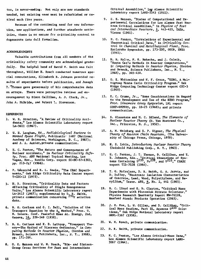
too, is never-ending. Not only are new standards
needed, but existing ones must be refurbished or re-
tired each five years.
Because of the continuing need for new informa-
tion, new applications, and further standards activ-
ities, there is no excuse for criticality control to
degenerate into dull formalism.
ACKNOWLEDGMENTS
Valuable contributions from all members of the
criticality safety ccamunity are acknowledged grate-
fully. The helpful hand of David R. Smith was felt
throughout, William H. Roach conducted numerous spe-
cial computations, Elizabeth B. Johnson provided re-
sults of experiments before publication, and Joseph
T. "Thomas gave generously of hi3 comprehensive data
on arrays. There were perceptive reviews jnd en-
couragement by Dixon Callihan, A. J. Clark, Jr.,
John A. McBride, and Robert I. Stevenson.
REFERENCES
1. W. R. Stratton, "A Review of Criticality Acci-dents," Los Alamos Scientific Laboratory reportLA-3611 (1967).
2. W. H. Laagham, Ed., Rad.-Cobiologi.aal Factors inManned Space Plight, Publicatio•• 1487 (NationalAcademy of Sciences, Washington, D. C , 1967);and J. A. Auxier,private communication.
3. H. C. Paxton, "The Nature and Consequences ofNuclear Accident3," in Nuclear Criticality Safe-ty, Proc. ANS National Topical Meeting, LasVegas, Sev., Sandia Corp. report SC-DC-67-1305,pp. 213-217 (1966).
4. P. Lecorche" and R. L. Seale, "The CRAC Experi-ments," Oak Ridge Criticality Data Center reportY-CDC-12 (1972).
5. W. R. Stratton, "Criticality Data and FactorsAffecting Criticality of Single HomogeneousUnits," Los Alamos Scientific Laboratory reportLA-3612 (1967); supplemented by D. R. Smith,private communication concerning 2 3 3U solutiondata.
6. B. G. Carlson and G. 1. Bell, "Solution of theTransport Equation by the Sn Method," Proc. U.N. Intern. Conf. Peaceful Uses At. Energy, 2nd,Geneva, 16, 539-549 (1958).
7. B. G. Carlson and K. D. Lathrop, "Transport The-ory—The Method of Discrete Ordinates," in Com-puting Methods in Reactor Physics, (Gordon andBreach, Science Publishers, Inc., M. T., 1968),pp. 171-266.
8. G. E. Hansen and W. H. Roach, "Six- and Slxteen-Group Cross Sections for Fast and Intermediate
Critical Assemblies," Lo^ Alamos ScientificLaboratory report LAMS-2543 (1961).
9. G. E. Hansen, "Status of Computational and Ex-perimental Correlations for I.os Alamos Fast Neu-tron Critical Assemblies," in Physic^ of Fastand Intermediate Reactors, 1, 445-455, IAEA,Vienna (1961).
10. H. C. Paxton, "Correlations of Experimental andTheoretical Critical .Data," in Critiaality Con-trol in Chemical and Metallurgical Plant, Proc.Karlsruhe Symposium, pp. 173-205, OECD, ENEA(1961).
11. M. H. Kalos, F. R. Nakache, and J. Celnik,"Monte CarJo Methods in Reactor Computations,"ir. Computing Methods in Reactor Physios, (Gordonand Breach, Science Publishers, Inc., N. Y.,1968), pp. 365-438.
12. G. E. Whitesides and N. F. Cross, "KENO, A Mul-tigroup Monte Carlo Criticality Program." OakRidge Computing Technology Center report CTC-5(1969).
13. E. C. Crume, Jr., "Some Considerations in Regardto the Development and Use of the KENO Program,"Proc. Livevmore Array Symposium, LRL reportCONF-680909, pp. 18-25 (1968)j and privatecommunication.
14. S. Glasstone and M. C. Edlund, The Elements ofNuclear Reactor Theory (D. Van Nostrand Co.,Inc., Princeton, N. J., 1952).
15. A. M. Weinberg and E. P. Wigner, The PhysicalTheory of Neutron Chain Reactors, (The Univer-sity of Chicago Press, Chicago, 1958).
16. H. S. lob in, Introductory Nuclear Reactor Theory(Reinhold Publishing Corp., N. Y., 1963).
17. H. C. Paxton, J. T. Thomas, D. Callihan, and E.B. Johnson, Eds., "Critical Dimensions of Sys-tems Containing U 2 3 5, Pu239, and U 2 3 3," USAECreport TID-7028 (1964).
18. T. G. McCreless, D. R. Smith, G. A. Jarvis, andD. Duffey, "Neutronic Isolation Characteristicsof Concrete, Lead, Wood, Polyethylene, and Be-ryllium," Trans. ANS, 1, No. 2, 441 (1965).
19. R. C. Lloyd and E. D. Clayton, "Critical MassExperiments with Plutonium Nitrate Solution?,"Physics Research Quarterly Report HW-76128,Hanford Atomic Products Operation (1963).
20. J. K. Fox, L. W. Gilley, and D. Callihan, "Crit-ical Mass Studies, Part IX, Aqueous U 2 3 5 Solu-tions," Oak Ridge National Laboratory reportORNL-2367 (1958).
21. W. H. Roach, private communication.
22. D. R. Smith, private communication.
23. H. C. Faxton, "Los Alamos Critical-Mass Data,"Los Alamos Scientific Laboratory report LAMS-3067 (1964).
44

24. W. R. Stratton, "Critical Dimensions of Uranium(93.5)-Graphite-Water Spheres, Cylinders, andSlabs," Los Alamos Scientific Laboratory reportLAMS-2955 (1962),
25. P. M. Wallis, "Computational Survey of Homogene-ous Water-Moderated Systems," Los Alamos Scien-tific Laboratory report LA-3166-MS (1964).
26. W. H. Arnold, Jr., "Critical Masses and LatticeParameters of H2O-UO2 Critical Experiments,"Yankee Atomic Electric Co. report YAEC-152 (1959).
27. P. W. Davison, S. S. Berg, W. H. Bergraann, D. F.Hanlen, B. Jennings, R. D. Learner, and J. E.Howard, "Yankee Critical Experiments—Measure-ments on Lattices of Stainless Steel-CladSlightly Enriched Uranium Dioxide Rods in LightWater," Yankee Atomic Electric Co. report YAEC-94 (1959).
28. W. H. Roach, "Parametric Survey of CriticalSizes," in Technology, Engineering and Safety,Progress in Nuclear Energy, Series IV, _5, 505-533 (1964).
29. D. R. Smith, "Criteria and Evrluation for theStorage of Fissile Material in a Large and Var-ied Reactor Programme," Criticality Control ofFissile Materials, Proc. Stockholm Symposium,pp. 667-675, IAEA Vienna (1966).
30. H. C. Paxton, "Density-Analog Techniques," Proa.Livermore Array Symvosium, LRL report CONF-680909, pp. 6-11 (1968).
31. J. T. Thomas, "A Method for Estimating CriticalConditions for Large Arrays of Uranium," NuclearCriticality Safety, Proc. ANS National TopicalMeeting, Las Vegas, Nev., pp. 189-200 (1966).
32. J. T, Thomas, "Criticality of Large Systems ofSubcritical U(93) Components," Oak Ridge Criti-cality Data Center report 0RNL-CDC-1 (1967).
33. H. F. Finn and N. L. Pruvost, "Livermore Pluto-nium Array Program," Proc. Livermore Array Sym-posium, LRL report CONF-680909, pp. 108-111(1968).
34. J. T. Thomas, "The Effect of Unit Shape on theCriticality of Arrays," Oak Ridge CriticalityData Center report ORNL-CDC-4 (1967).
35. J. T. Thomas, "Some Effects of InterspersedModeration on Array Criticality," Oak RidgeCriticality Data Center report Y-CDC-6 (1969).
36. J. T. Thomas, "Uranium Metal Criticality, MonteCarlo Calculations and Nuclear CriticalitySafety," Oak Ridge Criticality Data Center re-port Y-CDC-7 (1970).
37. 2. B. Johnson and D. F. Cronin, "Critical Di-mensions of Aqueous UO2F2 Solutions Containing4.9% U 2 3 -Enriched Uranium," Neutron PhysicsDivision Annual Progress Report ORNL-3714, JL,31-32, Oak Ridge National Laboratory (1964).
38. R. L. Stevenson and R. H. Odegaarden, "Studiesof Surface Density Spacing Criteria Using KENO
Calculations," ANS Trans. J7, No. 2, 890 (N.v1969).
39. H. F. Henry, J. R. Knight, and C. W. Newlon,"General Application of a Theory of Neutron In-teraction," USAEC report K-1309, Oak Ridge Gas-eous Diffusion Plant (1956).
40. A. F. Thomas and R. A. Scriven, "Neutron Inter-action in Fissile Assemblies," in Technology,Engineering and Safety, Progress in Nuclear En-ergy, Series IV, 3. (Pergamon Press, Inc., N. Y.,1960).
41. C. E. Newlon, "Critical Interaction Potentialsof Water Moderated UFg Arrays," USAEC reportKD-1768, Oak Ridge Gaseous Diffusion Plant (1962).
42. H. K. Clark, "Interaction of Fissionable Units,"Nucl. Sci. Eng. 15_, 20-28 (1963).
43. J. T. Thomas, "The Criticality of Cubic Arraysof Fissile Material," Oak Ridge CriticalityData Center report Y-CDC-10 (1971).
44. Nuclear Safety Guide, Subcommittee 8 of the ASASectional Committee N6, and Project 8 of thaANS Standards Committee, USAEC report TID-7016,Rev. 1 (1961).
45. H. C. Paxton and G. R. Keepln, "Criticality,"The Technology of Nuclear Reactor Safety, 1^,T. J. Thompson and J. G. Beckerley, Eds. (TheMIT Press, Cambridge, Mass., 1964).
46. American National Standard, "Nuclear CriticalitySafety in Operations with Fissionable MaterialsOutside Reactors," ANSI N16.1-1969 (Revision ofN6.1-1964).
47. American National Standard, "Criticality Acci-dent Alarm System," ANSI N16.2-1969.
48. American National Standard, "Safety in Conduct-ing Subcritical Neutron-Multiplication Measure-ments In Situ," ANSI N16.3-1969.
49. American National Standard, "Use of Borosilicate-Glass Raschig Rings as a Neutron Absorber inSolutions of Fissile Material," ANSI N16.4-1971.
50. Proposed standard, "Criteria for Nuclear Criti-cality Safety Controls in Operations whereShielding Protects Personnel," Standards WorkGroup ANS-8.10, draft of June 1972.
51. Proposed standard, "Guide for Nuclear Critical-ity Safety in the Storage of Fissile Materials,"Standards Work Group ANS-8.7, draft of June 1972.
52. H. F. Henry, A. J. Mallett, and C. E. Newlon,"Basic Critical Mass Information and its Appli-cation to K-?-5 Design and Operation," USAEC re-port K-1019, Part 3, Oak Ridge Gaseous Diffu-sion Plant (1955).
53. J. W. Wachter, Ed., "Nuclear Safety Handbook,"USAEC report Y-1272, Y-12 Plant (1963).
54. H. K. Clark, "Handbook of Nuclear Safety,"USAEC report DP-532, Savannah River Laboratory(1961).
45

55. E. D. Clayton, "Nuclear Safety in Chemical andMetallurgical Processing of Plutonium," USAECreport HW-68929, Hanford Atomic Products Oper-ation (1961).
56. F. Abbey, "Manual of Criticality Data; Parts 1,2, 3," AHSB(s) Handbook 5, UKAEA Health andSafety Branch (1967).
57. "Criticality Guide, Part I Introduction to Crit-icality, Part II Regul&tory Practices, Part IIICurves," in French, CEA-R3114, French AtomicEnergy Commission, Saclay (1967).
58. W. Thomas and W. Weber, "Handbook of Critical-ity," in German, Technical University of Munich(1972).
59. B. G. Dubovskiy, et al., "Critical Parameters ofFissionable Materials Systems and Nuclear Safe-ty (A Handbook)," Russian translation, ClearingHou3e for Federal Scientific and Technical In-formation, JPRS: 42,322 (1967).
60. "Criticality Safety of Nuclear Fuel," in Japa-nese, edited by Technical Committee on Criti-cality Safety of Nuclear Fuel Facilities, JapanAtomic Energy Society (1969).
61. "Regulations for the Safe Transport of Radioac-tive Materials," Safety Series No. 6, IAEA, Re-vised Edition (1972).
62. "Transport of Licensed Material," Code of Fed-eral Regulations, Title 10, Part 71 (1965).
63. "Safety Standards for the Preparation of Radio-active and Fissile Material for Transportation,"USAEC Manual Chapter 0529 (1964).
64. "Hazardous Materials Regulations of the Depart-ment of Transportation," R. M. Graziano's Tar-iff No. 25 (1972); includes Code of FederalRegulations, Title 18, Chapter 39.
65. "Reviews of Recent Criticality Experiments andPlans for Obtaining Nuclear Criticality SafetyData," ANS Trans. 11, No. 2, 687-690 (1968).
66. "Nuclear Safety—Tutorial," ANS Trans. 2_s No. 1,11-13 (1969).
67. "Nuclear Criticality Safety—Techniques, Stand-ards, and Administration," ANS Trans. 12, No. 1,325 (1969).
68. "Criticality Problems of Synthetic ActinideElements," ANS Trans. 12_, No. 2,886-888 (1969).
69. "Nuclear Criticality Safety Computations—Tutorial," ANS Trans. 13_, No. 1, 391-394 (1970).
70. "Implications—ANSI Criticality Safety StandardN16.1," ANS Trans. 13, No. 2, 684-686 (1970).
71. "International Developments in CriticalitySafety," ANS Trans. 14, No. 1, 32-36 (1971).
72. "Criticality Safety in the Light-Water ReactorFuel Cycle," ANS Trans. 14, No. 2, 681-686(1971).
73. "Education for Nuclear Criticality Safety," ANSTrans. 1J5, No. 1, 302-306 (1972).
46
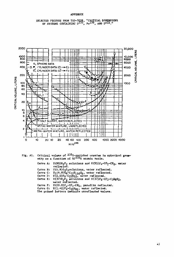
APPENDIX
SELECTED FIGURES FROM TID-7Q28OF SYSTEMS CONTAINING U 2 3 5
"CRITICAL DIMENSIONSPu 2 3 §, AND U233.»
2000 20,000
10,0008000
O, SPHERE DATAD.B, CYLINDER DATA {O—o-E)
d, CYLINDER DATA <cf—»-F)
SALT SLURRY, WATER REFLECTEDI I I I i i I i i in
METAL-WATER MIXTURE, UNREFLECTEDUUL.U
METAL-WATER MIXTURE, WATER REFLECTEO
UJ
20 to ao 40 60 (00 200 400H/UZ35
WOO 2000 4000
Fig. Al. Critical volume of 235(;_enrj.ched uranium in spherical geoic-etry as a function of K/235U atomic ratio.
Curve A: U(93)02F2 solutions and U(95)F4-CF2-CH2, waterreflected.
Curve B: U(4.9)(>2F2Solutions, water reflected.Curve C: U3(4.9)0g-C57H1100g, water reflected.Curve D: U(2.0)F4-C25H52, water reflected.Curve E: U(37)02F2 soJutlons and U(37)F4-CF2-C5H802,
water reflected.Curve F: U(29.8)F4-CF2-CHZ, paraffin reflected.Curve G: U(1.42)F4-C4oH8i, water reflected.The primed letters indicate unreflected values.

t.O
O, UO3.5) METAL CORE, VCCUNREFLECTEO) = 2.6 LITERS
Q, U(93)0PF, SOLUTION, H/U2 3 5 = 73.4,Vc<UNREFLECTED)=M4.0 LITERS
, Uti.42)-PARAFFIN, H / U 2 3 5 = 4 1 8 ,Vc (UNREFLECTED) = 847 LITERS
4 6 8 10THIChMESS OF WATER REFLECTOR, IN.
12 14
Fig. A2. Ratio of water-reflected-sphere to unreflected-sphere crit-ical volumes vs reflector thickness.
48

200
1008060
40
20
H/U23S FOR UO2Fj SOLUTIONS
2000 1000 500 300 200 100 50 30 20
I4u
40.80.6
0.4
0.1
a
ir&
j
j_
j
4
i
T f 1 1
SOLUTIC
V, 6 - |N . STAINLESS
_L
T i - i - f sScu
• " ' O , 0A1' ' ' D , DAI
" T . HY1 ME
1 1
TFR(
NS
WAT
111'DM W2O R£
:R
= !
Rl
^ •
:FLE
4+
ITIACTIVITY
4
t
. . \ .._ I*
COE:FF
r"
' '
IIIICIENl
: 1 ' ^^^MtlAL-WAItH
:TOR
ftr=! —
wixiuHt;.
IA DERIVErA DERIVEDRIDE 0A-
TAL-WAT£
_L
D FROM CYUH
rA REOUCEO T:R MIXTURE
1
JOERS
j
S',
- «!jj—J ^ ^
. - * * • <
.
METAL
!
\
0.01 0.02 0.04 0.1 0.2 0.4 1 2 4 6 6 10
U2 3 5 OENSITY, KG OF U2 J 5 / LITER i : ';
I I j I j _ I I I i I
40
2000 1000 500 300 200 100 50 30 20 10 5 3 2 1 0
H/U2 3 5 FOR METAL-WATER MIXTURES
Fig. A3. Critical masses of homogeneous water-moderated U(93.2)spheres.
49

20.000
tO,000S000
60004000
2000
•000BOO
600400
200
H/U M S FOP UOJFJ SOLUTiOMS
2000 1000 500 300*00 tOO SO 9020
•Xu£u
1008060
40
2C
10
&
5)1
4=j A
i A! *
T~[i
i
-1
I
j
ij
/ATE
i
^ r
a RSFI
1 1
4-
O, OATA DERIVED FROM SPHERESD, OATA DERIVEO FROM CYLiNOERS
. _ T H v n D i n c rtATft ocni ircn TA _ .* IET« L-WATE
, _ FSO
1, | VW - !N. STAINLESS S
O 1
It MIXTUREI
1 MjO REArriv
mi i 1
TEEL REFLECTOR
• ' t
tfa^ ^
SOLUTIONS'
METAL-'.VATF.R FIXTURES
IJ__
J
I
3 *::
J
9 . /
A y\
\
/
\JMETA
1 I 11L
O.Ot 0.02 0.04
I
O.I 0.2 0.4 < 2 4 6 310 20U235 DENSITY, KG OF giSS/UTER
4 0
I J I2000 1000 500 300 200 <00 SO 30 20
U2 iS
JO
H / U 2 i S FOR METAL-WATEH MIXTURES
S 3 2 <
Fig. A4. Critical voltaas of hoaogencous vatcr-oodcraccd U(93.2)spheres.
50

4008060
40
H/U2 5 5F0R U02F2 SOLUTIONS
2000 1000 500 300 ZOO 100 50 30 20
zof
a
az
20
10e6
10.80.6
0.4
0.2
0.1
Jn1 \1 Cl
i, I
a
-\-
- 1 . ,
WA
o,a,
: """I—
v«,-IN STAINLE
, J_jJ 'fER REFLECTOR
UAIA ULNIVtU 1-DATA DERIVED F
L 1 1
ME
ROM SrROM C
J_
JMtKL
SS STEEL F
' " " ^ —••
!EFL
fe;—
EC
••--SOLUTIOMS
1
TOR
TAL-WATERMIXTUM:S'
b
rLINDERS
1 1 iMETAL
0.01 0.02 0.04 O.I 0.2 0.4 1 2 4 6 6 10 20
; U23S DENSITY, KG OF U2 3 5 / LITER
40
L _L J L _L J L2000 1000 500 300 200 100 50 30 20 10 5 3 2 1 0
H/U 2 3 5 FOR METAL-WATER MIXTURES
Fig. A5. Estimated critical diameters of infinite cylinders of homo-geneous water-moderated U(93.2).
51

1008060
40
20
CO O
iS fz 6¥ 4<_itf)
I 1? 0.8
0.6
0.4
0.2
0.1
H/U23SF0R UO2F2 SOLUTIONS
2000 1000 500 300 200 100 50 30 20
0
IH
H"11"1
• •
1
l\! ISK
1
-t"
v.
|
L
ST. -
1 iUJI I I
' " ' 0 , DATA DERIVED FROM SPHERES
D, DATA DERIVED FROM CYLINDERS
" ' ' A , DATA DERIVED F
I n - IS
WATER RE1
ROM SLABS
TSOLUTIONS,, 1 IIH
rLEC
J .
NTO^1? T
M
<
FTAL-WATMIXTURES'^
I I
i
1-ivr-l-—N+-
|METAL)
r
i i0.01 0.02 0.04 0.1 0.2 0.4 1
U235 DENSITY, KG OF U2 3 5 / LITER
I
4 6 8 10 20 40
I I2000 1000 500 300 200 100 50 30 20 10
H/U235 FOR METAL-WATER MIXTURES
5 3 2 1
Fig. A6. Estimated critical thicknesses of infinite slabs of homoge-neous water-moderated U(93.2).
52

H/Pu FOR IDEALIZED SOLUTIONS30*00 2000 (000 500 300 200 100
100 -80 -
iO V
8 -
6 -
\ -
0.8 -
0 2 -
n * -
T
D, DAT/A, DAT^
J, DAT/
!
i >>—%t -zfs1 \1
1
we
k DERIVEDk DERIVEDk DERIVEDk DERIVED
'II,,,I I I1
FROM CRITIC*FROM CRITIC*FROM SUBCR
FRO
V,6- IN. STAINLSTEEL REFLECPu 2 3 9 , NO NITf
_1
D£•Ji
M SUBCR
SOL
ESS
(ATE/
1 1
I50 30 20
!
kL SPHEREiL CYLINDTICAL CYlTICAL CYl
JTIONS
///
W
Pi
II:s
ERS
.INDERS
.INDE
mt
*
ATEFJ239 |
:RS
\ *
- J — ^'(. ^
r
REFLECT
NO NITRA
1
3R,"
TE
|
METMl
L"^T—'"C
ftL-WATER JXTURES
1
11
r METAL 1|
1
j1
i i0.006 0.01- 0.02 0.04 0.1 0.2 0.4 1 2 4
! : PLUTONIUM DENSITY, KG OF PLUTONIUM/LITER
I L I I I I I L J L
6 8 10 20 30
J I3000 2000 (000 500 300 200 100 50 30 20 10 5
H/Pu FOR CI-PHASE PLUTONIUM-WATER MIXTURES
3 2 1
Fig. A7. Critical masses of homogeneous water-moderated plutonium
spheres.
53
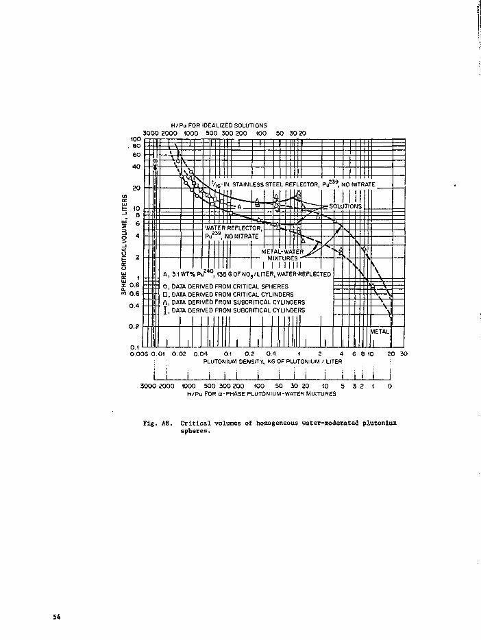
100. 80
6040
20
(086
H/Pu FOR IOEALIZED SOLUTIONS3000 2000 1000 500 300 200 100 50 30 20
§
ya.oUJ
£Ia.V)
* i<'l! \4 ^
1
1
j
V
tilt
K1V
bs
• Pi
-E:
#
piWATE
1
-IN. STAINLESS STEEL REFLECTOR, P j 2 3 9 , NO NITRATE
R RFFLPC7
, 135 G OF NO
OR,TE, ,
METAL-VM
rER,WATE
IIR-REFLEC1
- S
rED
O, DA A utmvtu rnuiw LKI I IUAL b^ritwts- " [ 0 , DATA DERIVED FROM CRITICAL CYLINDERS
A , DATA DERIVED FROM SUBCRITICAL CYLINDERS
1 I , DATA DERIVED FROM SUBCRITICAL CYLINDERS
! i | 1
I
1 1 1
ITIONJ
A'
.V\ V
\
METAL
1
0.80.60.4
o.a
0.10.006 0.01 0.02 0.04 0.1 0.2 0.4 1 2 4
PLUTONIUM DENSITY, KG OF PLUTONIUM / LITER6 8 10 20 30
I L J I J I I I ! I3000 2000 1000 500 300 200 100 50 30 20 10 5
H/Pu FOR a-PHASE PLUTONIUM-WATER MIXTURES
3 2 1
Fig. A8. Critical volumes of homogeneous water-moderated plutoniumspheres.
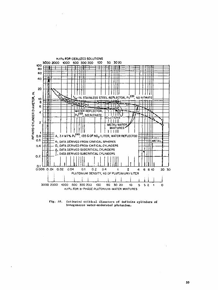
1008060
40
H/Pu FOR IDEALIZED SOLUTIONS3(300 2000 1000 500 300 200 100 50 30 20
2ofUJ
sSQ
<rUiQ
z
>-
20
10.80.60.4
0.2
CO
- 4 - —A, 3
I °i n
1 D D- ' AD
li I.°
I 1
Ur
1
E:: 1
. STAINLEfcd=fc 1
-f
5SShTT"
rEE
WATER REFLECTOR,Pu2 3 9 NO NITRATE 1
:LREF
iOLUT
MET/Ml)
1
1
LECTOR, Pi
\\K)ONS
^L-WATER,,
III
239
T//
NC
h
.1 W1 % Pu , 130 b Uh IMO3/LITER, WATER REFLECTED
ATA DERIVED FROM CRITICAL SPHERESATA DERIVED FROM CRITICAL CYLINDERSATA DERIVED SUBCRITICAL CYLINDERSATA DERIVED SUBCRITICAL CYLINDERS
j _ II I I , ,1III 1
i NITR/
k
^TE
" METAL
i
0.10.006 0.01 0.02 0.04 0.1 0.2 0.4 1 2 4
PLUTONIUM DENSITY, KG OF PLUTONIUM/LITER6 8 10 20 30
..I . I L J I I I3000 2000 1000 500 300 200 100 50 30 20 10 5
H/Pu FOR a-PHASE PLUTONIUM-WATER MIXTURES3 2
Fig. A9. Estimated critical diameters of infinite cylinders ofhomogeneous water-moderated plutonium.
55
10080
60
40
20
1086
H/Pu FOR IDEALIZED SOLUTIONS3000 2000 1000 500 300 200 100 50 3020
10.80.6
0.4
0.2
=HA, 3.1 WT% Pu240, 135 G OFNOj/LITER, WATER REFLECTED
• O, DATA DERIVED FROM CRITICAL SPHERES• , OATA DERIVED FROM CRITICAL CYLINDERSA, DATA DERIVED FROM SUBCRITICAL CYLINDERSI , DATA DERIVED FROM SUBCRITICAL CYLINDERS
V,6-IN. STAINLESS STEEL REFLECTOR, Pu , NO NITRATE
WATER REFLECTOR,Pu239, NO NITRATE
0.40.006 0.01 0.02
I I
0.04 0.1 0.2 0.4 1 2 4PLUTONIUM DENSITY, KG OF PLUTONIUM / LITER
6 8 10: 20 30
J I J I I I I I
3000 2000 1000 500 300 200 100 50 30 20 10 5H/Pu FOR a-PHASE PLUTONIUM-WATER MIXTURES
3 2
Fig. A10. Estimated critical thicknesses of infinite slabs of homo-geneous water-moderated plutonium.
56
u.oo
sf<t
1008060
40
20
10B6
H/U J 3 3 FOR UO2Fg SOLUTIONS
2000 1000 500 300 200 100 50 30 20
P 2
0.80.60.4
0.2
0.10.01 0.02 0.04 0.1 0.2 0.4 1 2 4
* 11 r*m*iTw L// fie 11233 t
6 8 10 20
J L
' DENSITY, KG OF U / LITER
_J LJ L_ LJ_2000 1000 500 300 200 100 50 30 20 10
H/U 2 3 3 FOR METAL-WATER MIXTURES
5 3 2 1
40
Fig. All. Critical masses of homogeneous water-moderated U spheres.Dashed symbols represent less certain values.
57

1000800600400
2 0 0
H/U2 3 3 FOR UO2F2 SOLUTIONS
2000 1000 500 300 200 400 50 30 20.IT
ERS
ME
, I
3§- i
S
RIT
l
uUJre
1008060
4 0
20
108
6
4
10.80.60.4
0.2
0.10.01 0.02 0.04 O.\ 0.2 0.4 ) ;
U 2 3 3 DENSITY, KG OF U 2 3 3 / LITER
I J I I I I
4 6 8 10
I I I I
20
2000 1000 500 300 200 100 50 30 20, .233
10 5 3 2 1 40
H/U " FOR METAL-WATER MIXTURES
Fig. A12. Critical volumes of homogeneous water-moderated IIspheres. Dashed symbols represent less certain values.
58

100eo
60
40
20
H / U 2 3 3 FOR -UOgFj SOLUTIONS
2000 1000 500 300 200 100 50 30 20
a.iiUJ
Q
1
0.80.6
0.4
0.2
0.10.04. 0.02 0.04 0.1 0.2 0.4
U 2 3 3 DENSITY, KG
I I I I I J_
OFU2
j L
33/ LITER
j
4 6 8 10
I I I I
2 0
2000 1000 500 300 200 100 50 30 20 10
H/U233 FOR METAL-WATER MIXTURES
5 3 2 1
4 0
Fig. A13. Estimated critical diameters of infinite cylinders of homo-geneous water-moderated 233u, Dashed symbols representless certain values.
59

H/U233 '
V)
SiuX
zCz
400
806040
20
6
4
2
OR0.6
0.4
0.2
0.1O.C
2000—)
t\
I
10C
—
—
I
0
* !D,
1
w
500 300 200
1
DATA DERIVED FtDATA DERIVED FFDATAC
ATER1
)1; 0.02 0.04
1 1
)ERIVED FF
REFLECTOI
1 1
10C
—
)
?0M SP?0MU0?0MU0
M.ST
|
Air
w
I
50 3
Hi
2 F
JL
0.1 0.2 0.4
U 2 3 3 DENSITY
I I
0 20
RES
s CYLINDERSMOJ)J
ESS
I
1
CYLINDE
STEEL RE
as •
FLECTO
I I I—N-
I SOLUTIONSII
I I
ETAL-MIXTt
"* • » ,
WATERJRES
'"•. I
N ij
NMETAL
III '1 2 4 6 6 10 20
KG OF U2 3 3 / LITER : i j i
i i i i i i i i
4 0
2000 1000 500 300 200 100 50 30 20 10 5 3 2 1
H/U233 FOR METAL-WATER MIXTURES
Fig. A14. Estimated critical thicknesses of infinite slabs of homo-geneous water-moderated 2 3 3U. Dashed symbols representless certain values•
60

4000
EOOO
1000
800
600
400
200
400
80
60
40
20
10
1'//UlXoccUJJ<
p£uozpi
I(
r
V1\\
s
O, FROM CRITICAL CYLIfJDED, FROM CRITICAL SPHERESA, FRO
con
• &
ICKURANIUI\
W EXPJMNS
NOR
N
REFL
^NE^
:FLE
\
ECTO
TIA
;TO
R
L
R
s
v
RS
S
IT
S358 10 20 40 60 80 100
U S 3 5 ENRICHMENT OF URANIUM METAL,
Fig. A15. Critical mass vs Z 3 5U enrichment of uranium metal. Theshaded strip represents the range of uncertainty in thevalue of "5JJ enrichment below which uranium metal cannotbe made critical.
61

O
s
_u5o
V)
4000
2000
1000800600
400
200
1008060
40
20
1086
1 III 1 1 IIIO, H,0 [pa = 1.00 G/CM )D, D20 (/fc= 1.11 G/CM3)7 , BERYLLIUM (/>„ = 1.65 G/CM3)
1 0 , GRAPHITE ( / > O - 1.67 G/CM3)
jf
^ * '
Tif
\-L
V
r
>-
1
f
-,/
_y"
-y —
\
1
O.OOO1 0.001 0.01 0.1VOLUME FRACTION OF U235AT 17.53 G/CM3
Fig. A16.Critical masses of unreflected spheres of U(93) dilutedwith moderating materials.
62
1000800600
O, SPHERE DATAD, CYLINDER DATA (0—»-E>
, CYLINDER DATA (d——
SALT SLURRY,WATER REFLECTED
METAL-WATER MIXTURE,WATER REFLECTEDI I I I I
METAL-WATER MIXTURE,UNREFLECTED
60 100 200 400 1000 2000 4000 10,000
H/U,235
Fig. A17. Critical mass of U-enriched uranium in spherical geom-etry as a function of H/ U atomic ratio.
Curve A: U(93)O2F2 solutions and U(95)F4-CF2-CH2,water reflected.
Curve B: U(4.9)O2F2 solutions, water reflected.Curve C: u3(^-9)°8"c57Hno<'6' w a t e r reflected.Curve D: U<2.0)F4-C25Hg2> water reflected.Curve E: U(37)O2Fg solutions and U(37)F4-CF2-C5H8<)2,
water reflected.Curve F: U(29.8)F4-CF2-CH2, paraffin reflected.Curve G: U(1.42)F4-C^0H8i, water reflected.
The primed letters indicate unreflected values.
63

60
40
20
u. 10
g 8
s 6
sOt -5
S
1
0.8
0.60 2 5 10 20
URANIUM ENRICHMENT, WT.% U 2 3 550 100
235Fig. A18. Minimum critical mass as a function of U enrichment
in hydrogen-moderated systems.
64
1000
500
200
LIMITING CRITICALENRICHMENT,
HETEROGENEOUS-HOMOGENEOUS-
I
-V
50 Y .— SOLUTION, UNREFLECTED
20
HETEROGENEOUS,WATER REFLECTED -
\\SOLUTION,WATER REFLECTED
s\\\
\0.1 02 OS 1 2 5 10
URANIUM ENRICHMENT, WT.% U83920 50 100
235Fig. A19. Minimum critical volume as a function of 0 enrich-
ment in hydrogen-moderated systems.
65

200
100
g 80
p=r 6o
«5KUJ
a
z
£
Z
40
20
40.5
_
1
• HETE
— HO
I1i\\
\V \
WGEN
MOGEf
EOU
JEOL
5 L
ISL
1MrIM
•
T
JO
« • •
• - .
LUT
T
ON, UNREFL
" '
" *^ ^^HETEROGENEOUS, WATER REFLECTEO ^ T >
1 I I IMil
ECTEC
——>
SOLUTION, WATER REFLECTED--
)
• » —
y
=
/
mm
s X
s; r
5 \0URANIUM ENRICHMENT, WT.% U1
20235
50 100
Fig. A20. Minimum critical cylinder diameter as a function of235y enrichment in hydrogen-moderated systems.
66

aoI
§
3
200
100
80
60
40
20
108
6
4
z
10.8
0.60.5 5 10 20
URANIUM ENRICHMENT, WT% U 2 3 550 100
Fig. A21. Minimum critical slab thickness as a function of 235Uenrichment in hydrogen-moderated systems.
67
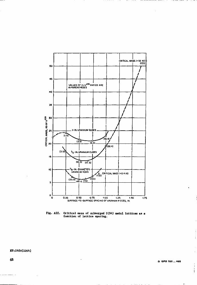
0.25 0.50 0.75 1.00 1.25 1.50 1.75SURFACE-TO-SURFACE SPACING OF URANIUM PIECES, IN.
Fig. A22. Critical mass of submerged 0(94) metal lattices as afunction of lattice spacing.
KI:lii8O(iaolt)
68•ft GPO 712 — 4«S