Critical Power: Generators and Generator System Design
56
Critical Power: Generators and Generator System Design Sponsored by:
-
Upload
consultingspecifyingengineer -
Category
Education
-
view
1.903 -
download
1
Transcript of Critical Power: Generators and Generator System Design
Critical Power: Generators and Generator System Design
Sponsored by:

Today’s Webcast Sponsor:
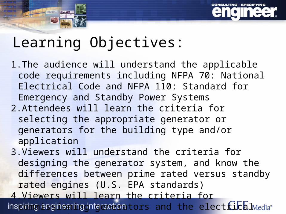
Learning Objectives:
1.The audience will understand the applicable code requirements including NFPA 70: National Electrical Code and NFPA 110: Standard for Emergency and Standby Power Systems
2.Attendees will learn the criteria for selecting the appropriate generator or generators for the building type and/or application
3.Viewers will understand the criteria for designing the generator system, and know the differences between prime rated versus standby rated engines (U.S. EPA standards)
4.Viewers will learn the criteria for commissioning generators and the electrical systems they support.

Robert R. Jones Jr., PE, LEED AP, JBA Consulting Engineers,Las Vegas, Nev.
James Ferris, PE, TLC Engineering for Architecture, Orlando, Fla.
Moderator: Jack Smith, Consulting-Specifying Engineer and Pure Power, CFE Media, LLC
Presenters:

Critical Power: Generators and Generator System Design
Robert R. Jones Jr., PE, LEED, APJBA Consulting Engineers,
Las Vegas, Nev.
James Ferris, PE, TLC Engineering for Architecture,
Orlando, Fla.

Codes & Standards• IBC
– Chapter 27: Electrical
• NFPA 110: Emergency & Standby Power Systems
• NFPA 101: Life Safety Code• NFPA 70: National Electrical Code
– Article 445: Generators– Article 700, 701, & 702: Systems

IBC – 2012 Edition
• Chapter 27 addresses electrical components, equipment, and systems
• 2702.1 - Emergency and Standby Systems shall be installed per NFPA 110
• 2702.2 – Emergency and Standby Systems shall be installed where required

NFPA 110 – 2013 Edition• Definitions (NFPA 110 Chapter 3)
– Emergency Power Supply (EPS): “The source of electrical power of the required capacity and quality for an emergency power supply system (EPSS).”
– Emergency Power Supply System (EPSS): “A complete functioning EPS system coupled to a system of conductors, disconnecting means and overcurrent protective devices, transfer switches and all control, supervisory and support devices up to and including the load terminals of the transfer equipment needed for the system to operate as a safe and reliable source of electric power.”
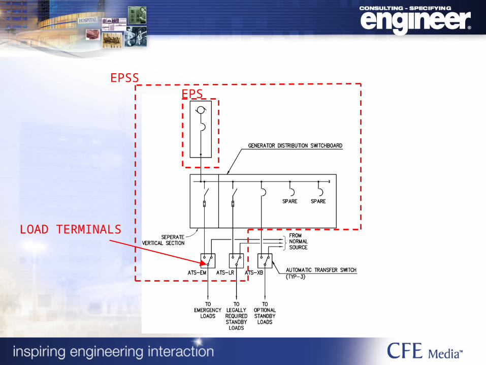
LOAD TERMINALS
EPSEPSS
NFPA 110 – 2013 Edition
• Chapter 4: EPSS Classification– Class: Minimum time to operate without
refueling/recharging.– Type: Maximum time to re-energize loads.– Level: Installation, performance, and
maintenance criteria.

NFPA 110 – 2013 Edition
• Class– Defined in hours per applicable code, application
and AHJ.– Battery System
• NEC Article 700.12(A): 1.5-hour minimum, Class 1.5.
– Generator System• NEC Article 700.12(B)(2): 2-hour minimum, Class 2.• NFPA 20 Chapter 9.6.2.3: 8-hour minimum, Class 8.• AIA Guidelines for Design and Construction of
Healthcare Facilities (Joint Commission requirement): 24 hours minimum, Class 24.

NFPA 110 – 2013 Edition
• Type– Defined in seconds per applicable code,
application and AHJ.– NEC Article 700.12: 10 seconds maximum,
Type 10.– NFPA 20 Chapter 9.6.2.1: 10 seconds
maximum, Type 10.– NEC Article 701.12: 60 seconds maximum,
Type 60.

NFPA 110 – 2013 Edition
• Level 1– Required where EPSS failure “could result in loss of
human life or serious injuries.”– NEC Article 700: Emergency System.– NEC Article 701: Legally Required Standby (NFPA 101
7.14.7.1)– NEC Article 517: Chapter 3 Essential Electrical System.
• Level 2– Required where EPSS failure “is less critical to human
life and safety.”– NEC Article 701: Legally Required Standby.

NFPA 101 – 2012 Edition• Type 10, Class 1.5, Level 1 for emergency lighting
(7.9.2.2)• Type 60, Class 2, Level 1 for occupant evacuation
elevators (7.14.7.1)• Type 60, Class 1, Level 1 for high-rise standby power
(legally required)– Electric Fire Pump– Jockey Pump– Air Compressor for dry-pipe/pre-action fire suppression system– Emergency Command Center– At least one elevator serving all floors– Mechanical Smoke Control

NEC (NFPA 70) – 2011 Edition
• Article 445: Generators– The ampacity of conductors from each
generator to the first overcurrent device must be at least 115% of the nameplate current rating (NEC 445.13)
– One or more disconnects with means of locking in the open position are required (NEC 445.18)

NEC (NFPA 70) – 2011 Edition• Article 700: Emergency Systems
– EPS capacity shall be capable of supplying all emergency system loads simultaneously (NEC 700.4(A))– EPS may serve loads other than emergency if capacity and rating can support all connected loads
simultaneously or transfer equipment incorporates selective load pickup and load shedding.– Requires automatic transfer switches that supply only emergency loads (NEC 700.12(A) & 700.12(D))– Wiring shall be contained in separate raceways, enclosures, etc. from all other systems. Separate
vertical switchboard section required when emergency source serves multiple systems (NEC 700.10(B))
• Article 701: Legally Required Standby Systems– EPS capacity shall be capable of supplying all legally required standby loads intended to operate
simultaneously (NEC 701.4)– Requires automatic transfer switches (NEC 701.12(A)– Transfer switches require load shedding capability if generator capacity is not sized to supply all
connected loads at once (NEC 701.4)
• Article 702: Optional Standby Systems– Permanent installations require manual or automatic transfer switches (NEC 702.5)– Transfer switches require load shedding capability if generator capacity is not sized to supply all
connected loads at once (NEC 702.4(B)(2))

TO GENSET CONTROL PANEL FOR SELECTIVE LOAD PICKUP AND SHEDDING
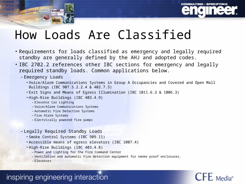
How Loads Are Classified• Requirements for loads classified as emergency and legally required standby are
generally defined by the AHJ and adopted codes.• IBC 2702.2 references other IBC sections for emergency and legally required standby
loads. Common applications below.– Emergency Loads
• Voice/Alarm Communications Systems in Group A Occupancies and Covered and Open Mall Buildings (IBC 907.5.2.2.4 & 402.7.3)
• Exit Signs and Means of Egress Illumination (IBC 1011.6.3 & 1006.3)• High-Rise Buildings (IBC 403.4.9)
– Elevator Car Lighting– Voice/Alarm Communications Systems– Automatic Fire Detection Systems– Fire Alarm Systems– Electrically powered fire pumps
– Legally Required Standby Loads• Smoke Control Systems (IBC 909.11)• Accessible means of egress elevators (IBC 1007.4)• High-Rise Buildings (IBC 403.4.8)
– Power and Lighting for the Fire Command Center– Ventilation and automatic Fire detection equipment for smoke proof enclosures.– Elevators
Local AHJ Considerations
• Some AHJs amend codes and standards before adopting them. This may result in load classifications varying from region to region.
• Example:– Southern Nevada AHJs amended the first
paragraph of NEC 700.1; scope to include specific references to loads that may be connected to the emergency system. Many of these loads would be considered Legally Required Standby in other regions.

Research Codes System Capacity and Use

System Design Sequence
1
•Determine/Estimate Total Load of proposed system
•Determine Load that is Required by Code to be on
2
•Plan for anticipated Run Time for the system
3
•If the System is an emergency system, will it be used for Utility Peak shaving program
4
•Review Fuel Source availability, Quantity of Generators, and Redundancy
5
•Determine appropriate Accessories for the system

• Running kVA– Calculated Electrical Loads + Metered
Electrical Loads
• Starting kVA– What is the biggest starting kVA block (i.e. a
chiller system)
• Special considerations– High harmonic content– Intermittent starting
Generator Selection and Sizing

Metered Electrical LoadsNEC 220.87 (125% Rule)• NEC requires that the existing loads are
metered to determine the “maximum demand continuously recorded over a minimum 30-day period,” and then use 125% of that number as the “existing” load for the system.
• Maximum demand is measured as the average power over a 15-minute period.

Generator Ratings
• Standby Power:– Maximum output is available for non-programmed power
outages.– Average demand during outages should not exceed
continuous rating of generator.– Typical usage of 200 hrs/yr; max expected usage of 500
hrs/yr.
• Prime Power:– De-rated capacity, typically 10% reduction from standby
power rating.– Maximum output available for varying loads for all
outages. – Average demand should not exceed continuous rating.
• Continuous Power– Maximum output available at all times.– De-rated capacity, typically a 15% reduction from prime
power ratings.

Generator De-Rating
– A prime generator is essentially a standby generator de-rated plus additional accessories. The same generator de-rated again is a continuous duty.
– 2000 kW standby = 1825 kW prime = 1600 kW continuous
– But with prime and continuous ratings, everything is bigger: generators, space to accommodate, air intake requirements, fuel consumption, but with less capacity.

Warranty Issues
• What does all of this have to do with my warranty?– Standard warranty for generators are
defined by run hours and length of time, and typically include the rating of the generator.
– Warranties generally do not include:• Use of standby generators in prime
applications• Use of blended fuels such as a natural
gas/diesel mixture• Excessive overloading of the generator.

Generator Tier RatingsTier 2 Tier 4
Emergency Systems can be tier 2 when used for Emergency Purposes only.
Emergency Systems must be tier 4 if they also participate in a Peak Shaving program that the utility uses for financial gain (they can sell power for more than you get paid).
Can remain tier 2 even if they join a “emergency demand response” program offered by the Utility Provider.
Tier 4 requires additional capital investments and additional equipment.
Maximum Run time, testing time, and demand response time criteria.
Per Today’s rules - A new Tier 2 generator installed today CANNOT ever be modified to be a Tier 4 Generator.

Researched Codes
System Capacity and Use
Select a System

Types of Generators
• Portable• Stationary Standby
– Diesel– Liquid Propane– Natural Gas– Dual Fuel.

Fuel Considerations
• On-site fuel storage NEC 700.12(B)(3)• Dual Fuel (or Bi-fuel)
– Can provide an extended runtime.– Usually an aftermarket retrofit to a diesel generator.
Although, some manufacturers do have a factory assembled and tested bi-fuel systems.
– Typically achieves a 40%/60% split.
• Fuel Polisher– Diesel fuel will foul when stored more than 3 to 6 months
without conditioning or detergent additives.– This presents an issue for large on-site fuel storage
systems.

Location
• Indoor– EPS shall be located in a dedicated room with 2-
hour fire resistance rating (NFPA 110 Chapter 7.2.1)– EPSS equipment may be located in EPS room
(NFPA 110 Chapter 7.2.1.2)
• Outdoor– Requires weatherproof enclosure (NFPA 110
Chapter 7.2.2.1)– EPSS equipment may be located within the EPS
enclosure (NFPA 110 Chapter 7.2.2.3)
How many generators?
• Several reasons to consider more than one generator.– Physical Space.– Redundancy/Resilience.– Phased expansion.

Redundancy
• Data centers, hospitals, large-scale hospitality resorts, municipal command centers, etc.
• N+1, 2N• Multiple priorities• Real-time demand load management
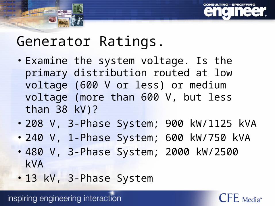
Generator Ratings.• Examine the system voltage. Is the primary
distribution routed at low voltage (600 V or less) or medium voltage (more than 600 V, but less than 38 kV)?
• 208 V, 3-Phase System; 900 kW/1125 kVA• 240 V, 1-Phase System; 600 kW/750 kVA• 480 V, 3-Phase System; 2000 kW/2500 kVA• 13 kV, 3-Phase System

Generator Accessories
• Typical Package Generator– Jacket Heater – Battery Charger – Daytank Controls
• Other Considerations– Remote Radiator
• Radiator Fan• Aftercooler Water Pump
– Motorized Dampers– Remote Fuel Pumps

Researched Codes
System Capacity and Use Select a System Installation and
Commissioning

EPSS Commissioning
Generator
Remote Alarm Annunciation
Fuel System Performance
Parallel Switchgear (if applicable)
Load Shedding
Switchgear “Features”

Generator Assembly
• Load Bank Testing• Sound Testing• Emissions Testing• Accessory Review and Testing
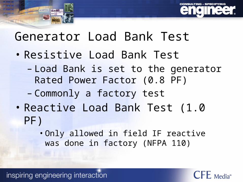
Generator Load Bank Test
• Resistive Load Bank Test – Load Bank is set to the generator Rated
Power Factor (0.8 PF)– Commonly a factory test
• Reactive Load Bank Test (1.0 PF)• Only allowed in field IF reactive was done in
factory (NFPA 110)

Generator Load Bank Test
• NFPA 110 minimum load bank test.• 2 hours at full load.• 5 minute cool down.• Full rating block load to start the second half.
Take a wave capture of the unit performance during the block load.
• 2-hour run at full load.• Recordings every 15 minutes for the duration
of the test.

• Sound Testing– Sound criteria requirements at certain locations
• Air Performance– Sufficient air to the generator engines– Emissions too close to an intake– Air emissions testing
• Generator Accessories– Battery charger goes back on with generator power– Jacket heater turns off when unit is running

Alarm Annunciation
• Alarms annunciate at Unit Mounted Controller (CV)
• Alarms Annunciate at Remote Annunciator (RA)
• Doesn’t address parallel system alarms!
• Per NFPA 110 and NFPA 99
Alarm CV S RA
(a) Overcrank X X X
(b) Low Water Temp. <70oF (21oC) X X
(c) High Engine Temp Prealarm X X
(d) High Engine Temperature X X X
(e) Low Lube Oil Pressure Prealarm X X
(f) Low Lube Oil Pressure X X X
(g) Overspeed X X X
(h) Low Fuel Main Tank (@ 48 hrs. fuel remaining) X X(i) Low coolant level X X
(j) EPS Supplying Load X
(k) Control or Test Switch Not in Auto. Position X X (l) High Battery Voltage X
(m) Low cranking voltage X X
(n) Low Voltage in Battery X
(o) Battery charger ac failure X
(p) Lamp Test X
(q) Audible Alarm Silencing Switch X
(r) Low Starting Air Pressure X
(s) Low Starting Hydraulic Pressure X
(t) Air Shutdown Damper when used X X X
(u) Remote Emergency Stop X
(v) Day tank Hi-low Alarm X X
(w) Leak detection inner cavity of skid mount fuel tank X X
(x) Remote Radiator Breaker Position X X
KEY:
CV Control panel-mtd. visual indication
RA Remote Audible
S Shutdown of EPS
X Required

Alarm Annunciation
• Most alarms can be simulated at the generator, and verified at the annunciator.
• Must include audible and visual annunciation at remote location.
• Recommend adding parallel switchgear (EPSS) alarms where used.
• Other codes supplement this too, such as high-rise requirements in NFPA 101.

Fuel System Performance
• Verify each day tank if used can call for fuel individually and generators are getting correct amount of fuel.
• Verify low fuel alarm is set to the appropriate point and works.

Low fuel Settings• Required Generator
Class = Required Low Fuel Setting
• Class 48 = 48 hrs of fuel• Class 10 = 10 hrs of fuel• 48 hrs x Generator
Hourly Consumption = Low Fuel Level Alarm
Low Fuel Alarm

Parallel Switchgear Commissioning
• Multiple Generators Operating as a system so…
• Complete System operation must be checked!
• Manufacturers can use PLC inputs or potentially PC overrides to “simulate” system loads.

Parallel Switchgear Functions
• Load Shed – Function where Transfer Switches are assigned a different priority– Essential System would be a 1.– Equipment loads may be a 2.– Non-essential may be a 3.
• Usually will relate to the number of generators on the bus.
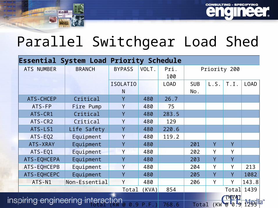
Parallel Switchgear Load ShedEssential System Load Priority Schedule
ATS NUMBER BRANCH BYPASS VOLT. Pri. 100 Priority 200 ISOLATION LOAD SUB No. L.S. T.I. LOAD
ATS-CHCEP Critical Y 480 26.7 ATS-FP Fire Pump Y 480 75
ATS-CR1 Critical Y 480 283.5 ATS-CR2 Critical Y 480 129 ATS-LS1 Life Safety Y 480 220.6 ATS-EQ2 Equipment Y 480 119.2 ATS-XRAY Equipment Y 480 201 Y Y ATS-EQ1 Equipment Y 480 202 Y Y
ATS-EQHCEPA Equipment Y 480 203 Y Y ATS-EQHCEPB Equipment Y 480 204 Y Y 213ATS-EQHCEPC Equipment Y 480 205 Y Y 1082
ATS-N1 Non-Essential Y 480 206 Y Y 143.8 Total (KVA) 854 Total (KVA) 1439
Total (KW @ 0.9 P.F.) 768.6 Total (KW @ 0.9 P.F.) 1295
Total Priority 100 + 200 Loads (KW) 2063.9 Capacity 3000

Parallel Switchgear CommissioningSample Switchgear Commissioning Document (Partial)
Mode: Bus Optimization Off / Generator Demand Off (with Amp Generator)Operation: Generators will load each priority level as a block. The quantity of priority Blocks connected is the same as the priority block connected. If a generator fails, the block associated with that generator will shed.
Scenario 1: Startup. Turn off Normal power, system should call for start. Priority 1 loads will transfer within 10 seconds. Priority 2 will transfer after their associated time delays.
Scenario 2: Second Generator Failure – Priority two Block Loads shed. Turn Second Gen back on and all Priority 2 loads add in one block.
Scenario 3: Gen 1,2 Operating. System Bus overload of 105 % over two generators simulated by a 4-20ma generator. (3000 kW * 1.05 = 3150 kW); Priority 2 loads should shed in descending priority & sub priority order.
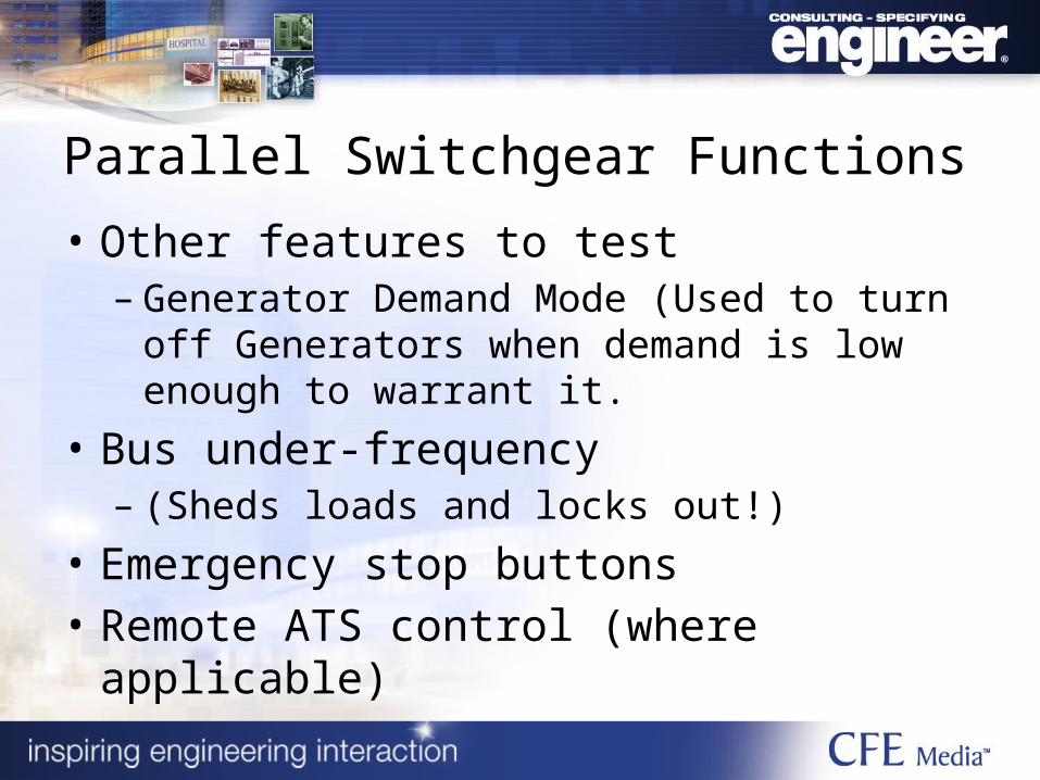
Parallel Switchgear Functions
• Other features to test– Generator Demand Mode (Used to turn off
Generators when demand is low enough to warrant it.
• Bus under-frequency – (Sheds loads and locks out!)
• Emergency stop buttons• Remote ATS control (where applicable)
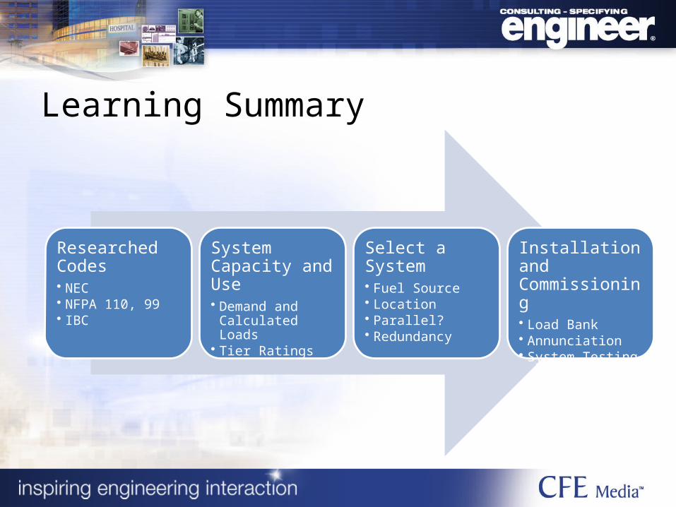
Learning Summary
Researched Codes• NEC• NFPA 110, 99• IBC
System Capacity and Use• Demand and
Calculated Loads• Tier Ratings
Select a System• Fuel Source• Location• Parallel?• Redundancy
Installation and Commissioning• Load Bank• Annunciation• System Testing

Code References
• International Building Code• NFPA 20• NFPA 70 (NEC)• NFPA 99• NFPA 101• NFPA 110

Robert R. Jones Jr., PE, LEED AP, JBA Consulting Engineers,Las Vegas, Nev.
James Ferris, PE, TLC Engineering for Architecture, Orlando, Fla.
Moderator: Jack Smith, Consulting-Specifying Engineer and Pure Power, CFE Media, LLC
Presenters:

Thanks to Today’s Webcast Sponsor:

Webcasts and Research
• Critical Power: Standby Versus Emergency Power Systems
• Critical Power: Standby Power for Mission Critical Facilities
• 2013 Electrical/Power Research Study

Critical Power: Generators and Generator System Design
Sponsored by: