Critical Points Layouts For Storage Ring and Beamlines Ken Chow March 14, 2014.
15
Critical Points Layouts For Storage Ring and Beamlines Ken Chow March 14, 2014
-
Upload
jonas-hilary-miles -
Category
Documents
-
view
214 -
download
0
Transcript of Critical Points Layouts For Storage Ring and Beamlines Ken Chow March 14, 2014.

Critical Points Layouts For Storage Ring and Beamlines
Ken Chow
March 14, 2014

Critical Points Layouts | March 2014(2)
Outline
• Purpose: the general concept of managing “critical points”• Coordinate systems• Source points
– Bend magnets– Superbend magnets– Insertion devices
• Modeling: critical points model• Critical points layout drawing• Theoretical vs. actual points• Ownership guidelines

Critical Points Layouts | March 2014(3)
Purpose: critical points minimize confusion
• There are components whose position impacts performance of ALS storage ring and beamlines
– Storage ring components:• Magnets on the storage ring lattice• Insertion devices in the straight sections (wigglers, undulators, elliptical polarization
undulators)• Masks, stops, diagnostics
– Beamline components:• Mirrors• Slits• Diagnostics
– Locations of these components are called “critical points”
• We actively manage critical points for:– Accuracy in positioning or locating critical components– Clarity when communicating locations of critical components to different
team members– Controlling change and updates as design matures

Critical Points Layouts | March 2014(4)
Coordinate systems (at the ALS)
• ALS Global– Master coordinate system– X=15xx, Y=35xx, Z=25xx (in meters)– Origin (storage ring center) is at (1500, 3500, 2500)– Defined to eliminate axis confusion (i.e. any
coordinate value that starts with “25” is in the Z direction)
– Defined to eliminate negative values
• ALS CAD– Same as ALS Global but with origin moved– Used in CAD systems for global layouts
• ALS Beamline (R,S,T)– Origin and direction defined in ALS Global– All beamline component locations defined in RST
coordinate system
• Fiducial coordinate system (U,V,W)– Used for individual components– Defines location of fiducial (balls) with respect to an
internal critical location
• Units in meters and values to 6 decimal places
Ref: Eng Note M7957
U VW

Critical Points Layouts | March 2014(5)
Source points for bend magnets
• For bend magnets, X-rays are emitted in a swept beam
– Source and beam fan is defined by locations of magnets and exit ports
• There are obsolete ME10 2D drawings that show bend magnet source and direction for each of the 12 sectors
– 23J201 to 23J212– You can extract ALS CAD coordinates from these
drawings but the information has been superseded by a more accurate method
• Use program “alsbsp_pc.exe” to get source points for the sector and port of interest
– First read “README.html” for program– Talk to James Osborn for specifics of program
• Ken will try to get and document information on how the program calculates the source points
Program is available from:• alseng.lbl.gov• X:\a\als\public_html\ALS_Documents\
Source_Point_Generator
Rod Keller’s ALS Light Source Tech Notes available on alseng.lbl.gov—they document how source points are calculated from measured bend magnet fields. Ken will look for Rod Keller’s spreadsheet calculations for reference.

Critical Points Layouts | March 2014(6)
Source points for superbend magnets
• Superbends provide a sharper bend than regular bend magnets
– Sharper bends generate harder X-rays– Superbends installed at middle bend
magnet location for sectors 4, 8 and 12
• Eng Note M7759– Defines predicted electron beam path through
a Superbend magnet with a 114 mm pole and 1.9 GeV electron beam
• LBNL Drawing 25D678– Documents geometric method in CAD that
was used to generate Superbend beam path
• LBNL Drawing 25D828– Layout of Superbend beam path
superbend
bend

Critical Points Layouts | March 2014(7)
Source points for insertion devices (ID)
• Insertion device locations are defined relative to center of straight section
– Straight center defined by upstream and downstream bend magnets
• X-ray source defined as center of insertion device (even though photon source is distributed along full ID length)
• Some straights have 1 ID, others have 2 ID’s with a chicane
– Chicaned straights do not have standard angles or chicane orientation (outboard or inboard)
• ID typically not centered longitudinally within straight section
• X-rays are emitted in straight beams
Ref: Eng Note M7957 Eng Note 10866 Eng Note 10094
BEAM
From Eng Note 10094

Critical Points Layouts | March 2014(8)
Straight section locations
Ref: Dwg 24B8566

Critical Points Layouts | March 2014(9)
Source points for insertion devices (ID)
from Eng Note 10094
Note: ALS Magnetics Group does not currently generate a straight section critical points drawing.
LO-0009-2236 model in ModelManager
11.0.1sourcepoint 11.0.2
sourcepoint
SR10 downstreamsextupole
chicane
SR11sSR11 upstreamsextupole
Should be renamed to SR11_US_SEX

Critical Points Layouts | March 2014(10)
Critical points CAD model
• An assembly of spheres and cylinders to define critical locations• Generate in World Origin (in PTC Creo Direct Modeling)
– Will ultimately be placed in master ALS model at proper Sector/Port assembly• Structure of critical points model:
– Maintain standard all-capitals for parts in ModelManager– Store at PORT level alongside major hardware assembly models– Use SPHERE and BEAM_CL terminology
• CAD parts modeling– Use standard critical point spheres: available as AL-0083-7960
• Note green face = beam axis (Z), yellow face = vertical (Y) and red = lateral (X)– Position to micron level accuracy– Use standard 20 mm diameter cylinders for beam centerlines– Be careful about aligning sphere reference faces– All centerlines should have perpendicular end faces– Critical point sphere angle should be half deflection angle (if there is a deflection)– Some people like coloring critical point spheres to denote special points such as
source point
Ref: Eng Note 10866

Critical Points Layouts | March 2014(11)
SPHERE 1(source)
Example critical points model: BL 8.0

Critical Points Layouts | March 2014(12)
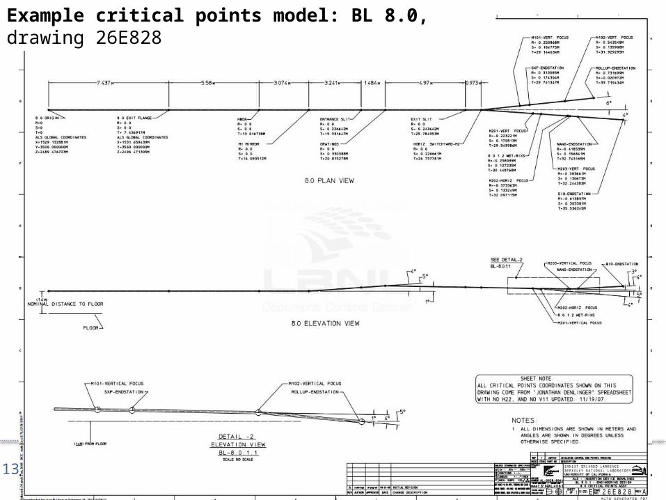
Critical points layout drawing for beamline
• Defined in RST coordinate system• Origin and second point in ALS Global Coordinate System• One coordinate system per beamline• Defines locations (and orientation) of critical beamline
components– Mirrors, monochromators, apertures, slits, diagnostics– Be thoughtful in deciding what should be included in
critical points layout• Drawing will be referenced by Survey and Alignment• File in Document Control Center• Define as early as possible in the design process• Expect changes!
– Undulator source may not be fully defined until late in the beamline design process
Ref: Eng Note M7957
Example drawings:26B90126E82826C52225D26824M51926H348
Critical Points Layouts | March 2014(13)
Example critical points model: BL 8.0, drawing 26E828

Critical Points Layouts | March 2014(14)
Theoretical vs. actual points
• We do all our designs using theoretically ideal points• All CAD models should be at theoretically idealized locations
• Survey and Alignment group determines the difference between theoretically ideal locations and actual locations
– Storage ring is not perfectly circular– Storage ring is not perfectly flat– Storage ring is not perfectly level– Source points deviate from ideal in both location and angle
• Survey and Alignment will install beamline to align to actual source location (“girder-centric”)
– Confirm difference with Survey and Alignment to ensure beamline can accommodate difference between ideal and actual

Critical Points Layouts | March 2014(15)
Ownership of critical points
• During design phase:– Source point locations are developed and owned by the project’s Lead Engineer
for Storage Ring• Typically someone in ALS Magnetics Group• CAD work usually performed by a design associate in ALS Mag Group
– Beamline critical points models and drawings owned by project’s Lead Engineer for Beamline
• Typically someone in ALS Mechanical Eng• CAD work usually performed by a design associate in ALS ME Group
– Beamline scientist and project manager needs to be in the loop– Coordination is critical!
• After installation and commissioning– Beamline scientist owns critical points information
• ALS Mech Eng group provides assistance as needed to update or change critical point models and drawings
• Critical point drawings should NOT reflect actual locations of devices, only theoretical critical point information