CRITICAL EVALUATION OF PROVEN CHEMICAL WEAPON DESTRUCTION TECHNOLOGIES
130
Pure Appl. Chem., Vol. 74, No. 2, pp. 187–316, 2002. © 2002 IUPAC 187 INTERNATIONAL UNION OF PURE AND APPLIED CHEMISTRY ORGANIC AND BIOMOLECULAR CHEMISTRY DIVISION IUPAC COMMITTEE ON CHEMICAL WEAPON DESTRUCTION TECHNOLOGIES* WORKING PARTY ON EVALUATION OF CHEMICAL WEAPON DESTRUCTION TECHNOLOGIES** CRITICAL EVALUATION OF PROVEN CHEMICAL WEAPON DESTRUCTION TECHNOLOGIES (IUPAC Technical Report) Prepared for publication by GRAHAM S. PEARSON 1,‡ AND RICHARD S. MAGEE 2 1 Department of Peace Studies, University of Bradford, Bradford, West Yorkshire BD7 1DP, UK 2 Carmagen Engineering, Inc., 4 West Main Street, Rockaway, NJ 07866, USA *Membership of the IUPAC Committee is: Chairman: Joseph F. Burnett; Members: Wataru Ando (Japan), Irina P. Beletskaya (Russia), Hongmei Deng (China), H. Dupont Durst (USA), Daniel Froment (France), Ralph Leslie (Australia), Ronald G. Manley (UK), Blaine C. McKusick (USA), Marian M. Mikolajczyk (Poland), Giorgio Modena (Italy), Walter Mulbry (USA), Graham S. Pearson (UK), Kurt Schaffner (Germany). **Membership of the Working Group was as follows: Chairman: Graham S. Pearson (UK); Members: Richard S. Magee (USA), Herbert de Bisschop (Belgium). The Working Group wishes to acknowledge the contributions made by the following, although the conclusions and contents of the Technical Report remain the responsibility of the Working Group: Joseph F. Bunnett (USA), Charles Baronian (USA), Ron G. Manley (OPCW), Georgio Modena (Italy), G. P. Moss (UK), George W. Parshall (USA), Julian Perry Robinson (UK), and Volker Starrock (Germany). ‡ Corresponding author Republication or reproduction of this report or its storage and/or dissemination by electronic means is permitted without the need for formal IUPAC permission on condition that an acknowledgment, with full reference to the source, along with use of the copyright symbol ©, the name IUPAC, and the year of publication, are prominently visible. Publication of a translation into another language is subject to the additional condition of prior approval from the relevant IUPAC National Adhering Organization.
Transcript of CRITICAL EVALUATION OF PROVEN CHEMICAL WEAPON DESTRUCTION TECHNOLOGIES

Pure Appl. Chem., Vol. 74, No. 2, pp. 187–316, 2002.© 2002 IUPAC
187
INTERNATIONAL UNION OF PURE AND APPLIED CHEMISTRY
ORGANIC AND BIOMOLECULAR CHEMISTRY DIVISION
IUPAC COMMITTEE ON CHEMICAL WEAPON DESTRUCTION TECHNOLOGIES*
WORKING PARTY ON EVALUATION OF CHEMICAL WEAPON DESTRUCTION TECHNOLOGIES**
CRITICAL EVALUATION OF PROVEN CHEMICALWEAPON DESTRUCTION TECHNOLOGIES
(IUPAC Technical Report)
Prepared for publication byGRAHAM S. PEARSON1,‡ AND RICHARD S. MAGEE2
1Department of Peace Studies, University of Bradford, Bradford, West Yorkshire BD7 1DP, UK2Carmagen Engineering, Inc., 4 West Main Street, Rockaway, NJ 07866, USA
*Membership of the IUPAC Committee is: Chairman: Joseph F. Burnett; Members: Wataru Ando (Japan), Irina P. Beletskaya (Russia), Hongmei Deng(China), H. Dupont Durst (USA), Daniel Froment (France), Ralph Leslie (Australia), Ronald G. Manley (UK),Blaine C. McKusick (USA), Marian M. Mikolajczyk (Poland), Giorgio Modena (Italy), Walter Mulbry (USA),Graham S. Pearson (UK), Kurt Schaffner (Germany).
**Membership of the Working Group was as follows:Chairman: Graham S. Pearson (UK); Members: Richard S. Magee (USA), Herbert de Bisschop (Belgium).
The Working Group wishes to acknowledge the contributions made by the following, although the conclusionsand contents of the Technical Report remain the responsibility of the Working Group: Joseph F. Bunnett (USA),Charles Baronian (USA), Ron G. Manley (OPCW), Georgio Modena (Italy), G. P. Moss (UK), George W. Parshall(USA), Julian Perry Robinson (UK), and Volker Starrock (Germany).
‡Corresponding author
Republication or reproduction of this report or its storage and/or dissemination by electronic means is permitted without theneed for formal IUPAC permission on condition that an acknowledgment, with full reference to the source, along with use of thecopyright symbol ©, the name IUPAC, and the year of publication, are prominently visible. Publication of a translation intoanother language is subject to the additional condition of prior approval from the relevant IUPAC National AdheringOrganization.
Critical evaluation of proven chemical weapon destruction technologies
(IUPAC Technical Report)
Abstract: A critical evaluation is made of the chemical weapon destruction tech-nologies demonstrated for 1 kg or more of agent in order to provide informationabout the technologies proven to destroy chemical weapons to policy-makers andothers concerned with reaching decisions about the destruction of chemicalweapons and agents. As all chemical agents are simply highly toxic chemicals, itis logical to consider the destruction of chemical agents as being no different fromthe consideration of the destruction of other chemicals that can be as highlytoxic—their destruction, as that of any chemicals, requires the taking of appropri-ate precautions to safeguard worker safety, public health, and the environment.The Chemical Weapons Convention that entered into force in 1997 obliges allStates Parties to destroy any stockpiles of chemical weapons within 10 years fromthe entry into force of the Convention—by 2007—with the possibility of an exten-sion for up to 5 years to 2012. There is consequently a tight timeline under thetreaty for the destruction of stockpiled chemical weapons and agents—primarilyheld in Russia and the United States. Abandoned or old chemical weapons—notably in Europe primarily from World War I, in China from World War II as wellas in the United States—also have to be destroyed. During the past 40 years, morethan 20 000 tonnes of agent have been destroyed in a number of countries and over80 % of this has been destroyed by incineration. Although incineration is wellproven and will be used in the United States to destroy over 80 % of the U.S.stockpile of 25 800 tonnes of agent, considerable attention has been paid particu-larly in the United States to alternative technologies to incineration because ofseveral constraints that are specific to the United States. Much of the informationin this report is based on U.S. experience—as the United States had, along with theRussian Federation, by far the largest stockpiles of chemical weapons and agentsanywhere in the world. The United States has made much progress in destroyingits stockpile of chemical weapons and agents and has also done more work thanany other country to examine alternative technologies for the destruction of chem-ical weapons and agents. However, the national decisions to be taken by countriesfaced with the destruction of chemical weapons and agents need to be made in thelight of their particular national conditions and standards—and thus may wellresult in a decision to use different approaches from those adopted by the UnitedStates. This report provides information to enable countries to make their owninformed and appropriate decisions.
G. S. PEARSON AND R. S. MAGEE
© 2002 IUPAC, Pure and Applied Chemistry 74, 187–316
188
CONTENTS
INTRODUCTION 190
I. MANDATE FOR DESTRUCTION 194
II. OVERALL PERSPECTIVE 202A. Experience in the destruction of chemical weapons 202B. Chemical weapons awaiting destruction 207C. Summary 212
III. NATURE OF THE PROBLEM 213
IV. TRANSPORT OF CHEMICAL WEAPONS AND BULK AGENT 216A. Introduction 216B. Experience 216C. Risk perspectives 220
V. REMOVAL OF CHEMICAL AGENTS FROM CHEMICAL WEAPONS 223A Disassembly and draining 223B. Explosive charges for accessing chemical weapons 224C. Water-jet technology for munitions cleaning and cutting 225D. Cryofracture 226
VI. HIGH-TEMPERATURE DESTRUCTION OF CHEMICAL AGENTS 230A. Incineration 230B. Plasma pyrolysis 239C. Molten metal technology 244D. Hydrogenolysis 247E. Destruction of arsenicals 251
VII. LOW-TEMPERATURE DESTRUCTION OF CHEMICAL AGENTS 258A. Hydrolysis of mustard agent HD 258B. Hydrolysis of mustard and nerve agents using aqueous sodium hydroxide 262C. Reaction of mustard and nerve agents using amines and other reagents 265D. Electrochemical oxidation 267E. Solvated electron technology (SET) 272
VIII. EFFLUENT TREATMENT 276A. Gas 276B. Liquid 280C. Solid 289
IX. DEALING WITH OLD RECOVERED MUNITIONS 291A. Transportation of old chemical weapons 294B. Identification 295C. Removal of chemical warfare agents from munitions 295D. Destruction including mobile destruction facilities 297E. Transport of toxic waste 297F. Chemical weapons abandoned by Japan in China 298G. U.S. Army Non-Stockpile Chemical Materiel Project 300
X. TECHNOLOGY COMPARISONS 305
XI. TECHNOLOGIES AND CONSTRAINTS: MAKING INFORMED DECISIONS 309
GLOSSARY OF ACRONYMS 314
© 2002 IUPAC, Pure and Applied Chemistry 74, 187–316
Critical evaluation of proven chemical weapon destruction technologies 189

INTRODUCTION
1. The aim of the IUPAC Working Party on Evaluation of Chemical Weapon DestructionTechnologies has been to provide information about the technologies that have been proven todestroy chemical weapons to policy-makers and others concerned with reaching decisions aboutthe destruction of chemical weapons and agents. The Working Party has recognized that eachcountry faced with destruction of chemical weapons will need to take decisions on how to achievethis by considering both the quantity and nature of the chemical weapons in that country, therequirements of the Chemical Weapons Convention, and its own national laws and regulations indeciding where and how to destroy them safely with minimum impact on public health and theenvironment. Consequently, this report is designed to provide appropriate and relevant informa-tion on the proven available destruction technologies in order to help countries arrive at informednational decisions appropriate for that country.
2. The Working Party has examined the technologies for the destruction of chemical weapons thathave been demonstrated on 1 kg or more of toxic chemical agent. In carrying out this study, theWorking Party has first taken note of the mandate for destruction that stems from the requirementsof the Chemical Weapons Convention (CWC) opened for signature in January 1993, entered intoforce on 29 April 1997 and, in December 2001, has 144 States Parties [1]. The CWC requires thatall declared chemical weapons be destroyed within 10 years after the entry into force of theConvention—in other words, by 29 April 2007—with a possible extension, should that be neces-sary, for up to five years to 29 April 2012. The CWC also sets out requirements for the destruc-tion of old and abandoned chemical weapons [2] that will continue to be found for decades incountries where chemical weapons have been produced, tested, stored, and used. There are thustwo principal categories of chemical weapons:
a. Stockpiled chemical weapons, which have to be destroyed by 29 April 2007 with a possi-ble extension to 29 April 2012; and
b. Old and abandoned chemical weapons, in unknown types and quantities, which will befound from time to time and will need to be destroyed also by 29 April 2007 unless theExecutive Council decides to modify the provisions on the time limit.
3. A historical perspective is then provided giving an indication of the nature of the chemicals thathave been used as chemical weapons during the past century and then addresses the nature of theproblem. Many chemical weapons have been destroyed or disposed of by methods that are nolonger accepted—and indeed, the CWC specifically prohibits dumping in any body of water,land burial, and open pit burning. During the past 40 years, over 20 000 agent-tonnes of chem-ical weapons have been destroyed; more than 80 % by incineration and the remainder by neu-tralization. It should be noted that the unit used in this report for the quantities of chemicalweapons destroyed is agent-tonnes and not the weight of munitions. Following the entry intoforce of the CWC, a total figure has been published by the Organization for the Prohibition ofChemical Weapons (OPCW) for the chemical agents declared and destroyed. The figure as of 30June 2001 for the total declared is 69 862 agent-tonnes, and the total destroyed is 5 734 agent-
G. S. PEARSON AND R. S. MAGEE
© 2002 IUPAC, Pure and Applied Chemistry 74, 187–316
190
1. Available at http://www.opcw.org2. The definitions of these terms in the Chemical Weapons Convention are provided in Chapter I of
this report.

tonnes. The principal contributors to the global stockpile are the United States and the RussianFederation; the United States has declared its stockpile as comprising some 31 495 agent-tons(short tons) [3] which corresponds to 28 570 agent-tonnes whereas the Russian Federation hasdeclared [4] a stockpile of about 40 000 agent-tonnes. As India and one other country (knownfrom non-OPCW information to be South Korea) have also declared chemical weapons, the com-bined stockpiles for these two countries can be deduced as being about 1 500 agent-tonnes. As ofOctober 2001, the United States had destroyed using incineration over 20 % [5] of its stockpiledchemical weapons—or some 6 700 agent-tonnes. In addition to stockpiled chemical weapons,there are also quantities of old and abandoned chemical weapons in several countries around theworld—notably in Europe primarily from World War I, in China from World War II as well as inthe United States—which also need to be destroyed.
4. In considering the technologies for the destruction of chemical weapons, it is important to recog-nize that the destruction technology is only one part of the overall process of safely disposing ofthese unwanted materials. The technology destroys the agents and decontaminates their contain-ers while creating residual process streams (or effluent streams) whether gas, liquid, or solid. Thetreatment of these effluent streams to permit discharge to the environment with minimum impacton public health and the environment is as important as the destruction technology itself. Becausechemical agents were produced to cause harm, there was never any necessity to ensure that theagents produced were particularly pure, as the original considerations were simply that the agentshould be effective and should have sufficient stability to be stored for a number of years prior touse. The destruction and disposal is consequently made more complex because the agent is likelyto contain impurities and materials, such as solvents, which were present when it was originallyproduced, as well as degradation products generated during storage. Many stockpiled chemicalweapons are over 40 years old, and consequently the nature of their contents is variable and uncer-tain. This variation in the material to be destroyed means that the requirement is to identify tech-nologies and effluent treatments that are robust in that they are capable of dealing with the impu-rities and the variations in agent composition.
5. This report first addresses transportation of chemical weapons and bulk agent from storage depotsor other locations where chemical weapons have been found to sites at which they are destroyed.The various options for the removal of the agents from weapons are then considered. The nexttwo chapters examine the high-temperature and low-temperature destruction technologies,respectively, which have been used—or are being considered for use—with chemical agents. Theoptions for gas, liquid, and solid effluent treatment are then addressed. A subsequent chapter con-siders how to deal with abandoned chemical weapons that will be found intermittently inunknown types and quantities in many countries for decades to come. References are provided toassist those seeking additional detail.
© 2002 IUPAC, Pure and Applied Chemistry 74, 187–316
Critical evaluation of proven chemical weapon destruction technologies 191
3. U.S. Department of Defense News Release, U.S. Chemical Weapons Stockpile InformationDeclassified, Reference Number No. 024-96, 22 January 1996. Available athttp://www.defenselink.mil/news/ Jan1996/b12496_bt024-96.htm
4. Government of the Russian Federation, Resolution No. 510 of 5 July 2001, On MakingAmendments and Additions to the Resolution by the Government of the Russian Federation ofMarch 21, 1996 (No. 305) on Approving the Federal Special Program “Chemical WeaponsStockpiles Destruction in the Russian Federation”. Available at http:www.armscontrol.org
5. A. Johnson-Winegar. The U.S. Chemical Demilitarization Program, Statement before the SenateArmed Services Committee, Sub-Committee on Emerging Threats and Capabilities, U.S. Senate,12 July 2001.

6. A final chapter considers the technologies and constraints that have to be considered by a coun-try faced with making informed decisions about destruction of chemical weapons. The WorkingParty is acutely aware that much of the information presented in this report is based on U.S. expe-rience [6], and one of us (Richard S. Magee) had been Chairman of the U.S. National ResearchCouncil 1996 Panel on “Review and Evaluation of Alternative Chemical Disposal Technologies”.However, this is hardly surprising as the United States had, along with the Russian Federation, byfar the largest stockpiles of chemical weapons and agents anywhere in the world. The UnitedStates has made much progress in destroying its stockpile of chemical weapons and agents andhas also done more work than any other country to examine alternative technologies for thedestruction of chemical weapons and agents. This report therefore draws heavily on the U.S.experience. However, the national decisions to be taken by countries faced with the destruc-tion of chemical weapons and agents need to be made in the light of their particular nationalconditions and standards—and thus may well result in a decision to use differentapproaches from those adopted by the United States. National decisions in other countrieswill need to consider the stockpile size and the nature of the chemical weapons in those countriesin deciding both where and how to destroy them in accordance with the requirements of theChemical Weapons Convention and to do this safely with minimum impact on public health andthe environment. The aim of this report is to provide information on the available destructiontechnologies in order to help countries arrive at informed national decisions appropriate for thatcountry.
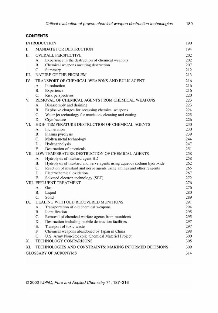
7. In order to maximize the benefits of the report in helping countries arrive at informed nationaldecisions appropriate for that country in respect of chemical weapons destruction technology, thisreport uses the commonly used terminology for chemical warfare (CW) agents and provides atabulation here to relate these common terms for CW agents to their IUPAC chemical names.
G. S. PEARSON AND R. S. MAGEE
© 2002 IUPAC, Pure and Applied Chemistry 74, 187–316
192
6. Indeed, it should be noted that because one of us (Richard S. Magee) had been Chairman of theU.S. National Research Council 1996 Panel on “Review and Evaluation of Alternative ChemicalDisposal Technologies”, language used in that NRC Report has been reviewed, updated, andmodified where appropriate—or left unchanged where appropriate.
CW agent IUPAC name Alternative names
AC hydrogen cyanideAdamsite 10-chloro-5,10-dihydrophenarsazine DMBBC 2-bromo-2-phenylacetonitrile CA; α-bromobenzylcyanide;
1-bromo-1-tolunitrileBZ 3-quinuclidinyl benzilate 3-quinuclidinyl benzilateCA 2-bromo-2-phenylacetonitrile BBC; α-bromobenzylcyanide;
1-bromo-1-tolunitrileCS (2-chlorobenzylidene)malonodinitrileCG phosgene carbonyl dichlorideCK cyanogen chlorideClark I chlorodiphenylarsine DA; diphenylchloroarsine;Clark II cyanodiphenylarsine DC; diphenylcyanoarsine;
diphenylarsinous cyanideCN α-chloroacetophenone 1-chloroacetophenone;
2-chloro-1-phenylethan-1-oneDA diphenyarsinous chloride Clark I; diphenylchloroarsineDC cyanodiphenylarsine Clark II; diphenylcyanoarsineDM 10-chloro-5,10-dihydrophenarsazine AdamsiteGA O-ethyl N,N-dimethyl tabun
phosphoroamidocyanidateGB O-isopropyl methylphosphonofluoridate sarinGD O-pinacolyl methylphosphonofluoridate soman; 3,3-dimethylbutan-2-yl
methylphosphonofluoridate;O-(1,2,2-trimethylpropyl)-methylphosphonofluoridate
H bis(2-chloroethyl) sulfide mustard; sulfur mustard;bis(2-chloroethyl) sulfane
HN-3 tris(2-chloroethyl) amine nitrogen mustardLewisite 2-chlorovinyldichlorarsine L; 2-chloroethenylarsonous dichloride;
2-chlorovinylarsinous dichlorideNitrogen mustard substituted (2-chloroethyl) amines HN-1, HN-2, HN-3Sarin O-isopropyl methylphosphonofluoridate GBSoman O-pinacolyl methylphosphonofluoridate GD; 3,3-dimethylbutan-2-yl
methylphosphonofluoridate;O-(1,2,2-trimethylpropyl)-methylphosphonofluoridate
Tabun O-ethyl N,N-dimethyl GA;phosphoroamidocyanidate
VX O-ethyl S-2-diisopropylaminoethyl O-ethyl S-2-diisopropylaminoethylmethyl phosphonothiolate methyl phosphonothioate
VR O-isobutyl S-[2-diethylamino ethyl] Russian VX; methyl thiophosphonate O-isobutyl S-[2-diethylamino
ethyl] methyl phosphothioate
© 2002 IUPAC, Pure and Applied Chemistry 74, 187–316
Critical evaluation of proven chemical weapon destruction technologies 193
I. MANDATE FOR DESTRUCTION
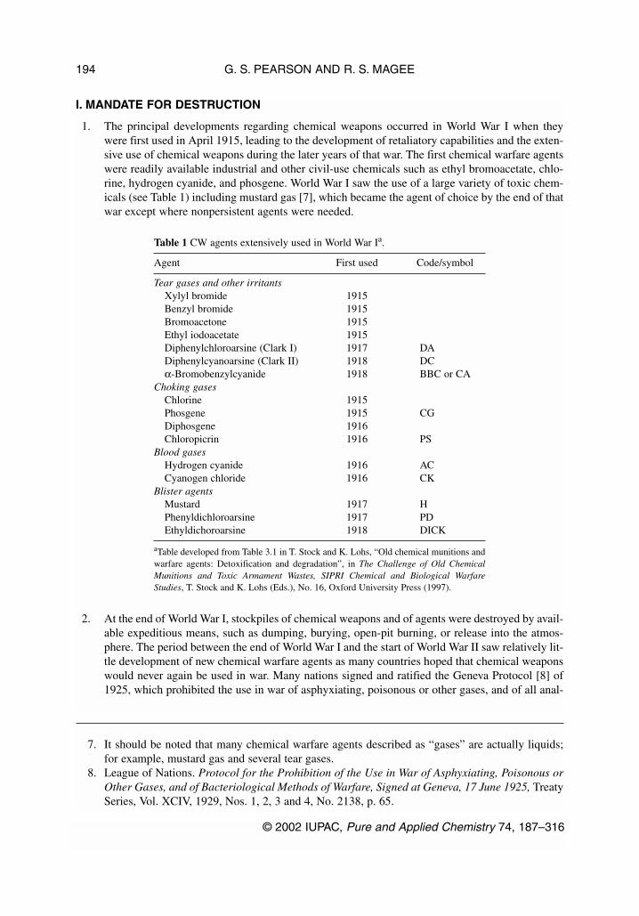
1. The principal developments regarding chemical weapons occurred in World War I when theywere first used in April 1915, leading to the development of retaliatory capabilities and the exten-sive use of chemical weapons during the later years of that war. The first chemical warfare agentswere readily available industrial and other civil-use chemicals such as ethyl bromoacetate, chlo-rine, hydrogen cyanide, and phosgene. World War I saw the use of a large variety of toxic chem-icals (see Table 1) including mustard gas [7], which became the agent of choice by the end of thatwar except where nonpersistent agents were needed.
Table 1 CW agents extensively used in World War Ia.
Agent First used Code/symbol
Tear gases and other irritantsXylyl bromide 1915Benzyl bromide 1915Bromoacetone 1915Ethyl iodoacetate 1915Diphenylchloroarsine (Clark I) 1917 DADiphenylcyanoarsine (Clark II) 1918 DCα-Bromobenzylcyanide 1918 BBC or CA
Choking gasesChlorine 1915Phosgene 1915 CGDiphosgene 1916Chloropicrin 1916 PS
Blood gasesHydrogen cyanide 1916 ACCyanogen chloride 1916 CK
Blister agentsMustard 1917 HPhenyldichloroarsine 1917 PDEthyldichoroarsine 1918 DICK
aTable developed from Table 3.1 in T. Stock and K. Lohs, “Old chemical munitions andwarfare agents: Detoxification and degradation”, in The Challenge of Old ChemicalMunitions and Toxic Armament Wastes, SIPRI Chemical and Biological WarfareStudies, T. Stock and K. Lohs (Eds.), No. 16, Oxford University Press (1997).
2. At the end of World War I, stockpiles of chemical weapons and of agents were destroyed by avail-able expeditious means, such as dumping, burying, open-pit burning, or release into the atmos-phere. The period between the end of World War I and the start of World War II saw relatively lit-tle development of new chemical warfare agents as many countries hoped that chemical weaponswould never again be used in war. Many nations signed and ratified the Geneva Protocol [8] of1925, which prohibited the use in war of asphyxiating, poisonous or other gases, and of all anal-
G. S. PEARSON AND R. S. MAGEE
© 2002 IUPAC, Pure and Applied Chemistry 74, 187–316
194
7. It should be noted that many chemical warfare agents described as “gases” are actually liquids;for example, mustard gas and several tear gases.
8. League of Nations. Protocol for the Prohibition of the Use in War of Asphyxiating, Poisonous orOther Gases, and of Bacteriological Methods of Warfare, Signed at Geneva, 17 June 1925, TreatySeries, Vol. XCIV, 1929, Nos. 1, 2, 3 and 4, No. 2138, p. 65.

ogous liquids materials or devices. Some States, however, signed with reservations that wouldallow States to retaliate in kind with chemical (or biological) weapons should these be usedagainst the State.
3. World War II saw a major concern that chemical weapons might be used, and both sides acquiredstocks of chemical weapons. In addition, Germany developed a new class of chemical agent basedon toxic organophosphorus compounds known as the G nerve agents. Although both sides hadlarge stocks of weapons and agents (see Table 2), chemical weapons were not used in World WarII apart from by Japan, and the end of the war saw the discovery by the Allied Forces of theGerman nerve agents, which were then studied extensively in the post-war years, resulting in theidentification of a further class of even more toxic agents—the V nerve agents. It should, how-ever, be noted that these nerve agents were not found by scientists in military laboratories seek-ing more effective chemical warfare agents, but were discovered by scientists engaged in indus-trial chemistry.
Table 2 CW agents stockpiled in World War II [8].
Agent Code/symbol
Tear gases and other irritantsEthyl iodoacetateDiphenylchloroarsine (Clark I) DADiphenylcyanoarsine (Clark II) DCα-Bromobenzylcyanide CAAdamsite DM1-Chloroacetophenone CN
Choking gasesPhosgene CGDiphosgeneChloropicrin PS
Blood gasesHydrogen cyanide ACCyanogen chloride CK
Blister agentsMustard HPhenyldichloroarsineLewisite LBis(2-chloroethylthioethyl)etherTris(2-chloroethyl)amine HN-3
Nerve agentsTabun GA
Most of the national stockpiles of weapons and agents were abandoned or destroyed at the end ofWorld War II. Such abandoned chemical weapons are discovered from time to time in a numberof countries and need to be destroyed safely.
4. Following World War II and the recognition of the potential role for nuclear weapons, a numberof countries in the 1950s and the 1960s decided to abandon their offensive chemical warfare pro-grams. Consequently, by the latter years of the 1960s, proposals were being made in Geneva foran international treaty that would prohibit the development, production, acquisition, and storageof chemical weapons. It was to take some 20 years for these negotiations to be brought to a suc-cessful conclusion with the opening for signature on 13–15 January 1993 of the ChemicalWeapons Convention, which entered into force on 29 April 1997.
© 2002 IUPAC, Pure and Applied Chemistry 74, 187–316
Critical evaluation of proven chemical weapon destruction technologies 195

5. The Chemical Weapons Convention totally prohibits the development, production, transfer,acquisition, stockpiling, and retention of chemical weapons and their use and requires all StatesParties to undertake “to destroy chemical weapons it owns or possesses, or that are located in anyplace under its jurisdiction or control, in accordance with the provisions of this Convention” [9].The scope of the Convention is broad in that chemical weapons are defined as being:
Toxic chemicals and their precursors, except where intended for purposes not prohibitedunder the Convention, as long as the types and quantities are consistent with such purposes[10]
and toxic chemicals are defined as
Any chemical which through its chemical action on life processes can cause death, tempo-rary incapacitation or permanent harm to humans or animals. This includes all such chem-icals, regardless of their origin or of their method of production, and regardless of whetherthey are produced in facilities, in munitions or elsewhere. [11]
It is thus evident that all chemicals are covered by the prohibition of the Convention unless theyare intended for purposes not prohibited under the Convention and are in types and quantities thatare consistent with such purposes.
6. The requirement for the destruction of chemical weapons is detailed in Article IV of theConvention, which requires that:
Each State Party shall destroy all chemical weapons.... Such destruction shall begin notlater than two years after this Convention enters into force for it and shall finish not laterthan 10 years after entry into force of this Convention. [12]
The destruction requirements are further elaborated in Part IV(A) of the Verification Annex,which inter alia require that the “chemicals are converted in an essentially irreversible way to aform unsuitable for production of chemical weapons, and which in an irreversible manner ren-ders munitions and other devices unusable as such.” [13]
7. In addition, Part IV(A) sets out provisions for the order of destruction of chemical weapons,which is based on the obligations specified in Article I and the other Articles of the Convention.Paragraph 16 of Part IV (A) states that:
16. For the purpose of destruction, chemical weapons declared by each State Party shall bedivided into three categories:
G. S. PEARSON AND R. S. MAGEE
© 2002 IUPAC, Pure and Applied Chemistry 74, 187–316
196
9. Organization for the Prohibition of Chemical Weapons. Convention on the Prohibition of theDevelopment, Production, Stockpiling and Use of Chemical Weapons and on their Destruction,Article I, para. 2. Available at http://www.opcw.org
10. CWC, Article II, para. 1.11. CWC, Article II, para. 2.12. CWC, Article IV, para. 6.13. CWC, Verification Annex, Part IV (A), para. 12.

Category 1: Chemical weapons on the basis of Schedule 1 chemicals and their partsand components;
Category 2: Chemical weapons on the basis of all other chemicals and their parts andcomponents;
Category 3: Unfilled munitions and devices, and equipment specifically designed foruse directly in connection with the employment of chemical weapons.
8. Paragraph 17 of Part IV (A) sets out the requirements placed on the State Party for the destruc-tion of chemical weapons in the three categories:
Category Start of destruction Completion of destruction
1 Not later than 2 years after EIF Not later than 10 years after EIF for the State Party of the Convention
2 Not later than 1 year after EIF Not later than 5 years after EIF for the State Party of the Convention
3 Not later than 1 year after EIF Not later than 5 years after EIF for the State Party of the Convention
EIF = entry into force
It will be noted that the requirement is the more demanding the later that the Convention entersinto force for a particular State Party as the completion deadlines are after the entry into force ofthe Convention (i.e., 29 April 1997).
9. Specific requirements are also specified for the amounts of Category 1 chemical weapons to bedestroyed again as a function of time after the entry into force of the Convention:
Phase Amount to be destroyed Time by which to be destroyed
1 Not less than 1 % Not later than 3 years after EIFof the Convention
2 Not less than 20 % Not later than 5 years after EIFof the Convention
3 Not less than 45 % Not later than 7 years after EIFof the Convention
4 All Category 1 Not later than 10 years after EIFchemical weapons of the Convention
10. The Verification Annex also includes a provision allowing a State Party, if it believes that it willbe unable to ensure destruction of all chemical weapons within the 10-year time frame, to applyto the Executive Council for an extension of the deadline for the completing the destruction of itschemical weapons [14]. The Convention, however, states that “any extension shall be the mini-mum necessary but in no case shall the deadline for a State Party to complete its destruction ofall chemical weapons be extended beyond 15 years after entry into force of this Convention.” [15]
© 2002 IUPAC, Pure and Applied Chemistry 74, 187–316
Critical evaluation of proven chemical weapon destruction technologies 197
14. CWC, Verification Annex, Part IV (A), para. 24.15. CWC, Verification Annex, Part IV (A), para. 26.

11. An exception is made in respect of “old chemical weapons and abandoned chemical weapons”,which are defined in the Convention as:
“Old Chemical Weapons” means:
(a) Chemical weapons which were produced before 1925; or
(b) Chemical weapons produced in the period between 1925 and 1946 that have deteri-orated to such an extent that they can no longer be used as chemical weapons.
“Abandoned Chemical Weapons” means:
Chemical weapons, including old chemical weapons, abandoned by a State after 1 January1925 on the territory of another State without the consent of the latter. [16]
12. Part IV (B) of the Verification Annex sets out the requirements for the destruction of both old andabandoned chemical weapons. In respect of old chemical weapons produced before 1925 the sig-nificant requirement is that
6. A State Party shall treat old chemical weapons that have been confirmed by the TechnicalSecretariat as meeting the definition in Article II, paragraph 5 (a), as toxic waste. It shallinform the Technical Secretariat of the steps being taken to destroy or otherwise dispose ofsuch old chemical weapons as toxic waste in accordance with its national legislation. [17]
The logic in regarding these particular old chemical weapons as toxic waste will be apparentwhen it is recalled that the wide range of toxic chemicals used in World War I (see Table 1) weregenerally available toxic chemicals or industrial chemicals, that could be readily chlorinated,which were used as chemical weapons and were not made expressly for this purpose.
13. In regard to old chemical weapons produced between 1925 and 1946, the principal considerationis whether or not they can still be used as chemical weapons. If the Technical Secretariat confirmsthat they meet the definition in Article II, paragraph 5(b)—namely that they have deterioratedto such an extent that they can no longer be used as chemical weapons—then the requirementin the CWC is that
7. ...a State Party shall destroy old chemical weapons that have been confirmed by theTechnical Secretariat as meeting the definition in Article II, paragraph 5 (b), in accordancewith Article IV and Part IV (A) of this Annex. Upon the request of the State Party, theExecutive Council may, however, modify the provisions on time-limit and order of destruc-tion of these old chemical weapons, if it determines that doing so would not pose a risk tothe object and purpose of this Convention. The request shall contain specific proposals formodification of the provisions and a detailed explanation of the reasons for the proposedmodifications.
Other chemical weapons produced between 1925 and 1946 that do not meet the definition inArticle II, paragraph 5(b) shall be destroyed in the same way as chemical weapons produced from1 January 1946 onwards—in accordance with Article IV and Annex IV (A) of the VerificationAnnex.
G. S. PEARSON AND R. S. MAGEE
© 2002 IUPAC, Pure and Applied Chemistry 74, 187–316
198
16. CWC, Article II, paras. 5 and 6.17. CWC, Verification Annex, Part IV (B), para. 6.

14. For abandoned chemical weapons, the requirement is that these be destroyed. These will betreated in the same way as declared chemical weapons—in accordance with Article IV and AnnexIV (A) of the Verification Annex—unless the abandoned chemical weapons also meet the defini-tion of old chemical weapons in Article II 5(b) when the Executive Council of the CWC mayagree to modify or in exceptional cases suspend the provisions for destruction so long as doingso “would not pose a risk to the object and purpose of this Convention” [18]. Should the aban-doned chemical weapons not meet the definition of old chemical weapons in Article II 5(b) thenthe Executive Council may, on the request of the State Party on whose territory these weaponshave been abandoned, in exceptional circumstances modify the provisions on the time limit andthe order of destruction, if the Executive Council determines that doing so would not pose a riskto the object and purpose of the Convention.
15. Consequently, under the CWC there are essentially two principal categories of chemical weapons:
a. Those declared by States Parties that are essentially chemical weapons or chemical warfareagents in the stockpile of that State, and that have to be destroyed during the period com-mencing two years after entry into force of the CWC for that State and being completed notlater than 10 years after entry into force of the CWC (i.e., by 29 April 2007).
b. Old chemical weapons that have been produced before 1925, which shall be destroyed astoxic waste.
16. Abandoned chemical weapons form an intermediate group, which may be destroyed in the sameway as stockpiled chemical weapons or possibly, with the agreement of the Executive Council,destroyed in the same way as old chemical weapons, as toxic waste. In effect, chemical weaponsare either stockpile munitions or agents that are still in storage or non-stockpile munitions oragent that have been buried often on battlefields, on present and past military bases, along trans-portation routes or dumped at sea. Such non-stockpile munitions or agents may also fall into thecategories of old chemical weapons or abandoned chemical weapons. Insofar as non-stockpilemunitions or agent are concerned, Article IV of the CWC also states that:
17. The provisions of this Article and the relevant provisions of Part IV of the VerificationAnnex shall not, at the discretion of a State Party, apply to chemical weapons buried on itsterritory, before 1 January 1977 and which remain buried, or which had been dumped atsea before 1 January 1985.
Consequently, there is no requirement for States Parties to recover such buried or dumped chem-ical weapons, but should a State party decide to recover them, then they have to be destroyed inaccordance with the requirements specified in the CWC.
17. There is, therefore, a clear incentive for States to destroy their stockpiled chemical weapons in atimely way in order to meet the CWC requirements as well as to remove the hazard associatedwith stockpiled chemical weapons and chemical warfare agents that are gradually aging. Theoverall hazard associated with stockpiled chemical weapons and agents is greater than that asso-ciated with destruction of these weapons and agents. Consequently, taking no action is not aresponsible option. There are no benefits from delaying action to destroy chemical weapons andchemical warfare agents.
18. The time constraints imposed by the CWC—namely, the need to start destroying stockpiledchemical weapons within two years after entry into force of the CWC for that State and com-
© 2002 IUPAC, Pure and Applied Chemistry 74, 187–316
Critical evaluation of proven chemical weapon destruction technologies 199
18. CWC, Verification Annex, Part IV (B), para. 17.
pleting the destruction no later than 29 April 2007—means that it is only practicable to considerdestruction technologies that are mature and have already been proven to be effective in destroy-ing chemical agents. Although there is the possibility that the Executive Council may accept arequest to modify the provisions on the time limit, the basic requirement in the Convention is thatsuch old or abandoned chemical weapons shall be destroyed before 29 April 2007. It is, however,equally true that old or abandoned chemical weapons may well continue to be found for manyyears in States in which chemical weapons have been used or stockpiled, the acceptability ofmature destruction technologies—and hence the possible need for new technologies for destroy-ing these old and abandoned chemical weapons—will depend on what the environmentalrequirements for that State are in regard to gas, liquid, or solid materials released from the wastedisposal process. Such environmental standards are likely to be increasingly more stringentregardless of what is being destroyed.
19. States Parties that have declared chemical weapons under the CWC are also required to meetadditional requirements. Once a State Party has declared its chemical weapons it shall notremove any of these chemical weapons except to a chemical weapons destruction facility[19]. It is also required to submit a general plan for the destruction of chemical weapons provid-ing an overview of the entire national chemical weapon destruction program of the State Party.The Verification Annex specifies [20] that:
Each State Party shall ensure that its chemical weapons destruction facilities are con-structed and operated in a manner to ensure the destruction of the chemical weapons; andthat the destruction process can be verified under the provisions of this Convention.[Emphasis added]
20. The State Party is required to provide detailed information for each destruction facility including [21]:
(d) Detailed technical descriptions, including design drawings and instrument specifica-tions, for the equipment required for: removing the chemical fill from the munitions,devices, and containers; temporarily storing the drained chemical fill; destroying thechemical agent; and destroying the munitions, devices, and containers;
(e) Detailed technical descriptions of the destruction process, including material flowrates, temperatures and pressures, and designed destruction efficiency;
(h) A detailed technical description of measures to facilitate inspections in accordancewith this Convention;
(l) Suggested measures for international verification. [Emphasis added]
21. This detailed information is then reviewed by the Technical Secretariat so that [22]:
35. After a review of the detailed facility information for each destruction facility, theTechnical Secretariat, if the need arises, shall enter into consultation with the State Party
G. S. PEARSON AND R. S. MAGEE
© 2002 IUPAC, Pure and Applied Chemistry 74, 187–316
200
19. CWC, Article IV, para. 4.20. CWC, Verification Annex, Part IV (A), para. 14.21. CWC, Verification Annex, Part IV (A), para. 31.22. CWC, Verification Annex, Part IV (A), para. 35.
concerned in order to ensure that its chemical weapons destruction facilities are designedto assure the destruction of chemical weapons, to allow advanced planning on how verifi-cation measures may be applied and to ensure that the application of verification meas-ures is consistent with proper facility operation, and that the facility operation allowsappropriate verification [Emphasis added].
22. A State Party is therefore required to consult the OPCW about the proposed chemical weaponsdestruction facility so as to ensure that (1) the destruction technology meets the requirement [23]of the CWC that the chemical agents are converted in an essentially irreversible way to a formunsuitable for the production of chemical weapons, and which in an irreversible mannerrenders munitions and other devices unusable as such and (2) the operation of the destructionfacility complies with the CWC requirements for verification of the destruction of chemicalweapons.
23. The IUPAC Working Party on Chemical Weapon Destruction Technologies has consequently lim-ited its consideration in this report to those technologies that are known to have been used todestroy 1 kg or more of an actual chemical agent and appear to have the potential to be usedto destroy ton quantities in the time scales required by the Convention.
© 2002 IUPAC, Pure and Applied Chemistry 74, 187–316
Critical evaluation of proven chemical weapon destruction technologies 201
23. CWC, Verification Annex, Part IV (A), para. 12.

II. OVERALL PERSPECTIVE
1. It is important to set the problem of the destruction of chemical weapons into an overall perspec-tive, which considers both what can be learned from the recent historical record about the destruc-tion of chemical weapons as well as what quantity of chemical weapons remain to be destroyed.
A. Experience in the destruction of chemical weapons
2. The 20th century has seen the use and destruction of vast amounts of chemical weapons. It is clearthat following World War I and again following World War II large numbers of stockpiledweapons and significant quantities of bulk agent were disposed of or destroyed by methods thatwere acceptable at that time but are no longer acceptable today. For example, volatile or gaseouschemicals such as phosgene would be released into the atmosphere, and large quantities of chem-ical agents were disposed of by open-pit burning. Other methods included the dumping of chem-ical weapons into the sea, frequently by loading ships with unwanted weapons and then scuttlingthe ships at sea. In 1972, the Oslo Convention for the Prevention of Marine Pollution by Dumpingof Wastes and Other Matter, dated 29 December 1972 and amended on 12 October 1978 and 1December 1980, prohibited sea dumping [24]. Another common method of disposal was to dis-pose of unwanted chemical weapons by digging trenches and burying the munitions; such land-buried munitions are increasingly being unexpectedly found during building works and excava-tions, particularly in States in which chemical weapons were used or stockpiled. The CWC makesit clear that its provisions in Part IV of the Verification Annex, relating to the destruction of chem-ical weapons, “shall not, at the discretion of a State Party, apply to chemical weapons buried onits territory before 1 January 1977 and which remain buried, or which have been dumped at seabefore 1 January 1985.” [25] The CWC states that it is up to each State Party to “determine howit shall destroy chemical weapons, except that the following processes may not be used: dump-ing in any body of water, land burial or open pit burning…” [Emphasis added] [26]
3. In contrast to the previously favored methods of burial or ocean dumping which had been used todispose of large quantities of chemical weapons, the past three or four decades have seen thedestruction of significant quantities of chemical weapons using more environmentally conscious
G. S. PEARSON AND R. S. MAGEE
© 2002 IUPAC, Pure and Applied Chemistry 74, 187–316
202
24. Oslo Convention for the Prevention of Marine Pollution by Dumping of Wastes and Other Matter,dated 29 December 1972 and amended on 12 October 1978 and 1 December 1980. Available athttp://sedac.ciesin.org/entri/texts/marine.pollution.dumping.of.wastes.1972.html
25. CWC, Article III, para. 2.26. CWC Verification Annex, Part IV (A), para. 13.

destruction methods. Table 3 is based on a summary [27,28] published in 1997 of experience dur-ing the 35 years from 1958 to 1993, which shows that some 14 500 tonnes of mustard and nerveagents have been destroyed either by incineration (I), neutralization (N), or a combination of thesetwo techniques (N/I).
Table 3 Destruction of chemical warfare agents, 1958–1993.
Site Agent Amounta Method Date
Rocky Mountain Arsenal, USA H 2786 tonnes I 1969–74Rocky Mountain Arsenal, USA GB 3799 tonnes N 1973–76Tooele (CAMDS)b, USA GB 34.5 tonnes I 1981–86JACADSc Johnston Atoll, USA—OVT GB 36 tonnes I 1991(operational verification test) data
Tooele (CAMDS), USA VX 7 tonnes I 1984JACADS Johnston Atoll, USA—OVT data VX 49 tonnes I 1992JACADS Johnston Atoll, USA—OVT data HD 51 tonnes I 1992DRES Canada H 700 tonnes N/I 1974–76DRES Canada H 12 tonnes I 1990–91DRES Canada VX, GA, GB 0.3 tonnes N/I 1990–91DRES Canada L 1.5 tonne NMunster, Germany H, etc. 70 tonnes/yr I 1980–Shikhany, Russia GB, GD, H 300 tonnes N/I 1980–90Shikhany, Russia VR 30 tonnes N/I 1980–90
(Russian VX)Porton Down, UK H 20 tonnes I 1970Nancekuke, UK GB 20 tonnes N 1967–68Runcorn, UK H 6000 tonnes I 1958–60Iraq (UNSCOM supervised) H 500 tonnes I 1992–93Iraq (UNSCOM supervised) GA 30 tonnes N 1992–93Iraq (UNSCOM supervised) GB, GB/GF 70 tonnes N 1992–93
aU.S. figures in short tons (2000 lb) converted to tonnes (1000 kg).bCAMDS was a Chemical Agent Munitions Disposal System experimental facility at the Tooele Army Depot, Utah.cThis JACADS data is OVT (Operation Verification Test) data obtained prior to the full-scale operation of the Johnston AtollChemical Agent Disposal System.
© 2002 IUPAC, Pure and Applied Chemistry 74, 187–316
Critical evaluation of proven chemical weapon destruction technologies 203
27. R. G. Sutherland. “The destruction of old and obsolete chemical weapons: Past experience”, inThe Challenge of Old Chemical Munitions and Toxic Armament Wastes, T. Stock and K. Lohs(Eds.), SIPRI Chemical and Biological Warfare Studies, No. 16, p. 141, Oxford University Press(1997); National Research Council, Committee on Alternative Chemical DemilitarizationTechnologies. Alternative Technologies for the Destruction of Chemical Agents and Munitions,Chap. 3, pp. 54–74, National Academy Press, Washington, DC (1993).
28. This summary does not include any information on destruction of chemical weapons by France.It is, however, evident that France has been considering techniques for the destruction of chemi-cal weapons from Frederic Guir, “The technical challenge of dismantling and destroying old andabandoned chemical weapons”, in The Challenge of Old Chemical Munitions and ToxicArmament Wastes, T. Stock and K. Lohs (Eds.), SIPRI Chemical and Biological Warfare Studies,No. 16, p. 156, Oxford University Press (1997) and from a study of a firing pool technique for thedestruction of chemical weapons available as M. Herve Bizeau, “Preliminary technical study fora destruction process”, in Defence Research Establishment Suffield, Reports Presented to theSpecialists Meeting on Chemical Weapons Destruction, Geneva, Switzerland, 7–11 October1991, Suffield Special Publication No. 152, December 1991.

Analysis of this data shows that some 66 % (9600 tonnes) of the 14 500 tonnes was destroyed byincineration, 27 % (3900 tonnes) by neutralization, and 7 % (1000 tonnes) by neutralization/incineration.
4. Incineration is an inherently attractive approach for destruction of organic compounds as the car-bon and hydrogen in the organic compound in the presence of oxygen produce carbon dioxideand water; in addition, the other elements in chemical warfare agents will produce products suchas hydrogen chloride (mustard), sulfur dioxide (mustard), phosphorus pentoxide (nerve agentssuch as GA, GB, VR and VX), hydrogen fluoride (nerve agent GB) and nitrogen dioxide (nerveagents GA, VR and VX). Indeed, chemical warfare agents are combustible and therefore lendthemselves to destruction by incineration. The incineration products are far less toxic than theoriginal chemical warfare agents. Further, the exhaust gases are typically scrubbed by passingthem through countercurrent liquid absorption beds to reduce the level of pollution in the gasesreleased to the atmosphere to an acceptable level that protects public health and the environment.However, organic compounds containing arsenic present additional problems, as many inorganicarsenicals are confirmed carcinogens.
5. Neutralization involves the reaction of the agent, such as the nerve agent GB, with sodiumhydroxide causing the nerve agent GB to hydrolyze, producing as initial products, hydrogen flu-oride and iso-propylmethyl-phosphonic acid (2-propyl methyl phosphonic acid); these both reactwith additional sodium hydroxide to produce the salts, sodium fluoride, and sodium methylphos-phonate. The principal disadvantage of the alkaline hydrolysis of nerve agents is the large volumeof hydrolysate produced, which can typically result in a five-fold increase in the overall volume.Table 4 provides a summary of information on destruction of chemical agents by neutralizationduring the period 1953 to 1993.
Table 4 Destruction of chemical warfare agents by neutralization, 1958–1993.
Country Agent Quantity Reactant Temperature Disposal(tonnes)
United States GB 3799 Aq NaOH Ambient Hazardouslandfill
Canada H 700 Calcium hydroxide 95 Incineration(lime)
Russia GA, GB, H 300 Monoethanolamine 100 IncinerationRussia VR 30 Phosphoric acid and 140 Incineration
(Russian VX) ethylene glycolUnited Kingdom GB 20 20 % NaOH Ambient Discharge
to seaIraq GA 30 Aq NaOH Ambient Discharge
to limed pitIraq GB, GF 70 Aq NaOH Ambient Discharge
to limed pit
The hydrolysate requires further treatment such as biodegradation, supercritical water oxidation,or incineration prior to release to the environment. Other chemical warfare agents, such as mus-tard H, can be neutralized by different processes such as reaction with hot water. However, with-out exception, the resulting hydrolysate requires further treatment to meet current acceptableenvironmental release standards.
G. S. PEARSON AND R. S. MAGEE
© 2002 IUPAC, Pure and Applied Chemistry 74, 187–316
204

6. Further insight into the use of incineration and neutralization to destroy chemical weapons can begained from the ongoing U.S. program to destroy the U.S. chemical weapon and agent stockpilesummarized in Table 5.
Table 5 Schedule for and current status of destruction of U.S. stockpiled chemical munitions (as of October2001)a.
Site Agent % U.S. Stockpile nature Technology Full-scale(short tons) stockpile destruction
Aberdeen 1625 tons 5.2 % HD containers Neutralization 2005–2006Anniston 2254 tons 7.2 % HD, HT, GB, VX Incineration 2002–
munitions HD containers
Blue Grass 523 tons 1.7 % H, GB, VX On holdmunitions
Johnston Atoll 2030 tons 6.4 % HD, GB, VX Incineration 1989–2000munitions & containers Completed
Newport 1269 tons 4.0 % VX containers Neutralization 2004Pine Bluff 3850 tons 12.2 % HD, HT containers Incineration 2003–
GB, VX munitionsPueblo 2611 tons 8.3 % HD, HT munitions On holdb
Tooele 13 616 tons 43.2 % HD, L, GA, GB, VX Incineration 1996–containers 39.4 % destroyed
H, HD, HT, GB, VXmunitions
Umatilla 3717 tons 11.8 % HD containers Incineration 2002GB, VX munitions
Total, 31 495 100 % 23.5 % destroyedagent-tons
Total, 28 572agent-tonnes
aThis is based on stockpile information available at http://www.defenselink.mil/news/Jan1996/ b012496_bt024-96.html andinformation on destruction schedules at individual storage sites available at http://www-pmcd.apgea.army.mil/bTechnology decision expected late 2001.
It is thus evident that over 23.5 % of the U.S. stockpile has already been destroyed. Overall,80.8 % is to be destroyed by incineration, 9.2 % planned to be destroyed by neutralizationand 10 % is currently on hold.
7. On 29 November 2000, the Johnston Atoll Chemical Agent Disposal System (JACADS) hadcompleted destruction of its stockpile of 2031 agent-tons (1843 agent-tonnes) of chemical muni-tions involving the destruction of more than 400 000 rockets, projectiles, mortars, ton containersof agent, and land mines containing mustard and nerve agent (GB and VX) [29]. As of 3 October2001, the Tooele Chemical Agent Disposal Facility (TOCDF) had completed destruction of 5365agent-tons (4867 agent-tonnes) of agent involving the destruction of more than 600 000 rockets,
© 2002 IUPAC, Pure and Applied Chemistry 74, 187–316
Critical evaluation of proven chemical weapon destruction technologies 205
29. Office of the Secretary of Defense (Public Affairs). Chemical Weapons Destruction Complete onJohnston Atoll, News Release, 30 November 2000. Available at http://www.defenselink.mil/news/Nov2000/ b11302000_bt715-00.html

projectiles, bombs, and ton containers [30]. At both facilities, the agents were destroyed by incin-eration. Taken together, the agent destroyed at these two facilities represents a total of some 7396agent-tons (6710 agent-tonnes) and about 23.5 % of the U.S. stockpile of over 31 000 agent-tons(28 000 agent-tonnes). In addition, Table 5 shows that over 80 % of the U.S. stockpile of chemi-cal weapons and agents are to be destroyed by incineration.
8. Much attention has also been paid in the United States to alternative technologies. The initial U.S.approach was to destroy the stockpile by incineration with facilities initially being constructed atJohnston Island in the Pacific Ocean and then at Tooele, Utah. In the early 1990s, there wasincreased public concern in the United States about the possible dangers from emissions fromcommercial waste incineration facilities as well as from military incinerators. This led to anexamination in 1995 and 1996 of alternative technologies to incineration for the destruction of thebulk chemical agent at Aberdeen, Maryland and Newport, Indiana, which had no filled munitionsfor destruction. Subsequently, decisions have been taken to destroy the bulk agent at these twosites by neutralization. Continued public pressure for alternative technologies to incineration todestroy assembled chemical munitions has led to the U.S. Congress stopping work on the base-line incineration facilities which were planned for the storage sites at Pueblo, Colorado andLexington, Kentucky until not less than two alternative technologies have been demonstrated. Adecision had been expected in September 2001 on which technology to use at Pueblo, Colorado;there are four options: incineration—known in the United States as “baseline technology”;enhanced baseline technology; and two alternatives—water hydrolysis followed by biotreatmentor water hydrolysis followed by supercritical water oxidation. The other element of the U.S.chemical weapon destruction program relates to non-stockpile material, which includes chemicalagent identification sets and old chemical weapons that have been buried. Various technologiesare being examined for the treatment of the reaction products resulting from neutralization of theagent in non-stockpile material.
9. A more detailed analysis of the U.S. stockpile information enables the individual quantities of thevarious chemical agents to be calculated.
Table 6 Types and quantities of chemical agents in the U.S. stockpilea.
Storage depot GB GA VX Mustard HT Lewisite Total
Aberdeen – – – 1623.8 – – 1623.8Anniston 436.5 – 828.7 456.1 532.3 – 2253.6Blue Grass 305.6 – 127.2 90.6 – – 523.4Johnston Atoll 1320.4 – 422.7 289.4 – – 2032.5Newport – – 1269.3 – – – 1269.3Pine Bluff 483.7 – 147.3 94.2 3124.5 – 3849.7Pueblo – – – 2551.9 59.1 – 2611.0Tooele 6048.7 2.1 1356.3 6014.4 181.5 13.0 13 616.0Umatilla 1014.0 – 363.9 2339.5 – – 3717.4Total in 9608.9 2.1 4515.4 13 459.9 3897.4 13.0 31 496.7agent-tons
Total in 8717.2 1.9 4096.4 12 210.8 3535.7 11.8 28 573.8agent-tonnes
aThis is based on stockpile information for the individual storage sites as shown in January 2001 at http://www-pmcd.apgea.army.mil/
G. S. PEARSON AND R. S. MAGEE
© 2002 IUPAC, Pure and Applied Chemistry 74, 187–316
206
30. Project Manager Chemical Demilitarization. Processing Status as of 5 November 2000 for theTooele Chemical Agent Disposal Facility (TOCDF). Available at http://www-pmcd.apgea.army.mil/aag_tocdf.asp

B. Chemical weapons awaiting destruction
10. The OPCW in its Annual Report for 2000 has provided a useful tabulation setting out the quan-tities of chemical weapons declared by States Parties together with the quantities of such agentsso far destroyed. Only four of the 134 States Parties have declared chemical weapons underArticle IV of the Convention: these are the United States, the Russian Federation, India, and oneother State Party. Although the latter State Party is not identified, at its request, by the OPCW, itis generally known from publicly available information that it is South Korea. Information aboutthe U.S. stockpile and its composition is available as is some information about the RussianFederation stockpile.
11. Information on the Russian Federation program to destroy its stockpile of chemical weapons isavailable from a Russian Federation paper [31] in 1996 to the Preparatory Commission for theOPCW and, more recently, in Resolution No. 510 of 5 July 2001 of the Government of theRussian Federation [32]. This includes a tabulation showing what chemical weapons are stored atwhich storage facility. This table is reproduced in Table 7 to which have been added informationon the quantities of the agents taken from a paper [33] presented by senior members of theRussian Ministry of Defense in March 1996 to a NATO Advanced Research Workshop.
© 2002 IUPAC, Pure and Applied Chemistry 74, 187–316
Critical evaluation of proven chemical weapon destruction technologies 207
31. Russian Federation. Special Federal Programme Destruction of Chemical Weapon Stockpiles inthe Russian Federation, PC-XIV/B/WP.7* dated 25 June 1996.
32. Russian Federation. Government Resolution No. 510 of 5 July 2001, On Making Amendmentsand Additions to the Resolution by the Government of the Russian Federation of March 21, 1996(No. 305) On Approving the Federal Special Programm “Chemical Weapons StockpilesDestruction in the Russian Federation”, Moscow. Available at http://www.armscontrol.org/pdf/russchemdemil.pdf
33. V. Petrov, V. I. Kholstov, V. P. Zoubrilin, N. V. Zavialova. “Practical actions of Russia on prepa-rations for destruction of stockpiled Lewisite and ‘mustard’”, in Arsenic and Old Mustard:Chemical Problems in the Destruction of Old Arsenical and ‘Mustard’ Munitions, J. F. Bunnettand M. Mikolajczyk (Eds.), NATO ASI Series, 1. Disarmament Technologies, Vol. 19, p. 79,Kluwer, Dordrecht (1998).

Table 7 Types and quantities of chemical agents in the Russian stockpile.Location % stockpile VR GB GD H L H/L CG
Kambarka 15.9 – – – – √ – –(Udmurt Republic) 6349
Gorny 2.9 – – – √ √ √ –(Saratov Region) 807 293 157/71a
Kizner 14.2 √ √ √ – √ – –(Udmurt Republic) 129
Maradykovsky 17.4 √ √ √ – – √ –(Kirov Region) 149
Pochep 18.8 √ √ √ – – – –(Bryansk Region)
Leonidovka 17.2 √ √ √ – – – – (Penza Region)
Shchuch’ye 13.6 √ √ √ – – – √(Kurgan Region)
Total in agent-tonnes 40 000 15 200 11 700 4800 807 6771 306/71a 345b
√ indicates that a particular agent is present at the particular site location.aThe second figure is for a mixture of mustard and lewisite in 1,2-dichloroethane.bFigure for phosgene calculated from the balance remaining from 40 000 agent-tonnes.
The figures shown in Table 7 for the quantities of the different agents are broadly similar to thoseless officially reported [34] in 1993 of VR 15 200 tonnes, GB 11 720 tonnes, GD 4750 tonnes, H 690 tonnes, H/L 1010 tonnes, Adamsite 3200 tonnes, and CG 5 tonnes, which corresponds toa total stockpile of 36 575 tonnes. Whilst the figures for all three nerve agents are similar, the fig-ures for the other agents show discrepancies when compared to the later information; notably, noAdamsite has been declared to or by the OPCW.
12. Resolution No. 510 provides for the construction of two full-scale chemical weapons destructioncomplexes outside the town of Shchuch’ye (Kurgan Region) and Kambarka (Udmurt Republic)instead of the seven previously planned and the completion of the destruction of the chemicalweapons stored at these facilities by 2011; the completion of construction of the chemicalweapons destruction facility outside the village of Gorny (Saratov Region); and the setting up ofsmall-scale facilities for the detoxification of chemical weapons stored at the depots in the villageof Maradykovsky (Kirov region), in the town of Pochep (Bryansk Region) and in the village ofLeonidovka (Penza Region), for destruction or disposal of detoxification products at chemicalindustry facilities before the year 2012; and destruction of chemical weapons stored in the townof Kizner (Udmurt Republic) at the chemical weapons destruction complex in the town ofShchuch’ye before the year 2012. The Russian Federation has chosen to use a two-stage neutral-ization-based process to destroy the chemical agent; these are discussed later in this report but, asan example, sarin, soman, and mustard are neutralized with monoethanolamine and then the reac-tion products are bitumenized to produce a waste suitable for storage in landfills.
13. The information from the United States and the Russian stockpiles in Tables 6 and 7 are providedtogether with that available from the OPCW Annual Report of 2000 updated to 30 June 2001 in
G. S. PEARSON AND R. S. MAGEE
© 2002 IUPAC, Pure and Applied Chemistry 74, 187–316
208
34. Lev Federov. Rossiya (Moscow), No. 50, p. 8, 8–14 December 1993, as reported in NewsChronology, Item 931208, The Chemical Weapons Convention Bulletin, Issue No. 23, p. 16,March 1994.
(continues on next page)

Table 8. In considering the figures in Table 8, it needs to be recognized that the quantity declaredto the OPCW is the quantity declared by a State when the CWC entered into force for that Stateand the totals can therefore be different from totals declared by a State in earlier publications asany agent destroyed prior to entry into force of the CWC will not have been declared to theOPCW. Although some of the figures in Table 8 show reasonable correspondence between thetotal declared to the OPCW and the information on the quantities in the U.S. and Russian stock-piles, there is a significant discrepancy of about 4000 agent-tonnes in respect of the figures forGB and for GD which suggests that the Russian stockpile information may have reported some4000 tonnes of GD as GB. There is no public information about the nature and amount of theIndian and South Korean stockpiles, although it can be deduced from Table 8 that their combinedtotal is about 1500 agent-tonnes.
Table 8 Types and quantities of chemical weapons declared and destroyed (as of 30 June2001)a. All quantities in agent-tonnes.
Agent Amount Amount U.S. Russiandeclared to destroyed in stockpile stockpile
OPCW OPCW Report
GB 15 048 4486 8717 11 700GD 9174 – – 4800GA 2 – 2 –VX 4032 324 4096 –VR (Russian VX) 15 557 – – 15 200Sulfur mustard 13 838 338 12 211 807Mustard/lewisite 273 – – 306Mustard/lewisite 71 – – 71in dichloroethane
Lewisite 6744 – 12 6771HT 3535 – 3536 – Phosgene 5 – – 345Precursors (DF, QL) 1614 586and other chemicals
Total 69 863 5734 28 574 40 000
aThis is based on information available in Annex 4 in the OPCW Annual Report 2000 updated to30 June 2001 together with U.S. stockpile information available at http://www.defenselink.mil/news/Jan1996/b012496_bt024-96.html and information on destruction schedules at individual storagesites available at http://www-pmcd.apgea.army.mil/
It is thus apparent that the amount awaiting destruction, worldwide, as of 30 June 2001, is 64 129 agent-tonnes.
14. In addition to declarations under Article IV of the Convention, States Parties have also made dec-larations of old and abandoned chemical weapons under Part IV (B) of the Verification Annex.Information provided in Annex 5 of the OPCW Annual Report for 2000 shows that such decla-rations have been made by:
Belgium JapanCanada PanamaChina SloveniaFrance United KingdomGermany United StatesItaly
© 2002 IUPAC, Pure and Applied Chemistry 74, 187–316
Critical evaluation of proven chemical weapon destruction technologies 209

Although there have been publications dealing with recovered old chemical weapons in Poland[35] and Austria [36], these countries are not shown in Annex 5 of the OPCW Report for 2000 ashaving made declarations under Part IV (B) of the Verification Annex of the Chemical WeaponsConvention.
12. The total figures for chemical weapons summarized in Table 6 exclude the quantities declaredunder Part IV (B) of the Verification Annex. Nevertheless, some indications of the numbers of oldand abandoned chemical weapons can be gleaned from statements made by the States Parties con-cerned:
• The United States in respect of its non-stockpile chemical materiel program reported ini-tially in 1993 that such material was located at some 224 sites at 96 locations in 38 Statesin the United States and in U.S. territories. In January 2001, the U.S. Army Web site [37]stated that “There are 99 known or suspected non-stockpile burial locations in 38 States andterritories. Some locations have multiple non-stockpile burial sites. Approximately 227known or suspected non-stockpile sites have been identified.” It should, however, be notedthat the United States includes five categories in its non-stockpile chemical materiel:
- Binary chemical warfare material
- Former chemical weapon production facilities
- Miscellaneous chemical warfare material—unfilled muntions and devices; samples;research, development, testing and evaluation materials; and equipment designed foruse directly in connection with chemical weapons
- Buried chemical warfare materiel—chemical material buried from World War Ithrough the late 1950s, as well as dud munitions from range firing operations
- Recovered chemical warfare materiel—items recovered during range clearance oper-ations, from burial sites and from research testing ranges
An NRC report [38] refers to approximately 10 000 Chemical Agent Identification Sets (CAIS)items and 1400 non-stockpile munitions as being currently in storage awaiting destruction.Elsewhere, the NRC report mentions the presence of some bulk containers (55 gallon and “ton”containers) in burial sites.
G. S. PEARSON AND R. S. MAGEE
© 2002 IUPAC, Pure and Applied Chemistry 74, 187–316
210
35. Z. Wertejuk, M. Koch, W. Marciniak. “Recovered old arsenical and ‘mustard’ munitions inPoland”, in Arsenic and Old Mustard: Chemical Problems in the Destruction of Old Arsenicaland ‘Mustard’ Munitions, J. F. Bunnett and M. Mikolajczyk (Eds.), NATO ASI Series, 1.Disarmament Technologies, Vol. 19, p. 91, Kluwer, Dordrecht (1998).
36. J. Stolz. “The storage of old and abandoned chemical weapons in Austria”, in The Challenge ofOld Chemical Munitions and Toxic Armament Wastes, T. Stock and K. Lohs (Eds.), SIPRIChemical and Biological Warfare Studies, No. 16, p. 187, Oxford University Press (1997).
37. Information at http://www-pmcd.apgea.army.mil/nscmp/IP/FS/definitions/index.asp38. National Research Council, Committee on Review and Evaluation of the Army Non-Stockpile
Chemical Materiel Disposal Program. Disposal of Chemical Agent Identification Sets, p. 22,National Academy Press, Washington, DC (1999).

• Japan has said that it is estimated that some 700 000 chemical munitions have been aban-doned in China. The agents in the weapons left in China are: mustard, mustard-lewisite,diphenyl cyanoarsine (Clark II), hydrogen cyanide, phosgene, and chloroacetophenone.China has suggested that the number of abandoned munitions might be as high as 2 million(further information on these Japanese chemical weapons abandoned in China is providedin Chapter IX).
• There is less information about the European declarations under Part IV (B) although theUK National Authority in its recent Annual Reports has provided figures for the numbersof actual or suspected old chemical weapons found annually as well as for the numbers ofold chemical weapons destroyed annually:
Year Number of actual or suspected Number of itemsa of oldold chemical weapons found chemical weapons destroyed
1998 234 3571999 1156 7302000 532 712
aThese figures include non-munition chemical weapon related items and items that inthe event proved not to be chemical weapon related.
• Information regarding old chemical weapons in Belgium indicates that explosive ordnanceunits still collect about 3000–3500 munitions a year from the Flanders region with about 10 % (or some 300 to 350) being confirmed as chemical munitions [39]. More recentinformation [40] is that in 2000, some 24 000 munitions were recovered of which some 867were confirmed as old chemical weapons.
It is, thus, clear that in Belgium and the United Kingdom there are several hundreds of oldchemical weapons found each year corresponding to an average figure of around 500 to700.
• Information regarding old chemical weapons in France indicates that in 1998 there wereabout 146 agent-tonnes (about 148 000 munitions) in storage and that each year a further30 to 50 tonnes are found [41]. The agents are primarily phosgene, diphosgene, mustard,chloropicrin, and hydrogen. A facility capable of destroying about 100 agent-tonnes a yearis being built to destroy these old chemical weapons.
• Information [42] is available that in Italy old chemical weapons and material from theclean-up of the sites where chemical weapons were originally made or stored has been
© 2002 IUPAC, Pure and Applied Chemistry 74, 187–316
Critical evaluation of proven chemical weapon destruction technologies 211
39. R. G. Manley. “The problem of old chemical weapons which contain “mustard gas” ororganoarsenic compounds: An overview”, in Arsenic and Old Mustard: Chemical Problems in theDestruction of Old Arsenical and ‘Mustard’ Munitions, J. F. Bunnett and M. Mikolajczyk (Eds.),NATO ASI Series, 1. Disarmament Technologies, Vol. 19, p. 12, Kluwer, Dordrecht (1998).
40. H. de Bisschop. Private communication, 16 October 2001.41. B. d’Espagne. Status and Treatment of Old Chemical Weapons in France, CWD98: The
International CW Demil Conference, CD-ROM format, pp. 108–32 (1998). 42. Italian Chamber of Deputies, Allegato B, Seduta No. 814, 27 November 2000, p. 34740 as
reported in News Chronology, Item 001127, The CBW Conventions Bulletin, Issue No. 51, p. 31,March 2001.

transferred to the NBC defense establishment at Civitavecchia where large quantities ofagents—mustard, phenyldichloroarsine, lewisite, diphenylchloroarsine, Adamsite, andphosgene—and some 40 000 filled chemical weapon projectiles have been accumulated toawait destruction. 130 tonnes of mustard were destroyed prior to the entry into force of theCWC, and work is currently under way on the destruction of the Adamsite, phosgene, andchemical-filled munitions.
13. It is not easy to estimate the agent quantities in these old and abandoned chemical weapons.Indeed, some old chemical weapons are found to be empty. The Chemical Agent IdentificationSets in the U.S. non-stockpile chemical materiel program typically contain a few hundred gramsof agents: the agents include mustard, lewisite, Adamsite, and phosgene. The OPCW informationon chemical weapons destruction shows that about 1.7 million munitions/containers correspon-ding to about 5700 agent-tonnes have been destroyed thus far. Consequently, if an estimated fig-ure of 700 000 is taken for the abandoned chemical weapons in China, then from the other infor-mation above, a broad estimate can be made of about 1 million old chemical weapons which, ifall were filled with agent, might correspond to over 3000 agent-tonnes.
C. SUMMARY
14. Analysis of the available data on chemical weapon destruction during the period from 1958 to1993 shows that some 66 % (9600 tonnes) of the 14 500 tonnes was destroyed by incineration,27 % (3900 tonnes) by neutralization, and 7 % (1000 tonnes) by neutralization/incineration. Sincethen, the United States has destroyed a further 6700 agent-tonnes by incineration, bringing thetotal destroyed by incineration to over 16 000 agent-tonnes. As for the chemical weapons await-ing destruction, this is around 64 000 agent-tonnes in stockpiles primarily in the United States andRussia and about 3000 agent-tonnes of old chemical weapons. In percentage terms, over 90 % ofthe chemical weapons awaiting destruction are in declared stockpiles of munitions and agent andover 5 % in abandoned or old chemical weapons.
15. This Working Party, in its focusing on the experience gained and the technologies available overthe past decade, is conscious that much of the information presented in this report is based on U.S.experience as the United States had, along with the Russian Federation, by far the largest stock-piles of chemical weapons and agents anywhere in the world. The United States has made muchprogress in destroying its stockpile of chemical weapons and agents and has also done more workthan any other country to examine alternative technologies for the destruction of chemicalweapons and agents. This report consequently draws heavily on the U.S. experience. Insofar asold and abandoned chemical weapons are concerned, the European countries have been dealingwith this problem ever since World War I and thus have gained considerable expertise and infor-mation on how to deal with such weapons. This information may well be of value in dealing withthe abandoned chemical weapons in China and with the U.S. non-stockpile chemical materielprogram, which includes recovered old munitions. However, it needs to be stressed that thenational decisions to be taken by countries faced with the destruction of chemical weapons andagents need to be made in the light of the particular national conditions and standards and thusmay well result in a decision to use different approaches from those adopted by the United States.The aim of this report is to provide information to enable countries to make informed decisionsthat are appropriate for that country.
G. S. PEARSON AND R. S. MAGEE
© 2002 IUPAC, Pure and Applied Chemistry 74, 187–316
212

III. THE NATURE OF THE PROBLEM
1. What then is the problem that has to be solved in the destruction of chemical weapons and chem-ical warfare agents? What different categories of munitions, agents, and agent containers have tobe addressed, and what actually needs to be destroyed? The requirements of the CWC and theneed to destroy weapons and agents safely and to protect the environment are the principal driv-ers that determine which processes can be used for the destruction of chemical weapons andagents.
2. There are three broad categories of chemical weapons (CW) and chemical warfare agents (CWA)that need to be addressed:
a. Assembled chemical weapons stockpile. These are chemical weapons that are in storagethat is controlled and which comprise weapons that are militarily usable. Such weapons willgenerally be in good condition; however, some may have begun to corrode and leak. Thenature of the munition and its agent fill will usually be known.
b. Bulk storage agent. This is agent in bulk storage containers. Depending on storage andmaintenance care and activities, the containers are likely to be in good condition. The natureof the agent will usually be known.
c. Recovered old munitions and agent containers. These will frequently have been uncov-ered unexpectedly by excavations, and the condition and nature of the munition and itsagent fill will often be unknown; The destruction of such munitions and decontaminationof the containers will frequently require additional steps such as identification of whetherthe munition has a chemical agent fill, whether it is explosively configured, the nature ofthe agent fill, and whether this has degraded. Chapter IX of this report addresses the par-ticular problems associated with recovered munitions and agent containers.
3. The principal CWC requirement is for the chemicals to be “converted in an essentially irre-versible way to a form unsuitable for production of chemical weapons, and which in an irre-versible manner renders munitions and other devices unusable as such.” [43] The CWC more-over states that it is up to each State Party to “determine how it shall destroy chemical weapons,except that the following processes may not be used: dumping in any body of water, land burialor open pit burning.” [44] Furthermore, each State Party “shall ensure that its chemical weaponsdestruction facilities are constructed and operated in a manner to ensure the destruction of thechemical weapons; and that the destruction process can be verified under the provisions of thisConvention.” [45]
4. The criteria as to what is an environmentally acceptable process vary from country to country, aswell as with time, as more demanding standards are set for what is permissible to be released intothe environment. Whatever destruction method is used for CW and CW agents, the aim needs tobe to achieve an appropriately high standard of safety and of environmental responsibility andacceptability. There is a tradeoff to be achieved between these. Environmental emission standardsfor process residuals need to be set at realistic and scientifically justifiable levels so that thedestruction can be carried out safely with minimum health risk both in the short and the long termto those carrying out the destruction and to those living in the vicinity of the destruction facility
© 2002 IUPAC, Pure and Applied Chemistry 74, 187–316
Critical evaluation of proven chemical weapon destruction technologies 213
43. CWC Verification Annex, Part IV (A), para. 12.44. CWC Verification Annex, Part IV (A), para. 13.45. CWC Verification Annex, Part IV (A), para. 14.

and with the minimal impact on the environment. Unrealistic emission standards can needlesslycomplicate the destruction process and degrade safety.
5. The risk factors relating to safety can be divided into two broad categories: first, those factorsrelated to handling chemical weapons and chemical agent prior to their introduction into the spe-cific destruction technology and, second, those factors related to the agent-destruction technologyand associated system elements. The risk factors related to the handling of weapons and agent,prior to entry into a destruction technology, are common to all the agent-destruction technologies,and include risks during storage, risks during transportation whether within a storage site or to adestruction site, and the risk from the operation used to gain access to the chemical agent. Thesefactors can be exacerbated or ameliorated by unique aspects of a destruction technology. Safetyfactors are addressed for transportation, for removal of chemical agents from weapons, and withinthe specific destruction technologies.
6. It also needs to be recognized that there are several components that have to be destroyed ordecontaminated. First, there is the CW agent itself, second is the munition/container in which ithad been stored, third are the energetic components of the munition (fuzes, primers, explosives,and propellants), and fourth are the packaging materials such as the pallets on which the muni-tions were stored. Energetics and dunnage need destruction as they are frequently contaminatedby agent. Each of these may require a different technique for its destruction or decontaminationrecognizing that the levels of agent contamination can be very different.
7. There are three principal categories of chemical warfare agent in the stockpiled munitions andbulk agent storage: mustard; lewisite; and the nerve agents (GA, GB, GD, VR and VX). Althoughincineration can be used for all three types, the incineration of lewisite, which contains arsenic,requires that the arsenic products be collected and not released to the environment. There is awide range of potential alternative technologies to incineration for the destruction of chemicalwarfare agents; however, specific technologies have to be matched to the particular agent to bedestroyed and the technologies are relatively immature. Not every agent can be readily destroyedby every technology. A further factor relates to the quantity of agent to be destroyed and theprocess to be used. For large quantities of agent, there are advantages in using a destructionprocess that can be run continuously, whereas for small quantities of agent, a batch process willsuffice and often be more convenient as it lends itself to being used on a batch run basis. Further,agent-contaminated munitions or containers, energetics, and/or packaging materials may requirea different technological solution than the neat agent alone.
8. Destruction technologies are conveniently divided into high- and low-temperature processes,together with effluent treatment. In this report, the following processes are regarded as havingbeen sufficiently demonstrated with actual chemical warfare agent and to be considered as can-didates for chemical agent destruction within the time frame of the CWC requirement.
High-Temperature Destruction of Chemical AgentIncinerationPlasma pyrolysisMolten metal technologyHydrogenolysisDestruction of arsenical agents
Low-Temperature Destruction of Chemical AgentHydrolysis of mustard Agent HDHydrolysis of mustard and nerve agents using aqueous sodium hydroxideReaction of mustard and nerve agents using amines and other reagentsElectrochemical oxidationSolvated electron technology
G. S. PEARSON AND R. S. MAGEE
© 2002 IUPAC, Pure and Applied Chemistry 74, 187–316
214

Effluent treatment is addressed according to its nature under the three headings: gas, liquid, andsolid.
9. However, it must be noted that there is a wide variation in the technical maturity of these tech-nologies. The additional development required for some of these technologies makes it highlyproblematic that they can be sufficiently advanced to be a major contribution within the CWCtreaty time lines, which require destruction of all stockpile chemical weapons by 2007. They may,however, have application for the destruction of old and abandoned chemical weapons for whichthe CWC treaty time line may, should the State party concerned make such a request, be modi-fied by the Executive Council.
© 2002 IUPAC, Pure and Applied Chemistry 74, 187–316
Critical evaluation of proven chemical weapon destruction technologies 215

IV. TRANSPORT OF CHEMICAL WEAPONS AND BULK AGENT
A. Introduction
1. In considering the transportation of chemical weapons for demilitarization, two fundamental factsneed to be recalled. First, chemical weapons are but a few of the immense range of known toxicchemicals, many of which have applications for industrial and commercial peaceful purposes andwhich are transported routinely in quantity from facility to facility within countries and betweencountries. Second, chemical agents were designed to be produced at a production facility and thenfilled into weapons, either at the same production facility, or after transportation in containers toa filling factory. The filled chemical weapons were designed to be shipped from the filling facil-ity to storage depots, then to forward depots and ultimately to the aircraft, artillery, or other deliv-ery vehicle that was intended to deliver the chemical warhead to the military target. In general,but not necessarily always, the chemical weapon is not fitted with a fuse until immediately priorto use. A burster charge is also frequently fitted at the production facility. Consequently, chemi-cal munitions are designed for transportation without presenting an undue hazard to eithermilitary personnel or to the public. The same was true of bulk storage containers designed to befilled at the production facility and then transported to a storage site and, eventually, to a fillingfacility.
2. Consequently, in considering transportation of chemical munitions (assumed to be unfuzed) orstorage containers to destruction facilities, the basic munition or container is inherently a safeitem about which the key question is whether, because of the time that has elapsed and of theconditions under which it has been stored between filling of the munition or container up to thetime at which its transfer is being considered to a destruction facility, the item is still safe to trans-fer or whether it requires to be specially packed to minimize any potential risk.
B. Experience
3. During the past few years, experience about transportation of chemical munitions to a destructionfacility has been gained in a number of countries. In Europe, chemical weapons and chemicalagents were abandoned by military forces in a number of countries. These abandoned chemicalweapons and agents were frequently left in ditches or other holes and covered over with soil.Subsequently, many years later, often when the area is being commercially developed or beingused agriculturally, old munitions are uncovered whose nature (chemical, explosive, or other) andcondition is frequently unknown. The same situation frequently applies to munitions found manyyears later on old firing ranges where the munition may simply have failed to function when orig-inally fired.
4. A different situation applied to the stockpile munitions, such as those that had been deployed fromthe United States to Germany, which were then brought back to Johnston Island for destruction.The condition of this stockpile was excellent, and its nature well known. In the United States, astudy [46] was carried out in 1984 by the National Research Council to recommend the mosteffective, economical, and safest means of disposing of the U.S. Army’s aging and obsolete stock-pile of chemical agents and munitions. The stockpile in 1984 was all at least 16 years old andsome of it 40 years or more old. This study included transportation safety considerations, as thecommittee had intended to make a definitive statement about the relative risks and costs of (1)continuing to store and ultimately to destroy chemical agents and munitions at their current stor-
G. S. PEARSON AND R. S. MAGEE
© 2002 IUPAC, Pure and Applied Chemistry 74, 187–316
216
46. National Research Council, Committee on Demilitarizing Chemical Munitions and Agents.Disposal of Chemical Munitions and Agents, National Academy Press, Washington, DC (1984).

age depots, or (2) transporting some of them to carefully chosen consolidation sites which couldthen reduce the number of disposal facilities to be constructed. It was recognized that such ship-ments might be justified if the net risks involved in shipment, storage, and destruction at a fewdepots was clearly lower than those of storage and destruction at each of the current depots.However, the data for such comparative safety–hazards–risk assessments were not available; theNRC committee noted that the two principal transportation studies that had been carried out inthe United States were contradictory. It also observed that any such comparative analysis shouldrecognize that “the socio-legal-political constraints on transportation are emotional, interde-pendent and substantial” and that “the conclusions from such a transportation safety analysiswould no doubt be controversial and inconclusive, and the decision whether to transport or notwould almost certainly be made on grounds other than hard evidence.” Although the committeerecommended that the Army should carry out such an assessment, it also said that it believed thatdisposal at on-site facilities would cost less than transportation to and disposal at large centralfacilities. In the event, the U.S. Congress decided to prohibit the further study of transport ofchemical agent and munitions reflecting public opposition within the United States to such trans-port. The U.S. experience is thus one in which transportation of chemical munitions was suc-cessfully accomplished from Germany to Johnston Atoll, yet for socio-legal-political reasonssuch transportation was ruled out within the United States. It will be a matter for any State con-templating the destruction of chemical weapons to decide whether to transport them to a centralfacility for destruction; much will depend on the size and dispersion of the chemical weaponstockpile within that State as well as the state of the stockpile chemical weapons.
5. Yet another situation applied in Iraq following the Gulf War of 1990/1991 when as part of theUnited Nations Security Council cease-fire resolution [UNSCR 687 (1991)], Iraq was required tosurrender all its chemical weapons for destruction under the supervision of UNSCOM. Theweapons were at scattered sites, and some had been partially destroyed by bombing; assessmentshad to made as to what was the safest means of safely disposing of such weapons and whether totransport them to a central site for destruction or for destruction in situ.
6. Each of these three transportation situations is considered below:
Buried non-stockpile munitions/old chemical weapons
Removal and transport of old chemical weapons
7. Since old chemical weapons (OCW) are often found scattered over a large area, they have to becollected and transported to an intermediate storage site. As there is uncertainty about the safetyof these newly discovered OCW, it is prudent to use sturdy containers to transport them, and thesecontainers need to be gas-tight under pressure and coated so that they are able to withstand theuse of aggressive decontaminants. In addition, transportation coordination and planning areessential. For example, in Germany these containers need to be approved by the federal authoritythat regulates the transport of dangerous goods and explosives. When old chemical weapons aremoved, detailed arrangements need to be made with the federal state police and environmentalagencies about the route to be taken. If significant quantities of OCW are to be transported, thepolice restrict access to the roads on which they will be moved, and personnel trained in detec-tion, decontamination, and medical support accompany the transport. Other European countriesadopt similar precautions. This is addressed in greater detail later in Chapter IX.
Stockpile munitions
Transportation of chemical weapons to Johnston Island
8. An example of how stockpile munitions can be transported is provided by the U.S. transportationof chemical weapons from Germany to the destruction facility at Johnston Island in the Pacific.
© 2002 IUPAC, Pure and Applied Chemistry 74, 187–316
Critical evaluation of proven chemical weapon destruction technologies 217

Johnston Island (JI) is located nearly 800 miles southwest of Hawaii and is the site of the chem-ical stocks that were originally stored in Okinawa and Germany (6.6 % of U.S. total). TheJohnston Atoll Chemical Agent Disposal System (JACADS) is the world’s first fully integratedchemical munitions destruction facility. Construction of the facility started in late 1985, equip-ment was installed in 1987, and systemization was initiated in 1988. After extensive training ofoperators, testing of equipment, operations with training and simulant-filled munitions, and com-prehensive pre-operations checks, the facility destroyed its first GB-filled, M55 rockets on 30June 1990.
9. In March 1989, President Bush requested the Department of Defense to investigate acceleratingthe project for removing the U.S. chemical munitions that were stored in Europe. The Departmentof the Army was given the lead and formed a Task Force to coordinate the operations. Plans wereinitiated, and bilateral meetings were held with the Federal Republic of Germany. Contracts wereawarded to procure containers, agent monitors, modular shelters, and mobile laboratories. Thesecontracts were necessary to support any retrograde schedule selected.
10. Transport to Johnston Island of approximately 100 000 nerve agent-filled artillery projectilesstored in the Federal Republic of Germany was initiated in 1990. These munitions had thick steelwalls, relatively insensitive explosives, and no fuzes. In addition, they had been maintained inexcellent condition. Together, these characteristics resulted in a determination that they are amongthe safest chemical munitions to transport.
11. Prior to the initiation of the movement, several important actions were completed. The first con-cerned environmental assessment documents relating to the movement of the munitions. An envi-ronmental assessment was prepared to address the sea movement of the chemical munitions toJohnston Island—the preferred destination. Also required was preparation of a second JACADSsupplemental environmental impact statement to address storage at Johnston Island and ultimatedisposal there of the European stocks. Next, certifications had to be provided to Congress thatadequate storage space was available on Johnston Island for these munitions and that theJACADS plant could meet required destruction rates for destroying chemical agent munitions.Both certifications were provided to Congress in July 1990. Lastly, all safety and operationalrequirements had to be completed. Some of these requirements were fabrication of 6000 second-ary steel containers, procurement of air monitoring equipment, procurement of mobile laborato-ries and shelters, vessel refurbishment, and crew training.
12. The out-load of the chemical munitions started on 26 June 1990, with the removal of the muni-tions from their storage bunkers and placement into secondary steel containers. These steel con-tainers were then packed into standard transportation vans called MILVANs for ease of handlingand transport. Over 5500 MILVANs were used to transport the stockpile. The road convoy move-ment to Miesau Army Depot started on 26 July 1990. A total of 28 convoys, each escorted bysecurity, decontamination, and firefighting vehicles, were needed to move all the MILVANs toMiesau. Rail convoys then began on 12 September 1990, when two mission trains and an escorttrain left Miesau Army Depot for the German port of Nordenham. Each mission train carriedsecurity and emergency response equipment and personnel. A total of 14 mission trains were usedto move the stockpile.
13. At the port, the MILVANs were loaded on board two modified Ready Reserve Fleet vessels, theSS Flickertail State and SS Gopher State. MIDGARD, the civilian port operator, conducted theloading operations under contract to the United States. The U.S./German team that planned andconducted the movement within Germany worked very well together and resulted in executing themovement with no incidents or accidents.
G. S. PEARSON AND R. S. MAGEE
© 2002 IUPAC, Pure and Applied Chemistry 74, 187–316
218

14. The two ships departed Nordenham, Germany on 22 September 1990, escorted by U.S. Navyguided-missile cruisers. The ocean phase of the movement was uneventful, including the three at-sea refueling operations. The route took the ships north of the United Kingdom and Ireland, southaround Cape Horn on the southern tip of South America, and then north and west to JohnstonIsland. The Gopher State docked at Johnston Island on 6 November 1990. The Flickertail Statedocked on 11 November 1990. Off-load operations were completed on 18 November.
15. The MILVANs were then taken to the “Red Hat” chemical exclusion area where they were down-loaded and the munitions placed into storage bunkers like those in Germany. The last munitionwas placed in a storage bunker in February 1991.
16. Section 364 of fiscal year 1991 Defense Authorization Act (Public Law 101-510) required theSecretary of the Army to prepare a report on the safety aspects of the chemical retrograde move-ment. The safety report, titled “Safety Aspects of the Retrograde of Unitary Chemical Munitionsfrom the Federal Republic of Germany”, was completed and sent to Congress in March 1992. Thechemical retrograde movement was an unqualified success because of meticulous planning, train-ing, cooperation of Germany, and dedicated men and women who executed the project.
17. As press attention to the planned European chemical retrograde movement increased, a flurry ofinquiries and protests from the South Pacific Forum nations was experienced. To enhance com-munications with the public on the chemical retrograde project and the chemical destructionprocess, two information teams were dispatched to the region to brief officials of the South PacificForum nations, including Australia and New Zealand. Team members answered many questions,clarified some misperceptions, but were not able to dispel all concerns regarding the chemical ret-rograde project.
Transportation from Solomon Islands to Johnston Island
18. In 1991, World War II mustard-filled artillery projectiles were found in a remote area of MbanikaIsland in the Solomon Islands. Mbanika Island had been a forward support base during the warand was used as a large ammunition storage area for the United States. The government of theSolomon Islands requested their removal. In response, U.S. survey teams were sent to gatherinformation concerning the terrain surrounding the site. The first of these teams arrived inDecember 1989 and ascertained that the munitions were stable and did not constitute an emer-gency. Subsequent teams continued surveys and assessments, and in 1990, the then Secretary ofDefense assured the South Pacific Forum that the United States would safely dispose of all of themunitions found. The U.S. Pacific Command (PACOM) was designated as Executive Agent forthe removal of the weapons. A plan was developed, and the U.S. Army Pacific (USARPAC), withassistance from the Technical Escort Unit, executed the mission.
19. In May 1991, under the watchful eye of the representatives of the Solomon Island governmentand Australia, a total of 109 mustard-filled projectiles were overpacked into steel cylinders byU.S. personnel. This operation was carried out without incident, although several personnel expe-rienced heat exhaustion. The area was later surveyed and tested for contamination and found tobe clean. The overpacked munitions were placed in an Army ocean-going barge and transportedto Johnston Island where they were unloaded and placed into storage bunkers. These items weredestroyed by JACADS during its disposal campaign.
20. In response to concerns expressed by the South Pacific Forum in August 1991, the DefenseDepartment affirmed that in the future the only chemical weapons that would be transported toJohnston Island for destruction would be those that are clearly U.S. in origin and found in thePacific region.
© 2002 IUPAC, Pure and Applied Chemistry 74, 187–316
Critical evaluation of proven chemical weapon destruction technologies 219
Chemical munitions in Iraq
21. Iraq’s chemical munitions were dispersed at airbases and storage depots throughout Iraq. TheUnited Nations Special Commission (UNSCOM) established a Chemical Weapons DestructionAdvisory Panel (DAP) to assess how best to destroy Iraq’s chemical weapons safely and effec-tively [47]. The question of whether the destruction operation should be carried out at a singlelocation or at each of the chemical munition storage sites was discussed at length. The formeroption required the movement of chemical munitions, many of which were in poor condition fromwidely dispersed sites across Iraq to a central location, whereas the latter option required the useof mobile destruction equipment, which could be moved from site to site. Although considered tobe technically feasible, the use of mobile equipment was recognized as resulting in additionaltechnical, safety, and environmental problems because of the need to operate at several differentsites. After considering all aspects of the problem, the DAP decided to centralize the destructionoperations at a single site and to transport all munitions deemed to be safe to this location. As thebulk stocks of chemical agent and most of the precursor chemicals were already at the AlMuthanna CW production site, and much of the infrastructure for the destruction operation,although severely damaged, was at Al Muthanna, it was decided to carry out the destruction oper-ation at Al Muthanna.
22. Before being transported to Al Muthanna, each munition was checked to ensure that it was notfuzed. Leaking munitions were sealed using a variety of techniques, and then checked to confirmthat they were no longer leaking. The munitions were then placed in specially designed racks andpacked into International Standards Organization (ISO) transport containers, which had beenmodified to ensure that they were both liquid- and vapor-tight. A deep layer of absorbent mate-rial was placed on the floor of each container. As an additional precaution, refrigerated contain-ers were used for the munitions containing mustard agent. This ensured that the mustard agent,which solidifies in its pure form at 14 °C, was maintained in a solid form during its transporta-tion to Al Muthanna. A small number of munitions, judged to be in too poor condition to bemoved, were set aside for on-site disposal at a later date.
23. These ISO containers were transported by Iraq under the direction of UNSCOM. Each shipmentwas accompanied by the necessary security, monitoring, decontamination, and medical personneland equipment to deal with all foreseeable incidents. Shipments were carefully monitored duringthe transfer process to ensure that any leaks would be promptly detected and appropriate actiontaken. Routes for the shipments were planned, as far as possible, to avoid populated areas. Onarrival at Al Muthanna, the munitions were placed in storage in a remote area of the site. Usingthese procedures, all the munitions that could be moved were safely transported to Al Muthannawithout incident.
C. Risk perspectives
24. There are two principal munition categories: (1) stockpile munitions or containers that shouldgenerally be in good condition despite having been stored for many years, and (2) non-stockpilemunitions or containers, which have been (a) buried, (b) otherwise dumped or (c) unexploded ord-nance, and whose condition on retrieval is uncertain. In the case of both stockpile and non-stock-
G. S. PEARSON AND R. S. MAGEE
© 2002 IUPAC, Pure and Applied Chemistry 74, 187–316
220
47. R. G. Manley. “UNSCOM’s experience with chemical warfare agents and munitions in Iraq”, inThe Challenge of Old Chemical Weapons and Toxic Armament Wastes, T. Stock and K. Lohs(Eds.), pp. 241–252, Stockholm International Peace Research Institute, Oxford University Press(1997).

pile munitions or containers, part of the standard procedures that need to be followed in approach-ing the munitions or containers will be to check that there are no leaking munitions or containers.The second procedure, having established that there are no leaking munitions or containers, is todetermine whether or not the munition has a burster charge and if it has been fuzed. Stockpilemunitions will generally have a burster charge fitted and may either be fuzed in storage or, moreoften, fitted with a fuze immediately prior to use. In the case of non-stockpile munitions, muchdepends on how the munition became non-stockpile and whether the munition had been discardedbefore or after being fuzed. However, generally, non-stockpile munitions will not be fuzed,although if they are unexploded ordnance they will have been fuzed and the fuse may no longerbe safe to handle.
25. Should the munition be found to be leaking, it will then need to be handled by personnel wearingfull protective equipment, and the munition will need to be transported in a sealed containerwhich will also probably contain absorbent to ensure that there is no release into the atmosphereof chemical agent. If the munition is found to be fitted with a burster charge or to be fuzed, thenexplosive ordnance disposal personnel may need to be called to make the munition safe to moveand transport. If the state of the munition is uncertain, then it may be necessary to use techniquessuch as X-ray to determine whether or not the munition has a burster charge or is fuzed. If thereis doubt about the status of the munition, or if the fuse cannot be safely removed, then the optionsof destruction at the particular location or of transportation in a container designed to contain theweapon should it function will need to be considered.
Transportation to storage and destruction sites
26. The decision whether to transport stockpile chemical munitions to a storage-and-destruction siteor whether to consider destruction at the location where the stockpile munitions have been dis-covered will depend on a number of factors, which include the size of the stockpile at the loca-tion, the state of the munitions, and in particular whether they have been stored fuzed or not, andthe hazards involved in transportation to a storage-and-destruction site. Much will also depend onthe national socio-legal-political attitudes to the transportation and destruction of chemicalweapons. The decision will depend on the particular circumstances relating to the stockpile chem-ical weapons.
On-site agent transport risks
27. At a chemical agent and munitions storage-and-destruction site, there are two primary sources ofrisk: (1) the risk associated with the stockpile itself (stockpile risk) and (2) the risk associated withthe destruction of the stockpile (operational risk). The actual risk from either or both of thesedepends on whether risk-initiating events occur. Such events can be either internal or external innature: Internal events are events associated with the storage and routine maintenance of thestockpile and with the operation of the destruction facility. External events are events not associ-ated with site operations, such as earthquakes, floods, lightning strikes, and airplane crashes.
28. Agent destruction imposes risks above and beyond the inherent risks associated with the existenceand maintenance of the chemical agent and munitions stockpile; however, whereas the short-termrisks of destruction of CW agents exceed the short-term risks of storage, the integrated long-termrisks of storage are greater. The transportation of agents from storage to the destruction facility,the unpacking and disassembly of munitions and containment systems, and the actual agentdestruction processes provide additional opportunities for agent releases caused by internal orexternal events.
30. Chemical weapons and agents need to be transported from on-site storage facilities (e.g., igloos,warehouses, or open areas) to the disposal facility. The loading, transportation, and unloading of
© 2002 IUPAC, Pure and Applied Chemistry 74, 187–316
Critical evaluation of proven chemical weapon destruction technologies 221

munitions and agent containers poses a risk to the workers and to the public. Consequently, careneeds to be taken in these activities to ensure that risks from agent exposure are minimized.
31. Prior to transport of munitions and containers, the area needs to be checked for any sign of leak-age. If agent contamination is found, special procedures should be followed to contain leakingmunitions and to decontaminate the area. The munitions or agent containers can then be loadedinto a robust, vapor-tight, transport container that is designed to withstand impacts and fire expo-sure. Alternatively, munitions and containers can be transported without secondary containment.However, this may increase the risk depending on the agent and the chemical weapon configura-tion. The transport container or munitions/agent container is then moved from the agent storagearea to the unpacking area within the disposal building where munitions and agent containers aregenerally unpacked manually.
G. S. PEARSON AND R. S. MAGEE
© 2002 IUPAC, Pure and Applied Chemistry 74, 187–316
222

V. REMOVAL OF CHEMICAL AGENTS FROM CHEMICAL WEAPONS
1. Chemical weapons consist of a diverse range of chemical agents and associated munitions, whichtogether represent a complex disposal task, regardless of the technology used. Chemical agentscan be found in containers (such as various bombs stored without explosives, aerial spray tanks,and ton storage containers) and munitions (such as land mines, missile warheads, bombs, rock-ets, artillery projectiles, and mortar projectiles). Some munitions may have no explosives or pro-pellant, whereas others contain some combination of fuze, booster, burster, and propellant [48].Generally, these components are referred to collectively as energetics. They incorporate a varietyof chemical compounds that need to be disposed of as part of a chemical weapons disposal oper-ation.
2. Munitions are often stored in configurations suitable for transportation during wartime, such as inboxes or protective tubes. Such packing and handling materials are referred to as dunnage. Thesematerials also need to be disposed of in any program for chemical weapons destruction. However,dunnage may be disposed of at a hazardous waste site, if shown to be agent-free.
A. Disassembly and draining
3. One approach to demilitarization processing is to separate the components of munitions such asthe agent, energetics, contaminated metal, and dunnage into separate streams that can be handledsafely in downstream processing systems (e.g., hydrolysis, incineration). Since each munition isunique, each needs to be processed separately.
4. Munitions that are explosively configured and/or contain propellant pose a challenge owing to thepotential for an explosion during processing. In the U.S. chemical demilitarization operations,such munitions are moved into an explosive containment room that is maintained below atmos-pheric pressure to prevent leakage of agent outside the enclosure and is designed to withstandoverpressures and contain any fragmentation that might result from explosion of munitions dur-ing processing. Ventilation from this room is passed sequentially through six charcoal filter beds,with agent monitors after the first, second, and fourth beds.
5. Agent is removed from munitions by means of automated machinery using one of two processes.Agent storage compartment walls in missile warheads, rockets, and mines can be simply punchedand drained of agent. Heavy-walled steel artillery projectiles need to be disassembled.Disassembly begins with the removal of explosive elements in the case of armed projectiles.Where possible, mechanical extraction of a burster well gains access to the agent. Agent drainage(and subsequent destruction) can be complicated because of gelling or solidification of the mate-rial, which then does not drain from the munition. Gelling occurs mostly in aged mustard. TheU.S. experience at JACADS indicated that on average only 60 % of the mustard could be drainedfrom approximately 50 000 projectiles. Consequently, treatment of the metal body parts alsoinvolved destruction of significant amounts of gelled agent. This experience led the United Statesto reconsider the value of draining; 45 000 mortar rounds containing mustard were processedundrained at JACADS. An additional problem experienced with mustard-filled munitions at
© 2002 IUPAC, Pure and Applied Chemistry 74, 187–316
Critical evaluation of proven chemical weapon destruction technologies 223
48. The fuze, a highly sensitive explosive element, initiates an explosive chain by detonating abooster. The booster is an intermediate charge, sensitive enough to be detonated by the fuze andenergetic enough to detonate the much larger burster. The burster, the end of the explosive chain,bursts the munition with sufficient energy to disperse the agent held in the munition. Propellantsare the energetic materials necessary for the propulsion of the rockets and the artillery projectiles.

JACADS was the foaming/frothing of the agent when the burster well was removed. This resultedin considerable agent spillage and heavy contamination of the disassembly machinery. A conceptis now being developed in the United States in which the mustard is frozen in the munition beforeventing the agent cavity (e.g., by drilling) and processing the frozen agent-filled munitions in ametal parts furnace. This concept is one of four technology approaches being considered fordestruction of the chemical stockpile munitions at Pueblo, Colorado. A final technology decisionis anticipated by late 2001.
6. Bulk munitions contain agent but no energetics. Such munitions and bulk agent containers bypassthe explosion-containment room and are conveyed to a bulk drain station where containers aremechanically punched and munitions are reverse-assembled and then drained within an enclo-sure; the air of the enclosure also passes through the charcoal filter beds.
7. These operations result in three separate streams of material that are fed to specially designeddestruction systems: an agent stream that is stored in a feed tank prior to injection into a liquidincinerator; a mixed stream of energetics, small metal parts, and residual agent that is fed to therotary kiln deactivation furnace system; and the large metal parts (e.g., ton containers, spraytanks, artillery projectiles) with residual agent but no energetics, that are fed to the metal partsfurnace. The separation of these three streams is considered an important safety feature of theU.S. baseline system, enabling the design of the individual disposal system for a specific mate-rial stream to be tailored to ensure safe, controllable operations. As a result, most agent is treatedin liquid form; energetics and metal parts where only residual agent is present are treated sepa-rately. As already mentioned, in the case of mustard-filled munitions, significant quantities ofmustard agent may adhere to the metal parts and therefore need to be treated along with the metalparts.
B. Explosive charges for accessing chemical weapons
8. It is not always possible to access the chemical agent by disassembly such as removal of the fill-ing plug or by punch/drill and drain. Extremely thick-walled artillery casings are an examplewhere these techniques are unsuitable. This is particularly true when performing field operationswhere adequate equipment is not readily available. Such a situation faced UNSCOM’s ChemicalWeapons Destruction Advisory Panel (DAP) when confronted with the draining operations forsome of Iraq’s chemical weapons. For example, it was not possible to remove the filler plugs ofthe Al Hussein missile warheads. Various techniques were investigated for opening these war-heads, and the technique finally used was to blow a small hole in the nose of each warhead usinga “shaped” charge. The contents were then removed using the vacuum transfer system developedfor the aerial bombs. Any residual agent was neutralized by filling the warhead with alcoholiccaustic soda and, after soaking for a time, burnt out. Once certified free from contamination, thewarheads were destroyed by mechanical means.
9. The Iraqi mustard-filled 155-mm artillery rounds posed a particularly difficult problem as theyhad no filler plugs and the thick-walled cases were not easy to drill. Owing to the presence ofhydrogen gas and other gaseous degradation products in many of the rounds, there was not onlyconsiderable internal pressure but also a high risk of ignition during the drilling of the case. Aftera number of trials, a successful technique was developed for opening these rounds. It involvedstanding the rounds on their “boat-tails” in specially designed racks on large concrete pads andplacing a small, specially designed, explosive charge inside the burster tube of each round. Thepositioning of the charge was such that when it was fired the explosive force cut the burster tubejust below the point where it joined the neck of the shell. The rounds were wired up and openedin batches of 200. Once opened, the outside of the round was first decontaminated and then the
G. S. PEARSON AND R. S. MAGEE
© 2002 IUPAC, Pure and Applied Chemistry 74, 187–316
224

mustard removed by suction in the manner developed for the aerial bombs. When the mustard hadbeen removed, the empty shell cases were filled with alcoholic caustic soda and burnt out.
10. The French have proposed a universal solution for the destruction of old or abandoned chemicalweapons: the firing pool. The firing pool technique utilizes the fact that a munition contains anexplosive (which is intended to disperse the chemical agent on the battlefield) inside a burstertube. A firing pool is a large pool capable of withstanding repeated explosions. It is filled with anaqueous decontamination solution, and the chemical weapon to be destroyed is placed in the cen-ter of the pool and submerged. One chemical weapon is planned to be exploded every 15 min.
11. In the firing pool, the body of the munition is destroyed by the use of controlled explosive chargeswhile the explosion delivers the chemical agent into a decontamination solution. The advantageof this process is its ability to accommodate both the explosive and the chemical components ofCW munitions. The firing pool technique was designed initially for explosive experiments withconventional weapons and meets the requirements for the safe handling of explosives. In order toensure the detonation of the inner burster charge, two additional explosive charges are fitted onopposite sides of the munition. This means that the pool needs to be sufficiently large so that itcan contain the blast from the inner burster and the two additional charges.
12. The firing pool approach has its limitations. Old and abandoned chemical weapons were designedwith an explosive charge that was just sufficient to make the shell burst, resulting in large piecesof irregularly shaped scrap. If dispersion were as designed, then dispersion of chemical warfareagents in a decontamination solution would be a satisfactory means of destruction. However, it isvery difficult to assess the viscosity of some agents after 70 years in a shell. Mustard, for exam-ple, is liable to polymerize, and this polymer sticks to even a fragmented shell. As noted, the frag-ments will be large and few in number. When the scrap is removed from the pool, some of thetoxic compound sticks to the metallic parts, resulting in a hazard to both workers and the envi-ronment.
13. It is important to recognize that the use of explosive charges to access chemical agent will be lim-ited to a few unique situations where other approaches are not feasible or readily available.
C. Water-jet technology for munitions cleaning and cutting
14. In Germany, old chemical weapons (OCW) are stored and categorized by type, to the extent pos-sible so as to facilitate their handling and ultimate destruction, to avoid confusion and to ensuresafety. The OCW, which have been removed from various areas, are placed in facilities that pro-vide safe intermediate storage. The munitions that are excavated are generally coated with dirtand have a rough surface because of corrosion. For this reason, prior to further treatment they arecleaned using high-pressure water.
15. When these old chemical weapons are dismantled they are disassembled, the fuzes and explosivecharges (bursters) are removed and the chemical fills are drained. In most cases remote-controlledspecial dismantling equipment—such as defusing tools, machines for drilling, milling and saw-ing, and chopping benches—needs to be used for these critical and hazardous procedures.
16. This equipment is operated from a dismantling control bunker. In the event of an explosion or therelease of toxic chemicals, the personnel are protected from fragments, vapors, and aerosols bythick concrete walls and a highly efficient air filtration system. The dismantling process is con-stantly monitored and videotaped to provide thorough documentation for later evaluation of theoperation.
© 2002 IUPAC, Pure and Applied Chemistry 74, 187–316
Critical evaluation of proven chemical weapon destruction technologies 225

17. The French search for a munition-opening device that will function in corrosive liquids, likedetoxifying solutions, led to consideration of water-jet cutting technology instead of the use of astandard saw. A water jet can easily process several sizes of munitions. It can be used, first, to cutmunitions into workable pieces and, then, to clean them at a lower jet pressure in order to ensurecomplete decontamination of the scrap generated by the process. This solves the problems raisedby polymerized derivatives of mustard, which do not flow out of a munition that is pierced by theuse of the conventional drilling technique. A fully automated water-jet cutting device that is fit-ted in a small decontamination pool has been tested at the Centre d’Etudes du Bouchet, the Frenchresearch center for nuclear, biological, and chemical defense, to evaluate its efficiency.
D. Cryofracture
18. After testing a variety of disposal technologies, in 1983 the U.S. Army selected component dis-assembly followed by incineration of separated waste streams of agent; energetics; and metalparts followed by processing of off-gases through a pollution abatement system (PAS) as the dis-posal method of choice. While development was proceeding of this baseline incineration system,the U.S. Army studied alternate technologies to identify methods that might improve operationalsafety and reduce disposal time and costs. From a comprehensive evaluation of alternatives con-sidered in 1983, which considered a number of disassembly options, cryofracture technologyemerged as the most promising backup to simplify the mechanical disassembly of munitions [49].
19. Cryofracture uses liquid nitrogen to cool munitions casings to the point where they become brit-tle and are easily fractured with either a drop hammer or press. Cryofracture was consideredpromising at that time, as it removed human handlers from the unpacking end of the demilita-rization process, and it offered a simple single process for accessing agent and explosives in avariety of munitions. Cryofracture uses robots to unpack munitions and immerse them in a cryo-genic bath of liquid nitrogen, which embrittles steel, rendering it easier to fracture. The weaponor container is then fractured by a hydraulic press, and the metal fragments, explosives, and agentare incinerated simultaneously in a single rotary kiln followed by a pollution abatement systemto treat the gaseous effluent.
20. In 1985, the U.S. Congress instructed the U.S. Army to build a prototype cryofracture chemicalweapons disposal plant at the Tooele Army Depot, Utah. A cryofracture followed by incinerationtest using simulated GB munitions was conducted at Tooele in 1986, and development continuedin 1987 and 1988, at which time the U.S. Department of Defense ended the development projectbecause it was considered unlikely that the program’s timing would permit cryofracture to be inte-grated into the baseline technology and provide either a cost or time advantage. A report by theNational Research Council’s Committee on Review and Evaluation of the Army’s ChemicalStockpile Disposal Program in 1989 expressed reservations [50] about cryofracture noting that:
[Cryofracture] is not especially useful in the disposal of bulk agent or in the disposal ofmunitions such as rockets, whose aluminium shells rather than growing brittle at lowertemperatures, actually become tougher.
G. S. PEARSON AND R. S. MAGEE
© 2002 IUPAC, Pure and Applied Chemistry 74, 187–316
226
49. National Research Council, Committee on Demilitarizing Chemical Munitions and Agents.Disposal of Chemical Munitions and Agents, National Academy Press, Washington, DC (1984).
50. As reported in National Research Council, Panel on the Current Status of the CryofractureProcess, Demilitarization of Chemical Weapons by Cryofracture: A Technical Assessment, pp.3–4, National Academy Press, Washington, DC (1991).

There is no means to control the size of explosive fragments, to separate such ele-ments, or to even assure that burster fragments do not remain assembled to fuzes. Thus,fuzes—which will detonate in a furnace—could well lead to detonation of nearby bursterelements. Unsteady very rapid burning of explosive and propellant elements would lead tovariable residence times for agents in downstream components, thus making completecombustion difficult to achieve. The combustion of so many different types of componentssimultaneously, with the potential for generating undesirable complex gases or solids in theprocess, plus the strong corrosive nature of the chemical agents makes the use of a com-mon kiln a most questionable procedure from the standpoint of both efficiency and safety.
Uncertainties in the cryofracture process and still-to-be-proven aspects of its proce-dures imply, at the very least, that a large effort over a long period of time to develop thesystem and then prove its safety would be required before demilitarization operations usingcryofracture technology could be started.
21. Despite these objections, the cryofracture research and development program was reactivated in1989 at the direction of the U.S. Congress with instructions to build a full-scale facility, ratherthan a prototype, for cryofracture. In 1991, the U.S. National Research Council was asked to reex-amine the technical status of the cryofracture process and specifically to:
evaluate the technical merits of the cryofracture process on the basis of any new data thatmay have been acquired and advances in understanding that may have been achieved inthe last several years. The Panel will also determine whether the concerns raised in the pre-vious National Research Council report on cryofracture are being addressed in the Army’scurrent research and development program.
22. The panel did not undertake a comprehensive review of the overall chemical demilitarization pro-gram, but rather focused on the cryofracture program. They concluded [51] in their 1991 reportthat:
the initial cryofracture facility under design for installation at Tooele Army Depot in Utahwould almost certainly undergo an extended (several-year) start-up. This would mean thatthe timing for the cryofracture program could not be expected to be shorter than thepresently projected timing for the current process, nor would the new technology offer anyreal possibility of meeting the 2002 deadline for completion of the program, which isexpected to be established in a U.S.-Soviet treaty. With almost all the funds for the currentprocess expected to be spent or committed before the initial cryofracture facility is opera-tional, no cost savings in the program from the use of cryofracture appears possible.
The panel’s report also noted that the cryofracture program was not designed to address the NRCconcerns about incinerator operation and stated that “the uncertainty caused by the lack of aprotype for the incineration process and the downstream systems make it doubtful that the pollu-tion abatement system (PAS) equipment downstream of incineration can be judged to have aproven design or to have been tested thoroughly.” The report essentially halted all U.S. govern-ment support for further development of the cryofracture process.
© 2002 IUPAC, Pure and Applied Chemistry 74, 187–316
Critical evaluation of proven chemical weapon destruction technologies 227
51. National Research Council, Panel on the Current Status of the Cryofracture Process.Demilitarization of Chemical Weapons by Cryofracture: A Technical Assessment, ExecutiveSummary, p. iii, National Academy Press, Washington, DC (1991).

23. In 1996, persuaded by public opposition to incineration in Richmond, Kentucky and Pueblo,Colorado, the U.S. Congress enacted Public Law 104-201, which instructed the U.S. Departmentof Defense (DOD) to “conduct an assessment of the chemical demilitarization program fordestruction of assembled chemical munitions and of alternative demilitarization techniques andprocesses (other than incineration) that could be used for the destruction of the lethal chemicalagents that are associated with these munitions.” The DOD established a program manager forAssembled Chemical Weapons Assessment (ACWA), who is required under the Public Law to“identify and demonstrate not less than two alternatives to the baseline incineration process forthe demilitarization of assembled chemical munitions.”
24. General Atomics has proposed a two-step alternative to incineration of chemical agents and muni-tions at the Pueblo Chemical Agent Disposal Facility [52]. This General Atomics total solution isbased on a modified baseline incineration plant design in which the incinerators and their accom-panying pollution abatement system are replaced by neutralization and supercritical water oxida-tion (SCWO) systems. The system design is specific to dealing with an inventory of chemicalmunitions similar to that at Pueblo, that is, one consisting of projectiles having steel bodies andcontaining mustard.
25. Projectiles are first unpacked and propellant charges and aluminium tailpieces removed and theenergetics (fuzes and bursters) removed inside an explosion containment room. The downloadedprojectiles, free of energetics, but still filled with agent, then enter a projectile agent removal sys-tem (PAR). The PAR consists of a cryobath loading robot, cryobath, cryobath unloading robot,cryopress, projectile rotary hydrolyzer, and heated discharge conveyer. Projectiles are transferredto the cryobath loading station by conveyor. The loading robot lifts the munition and places it ina cradle on the cryobath conveyor, which then passes through a liquid nitrogen bath in about 40min, cooling to –200 °C, and becoming completely brittle in the process. At the end of the cryo-bath, the unloading robot lifts the munition and places it on tooling within the cryopress. A covercloses around the tooling, and the hydraulic press fractures the munition. The cryopress toolingis tilted up, and the projectile fragments and agent are transferred by gravity into the projectilerotary hydrolyzer. Hot water is used to flush any residual frozen agent off the tooling. The pro-jectile rotary hydrolyzer is a 6-foot rotating drum, 40 feet long, with an internal spiral flight inte-grally welded to the inside of the drum. The agent is warmed and dissolved by a countercurrentflow of hot water inside the hydrolyzer, and is then transferred as a liquid to the agent hydrolysissystem where hydrolysis is completed using supercritical water oxidation (SCWO). Metal frag-ments from fractured projectiles are moved by the action of the hydrolyzer drum rotation and afterone hour are discharged into a heated discharge conveyor. This is similar to the baseline inciner-ation equipment with additional heating capacity. Metallic residues are heated to 540 °C and heldat that temperature for 15 min, thus achieving a 5X decontamination level [53]. The heated dis-charge conveyor is nitrogen purged.
G. S. PEARSON AND R. S. MAGEE
© 2002 IUPAC, Pure and Applied Chemistry 74, 187–316
228
52. National Research Council, Committee on Review and Evaluation of Alternative Technologiesfor Demilitarization of Assembled Chemical Weapons. Review and Evaluation of AlternativeTechnologies for Demilitarization of Assembled Chemical Weapons, p. 88, National AcademyPress, Washington, DC (1999).
53. 5X is the U.S. Army’s classification for material that is completely decontaminated, is free ofagent, and may be released for general use or to the public. For more information on the U.S.Army 5X decontamination, see Appendix H Excerpt from the U.S. Army’s 5X DecontaminationReview in National Research Council, Committee on Alternative Chemical DemilitarizationTechnologies, Alternative Technologies for the Destruction of Chemical Agents and Munitions,National Academy Press, Washington, DC (1993).

26. The National Research Council evaluation [54] in 1999 of alternative technologies proposed forassembled chemical weapons noted that they found no data to indicate that cryofracture wouldprovide better access to liquid agent than more conventional approaches, such as shearing. Theymade the following finding in respect of cryofracture:
Cryofracture appears to be an effective method for accessing the agent in projectiles andmortars and might provide an improvement over baseline disassembly in accessing gelledor crystallized agent. This remains to be demonstrated.
It is also evident that cryofracture, as with any technology for removal of agents from munitions,has to be integrated into a comprehensive demilitarization process.
© 2002 IUPAC, Pure and Applied Chemistry 74, 187–316
Critical evaluation of proven chemical weapon destruction technologies 229
54. National Research Council, Committee on Review and Evaluation of Alternative Technologiesfor Demilitarization of Assembled Chemical Weapons. Review and Evaluation of AlternativeTechnologies for Demilitarization of Assembled Chemical Weapons, p. 101, National AcademyPress, Washington, DC (1999).

VI. HIGH-TEMPERATURE DESTRUCTION OF CHEMICAL WARFARE AGENTS
A. Incineration
Process description
1. Incineration of organic chemicals containing carbon, hydrogen, and oxygen leads to the forma-tion of carbon dioxide and water. As chemical warfare agents also can contain fluorine, chlorine,nitrogen, phosphorus, and sulfur, incineration will produce hydrogen fluoride (GB), hydrogenchloride (H, HD, HT), nitrogen dioxide (GA, VR and VX), phosphorus pentoxide (GA, GB, VRand VX), and sulfur dioxide (H, HD, HT). All of these can be removed by scrubbing. In princi-ple, incineration is an environmentally safe method of toxic waste disposal provided that the tem-perature used is sufficient to decompose the organic chemical to simple inorganic chemicals.
2. More chemical agent has been destroyed by incineration than by any other technology. TheUnited States commissioned studies of different disposal technologies and tested several in the1970s, including incineration and chemical neutralization [55]. In 1982, the U.S. Army selectedcomponent disassembly and incineration along with associated pollution abatement systems, nowknown as the baseline system, as the preferred disposal system. A year later, the NationalResearch Council of the U.S. National Academy of Sciences formed a Committee onDemilitarizing Chemical Munitions and Agents to review the status of the stockpile and the tech-nologies for destruction. That committee reviewed the range of technologies, which it identifiedin its report [56] as being:
a. chemical processes, such as hydrolysis, caustic neutralization, anhydrous chlorinolysis, andaqueous chlorinolysis;
b. placement of chemical agent and munitions in underground cavities and destroying them ina nuclear explosion;
c. conventional thermal processes such as incineration and pyrolysis; and
d. “novel technologies”, only one of which—called “in-shell combustion”—was advancedenough in 1984 to be seen as potentially useful.
In its report in 1984, the Committee concluded:
Considering the above advantages and disadvantages of each disposal method, thermaldestruction is the preferred means for disposing of the current stockpile of chemical agentsand munitions. The Army has already selected thermal destruction as the most appropriatemethod. The committee supports this decision.
G. S. PEARSON AND R. S. MAGEE
© 2002 IUPAC, Pure and Applied Chemistry 74, 187–316
230
55. As reported in National Research Council, Committee on Review and Evaluation of the ArmyChemical Stockpile Disposal Program, Review of Systematization of the Tooele Chemical AgentDisposal Facility, National Academy Press, Washington, DC (1996), Appendix B, p. 84, refer-ence to Moynihan et al., 1983.
56. National Research Council, Committee on Demilitarizing Chemical Munitions and Agents.Disposal of Chemical Munitions and Agents, pp. 5–6, National Academy Press, Washington, DC(1984).

3. Three years later, the NRC established the Review and Evaluation of the Army ChemicalStockpile Disposal Program Committee [57] (known as the Stockpile Committee) to provide theU.S. Army with technical advice on specific aspects of the disposal program. As of January 2001,the U.S. Army had requested and received 23 reports from the Stockpile Committee. Thesereports have consistently endorsed the U.S. Army’s selection of incineration as a safe and ade-quate technology for the destruction of agent and energetic components and for the reliabledecontamination of metal parts to a level suitable for release to commercial industry.
4. Incineration is the technology used by many countries to destroy chemical warfare agents; it isthe baseline process used by the United States at the Rocky Mountain Arsenal from 1969 to 1976when over 3000 tons (2720 agent-tonnes) of mustard agent were incinerated [58], in the ChemicalAgent Munitions Disposal System at the Tooele Army Ammunition Plant, Utah, which was notdesigned for large-scale destruction activities but nevertheless destroyed [59] more than 19 000projectiles and 14 000 rockets containing nerve agent, GB, and more recently in the JohnstonAtoll Chemical Agent Disposal System (JACADS) at Johnston Atoll in the Pacific approximately750 miles southwest of Hawaii. The JACADS facility had a two-fold mission:
• to destroy the chemical agents and munitions stored there, and
• to serve as a demonstration facility for the baseline incineration system.
JACADS completed its demilitarization operations on 29 November 2000 [60] and has now ini-tiated the process leading to its closure.
5. Construction of the first disposal facility in the continental United States was begun in Utah in1989. This facility, the Tooele Chemical Agent Disposal facility (TOCDF) is a “second-genera-tion” baseline system that has incorporated into its design and operating procedures manyimprovements and technological advances based on JACADS operating experience.
6. The “second-generation” baseline process is made up of three stages:
a. Stage I. The separation of chemical agents, energetics, and related materials in preparationfor incineration.
b. Stage II. The incineration of agents, energetics (explosives and propellants), and dunnage(packing and shipping materials) and the thermal decontamination of metal parts frommunitions and storage containers.
c. Stage III. The treatment and monitoring of gaseous effluents and analysis and disposal ofremaining solid and liquid wastes.
© 2002 IUPAC, Pure and Applied Chemistry 74, 187–316
Critical evaluation of proven chemical weapon destruction technologies 231
57. The Review and Evaluation of the Army Chemical Stockpile Disposal Program Committee wasestablished in 1987 at the request of the then Undersecretary of the Army. It was set up under theaegis of the National Research Council Board on Army Science and Technology.
58. National Research Council, Committee on Demilitarizing Chemical Munitions and Agents.Disposal of Chemical Munitions and Agents, p. 21, National Academy Press, Washington, DC(1984).
59. National Research Council. Disposal of Chemical Munitions and Agents, p. 21, NationalAcademy Press, Washington, DC (1984).
60. Department of Defense, Office of the Assistant Secretary of Defense (Public Affairs). ChemicalWeapons Destruction Complete on Johnston Atoll, News Release, 30 November 2000. Availableat http://www. edefenselink.mil/news/Nov2000/b11302000_bt715-00.html

7. This chapter of the report is only concerned with the incineration in Stage II. The outcome ofStage I are four material feed streams for incineration: agent, energetics (explosives and propel-lants), metal parts, and dunnage (packing materials and other miscellaneous waste). All of thesestreams may be contaminated by chemical agent. This division provides an important perspectiveon destruction complexities. The four types of materials in these streams have widely differingphysical properties that influence handling: the extremely toxic liquids may be pumped and storedwith relative ease; energetic solids encased in thin metal containers burn vigorously if sufficientlyexposed, and require careful treatment to avoid detonation; inert, heavy-walled metal vessels con-tain residual agent; and miscellaneous dunnage materials have various physical characteristicsand chemical makeup. Separation of these materials into controlled processing streams allowsoptimal design of separate disposal processes for each, while simplifying the control and therebymaximizing the safety of operations. The benefits of separation apply equally to all disposal tech-nologies, and no individual disposal technology is particularly well suited to processing mixedstreams. The four main material feed streams may be composed of the following materials:
Agent: There are three different agent types in the U.S. stockpile—GB, VX, and mustard—invarying degrees of purity and quantity, depending upon site inventory. Liquid agent is drainedfrom bulk containers and munitions.
Energetics (explosives and propellants): Rockets, land mines, and some artillery projectiles maycontain energetic materials, including fuzes, boosters, bursters, and solid rocket propellants.These energetics and associated small metal parts are often contaminated with agent.
Metal parts: Large metal parts include drained containers without energetic materials (ton con-tainers, bombs, spray tanks, and artillery projectile bodies). All of these materials will be con-taminated with agent. Some may contain significant amounts of gelled agent that does not drainreadily (particularly mustard).
Dunnage: Miscellaneous wastes, which can be contaminated, including storage and handling pal-lets and packing materials, rags, protective clothing, and activated carbon from the ventilation aircleanup system.
8. Two auxiliary processing streams also result from all destruction technologies:
Decontamination fluids: Fluid materials, such as sodium hydroxide in water, are used throughoutthe facility, for example, to enable safe access to areas and equipment for maintenance. These flu-ids may contain minor residual agent contamination and dust or other particulate materials.
Ventilation air: Air from the process buildings and laboratories contains agent vapors.
9. The U.S. baseline incineration system is shown in Fig. 1. The four material streams are fed tothree furnaces—the liquid incinerator (LIC), the deactivation furnace (DFS) for energetics, andthe metal parts furnace (MPF) to decontaminate the metal. Although a fourth incinerator, the dun-nage incinerator (DUN), was intended, this has not been put into operation. Instead, uncontami-nated packing materials are being disposed off-site and testing is underway at JACADS to demon-strate the suitability of the existing incinerators to treat miscellaneous contaminated wastestreams.
G. S. PEARSON AND R. S. MAGEE
© 2002 IUPAC, Pure and Applied Chemistry 74, 187–316
232

10. Agent destruction. Liquid chemical agent drained from the munitions and storage containers iscollected in a storage tank from which it is fed into a high-temperature LIC where it is burned ata temperature of 1480 °C. The LIC is a two-stage refractory-lined incinerator designed to destroythe nerve agents GA, GB, and VX, and mustard (H, HD, and HT). The drained agent is atomizedby a nozzle and mixed with combustion air. Auxiliary fuel is used to maintain combustion at orabove 1400 °C with the flue gases being passed to an afterburner maintained at a minimum tem-perature of 1090 °C before ducting to the pollution abatement system. The liquid incinerator atJACADS had to be shut down periodically for manual removal of glass-like solidified salts fromboth agent and decontamination fluid disposal. A slag removal system has been developed to dis-charge molten salts during operations at the TOCDF; the system has, however, not totally elimi-nated the slag problem.
11. The afterburner is a critical part of the incineration system as it uses an auxiliary fuel, such as nat-ural gas, propane, or fuel oil, to ensure that temperatures in excess of 1090 °C are achieved toensure that any residual agent or partial combustion products are destroyed. Spent decontamina-tion fluid is also injected into the afterburner to ensure destruction of any residual agent in suchfluid as well as the evaporation and discharge of the water vapor. This fluid also contains salts,which are deposited in the bottom of the afterburner.
12. Destruction of energetics. Energetics (fuzes, boosters, bursters, and solid rocket propellant) areburnt in a counterflow rotary kiln (deactivation furnace system) (DFS). Energetics are all con-tained in thin-walled metallic housings that need to be punched or cut into pieces prior to burn-ing; confined energetics would detonate in the kiln rather than burn. Rockets, after being drainedof agent, are sliced into eight pieces to expose energetic material surface area so the material willburn without detonating. Draining and slicing are both done while the rocket is in its fiberglass
© 2002 IUPAC, Pure and Applied Chemistry 74, 187–316
Critical evaluation of proven chemical weapon destruction technologies 233
Fig. 1 U.S. baseline incineration systema.
aBased on National Research Council, Committee on Review and Evaluation of the Army Chemical StockpileDisposal Program, Review of Systematization of the Tooele Chemical Agent Disposal Facility, Appendix B, p. 92, National Academy Press, Washington, DC (1996).

launch tube. Bursters from artillery projectiles are also sliced, but after removal from the projec-tile. Explosive elements from land mines are punched in place to expose the explosive and are notremoved from the munition. The pieces, most of which are wetted with agent, are fed carefullyinto the downstream end of the kiln (downstream in the sense of gas flow) to avoid explosive con-centrations within the kiln. Solid pieces move upstream (against the gas flow) as the energeticsare burned and then move onto an electrically heated discharge conveyor, where the temperatureis maintained at 540 °C for 15 min. This results in a “5X” decontaminated material, which is theU.S. Army’s classification for material that is completely decontaminated, is free of agent, andmay be released for general use or to the public [61].
13. The resultant mixture of light steel components, melted aluminium, and fiberglass is of no com-mercial value. Gases discharged from the rotary kiln pass through an afterburner where they aresubjected to a temperature of 1090 °C for 2 s.
14. Metal parts decontamination. Metal parts that have been drained of agent (such as one-ton agentcontainers, bombs, spray tanks, artillery projectiles, and burster wells, which were pulled toaccess the agent) are heated to 540 °C and maintained at that temperature for 15 min in a fuel-fired metal parts furnace (MPF) to produce metal suitable for release as scrap (defined by the U.S.Army as 5X) after deformation to comply with CWC requirements. Residual or undrained(including gelled) agent remaining in the metal parts is vaporized and burned within the furnace;the residence time in the furnace is of the order of 2 h. During this period, the residual agent isvaporized (≈40 min), the metal parts are heated to 540 °C and maintained at that temperature forat least 15 min (heated and maintained ≈40 min), and then the metal parts are allowed to cool ina cool-down zone (≈30 min) to minimize any fugitive emissions, should there be any residueremaining in the metal parts prior to the metal exiting the metal parts furnace. This process takesadditional time and can limit the system’s throughput. Gases discharged from the metal parts fur-nace are passed through an afterburner, maintained at 1090 °C, before being treated in the pollu-tion abatement system. The decontaminated metal parts are discharged and shipped to anapproved disposal site or sold for scrap.
15. Pollution abatement system. The liquid incinerator, the energetics deactivation furnace, and themetal parts furnace all have identical, separate, dedicated pollution abatement systems. Gasesleaving the secondary chamber of the liquid incinerator or the metal parts furnace flow to thesepollution abatement systems for removal of gaseous pollutants and particles to meet emissionstandards. Hot gases leaving the energetics deactivation furnace system kiln flow to a refractory-lined cyclone separator, where large particles such as glass fibers from rocket launch tubes areremoved. The gases then enter the afterburner and subsequently flow into a similar pollutionabatement system.
16. The exhaust gas stream enters the quench tower near the bottom, where it is cooled by contactwith a countercurrent spray of brine (actually a solution of sodium hydroxide in water whichreacts with acidic gases to form sodium chloride and other salt solutions) pumped from thepacked-bed scrubber sump. Acidic or acid-forming gases [e.g., hydrogen chloride, hydrogen flu-oride, nitrogen oxides (NOx), and sulfur dioxide, depending on the chemical agent incinerated]
G. S. PEARSON AND R. S. MAGEE
© 2002 IUPAC, Pure and Applied Chemistry 74, 187–316
234
61. For more information on the U.S. Army 5X decontamination, see Appendix H Excerpt from theU.S. Army’s 5X Decontamination Review in National Research Council, Committee onAlternative Chemical Demilitarization Technologies, Alternative Technologies for theDestruction of Chemical Agents and Munitions, National Academy Press, Washington, DC(1993).

in the exhaust gas react with the caustic brine to form salts, which remain in solution in the brine.The cooled gas stream exits from the top of the quench tower and enters a variable throat venturiwhere it is scrubbed to remove particulates. The venturi has a variable throat to maintain a con-stant pressure drop independent of the flow of exhaust gases. The brine streams from the quenchand venturi scrubber are then returned to the scrubber tower sump. Process water is added to thepacked-bed scrubber sump to make up for water evaporated in the quench tower. An 18 % caus-tic (sodium hydroxide) solution is added, as necessary, to the sump to maintain the brine pH above8 or 9.
17. The exhaust gas stream from the venturi scrubber enters the scrubber tower below the clear liquorreservoir tray, moves upward through the packed-bed section, and exits at the top of the tower,after passing through a mist-eliminator pad. In the packed-bed section, the gas stream comes incontact with a brine solution flowing countercurrently through the bed. Acidic gases in theexhaust gas stream are further scrubbed with caustic brine. The brine solution from the packedbed falls back to the reservoir tray, and it’s recycled back to the top of the packed-bed section.Excess brine overflows into the tower sump. Brine density is controlled by pumping a brinestream into the brine reduction area storage tanks and replacing it with processing water.
18. The scrubbed gases enter a candle mist-eliminator vessel. Mist-eliminator candles (i.e., candle-shaped fabric filters) remove very fine mist and submicron particulate matter that were notremoved in the venturi scrubber. The cooled and cleaned exhaust gases are pulled through aninduced draft blower located upstream of the stack shared by the three pollution abatement sys-tems.
19. Emissions testing at JACADS and TOCDF has demonstrated the ability of these incineration sys-tems to consistently meet all emissionsa standards for particulates, organic compound destruction,and emissions of oligochlorodibenzodioxins/oligodichlorobenzofurans. Examples of recordeddata [62] were as follows: particulate emissions were on average 14.7 gr/dsm3 (103 runs), agentdestruction was complete (40 runs), i.e., no agent measured in the stack gases, and dioxins andfurans (36 runs) were near detectable levels-ITEQ (average) of 0.037 ng/dsm3. Finally, PCBdestruction in the DFS exceeded the 99.9999 % regulatory requirement.
Scientific principles
20. Incineration is the thermal decomposition and subsequent oxidation at high temperatures of theorganic chemicals that are the chemical warfare agents. For mustard gas, the incineration processcan be shown as being the following:
2(ClCH2CH2)2S + 13.5O2 = 8CO2 + 6H2O + 4HCl + 2SO2
For GB, the incineration process can be shown as
2(CH3)2CHO(CH3)POF + 13O2 = P2O5 + 8CO2 + 9H2O + 2HF
and for VX as
2C11H26NO2PS + 38.5O2 = 22CO2 + 26H2O + P2O5+ 2SO2 + 2NO
© 2002 IUPAC, Pure and Applied Chemistry 74, 187–316
Critical evaluation of proven chemical weapon destruction technologies 235
aParticulate emissions in the United States are frequently expressed as grains per dry standard (20 °C, 1 atm) cubic meter shownas gr/dsm3 (15.4 grains are equivalent to 1 gram).
62. National Research Council. Carbon Filtration for Reducing Emissions from Chemical AgentIncineration, p. 58, National Academy Press, Washington, DC (1999).

or as
2C11H26NO2PS + 39.5O2 = 22CO2 + 26 H2O + P2O5+ 2SO2 + 2NO2
21. In the baseline system, liquid chemical agent drained from the munitions and storage containersis collected in a storage tank from which it is fed into a high-temperature liquid incinerator (LIC)where it is burned at a temperature of 1480 °C. The LIC is a two-stage refractory-lined incinera-tor designed to destroy the nerve agents GA, GB, and VX, and mustard gas (H, HD, HT). Thedrained agent is atomized by a nozzle and mixed with combustion air. Auxiliary fuel is used tomaintain combustion at or above 1400 °C with the flue gases being passed to an afterburner main-tained at a minimum temperature of 1090 °C for 2 s before ducting to the pollution abatementsystem.
22. In the pollution abatement or scrubbing system the various acidic or acid-forming products fromthe incineration are reacted with sodium hydroxide in the caustic brine solution involving reac-tions such as the following:
Reaction with HCl:
NaOH + HCl = NaCl + H2O
Reaction with HF:
NaOH + HF = NaF + H2O
Reaction with SO2:
NaOH + SO2 = NaHSO3
NaHSO3 + NaOH = Na2SO3 + H2O
O2 + 2Na2SO3 = 2Na2SO4
Reaction with SO3 (if formed rather than SO2):
NaOH + SO3 = NaHSO3
NaHSO3 + NaOH = Na2SO4 + H2O
23. Agent-drained munitions and bulk items are fed by conveyor into the MPF which maintains allmetal parts at a temperature of 540 °C for at least 15 min. Metal parts for projectiles and bulkitems have a residence time of approximately 2 h. Exhaust gases pass to an afterburner maintainedat 1090 °C and are then ducted to the pollution abatement system. The decontaminated metalparts are discharged and after deformation shipped to an approved disposal site or sold for scrap.Under these conditions, the incinerators emit no detectable agent in the stack gases.
Technology status
24. By 1988, incineration had been used to destroy 2800 agent-tonnes of CW (or 60 000 munitions)at Rocky Mountain Arsenal and at the Chemical Agent Munitions Disposal System (CAMDS) atthe Tooele Army Ammunition Plant, Utah. It has also been used in other countries such asCanada, Germany, Iraq, and the United Kingdom to destroy over 9500 agent-tonnes of chemicalagent. By January 2001, the total amount of chemical agent disposed of by incineration hasexceeded 15 000 agent-tonnes.
25. The baseline incineration system was developed largely at the CAMDS experimental facility atTooele Army Depot, Utah. The first full-scale operational plant, the Johnston Atoll ChemicalAgent Disposal System (JACADS) in the Pacific, began chemical weapon destruction in June1990 and completed this 10 years later in November 2000, and the Tooele Chemical Agent
G. S. PEARSON AND R. S. MAGEE
© 2002 IUPAC, Pure and Applied Chemistry 74, 187–316
236

Disposal Facility (TOCDF), in Utah, the first full-scale chemical agent disposal facility in the con-tinental United States began operations in August 1996. Together, these two sites contain 49.6 %of the total U.S. stockpile of chemical agent of 31 495 agent-tons (28 572 agent-tonnes). As ofthe beginning of January 2001, JACADS had destroyed all its chemical weapons (1843 agent-tonnes), while TOCDF had destroyed over 4360 agent-tonnes, some 35 % of its stockpile. In total,over 20 % of the U.S. chemical agent stockpile had been destroyed safely and without any knownhealth or environmental impact. Three other sites—Umatilla, Oregon; Anniston, Alabama; andPine Bluff, Arkansas—have baseline incineration systems under construction. When completed,over 80 % of the U.S. stockpile will be destroyed at baseline incineration system sites.
Stability, reliability, and robustness
26. Incineration is a very mature technology, and where operated properly is capable of very highdestructive efficiencies. It is effective on a wide range of organic materials; consequently it is ableto destroy the entire range of chemical agents, with the exception that arsenic-containing agents,such as lewisite, are not good candidates for incineration due to the potential for arsenic emis-sions in the flue gas. The extremely high temperatures employed and the inherent heat capacityof the system make the incineration system very stable, reliable, and robust.
Monitoring
27. The agent monitoring systems at Tooele are the same as the systems at JACADS. There are twotypes of analyzers: (1) the automatic continuous air monitoring system (ACAMS), which is capa-ble of detecting agent at concentrations well below the levels that are set for stack emission cri-teria or present an immediate threat to plant personnel or the surrounding population, with aresponse time of 3–8 min; and (2) the depot area air monitoring system (DAAMS) for collectinglonger, time-averaged samples for more selective subsequent analysis in the laboratory to confirmthat general population monitoring criteria are being met. The ACAMS monitors in personnelareas and in the stack are set to trigger an alarm at 20 % of permissible agent levels at which pointagent operations are shut down. The DAAMS samples are analyzed for the much lower permis-sible general population levels of 0.000003 mg/m3 for GB and VX and 0.0001 mg/m3 for mus-tard. ACAMS and DAAMS monitoring points are distributed throughout the facility at appropri-ate locations including the installation boundaries.
28. ACAMS. The ACAMS was developed in 1985. It employs a process-control gas chromatographwith a flame photometric detector that is set to monitor either phosphorus (for the nerve agents)or sulfur (for mustard). The gas chromatograph separates different compounds according to thedifference in time that they require to pass through a long, thin tube (capillary column) that ispacked with a material that retains them differentially.
29. In the ACAMS instrument, a sample is collected in a sorbent tube for subsequent analysis. Thetime for sample collection is determined by the time required to collect sufficient sample for aquantitative analysis with an agent concentration corresponding to a particular hazard level. Thesample is then thermally desorbed into a carrier gas stream that passes through the chromato-graphic column. It exits into the flame photometric detector with a retention time characteristicof the compound.
30. The flame photometric detector provides an additional measure of selectivity, because compoundsproduce different light spectra when they emerge from the chromatograph tube and are burned inthe detector flame. Any signal from the detector during the retention-time window of an agent ispresumed to be due to that agent, though other compounds containing phosphorous or sulfurcould also have a similar retention time and be potential interferents (e.g., mercaptans added to
© 2002 IUPAC, Pure and Applied Chemistry 74, 187–316
Critical evaluation of proven chemical weapon destruction technologies 237

fuels and many pesticides). Conversely, agents that do not contain either sulfur or phosphorusatoms, such as lewisite, would not be detected.
31. Currently, the ACAMS is configured to detect only one agent at a time (although work is inprogress in the United States to develop an improved ACAMS that can detect more than one agentat a time) and to sound an alarm if the agent concentration exceeds a predetermined value appro-priate for the location being monitored. The alarm point is currently set at 0.2 times the maximumallowed level under the appropriate standard (e.g., 0.2 times the allowable stack concentration forstack emissions).
32. With cycle times ranging from 2–10 min (the longer times being required to achieve greater sen-sitivity levels), the ACAMS serves as a monitor and alarm throughout the demilitarization facil-ity, monitoring plant operations, possible worker exposure, and stack emissions.
33. When an ACAMS records an agent concentration in excess of preset values, an alarm is triggered,and a number of responses are initiated depending on the location of the instrument. In responseto an alarm by a common stack ACAMS, waste feeds to all furnaces that feed that stack are auto-matically terminated, although the burners are kept operating with clean fuel to ensure destruc-tion of any agent present in the furnace. Likewise, in response to a duct-monitoring ACAMSalarm, the feed to the corresponding furnace is automatically stopped. In response to an alarm byone of the work area monitors, access to that area is restricted until the nature of the alarm isdetermined, and a mandatory contingency response is initiated.
34. DAAMS. Measurements at the general population limit level and confirmation of agent presencein the event of an alarm require greater sensitivity and selectivity than the ACAMS provides. TheDAAMS was designed to satisfy these needs.
35. In the DAAMS, air samples are drawn through tubes filled with a solid sorbent called Tenax. Twosamples are collected in parallel to facilitate confirmation measurements in the event of a labora-tory error. After sampling for a time that depends on the agent concentration of concern for theparticular location, the tubes are taken to a central laboratory facility for analysis by gas chro-matography (with flame photometric detection) and mass spectrometric detection. This advancedanalytical instrumentation employs longer capillary columns, has more sensitive electronics, andaffords greater control of the analytical procedure than does the ACAMS, allowing chromato-graphic peaks to be resolved much better than in the ACAMS.
Safety considerations
36. The aim of safety interlocks is to minimize the risk of human mistakes by the operators of thefacility. The guiding principle throughout in the design of chemical weapon destruction facilitiesis as far as possible to ensure that these fail safe in the event of failure or human error.
Safety interlocks
37. The major safety concerns are in respect of agent or large amounts of the products of incompletecombustion (PICs) going up the stack. Consequently, agent flow to the burner is stopped if thetemperature drops below 1400 °C in the primary combustion chamber.
38. In the event of agent release, the ACAMS monitors alarm and corrective action is initiated. Forexample, if agent is detected in a furnace effluent, agent feed to the furnace is stopped automati-cally. The DAAMS system serves the dual purpose of providing samples to confirm or refuteACAMS alarms (which are sometimes false due to interferents) and of documenting concentra-tions of agent at much lower levels of detection sensitivity.
G. S. PEARSON AND R. S. MAGEE
© 2002 IUPAC, Pure and Applied Chemistry 74, 187–316
238

Hazard inventory
39. The major hazard inventory is the liquid agent storage tank. Once the agent is pumped throughthe burner it is immediately destroyed in the high-temperature primary combustion chamber envi-ronment.
Materials of construction
40. Some slag produced during nerve agent destruction will form on the lower-temperature walls ofthe afterburner chamber. Spent decontamination fluid is also injected into the afterburner cham-ber to ensure destruction of any residual agent in the fluid as well as the evaporation and dischargeof the water vapor. Salts contained in the fluid are deposited in the bottom of the afterburnerchamber. The liquid incinerator at JACADS has had to be shut down periodically for manualremoval of glass-like solidified salts from both agent and decontamination fluid disposal. A slagremoval system has been developed to discharge molten salts during operations at the TOCDF,which has been reported to have been successful [63].
Environmental impact
Test runs prior to release
41. Since incineration runs are continuous and not batch, it is not possible to test the flue gas streamprior to release to the environment. Since the system does not shut down until agent is detectedin the exiting gases, it is possible that some very slight traces of agent may be emitted to envi-ronment. Other process streams, such as liquid and solids, can be tested prior to release.
Environmental burden
42. Since agent trial burns have shown incinerator emissions such as trace organic substances, met-als, to be extremely small, the environmental burden from incineration should be nondetectable.
B. Plasma pyrolysis
Process description
43. In plasma pyrolysis, components of chemical munitions, after disassembly, are introduced into aplasma environment generated by an electric arc, at temperatures approaching 15 000 °C, in aspecial furnace enclosure. Chemical agents are instantly decomposed, and metal parts are melted.The gaseous decomposition products are passed through a pollution abatement system to removenoxious constituents. Plasma pyrolysis can take several forms: plasma plants in which the plasmatorch treats material fed into the plasma oven, and plasma waste converters (PWCs) in which aplasma torch is inserted into a chamber into which the material to be destroyed is introduced.Alternatively, plasmas can be created using two electrodes in which the plasma is one electrodeand the material to be treated is at the bottom of the oven as an anode. When the material is intro-duced into the plasma oven, then very high temperatures approaching 15 000 °C are experienced.Significantly lower temperatures are measured at the surface of the treated material (slag) depend-ing on the melting temperature of the slag. Plasma pyrolysis reactors can be designed to treat allcomponents of chemical munitions, i.e., chemical agent, fuzes, bursters, propellant, metal cas-ings, and packing materials. An explosion chamber can be used to deactivate explosive compo-nents by energetic intitiation (detonation or deflagration), and the resulting debris and gas fromthe chamber then treated in a high-temperature plasma.
© 2002 IUPAC, Pure and Applied Chemistry 74, 187–316
Critical evaluation of proven chemical weapon destruction technologies 239
63. National Research Council. Tooele Chemical Agent Disposal Facility: Update on NationalResearch Council Recommendations, p. 15, National Academy Press, Washington, DC (1999).
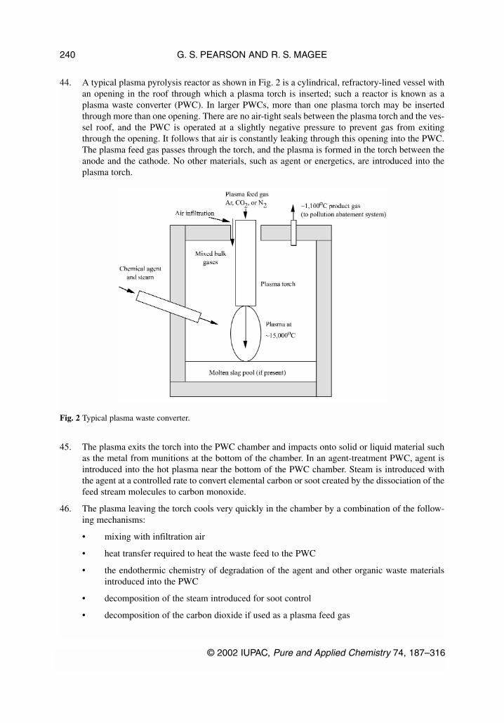
44. A typical plasma pyrolysis reactor as shown in Fig. 2 is a cylindrical, refractory-lined vessel withan opening in the roof through which a plasma torch is inserted; such a reactor is known as aplasma waste converter (PWC). In larger PWCs, more than one plasma torch may be insertedthrough more than one opening. There are no air-tight seals between the plasma torch and the ves-sel roof, and the PWC is operated at a slightly negative pressure to prevent gas from exitingthrough the opening. It follows that air is constantly leaking through this opening into the PWC.The plasma feed gas passes through the torch, and the plasma is formed in the torch between theanode and the cathode. No other materials, such as agent or energetics, are introduced into theplasma torch.
45. The plasma exits the torch into the PWC chamber and impacts onto solid or liquid material suchas the metal from munitions at the bottom of the chamber. In an agent-treatment PWC, agent isintroduced into the hot plasma near the bottom of the PWC chamber. Steam is introduced withthe agent at a controlled rate to convert elemental carbon or soot created by the dissociation of thefeed stream molecules to carbon monoxide.
46. The plasma leaving the torch cools very quickly in the chamber by a combination of the follow-ing mechanisms:
• mixing with infiltration air
• heat transfer required to heat the waste feed to the PWC
• the endothermic chemistry of degradation of the agent and other organic waste materialsintroduced into the PWC
• decomposition of the steam introduced for soot control
• decomposition of the carbon dioxide if used as a plasma feed gas
G. S. PEARSON AND R. S. MAGEE
© 2002 IUPAC, Pure and Applied Chemistry 74, 187–316
240
Fig. 2 Typical plasma waste converter.
• formation of NOx from nitrogen in the munitions materials feed, the plasma feed gas (ifnitrogen), or infiltration air
• heat losses through the PWC shell
47. Agent, after being drained from the munitions, and steam are injected into the PWC where theymix with the hot plasma. Product gas then passes through a pollution abatement system (PAS) andenters a hold-test-release system consisting of a compressor, a condenser, and storage tanks. Thetank contents can then be sampled for agent and other components. If the product gas analysis issatisfactory, e.g., no agent is detected, the gas can be burned on site in a boiler or sold as a fuel.If the gas analysis is unacceptable, it can be recycled through a PWC. Other organic materials cansimilarly be converted to gaseous products, treated in the PAS, and sent to the hold-test-releasesystem described above.
48. Contaminated bodies of projectiles, land mines, etc., drained of agent and with energetic materi-als removed, are fed to a separate PWC. Gaseous products flow through the PAS and the hold-test-release system described previously. Molten metal collects in the bottom of the PWC, whichis tapped periodically, and the metal is cast into ingots.
Scientific principles
49. Electric arcs and discharges have been of interest to scientists and engineers for decades becausethey involve high-temperature, conductive gases (plasmas). Typically, an arc can be establishedbetween two conducting electrodes such as graphite or metal in a variety of atmospheres. Theplasma is composed of molecules, atoms, ions, and electrons at temperatures of 1000 to 20 000 °Cdepending on the current and voltage, the gaseous environment, and the pressure of the con-stricting gas. Either physical or magnetic constriction can be used to increase temperatures.
50. Because plasma arcs between electrodes generally involve voltage drops of 100 V or more, chemi-cal bonds, whose strengths range from 2–10 electron volts (eV) will be broken, and ionizationprocesses (at 4–25 eV) will occur. Thus, material exposed to a plasma environment will be trans-formed into atoms, ions, and electrons with only a few molecules remaining. This makes the poten-tial use of plasma arcs, torches, melters, and other plasma devices attractive for destroying undesir-able molecules such as hazardous wastes. High-temperature plasmas can also produce endothermicneutral species, such as acetylene, cyanogens, and NO, or gaseous molecular ions, such as SiO+ andCO+. When the plasma is cooled to room temperature, most of the molecules are thermodynami-cally unstable, but some traces of metastable species that are stable at higher temperatures but unsta-ble at lower temperatures might survive. In addition, small amounts of metastable species could beformed during cooling, which could also be present at room temperature.
Technology status
51. Research on plasma-arc technology dates back to the early 1900s, and many practical industrialapplications have been developed including arc melting of metals; electric arc welding; plasmaprocessing of ores; plasma spraying of metallic or oxide powders; and plasma generation ofatomic, ionic, and molecular spectra for analytical systems. Plasma arcs have also been used fortreating hazardous wastes. Wastes treated include solvents, paint, batteries, incinerator ash, andradioactive materials. Of the research initiatives by the U.S. Department of Energy and theDepartment of Defense over the past 10 years on plasma treatment of hazardous waste, two havereached the implementation stage: (a) a U.S. Navy project to destroy hazardous materials onshore; and (b) an ongoing asbestos destruction project at Port Clinton, Ohio. Other projects arestill in the research phase. Although organic wastes have been destroyed using plasma-arc fur-naces, much of the research to date has focused on the vitrification of inorganic substances withinwastes (e.g., radioisotopes) rather than on the destruction of organic wastes.
© 2002 IUPAC, Pure and Applied Chemistry 74, 187–316
Critical evaluation of proven chemical weapon destruction technologies 241

52. In addition, plasma pyrolysis has been developed for the destruction of a variety of waste mate-rials including chemical warfare agents in the PLASMOX® process. A plant is being constructedat Munster, Germany to address the disposal of viscous or solid chemical agents and, in particu-lar, arsenicals as well as for the clean-up of arsenically contaminated soil [64]. The processinvolves a soil washing and flotation plant to separate contaminants from the soil. These contam-inants and any arsenical chemical agents are then destroyed by thermal destruction and vitrifica-tion using the PLASMOX process to heat the feed material to temperatures of 1400 to 1600 °Cin a plasma high-temperature reactor, which is a cylindrical chamber with a centrifuge at the bot-tom rotating at about 40 revolutions per minute into which is introduced the feed material. Theplasma torches cause the rotating feed material to pyrolyze. The capacity of the centrifuge isabout 1 m3 which holds about 2 to 5 tonnes of smelt depending on its density. After 4 h, the cen-trifuge is stopped and the melted material is discharged into a slag cart. The quality of the smeltand of the solidified slag, respectively, can be influenced by the use of additives. In the PLAS-MOX process in Germany, the arsenicals are largely transferred into the gas phase because of thehigh temperatures and are precipitated in the PAS scrubbers as iron arsenates. This sludge is driedand put into drums for underground storage. Other heavy metals remain in the slag, which is sim-ilar to glass where they are evenly distributed and firmly bound. The EPA standard leach test inwhich the slag is treated in a slightly acidic environment to simulate the effect over time of acidrain on the dumped material resulted in the various elements in the slag being released in onlyextremely small quantities into the leach test eluate. As an inert substance, this material can beused as a filling material in civil engineering and is not required to go to a hazardous waste land-fill site.
53. Very high destruction efficiencies would be expected at typical plasma pyrolysis temperatures of15 000 °C. However, much of the agent may not be exposed to such a high temperature in theplasma pyrolysis reactor. The plasma arc is created in an enclosed torch through which only theplasma feed gas, such as argon, nitrogen, or carbon dioxide, flows. The arc heats the gas, whichionizes, dissociates, and then flows into the side of the chamber, not through the torch (see Fig. 2).Inside the chamber, the agent mixes with the plasma. The maximum temperature to which eachagent molecule is exposed is unknown, but the temperature gradient within the chamber is verylarge, as the typical exit temperature is around 1100 °C.
54. In the United States, plasma pyrolysis reactors have not been tested with actual munitions orchemical agents. Tests conducted by Acurex Environmental Corporation at the U.S. EPA’s AirPollution Prevention and Control Division of the National Risk Management ResearchLaboratory showed [65] that a PWC could destroy simulants of nerve agents, blister agents, andenergetics, such as thioanisole, dimethyl methylphosphate, tributylphosphate, and dinitrotoluene(DNT), to greater than 99.9999 % destruction efficiencies. Conversion data for those simulantsinclude:
G. S. PEARSON AND R. S. MAGEE
© 2002 IUPAC, Pure and Applied Chemistry 74, 187–316
242
64. H. Martens. “Recovered old arsenical and ‘mustard’ munitions in Germany”, in Arsenic and OldMustard: Chemical Problems in the Destruction of Old Arsenical and ‘Mustard’ Munitions, J. F.Bunnett and M. Mikolajczyk (Eds.), NATO ASI Series, 1. Disarmament Technologies, Vol. 19,pp. 68–76, Kluwer, Dordrecht (1998).
65. Burns and Roe, Assembled Chemical Weapons Assessment Program, proposal submitted inresponse to U.S. Army solicitation No. DAAMO1-97-R-0031, 15 September 1997.

Material Destruction efficiency
Thioanisole >99.999992
Dimethyl methylphosphate >99.999994
Tributyl phosphate >99.999998
Dinitrotoluene (DNT) >99.999996
In Europe, plasma pyrolysis plants using the PLASMOX process have been used to destroy chem-ical agents including lewisite at rates of some 50 kg/h as follows:
• Muttenz, Switzerland, toxic waste, 1 tonne/h, 1990
• AC-Centrum, Spiez, Switzerland, chemical agent, including lewisite, 50 kg/h, 1998
• Munster, Germany, chemical warfare materiel, 700 kg/h, 1999 (trials)
• Wurenlingen, Switzerland, radioactive material, 500 kg/h, 1999 (trials)
55. Based on the many practical applications of plasma technology in the industrial sector, it can beconsidered a robust technology. However, robustness for destroying chemical weapons, and espe-cially large segments of energetic rocket propellants, remains to be demonstrated. Adaptation ofplasma devices of chemical weapons will require (a) special handling equipment for the safeintroduction of shells, rockets, and land mines; and (b) further development of the torch andchamber designed to ensure the destruction of the agent and the production of effluents that canbe scrubbed and burned or converted to slag and sent to a landfill. Meeting these requirementswill require an extended development and testing program. Scale-up from the small plasma pyrol-ysis reactors units in existence to the very large units proposed is likely to present significant sci-entific and engineering challenges.
56. Monitoring of “traditional” process variables such as temperatures, liquid and gas flow rates, etc.is accomplished by using standard, off-the-shelf, chemical process equipment and instrumenta-tion.
Safety considerations
57. The plasma pyrolysis reactors operate at very high temperatures but at slightly negative pressure.Although the plasma temperature is in the range of 15 000 °C, the interior plasma pyrolysis reac-tor wall temperature is expected to be much lower (1650 °C) and the temperature of the exteriorreactor surface will be lower still—about 66 °C. The plasma pyrolysis reactor discharges moltenmetal into ladles for cooling. Although worker interactions with high-temperatureequipment/material or rotating equipment should be minimized by the controls and design fea-tures, worker hazards will probably be higher in the presence of high-temperature systems thanin the presence of lower-temperature systems.
58. A substantial amount of flammable product gas, such as CO, H2, will have to be stored, whetherthe product gas is burned on site or shipped off site. A large explosion or deflagaration involvingthis gas could cause an on-site hazard, and potentially, an off-site hazard from the direct thermaleffects or overpressure forces. A greater concern is the potential damage from explosions to con-tainment structures that could lead to a release of agent. Explosion hazards are common in indus-try and can be minimized by good design and operation.
59. Cooling water is circulated through the plasma torch to keep it from melting at the high plasmatemperatures. A leak in the cooling system could spray water into the plasma. If the leak is sud-
© 2002 IUPAC, Pure and Applied Chemistry 74, 187–316
Critical evaluation of proven chemical weapon destruction technologies 243

den, rapid vaporization could cause a pressure pulse that might overload the downstream gas-han-dling equipment. Untreated agent could, under such circumstances, be released into the sur-rounding room through the torch opening in the top of the plasma pyrolysis reactor.
Environmental impact
60. The plasma pyrolysis plant produces a combustible gaseous product that is first scrubbed toremove any residual contaminants, held and tested prior to release for burning on site or to be soldfor use as fuel. The process is designed to eliminate gaseous air emissions (other than those fromthe burning of the product gas) and liquid discharges. The solid waste created consists of metalingots, which may be sold as scrap, vitrified material, and possibly scrubbber salts. The vitrifiedmaterial should be suitable for land disposal as it should be nonleachable, and the scrubber saltsmight be recycled to the plasma pyrolysis reactor and vitrified with sand to produce a very stablesolid waste, although this has not yet been specifically demonstrated. Consequently, the plasmademilitarization process has the potential to have virtually no impact on the environment.
C. Molten metal technolgy
61. Molten metal, typically iron or nickel, at 1425 to 1650 °C is used to thermally decompose chem-ical warfare agents to simple inorganic molecules such as carbon monoxide, hydrogen, hydrogenfluoride, hydrogen chloride, nitrogen dioxide, sulfur dioxide, and phosphorus pentoxide, whichcan be removed by scrubbing. The molten metal process is also known as Catalytic ExtractionProcessing (CEP), a trademark patented by Molten Metal Technology, Inc.
Process description
62. The molten metal process has been designated by the U.S. Environmental Protection Agency asa non-incineration technology. This distinction between incineration (or combustion) and themolten metal process is based upon different reaction mechanisms and different end-products.The molten metal process is conducted mainly in a molten metal bath at high temperature and lowoxygen potential so that the products are in reduced states such as carbon monoxide and hydro-gen and not, as is the case with incineration in the fully oxidized state, as carbon dioxide andwater.
63. For treating chemical warfare agents, two reactors are required. Each reactor is a steel pressurevessel containing a molten metal bath and an optional slag or flux cover. These reactors are typ-ically operated in the temperature range of 1425 to 1650 °C. The vessel is lined with refractorymaterials selected to provide thermal insulation and resistance to corrosion, erosion, and penetra-tion by components of the bath. An electric induction coil, embedded within the refractory liningsurrounding the metal bath, provides the energy to melt the metal charge and maintain the tem-perature of the bath during processing. The headspace, which is several times the height of themolten metal bath, provides physical space to allow disengagement of the off-gas from the moltenmetal and slag. One or more tapping ports through the vessel sidewall allow recovery of metaland slag phases with minimal interruption of the destruction operation.
64. The feed material and the co-feeds of oxygen and methane can be injected into the molten metalbath either through a lance entering the top of the bath or through one or more bottom-enteringtuyeres. Top-entering lances have been used in numerous bench-scale reactors. A tuyere consistsof three concentric metal tubes cast into a removable refractory block that is bolted into the bot-tom of the reactor. The molten metal process proposes using the tuyere injection of liquid agentand co-feed gases for chemical weapon demilitarization.
65. Feed material, which may be liquid, gas, finely divided entrained solids, or a pumpable slurry, ismetered, mixed, and pumped through the central tube of the tuyere at moderately high pressure,
G. S. PEARSON AND R. S. MAGEE
© 2002 IUPAC, Pure and Applied Chemistry 74, 187–316
244

less than 10 atm. Oxygen, in stoichiometric proportion to convert all carbon in the feed and themethane co-feed to carbon monoxide, is metered into the next annulus at high velocity to induceturbulence, mixing with the feed stream, and formation of a jet that rapidly breaks up into smallbubbles. A small amount of methane is fed through the outer annulus to cool the tuyere.
66. An inert gas is injected automatically into each of the feed lines as necessary to make up the dif-ference between the total flow required in each line and the flow of each feed component (agent,oxygen, and methane). During start-up and shut-down, the inert gas alone is pumped through allfeed lines to prevent molten metal from entering and plugging the tuyere.
Scientific principles
67. The developer of the process describes the molten metal bath as a dissociation catalyst for molec-ular entities in feed materials, a solvent for elemental fragments, and a medium for product syn-thesis. The process can be regarded conceptually as stages comprising catalytic dissociation of thefeed, formation of elemental intermediates with the solvent metal, product synthesis by interac-tion of elemental intermediates, and partitioning of products among metal, slag, and the gasphase.
68. As the NRC AltTech study [66] pointed out, this description does not address initial thermal andgas-phase reactions in the overall sequence of events between the introduction of feeds and therelease of final products. A complete description of the scientific principles requires considera-tion of several additional phenomena including gas-phase reactions among chemical agent, oxy-gen, and methane in the inlet jet; interactions of these gases and intermediate products with metalvapor inside bubbles; and boundary reactions between bubble components and the surroundingmetal. The AltTech study provides a more detailed description of the probable scientific princi-ples and of the probable processes involved.
Technology status
69. As of early 1996, more than 15 000 h of molten metal test experience had been obtained on the10 to 15 bench-scale units, which have nominal bath sizes of 4 to 9 kg. However, this experiencehas been on commercial waste when a wide range of materials have been processed includingpolystyrene with graphite, ion-exchange resins, acetone, industrial biosolid waste, chlorotoluenewith heavy organic substances, chlorobenzene, fuel oil with chlorotoluene, dimethyl acetamidewith heavy organic substances, benzonitrile, diazinon, diazinon with sulfur, and surplus metalcomponents. These materials have been in various physical forms, including liquids, slurries, finesolids, and bulk solids. Injection rates comparable with commercial levels have been demon-strated at both the demonstration-scale and advanced processing units.
70. The experience of chemical warfare agent testing has been limited to evaluation in a bench-scaleunit at the Battelle/Columbus Laboratory. The AltTech panel in their review of the results of thesetests concluded [67] that the molten metal process can destroy chemical warfare agent to at least99.9999 % [known as a destruction removal efficiency (DRE) of six 9s]. The specific agent pro-cessing rates used were small:
© 2002 IUPAC, Pure and Applied Chemistry 74, 187–316
Critical evaluation of proven chemical weapon destruction technologies 245
66. National Research Council, Panel on Review and Evaluation of Alternative Chemical DisposalTechnologies. Review and Evaluation of Alternative Chemical Disposal Technologies, pp. 28–33,National Academy Press, Washington, DC (1996).
67. National Research Council, Panel on Review and Evaluation of Alternative Chemical DisposalTechnologies. Review and Evaluation of Alternative Chemical Disposal Technologies, p. 35,National Academy Press, Washington, DC (1996).

Agent Bath Agent processing ratetested composition (kg agent/h/1000 kg bath metal)
HD Ni + 2 % C 7VX Fe + 7 % P + 7 % S + C 8
71. The molten metal technology was not recommended in the NRC AltTech study [68] for furtherdevelopment and implementation at the two bulk agent storage sites at Aberdeen and Newport.Subsequently, Molten Metal Technology, Inc., filed for bankruptcy, and development of the tech-nology for chemical demilitarization has ceased.
Safety considerations
72. Process-safety risks for the molten metal process can be divided into two categories: (1) risksrelated to handling agent prior to its introduction into the molten metal bath and (2) risks relatedto the molten bath technology.
73. The risk factors inherent in the handling of agent prior to entry into the reactors include storagerisk, transportation risk, and the risk from the punch-and-drain operation. These risk factors arecommon to all the agent-destruction technologies reviewed in this report, but they can be exacer-bated or ameliorated by aspects of a specific technology. For example, how quickly a facilityusing the technology can reach operational status or the rate at which the agent can be processedwith that technology can alter the storage risk by changing the length of time that the agent needsto be stored. The process-safety risk factors inherent in the molten metal process include issuesassociated with high-temperature molten baths such as the integrity of the refractory confinement,the proximity of the molten bath to water-cooling coils (raising the possibility of steam explo-sions), the behavior of the tuyeres, and the instrumentation for monitoring the refractory confine-ment.
Safety issues related to off-site releases
74. The following issues need to be addressed fully and clearly in a final molten metal process design:
Integrity of the refractory. The integrity of the refractory needs to be included in the safety docu-mentation for a molten metal design. The company has done much work to avoid gas-jet impinge-ment on the refractory lining of the reactor and to select refractory materials for the lining thatresist gas permeation, thermal degradation, corrosion, erosion, and penetration by components ofthe molten metal and slag.
Integrity of components exposed to agent. Comprehensive safety and hazard analyses are neededas part of the development process. Particularly important is further exploration of scenariosinvolving failures of piping or components. (Failure could be caused by thermal attack by moltenmaterial, system overpressure, subtle system interactions, or other causes.)
Cooling off-gas piping. Scenarios involving a failure to cool the off-gas piping need to beexplored, as the consequences of such scenarios were not clear.
G. S. PEARSON AND R. S. MAGEE
© 2002 IUPAC, Pure and Applied Chemistry 74, 187–316
246
68. National Research Council, Panel on Review and Evaluation of Alternative Chemical DisposalTechnologies. Review and Evaluation of Alternative Chemical Disposal Technologies, NationalAcademy Press, Washington, DC (1996).
Buildup of combustible gases. The design as submitted for the NRC AltTech review prevents abuildup of combustible gases in the vicinity of the system by maintaining a high ventilation rate.Assurances should be made that combustible gas build-up cannot occur and that the high ventila-tion rate does not compromise the design capability to contain leakage of agent.
Worker safety issues
75. There are a number of worker safety issues associated with high-temperature molten baths, high-temperature corrosives in the scrubbers, and secondary containment (concerning both inadvertentleaks and maintenance activities). These risk factors need to be addressed in the design, and real-istic emergency responses need to be spelled out.
Environmental impact
Test prior to release
76. Although the molten metal process is a tightly integrated continuous process, the technology pro-vides for synthesis gas (“gaseous residuals”) to be held for analytical testing prior to combustion.The products of combustion, however, are not tested prior to release to the atmosphere. Metal, sul-fur, and ceramic process residuals are solids and will be tested prior to shipment off site.Recovered hydrochloric acid will also be tested prior to off-site shipment.
Environmental burden
77. The technology is designed to minimize the environmental burden by producing metal,hydrochloric acid, and elemental sulfur as by-products that can be offered on the commercial mar-ket for reuse. The technical and economic feasibility of marketing these by-products has yet to beestablished. The process design also includes burning the off-gas, which is rich in hydrogen andcarbon monoxide, in a gas turbine to generate electricity for in-plant use. The ceramic slag willrequire disposal.
D. Hydrogenolysis
Process description
78. This process uses hydrogen and steam at elevated temperatures (up to 850 °C) and nominallyatmospheric pressure to transform organic wastes into simpler substances that are either less toxicor convertible to less toxic materials; these simpler substances are also easier and safer to reuseor to release to the environment. The overall process requires a high-temperature reaction vessel,where the chemical reduction occurs, followed by a gas-scrubbing train to remove inorganic by-products, and thus produces a useable process gas. This process gas is burned in an on-site steamboiler to support the operation. The process also includes provisions for removing other by-prod-ucts and regenerating hydrogen gas through steam reforming.
79. Chlorinated hydrocarbons, such as polychlorinated biphenyls (PCBs), are chemically brokendown and reduced to methane (CH4) and hydrogen chloride (HCl) with carbon monoxide (CO)and carbon dioxide (CO2) as by-products. Nonchlorinated aromatic hydrocarbons such as tolueneare reduced primarily to methane, with minor amounts of other light hydrocarbons. Carbon andpresumably some heavier hydrocarbons are also produced.
80. The flow-through stainless steel reactor has nozzles to accelerate the vaporization or dispersionof liquid waste material inputs, which are injected directly into the reactor mix of hot gases con-sisting of hydrogen (H2), water vapor (H2O), carbon monoxide (CO), and carbon dioxide (CO2).Within the reactor, radiant-tube heaters heat the mixture to 850 °C. The residence time in the reac-tor is 2 to 6 s, although reactions are expected to occur in less than 1 s.
© 2002 IUPAC, Pure and Applied Chemistry 74, 187–316
Critical evaluation of proven chemical weapon destruction technologies 247

81. The gases exiting the reactor are scrubbed to remove by-products. Water is used as a quench todecrease the gas temperature and absorb water-soluble products, including hydrogen chloride(HCl). These and other acidic products are further scrubbed by caustic scrubbers. A heavy-oilscrubber can be used in the scrubber train to remove some hydrocarbons. A standardmonoethanolamine (MEA) scrubbing system removes most of the hydrogen sulfide (H2S) (pro-duced from sulfur-containing feeds) and carbon dioxide (CO2) from the gas train. The separatedhydrogen sulfide (H2S) requires further treatment to convert it to elemental sulfur and water.
82. Hydrogenolysis has been under development since 1986 and has progressed from bench-scaletesting through to commercial-scale operation. A number of organic feed materials, particularlychlorinated wastes, have been tested at bench scale. Several kinds of feed materials are currentlybeing treated at commercial scale (tonnes per day), including pesticides, chlorinated hydrocar-bons, and PCBs. Two full-scale plants have been operating for more than three years in Kwinanain Western Australia, and one plant was operated for a year (1996) at a General Motors of Canadafacility in St. Catherine’s, Ontario.
Scientific principles
83. The chemistry by which hydrogenolysis destroys organic feed material is much more complexthan a simple high-temperature reduction with hydrogen of organic compounds to producemethane. The complexity results from the reduction with hydrogen being accompanied by reac-tions of carbonaceous intermediates, including elemental carbon, with steam to yield the finalproducts. Although the thermodynamic principles of reducing organic substances with hydrogento carbon and the resulting reactions of carbon with steam (carbon-steam chemistry) have beenthoroughly studied and are well understood, the interplay of kinetics and thermodynamics in thehydrogenolysis reactor are less well known.
84. The chemical agents mustard, GB, and VX contain a high proportion of heteroatoms (atoms otherthan carbon, hydrogen, or oxygen, such as chlorine, phosphorus, sulfur, or nitrogen). The reac-tion products containing these heteroatoms will generate a large volume of inorganic processresiduals. For example, mustard is by weight 45 % chlorine, 20 % sulfur, and 30 % carbon; VXis by weight 12 % phosphorus, 5 % nitrogen, 12 % sulfur, and 49 % carbon with the balance beingmade up of hydrogen and oxygen. This heteroatom content raises two uncertainties. First, whatare the final heteroatom products from the reactor? Second, how are they to be scrubbed or oth-erwise removed? The acid gases and other inorganic products need to first be scrubbed from thereactor effluent gas and then converted to a form suitable for disposal or recycling in commerce.The reaction products or organic compounds containing heteroatoms are even more difficult topredict without the same kind of detailed experimental work that has been carried out on the feedmaterials currently treated successfully at the commercial facilities.
85. There is considerable operational experience treating a number of highly halogenated wastes suchas PCBs, hexachlorobenzene, and 2,2-bis(4-chlorophenyl) 1,1,1-trichloroethane (DDT), whichhas shown empirically that a fine balance of hydrogen and steam is necessary to avoid generatingsubstantial amounts of carbon and polyaromatics in the reactor. Empirical models have beendeveloped to predict operating parameters that yield optimal product composition: primarilymethane, with CO and CO2.
86. For simple hydrocarbons, hydrogenolysis is a high-temperature reduction by hydrogen to producemethane. Simple thermodynamic calculations reveal, however, that considerable amounts of car-bon would be expected from the initial reaction with hydrogen. Consequently, this carbon willreact subsequently with H2O to generate CO, CO2, and, ideally, more hydrogen. Some high-molecular-weight carbon residue is also generated. This postulated reaction process is supported
G. S. PEARSON AND R. S. MAGEE
© 2002 IUPAC, Pure and Applied Chemistry 74, 187–316
248

by the results obtained. Steam is added to the hot feed gas to react with the carbon to form CO2and CO; the H2 content of the reactant gas is maintained above 55 %, as this is a level at whichexperience indicates the major product will be methane.
87. Feed materials that contain heteroatoms will yield products that contain these elements in prod-ucts such as acid gases [e.g., hydrogen chloride (HCl)] and reduced inorganic substances [e.g.,hydrogen sulfide (H2S)]. Chlorinated wastes yield HCl as a primary product. The clean formationof HCl under the reaction conditions can be understood in terms of simple thermodynamics, giventhat chlorine will probably not produce many other products under the reaction conditions.
Technology status
88. Hydrogenolysis has been used to treat organic wastes, including PCBs, other chlorocarbons, andhydrocarbons such as toluene. A significant amount of work has been conducted at laboratory,pilot, and commercial scales.
89. Pilot-scale work has been performed since 1991 at several sites in the United States and Canada.A laboratory-scale system is available for waste treatability studies and this system has been usedfor preliminary tests on agent surrogates, such as the organophosphorus pesticide malathion.Pilot-scale demonstrations have been performed on several materials, including polyaromatichydrocarbons at Hamilton Harbor, Ontario, in 1991 and PCBs (PCB-contaminated soil) at BayCity, Michigan, in 1992.
90. Commercial units are currently being operated in Australia and have been operated in Canada,and others are being constructed. Hydrogenolysis is being used to treat a mixture of DDT andtoluene on a commercial scale in Australia. Another system at St. Catherines, Ontario, processedPCBs both as a concentrated material and in PCB-contaminated concrete, for General Motors. Fortreating these feedstocks, the status of the technology is advanced, since there are commercialfacilities in operation.
91. Full operational manuals, hazard and operability studies, process and instrument diagrams, andrisk analyses have been developed and documented for processing DDT-toluene mixtures andPCBs.
92. The experience with organic wastes forms a basis for applying the technology to agent destruc-tion, but further development that is specific to the chemical agents to be treated is still required.For instance, all hydrogenolysis operations to date have been carried out in the open air. Agent-destruction facilities, however, will require containment of all unit processes where agent may bepresent. Consequently, this need to contain hydrogen gas within a building can be hazardous.Hazardous-operation procedures for handling these conflicting safety demands need to beaddressed.
93. In summary, the main uncertainty in applying this process to agent destruction centers on identi-fying and managing the inorganic by-products derived from the sulfur, phosphorus, and nitrogenin the agents. The primary inorganic products from the reactor need to be identified and processesdeveloped to remove and manage them downstream.
94. The systems currently used should work well for mustard destruction after modification of thescrubber train to handle the large product load of H2S. The status of the technology for mustardtreatment is near commercial except for: (1) the lack of demonstrated handling of large volumesof hydrogen sulfide (H2S), (2) the overall process demonstration on mustard itself (small-scaletests to show the process can destroy agent have been successful), and (3) the resolution of sec-ondary containment and safety issues specific to processing chemical warfare agents and con-tainment of hydrogen gas.
© 2002 IUPAC, Pure and Applied Chemistry 74, 187–316
Critical evaluation of proven chemical weapon destruction technologies 249

95. Because much less is known on both a fundamental and practical level about the identity and han-dling of phosphorus-containing residuals from hydrogenolysis, the technology for VX destructionis less mature than it is for mustard. The technology developer has little experience with phos-phorus-containing materials, even at bench scale.
Safety considerations
96. The risk factors for process safety can be divided into two categories: factors related to handlingagent prior to its introduction into the specific technology and factors related to the agent-destruc-tion technology and associated system elements. The process-safety risk factors related to thehandling of agent prior to entry into this technology, which are common to all the agent-destruc-tion technologies, include storage risk, transportation risk, and the risk from the punch-and-drainoperation. These factors can be exacerbated or ameliorated by unique aspects of a technology.
97. The process-safety risk factors inherent in hydrogenolysis include safety issues associated withhigh-temperature hydrogen, hot water and corrosives in the scrubbers, and secondary contain-ment. Many of the risk factors that are not specific to chemical agent have been addressed insafety analyses and in hazard and operability reports.
98. No failure scenarios involving a loss of electrical power, loss of cooling, failures of pumps andvalves, inadvertent overpressurization, or inadvertent temperature transients were identified in theNRC AltTech report [69] that would lead to off-site releases of agent or toxic process products.The most significant off-site risk appeared to be associated with handling agent prior to the agent-destruction process. The principal risk factors appeared to involve mishaps in the punch-and-drainoperation or damage from airplane crashes or other external events to holding tanks where agentis stored before being fed to the main reactor.
99. The following subsections on process safety address risk factors specific to hydrogenolysis tech-nology.
Hydrogen and other combustible gases
100. The process uses hydrogen. In addition to the hydrogen circulating in the process gas stream,most of which is produced in the steam reformer from methane produced in the main reactor,compressed hydrogen is stored in tube trailers and in the product gas tank. Other combustiblegases (carbon monoxide, propane) are also present and need to be considered.
101. Hydrogen is commonly used in industry and can be used safely. Recent industrial accidents involv-ing hydrogen are rare because of the care taken to handle it properly. However, because of the poten-tial for a hydrogen explosion or fire to cause grave damage to personnel and structures if the hydro-gen is not managed properly, it has to be considered. Also, a hydrogen explosion could lead to arelease of chemical agent. Although leaks of flammable gases are a risk factor for worker safety,they are not currently an off-site risk factor in either of the two current commercial operations.
102. When a hydrogenolysis system is housed in secondary containment (as is required for agent-destruction facilities), the potential increases for build-up of an explosive concentration of hydro-gen. The potential also increases for damage to agent-bearing structures from an explosion or fire.The containment of the system for an agent-destruction facility will need to be designed so thatthe hydrogen will neither stratify nor build up locally to a combustible concentration.
G. S. PEARSON AND R. S. MAGEE
© 2002 IUPAC, Pure and Applied Chemistry 74, 187–316
250
69. National Research Council, Panel on Review and Evaluation of Alternative Chemical DisposalTechnologies. Review and Evaluation of Alternative Chemical Disposal Technologies, NationalAcademy Press, Washington, DC (1996).

103. A large detonation or burn near the containers that store the agent could damage containmentstructures and cause a release of agent. This risk factor needs to be considered when designingcomponent locations and shielding. The hydrogen tube trailer, product gas tank, or any other com-bustible storage area should be located a safe distance away from the agent-containing compo-nents (holding tank, reactor).
Gas-phase chemical reduction
104. Another risk factor that needs to be considered is from combustible mixtures of air and hydrogeninside the circulating-gas system, which could result from air leaking into the system combinedwith flow imbalances. The current industrial systems have design features and controls in placethat appropriately address this risk.
Environmental impact
Test prior to release
105. The process gas stream that goes to the steam boiler for combustion is held in tanks and testedprior to combustion, although the products of combustion are not tested prior to release throughthe stack. Solid and liquid residuals are tested prior to release.
Environmental burden
106. Aside from the uncertainties about phosphorus, all the inorganic substances derived from the het-eroatoms present in the agent are ultimately converted to common salts, salt solutions, or ele-mental sulfur. These will require proper landfill disposal. The steam boiler, which burns a mix-ture of process gas and propane, discharges combustion products through a stack to theatmosphere. The issues typically raised about trace products of inorganic combustion and therelease of combustion products to the environment need to be addressed if this technologyapproach is to be implemented.
E. Destruction of arsenicals
Although chemical weapon agents containing arsenic can be destroyed by both high-temperature andlow-temperature destruction technologies, the destruction of arsenicals is addressed in this reportunder high-temperature destruction technologies as this approach is continuing to be used inGermany.
Introduction
107. A number of chemical warfare agents based on organic compounds containing arsenic weredeveloped during World War I and were stockpiled both then, during the interwar years and inWorld War II. Initially, some organoarsenic compounds could penetrate the filters in early gasmasks, which were designed to absorb chlorine and phosgene, and because the organoarsenicagents (Clark agents) were vomiting agents they caused the wearers to remove the masks.Another advantage was that the addition of organic arsenical compounds to mustard reduced thefreezing point of mustard from 14 °C, making the mustard/arsenical agent easier to use under coldweather conditions. Mustard-lewisite mixtures had freezing points ranging from –24 to –42 °C
© 2002 IUPAC, Pure and Applied Chemistry 74, 187–316
Critical evaluation of proven chemical weapon destruction technologies 251

depending on the ratio of the mixture. The most important agents containing arsenic are shown inthe table below [70]:
Agent Chemical name Symbol Agent type
Lewisite 2-chlorovinyldichloroarsine L Vesicant andsystemic poison
Mustard/lewisite Mixture of mustard and HL Vesicantlewisite
Phenyldichloroarsine Phenyldichloroarsine PD Vomiting andvesicant properties
Ethyldichloroarsine Ethyldichloroarsine ED Vomiting andvesicant properties
Methyldichloroarsine Methyldichloroarsine MD Vomiting andvesicant properties
Diphenylchloroarsine Diphenylchloroarsine DA, Clark I Vomiting agentAdamsite 10-chloro-5,10-dihydrophenarsine DM Vomiting agentDiphenylcyanoarsine Diphenylcyanoarsine DC, Clark II Vomiting agent
In addition, a number of mixtures containing arsenic compounds, such as arsenic trichloride, werealso produced and deployed in World War I munitions.
108. Arsenic-containing chemical weapon agents were produced and stockpiled by a number of coun-tries during the period 1930–1945 [71]:
Country Lewisite Diphenyl Diphenyl AdamsiteL chloroarsine DA cyanooarsine DC DM
France Yes YesGermany Yes YesItaly Yes Yes YesJapan Yes Yes YesUK Yes Yes Yes YesUSA Yes YesUSSR Yes Yes
G. S. PEARSON AND R. S. MAGEE
© 2002 IUPAC, Pure and Applied Chemistry 74, 187–316
252
70. Developed from Table 2.1 in K. Lohs and T. Stock, “Characteristics of chemical warfare agentsand toxic armament wastes”, in The Challenge of Old Chemical Munitions and Toxic ArmamentWastes, T. Stock and K. Lohs (Eds.), SIPRI Chemical and Biological Warfare Studies, No. 16,Oxford University Press (1997) and from Table 2 in R. G. Manley, “The problem of old chemi-cal weapons which contain “mustard gas” or organoarsenic compounds: An overview”, in Arsenicand Old Mustard: Chemical Problems in the Destruction of Old Arsenical and ‘Mustard’Munitions, J. F. Bunnett and M. Mikolajczyk (Eds.), NATO ASI Series, 1. DisarmamentTechnologies, Vol. 19, Kluwer, Dordrecht (1998).
71. Based on Table 4 in R. G. Manley, “The problem of old chemical weapons which contain “mus-tard gas” or organoarsenic compounds: An overview”, in Arsenic and Old Mustard: ChemicalProblems in the Destruction of Old Arsenical and ‘Mustard’ Munitions, J. F. Bunnett and M.Mikolajczyk (Eds.), NATO ASI Series, 1. Disarmament Technologies, Vol. 19, Kluwer, Dordrecht(1998).

Today, the proportion of the U.S. stockpile of chemical weapons and agents that contain arseni-cal agents is limited to 10 one-ton containers of lewisite at Tooele Army Depot corresponding toaround 0.03 % of the total U.S. stockpile. Russia has the world’s largest stockpile of lewisite withabout 7000 tonnes of lewisite in both containers and filled into weapons [72]. It is also known thatJapan produced quantities of lewisite and DC (Clark II) [73] during World War II. In Europe, oldchemical weapons containing any of the arsenical agents are found from time to time.
Scientific principles
109. Insofar as the arsenicals that were produced and stockpiled during the period 1930 to 1945 areconcerned, their behavior in water provides some insight into ways in which they may bedestroyed [74]. The hydrolysis of diphenylchloroarsine (DA, Clark I) produces diphenylarseniousacid and hydrochloric acid, while diphenylcyanoarsine (DC, Clark II) produces diphenylarsinousoxide and hydrocyanic acid. Both diphenylarsenious acid and hydrocyanic acid are toxic butquickly detoxify in water. The organoarsenic compounds may later decompose to toxic inorganicarsenic compounds. Adamsite (DM) hydrolyses very slowly in water and is almost insoluble. Itsreaction products are diphenylarsinous acid and hydrochloric acid. It can, however, be hydrolyzedby phosphorous acid yielding arsenic, diphenylamine, hydrochloric acid, and phosphates. It isalso hydrolyzed by concentrated hydrochloric acid yielding arsenic trichloride and diphenylaminehydrochloride [75]. Lewisite is only slightly soluble, but when it dissolves it hydrolyzes rapidlyinto 2-chlorvinylarsine oxide. The real problem that has to be faced in addressing the destructionof arsenicals is that the products of destruction will themselves still contain arsenic in some formor another and thus still be toxic. The technology status is considered first for lewisite and thenfor Adamsite.
Technology status—lewisite
110. Most attention has been given to the destruction of lewisite, as this is the arsenical that hasbeen most widely stockpiled and still has to be destroyed today. Various alternative
© 2002 IUPAC, Pure and Applied Chemistry 74, 187–316
Critical evaluation of proven chemical weapon destruction technologies 253
72. S. V. Petrov, V. I. Kholstov, V. P. Zoubrilin, N. V. Zavialova. “Practical actions of Russia on prepa-rations for destruction of stockpiled Lewisite and ‘mustard’”, in Arsenic and Old Mustard:Chemical Problems in the Destruction of Old Arsenical and ‘Mustard’ Munitions, J. F. Bunnettand M. Mikolajczyk (Eds.), NATO ASI Series, 1. Disarmament Technologies, Vol. 19, Kluwer,Dordrecht (1998).
73. R. G. Manley. “The problem of old chemical weapons which contain “mustard gas” ororganoarsenic compounds: An overview”, in Arsenic and Old Mustard: Chemical Problems in theDestruction of Old Arsenical and ‘Mustard’ Munitions, J. F. Bunnett and M. Mikolajczyk (Eds.),NATO ASI Series, 1. Disarmament Technologies, Vol. 19, p. 8, Kluwer, Dordrecht (1998). Seealso information available at http://www.tcp-ip.or.jp/~e-ogawa/BRIEFING.HTM#faq9
74. K. Lohs and T. Stock. “Characteristics of chemical warfare agents and toxic armament wastes”,in The Challenge of Old Chemical Munitions and Toxic Armament Wastes, T. Stock and K. Lohs(Eds.), SIPRI Chemical and Biological Warfare Studies, No. 16, p. 47, Oxford University Press(1997).
75. Z. Wertejuk, M. Koch, W. Marciniak. Recovered Old Arsenical and ‘Mustard’ munitions inPoland, in Arsenic and Old Mustard: Chemical Problems in the Destruction of Old Arsenical and‘Mustard’ Munitions, J. F. Bunnett and M. Mikolajczyk (Eds.), NATO ASI Series, 1.Disarmament Technologies, Vol. 19, Kluwer, Dordrecht (1998).
approaches for the destruction of lewisite in the Russian stockpile have been identified [76].These include:
a. Treatment with sulfur at temperatures of 160–180 °C using a lewisite/sulfur mass ratio of1/3 with a reaction time of 30–40 min producing a tough polymeric mass which can beburied in special burial grounds. The main disadvantage is the mass of polymeric materialproduced and the need to bury it away from underground aquifers.
b. Reaction with ethyleneglycol monomethacrylate ester and its subsequent polymerization at60–90 °C. However, as with the sulfur treatment, the main disadvantage relates to the bur-ial and prevention of aquifer contamination.
c. Chlorination with gaseous chlorine at 110–130 °C produces arsenic trichloride and a mix-ture of chlorinated hydrocarbons. The main shortcomings are that the conversion of lewisiteis not complete and the chlorinated hydrocarbons are toxic.
d. Alkaline hydrolysis for 1 h at 103–110 °C using aqueous alkali can achieve full decompo-sition of the lewisite. Subsequent electrolysis yields metallic arsenic.
e. Alcoholysis using alcoholic solutions of sodium alkoxides at 50–80 °C for 2–3 h producesacetylene, sodium chloride, and a trialkyl arsenite. However, the treatment is regarded asbeing unsuitable, as the trialkyl arsenite is toxic and flammable.
f. High-temperature oxidation in which lewisite is completely oxidized in the flame of a gasburner at over 600 °C. Although the method is regarded as being reliable for destruction oflewisite and it is possible to recover and store the arsenic oxide, it is suggested that the burn-ing of lewisite can produce toxic chemicals such as dioxins [77].
g. Hydrogenolysis in which lewisite is destroyed at 800–1000 °C by treatment with hydrogendiluted with nitrogen. The disadvantage is the presence of toxic agents at high temperaturestogether with hydrogen and hydrogen chloride. There is also the possibility that toxicarsine, AsH3, may be produced.
h. Ammonia reduction at 1000–1100 °C producing elemental arsenic. The disadvatage is thehigh temperature and the large quantity of ammonia.
The approach reported in the late 1990s as having been selected as the preferred technology inRussia for the destruction of lewisite is that of alkaline hydrolysis by hot sodium hydroxide fol-lowed by subsequent electrolysis.
ClCH=CHAsCl2 + 6NaOH = Na3AsO3 + C2H2+ 3NaCl + 3H2O
Na3AsO3 + 3H+ + 3 e– = As + 3NaOH
G. S. PEARSON AND R. S. MAGEE
© 2002 IUPAC, Pure and Applied Chemistry 74, 187–316
254
76. S. V. Petrov, V. I. Kholstov, V. P. Zoubrilin, N. V. Zavialova. “Practical actions of Russia on prepa-rations for destruction of stockpiled Lewisite and ‘mustard’”, in Arsenic and Old Mustard:Chemical Problems in the Destruction of Old Arsenical and ‘Mustard’ Munitions, J. F. Bunnettand M. Mikolajczyk (Eds.), NATO ASI Series, 1. Disarmament Technologies, Vol. 19, p. 79,Kluwer, Dordrecht (1998).
77. S. V. Petrov, V. I. Kholstov, V. P. Zoubrilin, N. V. Zavialova. “Practical actions of Russia on prepa-rations for destruction of stockpiled Lewisite and ‘mustard’”, in Arsenic and Old Mustard:Chemical Problems in the Destruction of Old Arsenical and ‘Mustard’ Munitions, J. F. Bunnettand M. Mikolajczyk (Eds.), NATO ASI Series, 1. Disarmament Technologies, Vol. 19, p. 79,Kluwer, Dordrecht (1998).

111. Canada in the early 1990s carried out the destruction of 1.5 tonnes of lewisite [78]. A three-stepneutralization process was used [79]:
a. Oxidation of lewisite to 2-chlorovinylarsonic acid by addition of lewisite to aqueous caus-tic hydrogen peroxide under controlled pH conditions:
ClCH=CHAsCl2 + H2O2 + 2 NaOH = ClCH=CHAsO3H2 + 2NaCl + H2O
b. Removal of excess hydrogen peroxide by circulating through a catalyst bed containingmanganese dioxide, thereby causing decomposition to water and oxygen
2H2O2 = 2H2O + O2
c. Conversion of the 2-chlorovinylarsonic acid to sodium arsenate and sodium chloride andfree acetylene by the addition of sodium hydroxide. This step was carried out under nitro-gen while bleeding off the acetylene to atmosphere.
ClCH=CHAsO3H2 + 2HCl + 6NaOH = Na3AsO4 + C2H2 + 3NaCl + 5H2O
This stage is important to ensure that no hydrogen peroxide remains in the third stage whenacetylene is produced.
After analysis to verify the efficiency of lewisite destruction, batches of the arsenic salt solutionwere mixed with sodium silicate and cement to produce a concrete stabilized final product, whichwas cured in 210 L polyethylene barrels which then went to a landfill site. The United States inthe late 1990s is examining this process for the destruction of its 13 ton (11.8 tonne) stockpile oflewisite held at Tooele.
Technology status—mixtures containing arsenic compounds
112. In Germany, an incineration plant at Munster has been used to destroy several arsenicals includ-ing Clark agent and mustard-containing various arsenical compounds [80]. Prior to incineration,the chemicals to be destroyed are analyzed for the presence of arsenicals and batches for destruc-tion are made up on the basis of this analysis. In the Munster incineration process, agent is firstevaporated and subjected to partial pyrolysis at 300 °C for up to 12 h. The vaporized agent is thenpassed through the main combustion chamber at temperatures of 1000 to 1200 °C with a resi-dence time of 2 s. The product gas is then cooled rapidly to 80 °C by the injection of cooling waterand then passed through two scrubbing towers washed with aqueous sodium hydroxide to neu-tralize the sulfur dioxide and hydrogen chloride as well as arsenic oxide (As2O3). The flue gaspasses through an aerosol separator, which removes any remaining liquid or solid particles suchas arsenic oxide (As2O3) before it is discharged through the stack. If the material to be destroyedcontains arsenic, then the wastewater has to be subjected to supplementary treatment, as the incin-eration of the organic arsenic compounds produces arsenic trioxide which is then scrubbed into
© 2002 IUPAC, Pure and Applied Chemistry 74, 187–316
Critical evaluation of proven chemical weapon destruction technologies 255
78. R. G. Sutherland. “The destruction of old and obsolete chemical weapons: Past experience”, inThe Challenge of Old Chemical Munitions and Toxic Armament Wastes, T. Stock and K. Lohs(Eds.), SIPRI Chemical and Biological Warfare Studies, No. 16, p. 150, Oxford University Press(1997).
79. J. M. McAndless, V. Fedor, T. Kinderwater. Destruction and Waste Treatment Methods used in aChemical Agent Disposal Project, DRES Suffield Memorandum No. 1392, October 1992.
80. Hermann Martens. “The German programme for the disposal of old chemical weapons”, in TheChallenge of Old Chemical Munitions and Toxic Armament Wastes, T. Stock and K. Lohs (Eds.),SIPRI Chemical and Biological Warfare Studies, No. 16, pp. 171–175, Oxford University Press(1997).

the aqueous sodium hydroxide as trivalent arsenite. Conversion of these compounds into insolu-ble arsenic compounds requires oxidation using potassium permanganate or hydrogen peroxidein order to produce pentavalent arsenates. When ferric chloride is added, precipitation of insolu-ble iron arsenate occurs. The resulting sludge material is dehydrated in a filter press and thenfilled into drums for final deposit in an underground waste dump. The waste air and wastewaterdata for the Munster facility in 1993 were approximately 0.2 mg/m3 for arsenic in the waste airemission compared to the allowable level of 1.0 mg/m3 and adjusted to less than the limit of 1 mg/L in wastewater.
113. A second incineration plant was recently constructed at Munster to address the disposal of vis-cous or solid chemical agents and, in particular, arsenicals as well as for the clean up of arseni-cally contaminated soil [81]. The process involves a soil-washing and flotation plant to separatecontaminants from the soil. These contaminants and any arsenical chemical agents are thendestroyed by thermal destruction and vitrification using high-temperature plasma technology,which is described in the section above on plasma pyrolysis (Section VI.B). This high-tempera-ture plasma technology (PLASMOX process) is used to heat the organic chemical feed materialto temperatures of 1400 to 1600 °C in a plasma high-temperature reactor which is a cylindricalchamber with a centrifuge at the bottom into which is introduced the feed material. The plasmatorches cause the rotating organic chemical feed material to pyrolyze. After 4 h, the centrifuge isstopped and the melted material is discharged into a slag cart. Heavy metals such as arsenicremain in the slag, which is similar to glass where they are evenly distributed and firmly bound.The EPA standard leach test in which the slag is treated in a slightly acidic environment to simu-late the effect over time of acid rain on the dumped material resulted in the various elements inthe slag being released in only extremely small quantities into the leach test eluate. As an inertsubstance, this material can be used as a filling material in civil engineering and is not requiredto go to a hazardous waste dumping site. In Germany, two important aspects have to be taken intoaccount in regard to the possible disposal of slag: (a) leachability and (b) the amount of toxicmaterial per kg of slag. Slag with an arsenic content of more than 2 % would have to be set asidefor underground storage.
114. As already noted in section VI.B on plasma pyrolysis, the PLASMOX process has been used inEurope to treat toxic waste, radioactive materials, and chemical agent as follows:
• Muttenz, Switzerland, toxic waste, 1 tonne/h, 1990
• AC-Centrum, Spiez, Switzerland, chemical agent, including lewisite, 50kg/h, 1998
• Munster, Germany, chemical warfare materiel, 700kg/h, 1999 (trials)
• Wurenlingen, Switzerland, radioactive material, 500kg/h, 1999 (trials)
Technology status—Adamsite
115. Adamsite can be reduced [82] using phosphorous acid, according to the following equation:
2C6H4·NH·AsCl·C6H4 + 3H3PO3 → 2Ph2NH2Cl + 2As + 3HPO3
G. S. PEARSON AND R. S. MAGEE
© 2002 IUPAC, Pure and Applied Chemistry 74, 187–316
256
81. Hermann Martens. “Recovered old arsenical and ‘mustard’ munitions in Germany”, in Arsenicand Old Mustard: Chemical Problems in the Destruction of Old Arsenical and ‘Mustard’Munitions, J. F. Bunnett and M, Mikolajczyk (Eds.), NATO ASI Series, 1. DisarmamentTechnologies, Vol. 19, pp. 68–76, Kluwer, Dordrecht (1998).
82. S. Neffe. “Polish Experience in Safe Disposal of Arsenic Containing Chemical Warfare Agents”,in Proceedings of the International CW Destruction Symposium, V. Starrock and A. Krippendorf(Eds.), Munster, Germany, 22–25 March 1998.

In this reaction, the actual reducing agent is phosphine (PH3), which is formed through the dis-proportionation of phosphorous acid:
4H3PO3 → PH3 + 3H3PO4
2H3PO4 → H2O + H4P2O7
116. The reagents for the destruction of Adamsite are phosphorous and phosphoric acid, sodiumhydroxide, sodium hypochlorite, and water. The process is irreversible and produces high-purity,dispersed metallic arsenic, diphenylamine (DPA), hydrochloric acid, and phosphates. The speedof the reduction reaction can be increased by increasing the temperature of reacting mixture.
117. This technology has been recently used in Poland by Chemical Rescue, Ltd. and has been foundto be very effective, safe for workers and environment. The reaction was carried out using batchesof about 150 kg of Adamsite in 3 h, under atmospheric pressure and at the temperature in thevicinity of 180 °C. Using this method, about 9300 kg of Adamsite have been successfullydestroyed. The reaction products have been separated and reused or neutralized. The resultingmetallic arsenic has been separated by filtration and the wastewater has been treated by biodegra-dation in which the organic substances (diphenylamine) and inorganic compounds (H3PO4)formed during the Adamsite reduction provide nutrition to the microorganisms in the biotreat-ment process. The biotreatment process oxidizes the diphenylamine and any other organic matterto produce CO2, nitrogen, and water. Gaseous hydrogen chloride, and other possible volatileacidic side-products, are absorbed in solution of sodium hydroxide and sodium hypochlorite. Themetallic arsenic was obtained in the form of powder, and has been disposed of by vitrification.Only a small amount of solid hazardous wastes (organic pitch containing some metallic As) needsto be stored or disposed of.
Safety considerations
118. The safety considerations are the same as those identified for in section VI.B on plasma pyroly-sis. Plasma torches operate at very high temperatures but at slightly negative pressure. Althoughthe plasma temperature is in the range of 15 000 °C, the interior plasma reactor temperature isexpected to be much lower (1400–1600 °C), and the temperature of the exterior PWC surface willbe lower still—about 66 °C. The PWC discharges molten slag for cooling. Although worker inter-actions with high-temperature equipment/material or rotating equipment should be minimized bythe controls and design features, worker hazards will probably be higher in the presence of high-temperature systems than in the presence of lower-temperature systems.
119. Cooling water is circulated through the plasma torch to keep it from melting at the high plasmatemperatures. A leak in the cooling system could inject water into the plasma. If the leak is sud-den, rapid vaporization could cause a pressure pulse that might overload the downstream gas-han-dling equipment. Untreated agent could, under such circumstances, be released into the sur-rounding room through the torch opening in the top of the plasma torch. Similar conditions relateto the water-cooling systems of the rotating cylinder and the wall of the plasma chamber.
Environmental impact
120. The major concern is to reduce the level of arsenic compounds in the gaseous and liquid wastestreams to levels that do not present a risk to public health or the environment, and to ensure thatsolids going to landfills will not leach arsenic compounds in quantities that would have a nega-tive impact on groundwater.
© 2002 IUPAC, Pure and Applied Chemistry 74, 187–316
Critical evaluation of proven chemical weapon destruction technologies 257
VII. LOW-TEMPERATURE DESTRUCTION OF CHEMICAL AGENTS
A. Hydrolysis of mustard agent HD
Process description
1. Neutralization [83] employs process conditions that are specific for each type of agent. Thus, aneutralization process for destroying a specific agent or class of agents would not be suitable fortreating a wide range of other wastes (e.g., commercial hazardous wastes). There may need to bevariations in the process when treating different types of the same agent such as H, HD, and HT.A particular benefit from neutralization is that it detoxifies mustard agent rapidly at low temper-ature and low pressure. Batch or semibatch processing allows retention of the products from neu-tralization until testing can verify destruction of the chemical agent.
2. The U.S. Army, along with several other countries [84], has evaluated many different approaches[85] to the neutralization of HD. Intensive testing using HD during 1994 and 1995 led the UnitedStates to choose direct hydrolysis with hot water followed by biodegradation of the hydrolysis prod-uct as the best candidate for scale-up to a pilot plant demonstration. The U.S. Army focused its test-ing on HD because the technology is being considered for use at a storage site that only has HD.
3. Although neutralization of HD detoxifies the agent, the resulting hydrolysate needs further treat-ment prior to final disposal. Treatment of the hydrolysate has to destroy both thiodiglycol, whichis the major residual in the hydrolysate, and any chlorinated volatile organic compounds (VOCs),which result from impurities in the HD. Management of hydrolysate from HD neutralization maybe either on site, through additional treatment following the neutralization process, or off site, byshipping the hydrolysate to a permitted waste-management facility.
4. On-site treatment of the hydrolysate requires substantially more complex processing than does theneutralization process alone. The primary process considered for on-site treatment of hydrolysateis biodegradation. Aqueous effluent from an on-site biodegradation process potentially could bedischarged to the existing publicly or federally owned treatment works or alternatively the waterrecycled if zero liquid effluent discharge is desired.
5. Various neutralization process configurations are possible, depending on the options selected[86]. Figure 3 shows the configuration involving on-site biodegradation and water recycling thatis being considered for the Aberdeen Chemical Disposal Facility [87].
G. S. PEARSON AND R. S. MAGEE
© 2002 IUPAC, Pure and Applied Chemistry 74, 187–316
258
83. In the context of this report, neutralization refers to reaction of agents with water, which may becatalyzed by acidic or basic conditions, and with reagents such as alkoxides and amines, oftencalled nucleophiles, which convert the agents into other substances generally of much lower tox-icity. Hydrolysate refers to the effluent from a neutralization process.
84. See several articles in T. Stock and K. Lohs (Eds.), The Challenge of Old Chemical Weapons andToxic Armament Wastes, Stockholm International Peace Research Institute, Oxford UniversityPress (1997).
85. National Research Council, Committee on Alternative Chemical Demilitarization Technologies.Alternative Technologies for the Destruction of Chemical Agents and Munitions, NationalAcademy Press, Washington, DC (1993).
86. National Research Council, Panel on Review and Evaluation of Alternative Chemical DisposalTechnologies. Review and Evaluation of Alternative Chemical Disposal Technologies, NationalAcademy Press, Washington, DC (1996).
87. National Research Council, Committee on Review and Evaluation of the Army ChemicalStockpile Disposal Program. Integrated Design of Alternative Technologies for Bulk-OnlyChemical Agent Disposal Facilities, National Academy Press, Washington, DC (2000).

Scientific principles
6. The neutralization process for the disposal of HD is, in principle, a simple hydrolysis, that is, areaction with water to form thiodiglycol [bis(2-hydroxyethyl)sulfide] and hydrochloric acid:
S(CH2CH2Cl)2 + 2H2O = S(CH2CH2OH)2 + 2HCl
Even though HD is only slightly soluble in water, the C–Cl bonds, which are associated with mus-tard’s toxicity, react readily in hot water to produce the relatively innocuous thiodiglycol. Pureagent reacts with neutral or acidic water predominantly as shown in the equation above, althoughthe detailed reaction mechanism is more complex. The reaction is carried out in hot water, withthe final hydrolysate being a dilute aqueous solution (e.g., less than 10 wt % hydrolyzed agent)to minimize the production of unwanted by-products such as sulfonium ions (R3S+ where R is anorganic constituent). The hydrolysis reactions are exothermic, releasing about 15 kilocalories permole of HD in the neutral-to-acidic hydrolysis. Under alkaline conditions, much the same chem-istry occurs, but it is accompanied by side-reactions that give rise to many minor products, someof which are undesirable. Consequently, sodium hydroxide is not added until after the initial reac-tion, when it is used to neutralize the hydrochloric acid present in the hydrolysate from the reac-tion of mustard with water and to react with any remaining sulfonium ions. As implied by theequation, the hydrolysis is, in principle, reversible although at high dilution, the equilibrium lieson the side of the hydrolysis products. However, the reformation of mustard agent is prevented byadding sodium hydroxide to make the hydrolysate alkaline.
7. Munitions-grade mustard agent contains several impurities that are formed during manufacture.Several significant impurities—dithiane (1,4-dithiacyclohexane) and chlorinated ethanes—do notreact extensively with water under standard hydrolysis conditions, and they remain in thehydrolysate. While the chemistry of the hydrolysis of the distilled mustard (HD) and its impuri-ties in storage in bulk containers at Aberdeen, Maryland has been extensively studied and is wellknown, this is not the case for other munitions grade mustard (H or HT).
© 2002 IUPAC, Pure and Applied Chemistry 74, 187–316
Critical evaluation of proven chemical weapon destruction technologies 259
Fig. 3 Configuration for mustard hydrolysis and on-site biotreatment for Aberdeen Chemical Disposal Facility.

Technology status
Hydrolysis of HD
8. Alkaline hydrolysis has been used extensively to detoxify mustard agents. Munitions-grade mus-tard agents have been hydrolyzed with methanolic NaOH on a pilot scale in Poland [88]. This pro-cedure was effective for liquid agent and for solids that remained in the storage containers. Themethanol solutions of hydrolyzed agent were incinerated. In Canada in the mid-1970s, mustardagent was hydrolyzed on a production scale (8-tonne batches) with hot lime water prior to incin-eration [89]. Recent laboratory evaluations of the alkaline hydrolysis of HD by the U.S. Armyhave not shown any particular advantages in using lime instead of the more soluble sodiumhydroxide. Lime was probably used in the Canadian hydrolysis process to avoid high concentra-tions of sodium in the hydrolysate during subsequent incineration, because sodium attacks com-mon refractories.
9. Simple hydrolysis of mustard with hot water is not as extensively documented as alkaline hydrol-ysis, but it has apparently been used in France and is the basis for the long-used method of steamcleaning and decontaminating storage containers. Although undisturbed mustard can co-existwith still cold water for long periods because the solubility of mustard in cold water is so low,hydrolysis in stirred water at 90 °C is reasonably fast because the rate of solution under these con-ditions is much greater. With vigorous agitation and temperatures of 75 to 90 °C, the reaction isessentially complete in 1 h. Extensive U.S. Army testing at laboratory and bench-scale (up to 114-L reactors) have provided valuable operating experience and engineering data on a scale that canbe readily extrapolated for designing production-scale reactors.
10. These large-scale tests showed that the reaction proceeds cleanly with thiodiglycol as the primaryreaction product. The overall reaction scheme is as indicated below (Fig. 4):
Although side-reactions take place [90] between intermediates and the thiodiglycol product, theseare minimized by keeping the mustard as a dilute component in water during the reaction. Theresidual HD concentrations in the hydrolysate from these experiments dropped below 200 ppb in
G. S. PEARSON AND R. S. MAGEE
© 2002 IUPAC, Pure and Applied Chemistry 74, 187–316
260
88. Z. Wertejuk, M. Koch, W. Marciniak. “Recovered old arsenical and ‘mustard’ munitions inPoland”, in Arsenic and Old Mustard: Chemical Problems in the Destruction of Old Arsenicaland ‘Mustard’ Munitions, J. F. Bunnett and M, Mikolajczyk (Eds.), NATO ASI Series, 1.Disarmament Technologies, Vol. 19, pp. 91–104, Kluwer, Dordrecht (1998).
89. National Research Council, Committee on Alternative Chemical Demilitarization Technologies.Alternative Technologies for the Destruction of Chemical Agents and Munitions, p. 63, NationalAcademy Press, Washington, DC (1993).
90. These side reactions are shown in the reaction schematic on p. 126 of National Research Council,Panel on Review and Evaluation of Alternative Chemical Disposal Technologies, Review andEvaluation of Alternative Chemical Disposal Technologies, National Academy Press,Washington, DC (1996).
Fig. 4 Reaction scheme for hydrolysis of mustard.

less than 20 min, and the toxicity was dramatically reduced. Processing at bench scale also hasdemonstrated the successful destruction of HD present in the residue removed from a ton con-tainer. Overall, 161 kg of HD were destroyed in the laboratory and bench-scale studies [91].
Stability, reliability, and robustness
11. The neutralization of HD is simple and easily controlled. Because the equipment is standard forthe chemical industry, it should be reliable. The semibatch process operates at the relatively lowtemperature of 75 to 90 °C and atmospheric pressure, and the energy content of the reaction mix-ture is low. These characteristics preclude uncontrollable or runaway reactions.
Monitoring
12. The process is monitored by analyzing for residual agent before the effluent (hydrolysate) isreleased from the neutralization reactor.
Safety considerations
Safety interlocks
13. The unit processes, such as neutralization and biodegradation, operate independently of eachother with interstage storage of the aqueous process stream. Therefore, only minimal interlocksare required.
Hazard inventory
14. The inherent hazard potential, apart from the hazards associated with handling agent, is limitedbecause the aqueous streams are nonflammable and at relatively low temperature (90 °C) andpressure (1 atm gauge). The process does, however, require that workers handle sodium hydrox-ide at concentrations in the range of 18 to 50 %.
Materials of construction
15. When agent is first hydrolyzed, the solution in the reaction vessel becomes acidic. This solutionis moving at a relatively high velocity because it is being vigorously mixed. Depending on howmuch oxygen is available, corrosion of the reactor and components at the vapor–liquid interfacemay be accelerated. The extent of these combined effects is uncertain because sulfur and chloridein the solution may also influence the corrosion rate. The possibility of accelerated corrosionresulting from the combination of these conditions needs to be considered. In addition, the con-tents of the neutralization reactor go from a low pH near the end of hot-water hydrolysis to analkaline pH from the addition of sodium hydroxide just prior to discharge to the bioreactor sys-tem. This pH change necessitates that the reactors be made from a versatile metal or one linedwith glass or a plastic-like polyvinylidenefluoride (Kynar), but these are not unusual materials ofconstruction. Most other systems in a mustard hydrolysis plant are standard or have already beendeveloped for the baseline incineration technology.
Environmental impact
Test prior to release
16. The hydrolysate from the neutralization reactor is readily tested for the presence of residual agentbefore release from the toxic control area. Similarly, the process vapors can be scrubbed througha sodium hydroxide solution and passed through multiple carbon filters before release.
© 2002 IUPAC, Pure and Applied Chemistry 74, 187–316
Critical evaluation of proven chemical weapon destruction technologies 261
91. National Research Council, Panel on Review and Evaluation of Alternative Chemical DisposalTechnologies. Review and Evaluation of Alternative Chemical Disposal Technologies, p. 127,National Academy Press, Washington, DC (1996).
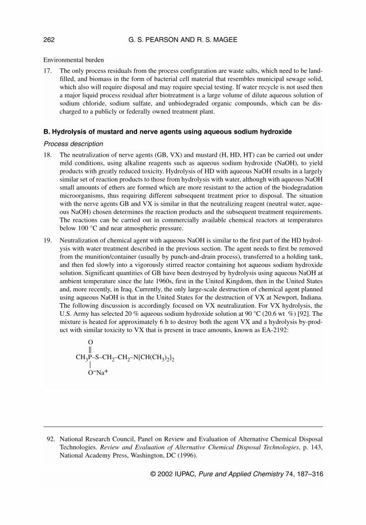
Environmental burden
17. The only process residuals from the process configuration are waste salts, which need to be land-filled, and biomass in the form of bacterial cell material that resembles municipal sewage solid,which also will require disposal and may require special testing. If water recycle is not used thena major liquid process residual after biotreatment is a large volume of dilute aqueous solution ofsodium chloride, sodium sulfate, and unbiodegraded organic compounds, which can be dis-charged to a publicly or federally owned treatment plant.
B. Hydrolysis of mustard and nerve agents using aqueous sodium hydroxide
Process description
18. The neutralization of nerve agents (GB, VX) and mustard (H, HD, HT) can be carried out undermild conditions, using alkaline reagents such as aqueous sodium hydroxide (NaOH), to yieldproducts with greatly reduced toxicity. Hydrolysis of HD with aqueous NaOH results in a largelysimilar set of reaction products to those from hydrolysis with water, although with aqueous NaOHsmall amounts of ethers are formed which are more resistant to the action of the biodegradationmicroorganisms, thus requiring different subsequent treatment prior to disposal. The situationwith the nerve agents GB and VX is similar in that the neutralizing reagent (neutral water, aque-ous NaOH) chosen determines the reaction products and the subsequent treatment requirements.The reactions can be carried out in commercially available chemical reactors at temperaturesbelow 100 °C and near atmospheric pressure.
19. Neutralization of chemical agent with aqueous NaOH is similar to the first part of the HD hydrol-ysis with water treatment described in the previous section. The agent needs to first be removedfrom the munition/container (usually by punch-and-drain process), transferred to a holding tank,and then fed slowly into a vigorously stirred reactor containing hot aqueous sodium hydroxidesolution. Significant quantities of GB have been destroyed by hydrolysis using aqueous NaOH atambient temperature since the late 1960s, first in the United Kingdom, then in the United Statesand, more recently, in Iraq. Currently, the only large-scale destruction of chemical agent plannedusing aqueous NaOH is that in the United States for the destruction of VX at Newport, Indiana.The following discussion is accordingly focused on VX neutralization. For VX hydrolysis, theU.S. Army has selected 20 % aqueous sodium hydroxide solution at 90 °C (20.6 wt %) [92]. Themixture is heated for approximately 6 h to destroy both the agent VX and a hydrolysis by-prod-uct with similar toxicity to VX that is present in trace amounts, known as EA-2192:
O||
CH3P–S–CH2–CH2–N[CH(CH3)2]2|O–Na+
G. S. PEARSON AND R. S. MAGEE
© 2002 IUPAC, Pure and Applied Chemistry 74, 187–316
262
92. National Research Council, Panel on Review and Evaluation of Alternative Chemical DisposalTechnologies. Review and Evaluation of Alternative Chemical Disposal Technologies, p. 143,National Academy Press, Washington, DC (1996).

Scientific principles
20. The neutralization processes evaluated for disposal of VX involve hydrolysis of the P–S bond[93], which is essential to the toxicity of this nerve agent. Figure 5 shows the reaction scheme forhydrolysis mediated by sodium hydroxide. The reaction with sodium hydroxide produces the rel-atively nontoxic ethyl methyl-phosphonic acid (EMPA), which is present as its sodium salt, andan aminothiol compound. The aminothiol, which has a very unpleasant odor but low toxicity, isoften referred to as “thiol”, and should not to be confused with methylmercaptan, which is alsoknown as “thiol”. Much the same reaction occurs during hydrolysis with neutral water, when theresulting EMPA is then present as the corresponding acid rather than the sodium salt.
21. A major advantage of the alkaline hydrolysis process became evident during neutralization stud-ies on impure munitions-grade VX that contained small amounts of a compound containing twoP–S bonds. This material (known as “VX-bis”) reacts with water to form EA-2192 (which is pres-ent as the sodium salt under alkaline conditions). EA-2192 is almost as toxic as VX itself and isresistant to further hydrolysis by water alone. The concentration of EA-2192 is low, but it con-tributes significantly to the toxicity of the hydrolysate. During hydrolysis mediated by sodiumhydroxide, EA-2192 is also hydrolyzed by an analogous reaction to form aminothiol and thesodium salt of methylphosphonic acid (MPA), which has low toxicity. At low temperatures (20 to25 °C), small quantities of EA-2192 may be present for a prolonged period owing to slow reac-tion rates. At higher temperatures (75 to 90 °C), both VX and EA-2192 hydrolyze at acceptablerates to form relatively nontoxic products. The alkaline hydrolysis of VX is exothermic, releas-ing 32.3 kcal/mole.
© 2002 IUPAC, Pure and Applied Chemistry 74, 187–316
Critical evaluation of proven chemical weapon destruction technologies 263
O O|| + NaOH ||
CH3P–S–CH2–CH2–N[CH(CH3)2]2 CH3P–O–Na+ + Na+ –S–CH2–CH2–N[CH(CH3)2]2| |O–CH2–CH3 O–CH2–CH3
VX EMPA Thiol
+ NaOH + NaOHslow
–CH3CH2OH –CH3CH2OH
O O|| + NaOH ||
CH3P–S–CH2–CH2–N[CH(CH3)2]2 CH3P–O–Na+ + Na+ –S–CH2–CH2–N[CH(CH3)2]2| |O–Na+ O–Na+
EA 2192 MPA Thiol
93. For further information on the chemistry associated with the detoxification of VX see Yu-ChuYang, “Chemical detoxification of nerve agent VX”, Acc. Chem. Res. 32, 109–115 (1999).
Fig. 5 Reaction scheme for neutralization of VX with sodium hydroxide.
Technology status
Alkaline hydrolysis
22. The neutralization technology chosen for destroying VX agent described above was developed bythe U.S. Army on the basis of previous experience and ongoing research. Although not much hasbeen reported about the alkaline hydrolysis of VX, sodium hydroxide has been used to destroyGB (sarin) nerve agent on a substantial scale. The experience gained from those operations facil-itated the development of a VX hydrolysis process in U.S. Army research carried out since 1993.
23. The VX neutralization process was developed utilizing a series of laboratory-scale reactors andthrough bench-scale testing in a 114-L (30-gal) stirred reactor. The bench-scale studies in Mettlerreactors yielded reliable data on heats of reaction and reaction rates. The tests monitored the dis-appearance of VX and of secondary products, such as EA-2192, as well as enabling the optimumconditions to be determined for the 114-L reactor. Five tests using the 114-L reactor eachdestroyed 25 to 30 kg of VX in a typical run, and neutralization of as much as 39.4 kg was demon-strated. More important, the effects of reaction times and mixing (e.g., stirring rate and the effectof adding a static mixer) were evaluated on a large enough scale to extrapolate to pilot- or pro-duction-scale reactors.
Stability, reliability, and robustness
24. The low-temperature, low-pressure, semibatch processing should be stable and reliable. Thehydrolysis reaction is mildly exothermic (heat-releasing), but the relatively low energy content ofthe hydrolysis mixture precludes uncontrolled or runaway reactions. The simple unit processesand standard equipment closely resemble well-tested counterparts in the chemical industry.
Monitoring
25. The hydrolysate from neutralization is analyzed for residual agent before it is released from thetoxics control area. Under current rules, a second step will be necessary to break the C–P bondbefore the waste can be considered as meeting the CWC requirements.
Safety considerations
Safety interlocks
26. The unit processes, such as ton-container processing and agent neutralization, operate independ-ently with interstage storage of the aqueous process stream. Therefore, only minimal interlocksare required.
Hazard inventory
27. The inherent hazard potential, except for the hazards associated with handling agent, is limitedbecause the aqueous streams are nonflammable and at low temperature and pressure. Thehydrolysate retains some non-agent toxicity. The process requires handling caustic sodiumhydroxide solutions, but the procedures for doing this are standard in the chemical industry.
Materials of construction
28. Materials of construction concerns should be similar to hydrolysis with neutral water and theirselection should not present serious problems.
Environmental impact
Test prior to release
29. The hydrolysate from the neutralization reactor can be tested for the presence of residual agentand for any toxic by-product (EA-2192) before release from the toxic control area. Processvapors, which are monitored for agent, can be scrubbed through a sodium hydroxide solution and
G. S. PEARSON AND R. S. MAGEE
© 2002 IUPAC, Pure and Applied Chemistry 74, 187–316
264

passed through carbon filters before release. Emptied munitions or storage containers can besteam-cleaned and tested for the presence of agent vapor before being shipped off site for disposalor reclamation.
Environmental burden
30. The hydrolysate from the neutralization reactor will require further treatment prior to dischargeto the environment. The major residuals are likely to include a liquid process stream and wastesalts.
C. Reaction of mustard and nerve agents using amines and other reagents
Process description
31. Mustard and nerve agents can be reacted with monoethanolamine, or in the case of VX withpotassium isobutylate (potassium 2-methyl-1-propoxide), at 100 °C under atmospheric pressurefor about an hour. The resulting reaction products then need to be disposed of in the second stageof the process. The second phase can involve incineration of the reaction products, or bitum-enization (mixing the reaction products with hot bitumen to produce monolithic bitumen blocksfor burial).
Scientific principles
32. Mustard is neutralized by monoethanolamine at 100 °C under atmospheric pressure to yield prod-ucts that include chloroethanol, monoethanolamine hydrochloride, water, and more complicatedorganic molecules.
S(CH2CH2Cl)2 + 3H2NCH2CH2OH = S(CH2CH2)2NCH2CH2OH + 2H2NCH2CH2OH.HCl
The reaction mass can then be incinerated or reacted with calcium hydroxide and bitumen to pro-duce insoluble calcium salts in the bitumen reaction mass.
33. The nerve agents GB or GD are neutralized by monoethanolamine at 100 °C under atmosphericpressure to yield, in the case of GB, isopropyl methylphosphonic acid and 2-aminoethylisopropylmethylphosphonate and, in the case of GD, the corresponding products.
O O|| ||
i-PrO–P–F + H2NCH2CH2OH = i-PrO–P–OCH2CH2NH2 + H2NCH2CH2OH.HF| |CH3 CH3
In the second stage, the reaction mass can then be incinerated or reacted with calcium hydroxideand bitumen at 200 °C under reduced pressure to form insoluble calcium methylphosphonate andother salts in the bitumen mass and to release ethanolamine and isopropyl alcohol in the case ofGB and the corresponding materials for GD.
34. The nerve agent VR (Russian VX) is neutralized using a decontamination solution known asRD-4, which contains potassium isobutylate dissolved in isobutanol and N-methylpyrrolidinone,at 90–95 °C under atmospheric pressure to break the P–S bond and yield diisobutyl methylphos-phonate and other products.
O O|| ||
i-BuO-P-SCH2CH2NEt2 + KO-i-Bu + i-BuOH = i-BuO-P-O-i-Bu + KSCH2CH2NEt2| |
CH3 CH3
© 2002 IUPAC, Pure and Applied Chemistry 74, 187–316
Critical evaluation of proven chemical weapon destruction technologies 265

In the second stage, the reaction mass can be incinerated or reacted with bitumen (without cal-cium hydroxide) at a temperature which is increased from 130–140 °C to about 180 °C underreduced pressure to form potassium methylphosphonate and other salts in the bitumen mass andto release isobutanol and N-methylpyrrolidinone.
Technology status
35. Neutralization of mustard and nerve agents using monoethanolamine has been used by Russia forseveral years in chemical weapon destruction applications. The KUASI mobile system isdesigned to destroy chemical munitions filled with GB, GD, and VR (Russian VX) but withoutexplosives. KUASI uses monoethanolamine (MEA) to neutralize GB, GD, and VR by heating to100 °C for 30 to 45 min followed by dilution with equal volume of water or alkali solution priorto transfer to a liquid-waste incinerator. The system has been used to destroy more than 4000munitions during the period 1980–1990 [94].
36. In a meeting in 1991, Russia reported [95] that it preferred a two-stage process in which GB, GD,and mustard are reacted with ethanolamine to produce a detoxified product which is then incin-erated. VR (Russian VX) is reacted with a 1:1 mixture of ethylene glycol and orthophosphoricacid before incineration. The processes are discontinuous with 1 h for reaction followed by a fur-ther 1.5 h for analysis to confirm the absence of any agent in the material to be incinerated.
37. The Russian preferred mustard destruction process involves the reaction of mustard with an equalweight of reagent, which is a 9:1 mixture of monoethanolamine and ethylene glycol [96].Reaction temperature is 100–110 °C for 1 h. The original intentions were to incinerate the reac-tion products, but incineration might produce dioxins and an alternative to incineration was there-fore sought. This led to the bitumenization solution in which tough road bitumen with a soften-ing temperature of 65–70 °C was used. The reaction products are processed in bitumen withcalcium hydroxide at 170 °C for 45 min producing bitumen masses with a softening temperatureof 81.5 °C, which enabled the masses to be formed into monolithic blocks for subsequent burial.
38. The preferred process for destruction of nerve agents consists of reacting GB and GD with a mix-ture of monoethanolamine and water followed by a second stage in which the reaction productsare combined with calcium hydroxide and bitumen [97]. The GB or GD is dissolved in industrial
G. S. PEARSON AND R. S. MAGEE
© 2002 IUPAC, Pure and Applied Chemistry 74, 187–316
266
94. R. G. Sutherland. “The destruction of old and obsolete chemical weapons: Past experience”, inThe Challenge of Old Chemical Munitions and Toxic Armament Wastes, T. Stock and K. Lohs(Eds.), SIPRI Chemical and Biological Warfare Studies, No. 16, p. 151, Oxford University Press(1997).
95. As described in R. G. Sutherland, “The destruction of old and obsolete chemical weapons: Pastexperience”, in The Challenge of Old Chemical Munitions and Toxic Armament Wastes, T. Stockand K. Lohs (Eds.), SIPRI Chemical and Biological Warfare Studies, No. 16, p. 151, OxfordUniversity Press (1997).
96. S. V. Petrov, V. I. Kholstov, V. P. Zoubrilin, N. V. Zavialova. “Practical actions of Russia on prepa-rations for destruction of stockpiled Lewisite and ‘mustard’”, in Arsenic and Old Mustard:Chemical Problems in the Destruction of Old Arsenical and ‘Mustard’ Munitions, J. F. Bunnettand M. Mikolajczyk (Eds.), NATO ASI Series, 1. Disarmament Technologies, Vol. 19, Kluwer,Dordrecht (1998).
97. Bonn International Center for Conversion & Stockholm International Peace Research Institute.Chemical Weapons Destruction in Russia (1996–97). Available at http://projects.sipri.se/cbw/research/sipri-bicc-cw-mainpage.html

grade ethanolamine, which contains around 20 % water, and the mixture heated to 110 °C for 1 hat atmospheric pressure. This treatment achieves a destruction removal efficiency of greater than99.9999 % with both GB and GD resulting in a reaction mass with a toxicity slightly greater thanthat of monoethanolamine. In the second stage, the reaction masses are combined with calciumhydroxide and bitumen and heated to about 200 °C under reduced pressure for 1 h. Under theseconditions, chemical reactions are expected to destroy any traces of GB or GD that remained afterthe monoethanolamine treatment. The alcohols released and any excess solvent ethanolamine aredistilled out of the bitumenization reaction mixture and are collected by condensers. At the endof the process, the liquid bitumen-salt mass is drained from the reactor and allowed to solidify.
39. For VR (Russian VX), the first step is to react the agent with a decontamination solution knownas RD-4, which contains potassium isobutylate dissolved in isobutanol and N-methylpyrrolidi-none, and the mixture heated at 90–95 °C for 30 min at atmospheric pressure. This treatmentachieves a destruction removal efficiency of greater than 99.9999 % resulting in a reaction masswith a toxicity comparable to that of the solvent isobutanol. In the second stage, bitumen, but inthis case without calcium hydroxide, is added to the reaction products. Over a period of 45 min,the reactor temperature is gradually increased from 130–140 °C to about 180 °C as the pressureabove the hot bitumen is slowly reduced to about 150 torr. Volatile constituents emitted are recov-ered in condensers and include isobutanol and N-methylpyrrolidinone.
40. The bitumenization product in both cases include methylphosphonate products which may beleached over time from the bitumen-salt mass, and will need to be taken into account in consid-ering disposal of the bitumen-salt masses. The amount of waste generated during the destructionprocess for GB and GD was 4 to 7 times the original amount destroyed while that generated dur-ing the VR destruction was approximately three times greater.
Safety considerations
41. The neutralization is carried out at about 100 °C under atmospheric pressure usingmonoethanolamine or decontamination solution RD-4, which does not present any unusual safetyconcerns. The second stage of bitumenization, although at slightly higher temperatures andreduced pressure, also does not present any unusual safety concerns.
Environmental impact
42. The principal concern relates to the bitumen mass produced from the reaction products of the neu-tralization and the extent to which some of the salts may be leached over time. This will need tobe considered in considering disposal of the bitumen mass.
D. Electrochemical oxidation
Process description
43. This is a patented process, known as Silver II, which was originally developed for destroying solidand liquid radioactive organic waste streams from a fast-reactor development program. Theprocess takes place in two separate 180-kW electrochemical cells which are connected in paral-lel through a 360-kW power cell. At the start of operation, the composition of the anolyte is anaqueous solution that is approximately 8 molar in nitric acid, 0.5 molar in silver nitrate, and 0.02to 0.03 molar in agent. The catholyte is an aqueous solution of 4 molar nitric acid.
44. When power is applied to the cell, Ag(I) ions are oxidized at the anode to the highly reactiveAg(II). The Ag(II) species have been shown to exist in the form of AgNO3
+ ions, which impart abrown color to the solution in the absence of organic materials. In the presence of organic sub-stances, AgNO3
+ ions oxidize water into intermediates such as hydroxyl radicals that rapidly oxi-
© 2002 IUPAC, Pure and Applied Chemistry 74, 187–316
Critical evaluation of proven chemical weapon destruction technologies 267

dize the organic species. Simultaneously, Ag(II) is reduced back to Ag(I), which migrates back tothe anode surface where it is reoxidized to Ag(II). Silver therefore serves as an electron-transferintermediate that is not consumed in the process. However, when chloride ions or organic chlo-rides are present, as in HD, Ag(I) precipitates as AgCl.
45. Some CO will form as well, by analogous reactions, but laboratory tests have shown that carbonis converted primarily to CO2. Hydrated protons (hydronium ions, H3O+) move across the mem-brane toward the cathode, where the primary reaction is reduction of nitric acid to nitrous acid:
HNO3 + 2H+ + 2e ⇒ HNO2 + H2O
The nitrous acid will partially decompose to NO gas, nitric acid, and water. In laboratory tests,the gas leaving the cathode compartment had the characteristic red-brown color of NO2, whichcan form by oxidation of NO in the gas phase when O2 is present. The reaction products are sub-sequently treated outside the electrochemical cell in order to reoxidize HNO2 to HNO3 and toneutralize the acids containing the sulfur, phosphorus, nitrogen, and chlorine components of theagent to their corresponding sodium salts (sodium sulfate, sodium phosphate, sodium nitrate, andsodium chloride).
46. The overall reactions are similar to the overall reactions for incineration of VX and HD, but theyoccur at low temperature (less than 90 °C) and close to atmospheric pressure. In the electro-chemical process, with both agents, carbon is released to the gas phase primarily as CO2, and thesulfur, phosphorus, and chlorine components of the agent appear in the final effluent as hydratedanions in aqueous solution with sodium being the principal cation. This solution can be analyzedand treated further, if necessary, prior to release.
47. Three additional reactions that can occur will affect the energy efficiency of the process. First,Ag(II) can react directly with water in the anode compartment to form oxygen gas (O2). Second,the Ag(I) can migrate across the membrane to the cathode compartment. Third, cationic impuri-ties, such as iron, copper, or mercury, in the agent can migrate across the membrane to the cath-ode compartment.
48. The process reactions involving agent cannot be reversed. Therefore, once agent is destroyed, itcannot reform. However, agent destruction is likely to proceed in several steps, some of whichmay produce volatile organic intermediates that will enter the gas phase and require further treat-ment. In laboratory tests, varying levels of alkyl nitrates were identified in the anolyte off-gas,which was mainly CO2. Nonvolatile organic intermediates that may also form will remain in theanode compartment and will ultimately undergo complete conversion to simpler inorganic prod-ucts, such as sulfate, phosphate, chloride, and CO2/CO.
Scientific principles
49. Ag(II) in an acidic medium is one of the most powerful oxidizing agents known. The standardreduction potential of the Ag(II)/Ag(I) couple is 1.98 V, whereas the standard reduction potentialof the O2/H2O couple is only 1.23 V in nitric acid. Several published studies [98] report on theuse of anodically generated Ag(II) to oxidize organic substances in an acid solution.
G. S. PEARSON AND R. S. MAGEE
© 2002 IUPAC, Pure and Applied Chemistry 74, 187–316
268
98. See references cited on p. 78 of National Research Council, Panel on Review and Evaluation ofAlternative Chemical Disposal Technologies, Review and Evaluation of Alternative ChemicalDisposal Technologies, National Academy Press, Washington, DC (1996).
50. The basic half cell reactions for the Silver II process are as follows:
Anode: 2Ag+ ⇒ 2Ag++ + 2e E° = –1.98 VCathode: HNO3 + 2H+ + 2e ⇒ HNO2 + H2O E° = +0.94 V
The net reaction is therefore:
2Ag+ + HNO3 + 2H+ ⇒ 2Ag++ + HNO2 + H2O E° = –1.04 V
In these equations, E° is the standard equilibrium potential at zero current flow when all reactantsand products are at unit activity. In practice, the required potential is larger than the standard equi-librium potential owing to ohmic heating and other effects. An applied potential of 2 V is typi-cally used.
51. Oxidation of Ag(I) to Ag(II) at the surface of a platinum anode is rapid, and the required over-potential is low: 120 mV at 5 kA/m2. The principal Ag(II) species formed is AgNO3
+, which hasa dark brown color. The color disappears almost instantaneously in the presence of organic sub-stances due to several complex reaction steps that result in the complete oxidation of the organicsubstances and the reduction of Ag(II) back to Ag(I). Silver is not consumed in the process butfunctions as a mediator between the electric power fed into the cell and the organic compoundsbeing destroyed.
52. The reaction mechanisms in silver-mediated electrochemical oxidation are not well understood,but are believed to involve highly reactive, short-lived species, including hydroxyl and other rad-icals. In a study [99] of the electrochemical oxidation of ethylene glycol and benzene by Ag(II),several relatively long-lived reaction intermediates were identified, but with sufficient time com-plete oxidation was achieved as evidenced by measurement of stoichiometric quantities of CO2in the final product.
Technology status
53. The Silver II process has yet to be operated on a commercial scale although the electrochemicalcell in the Silver II process is used commercially in the chlorine-alkali industry. The largest-scalepilot tests of the Silver II process have been conducted with 4-kW cells consisting of a singleanode-cathode pair. The most extensive tests have been conducted with spent tributyl phosphatedissolved in kerosene as the feed material. These tests, which were run continuously, 24 h per dayfor up to 14 days, destroyed a total of 150 L of the feed material. Laboratory tests have been suc-cessfully completed on 10-g batches of agent in a pilot plant constructed at DERA, Porton Down,UK, that is suitable for tests on 15-L batches of agent. All of the tests prior to start-up of thePorton Down plant had been conducted with only the electrochemical cell component of theagent-destruction system. The Porton Down facility also includes anolyte and catholyte feed cir-cuits, an anolyte off-gas condenser, a NOx reformer system, and a modified version of the com-bined off-gas treatment circuit, which culminates in a sodium hydroxide scrubber.
54. The NRC AltTech report [100] summarizes the results of a test conducted at Porton Down on14.62 kg of “as supplied VX”, which contained 12.7 kg of agent. The test consisted of a singlecontinuous run of 6.5 days. At the end of the run, no agent was detected in the catholyte or in theprocess residuals. The lower detection limits for VX were 7.6 mg/m3 in the anolyte, 9.2 mg/m3
© 2002 IUPAC, Pure and Applied Chemistry 74, 187–316
Critical evaluation of proven chemical weapon destruction technologies 269
99. J. C. Farmer et al. J. Electrochem. Soc. 139 (3), 654–662 (1992).100. National Research Council, Panel on Review and Evaluation of Alternative Chemical Disposal
Technologies. Review and Evaluation of Alternative Chemical Disposal Technologies, p. 79,National Academy Press, Washington, DC (1996).

in the catholyte, and 1.7 mg/m3 in the residuals discharged during the trial. The correspondingvolumes were 0.0724 m3 of anolyte, 0.0854 m3 of catholyte, and 0.0929 m3 of process residuals.The total residual VX was therefore less than 1.5 mg out of an input of 12.7 kg of VX, corre-sponding to an agent destruction efficiency of greater than 99.99998 %. The destruction efficiencyfor conversion of organic carbon to CO2 and CO was 88.7 %.
55. Additional bench-scale tests (1/35 full-scale) involved the treatment of 100 g of GB [101]. A 60-W cell was used, and small batches of material were added. The reaction time was 17 h, afterwhich the destruction efficiency was greater than 99.9999 % based on detection limits. The oxida-tion efficiency based on CO/CO2 in the off-gas as compared to the carbon feed was relatively poor(70 %). There was no measure of total hydrocarbons in the off-gas. Energetic materials were testedin an isolation laboratory with a 20 % slurry of energetic material in water. Separate runs were con-ducted with 100 g of TNT in the form of fine particles, 100 g of RDX, 100 g of tetryl, and 100 gof double-base propellant. In two tests, the TNT slurry was run for 42 h, after which TNT wasbelow detection limits, corresponding to a destruction efficiency of greater than 99.9999 %.
Stability, reliability, and robustness
56. The agent destruction process operates at low temperatures and atmospheric pressure. Theprocesses in the unit operations of the system are not sensitive to small excursions in compositionor temperature. Rapid or runaway changes that might create emergency conditions are highlyunlikely. Therefore, the response time required for control instrumentation is not very demand-ing. However, the reaction rates and processes are sensitive to temperature, which can be difficultto control at larger scales, and it may be difficult to control to prevent localized boiling in thecells. The design temperature for the process is 90 °C. Portions of the process are exposed to highelectric currents that can raise temperatures, however, and any blockage that restricts flow couldresult in localized boiling. This difficulty would add complexity to scale-up.
57. The NRC report [102] indicated several concerns about the ability of the process to handle nonop-timal feed streams and especially (1) the potential for plugging caused by the accumulation ofsolids; (2) the effects of metals on the electrolytic reaction efficiency; and (3) the reaction of nitricacid with organic substances in the feed. Until these issues have been thoroughly investigated, therobustness of the process was considered questionable.
Monitoring and control
58. The monitoring and control system involves a relatively straightforward application of normalindustrial techniques. The transducers for temperature, pressure, flow, and liquid level are com-mercially available. A centralized computer is used to achieve automatic closed-loop control viacontrol algorithms and operator interface. The complexity of the control systems is consistentwith the chemical process plants in general. There is, however, some uncertainty as to how holesin cell membranes might be detected.
G. S. PEARSON AND R. S. MAGEE
© 2002 IUPAC, Pure and Applied Chemistry 74, 187–316
270
101. National Research Council, Committee on Review and Evaluation of Alternative Technologiesfor Demilitarization of Assembled Chemical Weapons. Review and Evaluation of AlternativeTechnologies for Demilitarization of Assembled Chemical Weapons, pp. 50–51, NationalAcademy Press, Washington, DC (1999).
102. National Research Council, Committee on Review and Evaluation of Alternative Technologiesfor Demilitarization of Assembled Chemical Weapons, Review and Evaluation of AlternativeTechnologies for Demilitarization of Assembled Chemical Weapons, pp. 51–52, NationalAcademy Press, Washington, DC (1999).

Safety considerations
Safety interlocks
59. The electrochemical oxidation process consists of several unit operations, but these do not haveto be tightly integrated. Temperature, pressure, and chemical concentrations are monitoredclosely. If the monitoring data signal a malfunction, the cell current can be rapidly shut down.Once the problem causing the malfunction has been found and corrected, restarting the process isstraightforward.
Hazard inventory
60. The Silver II processes operate at the relatively low temperature of 90 °C and low pressure (essen-tially atmospheric pressure), this minimizing stored energy and reducing process hazards. Nitricacid concentrations are expected to be within safe operating ranges of 4 to 12 molar for anolyteand 2 to 6 molar for catholyte.
61. The agent feed rate of about 0.01 m3/h for each 180-kW cell implies that 12.7 kg/h of mustard isadded to each cell or 10 kg/h of VX. Because the agent will be rapidly hydrolyzed by the con-centrated nitric acid, the inventory of agent in the anolyte circuit at any given time would be farless than 12.5 kg (equivalent to 5000 ppm in a 2.5 m3 anolyte volume).
62. The process requires the handling of highly corrosive or reactive materials such as nitric acid,concentrated sodium hydroxide solutions, hydrogen peroxide, and 90 % oxygen gas. Nitric acidhas been described as the common chemical most frequently involved in reactive incidents owingto its exceptional ability to function as an effective oxidant even when fairly dilute or at ambientpressure. Many reported incidents have involved closed or nearly closed vessels that have failedfrom internal gas pressure created either by oxidation of organic compounds to CO2 or auto-decomposition of nitric acid to NOx fumes and oxygen. Such incidents are unlikely in the SilverII process because the system is essentially open and the concentration of organic substances incontact with nitric acid is low. Worker-safety training and chemical containment are therefore par-ticular concerns, but harmful releases to the surrounding community are unlikely.
Environmental impact
Test runs prior to release
63. All liquid and solid reaction products can be tested prior to release. Gaseous products are nottested prior to release but are treated extensively to ensure the removal of any agent and of volatileorganic contaminants formed in the electrochemical cell. Moreover, reaction conditions such astemperature, pressure, and the basic reaction mechanism ensure very low concentrations of agentand other organic substances in the feed to the gas cleaning system. The off-gas circuit can bemodified to accommodate hold-and-test prior to release, if that is required.
Environmental burden
64. The major liquid process residual is an aqueous solution of common salts: sodium chloride,sodium sulfate, sodium phosphate, and sodium nitrate. The solution will contain silver at a con-centration below the applicable regulatory standards in many countries.
65. Gaseous effluents are anticipated to be primarily CO2, O2, and N2.
© 2002 IUPAC, Pure and Applied Chemistry 74, 187–316
Critical evaluation of proven chemical weapon destruction technologies 271

E. Solvated electron technology (SET)
66. Solvated electron technology (SET) can be used to destroy chemical agents, deactivate energeticmaterials, and decontaminate metal parts and dunnage. SET solutions of metallic sodium in anhy-drous liquid ammonia are highly reducing and are characterized by an intense blue color from thepresence of partially solvated (i.e., ammoniated) electrons. The blue color provides a visual indi-cator of the reactivity of the solution for destroying agents and energetics. The solid and liquidresiduals of the SET process are hydrated with water to destroy the excess sodium. The hydrationproducts from agent and energetics destruction is further treated by oxidation with sodium per-sulfate or hydrogen peroxide. Teledyne Commodore has proposed a technology package for thedestruction of assembled chemical weapons based on SET [103].
Process description
67. The proposed disassembly processes differ significantly from the U.S. Army baseline incinera-tion system as used at JACADS and TOCDF principally in the use of ammonia-jet cutting andammonia wash-out. In both the cutting and wash-out operations, ammonia is pressurized to 2720atm by an intensifier pump and delivered to the work area through a 0.25-mm-diameter orifice atvelocities of about 1000 m/s. Pre-intensifier boost pumps are used to ensure adequate pressureand volume of ammonia and prevent flashing of the liquid into gas during the suction stroke ofthe intensifier. For the cutting operation, 180-micron abrasive particles, normally of garnet, areadded to the pressurized ammonia stream through a stainless steel venturi mixing section. A pres-sure vessel surrounds the cutting and wash-out processing equipment, providing an intermediatechamber that is maintained at 10.5 atm inside a U.S. Army baseline explosion-containment room.The pressurized fluid from the intensifier pump is passed through a chiller to reduce the temper-ature of the liquid significantly below room temperature because prechilling is reported toenhance the jet cutting properties of the liquid ammonia.
68. An SET solution is generated by mixing liquid sodium and liquid ammonia to form a 4 % solu-tion of sodium in liquid ammonia. The sodium is transferred at its melting point of 97.5 °C; theliquid ammonia is transferred at room temperature and 10.5 atm (saturated conditions) and thetwo reagents combined in an in-line static mixer. The prepared SET solution is fed to a static reac-tor mixer, and agent from the feed vessel is introduced below the liquid surface. The reaction iscarried out at temperatures of 19 to 23 °C and pressures of 8.5 to 12.4 atm. The agent destructionreactions are exothermic, and temperature is controlled by evaporation of ammonia. The evapo-rated ammonia and off-gases from the SET reaction are collected in holding tanks for testing priorto venting to the gas-treatment train. The slurry from the SET reaction, still at elevated pressure,is treated with water to destroy the excess sodium. The resultant suspension is transferred at ele-vated pressure to a centrifuge where liquids and solids are separated. The solids are transferred toa carbon steel vessel and mixed with water. The solution is then oxidized with sodium persulfate.The liquids remaining in the centrifuge are mixed with water and fed to the bottom of an ammo-nia-recovery tower.
69. The slurry produced from the wash-out of energetic material is collected in a carbon steel vessel,diluted with ammonia to a standard composition and mixed with a solution of sodium in liquidammonia in a reaction vessel. Munitions metals are shredded and transferred to a metal SET reac-tor for treatment. Agent-contaminated dunnage is decontaminated in SET solution. The technol-ogy approach is summarized in the table.
G. S. PEARSON AND R. S. MAGEE
© 2002 IUPAC, Pure and Applied Chemistry 74, 187–316
272
103. National Research Council, Review and Evaluation of Alternative Technologies forDemilitarization of Assembled Chemical Weapons, National Academy Press, Washington, DC(1999).

Major demilitarization operation Approach(es)
Disassembly of munitions High-pressure ammonia fluidized jet cutting and ammonia-jet wash-out.
Treatment of chemical agent SET reduction; hydration of the condensed-phase products; oxida-tion of the hydrolysate with sodium persulfate or hydrogen peroxide.
Treatment of energetics SET reduction; hydration of the condensed-phase products; oxida-tion of the hydrolysate with sodium persulfate or hydrogen peroxide.
Treatment of metal parts Agitation of shredded parts in SET solution to a 3X conditiona
Treatment of dunnage Grinding or shredding; mixing with SET solution to destroy agent.Disposal of waste Solids. Product from process and decontaminated dunnage sent to
a suitable permitted landfill; metal parts shipped to Rock Island Arsenal for 5X treatment.
Liquids. Stabilized with cement and shipped to appropriately per-mitted landfill; oil and hydraulic fluids sent to a TSDF (treatment, storage, or disposal facility).
Gases. Off-gases from process and vaporized hydrocarbon residu-als burned in boiler.
aAt the 3X decontamination level, solids are decontaminated to the point that the agent concentration in the head spaceabove the encapsulated solid does not exceed the health-based, 8-h, time-weighted average limit for worker exposure.Materials classified as 3X may be handled by qualified plant workers using appropriate procedures but are not releasableto the environment or for general public reuse. In specific cases in which approval has been granted, a 3X material maybe shipped to an approved hazardous waste treatment facility for disposal in a landfill or for further treatment.
Scientific principles
70. Although reactions of organic substances with solutions of metallic sodium in liquid ammoniahave been studied since 1865, the reaction products depend on the type of organic substance beingreacted. In general, the solvated electrons are attracted to the polar bond between carbon and amore electronegative species such as chlorine, fluorine, phosphorus, sulfur, or oxygen. The resultis cleavage of the covalent bond. The strongly electronegative species leaves as an anion. Thecomplementary site on the less electronegative atom, usually carbon, may capture a second elec-tron, thereby becoming negative; or the bonds in the remaining carbon skeleton may rearrangethemselves and release a gaseous alkane or alkene. Further reaction occurs when the condensedphase products of the SET reaction are hydrolyzed.
71. The experimental results from treating chemical agents in the laboratory are described below:
Agent HD (mustard). The expected initial reaction of mustard in the SET process is cleavage ofthe carbon–chlorine and of the carbon–sulfur bond by a solvated electron to form sodium chlo-ride and sodium sulfide. Gaseous ammonia released in the SET reaction results from evaporation,which is used to control the temperature of the liquid mixture. Teledyne-Commodore, who wasdeveloping the technology, was unable to determine the molecular composition of the slurry fromthe SET reaction prior to hydration because of analytical difficulties.
Agent GB. The expected initial reaction of GB in the SET process is cleavage of the phospho-rus–fluorine bond by a solvated electron to form sodium fluoride. Release of ammonia gas in theSET reaction again results from evaporation used for temperature control. The composition of theslurry from the SET reaction was not analyzed prior to hydration. In small-scale tests, GB wasnot detectable in any of the reaction products.
Agent VX. Unlike mustard and GB, the VX molecule does not have strongly polar bond for thesolvated electrons to attack. Teledyne-Commodore postulates that cleavage occurs initially at the
© 2002 IUPAC, Pure and Applied Chemistry 74, 187–316
Critical evaluation of proven chemical weapon destruction technologies 273
phosphorus–sulfur bond, the carbon–sulfur bond, or at both simultaneously. Ammonia is vapor-ized during the SET reaction. The composition of the slurry from the SET reaction was not ana-lyzed prior to hydration.
Technology status
72. Teledyne-Commodore proposes a disassembly process based on ammonia-jet cutting. They sug-gest several advantages of ammonia over water as many of the hazardous materials that arewashed out of munitions have very low solubility in water and contain surfactants that aid in theformation of stable aqueous emulsions which present serious safety and maintenance problems infull-scale conventional-munition disassembly facilities. Anhydrous ammonia, in contrast, dis-solves most of the explosive materials and forms nondetonable solutions. Teledyne-Commodorehave successfully demonstrated ammonia-jet cutting at Redstone Arsenal on M60 (inert) and M61(live) rockets, a 4.2-inch inert mortar, and a 105-mm M60 inert projective. Successful wash-outof Comp B high explosive and M28 propellant was demonstrated during the M61 test series.Teledyne-Commodore claims that ammonia-jet cutting is 25 % faster than water-jet cutting.
73. Chemical agent destruction tests using SET have been conducted by Teledyne-Commodore. Thelargest quantities of agent tested in a single batch were 0.64 kg of HD, 0.45 kg of HT, 0.45 kg ofVX, and 0.59 kg of GB. The concentration of agent in the SET solution after completion of thelaboratory tests was below detection limits in all cases (less than 200 ppb for HD and HT; andless than 20 ppb for VX and GB). This has demonstrated that the SET process, followed by hydra-tion, can destroy chemical agents to a destruction efficiency of at least 99.9999 %. However, con-siderably more testing and analysis will be required to determine the exact molecular composi-tion, phase distribution, and quantity of reaction products. This lack of information compoundsthe difficulty of developing optimum conditions for the final oxidation step.
74. The capacity of the SET process, followed by hydration, to decompose the energetic materials hasyet to be demonstrated. In laboratory experiments, the condensed-phase products were generallypasty, difficult to handle, of unknown polymeric composition, and sensitive to electrostatic igni-tion. Moreover, the reaction products identified represented less than 1 wt % of the materialtreated. In several instances, apparently spontaneous exothermic reactions occurred and the rootcauses of the exotherms have yet to be identified.
75. The SET/hydration products from the treatment of GB and VX include Schedule 2 chemicals thatmust be further treated. Teledyne-Commodore has tested sodium persulfate oxidation as themethod of secondary treatment, but only on a laboratory scale. A substantial amount of additionaltesting will be needed to validate the process and determine optimum conditions for full-scaleoperation. In the few laboratory tests that were completed, the reactions were highly exothermicand led to bubbling and rapid rises in temperature. To maintain the temperature in the range of 90to 100 °C, the sodium persulfate solution had to be added in extremely small increments, whichincreased the reaction time.
76. No standard generally acceptable sampling and analysis methods are available for systems basedon liquid ammonia. The condensed phase products of SET can only be analyzed for specific chem-ical components after hydration. The hydration process changes the composition of the SET prod-ucts, in addition to converting excess sodium to sodium hydroxide and producing hydrogen gas.
77. There have been no full-scale applications of the technology package discussed above. The sys-tem is complex and has never been operated as a totally integrated package that includes oxida-tion. The system involves at least 16 unit operations. Five are for SET treatment of agents, ener-getics, shredded dunnage, metal parts and fuzes; the other eleven are for hydration of agents andenergetics, fluid-jet cutting, oxidation of energetic residue, oxidation of agent residue, evapora-
G. S. PEARSON AND R. S. MAGEE
© 2002 IUPAC, Pure and Applied Chemistry 74, 187–316
274

tion of oxidized residues, recovery of ammonia, stabilization of oxidized residues in cement, det-onation of fuzes, decontamination of abrasives, and stabilization of fuzes/abrasives.
78. The SET process appears to be capable of destroying agents with a wide range of feedstock com-positions, temperature, and pressures. The reaction seems to be most sensitive to the sodium/feed-stock ratio, which must be high enough to ensure complete reaction. However, the capability ofthe SET/hydration process to deactivate energetics does not appear to be satisfactory, and opti-mum operating conditions have not been established. Teledyne-Commodore uses conductivity asthe main indicator that the reaction is complete. However, because some of the products of theSET reaction contribute to conductivity, additional control algorithms are being developed thatincorporate temperature, pressure, and feed composition.
Safety considerations
79. The SET process operates at ambient temperatures, using evaporation of ammonia to remove heatfrom the mildly exothermic reactions between the SET solution and the agent and energetics intheir respective reactors. Pressures as high as 2720 atm are used for the ammonia-jet cutting solu-tion during disassembly operations. With the exception of the small section of piping and theintensifier pump for the fluid-cutting solution, most of the systems operate at near atmosphericpressure to 10.5 atm. Where liquid ammonia is used, vessels will be operated at approximately10.5 atm pressure which is the vapor pressure of ammonia at typical ambient temperatures.
80. The Teledyne-Commodore technology package is basically an adaptation of existing technologiesused for the destruction of conventional munitions and other hazardous chemicals. Assumingcareful design and operation, the general technology of fluid-cutting and fluid wash-out shouldachieve acceptable worker-safety levels.
81. A particular aspect of the technology from the standpoint of worker safety is the hazard associ-ated with the primary chemicals used to destroy the agent and energetics. Liquid anhydrousammonia boils at –33.4 °C and becomes a toxic gas capable of burning in air. Liquid sodium(melting point 98 °C) is a reactive and pyrophoric metal that burns violently upon exposure to airor other oxidizing media and requires special firefighting methods and materials. Sodium persul-fate and hydrogen peroxide solutions are reactive chemical oxidizers as well as health hazards.
82. Although all of these chemicals are widely used in industry and releases and accidents are infre-quent, because of the hazardous and reactive nature of these chemicals, the SET systems must becarefully designed to ensure worker safety from, for example, toxic gas exposures and fires. Thisincludes minimizing the occasion when workers are in contact with the areas in which these haz-ardous chemicals may be present.
Environmental impact
83. Teledyne-Commodore has not characterized the effluents from their total system in sufficientdetail to assess the potential impacts on human health and the environment. The chemical com-position of the products of final oxidation is unknown, and the oxidation processes themselves arestill under development. It has been demonstrated that agent is unlikely to be present in any of theprocess effluents but the absence of other chemical compounds of concern has not been shown.In addition, the persulfate oxidation process results in a heavy burden of sodium sulfate arisingfrom the sodium persulfate and this may be difficult to stabilize for disposal [104].
© 2002 IUPAC, Pure and Applied Chemistry 74, 187–316
Critical evaluation of proven chemical weapon destruction technologies 275
104. U.S. Army Non-Stockpile Chemical Materiel Project. Technology Evaluation Panel Report:Evaluation of Neutralent Post-Treatment Technologies for the Non-Stockpile Chemical MaterielProgram, 18 September 2000, pp. 9–4. Available at http://www-pmcd.apgea.army.mil/nscmp/ip/r/tepoct00/index.asp

VIII. EFFLUENT TREATMENT
1. All the technologies used for chemical weapon destruction result in effluent streams—gas, liquid,and solid—which need to be treated to ensure that any toxic chemicals that are formed as a resultof the agent destruction process are destroyed and any remaining trace contaminants are at accept-able levels, which comply with national standards for release of the effluent stream into the envi-ronment, for recycling, for commercial use, or to a landfill. Attention is given in this section totreatment of gas, liquid, and solid effluent.
A. Gas
2. The appropriate approach to be taken for air pollution control depends on the nature of thedestruction process, the nature of the effluent, and the national regulations governing release tothe atmosphere. The principal air pollution control devices currently being used in waste destruc-tion facilities include liquid scrubbers using packed towers, spray dryers, dry scrubbers forgaseous pollutant control, wet or dry electrostatic precipitators, HEPA filters for particulate con-trol, and reactive carbon filters.
3. As chemical weapons are organic chemicals containing various heteroatoms such as chlorine, flu-orine, sulfur, oxygen, phosphorus, and nitrogen, their destruction through incineration results pri-marily in carbon dioxide and water along with products containing the heteroatoms as well asproducts of incomplete reaction. The efficiency of the agent destruction process is designed to bevery high and to exceed a destruction efficiency of greater than 99.9999 %; the residual amountof the original agent will be very small. Nevertheless, the effluent treatment scheme is designedto remove any trace amounts of agent remaining after the destruction process, along with theproducts of destruction.
4. The approaches to be taken to treat effluent are designed to meet the national standards and reg-ulations governing emissions, which initially were introduced because of widespread interna-tional concerns about emissions of dioxins and acid gases. As national standards and regulationsvary widely, this report considers, as an example, the standards required in the United States, asthere has been more work carried out in the United States than anywhere else to dispose of chem-ical weapons [105]. The key regulatory provisions in the United States are the following:
• Resource Conservation and Recovery Act (RCRA), 1976
• Toxic Substances Control Act (TSCA), 1976
• Clean Air Act, 1977
• Clean Water Act, 1977
• Regulations covering boilers and industrial furnaces that burn industrial waste, 1991
G. S. PEARSON AND R. S. MAGEE
© 2002 IUPAC, Pure and Applied Chemistry 74, 187–316
276
105. National Research Council, Committee on Demilitarizing Chemical Munitions and Agents.Disposal of Chemical Munitions and Agents, Appendix E, pp. 185–189, National Academy Press,Washington, DC (1984); National Research Council, Committee on Review and Evaluation of theArmy Chemical Stockpile Disposal Program. Recommendations for the Disposal of ChemicalAgents and Munitions, pp. 58–60, National Academy Press, Washington, DC (1994); NationalResearch Council, Committee on Review and Evaluation of the Army Chemical StockpileDisposal Program. Carbon Filtration for Reducing Emissions from Chemical Agent Incineration,pp. 11–12, National Academy Press, Washington, DC (1999).

The U.S. Environmental Protection Agency (EPA) under the RCRA establishes limits on thequantity of agent that may be permitted in an emission; stricter limits may be imposed by someState regulations. In addition, RCRA regulates more typical products of combustion which can bemonitored on a more or less continuous basis, such as carbon monoxide (CO), that may contributeto general pollution or be indicative of incomplete agent destruction. It also sets detailed limits onoperating conditions and metal emissions as well as requiring a program to reduce the volume orquantity and toxicity of the hazardous waste generated and shipped off site. TSCA regulates theincineration of PCBs. The Clean Air Act requires U.S. plants to obtain permits for regulated airemissions. More recently, regulations covering boilers and industrial furnaces that burn hazardouswaste were adopted in 1991, which set maximum allowable concentrations for a wide range oftrace organic and inorganic compounds in ambient air. In 1995, the Clean Air Act set standardsfor maximum achievable emissions control technology for municipal waste combustors thatincinerate more than 250 tons a day. These standards apply to dioxin emissions and to emissionsof mercury, lead, cadmium, arsenic, beryllium, and chromium. These controls are intended tolimit emissions to levels that are unlikely to harm human health or the environment. It should benoted, however, that public perceptions sometimes cause regulatory agencies to adopt even loweremission standards. Shortly, the United States will require all incinerators to employ theMaximum Achievable Control Technology (MACT).
5. Within the European Union, the approach has been to adopt the Best Available Techniques NotEntailing Excessive Cost (BATNEEC) and the Best Practical Environmental Option (BPEO) asthe principles upon which the environmental standards are being based [106]. Whereas targets areset for major pollutants, the operators of plants producing such pollutants are required to employthe BATNEEC principle. They also have to consider the impact of their processes across the entireenvironmental spectrum—air, water, and land—and apply the BPEO principle to determine thebest overall environmental option.
Acid scrubber
6. Packed towers are usually used to remove acid vapors such as hydrogen chloride. Typically, thepacked towers are vertical columns that have been filled with packing to provide a large surfacearea. The absorbing liquid is distributed over and trickles down through the packed bed, thusexposing a large liquid surface area. The gas stream, containing pollutants such as hydrogen chlo-ride, moves upward through the packed bed countercurrent to the absorbing liquid. Although theabsorbing liquid is usually water, other aqueous chemical solutions such as caustic soda or limeslurry may be used, thereby enhancing the absorption as the pollutants then react chemically withthe absorbing solution. For example, hydrogen chloride would react with caustic soda to producesodium chloride. The resulting liquid stream containing the absorbed pollutant then needs to betreated as a liquid effluent.
7. Dry and semidry scrubbers are also being introduced as flue-gas cleaning systems. Dry scrubbinginvolves the injection of a solid powder absorbent, such as lime or sodium bicarbonate, into theflue gas. Acid gas removal occurs in the dust collector as absorbent and ash particles and con-densed volatile matter are captured. In semidry processes, also known as spray drying, theabsorbent enters the flue gas with sufficient moisture to promote rapid absorption of acid gases,yet can be rapidly evaporated leaving solid particles prior to entering the collection system. Spray
© 2002 IUPAC, Pure and Applied Chemistry 74, 187–316
Critical evaluation of proven chemical weapon destruction technologies 277
106. R. G. Manley. “Chemical weapon agent and historic chemical munitions disposal: The Britishexperience”, in The Challenge of Old Chemical Weapons and Toxic Armament Wastes, T. Stockand K. Lohs (Eds.), Stockholm International Peace Research Institute, Oxford University Press(1997).

dryer absorbers are large cylindrical chambers into which a finely atomized absorbent, typicallya lime slurry, is sprayed into the gas stream containing acid gases. The acid gases react with atom-ized slurry droplets and form solid reaction products, such as calcium chloride. The emerging gasstream is usually sent to a high-efficiency particulate collector such as a fabric filter or dry elec-trostatic precipitator.
Particulate removal
8. Particulate removal is usually accomplished by wet scrubbers, electrostatic precipitators, or fab-ric filters. A small droplet diameter and high relative velocity between the particle and waterdroplet are required in conventional wet scrubbers in order to achieve a high-particulate collec-tion efficiency. In a venturi scrubber, this is achieved by introducing the scrubbing liquid at anangle to a high-velocity gas flow in the venturi throat. Water is typically injected into the venturiin quantities ranging from 22 to 55 L per 285 hL of gas. Very small water droplets are formed,and high relative velocities maintained until the droplets are accelerated to their terminal veloc-ity. Gas velocities through the venturi throat typically range from 60 to 160 m/s. The velocity ofthe gases causes atomization of the liquid, and the particulate is encapsulated by the droplets. Theenergy expended in the scrubber is accounted for by the pressure drop of the gas stream in thescrubber. Particulate collection efficiency is directly proportional to this gas stream pressure drop.The venturi itself needs to be followed by a separating section for the elimination of entraineddroplets from the flue gas.
9. An electrostatic precipitator requires that an electric charge be induced on the particulates bymeans of a discharge electrode system, thereby forcing the charged particles to accumulate on theoppositely charged collection plate system. From time to time, the collected particles must beshaken or knocked off the plates in a dry electrostatic precipitator. In a wet system, the collectedparticulate matter is washed continuously off the plates by a thin film of water flowing over theplates.
10. Fabric filter dust collectors are among the oldest and most widely applied high-efficiency partic-ulate emission control devices. The universal principle of operation is the removal of particulatesfrom particulate-laden gas by passing the gas through a filtration medium, normally a fabric. Thecleaned gas emerges from one side of the filtration medium, while the particulate is collected ontothe other side. Subsequently, the collected particulates are removed from the fabric. The fabric fil-ter is often used as a particulate control device with spray dryer acid scrubbers, although electro-static precipitators can also be used either instead of or in series with the fabric filter.
Activated carbon filters
11. Activated carbon bed filters are widely used in the chemical industry to recover low-concentra-tion chemicals from dilute gas streams and are also used to control volatile organic emissionsfrom production processes. In the mid-1980s, carbon bed filters were used to clean up effluent-gas streams from coal-fired utility boilers, hazardous waste incinerators, and municipal wasteincinerators [107]. Carbon bed filters not only remove gaseous pollutants, they also act as a filterto remove particulates. The available data from carbon bed filters used on incinerators in Europehas shown that emissions of particulates, acid gases (hydrogen chloride and sulfur dioxide), mer-cury, and dioxins and furans were reduced to levels near or below detection limits.
G. S. PEARSON AND R. S. MAGEE
© 2002 IUPAC, Pure and Applied Chemistry 74, 187–316
278
107. National Research Council, Committee on Review and Evaluation of the Army ChemicalStockpile Disposal Program. Carbon Filtration for reducing Emissions from Chemical AgentIncineration, Appendix C, pp. 70–71, National Academy Press, Washington, DC (1999).

Pollution abatement system
12. It is useful to consider how the gaseous effluent may be treated prior to release by considering theU.S. baseline incineration process. In this, the effluent from the liquid incinerator, the deactiva-tion furnace system, and the metal parts furnace goes to identical and dedicated separate pollu-tion abatement systems for the removal of gaseous pollutants and particles to meet emission stan-dards. Each pollution abatement system (see Fig. 6) consists of a quench tower, a venturiscrubber, a packed-bed scrubber, a mist-eliminator vessel, and an induced draft blower [108].
The exhaust gas enters the quench tower near the bottom, where it is cooled by contact with acountercurrent spray of caustic brine containing sodium hydroxide with a pH at above 8 or 9pumped from the packed-bed scrubber pump. Acidic gases (such as hydrogen chloride, hydrogenfluoride, nitrogen oxides, carbon dioxide, and sulfur dioxide, depending on the chemical agentbeing destroyed) in the exhaust gas react with caustic brine to form salts, which remain in solu-tion in the brine. The cooled gas stream exits from the top of the quench tower and enters a vari-able-throat venturi where it is scrubbed to remove particulates. The venturi uses a variable throatto maintain a constant pressure drop independent of the flow of exhaust gases. The brine streamsfrom the quench and the venturi scrubber are returned to the scrubber tower sump. An 18 %sodium hydroxide solution is added as necessary to maintain the brine pH at above 8 or 9.
13. The exhaust gas stream from the venturi scrubber enters the packed-bed scrubber tower below theclear liquor reservoir tray, moves upward through the packed-bed section, and exits at the top ofthe tower, after passing through a mist-eliminator pad. In the packed-bed section, the gas streamcomes in contact with a brine solution flowing concurrently through the bed. Acidic gases in theexhaust gas stream are further scrubbed with caustic brine. The brine solution from the packed-
© 2002 IUPAC, Pure and Applied Chemistry 74, 187–316
Critical evaluation of proven chemical weapon destruction technologies 279
Fig. 6 Pollution abatement system.
108. National Research Council, Committee on Review and Evaluation of the Army ChemicalStockpile Disposal Program. Review of Systemization of the Tooele Chemical Agent DisposalFacility, pp. 93–94, National Academy Press, Washington, DC (1996).

bed section falls back into the reservoir tray and is recycled back to the top of the packed-bed sec-tion. Excess brine overflows into the tower sump.
14. The scrubbed gases then enter a candle mist-eliminator vessel. Mist-eliminator candles—candle-shaped fabric filters—remove very fine mist and submicron particulate matter that was notremoved in the venturi scrubber. The cooled and cleaned exhaust gases are pulled through aninduced draft blower located upstream of the stack shared by the three pollution abatement sys-tems. In tests carried out at JACADS, particulate emissions from the three disposal furnaces wereconsistently low. The mean particulate concentration for all trial burns was less than 5mg/m3—well below the permitted level of 180 mg/m3. In a later report [109], it is stated that the JACADSand TOCDF incineration systems have been extensively tested, and the results have consistentlyshown that emissions regulated under the Clean Air Act, as well as trace emittants, are either thelowest or among the lowest in the EPA’s Hazardous Combustor Waste Emissions Database.
B. Liquid
15. Agent oxidation produces water along with other products. In addition, water is used in variousstages in the baseline process, as well as in the pollution abatement system in the U.S. baselineincineration technology. Designs for zero liquid water discharge are increasingly being adopted forindustrial plants that work with hazardous chemicals. This is also the case in the baseline incinera-tion technology where water discharge as vapor in the flue gas makes liquid water recycling unnec-essary. In some of the alternative technologies, such as neutralization, there are significant quanti-ties of water used necessitating treatment. There are three such techniques considered here:
I. Supercritical water oxidation (SCWO)
II. Biodegradation
III. Advanced oxidation processes (AOP)
Each is considered in turn.
I. Supercritical water oxidation (SCWO)
Process description
16. Chemical agents can be disposed of with technologies based on chemical neutralization. Thisdestruction process results in the production of a solution called “hydrolysate” that retains someundesirable characteristics and requires further treatment in order to comply fully with therequirements of the CWC. The composition and potentially viable treatment alternatives for eachhydrolysate varies based on the type of agent and the neutralization process selected. Supercriticalwater oxidation (SCWO), while technically viable for the destruction of neat agent, is also appro-priate for the further treatment of hydrolysate to meet the requirements for safe aid environmen-tally acceptable disposal. SCWO has been selected for the treatment of the hydrolysate from thenerve agent VX stored at the Newport, Indiana storage site [110]. The SCWO system is ahydrothermal process for the oxidation of hydrolysate that yields a wastewater stream and salts.
G. S. PEARSON AND R. S. MAGEE
© 2002 IUPAC, Pure and Applied Chemistry 74, 187–316
280
109. National Research Council, Committee on Review and Evaluation of the Army ChemicalStockpile Disposal Program. Carbon Filtration for reducing Emissions from Chemical AgentIncineration, Appendix C, p. 16, National Academy Press, Washington, DC (1999).
110. National Research Council, Committee on Review and Evaluation of the Army ChemicalStockpile Disposal Program. Using Supercritical Water Oxidation to Treat Hydrolysate from VXNeutralization, p. 7, National Academy Press, Washington, DC (1998).

17. In a typical chemical agent destruction process, agent would be drained from the weapon or con-tainer, hydrolyzed in a well-stirred reactor, tested to verify agent destruction, and then released tothe SCWO process unit. The hydrolyzate is heated and pumped into an SCWO reactor along withan oxidizing agent (air or oxygen), and the heat of reaction increases the temperature to 600 to650 °C under about 275 bar pressure. In the course of about 30 s, the organic components arelargely (about 99.99 %) oxidized to water and sodium salts, as well as gaseous nitrogen-contain-ing products (e.g., N2 and NOx). This mixture of materials is cooled by adding quench water andthrough heat exchange and then released from the SCWO reactor through a pressure reductionsystem. The resulting effluent is a mixture gases (O2, N2, CO2), a concentrated aqueous salt solu-tion, and entrained solid salts. Trace concentrations of partially oxidized organic constituents mayalso be present.
18. The aqueous products from the SCWO reactor, including entrained solids, are then fed to theevaporation unit, where the mixture is heated to distill excess water. At this point, the salts thathave crystallized from solution are filtered and packaged for disposal in a secure landfill. A largeportion of the water distilled from the SCWO effluent is recycled back to the process. All gasesreduced during the SCWO treatment step are filtered prior to release using activated carbon toremove any residual volatile organic contaminants.
Scientific principles
19. SCWO technology involves operations above the critical temperature and pressure of pure water(Tc = 374 °C, Pc = 221 bar), which significantly alters the properties of water. At supercriticalconditions, organic compounds that are insoluble at ordinary temperatures usually become moresoluble, whereas salts that are soluble at ordinary temperatures become much less soluble. Thus,organic materials in supercritical water can be rapidly oxidized using air or oxygen to producefully oxidized species, with the salts precipitating out.
20. The reaction mechanisms for the destruction of organic compounds by SCWO generally involvefree-radical chain reactions with oxidative radicals, mostly OH and OOH. Thermal bond cleav-age and polar or ionic reactions, including hydrolysis, also occur under these severe conditions.With residence times of seconds to minutes at temperatures of 400 to 650 °C, very high destruc-tion efficiencies (>99 to 99.9999 %) have been reported for the destruction of a large number oforganic compounds. Aqueous organic wastes with sufficient fuel value can be self-sustaining inthat they can maintain the necessary reaction temperatures for extensive oxidation without sup-plemental fuel.
Technology status
21. In the last two decades, SCWO technology has evolved from the bench-scale treatment of certainorganic hazardous wastes to limited, modest-sized commercial operation. However, using thistechnology to treat chemical agent hydrolysate raises several challenges. These include the reac-tion kinetics, full-scale reactor design, the management of the large volumes of salts generated,and corrosion problems associated with the fluid streams and salt deposits.
22. SCWO technology has matured to one current and several pending full-scale operations.Although it has been tested on a laboratory scale for treatment of a wide variety of wastes rang-ing from hazardous waste to sewage sludge, pilot-scale testing for the treatment of more complexwastes (e.g., heterogeneous wastes, wastes containing high concentration of heteroatoms that gen-erate salts, and corrosive wastes) has been limited. Wastes characterized by high salt or salt-pro-ducing content and corrosivity during treatment have presented major technological challenges.
© 2002 IUPAC, Pure and Applied Chemistry 74, 187–316
Critical evaluation of proven chemical weapon destruction technologies 281
23. The implementation of SCWO technology has evolved into three basic reactor configurations andtwo approaches to temperature and pressure reduction after reaction at supercritical conditions.The three basic reactor configurations are tubular, vertical cylindrical, and transpiring wall. Allthree configurations mix the reactants [waste, supplementary fuel (if necessary), and oxidant] atthe entrance or in the uppermost zone of the reactor.
24. Both the vertical cylindrical and the transpiring wall configurations have been demonstrated atpilot-scale for the treatment of chemical agent hydrolysate and similar wastes. Tubular reactorsutilize relatively small-diameter, high-pressure tubing with long lengths (about 3 cm diameter ×36 m) to achieve the required residence times for reaction. The relatively high flow velocities(e.g., 1 m/s) could be helpful for moving precipitated salts along. However, the long reactorlengths are usually oriented horizontally with several passes (i.e., U-bends) or spirals. The narrowinner diameter and the bends in these configurations make them less desirable for systems at pres-sures of approximately 400 bar and with high-salt loadings because of the presence of a solid saltphase and the possibility of salt deposition and plugging. The vertical tubular reactor has a largerdiameter and much shorter length (9 to 25 cm diameter × 2 to 5 m length) to achieve the residencetime required for reaction.
25. The inner wall of a transpiring wall reactor is formed of layers of porous platelets that allow thecontinuous transpiration of deionized water at 315 °C, below the critical temperature, through anexterior plenum and then through the inside wall of the reactor during the SCWO reaction. Thisinner transpiring wall is contained within a conventional outer wall. The injection of transpirationwater during operation is intended to separate the SCWO working fluid, at 780 °C and 238 atmfrom the inside surface of the reactor, which is kept at the transpiration water temperature of 315 °C. This reactor technology is believed to have the following advantages over conventional-wall SCWO reactors:
• Contact between the working fluid and the reactor wall is reduced, thereby minimizing cor-rosion.
• Deposition of salt on the reactor wall is essentially eliminated.
• The cooled reactor wall allows higher working-fluid reaction temperatures, reducing theresidence time necessary for complete oxidation.
The cooler transpiration water (315 °C vs. 780 °C for the working fluid) is intended to dissolveany inorganic salts that reach the reactor wall and carry them to the bottom of the reactor, where,together with other reactor contents, the reaction mixture is quenched and collected. The designis intended to prevent the deposition of inorganic salts and plugging.
26. Using SCWO to treat chemical agent hydrolysate raises many challenges. The operating condi-tions (temperature, pressure, and residence time) for the destruction of key bonds, e.g., car-bon–phosphorus bond, combined with the transition from alkaline to acidic composition duringoxidation of the hydrolysate components, creates severe requirements for the materials of con-struction to prevent corrosion. In addition, the large amount of inorganic salt-producing elementspresent in the original agent and added during the neutralization process (sodium as sodiumhydroxide) require that a high solids content fluid be managed in and downstream of the SCWOreactor. Experience has shown that salts that are insoluble in the SCWO reactor fluid phase havea propensity to adhere to the reactor walls, which can cause reactor plugging, and to erode thecomponents of pressure let-down systems. These problems have been overcome for the treatmentof other wastes. However, the composition of chemical agent hydrolysate is significantly differ-ent from other wastes treated by SCWO technology. Pilot-scale testing of SCWO technologyspecifically for the treatment of chemical agent hydrolysate has been carried out using a vertical
G. S. PEARSON AND R. S. MAGEE
© 2002 IUPAC, Pure and Applied Chemistry 74, 187–316
282

cylindrical reactor both with surrogates for the hydrolysate and with actual chemical agenthydrolysate. Active research, development, and testing programs are currently underway with theintention of enabling SCWO to be scaled up for corrosive, high-salt, full-scale applications
Stability, reliability, and robustness
27. Because a fundamental understanding of the fluid dynamics, mixing processes, and reactionkinetics occurring in a SCWO reactor does not exist, process scale-up has been based on reactorresidence time, engineering judgement, and significant pilot-scale testing. This empiricalapproach to scale-up is especially important for complex systems, like chemical agenthydrolysate, that contain large quantities of salt and may have several phases. For example, mix-ing of materials in the reactor is important; cold feed needs to mix with hot product to bring thematerial to reaction temperature; solids condensed from the gas will impinge on, and may stickto, the reactor walls or other surfaces. There is no good way to extrapolate these complex floweffects from smaller to larger scale.
28. The key areas of concern for scale-up application of SCWO to chemical agent hydrolysate are:(1) salts management and solids handling; (2) the impact of the oxidant (e.g., air vs. oxygen) onmixing and heat balance; (3) corrosion of the materials of construction; and (4) reliability of pres-sure let-down systems. A better understanding of the design, engineering, and operational impli-cations of these issues is also critical for demonstrating the stability and reliability of the full-scaleprocess.
Monitoring
29. The use of a new technology, such as SCWO, as the final step for the destruction of agenthydrolysate requires the development of process monitoring and control strategies that are tai-lored for the new system. While not all of the monitoring requirements have been fully defined,continuous monitoring of reactor temperature and pressure profiles, salt removal, as well as offlow rates (which determine residence times), will clearly be necessary for SCWO process untilpilot-scale SCWO demonstration studies on chemical agent hydrolysate have clearly shown thatfailure to maintain design pressure and temperature will result in decreased destructive removalefficiency.
Safety considerations
30. Process safety requirements are based on the nature of process reagents and products and the poten-tial for process failure modes that could result in harm to workers or the surrounding population.
31. The primary process hazard is associated with high-pressure fluids in the SCWO system. Failureof the pressure containment system (piping, SCWO reactor, postreactor air cooler, or pressure let-down system) could result in rapid depressurization and the dispersal of hot fluids and debris athigh velocities. Similarly, failure of the pressure let-down system could result in a large pressuresurge that could rupture equipment downstream. Protection from the failure of the pressure-con-tainment systems is provided by (1) an adequate safety margin in system specifications (e.g., pip-ing and pressure vessels); (2) rupture disks or pressure-relief valves to prevent overpressurizationof the SCWO reactor and high-pressure components; (3) rupture disks or pressure-relief valvesimmediately downstream of the pressure let-down system; and (4) depressurization capacity inthe secondary containment, in the event of a sudden release of pressure through relief valves onhigh-pressure components.
Materials of construction
32. Materials of construction that can withstand the extreme pressures, temperatures, and often cor-rosive conditions within a SCWO reactor remain one of the key challenges for the broad imple-
© 2002 IUPAC, Pure and Applied Chemistry 74, 187–316
Critical evaluation of proven chemical weapon destruction technologies 283

mentation of SCWO technology. This is particularly true for the treatment of wastes that containheteroatoms and generate significant quantities of oxyacids or their salts depending on the cationspresent in the system. Numerous studies have demonstrated that streams that contain chloride areespecially corrosive. In general, it is believed (and some test results have corroborated) that saltsolutions at intermediate temperatures (e.g., during pressure let-down or during heat-up, or nearinlet or exit areas) can be much more corrosive than the supercritical fluid in the reactor. Erosionfrom precipitated salts at high velocities could also be an important issue. Materials of construc-tion are an important consideration for the reactor inlet system, the reactor itself, and all hardwareand plumbing downstream of the reactor (e.g., pressure let-down equipment and reactor exitplumbing).
Environmental impact
33. Process effluents from the neutralization/SCWO facility include: vent gases from the neutraliza-tion, SCWO, and evaporator units; liquid effluent from the SCWO; and crystallized salts from theevaporator/crystallization unit. These streams need to meet regulatory requirements for disposal.
34. Gaseous effluents from the SCWO unit can be filtered and released; solid wastes from the evap-orator can be disposed of in a licensed disposal facility. Most evaporator condensate can be recy-cled within the facility, but some may be discharged periodically to a sanitary sewer system.
II. Biodegradation
35. Biodegradation exploits the ability of certain microorganisms—bacteria or fungi—to degradehazardous organic materials to innocuous materials such as carbon dioxide, methane, water, inor-ganic salts, and biomass. Microorganisms can derive the carbon and energy required for growththrough biodegradation of organic contaminants.
Process description
36. Bioreactor design for aerobic treatment needs to solve two problems. First, the bacteria must bein contact with the contaminants for extended periods of time to complete the biochemical reac-tions. Secondly, the design needs to ensure oxygen transfer to the bacteria. Energy requirementsfor oxygen transfer are usually the main operating cost of a bioreactor, other than manpowercosts.
37. Available designs for biological treatment of organic constituents in agent destruction processstreams, such as hydrolysate, are based on systems designed to treat wastewater. Bioreactors fortreating contaminated water can be separated into several main types:
• Suspended-growth reactors. The bacteria are grown in the water and intimately mixed withthe organic contaminants in the water. Sequencing batch bioreactors fall into this category.Oxygen is supplied through a surface aerator or air diffusers.
• Fixed-film reactors. The bacteria are grown on an inert support medium within the reactor.The contaminated water passes over the attached bacteria and forms a thin water film intowhich the contaminants and oxygen diffuse. The bacteria degrade the organic contaminantsand the waste by-products such as carbon dioxide and water, diffuse into the water stream.
• Submerged fixed-film reactors. In this version of the fixed-film reactor, the support mediumis submerged in the water in the reactor tank. The water is in constant contact with the bac-terial film, as opposed to passing through in thin water films.
• Reactors based on activated carbon. The combination of powdered activated carbon andactive bacteria increases the removal capabilities of the treatment system. The activated car-
G. S. PEARSON AND R. S. MAGEE
© 2002 IUPAC, Pure and Applied Chemistry 74, 187–316
284

bon adsorbs organic contaminants and acts as an attachment site for bacteria. Anotherdesign, a fluidized-bed reactor, is basically a submerged fixed-film system. The supportmedium consists of small-diameter particles. As water and air flow upwards through themedium, the bed is fluidized. Recently, activated carbon has been the main medium used inthese systems.
The biodegradation of organic constituents in agent destruction process streams can be carried outeither on site in coordination with the agent destruction process or off site at a commercial TSDF(treatment, storage, or disposal facility).
Scientific principles
38. Biodegradation is the use of microorganisms to destroy organic compounds in solution. Aerobicprocesses can result in the partial or total oxidation of the products from neutralization of chem-ical agents, although the structures of some organic compounds render them highly resistant.Oxygen is supplied, usually as air that is introduced into the reactor. Nutrients, such as nitrogenin the form of an ammonium salt, and a carbon source, such as glucose, are often added. The keyrequirement is to match the microorganisms used in the biodegradation to the constituents of thewaste stream.
Technology status
39. Sequencing batch reactors (SBRs) have been used for full-scale treatment of industrial wastewaterstreams for several years. An SBR is a large tank that has piping for the injection of air, feedstock(the hydrolysate), and inorganic nutrients; a manifold for the withdrawal of settled sludge; a float-ing intake on an articulated arm, which is used to withdraw clear supernatant liquid; and a circu-lating pump to agitate the contents of the reactor.
40. SBRs have been selected by the U.S. Army for biodegradation of the mustard hydrolysate, whichprimarily contains thiodiglycol, at Aberdeen, Maryland [111]. After neutralization, thehydrolysate would first be passed through an air stripper used to remove volatile organic com-pounds prior to biotreatment and then, after adding nutrients (including aqueous ammonia, phos-phoric acid, potassium chloride), adding 18 % sodium hydroxide to raise the pH, thereby increas-ing the biodegradability, and dilution, fed into an SBR.
41. SBRs are semibatch biological reactors that operate in several different states during a completereaction cycle. During start-up, a bacterial culture that has either been adapted to grow onthiodiglycol, the principal hydrolysate constituent, or that comes from a wastewater treatmentfacility is added to the reactor tank. During the first step in the reaction cycle, the hydrolysatediluted with additional water and supplemented with inorganic nutrients and sodium bicarbonatefor pH control is pumped into the reactor tank. The filling process is carried out in the presenceof air over a period of about 5 h. Mixing and the addition of air initiates microbial oxidation ofthe thiodiglycol and other organic compounds in the hydrolysate. The major products are water,carbon dioxide, and bacterial cell mass; traces of methane may be evolved. During this aerobicphase, the sulfur in the thiodiglycol is oxidized to sulfate. The air injection is continued for about17 h at which point greater than 99 % of the thiodiglycol and 90 % of the total organic carbon inthe hydrolysate have been oxidized. The air injection and circulation are then stopped, and thesolids in the reactor are allowed to settle. The clear liquid at the top is decanted, and some of the
© 2002 IUPAC, Pure and Applied Chemistry 74, 187–316
Critical evaluation of proven chemical weapon destruction technologies 285
111. National Research Council, Committee on Review and Evaluation of the Army ChemicalStockpile Disposal Program. Integrated Design of Alternative Technologies for Bulk-OnlyChemical Agent Disposal Facilities, National Academy Press, Washington, DC (2000).

settled sludge is pumped out through the manifold at the bottom of the tank. The residual liquidand sludge are left in the tank for a fresh cycle of reactions. The cycle of filling, reacting, anddecanting is repeated every 24 h. The residence time for the liquid contents in the SBR is about10 days; the residence time of the solids is about 15 days.
42. The relatively clear liquid decanted from each SBR is sent to a water recycling facility. The sludgewithdrawn from the bottom of the SBR is sent to a pair of aerobic digesters for further biotreat-ment. Polymers to facilitate dewatering are added to the digested sludge in a drum thickener, afterwhich the sludge is dewatered in a filter press. Water exuded from the press is either sent for recy-cling or discharged. The solid residue from the filter press, the filter cake, is disposed of in accor-dance with standard disposal practices for dewatered sludges from biological wastewater treat-ment. The filter cake from hydrolysate treatment may be disposed of at a TSDF, probably in alandfill, or it could be delisted and disposed of as a nonhazardous solid waste. In the past, thehydrolysate from bench-scale neutralization and the aqueous effluent from bench-scale bioreactorstreating the hydrolysate have been delisted, i.e., allowed to be disposed of as a nonhazardous waste.
Stability, reliability, and robustness
43. Bioreactors have proven to be stable when properly operated. Possible improper operationsinclude an upset in a feed (air, nutrients, or hydrolysate) or improper mixing. Because severalSBRs are used in parallel, a failed reactor could be readily restarted with biomass from anotheroperating SBR.
44. The SBRs can be filled and started up using either the hydrolysate or a surrogate material to estab-lish an equilibrium composition and distribution of microorganisms, and to stabilize functioningsupport systems such as the various nutrient feed streams. Tests have shown that no furtheracclimatization of the microbial population is required prior to introducing the hydrolysate forbiodegradation.
45. Although the bioreactors must continue to operate to maintain their active microbial populations,several SBRs will be operating in different phases, providing flexibility in operational modes.Further, the feed to each SBR can be shut off for a short time without significantly harming themicrobial population. Alternative feeds can be provided to maintain the population during moreextended shutdowns.
Safety considerations
46. Biodegradation is generally perceived to be a publicly acceptable approach to the destruction ofwastes. The operating temperature is near ambient, precluding the formation of chlorinated diox-ins and furans. Biodegradation is used to treat sewage in many countries, and the safety and reli-ability of this technology are taken for granted.
Environmental impact
47. The principal uncertainty in respect of biodegradation relates to the ability of the microorganismsin the bioreactor to degrade all the organic materials in the hydrolysate. The nature of these maychange from time to time as a result of variations in the composition of the agent being destroyed.The filter cake will need to be disposed of at a TSDF or delisted and disposed of as a nonhaz-ardous solid waste.
III. Advanced oxidation processes (AOPs)
Process description
48. Advanced oxidation processes (AOPs) represent a relatively new class of industrial wastewatertreatment technologies that permanently destroy organic contaminants in the waste stream. AOP,
G. S. PEARSON AND R. S. MAGEE
© 2002 IUPAC, Pure and Applied Chemistry 74, 187–316
286

also referred to as ultraviolet (UV) oxidation or photochemical oxidation, combines ultravioletlight with an oxidant such as hydrogen peroxide and/or ozone to form hydroxyl radicals, power-ful oxidizers capable of increasing rates of reaction by several orders of magnitude over UV lightor peroxide/ozone alone.
49. AOPs that combine hydrogen peroxide with UV light to produce hydroxyl radicals generally con-sist of a reaction vessel that houses one or more oxidation chambers, and a hydrogen peroxidefeed unit. Oxidation chambers are configured in a shell- and tube-type arrangement, incorporat-ing a UV lamp encased in a quartz tube at the center of the chamber. Contaminated water ispassed through the chamber in the annular space between the quartz tube and the chamber wall,while hydrogen peroxide is either metered into the waste stream ahead of the unit or is combinedwith small amounts of treated water from the reactor effluent and split into each of the oxidationchambers.
50. In UV/ozone and UV/ozone/peroxide AOP systems, ozone gas is first generated in an off-lineunit, typically by transmission of an electrical current through either air or oxygen gas. The result-ing ozone is introduced to the waste stream through diffusers located in the oxidation chamber.The process by which hydroxyl radicals are generated in UV/ozone/peroxide systems is morecomplex than that of systems incorporating UV/peroxide alone, as excess ozone reacts with inter-mediates formed by the reaction of hydrogen peroxide and water and with the hydroxyl radicals.Unlike UV/peroxide systems, UV/ozone/peroxide systems rely more heavily on these intermedi-ate chemical reactions to effect hydroxyl radical formation than by direct photolytic reaction withUV light.
51. The ozonized gas-to-liquid flow rate is a critical operating variable in UV/ozone andUV/ozone/peroxide systems, as it will impact the mixing regime within the reactor and canthereby affect reaction kinetics. Furthermore, excess turbulence caused by excessive gas-to-liquidratios can result in stripping of volatile organic contaminants to the gas stream, defeating the ben-efits of the destruction process. Although catalytic ozone decomposition units are used onUV/ozone and UV/ozone/peroxide units to remove excess ozone released from the reactor, thisequipment is not necessarily effective for treatment of residual contaminants.
Scientific principles
52. In advanced oxidation processes, the primary treatment mechanism involves the reaction of UVlight with hydrogen peroxide or ozone to generate highly reactive hydroxyl radicals (OH) asshown below:
H2O2 + UV light ⇒ 2OH
The UV light also serves as an “activator” by initiating destruction of robust organic molecules toless-stable forms that are more amenable to oxidation. The hydroxyl radicals then effect a seriesof contaminant-specific oxidation-reduction reactions, which when carried to completion result inconversion of the contaminant molecules to carbon dioxide and water, as well as ions (such ashalides) previously bonded to the contaminants, a portion of which may recombine with freehydrogen ions in the form of the conjugate acid. This oxidation can be greatly enhanced by theadditive of catalysts, which increase the efficiency of the UV light reactors.
53. The technology is applicable to treatment of a range of organic contaminates such as chlorinatedalkenes, phenols, N-containing organic substances, aromatics, ketones, alcohols, and alkanes. Asindicated, chlorinated alkenes, phenols, and N-containing organic substances react faster princi-pally due to the presence of double bonds within the molecular chain and other characteristics thatmake these compounds susceptible to oxidation. In contrast, the chlorinated alkanes are straight-chained, single-bonded molecules and react more slowly.
© 2002 IUPAC, Pure and Applied Chemistry 74, 187–316
Critical evaluation of proven chemical weapon destruction technologies 287

Technology status
54. UV-oxidation treatment alternatives are currently available in the environmental market.Processes are patented and marketed under strict adherence to specific operating conditions andequipment requirements.
55. As a sole treatment technology, AOP has been used primarily in the treatment of groundwatercontaining volatile organic contaminants (VOCs), a function of the large number of sites exhibit-ing this type of contamination as well as the benefits of AOP treatment over other VOC remedi-ation alternatives. Treatment of PCB-contaminated waters is another area in which AOP has dis-tinct advantages over other remediation processes. As regulators frequently limit dischargeconcentrations of PCBs in the final effluent to part-per-trillion levels, conventional methods ofPCB treatment such as with granular activated carbon (GAC) may require long residence times,necessitating large and costly carbon beds. In addition, GAC cannot be regenerated through con-ventional steam stripping, requiring incineration or disposal of the spent carbon.
56. A common complaint about AOPs is the high capital cost associated with the equipment.Implementation of advanced oxidation treatment can be made more cost-effective when theprocess is combined with other forms of treatment to effect the contaminant removal goals thanwhen it is used as a sole treatment technology. For example, installation of AOP as a polishingstep to remove low concentrations of organic substances to regulate discharge levels followingchemical hydrolysis or other primary treatment technologies generally require shorter reactiontimes and less oxidant than an AOP system designed to remove the full organic load, reducing thecapital cost for the AOP treatment unit and the operational costs for power and oxidant supply.
Stability, reliability, and robustness
57. Inorganic materials associated with scale formation can adversely impact treatment efficiency.Metals such as iron, manganese, and calcium may precipitate out of solution and coat the quartzsleeve housing the UV lamp, reducing ultraviolet light transmission and treatment efficiency.Similarly, high turbidity levels caused by suspended metals in the influent waters will also impedeUV light transmission, and can react with hydroxyl radicals to decrease treatment efficiency. Thetemperature of the influent water can be an issue for ozone-based systems, as ozone will decom-pose to oxygen gas to temperatures above 50 °C, reducing hydroxyl radical formation efficiency[112].
Monitoring
58. Both types of systems—systems using only UV/hydrogen peroxide and systems using UV withozone or ozone and peroxide—incorporate control panels to monitor and/or regulate key operat-ing variables such as flow rate, UV lamp intensity, temperature, and oxidant feed rate. In addi-tion, some systems provide automatic tub cleaners consisting of scrubbers that periodically wipethe quartz tubes clean of precipitated solids, films, etc., so that UV light transmission is notimpeded.
Safety considerations
59. Regulatory and safety issues to consider when designing an AOP system extend to both the reac-tor equipment and the oxidant. Aside from regulations governing clean-up goals and discharge
G. S. PEARSON AND R. S. MAGEE
© 2002 IUPAC, Pure and Applied Chemistry 74, 187–316
288
112. U.S. Army Corps of Engineers. Design Considerations for Ultraviolet/Chemical OxidationEngineering Technical Manual, Contract No. DACW45-93-D-0025. USACOE, Omaha, NE,October 1994.

requirements, certain States enforce chemical bulk storage regulations that may require peroxidetank registration, secondary containment, leak detection monitoring, etc. Additionally, in theUnited States, for example, concentrated hydrogen peroxide is considered hazardous by OSHAdefinition and is therefore subject to employee notification and training requirements and, ifstored in quantities greater than 10 000 lb, emergency planning and reporting requirements.Systems using ozone may also require an air emissions permit.
60. Engineering controls and contingency measures that needs to be considered when designing andimplementing AOP systems include: the need for adequate ventilation of the process enclosure,particularly for UV/ozone and UV/ozone/peroxide systems; installation of the equipment in anarea suitable for high-voltage equipment and specification of safety interlocks on the main powerpanel of the unit; and provisions for an eyewash station and safety shower for systems usinghydrogen peroxide. The manufacturer should also equip the unit with safety interlocks on the UVlamp enclosures to de-energize the system when the enclosure door is opened as well as UV lightfilters on all oxidation chamber reaction ports to minimize the potential for accidental exposureto UV radiation.
Environmental impact
61. Effluent goals are dictated by several factors, including regulatory requirements for dischargeand/or the need to achieve specific contaminant concentrations prior to post-treatment in a down-stream treatment unit. In addition, other effluent qualities may also need to be addressed, such aslimitations on peroxide concentrations or temperature limitations. Some residual hydrogen per-oxide should be measured in the reactor effluent from UV/peroxide AOP units to ensure that thedestruction reaction is not being limited by insufficient hydroxyl radical formation. This can leadto elevated dissolved oxygen concentrations in the receiving waters, which may be problematicin some situations. Furthermore, the UV lamps generate significant heat and can add severaldegrees of temperature to the water as it passes through the reactor, a potential drawback wherethermal discharge limitations are a concern. Fortunately, all these are readily manageable bydesigning the system in a batch mode and employing a test-prior-to-release step.
C. Solid
62. The composition of chemical agents is such that some processes, e.g., incineration, SCWO, willhave residual salts in the effluent steams. In general, this will require evaporation (drying) to con-centrate the salts into a manageable waste stream. In biological treatment processes, biomass fil-ter cake will result. In many proposed processes, granulated activated carbon (GAC) is used toscrub vent-gas steams. Thus, GAC, potentially contaminated with agent, needs to also be man-aged. Finally, some neutralization approaches employ reaction of the chemical agent with anorganic reagent and subsequent incorporation of the products into a bitumen mass. In all cases,the resultant solid needs to be landfilled, or in the case of GAC, burned. Since frequently the saltsand biomass may also contain heavy metals and trace organic substances, proper disposal of thissolid waste to protect public health and the environment is essential. Depending on the nature ofthe solid and its leaching characteristics, additional treatment prior to disposal may be required.This treatment is likely to involve stabilization and solidification.
63. Stabilization and solidification are generic names applied to a wide range of discrete technolo-gies. These technologies, i.e., stabilization and solidification, are closely related in that both usechemical, physical, and/or thermal processes to reduce potential adverse impacts on the environ-ment from the disposal of hazardous waste. But, they are distinct technologies.
© 2002 IUPAC, Pure and Applied Chemistry 74, 187–316
Critical evaluation of proven chemical weapon destruction technologies 289

64. Stabilization refers to techniques that reduce the hazard potential of a waste by converting thecontaminants into less-soluble, mobile, or toxic forms. The physical nature and handling charac-teristics of the waste are not necessarily changed by stabilization.
65. Solidification refers to techniques that encapsulate the waste, forming a solid material. The prod-uct of solidification, often known as the waste form, may be a monolithic block, a clay-like mate-rial, a granular particulate, or some other physical form commonly considered “solid”.Solidification as applied to fine waste particles is termed microencapsulation, and that whichapplies to a large block or container of wastes is termed macroencapsulation. Solidification canbe accomplished by a chemical reaction between the waste and solidifying reagents or bymechanical processes. Contaminant migration is often restricted by decreasing the surface areaexposed to leaching and/or by coating the wastes with low-permeability materials.
66. Stabilization chemistry is similar to wastewater treatment, but the waste to be treated is usuallysoil, sludge, or similar material. Stabilization processes can treat wastes containing metals (andoccasionally, other inorganic species such as cyanides) or organic contaminants, and often bothin the same waste. The chemistry involved is, however, different for the two contaminant types.
67. Cementitious stabilization and solidification technologies use inorganic reagents to react with cer-tain waste components; they also react among themselves to form chemically and mechanicallystable solids. Cementitious binders and other additives react in a controlled manner to produce asolid matrix. The matrix itself often is or becomes, a pseudo-mineral. This type of structure is sta-ble and has a rigid, friable structure similar to many soils and rocks.
68. A number of stabilization and solidification commercial processes are available to treat residualsolid-waste streams. The process best suited to a specific solid-waste stream needs to be deter-mined following evaluation of leaching characteristics from treatability studies. An excellentresource for guidance in selecting stabilization and solidification processes was recently pub-lished by the American Academy of Environmental Engineers [113].
G. S. PEARSON AND R. S. MAGEE
© 2002 IUPAC, Pure and Applied Chemistry 74, 187–316
290
113. P. D. Kalb, J. R. Conner, J. L. Mayberry, B. R. Patel, J. M. Perez Jr. Innovative Site RemedationTechnology: Design and Application: Stabilization/Solidification, Vol. 4, American Academy ofEnvironmental Engineers, Annapolis, MD (1997).
IX. DEALING WITH OLD RECOVERED MUNITIONS
1. The large number of incidents that have resulted from the finding of old munitions, sometimesresulting in injuries or death, that have occurred since the end of World War II have amply demon-strated the risk that old chemical weapons pose to humans and the environment. Many Europeancountries must deal continuously with newly discovered chemical weapons from World War I, theinter-war period, or World War II. For this reason, there is much more experience in dealing withold recovered chemical weapons in Europe than in the United States or elsewhere. A particularproblem regarding the destruction of old recovered chemical weapons that is currently receivingconsiderable attention is in relation to the 700 000 or so chemical weapons abandoned by Japanin China. Following World War II and in the early 1950s, old chemical weapons were routinelydisposed of by open-pit burning, burial, or dumping at sea. In 1972, the Oslo Convention for thePrevention of Marine Pollution by Dumping of Wastes and Other Matter dated 29 December 1972[114] and amended on 12 October 1978 and 1 December 1980 prohibited sea dumping. Under theCWC, all of these methods of disposal are prohibited.
2. In the CWC, “old chemical weapons and abandoned chemical weapons” are defined as:
“Old Chemical Weapons” means:
(a) Chemical weapons which were produced before 1925; or(b) Chemical weapons produced in the period between 1925 and 1946 that have deteri-
orated to such an extent that they can no longer be used as chemical weapons.”
“Abandoned Chemical Weapons” means:
Chemical weapons, including old chemical weapons, abandoned by a State after 1 January1925 on the territory of another State without the consent of the latter. [115]
3. Part IV (B) of the Verification Annex sets out the requirements for the destruction of both old andabandoned chemical weapons. In respect of old chemical weapons produced before 1925, thesignificant requirement is that
6. A State Party shall treat old chemical weapons that have been confirmed by theTechnical Secretariat as meeting the definition in Article II, paragraph 5 (a), as toxicwaste. It shall inform the Technical Secretariat of the steps being taken to destroy or oth-erwise dispose of such old chemical weapons as toxic waste in accordance with its nationallegislation. [116]
The logic in regarding these particular old chemical weapons as toxic waste will be apparentwhen it is recalled that the wide range of toxic chemicals used in World War I were generallyavailable toxic chemicals or industrial chemicals which were used as chemical weapons and werenot made expressly for this purpose.
4. In regard to old chemical weapons produced between 1925 and 1946, the principal considera-tion is whether or not they can still be used as chemical weapons. If the Technical Secretariat con-
© 2002 IUPAC, Pure and Applied Chemistry 74, 187–316
Critical evaluation of proven chemical weapon destruction technologies 291
114. Oslo Convention for the Prevention of Marine Pollution by Dumping of Wastes and Other Matter,dated 29 December 1972 and amended on 12 October 1978 and 1 December 1980. Available athttp://sedac.ciesin.org/entri/texts/marine.pollution.dumping.of.wastes.1972.html
115. CWC, Article II, paras. 5 and 6.116. CWC, Verification Annex, Part IV (B), para. 6.
firms that they meet the definition in Article II, paragraph 5(b)—namely that they have deterio-rated to such an extent that they can no longer be used as chemical weapons—then therequirement in the CWC is that
7. ...a State Party shall destroy old chemical weapons that have been confirmed by theTechnical Secretariat as meeting the defintion in Article II, paragraph 5 (b), in accordancewith Article IV and Part IV (A) of this Annex. Upon the request of the State Party, theExecutive Council may, however, modify the provisions on time-limit and order of destruc-tion of these old chemical weapons, if it determines that doing so would not pose a risk tothe object and purpose of this Convention. The request shall contain specific proposals formodification of the provisions and a detailed explanation of the reasons for the proposedmodifications.
Other chemical weapons produced between 1925 and 1946 which do not meet the definitionin Article II, paragraph 5(b) shall be destroyed in the same way as chemical weapons producedfrom 1 January 1946 onwards—in accordance with Article IV and Annex IV (A) of theVerification Annex.
5. For abandoned chemical weapons, the requirement is that these be destroyed. These will betreated in the same way as declared chemical weapons unless the Executive Council of the CWCagrees that the abandoned chemical weapons also meet the definition of old chemical weaponswhen the provisions for destruction may be modified so long as doing so “would not pose a riskto the object and purpose of this Convention.” [117]
6. Consequently, under the CWC there are essentially two principal categories of chemical weapons:
a. Those declared by States Parties which are essentially chemical weapons or chemical war-fare agents in the stockpile of that State, and which have to be destroyed during the periodcommencing two years after entry into force of the CWC for that State and being completednot later than 10 years after entry into force of the CWC, i.e., by 29 April 2007.
b. Old chemical weapons that have been produced before 1925 which shall be destroyed astoxic waste.
7. Abandoned chemical weapons form an intermediate group which may be destroyed in the sameway as stockpiled chemical weapons or possibly, with the agreement of the Executive Council,destroyed in the same way as old chemical weapons, as toxic waste. In effect, chemical weaponsare either stockpile munitions or agents which are still in storage or non-stockpile munitions oragent which are buried often on battlefields, on present and past military bases, along transporta-tion routes or dumped at sea. Insofar as non-stockpile munitions or agent are concerned, ArticleIV of the CWC also states that:
17. The provisions of this Article and the relevant provisions of Part IV of the VerificationAnnex shall not, at the discretion of a State Party, apply to chemical weapons buried on itsterritory, before 1 January 1977 and which remain buried, or which had been dumped atsea before 1 January 1985.
G. S. PEARSON AND R. S. MAGEE
© 2002 IUPAC, Pure and Applied Chemistry 74, 187–316
292
117. CWC, Verification Annex, Part IV (B), para. 17.

Consequently, there is no requirement for States Parties to recover such buried or dumped chem-ical weapons, but should a State Party decide to recover them then they have to be destroyed inaccordance with the requirements specified in the CWC.
8. A particular area in which chemical weapons have been dumped has been in the Baltic. Duringthe 1990s, particular attention was given to these weapons by the Ad Hoc Working Group onDumped Chemical Munition of the Baltic Marine Environment Commisssion of the HelsinkiCommission (HELCOM CHEMU). A useful summary is provided in the Third PeriodicAssessment of the State of the Marine Environment of the Baltic Sea, 1989–1993 [118], whichstates that around 40 000 tonnes of chemical munitions have been dumped in the Baltic Sea andthat it has been estimated that these contained no more than 13 000 tonnes of chemical warfareagent. The assessment is made that “Based on present knowledge, a widespread risk to the marineenvironment from dissolved warfare agents can be ruled out.... No detrimental effects on themarine environment due to warfare agents have been so far observed.” More recently, the con-clusions of the Fourth Periodic Assessment [119] make a general statement that “concentrationsof most of the hazardous substances monitored have decreased over the past 30 years in the wholeof the Baltic marine area, although many of these still cause concern”, and in respect of chemi-cal munitions say that “dumped chemical warfare agents are not considered a widespread risk tothe marine environment. However, a group at risk could be the crews of fishing vessels. Althoughthe dumping areas are clearly marked on nautical charts, chemical munitions are occasionallycaught in bottom trawls and hauled on board.” As noted above, there is no requirement for StatesParties to recover such dumped chemical weapons, but should a State Party decide to recoverthem, then they have to be destroyed in accordance with the requirements specified in the CWC.
9. In this section, attention is first given to how to deal with recovered chemical weapons—trans-portation, identification, removal of chemical warfare agents, destruction (including mobiledestruction facilities), and transportation of toxic waste. The situation regarding the chemicalweapons abandoned by Japan in China is then outlined, and a final section addresses the U.S.Army Non-Stockpile Chemical Materiel Project.
10. The technical approach that needs to be followed when dealing with old chemical weapons is dif-ferent from that taken when dealing with stockpiled chemical weapons. It is not easy with oldweapons to distinguish chemical munitions from high explosive (HE) munitions of the same timeperiod. In addition, in some instances, the explosive charge train may still be active and not easyto remove. Finally, the contents of the chemical weapon are sometimes complex mixtures thathave undergone partial decomposition.
© 2002 IUPAC, Pure and Applied Chemistry 74, 187–316
Critical evaluation of proven chemical weapon destruction technologies 293
118. Baltic Marine Environment Protection Commission, Helsinki Commission. Third PeriodicAssessment of the State of the Marine Environment of the Baltic Sea, 1989–1993, HELCOM,Helsinki (1996). Executive Summary available at http://www.baltic.vtt.fi/pdfs/bsep64a.pdf.Chapter 8.3, which addresses dumping of chemical munitions, is available athttp://www.baltic.vtt.fi/
119. Baltic Marine Environment Protection Commission, Helsinki Commission, Fourth PeriodicAssessment of the State of the Marine Environment of theBaltic Sea, 1994–1998, HELCOM,Helsinki, 2001. Executive Summary available athttp://baltic.vtt.fi/pdfs/bsep82a.pdf See alsohttp://www.helcom.fi/

A. Transportation of old chemical weapons
11. In Germany, such chemical weapons are found scattered over a wide area. Transport from thelocation where the chemical weapon has been found to an interim storage area prior to destruc-tion is carried out using sturdy, gas-tight containers that are coated to withstand subsequentaggressive decontamination, should that be necessary. Such containers need to be approved by theGerman Federal Authority that regulates the transport of dangerous goods and explosives. Whenold chemical weapons are moved to the temporary storage area, detailed arrangements are madewith the federal police and environmental agencies about the route to be taken. Personnel trainedin detection and decontamination, as well as medical support, accompany such transports.
12. More recently, in Germany, an explosive-proof vessel is regularly used for transportation of itemsthat have an increased risk of explosion. Such a mobile explosion containment chamber (MECC)(Dynasafe, Sweden) is a medium-to-heavyweight vehicle with a high explosion containmentcapacity of 5 to 15 kg TNT, depending on the model. The MECC is mounted on a trailer/truckand has been developed for the safe transport of an explosive device from one place to another.The chamber is gas-tight, which means that in the event of a detonation, the detonation gases areretained within the MECC. A valve system can be used for the sampling of the gases inside theMECC or for connection to a waste-gas treatment unit.
13. Dynasafe explosion-containment vessels are designed as cylinders with flat or curved endsdepending on the type of the chamber. For maximum safety, the chambers are designed as a dou-ble containment system with double steel walls. The space between the walls can be filled with asuitable liquid or gas. The chambers are also fitted with double doors where the inner door isdesigned to withstand the blast wave and the outer door designed as a gas-tight door. In the stan-dard design, there are also double valves for gas sampling, drainage of the chamber, connectionto a waste-gas treatment unit, release of gases to the atmosphere, and connections for decontam-ination liquids. Opening and closing of the doors and valves is controlled from the control panel,which has an interlocking system to ensure safety during operation. There are also systems toindicate whether there is a pressure within the chamber as well as video systems enabling the inte-rior of the chamber to be monitored during transport. Loading and unloading of munitions intothe chamber can be carried out manually or by remote control depending on the particular require-ments. The size of the chamber is such that a considerable number of munitions can be trans-ported simultaneously. The explosion-containment chamber, weighing from 10 to 45 tons, ismounted either directly on a heavy truck or on a trailer towed by a heavy truck.
14. In Belgium, unexploded fuzed chemical weapons are found on former battlefields (almost exclu-sively WWI) or test firing sites. Such chemical weapons are occasionally discovered during roador foundation works, but mainly in farm fields during normal farm activities. Sometimes shellsare simply surfacing probably due to the freeze-thaw cycle and the related changes in the ground-water level in autumn or spring. In many countries such as Belgium, there is no active search pro-gram. Usually, the finding of such items is reported very much on a case-by-case basis to localauthorities, who inform the EOD squad.
15. Transportation from the location in Belgium where the chemical weapon has been found to aninterim storage area prior to destruction is carried out using light trucks or pick-up vehicles. Shellsare immobilized on wooden box pallets using sandbags. The shell axis is perpendicular to thedriving direction to avoid accidental functioning of the fuzes system by gravity forces, due toacceleration or braking of the vehicle. Personnel trained in detection and decontamination, as wellas medical support, accompany such transportation.
G. S. PEARSON AND R. S. MAGEE
© 2002 IUPAC, Pure and Applied Chemistry 74, 187–316
294

16. In the United Kingdom, the routine recovery and disposal of old munitions is undertaken byexplosive ordnance disposal (EOD) teams of the British Army. Should a suspected chemcialmunition be discovered, these are suitably over-packed (placed in a steel container with anabsorbent such as charcoal) and transported to the CBD Sector at Porton Down. On arrival, themunitions are carefully unpacked by personnel dressed in full protective clothing, including res-piratory protection. After detailed examination, the munitions are placed in a special well-isolatedstorage area to await disposal.
B. Identification
17. Frequently, the unearthed munitions are corroded and covered with dirt. They have to be cleanedat the site where they are found prior to identification. If there is suspicion that the munitions areleaking, then a procedure is carried out to confirm whether this is so. Cleaning is done either man-ually by gently tapping with a small hammer or with CO2 pellets under high pressure. To distin-guish between chemical and high-explosive (HE) munitions, X-raying is a necessary step. A 400-kVA-powered system is usually sufficient for imaging the internal structure. This image is thencompared with a database of old CW shells. Modern image processing systems enable the oper-ator to compare the X-ray image with various images from the database on the screen and therebydecide whether 100 % identification as a chemical shell has been made. Frequently, further clas-sification of the nature of the chemical warfare agent is possible: tilting the shell indicates whetheror not the actual chemical fill is liquid or liquefied; the presence of an internal bottle indicatesClark I (diphenyl chloroarsine) or Clark II (diphenyl cyanoarsine), both solid agents, which arefound in WWI shells.
18. Neutron activation analysis (NAA) techniques may provide further information on the elementalcomposition of shell contents; however, the decision as to whether to use NAA techniques isdecided on a case-by-case basis. A type of decision tree also has to be developed in order to inter-pret the NAA spectra and thereby identify the chemical contents.
C. Removal of chemical warfare agents from munitions
19. Disassembly of old chemical weapons involves separation of the fuse and explosive charge fromthe rest of the shell. The chemical can then be drained or otherwise removed. This process hasbeen carried out on a routine basis in Germany and in the United Kingdom since the early 1980sand in Belgium since 1998. The necessary equipment consists of drilling, milling, or sawingmachines. These are contained in a bunker structure protecting the personnel from the effects ofblast, fragments, toxic aerosol, or vapors, should an explosion occur during these operations.
20. In addition, in some countries, the compartments in which the dismantlement operations are car-ried out are maintained under a lower atmospheric pressure (ca. 50 Pa). The air from these com-partments is filtered through a set of activated charcoal filters before being released to the atmos-phere. Dismantling operations are constantly monitored and recorded on videotape for laterevaluation of possible incidents. Drilling, milling, or sawing is done under remote control; how-ever, the draining or otherwise removing of chemical agents, is carried out manually by operators.If shells contain gas under pressure (phosgene or hydrogen cyanide), then the gas is releasedthrough an aqueous solution containing caustic soda. Thereafter, the shell is milled to separate thefuse and burster from the rest. Shells containing liquid or solid agents are milled directly. Aftercutting the shell, the fuse and burster charge are removed, soaked in butanol for at least 24 h, andstored for disposal by detonation. In Germany, these components are decontaminated with cal-cium hypochlorite emulsion prior to demolition.
© 2002 IUPAC, Pure and Applied Chemistry 74, 187–316
Critical evaluation of proven chemical weapon destruction technologies 295

21. A literature search [120] indicated some 60 possible combinations of chemical agents that wereused in World War I. At the old chemical weapons dismantlement facility in Poelkapelle (nearYpres, Belgium), some chemical agents are neutralized before intermittent storage prior to incin-eration at a waste incineration plant INDAVER near Antwerp in accordance with European stan-dards [121]. This is a general-purpose incinerator that is used from time to time to incineratechemical agents. It consists of a rotary kiln, kept at a minimum mean temperature of 1100 °C, anda post-combustion chamber for complete burning out of hazardous waste, at temperatures up to1200 °C. The combustion gases then flow to a steam boiler where the heat, which is produced, isrecovered and converted into electricity by means of a turbo-alternator. Next, dust is removedfrom the gases in an electrostatic filter, washed in a four-step gas-washing unit with variousstreams of chemicals to remove acid gases, and the gases are finally led through a dioxin filterand discharged through a chimney. The exhaust is continuously monitored for dust, CO, NOx,SO2, O2, total organic carbon, and hydrogen chloride.
22. Mustard gas is neutralized and hydrolyzed using an aqueous ethanolic caustic solution whereasdiphosgene (sometimes containing phosgene in solution) or chloropicrin are treated with an aque-ous sodium hydroxide solution. These agents, together with Clark agents, are those most fre-quently found in the recovered old chemical munitions found in Belgium.
23. Agents other than mustard, phosgene, diphosgene, and chloropicrin are currently dissolved inabout the same amount of butanol, which serves as combustible solvent for later incineration astoxic waste. Alternative methods are being developed to enable the toxic chemical content to besystematically neutralized.
24. Dismantlement and, in particular, the draining of chemical agents are operations that involve ahigh risk of contamination. Consequently, workers are required to wear protective suits. Twotypes of suits are used in Belgium: (1) a fully encapsulating suit comprising of underwear and animpermeable overgarment consisting of 14 layers of laminate [122] and (2) the NBC-protectivesuit. Both suits are worn with butyl rubber boots and butyl gloves and used with closed-circuitbreathing apparatus with a compressed-air canister carried on the operator’s back. Under normalworking circumstances the NBC suit is worn, except when an incident has occurred or when theautomated chemical alarm indicates mustard gas or Clark concentrations higher than 200 mg/cm3.In that case, the operators are replaced by colleagues wearing the impermeable suit, however, atthe expense of considerable heat stress. A 2-h limit is imposed for working in the multi-suitincluding the time taken for donning and doffing the multi-suit, which takes more than half anhour.
25. In addition to a short-term automated chemical alarm that triggers at 200 mg/cm3, workers arealso monitored for their long-term exposure to carcinogenic agents such as mustard. The long-
G. S. PEARSON AND R. S. MAGEE
© 2002 IUPAC, Pure and Applied Chemistry 74, 187–316
296
120. Coppee-Courtoy. “Studieovereenkomst inzake de vernietiging van toxische chemische afvalopgestapeld in de installaties van de ontmijningsdienst van de Landmacht te Poelkapelle”, RevisieA, 3 Augustus 1992, Ministeries van Volksgezondheid en Leefmilieu. (Coppee-Courtoy. “Studyagreement on the destruction of toxic waste stored in the facilities of the explosive ordnance dis-posal units of the Army at Poelkapelle”, Revision A, 3 August 1992, Ministry of Health andEnvironment).
121. European Community Directive. Directive 2000/76/EC of the European Parliament and of theCouncil of 4 December 2000 on the Incineration of Waste, Official Journal, L 332/91, 28December 2000. Available at http://www.europa.int.
122. Chemrel Max GT, Chemron Inc., USA.

term exposure level for mustard is set at 0.2 µg/cm3 (unprotected workers—exposure during nor-mal work life) and is monitored by tenax tube sampling using portable air pumps.
26. In the United Kingdom, the most frequent filling found in the recovered chemical munitions issulfur mustard, which is destroyed by incineration in a licensed hazardous waste incinerator atPorton Down [123].
D. Destruction including mobile destruction facilities
27. As noted above, destruction in Belgium, Germany, and the United Kingdom is carried out atlicensed hazardous waste incinerators. In addition, attention has also been given in some coun-tries to the use of mobile destruction facilities.
28. The mobile PLASMOX facility consists of three transportable containers (7.15 m long, 2.5 mwide, and 2.72 m high) which can be moved by road. The system has been tested for the destruc-tion of small amounts (kg quantities) of CW agents showing that mustard, Clark, and lewisite aredestroyed at a rate of 40 g/min.
29. The major components of this mobile system are as follows: the first of the three transportablecontainers has two feeding devices, a plasma melting and combustion chamber, a secondary com-bustion chamber, and a slag removal chamber; the second transportable container has an off-gastreatment, a dust-measuring device, and an off-gas emission control measurement system; and thethird transportable container has the command and control unit.
30. The plasma torch uses the “transferred arc” system (much like an electric arc) using nitrogen asplasma gas and a power of 200 kW with typical voltages of 250–450 V and currents from 250 to450 A; plasma torch temperatures as high as 15 000 °C are reached. In the hearth of the plasmasystem, vitrification of added sandy or glassy material occurs; in this smelt at temperaturesbetween 1200 and 1400 °C, thermal decomposition occurs. To ensure full oxidation, oxygen isadded during the feeding of the incinerables. The secondary combustion chamber is equippedwith a propane-fired burner and is temperature-controlled. The combustion gases are kept at tem-peratures above 1200 °C for more than 2 s to ensure complete combustion/oxidation.
31. The off-gases are quenched by circulated cooling water and cleaned in an acid wet scrubber, fol-lowed by a basic wet scrubber. The off-gas stream is exhausted by a fan through a HEPA and acharcoal filter; this fan maintains a negative pressure in the whole system.
E. Transportation of toxic waste
32. Transportation of toxic waste from the contents of the shells and from the dismantlement opera-tions is carried out in accordance with the requirement of the European Agreement Concerningthe International Carriage of Dangerous Goods by Road (ADR) [124] (commonly abbreviated to
© 2002 IUPAC, Pure and Applied Chemistry 74, 187–316
Critical evaluation of proven chemical weapon destruction technologies 297
123. R. G. Manley. “Chemical weapon agent and historic chemical munitions disposal: the Britishexperience”, in The Challenge of Old Chemical Weapons and Toxic Armament Wastes, T. Stockand K. Lohs (Eds.), Stockholm International Peace Research Institute, Oxford University Press(1997).
124. European Agreement concerning the International Carriage of Dangerous Goods by Road (ADR),30 September 1957. Available at http://www.unece.org/trans/danger/publi/adr/ADRagree_e.pdf.See also Restructured ADR applicable as from 1 July 2001 available at http://www.unece.org/trans/danger/publi/adr/adr2001/English/ContentsE.html

the ADR Convention). Each waste container is provided with an ADR-label indicating the haz-ardous chemical, pictograms showing the nature of the hazard, and information on the identity ofthe sender. A second label is added as required by the general national Rules for the Protection ofWorkers [125], which also contains information on the chemicals present and their hazard asshown by pictograms. Appropriate risk and safety warnings are also added.
F. Chemical weapons abandoned by Japan in China
33. Japan and China have been working together on these abandoned chemical weapons since Chinamade a formal request to Japan in 1990 that Japan should dispose of these weapons. AMemorandum of Understanding was signed on 30 July 1999 between Japan and China on thedestruction of abandoned chemical weapons in China [126]. The main points of the Memoranduminclude confirmation that huge amounts of abandoned chemical weapons that were owned by theformer Japanese Army exist in China, that Japan will provide all necessary financial, technical,expert, facility, and other resources for the destruction of these chemical weapons and for thedestruction of any chemical weapons that are confirmed to be of Japanese origin in the future andthat Japan and China will consult together on the destruction of these abandoned chemicalweapons. In addition,
The two governments will select mature destruction technology which is fully reliable interms of destruction efficiency, safety and environment. Concrete types of destruction tech-nology will be finally decided upon after being discussed and thoroughly examined byexperts on both sides of the Japan-China Joint Working Group meeting, by methods ofassured transparency and impartiality.
It is also noted that “utmost priority will be given to preventing the ecological environment of thePeople’s Republic of China from being contaminated and to securing the safety of the personnelat work.” Furthermore, it is stated that the two governments “will adopt in principle the Chinesestandards with regard to the environmental standards to be kept during the destruction operation,and have decided to conduct environmental-impact assessment and monitoring.”
34. There appear to be some 20 sites in China at which chemical weapons were abandoned byJapanese troops when they returned to Japan in 1945. Some 14 sites have been excavated, and 6are sites which have yet to be excavated. Another account [127] divides the abandoned chemicalweapons sites into three categories:
• Group 1, in which 729 munitions are stored at 10 sites
• Group 2, in which over 4000 munitions are buried at 6 sites
G. S. PEARSON AND R. S. MAGEE
© 2002 IUPAC, Pure and Applied Chemistry 74, 187–316
298
125. Algemeen Reglement op de Arbeidsbescherming. A series of leaflets issued by the BelgianMinistry of Labour and constantly being updated.
126. The Ministry of Foreign Affairs of Japan. Signing of the Memorandum of Understanding betweenJapan and China on the Destruction of Abandoned Chemical Weapons in China, 30 July 1999.Available at hyyp://www.mofa.go.jp/announce/annouce/1999/7/730.html
127. S. Hinata, Director-General, Cabinet Coordination Office for ACW, Japan. ACW DestructionProject in China, Proceedings of the CW Destruction Conference, Bournemouth, pp. 269–302,June 1998.

• Group 3, in which more than 674 000 munitions are estimated to be buried at 3 sites, includ-ing a site at Haerbaling estimated to contain 674 000 munitions with as yet unknown quan-tities at the other two sites
The biggest site is in the Haerbaling area, which is estimated, on the basis of excavations of twopits, as containing some 674 000 buried munitions. The other sites are widely dispersed with asmuch as 2000 km between two site locations. Further burial sites may be discovered in the future.The Japanese government has estimated that there are some 700 000 chemical weapons aban-doned in China; a Chinese estimate is that the total number may be some 2 million chemicalmunitions. There are also indications that as many as 300 000 chemical munitions and 120 tonsof bulk chemical agents have been recovered from these sites and destroyed or given preliminarytreatment by China [128]. The types of chemical agent in the abandoned chemical weapons areshown in Table 9.
Table 9 Color coding of Japanese abandoned chemical munitions in China.
Color coding Chemical agent
Yellow Mustard H and mustard/lewisiteRed Diphenylcyanoarsine (Clark I) DA
Diphenylchloroarsine (Clark II) DCBlue Phosgene CGWhite Arsenic trichlorideBrown Hydrogen cyanide ACGreen Chloroacetophenone CN
35. An overall plan has been developed by the Japanese government in consultation with China [129],which is aimed at completing destruction by April 2007. Work has commenced on the excavationof sites: some 20 000 smoke canisters were recovered from Nanjing site in May 2000 and a fur-ther few thousand canisters await excavation at that site; some 3000 munitions were excavatedfrom a site in Bei’an City (about 900 were chemical munitions); and plans are being made for theexcavation at Haerbaling. Studies are being made into destruction technologies, which are focus-ing on destruction of yellow (mustard and mustard/lewisite) and red (Clark I and Clark II agents)munitions as these make up the majority of the abandoned chemical weapons.
36. Technical activities include development of a remote operation system for excavation, evaluationof the potential explosion risks from picric acid and picrates contained in the abandoned chemi-cal weapons, and the examination of various elements of destruction technologies, including:
• water-jet cutting to obtain data on efficiency and on safety in respect of picric acid/picrates;
• cryogenic fragmentation to obtain data on efficiency and effectiveness and on safety inrespect of picric acid/picrates;
© 2002 IUPAC, Pure and Applied Chemistry 74, 187–316
Critical evaluation of proven chemical weapon destruction technologies 299
128. See, for example, information available at http://www.tcp-ip.or.jp/~e-ogawa/BRIEFING.HTM#faq9.
129. A report considering how the technologies for destruction of these chemical weapons might beaddressed has been issued by the Science Council of Japan. Science Council of Japan, JapanNational Committee for Restoration of Devastated Living Environment by Advanced Technology,Safe Destruction Technology for Abandoned Chemical Weapons, 23 July 2001.

• hydrolysis and oxidation to verify data on effectiveness and efficiency for mustard, lewisite,Clark I, Clark II, and explosives; and
• incineration to verify data on effectiveness and efficiency for mustard, lewisite, Clark I,Clark II, and explosives.
Initial studies are examining the hydrolysis of mixtures of mustard and lewisite using aqueoussodium hydroxide at 20 °C and 90 °C. Other studies are being made into the direct oxidation ofmixtures of mustard and lewisite suspended in hydrochloric acid to which is added 30 % hydro-gen peroxide solution. In addition, studies are being made into the removal of arsenic compoundsfrom chemical treatment and incineration processes and into the stabilization of arsenic com-pounds removed from the treatment process.
G. U.S. Army Non-Stockpile Chemical Materiel Project
37. U.S. law has divided chemical weapons materiel in the United States into two categories: stock-pile and non-stockpile materiel. Stockpile materiel includes all chemical agents available for useon the battlefield and includes chemical agent assembled into weapons and chemical agentsstored in bulk containers. Stockpile materiel is stored at nine locations; eight in the continentalUnited States and one on Johnston Island in the Pacific Ocean. Non-stockpile materiel is definedin the United States as including all other chemical weapon related items, and the U.S. Army hasdefined five broad categories of chemical warfare materiel as non-stockpile materiel [130]:
• binary chemical weapons
• former production facilities, including government facilities that produced chemicalweapons prior to the signing of the CW
• miscellaneous chemical warfare materiel, including unfilled munitions and devices;research, development, testing and evaluation materials; and equipment designed for the useof chemical weapons
• recovered chemical warfare material, including items recovered from range clearing opera-tions, from burial sites and from research testing ranges
• buried chemical warfare materiel that was buried underground from World War I throughthe late 1950s, as well as dud munitions from range firing operations
In 1993, the U.S. Army carried out a survey of the locations, types, and quantities of non-stock-pile chemical materiel. According to this survey, non-stockpile materiel was located at more than200 known or suspected sites in the United States and U.S. territories, with one or more such sitesbeing at a single location. Insofar as this report is concerned, attention is focused solely on thoseaspects of the U.S. non-stockpile chemical materiel project concerned with the destruction ofmateriel containing chemical agents.
G. S. PEARSON AND R. S. MAGEE
© 2002 IUPAC, Pure and Applied Chemistry 74, 187–316
300
130. U.S. Army Non-Stockpile Chemical Materiel Project. Definitions: Stockpile and Non-StockpileChemical Materiel. Available at http://www-pmcd.apgea.army.mil/nscmp/IP/FS/definitions/index.asp.

38. The U.S. Non-Stockpile Chemical Materiel Project is evaluating technologies, systems, and facil-ities to identify, provide safe storage of, and treat the contents of recovered chemical warfaremateriel. Initially, work commenced on three systems [131]:
• Explosive destruction system (EDS) is a transportable treatment system designed to safelydetonate chemical munitions and neutralize associated chemical agents inside a stainlesssteel chamber. This system is specifically designed to handle World War I and II era muni-tions, such as the 75-mm, the 4.2-inch, and the 8-inch Livens projectiles, which are unsafeor unsuitable for transport. In late January/early February 2001, the EDS safely destroyedsix GB bomblets found during clean-up operations at Rocky Mountain Arsenal (RMA),Colorado. A further four such bomblets found in June 2001 at RMA were safely disposedof in July 2001.
• Munitions management devices (MMDs) provide the capability to receive, contain, access,monitor, and treat range-recovered or buried chemical warfare materiel such as bombs,artillery projectiles, and vials or bottles of agent of various configurations. Three MMDswere planned. MMD-1 was to be housed on two 15-m tractor trailers, one for processingand one for control, and will treat non-explosively configured chemical warfare materiel.The chemical treatment process is in three stages: first to access the chemical container, sec-ond to analyze the chemical, and third to neutralize the chemical using a suitable reagent.In the MMD, the major neutralizing reagents used to react with the chemical agents areaqueous solutions of monoethanolamine (MEA) and/or sodium hydroxide depending on theagent: For mustard and sarin, the reagent is an aqueous solution of MEA, for VX, aqueousMEA and sodium hydroxide, and for phosgene, sodium hydroxide and water. MMD-2 wasto be designed to safely treat explosively configured chemical warfare materiel such as 4.2-inch mortars, 5-inch rocket warheads, and 100-lb bombs. In addition, the MMD-2 wouldhave a separate module to allow it to handle bulk items such as ton containers and com-mercial high-pressure bottles. MMD-2 would be housed on five trailer-mounted units: amunition processing trailer, a bulk item processing trailer, an agent neutralization trailer, apreparation trailer, and a control trailer. MMD-3 was to be designed to treat large bulk con-tainers containing chemical warfare materiel. However, on 7 March 2001, the U.S. Armyannounced that it had decided to terminate the MMD program owing to the successes of theEDS and RRS systems [132].
• The rapid response system (RRS) provides the capability to receive, contain, characterize,monitor, and treat (or repackage) chemical agent identification sets (CAIS) recovered atburial sites. Various types of CAIS were produced from 1928 until 1969 containing varioustypes of chemicals and used as a training aid. Sulfur mustard (HD), nitrogen mustard (HN),and lewisite (L) will be decontaminated by hydrolysis using 1,3-dichloro-5,5-dimethylhy-dantoin (DCDMH) during RRS processing. The reaction is intended to reduce the concen-tration of agent to less than 50 ppm. The products of reaction with mustard are reported toinclude chlorinated sulfoxides, sulfones, chlorinated ethanes and butanes, aldehydes, and
© 2002 IUPAC, Pure and Applied Chemistry 74, 187–316
Critical evaluation of proven chemical weapon destruction technologies 301
131. U.S. Army Non-Stockpile Chemical Materiel Project. Technologies, Transportable TreatmentSystems, and Facilities. Available at http://www-pmcd.apgea.army.mil/NSCMP/nscmp_h_dtsf.asp.
132. U.S. Army Press Release. U.S. Army Terminates Testing of Chemical Weapons Treatment System,7 March 2001.

substituted hydantoins [133]. Other former chemical warfare agents now classified asindustrial chemicals such as phosgene, cyanogen chloride, chloroacetophenone, Adamsite,chloropicrin, triphosgne, and an ester mixture will be repackaged for disposal by currentindustrial methods. The prototype system uses two trailers with chemical operations,including repackaging and neutralization taking place within a glove box in the operationstrailer. The RRS completed testing at the Deseret Chemical Depot (DCD) of 31 December2000; during testing the RRS safely neutralized some 381 CAIS and then was used at DCDto destroy further CAIS, resulting in the destruction of 1226 CAIS previously stored atDCD [134].
39. A study [135] was carried out by the NRC in 1999 to review the U.S. Army’s proposals to theU.S. Congress on the treatment and disposal of CAIS. The study pointed out that most CAIS con-tain relatively small quantities of chemical ingredients—typically a few millilitres—and that therisk posed by proper treatment of small quantities of such chemicals is less than the risk posed bythe larger quantities of highly hazardous industrial chemicals that are already handled by thechemical industry and the commercial hazardous waste treatment facilities. The NRC study rec-ommended inter alia that the U.S. Army should reconsider its interpretation of CAIS as chemi-cal warfare materiel under U.S. laws so that CAIS could be regulated as hazardous waste and thatthe U.S. Army should, in states with stockpile chemical weapon destruction facilities, engage thecommunity in a discussion of alternatives including the potential use of the stockpile destructionfacility for CAIS disposal.
40. The emphasis in the U.S. Army program is very much on transportable systems that will destroythe chemical warfare materiel at the site at which it is found rather than on systems to transportthe materiel to a destruction site. Indeed, until recently, U.S. law prohibited the use of the stock-pile destruction facilities for any other purpose, including the disposal of non-stockpile chemicalwarfare materiel even if it was stored at the same location as the stockpile chemical warfaremateriel. The U.S. Congress in October 1999 modified the law to remove this prohibition, pro-vided that the State in which the stockpile destruction facility was located permits it. The U.S.Army is now considering the feasibility and cost-effectiveness of using the stockpile destructionfacilities to destroy non-stockpile chemical warfare materiel stored at the same location; no con-sideration is being given to moving non-stockpile chemical warfare materiel between stockpiledestruction facilities.
41. Attention is also being given to how to dispose of the reaction products resulting from the neu-tralization of the agents treated in the mobile systems: MMD and RRS. The term “neutralent” isused in the United States to describe the product from neutralization of the agents in non-stock-pile materiel processed in the MMD or RRS. In the MMD, the main neutralizing reagents areaqueous solutions of monoethanolamine (MEA) and/or sodium hydroxide whereas in the RRS thetreatment reagent is 1,3-dichloro-5,5-dimethylhydantoin (DCDMH). The agents and the reagentsused in both the MMD and the RRS are summarized in Table 10.
G. S. PEARSON AND R. S. MAGEE
© 2002 IUPAC, Pure and Applied Chemistry 74, 187–316
302
133. National Research Council, Committee on Review and Evaluation of the Army Non-StockpileChemical Materiel Disposal Program. Disposal of Chemical Agent Identification Sets, p. 77,National Academy Press, Washington, DC (1999).
134. U.S. Army Press Release. Army Mobile Weapons Disposal Terchnology Heads to Huntsville,Alabama, 30 July 2001.
135. National Research Council, Committee on Review and Evaluation of the Army Non-StockpileChemical Materiel Disposal Program. Disposal of Chemical Agent Identification Sets, NationalAcademy Press, Washington, DC (1999).

Table 10 Reagents used in the MMD and RRS to treat chemical agents.
Non-stockpile materiel chemicalsMMD Reagent
Sulfur mustard (HD) Monoethanolamine (MEA) and waterSarin (GB) Monoethanolamine (MEA) and waterVX Monoethanolamine (MEA), sodium
hydroxide and waterPhosgene Sodium hydroxide and water
RRS ReagentCAIS
Nitrogen mustard (HN-1), sulfur mustard, and lewisite 1,3-dichloro-5,5-dimethylhydantoin (DCDMH), in chloroform solution chloroform, t-butyl alcohol and water
Neat sulfur mustard (H/HS/HD) DCDMH, chloroform, t-butyl alcohol and waterNitrogen mustard and sulfur mustard adsorbed onto DCDMH in chloroformcharcoal
Lewisite (L) adsorbed onto charcoal DCDMH, chloroform, t-butyl alcohol and water
42. Six technologies for neutralent post-treatment have been evaluated by a 7-member independentTechnical Evaluation Panel [136]. These technologies were:
• Catalytic hydrothermal conversion technology using high temperature and a metal carbon-ate catalyst to pyrolyze and gasify organic materials.
• Catalytic transfer hydrogenation technology involving treatment of wastes with a reagentmixture consisting of a heavy hydrocarbon, sodium hydroxide and a proprietary catalyst. At300 °C, the reagent is said to produce highly reactive atomic hydrogen, which can cleavemany carbon–heteroatom bonds.
• Gas-phase chemical reduction in which the materials to be treated are vaporized in a hydro-gen and steam environment at 540 °C for 15 min followed by transfer to the chemical reduc-tion reactor at 875 °C in which the agents break down primarily to methane and the hetero-atoms form hydrochloric acid, hydrogen fluoride which is then converted to sodium salts inthe subsequent scrubber.
• MGC PLASMOX process using a plasma reactor design operated at subatmospheric condi-tions.
• Solvated electron/persulfate oxidation technology using a 4 % solution of liquid sodium inliquid ammonia.
• Supercritical water oxidation at 250 bar and 550–650 °C.
43. The technology evaluation report recommends that, for near-term application, by 1 January 2003,supercritical water oxidation and gas-phase chemical reduction be tested together with MGCPLASMOX pending confirmation that a plasma system can be approved for use at least at someof the sites in the United States. The report notes that the MGC PLASMOX is the most proven of
© 2002 IUPAC, Pure and Applied Chemistry 74, 187–316
Critical evaluation of proven chemical weapon destruction technologies 303
136. US Army Non-Stockpile Chemical Materiel Project. Technology Evaluation Panel Report:Evaluation of Neutralent Post-Treatment Technologies for the Non-Stockpile Chemical MaterielProgram, 18 September 2000. Available at http://www-pmcd.apgea.army.mil/nscmp/ip/r/tepoct00/index.asp

the three processes for agent destruction, including arsenic-containing lewisite, and has beenapproved and in operation in Switzerland and Germany for 10 years. The process has, however,yet to be approved for use in the United States.
44. The U.S. non-stockpile chemical warfare materiel is thus following a broadly similar approach tothat being followed in Europe, although the U.S. approach is more complex owing to the prohi-bition on transportation of chemical warfare materiel and the public opposition to the use of thewell-proven incineration technology, even though the non-stockpile chemical warfare materielpresents a much smaller risk than does stockpile chemical warfare materiel.
G. S. PEARSON AND R. S. MAGEE
© 2002 IUPAC, Pure and Applied Chemistry 74, 187–316
304

X. TECHNOLOGY COMPARISONS
1. This report has considered a number of technologies, both high-temperature and low-temperature,that have been used for the destruction of chemical weapons and chemical weapon agents. Theseare summarized in the two following tables. Table 11 provides a comparison of high-temperaturetechnologies, and Table 12 provides a comparison of low-temperature technologies. For eachtechnology, a summary statement is provided in the tables under the following six headings:
• Process description
• Scientific principles
• Technology status
• Quantity of agent destroyed
• Safety considerations
• Environmental impact
The information presented in the tables shows that the technique that has most widely been usedfor the destruction of chemical weapons and agents is incineration, with greater than 16 000tonnes of agent destroyed. Next is neutralization using aqueous sodium hydroxide, calciumhydroxide, or monoethanolamine, with about 4000 tonnes of agent destroyed.
2. Attention in this report has been focused primarily on technologies for the destruction of stock-pile chemical weapons—for which the agent filling is known—although consideration has alsobeen given to approaches dealing with old recovered chemical weapons, for which the nature ofthe filling will frequently be uncertain. Furthermore, it is recognized that as stockpiled chemicalweapons have to be destroyed, to comply with the requirements of the Chemical WeaponsConvention, by 29 April 2007 with a possible extension until 29 April 2012, this favors the selec-tion of a proven technology such as incineration or neutralization as the time for development anddemonstration and proving of other technologies is fast disappearing.
3. In contrast to the situation with stockpiled chemical weapons, old recovered chemical weaponsare likely to continue to be found in a number of countries for decades to come and will need tobe destroyed safely as they are discovered. The options for the destruction technology to beselected are wider as (1) the numbers of recovered chemical weapons requiring destruction arelikely to be significantly less than for the stockpile destruction situation, and (2) there is time foran alternative technology, to incineration or neutralization, to be developed and proven, shouldthat be required under the circumstances prevailing in the country concerned.
4. In all cases, regardless of the technology, the destruction of chemical agent results in three prod-uct streams—gas, liquid, and solid. Some technologies may be designed so as to minimize one ormore of these product streams, there will always be one or more product streams that will needto be monitored and treated to ensure that whatever is released to the environment is safe. Eachof these needs to be monitored and checked to demonstrate that the product stream is safe forrelease into the environment and meets the appropriate standards to protect public health and theenvironment.
© 2002 IUPAC, Pure and Applied Chemistry 74, 187–316
Critical evaluation of proven chemical weapon destruction technologies 305
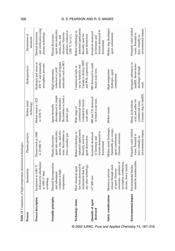
G. S. PEARSON AND R. S. MAGEE
© 2002 IUPAC, Pure and Applied Chemistry 74, 187–316
306Ta
ble
11C
ompa
riso
n of
hig
h-te
mpe
ratu
re d
estr
uctio
n te
chno
logi
es.
Pro
cess
Inci
nera
tion
Plas
ma
pyro
lysi
sM
olte
n m
etal
H
ydro
geno
lysi
sD
estr
uctio
n of
te
chno
logy
arse
nica
ls
Pro
cess
des
crip
tion
Inci
nera
tor
at 1
480
°C
Plas
ma
torc
h at
100
0 M
olte
n m
etal
at 1
425
Hyd
roge
n an
d st
eam
at
The
rmal
des
truc
tion
follo
wed
by
afte
rbur
ner
to 2
0 00
0 °C
.to
165
0 °C
.85
0 °C
and
nom
inal
lyan
d vi
trif
icat
ion
usin
gat
109
0 °C
then
atm
osph
eric
pre
ssur
e.pl
asm
a te
chno
logy
.sc
rubb
ing.
Scie
ntif
ic p
rinc
iple
sT
herm
al d
ecom
posi
tion
Pl
asm
a di
ssoc
iate
sA
gent
ther
mal
ly
Hig
h-te
mpe
ratu
re
Plas
ma
diss
ocia
tes
and
subs
eque
nt
agen
t int
o m
olec
ules
,de
com
pose
d to
sim
ple
redu
ctio
n to
yie
ld
agen
t int
o m
olec
ules
, ox
idat
ion
at h
igh
atom
s, io
ns, a
nd e
lec-
inor
gani
c m
olec
ules
. m
etha
ne a
nd in
orga
nic
atom
s, io
ns, a
nd
tem
pera
ture
s.tr
ons.
Rec
ombi
nes
to
Rec
ombi
nes
to f
orm
a
mol
ecul
es s
uch
as H
Cl.
elec
tron
s. G
aseo
us
form
a p
rodu
ct g
as.
prod
uct g
as.
prod
ucts
oxi
dize
d at
12
00 °
C f
or >
2 s.
Tech
nolo
gy s
tatu
sM
ore
chem
ical
age
nt
Rob
ust t
echn
olog
y in
W
ide
rang
e of
C
omm
erci
al u
nits
in
Rob
ust t
echn
olog
y in
ha
s be
en d
estr
oyed
by
indu
stri
al a
pplic
atio
ns.
com
mer
cial
was
tes
use
in A
ustr
alia
and
indu
stri
al a
pplic
atio
ns.
inci
nera
tion
than
by
Rec
ently
use
d fo
rev
alua
ted
in b
ench
-C
anad
a to
des
troy
DD
TR
ecen
tly u
sed
for
any
othe
r te
chno
logy
.ag
ent d
estr
uctio
n.sc
ale
units
.an
d PC
B, r
espe
ctiv
ely.
agen
t des
truc
tion.
Qua
ntit
y of
age
nt
>17
000
tons
Ars
enic
als
dest
roye
d
HD
and
VX
des
troy
ed
HD
des
troy
ed in
sm
all
Ars
enic
als
dest
roye
d de
stro
yed
in G
erm
any
and
in b
ench
-sca
le te
sts.
benc
h-sc
ale
test
s.in
Ger
man
y an
d le
wis
ite d
estr
oyed
in
lew
isite
des
troy
ed in
Switz
erla
nd.
Switz
erla
nd.
Safe
ty c
onsi
dera
tion
sM
onito
r to
pre
vent
Mol
ten
met
al d
isch
arge
s,
Mol
ten
met
al.
Hig
h-te
mpe
ratu
re
Mol
ten
slag
dis
char
ges,
re
leas
e th
roug
h st
ack
flam
mab
le g
as s
tora
ge,
hydr
ogen
, age
nt
agen
t con
tain
men
t.of
age
nt. G
aseo
usag
ent c
onta
inm
ent.
cont
ainm
ent.
emis
sion
s—pr
oduc
ts o
fG
aseo
us e
mis
sion
s.in
com
plet
e co
mbu
stio
n,di
oxin
s, h
eavy
met
als.
Env
iron
men
tal i
mpa
ctE
nvir
onm
enta
l bur
den
Prim
arily
sol
id v
itrif
ied
M
etal
, hyd
roch
lori
c
Inor
gani
c su
bsta
nces
to
Prim
arily
sol
id v
itrif
ied
shou
ld b
e no
ndet
ecta
ble.
was
te. P
oten
tial t
o ac
id, a
nd s
ulfu
r fo
rla
ndfi
ll. S
team
boi
ler
was
te. P
oten
tial t
o ha
ve v
irtu
ally
no
com
mer
cial
reu
se.
disc
harg
es th
roug
h ha
ve v
irtu
ally
no
envi
ronm
enta
l im
pact
.C
eram
ic s
lag
to la
ndfi
ll.st
ack.
envi
ronm
enta
l im
pact
.

© 2002 IUPAC, Pure and Applied Chemistry 74, 187–316
Critical evaluation of proven chemical weapon destruction technologies 307Ta
ble
12C
ompa
riso
n of
low
-tem
pera
ture
des
truc
tion
tech
nolo
gies
.
Pro
cess
Hyd
roly
sis
of m
usta
rdH
ydro
lysi
s of
mus
tard
R
eact
ion
of m
usta
rd a
ndE
lect
roch
emic
al o
xida
tion
Solv
ated
ele
ctro
n an
d ne
rve
agen
ts u
sing
nerv
e ag
ents
usi
ng
tech
nolo
gyaq
ueou
s N
aOH
amin
es a
nd o
ther
re
agen
ts
Pro
cess
des
crip
tion
Hyd
roly
sis
with
hot
H
ydro
lysi
s w
ith a
queo
us
Hyd
roly
sis
with
Ag(
II)/
Ag(
I)
Red
uctio
n by
sol
utio
nw
ater
.so
dium
hyd
roxi
de.
mon
etha
nola
min
eel
ectr
oche
mic
al c
ell.
of m
etal
lic s
odiu
m in
follo
wed
by
anhy
drou
s liq
uid
bitu
men
izat
ion
of
amm
onia
.re
actio
n pr
oduc
ts (
or
inci
nera
tion)
.
Scie
ntif
ic p
rinc
iple
sR
eact
ion
of m
usta
rd w
ith
Hyd
roly
sis
reac
tion
H
ydro
lysi
s re
actio
n
Ag(
II)
in a
cidi
c m
ediu
mR
educ
tion
of m
usta
rd to
w
ater
to p
rodu
ce
prod
ucts
dep
ende
nt o
npr
oduc
ts d
epen
dent
on
is o
ne o
f th
e m
ost
sodi
um c
hlor
ide
and
ofth
iodi
glyc
ol a
nd
agen
t and
neu
tral
izin
gag
ent a
nd n
eutr
aliz
ing
pow
erfu
l oxi
dizi
ng a
gent
sG
B to
sod
ium
flu
orid
e.hy
droc
hlor
ic a
cid.
reag
ent c
once
ntra
tions
.re
agen
t.kn
own.
VX
unc
erta
in.
Tech
nolo
gy s
tatu
sU
sed
to d
etox
ify
mus
tard
E
xten
sive
ly u
sed
to
Kua
si m
obile
sys
tem
Y
et to
be
oper
ated
on
a Y
et to
be
oper
ated
on
a ag
ent.
deto
xify
mus
tard
and
us
ed in
Rus
sia
to
com
mer
cial
sca
le.
com
mer
cial
sca
le.
GB
age
nt.
dest
roy
H, G
B, G
D
mun
ition
s.
Qua
ntit
y of
age
nt
>15
0 kg
H>
700
tonn
es H
>
300
tonn
es H
, GB
, GD
Pi
lot p
lant
sca
le (
~10
kg
0.64
kg
HD
, 0.5
9 kg
de
stro
yed
>38
00 to
nnes
GB
in K
uasi
sys
tem
with
quan
titie
s) w
ith H
D, G
B,
GB
, 0.4
5 kg
VX
inci
nera
tion
of p
rodu
cts.
VX
.
Safe
ty c
onsi
dera
tion
sSe
mib
atch
pro
cess
with
Sem
ibat
ch p
roce
ss w
ithB
atch
pro
cess
with
low
-H
ighl
y co
rros
ive
orL
iqui
d so
dium
and
no
nfla
mm
able
low
-no
nfla
mm
able
low
-te
mpe
ratu
re (
100
°C)
reac
tive
mat
eria
ls—
liqui
d am
mon
ia a
rete
mpe
ratu
re (
90 °
C)
tem
pera
ture
(90
°C
)aq
ueou
s m
onoe
than
ol-
aque
ous
conc
entr
ated
high
ly r
eact
ive.
aque
ous
stre
ams
at
aque
ous
stre
ams
atam
ine/
RD
-4 s
trea
ms
nitr
ic a
cid—
at 9
0 °C
Sodi
um p
ersu
lpha
teat
mos
pher
ic p
ress
ure.
atm
osph
eric
pre
ssur
e.at
atm
osph
eric
and
atm
osph
eric
an
d hy
drog
en p
erox
ide
pres
sure
.pr
essu
re.
solu
tions
are
rea
ctiv
eB
itum
eniz
atio
n at
oxid
izer
s.18
0–20
0 °C
.
(con
tinu
ed o
n ne
xt p
age)

Tabl
e 12
(Con
tinu
ed).
Pro
cess
Hyd
roly
sis
of m
usta
rdH
ydro
lysi
s of
mus
tard
R
eact
ion
of m
usta
rd a
ndE
lect
roch
emic
al o
xida
tion
Solv
ated
ele
ctro
n an
d ne
rve
agen
ts u
sing
nerv
e ag
ents
usi
ng
tech
nolo
gyaq
ueou
s N
aOH
amin
es a
nd o
ther
re
agen
ts
Env
iron
men
tal i
mpa
ctTe
st p
rior
to r
elea
se.
Test
pri
or to
rel
ease
.A
bilit
y of
bitu
men
ized
Te
st p
rior
to r
elea
se.
Eff
luen
ts n
ot
Was
te s
alts
to la
ndfi
ll.W
aste
sal
ts to
land
fill.
bloc
ks to
with
stan
dA
queo
us w
aste
sal
tssu
ffic
ient
ly
Wat
er r
ecyc
le o
r di
lute
Wat
er r
ecyc
le o
r di
lute
leac
hing
nee
ds to
be
with
low
silv
er
char
acte
rize
d.aq
ueou
s di
scha
rge
toaq
ueou
s di
scha
rge
tode
term
ined
.co
ncen
trat
ions
.tr
eatm
ent p
lant
.tr
eatm
ent p
lant
.
G. S. PEARSON AND R. S. MAGEE
© 2002 IUPAC, Pure and Applied Chemistry 74, 187–316
308

© 2002 IUPAC, Pure and Applied Chemistry 74, 187–316
Critical evaluation of proven chemical weapon destruction technologies 309
XI. TECHNOLOGIES AND CONSTRAINTS: MAKING INFORMED DECISIONS
1. The IUPAC Working Party on Evaluation of Chemical Weapon Destruction Technologies hasexamined and evaluated the technologies for the destruction of chemical weapons that have beendemonstrated on 1 kg or more of agent. The Working Party has recognized that all chemicalagents are highly toxic chemicals, which were made available for use in chemical weapons pro-grams from ongoing work in chemistry. There is, therefore, a sense in which chemical agents aremerely members of a vast array of chemicals of varying toxicity. Consequently, it is logical toconsider the destruction of chemical agents as being no different from the consideration of thedestruction of other chemicals that can be as highly toxic. Chemical agents therefore need notbe regarded as being a special class of materials whose destruction demands unique pre-cautions—they are merely members of the vast family of chemicals, and their destruction,as that of any chemicals, requires the taking of appropriate precautions to safeguard workersafety, public health, and the environment.
2. The Chemical Weapons Convention, which entered into force on 29 April 1997, totally prohibitsthe development, production, transfer, acquisition, stockpiling, retention, and use of chemicalweapons. It obliges all States Parties to destroy any stockpiles of chemical weapons within 10years from the entry into force of the Convention—by 29 April 2007—with the possibility of anextension, should that be necessary, for up to 5 years to 29 April 2012. There is consequently atight time line under the treaty for the destruction of stockpiled chemical weapons and agents.This requires that destruction facilities be designed, constructed, and brought into operation in ashort time frame, while at the same time protecting public health and the environment. This seri-ously constrains opportunities for significant technology development. These stockpiled weaponsand agents are primarily filled with mustard or with nerve agents. Abandoned or old chemicalweapons—sometimes referred to as non-stockpile chemical weapons—also have to be destroyed.As such abandoned chemical weapons are often found during building works and excavations oras a result of farming activities, they will continue to be found for decades in countries wherechemical weapons have previously been used or held. The quantities found from time to time arelikely to be small and variable at widely dispersed locations. Moreover, the nature of theweapon—whether it is a chemical weapon, still contains chemical agents, and what type of chem-ical agent—is unlikely to be known. In practice, therefore, there are two principal categories ofchemical weapons:
a. stockpiled chemical weapons in known quantities with known fillings and which haveto be destroyed by 29 April 2007 with a possible extension to 29 April 2012, and
b. abandoned chemical weapons in unknown types and quantities at unknown locationsthat are found from time to time and which have to be destroyed also by 29 April 2007unless the Executive Council decides to modify the provisions on the time limit.
3. Following the entry into force of the CWC, a total figure has been published by the Organizationfor the Prohibition of Chemical Weapons (OPCW) for the chemical agents declared anddestroyed. The figure as of 30 June 2001 for the total declared is 69 863 agent-tonnes, and thetotal destroyed is 5734 agent-tonnes. The principal contributors to the global stockpile are theUnited States and the Russian Federation; the United States has declared its stockpile as com-prising some 31 495 agent-tons (short tons) [137] which corresponds to 28 570 agent-tonnes,
137. U.S. Department of Defense News Release. U.S. Chemical Weapons Stockpile InformationDeclassified, Reference Number No. 024-96, 22 January 1996. Available athttp://www.defenselink.mil/news/ Jan1996/b12496_bt024-96.htm

G. S. PEARSON AND R. S. MAGEE
© 2002 IUPAC, Pure and Applied Chemistry 74, 187–316
310
whereas the Russian Federation has declared [138] a stockpile of about 40 000 agent-tonnes. AsIndia and one other country, known from non-OPCW information, to be South Korea, have alsodeclared chemical weapons, the combined stockpiles for these two countries can be deduced asbeing about 1500 agent-tonnes. As of July 2001, the United States had destroyed using incinera-tion 20 % [139] of its stockpiled chemical weapons—or some 5700 agent-tonnes. In addition tostockpiled chemical weapons, there are also quantities of old and abandoned chemical weaponsin several countries around the world—notably in Europe primarily from World War I, in Chinafrom World War II as well as in the United States—which also need to be destroyed.
4. The quantity of chemical weapons that have been destroyed during the past 40 years in a numberof countries has been in excess of 20 000 tonnes. Most of this, over 16 000 tonnes, has beendestroyed by incineration, and 4000 tonnes have been destroyed by neutralization. More chemi-cal weapons have been destroyed by incineration than by any other technology.
5. Although incineration is well proven and had been used in the United States at the full-scaledestruction facilities at Johnston Atoll and at Tooele Army Depot, Utah to destroy by October2001 over 6700 tonnes of the U.S. declared stockpile of 28 500 tonnes, and is to be used to destroyover 80 % of the total U.S. stockpile, there has been considerable attention paid particularly in theUnited States to alternative technologies to incineration for the destruction of stockpiled chemi-cal weapons and agents. The reason for the attention given to alternative technologies has arisenfrom a number of constraints that are specific to the United States. First, the United States founditself in a situation where the U.S. Congress passed a law that prohibited the transportation ofchemical weapons from one storage site to another storage site, thus precluding the option of car-rying out all destruction at a single or a few destruction facilities. This situation appears illogicalwhen it is recalled that the stockpiles of chemical weapons were created by transporting agent andmunitions from manufacturing facilities to the stockpile sites and any deployment of theseweapons prior to use would have necessitated transportation of the weapons to the battlefield. Partof the justification for the prohibition of the transportation of the stockpiled chemical weaponsarose from the age, and thus the uncertain state, of the chemical weapons (which are all over 30years old and some are over 55 years old) and the reluctance of individual States to allow trans-port of these munitions across State boundaries. Second, and most importantly, although the U.S.Army had proposed the construction of similar incineration facilities to those at Johnston Atolland Tooele at the other seven storage sites in the continental United States, some groups and indi-viduals have claimed that the incineration technology poses risks to the surrounding populationsand the environment and that these risks could be reduced, it is claimed, by using alternative tech-nologies. The U.S. Congress has accordingly directed the U.S. Army to examine alternative dis-posal technologies.
6. The U.S. consideration of alternative technologies for the destruction of stockpiled chemicalweapons and agents has been tightly constrained by the available resources and the time prior tothe Chemical Weapons Convention deadline for destruction to be completed by 29 April 2007.
138. Government of the Russian Federation, Resolution No. 510 of 5 July 2001, On MakingAmendments and Additions to the Resolution by the Government of the Russian Federation ofMarch 21, 1996 (No. 305) On Approving the Federal Special Program “Chemical WeaponsStockpiles Destruction in the Russian Federation”. Available at http:www.armscontrol.org
139. A. Johnson-Winegar. The U.S. Chemical Demilitarization Program, Statement before the SenateArmed Services Committee, Sub-Committee on Emerging Threats and Capabilities, UnitedStates Senate, 12 July 2001.

© 2002 IUPAC, Pure and Applied Chemistry 74, 187–316
Critical evaluation of proven chemical weapon destruction technologies 311
The first extensive study of alternative technologies was carried out in 1993 when the NationalResearch Council report [140] concluded that “There are many possible destruction processes.”The report went on to point out that “new components would likely require 5 to 12 years forresearch and demonstration.” A further National Research Council report [141] a year later rec-ommended that the disposal program “should continue on schedule with implementation of thebaseline [incineration] system, unless and until alternatives are developed and proven to offersafer, less costly, and more rapidly implementable technologies.” In respect of alternatives, thesame report “determined that four neutralization based systems offer the most promise for agentdestruction” and recommended that “neutralization followed by transport should be examined, asan alternative at the Aberdeen and Newport sites” as these sites only have ton containers of agentand have no filled chemical munitions. The design and construction of neutralization facilities todestroy the bulk agent at the Aberdeen and Newport sites is now underway, with destructionplanned to commence in 2004–2005.
7. Insofar as the remaining five storage sites in the continental United States that all contain assem-bled chemical weapons as well as, in most cases, one-ton containers, incineration continues to bethe planned approach for disposal. However, in late 1996, the U.S. Congress stopped any work onconstruction of incineration facilities at two sites (Lexington, Kentucky and Pueblo, Colorado)until the U.S. Department of Defense had completed an assessment of the chemical demilitariza-tion program for destruction of assembled chemical munitions and of the alternative demilita-rization technologies and processes (other than incineration) which could be used for the destruc-tion of chemical agents. It was also specified that not less than two alternative technologies shouldbe identified and demonstrated. This Assembled Chemical Weapons Assessment (ACWA) pro-gram led to the identification of seven “technology packages”, which were reviewed and evalu-ated by the National Research Council [142]. The National Research Council report made a gen-eral finding that “The chemistries of all four of the primary technologies, (hydrolysis, SILVER II,plasma arc and SET) as proposed, can decompose the chemical agents with destruction efficien-cies of 99.9999 per cent. However, each technology package raises other technical issues whichmust be resolved. One of the crucial issues is the identity and disposition of by-products.” Anothergeneral finding was that “An extraordinary commitment of resources will be necessary to com-plete the destruction of the assembled chemical weapons stockpile in time to meet the currentdeadline using any of the ACWA technology packages. This would demand a concerted nationaleffort. It is unlikely that any of the technology packages could meet this deadline.” In July 1998,the Department of Defense selected three technologies, two relying on hydrolysis as the primarytreatment process and the third on plasma arc technology, for demonstration. A further National
140. National Research Council, Committee on Alternative Chemical Demilitarization Technologies.Alternative Technologies for the Destruction of Chemical Agents and Munitions, NationalAcademy Press (1993).
141. National Research Council, Committee on Review and Evaluation of the Army ChemicalStockpile Disposal Program. Recommendations for the Disposal of Chemical Agents andMunitions, National Academy Press (1994).
142. National Research Council, Committee on Review and Evaluation of Alternative Technologiesfor Demilitarization of Assembled Chemical Weapons. Review and Evaluation of AlternativeTechnologies for Demilitarization of Assembled Chemical Weapons, National Academy Press,Washington, DC (1999).

Research Council report [143] examined the results of demonstration tests carried out on thesethree technologies. A general finding was that “The committee reiterates that none of the unitoperations has been integrated into a complete system. The lack of integration remains a majorconcern as a significant obstacle to full-scale implementation.”
8. Currently, incineration facilities are under construction at Anniston, Alabama; Pine Bluff,Arkansas; and Umatilla, Oregon. These facilities are similar to the facility currently in operationat Tooele, Utah, with the main difference being the addition of a carbon filter on the pollutionabatement system. The technology decision for Pueblo, Colorado is scheduled to be made inSeptember 2001. Four technological approaches are being considered for use at Pueblo: baselineincineration (as at Anniston, Pine Bluff, and Umatilla); modified baseline incineration (with ener-getics removal and off-site disposal, freezing of mustard rounds, and processing of the mustardrounds in a single furnace); and two ACWA-developed technologies: hydrolysis/biotreatment andhydrolysis/supercritical water oxidation. The situation in respect of the U.S. stockpiled chemicalmunitions is summarized in Table 13.
Table 13 Schedule for destruction of U.S. stockpiled chemical munitions (as of October 2001)a.
Site Agent % U.S. Stockpile nature Technology Full-scaleshort tons stockpile destruction
Aberdeen 1625 tons 5.2 % HD containers Neutralization 2005–2006Anniston 2254 tons 7.2 % HD, HT, GB, VX Incineration 2002–
munitionsHD containers
Blue Grass 523 tons 1.7 % H, GB, VX On holdmunitions
Johnston Atoll 2030 tons 6.4 % HD, GB, VX Incineration 1989–2000munitions and Completedcontainers
Newport 1269 tons 4.0 % VX containers Neutralization 2004Pine Bluff 3850 tons 12.2 % HD, HT containers Incineration 2003–
GB, VX munitionsPueblo 2611 tons 8.3 % HD, HT munitions On holdb
Tooele 13 616 tons 43.2 % HD, L, GA, GB, Incineration 1996–VX containers 39.4 % destroyedH, HD, HT, GB, VX munitions
Umatilla 3717 tons 11.8 % HD containers Incineration 2002GB, VX munitions
Total 31 495 100 % 23.5 % destroyedagent-tons
Total 28 572 100 % 23.5 % destroyedagent-tonnes
aThis is based on stockpile information available at http://www.defenselink.mil/news/Jan1996 /b012496_bt024-96.html andinformation on destruction schedules at individual storage sites available at http://www-pmcd.apgea.army.mil/bTechnology decision expected in late 2001.
G. S. PEARSON AND R. S. MAGEE
© 2002 IUPAC, Pure and Applied Chemistry 74, 187–316
312
143. National Research Council, Committee on Review and Evaluation of Alternative Technologiesfor Demilitarization of Assembled Chemical Weapons. Review and Evaluation of AlternativeTechnologies for Demilitarization of Assembled Chemical Weapons A Supplemental Review,National Academy Press, Washington, DC (2000).

It is evident that over 23.5 % of the U.S. stockpile has already been destroyed. Overall, 80.8 % isto be destroyed by incineration, 9 % is planned to be destroyed by neutralization, and 10 %is currently on hold.
9. This Working Party is acutely aware that much of the information presented in this report is basedon U.S. experience. However, this is hardly surprising as the United States had along with theRussian Federation by far the largest stockpiles of chemical weapons and agents anywhere in theworld. The United States has made much progress in destroying its stockpile of chemicalweapons and agents and has also done more work than any other country to examine alternativetechnologies for the destruction of chemical weapons and agents. This report therefore drawsheavily on the U.S. experience. However, the national decisions to be taken by countries facedwith the destruction of chemical weapons and agents need to be made in the light of the par-ticular national conditions and standards—and thus may well result in a decision to use dif-ferent approaches from those adopted by the United States. National decisions in other countrieswill need to consider the size and nature of their stockpiled chemical weapons in determining bothwhere and how to destroy them in accordance with the requirements of and the deadline estab-lished in the Chemical Weapons Convention. The aim of this report is to provide informationto enable countries to make informed decisions that are appropriate for that country.
© 2002 IUPAC, Pure and Applied Chemistry 74, 187–316
Critical evaluation of proven chemical weapon destruction technologies 313

GLOSSARY OF ACRONYMS
AC hydrogen cyanide (a blood agent)ACAMS automated continuous air monitoring systemACW abandoned chemical weaponsACWA assembled chemical weapons assessmentAg silverAltTech NRC Panel on Review and Evaluation of Alternative Chemical Disposal
TechnologiesAOP advanced oxidation processBATNEEC best available techniques not entailing excessive costsBBC α-bromobenzylcyanide; 1-bromo-1-tolunitrile; also known as CABPEO best practical environmental optionCA 1-bromo-1-tolunitrile; α-bromobenzylcyanide; also known as BBCCAIS chemical agent identification setsCAMDS Chemical Agent Munitions Disposal System at the Tooele Army Depot, Utah, USACEP catalytic extraction processing, a molten metal processCG phosgene (a choking gas)CK cyanogen chloride (a choking gas)CN 1-chloroacetophenone (a tear gas agent)CO carbon monoxideCO2 carbon dioxideCW chemical weaponCWC Chemical Weapons ConventionDA diphenylchloroarsine (Clark I) (an irritating and vomiting agent)DAP Destruction Advisory Panel established by UNSCOMDAAMS depot area air monitoring systemDC diphenylcyanoarsine (Clark II) (an irritating and vomiting agent)DCD Deseret Chemical Depot, USADCMDH 1,3-dichloro-5,5-dimethylhydantoinDDT dichloro diphenyl trichloroethaneDERA Defence Evaluation and Research Agency, UKDFS deactivation furnaceDM Adamsite (a tear gas agent)DNT dinitrotolueneDRE destruction removal efficiencyDRES Defence Research Establishment Suffield, CanadaEMPA ethyl methyl-phosphonic acidEOD explosive ordnance disposalEPA U.S. Environmental Protection AgencyGA tabun (a nerve agent)GAC granular activated charcoalGB sarin (a nerve agent)GD soman (a nerve agent)H mustard (a blister agent)HCl hydrogen chlorideHD distilled mustard (a blister agent)HE high explosiveHEPA high-efficiency particulate airHN nitrogen mustard
G. S. PEARSON AND R. S. MAGEE
© 2002 IUPAC, Pure and Applied Chemistry 74, 187–316
314

HN-1 bis(2-chloroethyl)ethylamine, a nitrogen mustardHN-2 bis(2-chloroethyl)methylamine, a nitrogen mustardHN-3 bis(2-chloroethyl)amine, a nitrogen mustardH2O waterH2S hydrogen sulfideHT a low freezing-point blister agent, also known as Runcold, produced by reacting
thiodiglycol and hydrogen chloride so as to yield a product containing about 60 % mustard and 40 % bis-(2-chloroethylthioethyl) ether
I incinerationISO International Standards OrganizationITEQ international toxic equivalencyIUPAC International Union of Pure and Applied ChemistryJACADS Johnston Atoll Chemical Agent Disposal SystemJI Johnston IslandL lewisite (a blister agent)LIC liquid incineratorMACT maximum achievable control technologyMEA monoethanolamineMECC mobile explosion containment chamberMILVANS standard transportation vansMMD munitions management deviceMPA methyl phosphonic acidMPF metal parts furnaceN neutralizationNAA neutron activation analysisNO nitric oxideNaOH sodium hydroxide (caustic soda)NBC nuclear biological chemicalNRC National Research Council of the U.S. National Academy of SciencesOCW old chemical weaponsOPCW Organization for the Prohibition of Chemical WeaponsOSHA Occupational Safety and Health Act, a U.S. law passed in 1970OVT operational verification testPACOM U.S. Pacific CommandPAR projectile agent removal systemPCB polychlorinated biphenylpH hydrogen ion concentrationPICs products of incomplete combustionppb parts per billionPS chloropicrin (a tear gas)PWC plasma waste converterRCRA Resource Conservation and Recovery ActRMA Rocky Mountain Arsenal, USARRS rapid response systemSBR sequencing batch reactorSCWO supercritical water oxidationSET solvated electron technology S/S stabilization and solidificationTNT trinitrotolueneTOCDF Tooele Chemical Agent Disposal Facility at Tooele Army Depot, Utah, USA
© 2002 IUPAC, Pure and Applied Chemistry 74, 187–316
Critical evaluation of proven chemical weapon destruction technologies 315

TSCA Toxic Substances Control ActTSDF treatment, storage, or disposal facility UK United KingdomUNSCOM United Nations Special Commission on IraqUNSCR United Nations Security Council ResolutionU.S. United StatesUSA United States of AmericaUSARPAC U.S. Army PacificUV ultravioletVOCs volatile organic compoundsVR a nerve agent, Russian VX, O-isobutyl S-[2-diethyamino ethyl] methyl phosphono-
thiolateVX a nerve agent, O-ethyl S-2-diisopropylaminoethyl methyl phosphonothiolateWWI World War IWWII World War II
G. S. PEARSON AND R. S. MAGEE
© 2002 IUPAC, Pure and Applied Chemistry 74, 187–316
316