GSM Based Embedded Medical Critical Care Signal Monitoring System

Critical Care MonitoringClinical Reference and Troubleshooting Guide
2024578-001 Revision A

T-2 Clinical Reference and Troubleshooting Revision A2007725-001 31 January 2005
������Due to continuing product innovation, information in this manual is subject to change without notice.
Listed below are GE Medical Systems Information Technologies trademarks used in this document. All other trademarks contained herein are the property of their respective owners.
CD TELEMETRY, CRG PLUS, MUSE, QS, RAC, RAMS, SAM, SOLAR, ST GUARD, TRAM, TRAM-NET, TRAM-RAC, TRIM KNOB, and UNITY NETWORK are trademarks of GE Medical Systems Information Technologies registered in the United States Patent and Trademark Office.
12SL, ApexPro, CD TELEMETRY®-LAN, CENTRALSCOPE, EK-Pro, IMPACT.wf, MENTOR, Octanet, PRN 50, PRN 50-M, and UNITY are trademarks of GE Medical Systems Information Technologies.
© 2005 General Electric Company. All rights reserved.

Revision A Clinical Reference and Troubleshooting i2007725-001
Contents
1 Introduction . . . . . . . . . . . . . . . . . . . . . . . . . . . . . . . . . . . . 1-1About This Manual . . . . . . . . . . . . . . . . . . . . . . . . . . . . . . . . . . . . . . . . . . . . . . . . . . . 1-3
Manual Purpose . . . . . . . . . . . . . . . . . . . . . . . . . . . . . . . . . . . . . . . . . . . . . . . . . . . 1-3Intended Audience . . . . . . . . . . . . . . . . . . . . . . . . . . . . . . . . . . . . . . . . . . . . . . . . . 1-3Revision History . . . . . . . . . . . . . . . . . . . . . . . . . . . . . . . . . . . . . . . . . . . . . . . . . . . 1-3Ordering Manuals . . . . . . . . . . . . . . . . . . . . . . . . . . . . . . . . . . . . . . . . . . . . . . . . . 1-3
Manual Conventions . . . . . . . . . . . . . . . . . . . . . . . . . . . . . . . . . . . . . . . . . . . . . . . . . 1-4Text Conventions . . . . . . . . . . . . . . . . . . . . . . . . . . . . . . . . . . . . . . . . . . . . . . . . . . 1-4Illustrations and Names . . . . . . . . . . . . . . . . . . . . . . . . . . . . . . . . . . . . . . . . . . . . . 1-4
Safety Information . . . . . . . . . . . . . . . . . . . . . . . . . . . . . . . . . . . . . . . . . . . . . . . . . . . 1-5Complete Safety Information . . . . . . . . . . . . . . . . . . . . . . . . . . . . . . . . . . . . . . . . . 1-5Terminology . . . . . . . . . . . . . . . . . . . . . . . . . . . . . . . . . . . . . . . . . . . . . . . . . . . . . . 1-5Dangers . . . . . . . . . . . . . . . . . . . . . . . . . . . . . . . . . . . . . . . . . . . . . . . . . . . . . . . . . 1-5Warnings . . . . . . . . . . . . . . . . . . . . . . . . . . . . . . . . . . . . . . . . . . . . . . . . . . . . . . . . 1-6Cautions . . . . . . . . . . . . . . . . . . . . . . . . . . . . . . . . . . . . . . . . . . . . . . . . . . . . . . . . . 1-8
2 Calculation Programs . . . . . . . . . . . . . . . . . . . . . . . . . . . . 2-1Introduction . . . . . . . . . . . . . . . . . . . . . . . . . . . . . . . . . . . . . . . . . . . . . . . . . . . . . . . . 2-3
Cardiac Calculations . . . . . . . . . . . . . . . . . . . . . . . . . . . . . . . . . . . . . . . . . . . . . . . . . 2-4Monitored Parameters . . . . . . . . . . . . . . . . . . . . . . . . . . . . . . . . . . . . . . . . . . . . . . 2-4Calculated Parameters . . . . . . . . . . . . . . . . . . . . . . . . . . . . . . . . . . . . . . . . . . . . . 2-5
Pulmonary Calculations . . . . . . . . . . . . . . . . . . . . . . . . . . . . . . . . . . . . . . . . . . . . . . 2-6Monitored/Measured Parameters . . . . . . . . . . . . . . . . . . . . . . . . . . . . . . . . . . . . . 2-6Derived Pulmonary Calculations . . . . . . . . . . . . . . . . . . . . . . . . . . . . . . . . . . . . . . 2-7Estimated Pulmonary Calculations . . . . . . . . . . . . . . . . . . . . . . . . . . . . . . . . . . . . 2-9
Dose Calculations . . . . . . . . . . . . . . . . . . . . . . . . . . . . . . . . . . . . . . . . . . . . . . . . . . 2-10
3 ECG . . . . . . . . . . . . . . . . . . . . . . . . . . . . . . . . . . . . . . . . . . 3-1Introduction . . . . . . . . . . . . . . . . . . . . . . . . . . . . . . . . . . . . . . . . . . . . . . . . . . . . . . . . 3-3
Skin Preparation . . . . . . . . . . . . . . . . . . . . . . . . . . . . . . . . . . . . . . . . . . . . . . . . . . . . 3-4
Electrode Placement . . . . . . . . . . . . . . . . . . . . . . . . . . . . . . . . . . . . . . . . . . . . . . . . . 3-5

ii Clinical Reference and Troubleshooting Revision A2007725-001
3-Leadwire Electrode Placement . . . . . . . . . . . . . . . . . . . . . . . . . . . . . . . . . . . . . . 3-65-Leadwire Electrode Placement . . . . . . . . . . . . . . . . . . . . . . . . . . . . . . . . . . . . . . 3-86-Leadwire Electrode Configuration . . . . . . . . . . . . . . . . . . . . . . . . . . . . . . . . . . . . 3-910-Leadwire Electrode Configuration for 12SL Monitoring . . . . . . . . . . . . . . . . . 3-10Electrode Placement for Neonates . . . . . . . . . . . . . . . . . . . . . . . . . . . . . . . . . . . 3-12Electrode Placement for Pacemaker Patients . . . . . . . . . . . . . . . . . . . . . . . . . . . 3-13Maintaining Quality ECG Signal . . . . . . . . . . . . . . . . . . . . . . . . . . . . . . . . . . . . . . 3-14Electrosurgical Unit (ESU) Cable . . . . . . . . . . . . . . . . . . . . . . . . . . . . . . . . . . . . . 3-14
Pacemaker Detection . . . . . . . . . . . . . . . . . . . . . . . . . . . . . . . . . . . . . . . . . . . . . . . 3-15Safety Considerations . . . . . . . . . . . . . . . . . . . . . . . . . . . . . . . . . . . . . . . . . . . . . 3-15Monitoring Pacemaker Patients . . . . . . . . . . . . . . . . . . . . . . . . . . . . . . . . . . . . . . 3-17
Arrhythmia Analysis . . . . . . . . . . . . . . . . . . . . . . . . . . . . . . . . . . . . . . . . . . . . . . . . 3-19Lethal Arrhythmia Analysis . . . . . . . . . . . . . . . . . . . . . . . . . . . . . . . . . . . . . . . . . 3-19Full Arrhythmia Analysis . . . . . . . . . . . . . . . . . . . . . . . . . . . . . . . . . . . . . . . . . . . 3-20Arrhythmia Conditions . . . . . . . . . . . . . . . . . . . . . . . . . . . . . . . . . . . . . . . . . . . . . 3-20
Troubleshooting . . . . . . . . . . . . . . . . . . . . . . . . . . . . . . . . . . . . . . . . . . . . . . . . . . . 3-24Pacemaker Troubleshooting . . . . . . . . . . . . . . . . . . . . . . . . . . . . . . . . . . . . . . . . 3-26
4 Invasive Blood Pressures . . . . . . . . . . . . . . . . . . . . . . . . 4-1Introduction . . . . . . . . . . . . . . . . . . . . . . . . . . . . . . . . . . . . . . . . . . . . . . . . . . . . . . . . 4-3
Assigned Pressure Names . . . . . . . . . . . . . . . . . . . . . . . . . . . . . . . . . . . . . . . . . . . . 4-4
IABP . . . . . . . . . . . . . . . . . . . . . . . . . . . . . . . . . . . . . . . . . . . . . . . . . . . . . . . . . . . . . . 4-6Triggering . . . . . . . . . . . . . . . . . . . . . . . . . . . . . . . . . . . . . . . . . . . . . . . . . . . . . . . . 4-6
Smart BP . . . . . . . . . . . . . . . . . . . . . . . . . . . . . . . . . . . . . . . . . . . . . . . . . . . . . . . . . . 4-10
Disconnect Alarm . . . . . . . . . . . . . . . . . . . . . . . . . . . . . . . . . . . . . . . . . . . . . . . . . . 4-11
Troubleshooting . . . . . . . . . . . . . . . . . . . . . . . . . . . . . . . . . . . . . . . . . . . . . . . . . . . 4-12Wedge Troubleshooting . . . . . . . . . . . . . . . . . . . . . . . . . . . . . . . . . . . . . . . . . . . . 4-13
5 Noninvasive Blood Pressure . . . . . . . . . . . . . . . . . . . . . . 5-1Introduction . . . . . . . . . . . . . . . . . . . . . . . . . . . . . . . . . . . . . . . . . . . . . . . . . . . . . . . . 5-3
Safety . . . . . . . . . . . . . . . . . . . . . . . . . . . . . . . . . . . . . . . . . . . . . . . . . . . . . . . . . . . . . 5-4Warnings . . . . . . . . . . . . . . . . . . . . . . . . . . . . . . . . . . . . . . . . . . . . . . . . . . . . . . . . 5-4Cautions . . . . . . . . . . . . . . . . . . . . . . . . . . . . . . . . . . . . . . . . . . . . . . . . . . . . . . . . . 5-4Notes . . . . . . . . . . . . . . . . . . . . . . . . . . . . . . . . . . . . . . . . . . . . . . . . . . . . . . . . . . . 5-5
Patient Preparation . . . . . . . . . . . . . . . . . . . . . . . . . . . . . . . . . . . . . . . . . . . . . . . . . . 5-6

Revision A Clinical Reference and Troubleshooting iii2007725-001
NBP Monitoring Features . . . . . . . . . . . . . . . . . . . . . . . . . . . . . . . . . . . . . . . . . . . . . 5-8Mean Arterial Pressure . . . . . . . . . . . . . . . . . . . . . . . . . . . . . . . . . . . . . . . . . . . . . 5-8Systolic Search . . . . . . . . . . . . . . . . . . . . . . . . . . . . . . . . . . . . . . . . . . . . . . . . . . . 5-8NBP Auto Timing . . . . . . . . . . . . . . . . . . . . . . . . . . . . . . . . . . . . . . . . . . . . . . . . . . 5-8
Troubleshooting . . . . . . . . . . . . . . . . . . . . . . . . . . . . . . . . . . . . . . . . . . . . . . . . . . . . 5-11
6 SpO2 . . . . . . . . . . . . . . . . . . . . . . . . . . . . . . . . . . . . . . . . . . . . . . . . . . . . . . 6-1Introduction . . . . . . . . . . . . . . . . . . . . . . . . . . . . . . . . . . . . . . . . . . . . . . . . . . . . . . . . 6-3
SpO2 Sensor Compatibility . . . . . . . . . . . . . . . . . . . . . . . . . . . . . . . . . . . . . . . . . . 6-3
Safety . . . . . . . . . . . . . . . . . . . . . . . . . . . . . . . . . . . . . . . . . . . . . . . . . . . . . . . . . . . . . 6-5Warnings . . . . . . . . . . . . . . . . . . . . . . . . . . . . . . . . . . . . . . . . . . . . . . . . . . . . . . . . 6-5
Neonates and Infants . . . . . . . . . . . . . . . . . . . . . . . . . . . . . . . . . . . . . . . . . . . . . . . . . 6-6
Patient Preparation . . . . . . . . . . . . . . . . . . . . . . . . . . . . . . . . . . . . . . . . . . . . . . . . . . 6-7
Signal and Data Validity . . . . . . . . . . . . . . . . . . . . . . . . . . . . . . . . . . . . . . . . . . . . . . 6-8Signal Strength Indicator . . . . . . . . . . . . . . . . . . . . . . . . . . . . . . . . . . . . . . . . . . . . 6-8Quality of SpO2 Waveform . . . . . . . . . . . . . . . . . . . . . . . . . . . . . . . . . . . . . . . . . . . 6-8Stability of SpO2 Waveforms . . . . . . . . . . . . . . . . . . . . . . . . . . . . . . . . . . . . . . . . . 6-9
Masimo SET Technology and Sensors . . . . . . . . . . . . . . . . . . . . . . . . . . . . . . . . . 6-10No Implied License . . . . . . . . . . . . . . . . . . . . . . . . . . . . . . . . . . . . . . . . . . . . . . . 6-10Sensors . . . . . . . . . . . . . . . . . . . . . . . . . . . . . . . . . . . . . . . . . . . . . . . . . . . . . . . . 6-10
Nellcor Sat-Seconds Alarm Management . . . . . . . . . . . . . . . . . . . . . . . . . . . . . . . 6-11
Troubleshooting . . . . . . . . . . . . . . . . . . . . . . . . . . . . . . . . . . . . . . . . . . . . . . . . . . . . 6-15
7 Cardiac Output . . . . . . . . . . . . . . . . . . . . . . . . . . . . . . . . . 7-1Introduction . . . . . . . . . . . . . . . . . . . . . . . . . . . . . . . . . . . . . . . . . . . . . . . . . . . . . . . . 7-3
Cardiac Output Washout Curve . . . . . . . . . . . . . . . . . . . . . . . . . . . . . . . . . . . . . . . 7-3
Bath Probe Setup . . . . . . . . . . . . . . . . . . . . . . . . . . . . . . . . . . . . . . . . . . . . . . . . . . . . 7-4
In-Line Setup . . . . . . . . . . . . . . . . . . . . . . . . . . . . . . . . . . . . . . . . . . . . . . . . . . . . . . . 7-5
Cardiac Calculations . . . . . . . . . . . . . . . . . . . . . . . . . . . . . . . . . . . . . . . . . . . . . . . . . 7-6
Troubleshooting . . . . . . . . . . . . . . . . . . . . . . . . . . . . . . . . . . . . . . . . . . . . . . . . . . . . . 7-7

iv Clinical Reference and Troubleshooting Revision A2007725-001
8 Respiration . . . . . . . . . . . . . . . . . . . . . . . . . . . . . . . . . . . . 8-1General Information . . . . . . . . . . . . . . . . . . . . . . . . . . . . . . . . . . . . . . . . . . . . . . . . . . 8-3
Monitoring Respiration on Pacemaker Patients . . . . . . . . . . . . . . . . . . . . . . . . . . . 8-5
Troubleshooting . . . . . . . . . . . . . . . . . . . . . . . . . . . . . . . . . . . . . . . . . . . . . . . . . . . . 8-6Respiratory Waveform . . . . . . . . . . . . . . . . . . . . . . . . . . . . . . . . . . . . . . . . . . . . . . 8-6
9 Respiratory Mechanics . . . . . . . . . . . . . . . . . . . . . . . . . . . 9-1Introduction . . . . . . . . . . . . . . . . . . . . . . . . . . . . . . . . . . . . . . . . . . . . . . . . . . . . . . . . 9-3
Respiratory Mechanics Parameters . . . . . . . . . . . . . . . . . . . . . . . . . . . . . . . . . . . . 9-3
Patient Connection . . . . . . . . . . . . . . . . . . . . . . . . . . . . . . . . . . . . . . . . . . . . . . . . . . 9-5
RM Waveforms . . . . . . . . . . . . . . . . . . . . . . . . . . . . . . . . . . . . . . . . . . . . . . . . . . . . . . 9-8Sample RM Waveforms . . . . . . . . . . . . . . . . . . . . . . . . . . . . . . . . . . . . . . . . . . . . . 9-8
10 SvO2 . . . . . . . . . . . . . . . . . . . . . . . . . . . . . . . . . . . . . . . . . . . . . . . . . . . . 10-1Introduction . . . . . . . . . . . . . . . . . . . . . . . . . . . . . . . . . . . . . . . . . . . . . . . . . . . . . . . 10-3
Signal Strength Indicator . . . . . . . . . . . . . . . . . . . . . . . . . . . . . . . . . . . . . . . . . . . . 10-5
Troubleshooting . . . . . . . . . . . . . . . . . . . . . . . . . . . . . . . . . . . . . . . . . . . . . . . . . . . 10-6
11 End-Tidal CO2 . . . . . . . . . . . . . . . . . . . . . . . . . . . . . . . . . . . . . . . . . . 11-1Introduction . . . . . . . . . . . . . . . . . . . . . . . . . . . . . . . . . . . . . . . . . . . . . . . . . . . . . . . 11-3
Safety . . . . . . . . . . . . . . . . . . . . . . . . . . . . . . . . . . . . . . . . . . . . . . . . . . . . . . . . . . . . 11-4Cautions . . . . . . . . . . . . . . . . . . . . . . . . . . . . . . . . . . . . . . . . . . . . . . . . . . . . . . . . 11-4
Setup . . . . . . . . . . . . . . . . . . . . . . . . . . . . . . . . . . . . . . . . . . . . . . . . . . . . . . . . . . . . . 11-6Capnostat Mainstream Setup . . . . . . . . . . . . . . . . . . . . . . . . . . . . . . . . . . . . . . . 11-6Capnostat Sidestream Setup (Dual CO2 Module) . . . . . . . . . . . . . . . . . . . . . . . . 11-7Sidestream CO2 Module Setup . . . . . . . . . . . . . . . . . . . . . . . . . . . . . . . . . . . . . 11-13CapnoFlex LF Sidestream CO2 Module Setup . . . . . . . . . . . . . . . . . . . . . . . . . 11-14
Troubleshooting . . . . . . . . . . . . . . . . . . . . . . . . . . . . . . . . . . . . . . . . . . . . . . . . . . 11-15Capnostat Sensor Check . . . . . . . . . . . . . . . . . . . . . . . . . . . . . . . . . . . . . . . . . . 11-15

Revision A Clinical Reference and Troubleshooting v2007725-001
12 Anesthetic Agent Analysis . . . . . . . . . . . . . . . . . . . . . . . 12-1Introduction . . . . . . . . . . . . . . . . . . . . . . . . . . . . . . . . . . . . . . . . . . . . . . . . . . . . . . . 12-3
Two Models . . . . . . . . . . . . . . . . . . . . . . . . . . . . . . . . . . . . . . . . . . . . . . . . . . . . . 12-3
Safety . . . . . . . . . . . . . . . . . . . . . . . . . . . . . . . . . . . . . . . . . . . . . . . . . . . . . . . . . . . . 12-4Cautions . . . . . . . . . . . . . . . . . . . . . . . . . . . . . . . . . . . . . . . . . . . . . . . . . . . . . . . . 12-4Notes . . . . . . . . . . . . . . . . . . . . . . . . . . . . . . . . . . . . . . . . . . . . . . . . . . . . . . . . . . 12-5
Connections . . . . . . . . . . . . . . . . . . . . . . . . . . . . . . . . . . . . . . . . . . . . . . . . . . . . . . . 12-6Gas Exhaust . . . . . . . . . . . . . . . . . . . . . . . . . . . . . . . . . . . . . . . . . . . . . . . . . . . . 12-7
Room Air Calibration . . . . . . . . . . . . . . . . . . . . . . . . . . . . . . . . . . . . . . . . . . . . . . . . 12-8
13 Transcutaneous pO2/pCO2 . . . . . . . . . . . . . . . . . . . . . . . . . . . . . 13-1Introduction . . . . . . . . . . . . . . . . . . . . . . . . . . . . . . . . . . . . . . . . . . . . . . . . . . . . . . . 13-3
Safety . . . . . . . . . . . . . . . . . . . . . . . . . . . . . . . . . . . . . . . . . . . . . . . . . . . . . . . . . . . . 13-4Warnings . . . . . . . . . . . . . . . . . . . . . . . . . . . . . . . . . . . . . . . . . . . . . . . . . . . . . . . 13-4Cautions . . . . . . . . . . . . . . . . . . . . . . . . . . . . . . . . . . . . . . . . . . . . . . . . . . . . . . . . 13-4
Measurement Requirements . . . . . . . . . . . . . . . . . . . . . . . . . . . . . . . . . . . . . . . . . . 13-5Recommended Sites . . . . . . . . . . . . . . . . . . . . . . . . . . . . . . . . . . . . . . . . . . . . . . 13-5Recommended Temperatures . . . . . . . . . . . . . . . . . . . . . . . . . . . . . . . . . . . . . . . 13-6
Applying a Sensor Membrane . . . . . . . . . . . . . . . . . . . . . . . . . . . . . . . . . . . . . . . . 13-7Removing the O-Rings . . . . . . . . . . . . . . . . . . . . . . . . . . . . . . . . . . . . . . . . . . . . . 13-7Cleaning the Sensor Surface . . . . . . . . . . . . . . . . . . . . . . . . . . . . . . . . . . . . . . . . 13-8Applying the Electrolyte Solution . . . . . . . . . . . . . . . . . . . . . . . . . . . . . . . . . . . . . 13-9Applying the New Membrane . . . . . . . . . . . . . . . . . . . . . . . . . . . . . . . . . . . . . . . 13-10
Applying the Sensor . . . . . . . . . . . . . . . . . . . . . . . . . . . . . . . . . . . . . . . . . . . . . . . 13-11Applying the Fixation Ring . . . . . . . . . . . . . . . . . . . . . . . . . . . . . . . . . . . . . . . . . 13-12Adding the Contact Fluid . . . . . . . . . . . . . . . . . . . . . . . . . . . . . . . . . . . . . . . . . . 13-12Inserting the Sensor . . . . . . . . . . . . . . . . . . . . . . . . . . . . . . . . . . . . . . . . . . . . . . 13-13Waiting for a Stabilized Reading . . . . . . . . . . . . . . . . . . . . . . . . . . . . . . . . . . . . 13-13
Barometric Pressure . . . . . . . . . . . . . . . . . . . . . . . . . . . . . . . . . . . . . . . . . . . . . . . 13-14O2 Calibration Values . . . . . . . . . . . . . . . . . . . . . . . . . . . . . . . . . . . . . . . . . . . . 13-14CO2 Calibration Values . . . . . . . . . . . . . . . . . . . . . . . . . . . . . . . . . . . . . . . . . . . 13-15
Correction for the Effects of Heat Applied to the Skin . . . . . . . . . . . . . . . . . . . . 13-16
Sensor Troubleshooting . . . . . . . . . . . . . . . . . . . . . . . . . . . . . . . . . . . . . . . . . . . . 13-17Reduction in O2 and CO2 Sensitivity . . . . . . . . . . . . . . . . . . . . . . . . . . . . . . . . . 13-17

vi Clinical Reference and Troubleshooting Revision A2007725-001
14 ICG . . . . . . . . . . . . . . . . . . . . . . . . . . . . . . . . . . . . . . . . . . 14-1Introduction . . . . . . . . . . . . . . . . . . . . . . . . . . . . . . . . . . . . . . . . . . . . . . . . . . . . . . . 14-3
Safety . . . . . . . . . . . . . . . . . . . . . . . . . . . . . . . . . . . . . . . . . . . . . . . . . . . . . . . . . . . . 14-4Warnings . . . . . . . . . . . . . . . . . . . . . . . . . . . . . . . . . . . . . . . . . . . . . . . . . . . . . . . 14-4Cautions . . . . . . . . . . . . . . . . . . . . . . . . . . . . . . . . . . . . . . . . . . . . . . . . . . . . . . . . 14-4Notes . . . . . . . . . . . . . . . . . . . . . . . . . . . . . . . . . . . . . . . . . . . . . . . . . . . . . . . . . . 14-5Monitoring ICG on Pacemaker Patients . . . . . . . . . . . . . . . . . . . . . . . . . . . . . . . . 14-5
ICG Parameters . . . . . . . . . . . . . . . . . . . . . . . . . . . . . . . . . . . . . . . . . . . . . . . . . . . . 14-6
ICG Formulas . . . . . . . . . . . . . . . . . . . . . . . . . . . . . . . . . . . . . . . . . . . . . . . . . . . . . . 14-7Definitions of Terms . . . . . . . . . . . . . . . . . . . . . . . . . . . . . . . . . . . . . . . . . . . . . . . 14-9
Patient Preparation . . . . . . . . . . . . . . . . . . . . . . . . . . . . . . . . . . . . . . . . . . . . . . . . 14-10Skin Preparation . . . . . . . . . . . . . . . . . . . . . . . . . . . . . . . . . . . . . . . . . . . . . . . . 14-10Sensor Placement . . . . . . . . . . . . . . . . . . . . . . . . . . . . . . . . . . . . . . . . . . . . . . . 14-11Connecting the ICG Cable to the Patient . . . . . . . . . . . . . . . . . . . . . . . . . . . . . . 14-12
ICG Reference Literature . . . . . . . . . . . . . . . . . . . . . . . . . . . . . . . . . . . . . . . . . . . 14-13ICG Parameter Normal Range . . . . . . . . . . . . . . . . . . . . . . . . . . . . . . . . . . . . . . 14-13ICG Technology . . . . . . . . . . . . . . . . . . . . . . . . . . . . . . . . . . . . . . . . . . . . . . . . . 14-13
15 EEG Monitoring . . . . . . . . . . . . . . . . . . . . . . . . . . . . . . . . 15-1Introduction . . . . . . . . . . . . . . . . . . . . . . . . . . . . . . . . . . . . . . . . . . . . . . . . . . . . . . . 15-3
Definitions of Terms . . . . . . . . . . . . . . . . . . . . . . . . . . . . . . . . . . . . . . . . . . . . . . . 15-3
EEG Electrodes . . . . . . . . . . . . . . . . . . . . . . . . . . . . . . . . . . . . . . . . . . . . . . . . . . . . 15-5
EEG Electrode Placement . . . . . . . . . . . . . . . . . . . . . . . . . . . . . . . . . . . . . . . . . . . . 15-6International 10-20 Electrode Placement System . . . . . . . . . . . . . . . . . . . . . . . . 15-6Regional Lead Placements . . . . . . . . . . . . . . . . . . . . . . . . . . . . . . . . . . . . . . . . . 15-8Generic “X” Lead Placement . . . . . . . . . . . . . . . . . . . . . . . . . . . . . . . . . . . . . . . . 15-9Commonly Used Electrode Montages . . . . . . . . . . . . . . . . . . . . . . . . . . . . . . . . . 15-9Skin Preparation . . . . . . . . . . . . . . . . . . . . . . . . . . . . . . . . . . . . . . . . . . . . . . . . 15-11Applying Electrodes . . . . . . . . . . . . . . . . . . . . . . . . . . . . . . . . . . . . . . . . . . . . . . 15-12Connecting the Electrodes to the EEG DSC . . . . . . . . . . . . . . . . . . . . . . . . . . . 15-13
EEG Reference Literature . . . . . . . . . . . . . . . . . . . . . . . . . . . . . . . . . . . . . . . . . . . 15-14
16 BIS Monitoring . . . . . . . . . . . . . . . . . . . . . . . . . . . . . . . . . 16-1Introduction . . . . . . . . . . . . . . . . . . . . . . . . . . . . . . . . . . . . . . . . . . . . . . . . . . . . . . . 16-3
Considerations for Using BIS . . . . . . . . . . . . . . . . . . . . . . . . . . . . . . . . . . . . . . . . 16-3

Revision A Clinical Reference and Troubleshooting vii2007725-001
Safety . . . . . . . . . . . . . . . . . . . . . . . . . . . . . . . . . . . . . . . . . . . . . . . . . . . . . . . . . . . . 16-4Warning . . . . . . . . . . . . . . . . . . . . . . . . . . . . . . . . . . . . . . . . . . . . . . . . . . . . . . . . 16-4Cautions . . . . . . . . . . . . . . . . . . . . . . . . . . . . . . . . . . . . . . . . . . . . . . . . . . . . . . . . 16-4
BIS Sensor Placement . . . . . . . . . . . . . . . . . . . . . . . . . . . . . . . . . . . . . . . . . . . . . . . 16-5Three-Electrode Sensor Placement . . . . . . . . . . . . . . . . . . . . . . . . . . . . . . . . . . . 16-5Four-Electrode Sensor Placement . . . . . . . . . . . . . . . . . . . . . . . . . . . . . . . . . . . . 16-6
BIS Range Guidelines . . . . . . . . . . . . . . . . . . . . . . . . . . . . . . . . . . . . . . . . . . . . . . . 16-7
BIS Spectral Displays . . . . . . . . . . . . . . . . . . . . . . . . . . . . . . . . . . . . . . . . . . . . . . . 16-8
BIS Reference Literature . . . . . . . . . . . . . . . . . . . . . . . . . . . . . . . . . . . . . . . . . . . . . 16-9

viii Clinical Reference and Troubleshooting Revision A2007725-001
For your notes

Revision A Clinical Reference and Troubleshooting 1-12007725-001
1 Introduction

1-2 Clinical Reference and Troubleshooting Revision A2007725-001
For your notes

Revision A Clinical Reference and Troubleshooting 1-32007725-001
Introduction: About This Manual
About This Manual
Manual Purpose
This document is intended to serve as a guide to clinical professionals in a hospital setting. It provides patient application instructions for GE Medical Systems Information Technologies patient monitors.
This manual must be used in conjunction with the operator’s manual specific to your GE Medical Systems Information Technologies patient monitor.
Intended Audience
This manual is geared for clinical professionals. Clinical professionals are expected to have a working knowledge of medical procedures, practices, and terminology, as required for monitoring of critically ill patients.
Revision History
Each page of the document has the document part number and revision letter at the bottom of the page. The revision letter changes whenever the document is updated.
Ordering Manuals
To order additional copies of this manual, call Accessories and Supplies and request part number 2024578-001. Refer to the How to Reach Us page for Accessories and Supplies contact information.
Revision Comments
A Initial release of this manual.

1-4 Clinical Reference and Troubleshooting Revision A2007725-001
Introduction: Manual Conventions
Manual Conventions
This section describes terminology, standards, and other conventions that are used throughout this manual.
Text Conventions
In this manual, bold text indicates keys on a keyboard, text to be entered by the user, or labeling on equipment, such as the names of buttons and switches.
Italic text indicates software terms that may identify menu items, buttons, options, or messages that appear on the monitor display.
Illustrations and Names
All illustrations in this manual are provided as examples only. They may not necessarily reflect your monitoring setup or data displayed on your monitor.
In this manual, all names appearing in examples and illustrations are fictitious. The use of any real person’s name is purely coincidental.

Revision A Clinical Reference and Troubleshooting 1-52007725-001
Introduction: Safety Information
Safety Information
The order in which safety statements are presented in no way implies order of importance.
Complete Safety Information
You MUST refer to your monitor and/or device operator’s manual(s), as well as the other chapters in this document, for complete safety information.
Terminology
The terms danger, warning, and caution are used throughout this document to point out hazards and to designate a degree or level of seriousness. Familiarize yourself with their definitions and significance.
Hazard is defined as a source of potential injury to a person.
DANGER indicates an imminent hazard which, if not avoided, will result in death or serious injury.
WARNING indicates a potential hazard or unsafe practice which, if not avoided, could result in death or serious injury.
CAUTION indicates a potential hazard or unsafe practice which, if not avoided, could result in minor personal injury or product/property damage.
NOTE provides application tips or other useful information to assure that you get the most from your equipment.
Dangers
There are no dangers that refer to the equipment in general. Specific “Danger” statements may be given in the respective sections of this document or your monitor and/or device operator’s manual(s).

1-6 Clinical Reference and Troubleshooting Revision A2007725-001
Introduction: Safety Information
Warnings
� ACCIDENTAL SPILLS — To avoid electric shock or device malfunction, liquids must not be allowed to enter the device. If liquids have entered a device, take it out of service and have it checked by a service technician before it is used again.
� ACCURACY — If the accuracy of any values displayed on the monitor, central station, or printed on a graph strip is questionable, determine the patient’s vital signs by alternative means. Verify that all equipment is working correctly.
� ALARMS — Do not rely exclusively on the audible alarm system for patient monitoring. Adjustment of alarm volume to a low level or off during patient monitoring may result in a hazard to the patient. Remember that the most reliable method of patient monitoring combines close personal surveillance with correct operation of monitoring equipment.After connecting the monitor to a central station, remote alarm system, and/or network, verify the function of the alarm system.
The functions of the alarm system for monitoring the patient must be verified at regular intervals.
� CABLES — Route all cables away from the patient’s throat to avoid possible strangulation.
� CONDUCTIVE CONNECTIONS — Extreme care must be exercised when applying medical electrical equipment. Many parts of the human/machine circuit are conductive, such as the patient, connectors, electrodes, transducers. It is very important that these conductive parts do not come into contact with other grounded, conductive parts when connected to the isolated patient input of the device. Such contact could cancel the protection provided by the isolated input. In particular, there must be no contact of the neutral electrode and ground.
� DEFIBRILLATION — Do not come into contact with patients during defibrillation. Serious injury or death could result.
� EXPLOSION HAZARD — Do not use this equipment in the presence of flammable anesthetics, vapors, or liquids.

Revision A Clinical Reference and Troubleshooting 1-72007725-001
Introduction: Safety Information
� INTRACARDIAC APPLICATION — When applying devices intracardially, electrically conductive parts in contact with the heart (pressure transducers, metal tube connections and stopcocks, guide wires, etc.) must be avoided in all cases.To prevent electrical contact, we recommend the following:
� Always wear isolating rubber gloves.� Keep parts that are connected to the heart isolated from ground.� If possible, do not use tube fittings or stopcocks made of metal.During intracardiac application of a device, a defibrillator and pacemaker whose proper functioning has been verified must be kept at hand.
� RATE METERS — Keep pacemaker patients under close observation. Rate meters may continue to count the pacemaker rate during cardiac arrest and some arrhythmias. Therefore, do not rely entirely on rate meter alarms.
1-8 Clinical Reference and Troubleshooting Revision A2007725-001
Introduction: Safety Information
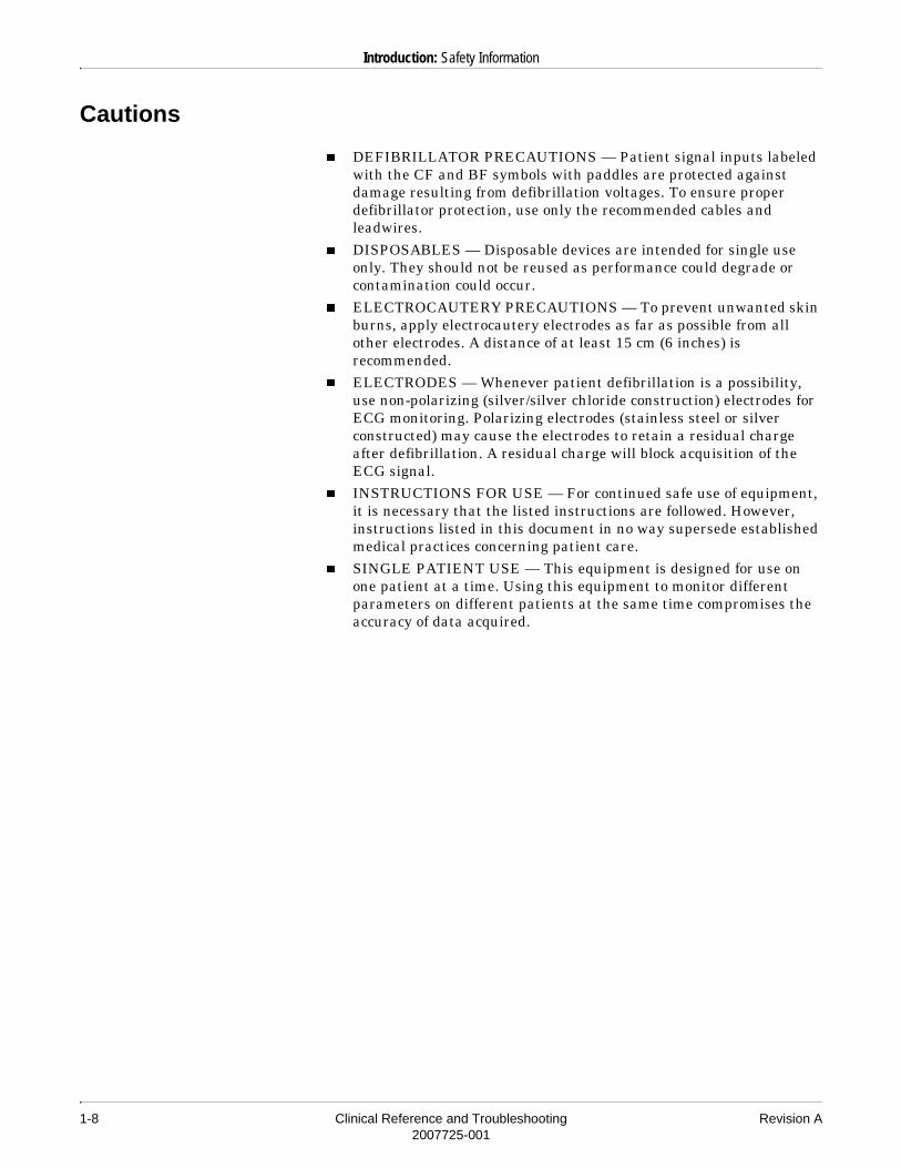
Cautions
� DEFIBRILLATOR PRECAUTIONS — Patient signal inputs labeled with the CF and BF symbols with paddles are protected against damage resulting from defibrillation voltages. To ensure proper defibrillator protection, use only the recommended cables and leadwires.
� DISPOSABLES — Disposable devices are intended for single use only. They should not be reused as performance could degrade or contamination could occur.
� ELECTROCAUTERY PRECAUTIONS — To prevent unwanted skin burns, apply electrocautery electrodes as far as possible from all other electrodes. A distance of at least 15 cm (6 inches) is recommended.
� ELECTRODES — Whenever patient defibrillation is a possibility, use non-polarizing (silver/silver chloride construction) electrodes for ECG monitoring. Polarizing electrodes (stainless steel or silver constructed) may cause the electrodes to retain a residual charge after defibrillation. A residual charge will block acquisition of the ECG signal.
� INSTRUCTIONS FOR USE — For continued safe use of equipment, it is necessary that the listed instructions are followed. However, instructions listed in this document in no way supersede established medical practices concerning patient care.
� SINGLE PATIENT USE — This equipment is designed for use on one patient at a time. Using this equipment to monitor different parameters on different patients at the same time compromises the accuracy of data acquired.

Revision A Clinical Reference and Troubleshooting 2-12007725-001
2 Calculation Programs

2-2 Clinical Reference and Troubleshooting Revision A2007725-001
For your notes
Revision A Clinical Reference and Troubleshooting 2-32007725-001
Calculation Programs: Introduction
Introduction
GE Medical Systems Information Technologies patient monitors have calculation programs to assist in the assessment and treatment of the critically ill patient. This chapter provides general information about cardiac calculations, pulmonary calculations, and dose calculations on GE Medical Systems Information Technologies monitors. For specific information about how to use these programs on a monitor, refer to the operator’s manual for a particular monitor.

2-4 Clinical Reference and Troubleshooting Revision A2007725-001
Calculation Programs: Cardiac Calculations
Cardiac Calculations
The cardiac calculations program displays important hemodynamic parameter values. These parameters are separated into two classifications: monitored parameters and calculated parameters.
Monitored Parameters
The monitored parameter values are obtained from available monitored patient data. Only weight and height values must be entered manually.
The table below shows the monitored parameters, the labels used to identify these parameters on the screen, and the units of measure.
Monitored Parameters
Parameter Label* Units
Cardiac Output CO L/MIN
Heart Rate HR BPM
Mean Arterial Pressure MAP mmHg
Central Venous Pressure CVP mmHg
Pulmonary Artery Mean PAM mmHg
Pulmonary Artery Wedge† PAW mmHg
Pulmonary Artery Diastolic† PAD mmHg
Left Atrial† LA mmHg
Weight WEIGHT kg or lbs
Height HEIGHT cm or inches
* The appearance of the label may vary depending on which GE Medical Systems Information Technologies patient monitor is being used (e.g., Weight vs. WEIGHT).† Menu selectable; only one is used at a time.

Revision A Clinical Reference and Troubleshooting 2-52007725-001
Calculation Programs: Cardiac Calculations
Calculated Parameters
The calculated parameter values are figured automatically. The table below shows the calculated parameters, the labels used to identify these parameters on the screen, the units of measure, and the formulas used.
Calculated Parameters
Parameter Label Unit Formula
Body Surface Area BSA m2 HT0.725 x WT0.425 x 0.007184
Cardiac Index CI L/min/m2
Stroke Volume SV mL/beat
Systemic Vascular Resistance SVR dyn·sec/cm5
Systemic Vascular Resistance Index
SVRI dyn·sec·m2/cm5 SVR x BSA
Pulmonary Vascular Resistance PVR dyn·sec/cm5
Pulmonary Vascular Resistance Index
PVRI dyn·sec·m2/cm5 PVR x BSA
Left Ventricular Stroke Work Index
LVSWI g·m/m2
Right Ventricular Stroke Work Index
RVSWI g·m/m2
* If using pulmonary artery diastolic (PAD) pressure or left atrial (LA) pressure, PAW is substituted with PAD or LA.
COBSA------------
COHR-------- 1000×
MAP CVP–( ) 79.92×CO
-------------------------------------------------------------
PAM PAW–( ) 79.92*×CO
------------------------------------------------------------------
SV MAP PAW–( )× 0.0136∗×BSA
-------------------------------------------------------------------------------------
SV PAM CVP–( )× 0.0136×BSA
--------------------------------------------------------------------------------
2-6 Clinical Reference and Troubleshooting Revision A2007725-001
Calculation Programs: Pulmonary Calculations
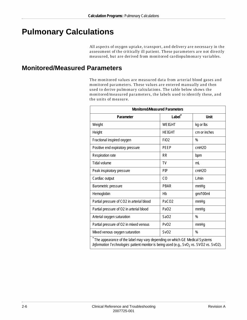
Pulmonary Calculations
All aspects of oxygen uptake, transport, and delivery are necessary in the assessment of the critically ill patient. These parameters are not directly measured, but are derived from monitored cardiopulmonary variables.
Monitored/Measured Parameters
The monitored values are measured data from arterial blood gases and monitored parameters. These values are entered manually and then used to derive pulmonary calculations. The table below shows the monitored/measured parameters, the labels used to identify these, and the units of measure.
Monitored/Measured Parameters
Parameter Label* Unit
Weight WEIGHT kg or lbs
Height HEIGHT cm or inches
Fractional inspired oxygen FiO2 %
Positive end expiratory pressure PEEP cmH2O
Respiration rate RR bpm
Tidal volume TV mL
Peak inspiratory pressure PIP cmH2O
Cardiac output CO L/min
Barometric pressure PBAR mmHg
Hemoglobin Hb gm/100ml
Partial pressure of CO2 in arterial blood PaCO2 mmHg
Partial pressure of O2 in arterial blood PaO2 mmHg
Arterial oxygen saturation SaO2 %
Partial pressure of O2 in mixed venous PvO2 mmHg
Mixed venous oxygen saturation SvO2 %
* The appearance of the label may vary depending on which GE Medical Systems Information Technologies patient monitor is being used (e.g., SvO2 vs. SVO2 vs. SvO2).

Revision A Clinical Reference and Troubleshooting 2-72007725-001
Calculation Programs: Pulmonary Calculations
Derived Pulmonary Calculations
The derived pulmonary calculation values are figured automatically. The table below shows the derived pulmonary calculations, the labels used to identify these on the screen, the units of measure, and the formulas used.
Derived Pulmonary Calculations
Parameter Label* Unit Formula
Body surface area BSA m2 HT0.725 x WT0.425 x 0.007184
Dynamic compliance Cdyn mL/cmH2O
Minute volume MV L/min
Cardiac index CI L/min/m2
Alveolar arterial oxygen gradient
AaDO2 mmHg PAO2 – PaO2
Arterial oxygen content CaO2 mL/100 mL
Oxygen delivery index DO2I mL/min/m2 CaO2 x CI x 10
Mixed venous oxygen content
CvO2 mL/100 mL
Arterial venous oxygen content difference
a–vO2 mL/100 mL CaO2 – CvO2
Oxygen consumption index
VO2I mL/min/m2 a–vO2 x CI x 10
Fick cardiac output FICK CO L/min
TVPIP PEEP–------------------------------
TV RR×1000
------------------------
COBSA-------------
Hb 1.39SaO2
100--------------××
PaO2 0.0031×( )+
Hb 1.39SvO2
100--------------××
PvO2 0.0031×( )+
VO2I BSA×CaO2 CvO2–( ) 10×
-------------------------------------------------------
2-8 Clinical Reference and Troubleshooting Revision A2007725-001
Calculation Programs: Pulmonary Calculations
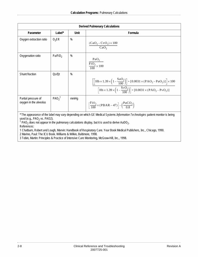
Oxygen extraction ratio O2ER %
Oxygenation ratio Pa/FiO2 %
Shunt fraction Qs/Qt %
Partial pressure of oxygen in the alveolus
PAO2† mmHg
* The appearance of the label may vary depending on which GE Medical Systems Information Technologies patient monitor is being used (e.g., PAO2 vs. PAO2).† PAO2 does not appear in the pulmonary calculations display, but it is used to derive AaDO2.References:1 Chatburn, Robert and Lough, Marvin: Handbook of Respiratory Care. Year Book Medical Publishers, Inc., Chicago, 1990.2 Marino, Paul: The ICU Book. Williams & Wilkin, Baltimore, 1998.3 Tobin, Martin: Principles & Practice of Intensive Care Monitoring, McGraw-Hill, Inc., 1998.
Derived Pulmonary Calculations
Parameter Label* Unit Formula
CaO2 CvO2–( ) 100×CaO2
----------------------------------------------------------
PaO2
FiO2
100------------- 100×------------------------------
Hb 1.39× 1SaO2
100--------------–
× 0.0031 PAO2 PaO2–( )×[ ]+ 100×
Hb 1.39× 1SvO2
100--------------–
× 0.0031 PAO2 PvO2–( )×[ ]+
--------------------------------------------------------------------------------------------------------------------------------------------------------------------------
FiO2
100------------- PBAR 47–( )×
PaCO2
0.8-------------------
–

Revision A Clinical Reference and Troubleshooting 2-92007725-001
Calculation Programs: Pulmonary Calculations
Estimated Pulmonary Calculations
When SpO2 and/or SvO2 are monitored by GE Medical Systems Information Technologies equipment and a hemoglobin value has been entered in the monitor, estimated pulmonary calculations can be obtained by the monitor at specified time intervals. The following table shows the estimated calculations, the labels, and the formulas used to obtain them. An “e” preceding a label indicates that it is an estimated value.
For details on obtaining and storing estimated pulmonary calculations, refer to the appropriate monitor operator’s manual.
Estimated Calculations Stored in Vital Signs
Estimated Parameter Label Formula Necessary Data
Arterial oxygen content eCaO2 SpO2, Hb
Mixed venous oxygen content eCvO2 SvO2, Hb
Arterial venous oxygen content difference ea–vO2 eCaO2 – eCvO2 SpO2, SvO2, Hb
Shunt fraction eQs/Qt SpO2, SvO2, Hb
Oxygen extraction ratio eO2ER SpO2, SvO2, Hb
Oxygen delivery index eDO2I eCaO2 x CI x 10 SpO2, Hb, CO
Oxygen consumption index eVO2I ea–vO2 x CI x 10 SpO2, SvO2, Hb, CO
Hb 1.39×( )SpO2
100---------------×
Hb 1.39×( )SvO2
100--------------×
Hb 1.39×( ) 1SpO2
100---------------–
× 100×
Hb 1.39×( ) 1SvO2
100--------------–
×------------------------------------------------------------------------------------
eCaO2 eCvO2–
eCaO2-------------------------------------------- 100×
2-10 Clinical Reference and Troubleshooting Revision A2007725-001
Calculation Programs: Dose Calculations
Dose Calculations
The intravenous administration of medications is a common practice. Many drugs are titrated based on the patient’s physiologic response to the medication. Accuracy and safety are always important in drug therapy, and precise control of drug administration is essential. The dose calculations feature is important because it provides an accurate and safe method of determining drug dosage.
An order for a medication is either written by the physician or is a standing protocol in the unit based on the patient’s condition. The order will specify the drug and the dose to be administered. The nurse and/or pharmacy will mix the drug in solution, and then determine how fast to administer the drug in order to deliver the proper drug dosage.
Neonates present a different approach to drug administration because the amount of fluid to be administered is vital. Usually, the drug dosage is ordered and the flow rate in cc/hr is prescribed. The nurse must determine the amount of drug to place in the solution in order to meet the rate/dose combination.
In other cases, the physician may order a drug dosage to be infused over a period of time. The amount of drug in solution may or may not be specified. In this situation, the nurse must determine the rate that is needed to infuse the proper drug dosage over the period of time ordered.
Still another situation occurs in cases where drugs are administered to resuscitate the patient, and then the dose is determined after the response. The clinician considers the solution volumes and drug quantities and the rate of the infusion to determine the dose that the patient is actually receiving.
The dose calculations program can be used in all of these situations. In addition, it also provides a titration table that can be used as the dosages are increased or decreased, based on the patient’s physiologic response. The titration table displays drug dosage information that can be used to help the clinician determine the dosing effects of intravenous pump setting and infusion rate changes.

Revision A Clinical Reference and Troubleshooting 2-112007725-001
Calculation Programs: Dose Calculations
The dose calculations program provides predefined libraries of commonly used drugs. One drug library is for adult and operating room monitor modes. The other drug library is for neonatal monitor mode. The following table lists the drugs available for each type of patient in the pre-defined lists. Drugs A through D can be used for drugs not specified in the library.
Common DrugsAdult and Operating
RoomNeonatal
Amiodarone X
Aminophylline X X
Diltiazem X
Dobutamine X X
Dopamine X X
Epinephrine X X
Fentanyl X
Heparin X X
Inocor X X
Insulin X X
Isuprel X
Lidocaine X
Midazolam X
Milrinone X
Morphine X
Neosynephrine X X
Nipride X
Nitroglycerin X
Norepinephrine X
Pitocin X
Procainamide X
Propofol X

2-12 Clinical Reference and Troubleshooting Revision A2007725-001
Calculation Programs: Dose Calculations
Prostaglandin E X
Tolazoline X
Vasopressin X
Vecuronium X X
Drug A X X
Drug B X X
Drug C X X
Drug D X X
Common DrugsAdult and Operating
RoomNeonatal

Revision A Clinical Reference and Troubleshooting 3-12007725-001
3 ECG

3-2 Clinical Reference and Troubleshooting Revision A2007725-001
For your notes

Revision A Clinical Reference and Troubleshooting 3-32007725-001
ECG: Introduction
Introduction
This chapter provides general information about monitoring ECG on GE Medical Systems Information Technologies monitors, including skin preparation, electrode placement, and arrhythmia analysis. For specific information about how to use these programs on a monitor, refer to the operator’s manual for a particular monitor.

3-4 Clinical Reference and Troubleshooting Revision A2007725-001
ECG: Skin Preparation
Skin Preparation
The quality of ECG information displayed on the monitor is a direct result of the quality of the electrical signal received at the electrode. Proper skin preparation is necessary for good signal quality at the electrode.
Choose flat, non-muscular areas to place electrodes, then follow the established prep protocol for your unit. Below is a suggested guideline for skin preparation:
1. Shave or clip hair from skin at chosen sites.
2. Gently rub skin surface at sites to remove dead skin cells.
3. Thoroughly cleanse the site with alcohol or a mild soap and water solution. Be sure to remove all oily residue, dead skin cells, and abrasives. Leftover abrasion particles can be a source of noise.
4. Dry the skin completely before applying the electrodes.
Regardless of patient age, all electrodes should be replaced on a regular basis, AT LEAST every 48 hours, to maintain quality signals during long-term monitoring. If they are not, increased noise can occur. Over the course of 48 hours, the electrode gel will start to dry out and the adhesive will age. After a long period of time, the patient’s skin may also be irritated by the gel or adhesive, causing discomfort.

Revision A Clinical Reference and Troubleshooting 3-52007725-001
ECG: Electrode Placement
Electrode Placement
The chart below shows the label used to identify each leadwire. Included also is its associated color code per AHA (American Heart Association) and IEC (International Electrotechnical Commission) standards.
Leadwire (Software Label) AHA Color AHA Label IEC Color IEC Label
RA (right arm) white RA red R
LA (left arm) black LA yellow L
RL (right leg) green RL black N
LL (left leg) red LL green F
V1 (precordial) brown V1 white C1
V2 (precordial) yellow V2 yellow C2
V3 (precordial) green V3 green C3
V4 (precordial) blue V4 brown C4
V5 (precordial) orange V5 black C5
V6 (precordial) purple V6 purple C6

3-6 Clinical Reference and Troubleshooting Revision A2007725-001
ECG: Electrode Placement
3-Leadwire Electrode Placement
When a 5-leadwire electrode configuration is not desirable, a 3-leadwire electrode configuration can be used.
Right arm and left arm electrodes should be placed just below the right and left clavicle.
Left leg electrode should be placed on a non-muscular surface on the lower edge of the rib cage.
3-Leadwire Configuration
The molded 3-leadwire sets can be placed in the 5-lead Multi-Link patient cable.
The standard molded 3- leadwire set is a selectable lead I, II, or III cable with a rotating reference (right arm, left arm, left leg). Using this standard cable with the monitor allows you to select one of three leads (I, II, or III) for monitoring ECG.
When using the standard 3-leadwire configuration, the following operating conditions occur:� Lead analysis automatically switches to single lead analysis. If an
attempt is made to change to multi-lead analysis, a message will appear briefly on the monitor, indicating that multi-lead analysis is not possible, and no change will occur.
� The choices for displayed leads are limited to I, II, and III.
3-Leadwire Electrode Placement (shown using AHA labels)
3-Leadwire Electrode Placement (shown using IEC labels)

Revision A Clinical Reference and Troubleshooting 3-72007725-001
ECG: Electrode Placement
� Any options usually allowing more than one ECG lead selection are disallowed.
� Respiration can be monitored from either lead I or II. It is not dependent on the displayed lead.
This 3-leadwire cable is not compatible with certain Tram modules. If this cable is connected to an incompatible Tram module, a message will be displayed on the monitor and a system warning alarm will sound.
����There is also an older style of 3-leadwire patient cables with a fixed reference:
� Lead I cable with a fixed right leg reference (right arm, left arm, left leg). Respiration is monitored from lead I only.
� Lead II cable with a fixed left arm reference (right arm, right leg, left leg). Respiration is monitored from lead II only.
Operation of the monitor with a fixed right leg reference is limited to the fixed lead designated. For example, if using a lead I cable, respiration is monitored from lead I. If the patient is not neonatal, multi-lead analysis defaults on. When using a 3-leadwire cable with a fixed reference, you should change lead analysis to single lead analysis, either in the defaults or on an individual patient basis.

3-8 Clinical Reference and Troubleshooting Revision A2007725-001
ECG: Electrode Placement
5-Leadwire Electrode Placement
Following is a suggested configuration when using five leadwires:
Right arm and left arm electrodes should be placed just below the right and left clavicle.
Right leg and left leg electrodes should be placed on a non-muscular surface on the lower edge of the rib cage.
The precordial electrode should be placed according to the physician’s preference.
5-Leadwire Electrode Placement (shown using AHA labels)
5-Leadwire Electrode Placement (shown using IEC labels)

Revision A Clinical Reference and Troubleshooting 3-92007725-001
ECG: Electrode Placement
6-Leadwire Electrode Configuration
A 6-leadwire electrode configuration can be used for telemetry monitoring with some telemetry transmitters. Refer to your equipment operator’s manual to determine if this option is available.
Right arm and left arm electrodes should be placed just below the right and left clavicle.
Right leg and left leg electrodes should be placed on a non-muscular surface on the lower edge of the rib cage.
For telemetry monitoring, any two precordial electrodes may be placed according to the physician’s preference.
����The V1 lead is recommended for arrhythmia detection, and the V5 lead is recommended for ST depression monitoring.*
* Barbara J. Drew, RN, PhD, FAAN (2000). Value of Monitoring a Second Precordial Lead for Patients in a Telemetry Unit, GE Medical Systems (order document number M04243ME0).
100ARL LL
RA
V1
LA
V5
101AN F
R
C1
L
C5
6-Leadwire Electrode Placement (shown using AHA labels)
6-Leadwire Electrode Placement (shown using IEC labels)

3-10 Clinical Reference and Troubleshooting Revision A2007725-001
ECG: Electrode Placement
10-Leadwire Electrode Configuration for 12SL Monitoring
�����To assure accurate 12-lead analysis when using a 10-leadwire patient cable, you must verify that the correct leadwire block is plugged into the appropriate side of the cable. The V2 through V6 leadwire block is color coded brown.
A suggested electrode configuration for traditional monitoring, and an alternate, traditional cardiology configuration are shown below.
����For the most accurate serial comparisons, use the same electrode configuration as used on prior analyses for the patient.
Traditional Monitoring Electrode Configuration
(shown using AHA labels)
Traditional Cardiology Electrode Configuration
(shown using AHA labels)
Revision A Clinical Reference and Troubleshooting 3-112007725-001
ECG: Electrode Placement
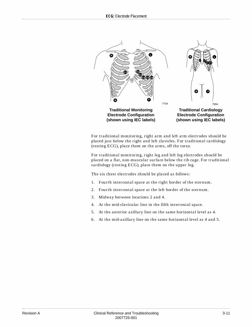
For traditional monitoring, right arm and left arm electrodes should be placed just below the right and left clavicles. For traditional cardiology (resting ECG), place them on the arms, off the torso.
For traditional monitoring, right leg and left leg electrodes should be placed on a flat, non-muscular surface below the rib cage. For traditional cardiology (resting ECG), place them on the upper leg.
The six chest electrodes should be placed as follows:
1. Fourth intercostal space at the right border of the sternum.
2. Fourth intercostal space at the left border of the sternum.
3. Midway between locations 2 and 4.
4. At the mid-clavicular line in the fifth intercostal space.
5. At the anterior axillary line on the same horizontal level as 4.
6. At the mid-axillary line on the same horizontal level as 4 and 5.
Traditional Monitoring Electrode Configuration (shown using IEC labels)
Traditional Cardiology Electrode Configuration (shown using IEC labels)

3-12 Clinical Reference and Troubleshooting Revision A2007725-001
ECG: Electrode Placement
Electrode Placement for Neonates
Because neonatal patients are small, there is usually only enough room for a 3-leadwire electrode configuration. A 3-lead neonatal ECG cable is available, and Multi-Link DIN adapter is available for the 5-lead Multi-Link cable. The right arm and left arm or right arm and left leg electrodes are positioned on the right and left sides of the chest. The third electrode (right leg) can be placed on either the right or left side of the abdomen.
Lead II Lead I Lead II Lead I
Neonatal Electrode Placement (shown using AHA labels)
Neonatal Electrode Placement (shown using IEC labels)

Revision A Clinical Reference and Troubleshooting 3-132007725-001
ECG: Electrode Placement
Electrode Placement for Pacemaker Patients
Electrodes need to be repositioned to modify detection of the electrical signals generated by the pacemaker. Following is a suggested configuration.
����When using this configuration, display lead II as the primary ECG lead.
The right arm electrode is moved down to the fifth intercostal space, and the left leg electrode is moved up to the fifth intercostal space.
����After all electrodes are in place, ensure that a minimum of 1/2 mV of signal is present on each lead (I, II, III, V) for beat detection to occur.
Pacemaker Electrode Placement (shown using AHA labels)
Pacemaker Electrode Placement (shown using IEC labels)

3-14 Clinical Reference and Troubleshooting Revision A2007725-001
ECG: Electrode Placement
Maintaining Quality ECG Signal
Stabilize the electrode and leadwire with a leadwire stress loop near the electrode. Tape the stress loop to the patient. A secured stress loop prevents leadwire rotation about the electrode snap, leadwire tugging at the electrode, and ECG artifact.
Regardless of patient age, electrodes should be replaced AT LEAST every 48 hours to maintain quality signals during long-term monitoring. Over the course of 48 hours, the electrode gel will start to dry out and the adhesive will age. After a long period of time, the patient’s skin may also be irritated by the gel or adhesive, causing discomfort.
Electrosurgical Unit (ESU) Cable
The Multi-Link ESU ECG patient cable may be used when using the monitor in the presence of an electrosurgical unit. This cable, with a built-in ESU filter, helps reduce electrosurgical noise detected on the ECG signal.
Revision A Clinical Reference and Troubleshooting 3-152007725-001
ECG: Pacemaker Detection
Pacemaker Detection
Safety Considerations
Be aware of the following when monitoring a patient with a pacemaker.
Warnings
� FALSE CALLS — False low heart rate indicators or false asystole calls may result with certain pacemakers because of electrical overshoots. Keep pacemaker patients under close observation.
� MONITORING PACEMAKER PATIENTS — Monitoring of pacemaker patients can only occur with the pace program activated. Turn on pacemaker detection when monitoring a patient with a pacemaker.
� PACEMAKER SPIKE — An artificial pacemaker spike is displayed in place of the actual pacemaker spike. All pacemaker spikes appear uniform. Do not diagnostically interpret pacemaker spike size and shape.
� PATIENT HAZARD — A pacemaker pulse can be counted as a QRS during asystole when pacemaker mode is activated. Keep pacemaker patients under close observation.
� RATE METERS — Keep pacemaker patients under close observation. Rate meters may continue to count the pacemaker rate during cardiac arrest and some arrhythmias. Therefore, do not rely entirely on rate meter alarms.

3-16 Clinical Reference and Troubleshooting Revision A2007725-001
ECG: Pacemaker Detection
Caution
�� ���FDA POSTMARKET SAFETY ALERT — The United States FDA Center for Devices and Radiological Health issued a safety bulletin October 14, 1998. This bulletin states “that minute ventilation rate-adaptive implantable pacemakers can occasionally interact with certain cardiac monitoring and diagnostic equipment, causing the pacemakers to pace at their maximum programmed rate.”
The FDA further recommends precautions to take into consideration for patients with these types of pacemakers. These precautions include disabling the rate responsive mode and enabling an alternate pace mode (when available on the monitor). For more information contact:
Office of Surveillance and Biometrics, CDRH, FDA1350 Piccard Drive, Mail Stop HFZ-510Rockville, MD 20850U.S.A.
Note
����ECG monitoring with patients on non-invasive transcutaneous pacemakers may not be possible due to large amounts of energy produced by these devices. Monitoring ECG with an external device (e.g., a defibrillator and a second set of electrodes) may be needed. Remember that there are no ECG alarms at the monitor if you are monitoring with an external device.

Revision A Clinical Reference and Troubleshooting 3-172007725-001
ECG: Pacemaker Detection
Monitoring Pacemaker Patients
Pacemaker detection must be turned on at the monitor. It must be used whenever the monitored patient has a pacemaker. Refer to your monitor operator’s manual for instructions on how to turn pacemaker detection on and off.
It is important to read all information in your monitor operator’s manual regarding pacemaker detection. The information below provides general guidelines and information about pacemaker detection algorithms. It does NOT explain how to use pacemaker detection on your monitor. You must refer to the operator’s manual for this.
There are two different algorithms for pacemaker artifact rejection. The clinician must be the judge as to which mode (algorithm) is better for each patient.
The Pace 2 mode is much more conservative in recognizing paced QRS morphologies and is recommended for use whenever possible. It is designed to minimize the possibility of counting pacemaker artifact as QRS complexes during asystole.
The Pace 2 mode analyzes waveforms with the added capability of minimizing the chance of counting severe residual pacemaker energy as QRS complexes. In relation to the event rejection capability of the Pace 2 mode, certain morphologies may not be detected. Arrhythmia calls like asystole or pause may be made with heart rate identified as less than actual.
If the monitor does not adequately detect paced beats in the Pace 2 mode, then you may wish to try the Pace 1 mode.
����Observe all cautions as described when choosing the Pace 1 mode of observation.
The Pace 1 mode allows successful detection of the largest variety of paced QRS morphologies. As a direct consequence, this mode does have a higher risk of counting pacemaker artifact as QRS complexes during asystole. For this reason, it is imperative to keep patients with pacemakers under close observation. It is also recommended that you set the low heart rate limit on the monitor close to the minimum pacing rate, and that you elevate the bradycardia arrhythmia alarm level to a Warning or Crisis level.

3-18 Clinical Reference and Troubleshooting Revision A2007725-001
ECG: Pacemaker Detection
The Pace 1 mode analyzes the presence of a pacemaker spike, assesses the waveform for residual pacemaker energy, and determines the presences of an R wave following the pacemaker spike. If an event occurs during the first few milliseconds following the pacemaker spike, it will be counted.
When a pace mode is enabled, the software places an artificial spike on the waveform whenever the pacemaker triggers. When pacemaker detection is turned on, it is indicated on the monitor display.
Follow these suggestions to successfully monitor pacemaker patients:� Use recommended electrode placement. Refer to “Electrode
Placement” on page 3-5.� Brady, Pause, and Low Heart Rate are additional alarms available
for use when monitoring pacemaker patients.� Problems you may experience include:
� heart rate double counting� inaccurate alarms for low heart rate or asystole� pacemaker spikes not recognized by the software
� Possible solutions to the above problems include:� relearn arrhythmia� try an alternate electrode placement� try single-lead analysis, if available� try switching to the other pacemaker detection mode
� Pacemaker mode: In most cases, Pace 2 mode effectively monitors a pacemaker patient. However, if you experience problems, select the Pace 1 mode as an option and observe all cautions as described for the Pace 1 mode of operation.
For more information, refer to “Pacemaker Troubleshooting” on page 3-26.

Revision A Clinical Reference and Troubleshooting 3-192007725-001
ECG: Arrhythmia Analysis
Arrhythmia Analysis
�����VENTRICULAR ARRHYTHMIAS — The arrhythmia analysis program is intended to detect ventricular arrhythmias. It is not designed to detect atrial or supraventricular arrhythmias. Occasionally it may incorrectly identify the presence or absence of an arrhythmia. Therefore a physician must analyze the arrhythmia information in conjunction with other clinical findings.
����Some monitors offer atrial fibrillation detection (AFIB). When the atrial fibrillation arrhythmia detection feature is present, it replaces the irregular arrhythmia alarm text with the atrial fibrillation alarm text.
�����SUSPENDED ANALYSIS — Certain conditions suspend arrhythmia analysis. When suspended, arrhythmia conditions are not detected and alarms associated with arrhythmias do not occur. Conditions causing suspended arrhythmia analysis include arrhythmia off, arrhythmia suspended, leads fail, alarm pause, all alarms off, and discharged patient.
Lethal Arrhythmia Analysis
Lethal arrhythmia analysis calls limited arrhythmias. The lethal arrhythmias are Asystole, VFib/VTac, and V Tach, except when the patient is neonatal (e.g., monitor is in neonatal mode or patient age is neonatal). When the patient is neonatal, Asystole, VFib/VTac, and Brady are the lethal arrhythmias.
Refer to “Arrhythmia Conditions” on page 3-20 for arrhythmia definitions.

3-20 Clinical Reference and Troubleshooting Revision A2007725-001
ECG: Arrhythmia Analysis
Full Arrhythmia Analysis
Full arrhythmia analysis expands the number of arrhythmias that the monitor detects. Refer to the complete list in “Arrhythmia Conditions”.
Full arrhythmia analysis includes a premature ventricular contractions (PVC) per minute alarm. The number of PVCs detected over the last minute is displayed in the monitor’s ECG window.
Arrhythmia Conditions
Following is an alphabetical list of the arrhythmia messages that are displayed when full arrhythmia analysis is turned on and the condition occurs. Definitions of each condition are included.
The monitor’s response to each condition is determined by the alarm level to which the arrhythmia has been assigned. Refer to your monitor operator’s manual for more information.
ACC VENT Adult — Accelerated ventricular occurs when six or more ventricular beats are detected with an average heart rate for the ventricular beat between 50 and 100 beats per minute.
11-13 years — Occurs when six or more ventricular beats are detected with an average heart rate for the ventricular beat between 60 and 130 beats per minute.
3-10 years — Occurs when six or more ventricular beats are detected with an average heart rate for the ventricular beat between 60 and 140 beats per minute.
0-2 years — Occurs when six or more ventricular beats are detected with an average heart rate for the ventricular beat between 60 and 160 beats per minute.
AFIB Characterized by random, chaotic, low-amplitude deflections of the supraventricular component of the ECG waveform, resulting in irregular timing of QRS complexes and an absence of uniform P waves preceding the QRS complex.
����Not available on some monitors.
ASYSTOLE Ventricular asystole occurs whenever the displayed heart rate drops to zero.
Revision A Clinical Reference and Troubleshooting 3-212007725-001
ECG: Arrhythmia Analysis
BIGEMINY Occurs when three or more bigeminal cycles (a ventricular beat followed by a non-ventricular beat) are detected.
BRADY Bradycardia is the average of the most recent eight R-to-R intervals at a heart rate less than the set LOW heart rate limit.
����The Brady limit matches the low heart rate limit. If the low heart rate limit is changed, the Brady limit changes.
COUPLET Occurs when two ventricular beats are detected and have non-ventricular beats before and after the couplet. The coupling interval must be less than 600 milliseconds.
IRREGULAR Occurs when six consecutive normal R-to-R intervals vary by 100 milliseconds or more.
����Not used if AFIB is enabled.
PAUSE Occurs when a 3-second interval without a QRS complex is detected.
����The pause interval is adjustable on certain monitors. Refer to the operator’s manual for details.
PVC Isolated premature ventricular complexes occur when a premature ventricular beat is detected and has non-ventricular beats before and after.
R ON T Occurs when a ventricular complex is detected within the repolarization period of a non-ventricular beat.
TACHY Tachycardia is four R-to-R intervals at a heart rate greater than the set HIGH heart rate limit.
����The Tachy limit matches the high heart rate limit. If the high heart rate limit is changed, the Tachy limit changes.
TRIGEMINY Occurs when three or more trigeminal cycles (a ventricular beat followed by two non-ventricular beats) are detected.
VBRADY Adult — Ventricular bradycardia occurs when a run of three or more ventricular beats is detected with an average heart rate that is less than or equal to 50 beats per minute.

3-22 Clinical Reference and Troubleshooting Revision A2007725-001
ECG: Arrhythmia Analysis
0 to 13 years — Occurs when a run of three or more ventricular beats is detected with an average heart rate that is less than or equal to 60 beats per minute.
VFIB/VTAC Ventricular fibrillation occurs when the ECG waveform indicates a chaotic ventricular rhythm.
�����VFIB/VTAC should not be considered a substitute for the V TACH arrhythmia call. Efforts to lower the V TACH alarm level can result in missed ventricular tachycardia alarms.
V TACH Adult — Ventricular tachycardia occurs when a run of six or more ventricular beats is detected with an average heart rate greater than or equal to 100 beats per minute.
11-13 years — Occurs when a run of six or more ventricular beats is detected with an average heart rate greater than or equal to 130 beats per minute.
3-10 years — Occurs when a run of six or more ventricular beats is detected with an average heart rate greater than or equal to 140 beats per minute.
0-2 years — Occurs when a run of six or more ventricular beats is detected with an average heart rate greater than or equal to 160 beats per minute.
VT > 2 Adult — Ventricular tachycardia >2 occurs when a run of ventricular beats is detected with a duration of less than six beats but longer than two beats and with an average heart rate that is greater than or equal to 100 beats per minute.
11-13 years — Occurs when a run of ventricular beats is detected with a duration of less than six beats but longer than two beats and with an average heart rate that is greater than or equal to 130 beats per minute.

Revision A Clinical Reference and Troubleshooting 3-232007725-001
ECG: Arrhythmia Analysis
3-10 years — Occurs when a run of ventricular beats is detected with a duration of less than six beats but longer than two beats and with an average heart rate that is greater than or equal to 140 beats per minute.
0-2 years — Occurs when a run of ventricular beats is detected with a duration of less than six beats but longer than two beats and with an average heart rate that is greater than or equal to 160 beats per minute.

3-24 Clinical Reference and Troubleshooting Revision A2007725-001
ECG: Troubleshooting
Troubleshooting
Problem: Why is the monitor alarming for asystole, bradycardia, pause, or inaccurate heart rate when a visible QRS waveform is present?
Solution: The monitor may not be detecting sufficient QRS amplitude in all analyzed leads. Multiple leads (I, II, III, and V) are used for arrhythmia processing.
Check the ECG signal acquired from the patient.
1. View all ECG leads to assess the amplitude of the QRS complexes. A minimum of 0.5 mV amplitude in all analyzed ECG waveforms at normal size is required for QRS detection. For best results, an amplitude of 1.0 mV in all analyzed leads is recommended. Amplitude is viewed in one direction (positive or negative). For borderline signals, validate the ECG waveform on a graph.
2. If the amplitude is low in any of the analyzed leads, reprep the patient’s skin, replace electrodes, and adjust the electrode placement.
� Amplitude can be adjusted by moving the leads closer to the source of conduction (the heart).
� Using the ECG size option on the monitor to increase the size of the waveform does not affect ECG analysis. It is for viewing purposes only.
� It may be beneficial to move V lead electrodes (chest lead) to alternate precordial electrode placements to improve detection.
Relearn arrhythmia. It is important to relearn the patient’s ECG pattern any time the electrode configuration is adjusted. Refer to your monitor operator’s manual for details on how to use the relearn option on the monitor. Remember to ensure that there is a clean ECG signal displayed before relearning.
If the problem continues, determine the lead with the greatest amplitude, display that lead, then switch to single lead analysis so all arrhythmia interpretations are based on this single ECG lead. Refer to your monitor operator’s manual for details.

Revision A Clinical Reference and Troubleshooting 3-252007725-001
ECG: Troubleshooting
Problem: Why is the monitor calling VTach when the patient is not in VTach?
Solution: The monitoring system may be detecting a wider QRS complex or artifact in some of the analyzed ECG waveforms. In addition, the V leads may be exhibiting polarity changes, which may occasionally cause an inaccurate call.
Check the ECG signal acquired from the patient.
1. View all ECG leads to assess the width of the QRS complexes in the analyzed leads (I, II, III, and V).
2. If artifact exists in any of the analyzed leads, reprep the patient’s skin, replace electrodes, and adjust the electrode placement.
3. It may be beneficial to move V lead electrodes (chest lead) to alternate precordial electrode placements to improve detection.
Relearn arrhythmia. It is important to relearn the patient’s ECG pattern any time the electrode configuration is adjusted. Refer to your monitor operator’s manual for details on how to use the relearn option on the monitor. Remember to ensure that there is a clean ECG signal displayed before relearning.
If the problem continues, determine the lead with the narrowest QRS complex, display that lead, then switch to single lead analysis so all arrhythmia interpretations are based on this single ECG lead. Refer to your monitor operator’s manual for details.
Problem: What does the Arrhy Suspend message mean?
Solution: Certain conditions suspend arrhythmia analysis. When suspended, arrhythmia conditions are not detected and alarms associated with arrhythmias do not occur. This alarm signals that 20 of the last 30 seconds of the ECG data is of poor quality and arrhythmia interpretation is suspended. It generates a continuous alarm until the quality of the ECG signal improves. To resume arrhythmia processing and alarms, this issue must be resolved.
1. Check lead placement.
2. Perform skin preparation.
3. Replace electrodes or adjust electrode placement.

3-26 Clinical Reference and Troubleshooting Revision A2007725-001
ECG: Troubleshooting
Problem: What is the specific criteria for the different arrhythmia conditions?
Solution: EK-Pro is the arrhythmia interpretation program used by GE Medical Systems Information Technologies monitors. Arrhythmia criteria is pre-defined. See “Arrhythmia Analysis” on page 3-19 for definitions of the various arrhythmia calls.
Pacemaker Troubleshooting
Also refer to “Pacemaker Detection” on page 3-15, as well as the pacemaker monitoring section your monitor operator’s manual, for more information.
There are two general things that occur when pacemaker detection is activated for pacemaker patients:
1. Beats that would otherwise be classified as ventricular are instead classified as V-paced if a ventricular pacemaker event is detected.
2. Residual pacemaker energy that might otherwise appear in the ECG is removed, and a pacemaker enhanced spike is placed in the ECG.
Pacemaker detection is indicated visually in the ECG window. On the ECG waveform, pacemaker detection is indicated by uniform, upright pacemaker enhancement spikes in the ECG data, both displayed and graphed.
Two effective approaches for improving pacemaker detection are:� Change the primary displayed ECG trace to a different lead.
����If your system uses multi-vector pacemaker detection, the above statement is not effective since two leads are used to detect pace.
� Move the electrodes associated with the primary displayed trace.
Pacemaker patients should be kept under close observation.
Problem: Why is the monitor double-counting the heart rate, alarming for a low heart rate, or not detecting pacemaker spikes?
Solution: The monitor is not detecting pacemaker activity. Causes may include:� The pacemaker detection program is turned off.� The pacemaker signal is too weak for the monitor to detect.� The ECG signal is too weak for the monitor to detect.

Revision A Clinical Reference and Troubleshooting 3-272007725-001
ECG: Troubleshooting
� The monitor is detecting atrial pacemaker artifact or non-QRS features as beats.
First, ensure that pacemaker detection is turned on. Refer to your monitor operator’s manual for instructions on enabling pacemaker detection.
After you have verified that pacemaker detection is on, if the monitor still does not detect pacemaker activity, reprep the skin and reposition the electrodes. (Refer to “Electrode Placement for Pacemaker Patients” on page 3-13.) The V lead can be repositioned to any one of the precordial sites. Then relearn ECG. (Refer to your monitor operator’s manual for instructions.)
If the monitor is alarming for low heart rate or asystole, assess the QRS amplitude. View all ECG. A minimum of 0.5 mV of amplitude in one direction (positive or negative) is required in all analyzed leads for proper QRS detection. If necessary, reprep the skin and reposition the electrodes. Then relearn ECG. (Refer to your monitor operator’s manual for instructions.)
If the monitor is still not detecting pacemaker activity, adjust the pacemaker detection mode. Pace 1 is an alternate if Pace 2 does not adequately detect pacemaker activity. For low heart rate, use Pace 1 mode. For high heart rate, use Pace 2 mode. Refer to your monitor operator’s manual and “Pacemaker Detection” on page 3-15 for more information.

3-28 Clinical Reference and Troubleshooting Revision A2007725-001
ECG: Troubleshooting
For your notes

Revision A Clinical Reference and Troubleshooting 4-12007725-001
4 Invasive Blood Pressures

4-2 Clinical Reference and Troubleshooting Revision A2007725-001
For your notes

Revision A Clinical Reference and Troubleshooting 4-32007725-001
Invasive Blood Pressures: Introduction
Introduction
This chapter provides general clinical information about monitoring invasive blood pressures on a GE Medical Systems Information Technologies monitor. For specific information about monitoring invasive blood pressures on a particular monitor, refer to your monitor operator’s manual.

4-4 Clinical Reference and Troubleshooting Revision A2007725-001
Invasive Blood Pressures: Assigned Pressure Names
Assigned Pressure Names
Each invasive pressure on the acquisition modules is labeled BP. For convenience, the monitor assigns a specific pressure name to each connector. These names can be changed so that any pressure line can be plugged into any invasive pressure connector. Having the connector names properly reflect the sites is important for proper waveform processing, since different algorithms are used for processing different pressure sites.
The site names supported and values displayed are:� arterial (ART) — systolic, diastolic, and mean� femoral (FEM) — systolic, diastolic, and mean� pulmonary artery (PA) — systolic, diastolic, and mean� central venous (CVP) — mean� left atrial (LA) — mean� right atrial (RA) — mean� intracranial (ICP) — mean� special (SP) — mean
Additional sites available for neonatal patients are:� umbilical artery catheter (UAC) — systolic, diastolic, and mean� umbilical venous catheter (UVC) — mean
The following table shows the pressures assigned to the pressure connectors on the Tram modules. For reference purposes, the connectors are referred to as BP1, BP2, etc., beginning with the left-most connector.
Assigned BP Names for Tram Modules
BP1 BP2 BP3 BP4
Tram modules with 2 BP connectors
ART PA — —
Tram modules with 3 BP connectors
ART PA CVP —
Tram modules with 4 BP connectors*
ART PA CVP LA
* Or, fourth BP when using a Tram 451 series module with the split BP3/BP4, Y-adapter cable plugged into the third BP connector

Revision A Clinical Reference and Troubleshooting 4-52007725-001
Invasive Blood Pressures: Assigned Pressure Names
Separate BP modules residing in the third slot of the Tram-rac housing are assigned as CVP and LA pressures. Separate BP modules residing in the fourth slot of the Tram-rac housing are assigned as ICP and SP pressures.
The Y-adapter cable can also be used with a Dash 3000/4000 patient monitor. If plugged into port 1 it is labeled BP1/BP3, if it is plugged into the second port it is labeled BP2/BP4.

4-6 Clinical Reference and Troubleshooting Revision A2007725-001
Invasive Blood Pressures: IABP
IABP
����The intra-aortic balloon pump (IABP) feature is NOT available for neonatal patients.
Triggering
IMPORTANT — GE Medical Systems Information Technologies recommends that the signal source used to trigger an intra-aortic balloon pump should be the balloon pump itself. This insures that the trigger signal is compatible with all modes of the IABP. An extra set of ECG electrodes or an additional connection from the arterial line can be connected to the monitor to produce waveforms on the monitor’s display for consolidated viewing.
�����PATIENT HAZARD — If you choose to trigger the balloon pump from the monitor, contact the balloon pump manufacturer directly for interface requirements, as they vary among manufacturers.
Some trigger modes on certain balloon pump devices may not be compatible with GE Medical Systems Information Technologies’ analog output signal, and use may contribute to patient injury or sub-optimal pumping results.
If you choose to use the monitor for triggering, you must follow the instructions below. Failure to follow these instructions may result in an incompatible analog output signal, which may contribute to patient injury.
1. Contact the balloon pump manufacturer for interface requirements. Refer to your monitor operator’s manual for the GE Medical Systems Information Technologies’ ECG analog output delay specification for your monitor’s acquisition device.

Revision A Clinical Reference and Troubleshooting 4-72007725-001
Invasive Blood Pressures: IABP
2. Cable connection and ECG filter.
Use the appropriate compatible analog output cable from GE Medical Systems Information Technologies.
Cable the balloon pump to the monitor through the Defib Sync connector on the acquisition module.
3. Primary displayed ECG lead. If the balloon pump triggers off the R wave of the ECG, review the patient’s ECG leads and place the one with the greatest amplitude in the top (primary) position on the monitor display.
4. Pacemaker detection. If the patient has a pacemaker, be sure pacemaker detection is turned on. (Refer to your monitor operator’s manual for details.) Failure to turn pacemaker detection ON may cause poor beat detection, which may result in inadequate triggering of the balloon pump.
5. BP filter. If blood pressure is used to trigger the balloon pump, use the 40 Hz pressure filter. (Refer to your monitor operator’s manual for details.)
Displayed Values
Displayed pressure values are affected by the intra-aortic balloon pump.
The IABP program displays three values, for example 150/45 (98). The first value is the systolic value, the second is the diastolic value, and the third is the mean.
The displayed numeric values are computing a rapidly varying waveform generated during IABP treatment and do not always reflect a true arterial pressure. For accuracy and reliability, always combine two or more of the recommended methods listed below for reading arterial and/or femoral blood pressure:� the IABP waveform displayed on the screen (use scales for
evaluation),� a printed copy of the waveform (use scales for evaluation), or� the balloon pump device’s display, if available.
Since there are a number of points along the IABP waveform that could be the displayed value, it is important to know which points the program uses. The values displayed will differ depending on the timing of the pump.

4-8 Clinical Reference and Troubleshooting Revision A2007725-001
Invasive Blood Pressures: IABP
For 1:1 or 1:2 Timing:
Systolic Numerics� When the augmented diastole is greater than the patient systole, the
displayed systole equals the augmented diastole (see figure 1).� When the patient systole is greater than the augmented diastole, the
displayed systole equals the patient systole (see figure 2).
Diastolic Numerics� The displayed diastole always equals the balloon end diastole (see
figures below).
Figure 1: Augmented Diastole > Patient Systole
Figure 2: Patient Systole > Augmented Diastole
ART 134/63 ART 160/45

Revision A Clinical Reference and Troubleshooting 4-92007725-001
Invasive Blood Pressures: IABP
For 1:3 or More Timing:
Systolic Numerics� The displayed systolic numerics switch between the augmented
diastole and patient systole (see figure 3).
Diastolic Numerics� The displayed diastole switches between the balloon end diastole and
the patient end diastole (see figure 3).
Figure 3
Displayed values will switch between:ART 123/51 (�) and ART 100/60 (�)
4-10 Clinical Reference and Troubleshooting Revision A2007725-001
Invasive Blood Pressures: Smart BP
Smart BP
����The Smart BP feature is not available for neonatal patients.
Smart BP is an arterial (femoral) artifact rejection program that substantially reduces the occurrences of needless alarms by eliminating most of the alarms associated with zeroing the transducer, fast flushing the system, and drawing blood.
When Smart BP is on and the system recognizes one of these events, the arterial (femoral) alarms are deactivated and the systolic and diastolic numerics are replaced with Xs. The message “ARTIFACT” is displayed. The mean pressure value is displayed throughout the artifact occurrence.
Safety Features: If zeroing, fast flushing, or drawing blood is not accomplished within certain time frames, alarms will sound. When artifact is detected, Smart BP begins to search for the return of a pulsatile pressure. When 15-20 beats have been detected, numerics are displayed and alarms are reactivated. If pressure remains below 10 mmHg for more than 14 seconds, the alarms will reactivate. During sustained high pressure (drawing blood), you have a maximum of two minutes before alarms reactivate.

Revision A Clinical Reference and Troubleshooting 4-112007725-001
Invasive Blood Pressures: Disconnect Alarm
Disconnect Alarm
The Disconnect Alarm feature is found in the ART and FEM pressure menus.
����This feature is not available when the monitor is set for Neonatal-ICU mode.
If the mean pressure falls below 25 mmHg and the disconnect alarm feature is on, a warning alarm sounds and the message “DISCONNECTED” is displayed in the values window. The parameter name also appears in this message. Check your patient immediately in the event the catheter has dislodged.
To turn this feature on and off, select DISCONNCT ALARM from the appropriate pressure menu. This feature can be set in monitor defaults. The alarm level cannot be changed — it is always a warning alarm.

4-12 Clinical Reference and Troubleshooting Revision A2007725-001
Invasive Blood Pressures: Troubleshooting
Troubleshooting
Problem: Displayed pressure values are different than expected.
Solution:� Check the patient. Values could be valid, the patient could be lying
on the tubing, or the tubing could be kinked.� Check tubing for bubbles.� Remove excess tubing.� Check phlebostatic axis placement of transducer.� Rezero pressure. � Is patient on IABP? If so, verify that the monitor’s IABP program is
turned on. If necessary, turn it on. (Refer to your monitor operator’s manual.)
Problem: Smart BP is on. Artifact is sensed without flush, draw, or zero.
Solution: Turn Smart BP off, then on again. If the problem persists, you may need to disable Smart BP by turning it off for that pressure.
Use your monitor’s alarm pause feature prior to drawing blood to reduce unnecessary alarms if Smart BP is disabled.
Problem: The arterial, noninvasive (oscillometric), and auscultated blood pressure readings are indicating different values.
Solution: The three measurement methods use different technologies. Auscultation and oscillometric are both indirect methods of measuring blood pressure. In auscultation, changes in arterial sounds during cuff deflation are related to systolic and diastolic pressure. With oscillometric measurement, changes in measured pressure oscillations during cuff deflation are related to systolic, mean and diastolic pressures. Changes in the vascular tone of the arterial system can cause these two indirect methods to differ from one another and from direct arterial pressure measurements.
Invasive arterial blood pressure is a direct method of measuring blood pressure. Differences between direct and indirect blood pressure measurements are expected. These differences occur because direct methods measure pressure and indirect methods measure flow. In addition, differences occur because the measurement location is not the same, e.g., brachial artery for NBP vs. radial artery for invasive arterial pressure monitoring.

Revision A Clinical Reference and Troubleshooting 4-132007725-001
Invasive Blood Pressures: Troubleshooting
Problem: The monitor is alarming for arterial disconnect.
Solution: Check the patient immediately in the event the catheter has been dislodged.
The arterial disconnect alarm is turned on. If the mean pressure falls below 25 mmHg and the disconnect alarm is on, the monitor alarms. When zeroing the pressure line, the clinician has 14 seconds to complete the process. After that time the disconnect alarm is activated.
If zeroing, close the stopcock. Once the monitor detects the return of waveform and numeric data, the alarm will reset.
The disconnect alarm can be turned off. Refer to your monitor operator’s manual for instructions. Remember to monitor the patient closely if you turn this alarm off.
Wedge Troubleshooting
Problem: Unable to detect PA wedge.
Solution: Use the manual method for PA wedge measurement. Refer to your monitor operator’s manual for instructions.
Problem: The monitor displays a message indicating that it is processing the wedge when the balloon has not been inflated.
Solution: Begin wedge processing again. If a wedge is again detected due to respiratory artifact on the PA waveform, use the manual method for wedge measurement. Refer to your monitor operator’s manual for instructions.
Problem: The monitor displays the inflate balloon message after the balloon was inflated.
Solution: The monitor must detect a 30% decrease in waveform amplitude to initiate a wedge. If the waveform does not change accordingly, the message will continue to be displayed.

4-14 Clinical Reference and Troubleshooting Revision A2007725-001
Invasive Blood Pressures: Troubleshooting
Problem: The displayed wedge measurement is different than expected.
Solution:� Repeat the wedge measurement, allowing a minimum of three
respiratory cycles of data.� Verify end-expiration using the respiratory waveform on the display
and observing the patient’s breathing pattern. (Some monitors display vertical cursors to help identify the end-expiration and align it with the PA pressure waveform.)
� Adjust the PA wedge cursor to the end-expiratory wedge value if necessary. Refer to your monitor operator’s manual for instructions.

Revision A Clinical Reference and Troubleshooting 5-12007725-001
5 Noninvasive Blood Pressure

5-2 Clinical Reference and Troubleshooting Revision A2007725-001
For your notes

Revision A Clinical Reference and Troubleshooting 5-32007725-001
Noninvasive Blood Pressure: Introduction
Introduction
A patient’s vital signs may vary dramatically during the use of cardiovascular agents such as those that raise or lower blood pressure or those that increase or decrease heart rate.
Because treatment protocol based on the patient’s blood pressure may rely on specific values and differing measurement methods, clinicians should note a possible variance from values obtained with this monitor in planning patient care management. The monitor values are based on the oscillometric method of noninvasive blood pressure measurement and correspond to comparisons with intra-aortic values within ANSI/AAMI Standards for accuracy.
Automatic noninvasive blood pressure monitoring uses the oscillometric method of measurement. To understand how this method works, we will compare it to the auscultative method. With auscultation, the clinician listens to the blood flow and determines the systolic and diastolic pressures. The mean pressure can then be approximated with reference to these pressures as long as the arterial pressure curve is normal.
Since the monitor cannot hear the blood flow, it measures cuff pressure oscillation amplitudes. Oscillations are caused by blood pressure pulses against the cuff. The oscillation with the greatest amplitude is the mean pressure. This is the most accurate parameter measured by the oscillometric method. Once the mean pressure is determined, the systolic and diastolic pressures are calculated with reference to the mean.
Simply stated, auscultation measures systolic and diastolic pressures and the mean pressure is calculated. The oscillometric method measures the mean pressure and calculates the systolic and diastolic pressures. Due to the difference in these methods, one cannot be used to check the accuracy of the other.
5-4 Clinical Reference and Troubleshooting Revision A2007725-001
Noninvasive Blood Pressure: Safety
Safety
The following safety statements apply to monitoring noninvasive blood pressure.
Warnings
� The NBP parameter will not measure blood pressure effectively on patients who are experiencing seizures, tremors or other causes of motion artifact.
� Arrhythmias will increase the time required by the NBP parameter to determine a blood pressure and may extend the time beyond the capabilities of the parameter.
� Devices that exert pressure on tissue have been associated with purpura, skin avulsion, compartmental syndrome, ischemia, and/or neuropathy. To minimize these potential problems, especially when monitoring at frequent intervals or over extended periods of time, make sure the cuff is applied appropriately and examine the cuff site and the limb distal to the cuff regularly for signs of impeded blood flow.
� Do not apply external pressure against the cuff while monitoring. Doing so may cause inaccurate blood pressure values.
� Use care when placing the cuff on an extremity used to monitor other patient parameters. (Temporary blood flow occlusion will temporarily hamper SpO2 monitoring.)
Cautions
� Accuracy of NBP measurement depends on using a cuff of the proper size. It is essential to measure the circumference of the limb and choose the proper size cuff.
� The pulse rate derived from an NBP determination (measurement) may differ from the heart rate derived from an ECG waveform because the NBP parameter measures actual peripheral pulses, not electrical signals or contraction from the heart. Differences may occur because electrical signals at the heart occasionally fail to produce a peripheral pulse or the patient may have poor peripheral perfusion. Also, if a patient’s beat-to-beat pulse amplitude varies significantly (e.g., because of pulsus alternans, atrial fibrillation, or the use of a rapid-cycling artificial ventilator), blood pressure and pulse rate readings can be erratic, and an alternate measuring method should be used for confirmation.

Revision A Clinical Reference and Troubleshooting 5-52007725-001
Noninvasive Blood Pressure: Safety
Notes
����A patient’s vital signs may vary dramatically over time due to the use of cardiovascular agents such as those that raise or lower blood pressure or those that increase or decrease heart rate.

5-6 Clinical Reference and Troubleshooting Revision A2007725-001
Noninvasive Blood Pressure: Patient Preparation
Patient Preparation
Cuff selection and application are important. Inappropriate selection or improper application of the cuff will result in erroneous measurements.
�����GE Medical Systems Information Technologies monitors are designed for use with dual-hose cuffs and tubing. The use of single-hose cuffs with dual hose tubing can result in unreliable and inaccurate NBP data.
�����Do not place the cuff on a limb being used for A-V fistulas, intravenous infusion or on any area where circulation is compromised or has the potential to be compromised.
Cuff selection:
1. Identify patient limb circumference.
2. Select appropriate cuff. The limb circumference is identified on each cuff.
Cuff placement:
1. Confirm that the cuff is fully deflated before positioning it on the patient.
2. Place cuff snugly around extremity being used.
3. Artery marking on cuff should match artery location. Tubing should be immediately to the right or left of the brachial artery to prevent kinking when elbow is bent.
4. Cuff should be one to two inches (2.5–5 cm) above the elbow if using the brachial artery.
5. Position the patient so that no external pressure is applied against the cuff while monitoring. External pressure may cause inaccurate blood pressure values.

Revision A Clinical Reference and Troubleshooting 5-72007725-001
Noninvasive Blood Pressure: Patient Preparation
Other considerations:
1. Perform NBP measurements on the patient’s non-dominant arm.
2. Roll up sleeve before measurement. Only very thin fabrics will not impair the measurement.
3. Place the arm on a firm surface level with the patient’s heart.
4. The palm of the hand should face up.
For further information on cuffs, contact your sales/service representative.

5-8 Clinical Reference and Troubleshooting Revision A2007725-001
Noninvasive Blood Pressure: NBP Monitoring Features
NBP Monitoring Features
Mean Arterial Pressure
The following conditions may cause the NBP parameter window to display the mean arterial pressure (MAP) value while the associated systolic and diastolic values appear as Xs on some monitoring products.� Very low systolic and diastolic amplitude fluctuations (e.g., patient in
shock).� Very small difference between the MAP and the systolic pressure or
the MAP and the diastolic pressure.� Loss of system integrity (e.g., loose connections or worn parts). Be
sure to perform a visual inspection to ensure system integrity.
Systolic Search
����The cuff target pressure must be higher than the patient’s systolic pressure to obtain an accurate systolic and diastolic reading.
If a systolic blood pressure cannot be found, the monitor will search for a systolic reading by re-inflating the cuff at a higher pressure. This systolic search may occur once per NBP determination. During a systolic search, the maximum cuff inflation pressure will not exceed the normal pressure range of the cuff.
NBP Auto Timing
�����CIRCULATION — Periodically check patient limb circulation distal to the cuff. Check frequently when using auto NBP in one- and two-minute intervals. The one- and two-minute intervals are not recommended for extended periods of time.
The measurements taken using the monitor’s NBP Auto feature can be timed in two different ways.� Regular timing, where each measurement is taken at the specified
interval, regardless of the actual clock time.
Revision A Clinical Reference and Troubleshooting 5-92007725-001
Noninvasive Blood Pressure: NBP Monitoring Features
� Clock sync timing, where the measurements are synchronized to clock times.
The following examples describe each type of timing.� Regular timing example — If, when first turned on, the NBP auto
program is set to run at 5-minute intervals, the cuff inflates immediately and then every 5 minutes thereafter. If you change the timing interval (e.g., to 15 minutes) without turning the off the auto mode, the timing cycle does not start over. The next cuff inflation will occur 15 minutes after the last inflation and every 15 minutes thereafter.
� Clock sync timing example — If, when first turned on, the NBP auto program is set to run at 5-minute intervals, the cuff inflates immediately. Thereafter, it inflates at 5-minute clock intervals (e.g., 4:05, 4:10, 4:15, 4:20). If you change the timing interval (e.g., to 15 minutes) without turning off the auto mode, the timing cycle does not start over. The next cuff inflation will occur at the next 15-minute clock interval (e.g., 2:15, 2:30, 2:45).
More About Clock Sync Timing
The clock sync timing option is available for the following time intervals: 2.5 minutes, 5 minutes, 10 minutes, 15 minutes, 20 minutes, 30 minutes, 1 hour, and 2 hours.
����For Tram acquisition modules, the 2.5 minute option is only available if the Tram module software version being used supports 2.5 minute mode.
If the first NBP auto measurement takes place within one minute of the next scheduled clock sync measurement time, the next measurement is skipped. For example, if NBP auto clock sync timing is set for 5-minute intervals and is started at 4:59, a measurement will be taken at 4:59, but not at 5:00 (the next scheduled clock sync time). The next measurement will occur at 5:05, and measurements will be clock synched from that point forward.
If an NBP stat measurement is started while NBP Auto mode is turned on, subsequent NBP Auto mode measurements will not be clock synched on some monitoring products. For example, if the NBP Auto mode is set to 5-minute intervals and the last NBP stat measurement is taken at 4:03, the next NBP auto measurement would occur at 4:08, five minutes after the NBP stat measurement.
5-10 Clinical Reference and Troubleshooting Revision A2007725-001
Noninvasive Blood Pressure: NBP Monitoring Features
If a manual NBP measurement is taken while NBP Auto mode is turned on, subsequent NBP Auto mode measurements may not be clock synched on some monitoring products.
More About Both NBP Auto Timing Modes
A count-down timer is displayed in the NBP parameter window when the time interval set or the time interval remaining is 60 minutes or less. The last minute counts down in seconds.
If you change the time interval, and the time waited since the last NBP measurement is greater than the new interval, the cuff immediately inflates for a measurement. For example, if you change from a 20-minute interval to a 10-minute interval, the cuff would inflate immediately if it has been 11 minutes or longer since the last measurement.
Turning auto mode off, then on again (in either timing mode) restarts the timing cycle with an immediate cuff inflation.
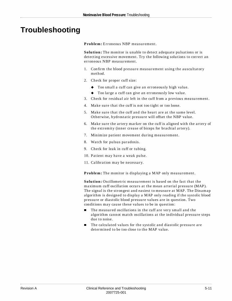
Revision A Clinical Reference and Troubleshooting 5-112007725-001
Noninvasive Blood Pressure: Troubleshooting
Troubleshooting
Problem: Erroneous NBP measurement.
Solution: The monitor is unable to detect adequate pulsations or is detecting excessive movement. Try the following solutions to correct an erroneous NBP measurement.
1. Confirm the blood pressure measurement using the auscultatory method.
2. Check for proper cuff size:
� Too small a cuff can give an erroneously high value.� Too large a cuff can give an erroneously low value.
3. Check for residual air left in the cuff from a previous measurement.
4. Make sure that the cuff is not too tight or too loose.
5. Make sure that the cuff and the heart are at the same level. Otherwise, hydrostatic pressure will offset the NBP value.
6. Make sure the artery marker on the cuff is aligned with the artery of the extremity (inner crease of biceps for brachial artery).
7. Minimize patient movement during measurement.
8. Watch for pulsus paradoxis.
9. Check for leak in cuff or tubing.
10. Patient may have a weak pulse.
11. Calibration may be necessary.
Problem: The monitor is displaying a MAP only measurement.
Solution: Oscillometric measurement is based on the fact that the maximum cuff oscillation occurs at the mean arterial pressure (MAP). The signal is the strongest and easiest to measure at MAP. The Dinamap algorithm is designed to display a MAP only reading if the systolic blood pressure or diastolic blood pressure values are in question. Two conditions may cause these values to be in question:� The measured oscillations in the cuff are very small and the
algorithm cannot match oscillations at the individual pressure steps due to noise.
� The calculated values for the systolic and diastolic pressure are determined to be too close to the MAP value.

5-12 Clinical Reference and Troubleshooting Revision A2007725-001
Noninvasive Blood Pressure: Troubleshooting
The MAP value only is displayed as a safety mechanism when the other values are in question. This MAP only reading is accurate and appropriate for clinical use.
To increase the chance of obtaining a reading for all three blood pressure values, try the following:
1. Check for proper cuff size and placement. (Follow the diagram printed on the cuff.)
2. Minimize patient movement during measurement.
3. The blood pressure cuff should have a bladder width that is 40% of the arm circumference at the greatest diameter of the arm, and a bladder length of 80% of the arm circumference at its greatest point.
4. Wrap the cuff snugly around the limb (tight enough to allow only one finger to fit under the wrapped cuff).
5. Make sure the artery marker on the cuff is aligned with the artery of the extremity (inner crease of biceps for brachial artery).
6. Check for residual air left in the cuff from a previous measurement.
7. In low blood flow states, consider using the auscultative method to verify the reading.
Problem: The MAP reading for calculated MAP does not match the monitor’s MAP.
Solution: The calculation formula assumes that the auscultative method was used to determine the systolic and diastolic pressures. These numbers are used to calculate an approximate MAP. The monitor uses the oscillometric method, where MAP is determined and the systolic and diastolic pressures are then calculated. Only one method of determination should be used, as it is not possible to compare different measurement methods.

Revision A Clinical Reference and Troubleshooting 6-12007725-001
6 SpO2

6-2 Clinical Reference and Troubleshooting Revision A2007725-001
For your notes

Revision A Clinical Reference and Troubleshooting 6-32007725-001
SpO2: Introduction
Introduction
SpO2 monitoring is a noninvasive technique used to measure the amount of oxygenated hemoglobin and pulse rate. This is done by measuring the absorption of selected wavelengths of light. The light generated in the sensor passes through the tissue and is converted into an electrical signal by the photodetector in the sensor. The module or monitor processes the electrical signal and displays a waveform and digital values for SpO2 and pulse rate.
SpO2 Sensor Compatibility
Different modules and monitors use different SpO2 sensors. Not all acquisition modules have an SpO2 connector.� Tram x51 modules are compatible with GE Medical Systems
Information Technologies sensors.� Tram x51M modules are compatible with Masimo LNOP sensors.� Tram x51N modules are compatible with Nellcor Oxismart XL
sensors. Other Nellcor cables cannot be plugged into this connector.� Tram x00 modules with SpO2 are compatible with Ohmeda sensors.� Tram x50 modules are compatible with Nellcor and GE Medical
Systems Information Technologies sensors.� The Solar SpO2 module is compatible with Nellcor and GE Medical
Systems Information Technologies sensors.� The Solar SpO2 module with Masimo SET (referred to as the Masimo
SET module) is compatible with Masimo LNOP sensors.� The Masimo SET configuration on Dash monitors is compatible with
Masimo LNOP sensors.� The Nellcor configuration on Dash monitors is compatible with
Nellcor OxiMax sensors.� The Datex-Ohmeda configuration on Dash monitors is compatible
with Ohmeda and GE Medical Systems Information Technologies sensors.

6-4 Clinical Reference and Troubleshooting Revision A2007725-001
SpO2: Introduction
�����CABLE COMPATIBILITY — Tram 451N and Tram 851N modules require Nellcor Oxismart XL cables and sensors. Older (non-Oxismart XL) cables must not be plugged into the SpO2 connector on these modules. Use of non-Oxismart XL cables may result in erroneous readings.
����The SpO2 cable should plug into the SpO2 connector easily and securely. Do not use excessive force to connect the cable. If the SpO2 cable does not easily fit into the SpO2 connector, it is likely that you do not have the appropriate cable for your SpO2 configuration.
����Nellcor, GE Medical Systems Information Technologies, and Masimo pulse oximetry is calibrated to display functional saturation.
Revision A Clinical Reference and Troubleshooting 6-52007725-001
SpO2: Safety
Safety
Warnings
� A pulse oximeter should NOT be used as an apnea monitor.� A pulse oximeter should be considered an early warning device. As a
trend toward patient deoxygenation is indicated, blood samples should be analyzed by a laboratory co-oximeter to completely understand the patient’s condition.
� Do not use pulse oximeters in the presence of flammable anesthetics or other flammable substances in combination with air, oxygen-enriched environments, or nitrous oxide.
� If the accuracy of any measurement does not seem reasonable, first check the patient’s vital signs, then check for conditions that may cause inaccurate SpO2 readings. If the problem is still not resolved, check the SpO2 module or monitor for proper functioning.����
Refer to “Troubleshooting” on page 6-15 for conditions that may cause inaccurate SpO2 readings.
� The SpO2 module can be used during defibrillation, but the readings may be inaccurate for a short time.
� Do not use SpO2 modules or sensors during magnetic resonance imaging (MRI) scanning. Induced current could potentially cause burns. The module may affect the MRI image, and the MRI unit may affect the accuracy of the oximetry measurements.
� Do not allow tape to block the sensor light detector.� Check that the SpO2 waveform is physiological in shape. (Not
applicable when monitoring SpO2 with Masimo SET technology.)� If the sensor is damaged in any way, discontinue its use immediately.� Prolonged monitoring may require changing the sensor site
periodically. Move the sensor if there is any sign of skin irritation or impaired circulation. Change the sensor site at least every 4 hours to prevent ischemic skin necrosis. Be particularly careful when monitoring neonates. If required, reduce the application periods to half the time recommended above.

6-6 Clinical Reference and Troubleshooting Revision A2007725-001
SpO2: Neonates and Infants
Neonates and Infants
The neonate and infant precautions identified in this section ALWAYS apply when you DO NOT use one the of the following SpO2 acquisition devices: Tram x51 module or Masimo SET module.
�����The display of inaccurate pulse oximetry (SpO2) values has been linked to the presence of poor signal analysis. This condition is most likely to be encountered when the monitor is used on neonates or infants. These same conditions in adults do not impact the SpO2 values to the same extent.
When using pulse oximetry on neonates and infants, always observe the following precautions.
PRECAUTIONS
We recommend the application of the following criteria when using the pulse oximetry function on neonates and infants:
1. The peripheral pulse rate (PPR) as determined by the SpO2 function must be within 10% of the heart rate, and
2. The SpO2 signal strength indicator must have two or three asterisks displayed.
����When monitoring SpO2 using Nellcor Oxismart technology and the Sat-Seconds feature is active, the signal strength asterisks may not be displayed. If they are not displayed, signal strength may be determined by the amplitude of the SpO2 waveform.
Revision A Clinical Reference and Troubleshooting 6-72007725-001
SpO2: Patient Preparation
Patient Preparation
Follow these steps to prepare the patient for SpO2 monitoring.
1. Choose the sensor that is best suited to your patient — ear, finger, disposable, reusable, etc.
����If you are using a Nellcor compatible module, Nellcor’s RS-10 reflective sensor is not recommended for use. Contact Nellcor for other sensor options.
2. Clean the surface of the sensor before and after each use, except when using disposable sensors.
3. Following the instructions provided with the sensor, correctly position and attach the sensor to your patient.
Refer to “Safety” on page 6-5 for general safety precautions when using SpO2 sensors. Be sure to read all literature accompanying sensors for specific safety information.

6-8 Clinical Reference and Troubleshooting Revision A2007725-001
SpO2: Signal and Data Validity
Signal and Data Validity
It is extremely important to determine that the sensor is attached to the patient correctly and that the data is verifiable. To make this determination, three indications from the monitor are of assistance — the signal strength indicator, the quality of the SpO2 waveform, and the stability of the SpO2 values.
Signal Strength Indicator
The signal strength indicator is displayed in the SpO2 parameter window. It consists of 0, 1, 2, or 3 (strongest) asterisks, depending on the strength of the signal. Proper environmental conditions and sensor attachment will help ensure a strong signal.
����When monitoring SpO2 using Nellcor Oxismart technology and the Sat-Seconds feature is active, the signal strength asterisks may not be displayed. If they are not displayed, signal strength may be determined by the amplitude of the SpO2 waveform.
Quality of SpO2 Waveform
����This section is not applicable to monitoring SpO2 with Masimo SET technology.
Under normal conditions, the SpO2 waveform corresponds to (but is not proportional to) the arterial pressure waveform. The typical SpO2 waveform can help the user find a sensor location with the fewest noise spikes. The illustration below represents an SpO2 waveform of good quality.
Good Quality SpO2 Waveform

Revision A Clinical Reference and Troubleshooting 6-92007725-001
SpO2: Signal and Data Validity
If noise (artifact) is seen on the waveform because of poor sensor placement, the photodetector may not be flush with the tissue. Check that the sensor is secured and the tissue sample is not too thick. Pulse rate is determined from the SpO2 waveform, which can be disrupted by hemodynamic pressure disturbances. Motion at the sensor site is indicated by noise spikes in the normal waveform. (See the following figure.)
Stability of SpO2 Waveforms
The stability of the displayed SpO2 values can also be used as an indication of signal validity. Although stability is a relative term, with some practice one can get a good feeling for changes that are artifactual or physiological, and the speed of each.
To aid you in successful SpO2 monitoring, messages are provided in the SpO2 parameter window. Refer to the SpO2 chapter in the appropriate monitor operator’s manual.
�����SIGNAL QUALITY — In the monitoring of patients, the coincidence of adverse conditions may lead to a disturbed signal going unnoticed. In this situation, artifacts are capable of simulating a plausible parameter reading, so that the monitor fails to sound an alarm. In order to ensure reliable patient monitoring, the proper application of the sensor and the signal quality must be checked at regular intervals.
SpO2 Waveform with Artifact

6-10 Clinical Reference and Troubleshooting Revision A2007725-001
SpO2: Masimo SET Technology and Sensors
Masimo SET Technology and Sensors
Acquisition modules and monitors (together referred to as devices) using Masimo SET technology non-invasively measure the amount of oxygenated hemoglobin and pulse rate. The absorption of selected wavelengths of light is measured with Masimo LNOP sensors. Although Masimo SET technology processes the SpO2 measurements differently, the function and appearance of SpO2 on your monitor is essentially the same as SpO2 monitoring with any other SpO2 monitoring device.
No Implied License
Possession or purchase of this device does not convey any express or implied license to use the device with unauthorized replacement parts which would, alone, or in combination with this device, fall within the scope of one or more of the patents relating to this device.
Sensors
Before use, carefully read the Masimo LNOP sensor directions for use.
Use only Masimo oximetry sensors with devices that use Masimo SET technology. Other sensors may cause improper performance.
�� ���SENSOR APPLICATION — Tissue damage can be caused by incorrect application or use of an LNOP sensor, for example by wrapping the sensor too tightly. Inspect the sensor site as directed in the sensor’s directions for use to ensure skin integrity and correct positioning and adhesion of the sensor.
Do not use damaged LNOP sensors. Do not use an LNOP sensor with exposed optical components. Do not immerse the sensor in water, solvents, or cleaning solutions. The sensors are not waterproof. Do not sterilize by irradiation, steam, or ethylene oxide. See the cleaning instructions in the directions for use for reusable Masimo LNOP sensors.

Revision A Clinical Reference and Troubleshooting 6-112007725-001
SpO2: Nellcor Sat-Seconds Alarm Management
Nellcor Sat-Seconds Alarm Management
The Sat-Seconds (or Saturation Seconds) feature available with certain acquisition modules and monitors uses Nellcor technology to decrease the likelihood of false SpO2 alarms caused by motion artifact.
����When monitoring SpO2 using Nellcor technology and the Sat-Seconds feature is active, the signal strength asterisks may not be displayed. If they are not displayed, signal strength may be determined by the amplitude of the SpO2 waveform.
With traditional pulse oximetry alarm management, upper and lower alarm limits are set. During monitoring, as soon as a limit is violated, an alarm is generated.
With Sat-Seconds alarm management, upper and lower alarm limits are set in the same way as traditional alarm management. A Sat-Seconds limit is also set. This allows monitoring of SpO2 saturation outside the set limits for a period of time (count value) before an alarm sounds.
����The Sat-Seconds feature applies to SpO2 saturation only. It does not apply to pulse rate.
The Sat-Seconds feature controls the amount of time that SpO2 saturation may be outside the set limits before an alarm sounds.
����If the Sat-Seconds limit is set to off, any SpO2 limit violation will cause an immediate alarm.
The method of calculation is as follows: The number of percentage points that the SpO2 saturation falls outside the alarm limit is multiplied by the number of seconds that it remains outside the limit. This can be stated as the equation “points x seconds = Sat-Seconds,” where points equals SpO2 percentage points at or outside the limit, and seconds equals the number of seconds SpO2 remains at that point outside the limit.
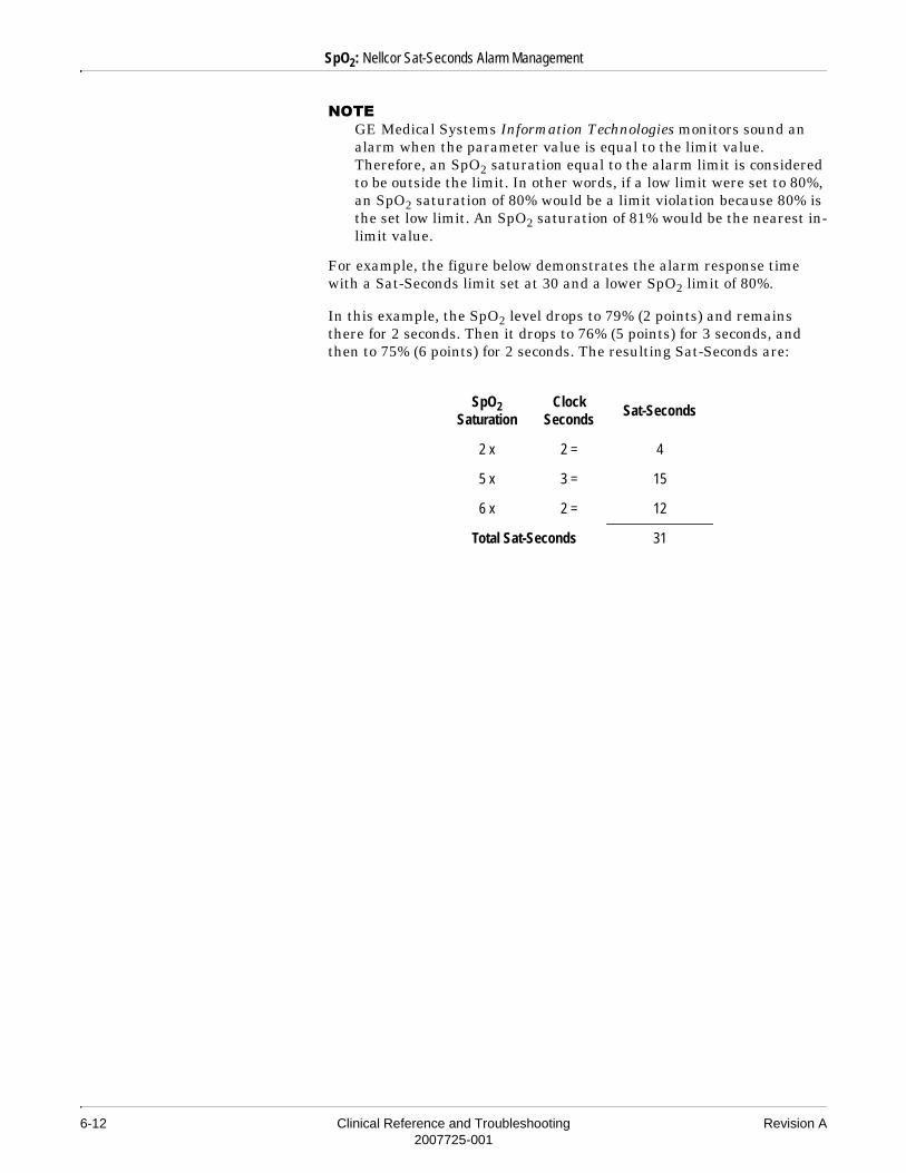
6-12 Clinical Reference and Troubleshooting Revision A2007725-001
SpO2: Nellcor Sat-Seconds Alarm Management
����GE Medical Systems Information Technologies monitors sound an alarm when the parameter value is equal to the limit value. Therefore, an SpO2 saturation equal to the alarm limit is considered to be outside the limit. In other words, if a low limit were set to 80%, an SpO2 saturation of 80% would be a limit violation because 80% is the set low limit. An SpO2 saturation of 81% would be the nearest in-limit value.
For example, the figure below demonstrates the alarm response time with a Sat-Seconds limit set at 30 and a lower SpO2 limit of 80%.
In this example, the SpO2 level drops to 79% (2 points) and remains there for 2 seconds. Then it drops to 76% (5 points) for 3 seconds, and then to 75% (6 points) for 2 seconds. The resulting Sat-Seconds are:
SpO2 Saturation
Clock Seconds
Sat-Seconds
2 x 2 = 4
5 x 3 = 15
6 x 2 = 12
Total Sat-Seconds 31
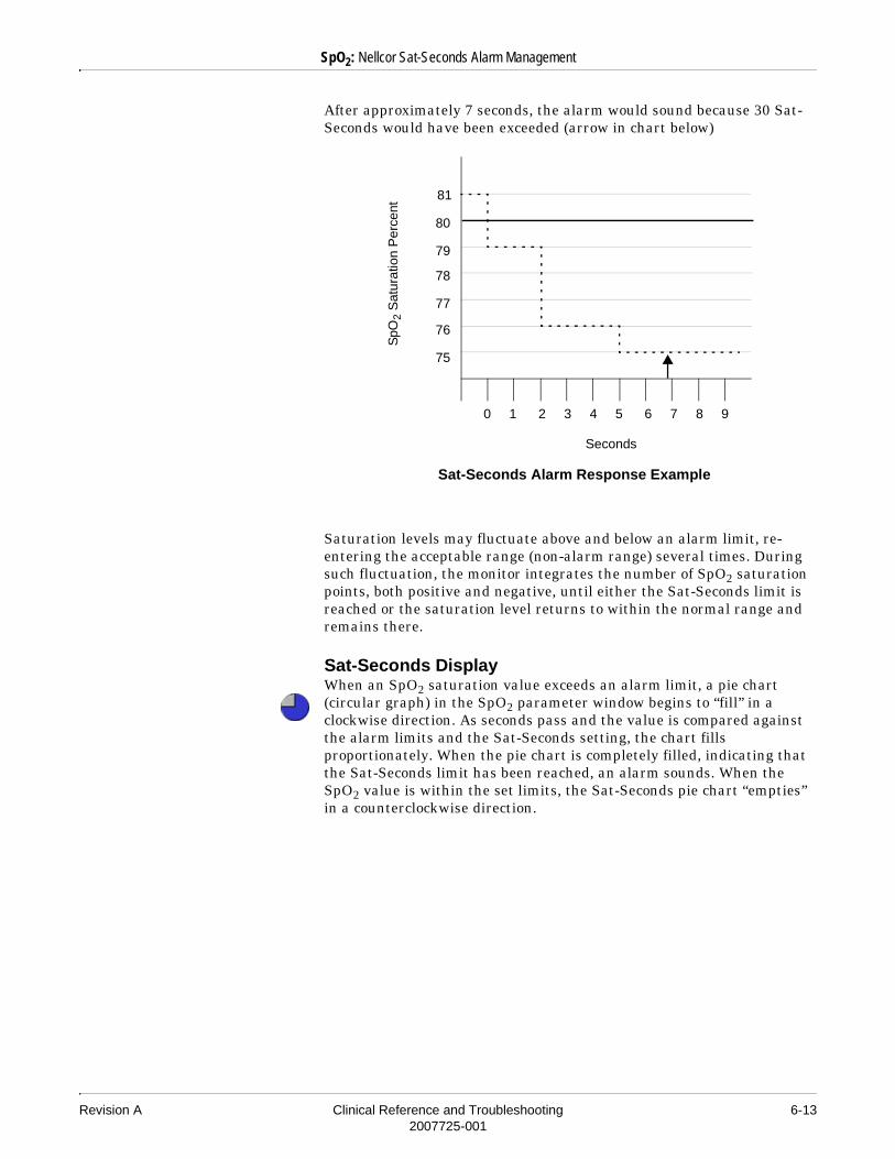
Revision A Clinical Reference and Troubleshooting 6-132007725-001
SpO2: Nellcor Sat-Seconds Alarm Management
After approximately 7 seconds, the alarm would sound because 30 Sat-Seconds would have been exceeded (arrow in chart below)
Saturation levels may fluctuate above and below an alarm limit, re-entering the acceptable range (non-alarm range) several times. During such fluctuation, the monitor integrates the number of SpO2 saturation points, both positive and negative, until either the Sat-Seconds limit is reached or the saturation level returns to within the normal range and remains there.
Sat-Seconds DisplayWhen an SpO2 saturation value exceeds an alarm limit, a pie chart (circular graph) in the SpO2 parameter window begins to “fill” in a clockwise direction. As seconds pass and the value is compared against the alarm limits and the Sat-Seconds setting, the chart fills proportionately. When the pie chart is completely filled, indicating that the Sat-Seconds limit has been reached, an alarm sounds. When the SpO2 value is within the set limits, the Sat-Seconds pie chart “empties” in a counterclockwise direction.
0 1 2 3 4 5 6 7 8 9
SpO
2 S
atur
atio
n P
erce
nt
Seconds
Sat-Seconds Alarm Response Example
81
80
79
78
77
76
75

6-14 Clinical Reference and Troubleshooting Revision A2007725-001
SpO2: Nellcor Sat-Seconds Alarm Management
Sat-Seconds “Safety Net”The Sat-Seconds feature has a “safety net,” designed for patients whose SpO2 saturation is frequently outside the limits but does not remain outside the limits long enough for the Sat-Seconds limit to be reached. When three or more limit violations occur within 60 seconds, an alarm sounds even if the Sat-Seconds limit has not been reached.

Revision A Clinical Reference and Troubleshooting 6-152007725-001
SpO2: Troubleshooting
Troubleshooting
����Refer to “Safety” on page 6-5 for more information about safe pulse oximetry monitoring.
Why does pulse oximetry sometimes read differently than a blood gas analyzer?
Blood gas analyzers calculate the O2 saturation based on normal values for pH, PaCO2, Hb, temperature, etc. (i.e., a normal oxyhemoglobin dissociation curve). Depending on the patient’s physiologic and metabolic status, this curve and all values may be shifted away from “normal.” Thus the oximeter, which measures O2 saturation, may not agree with the blood gas.
How does a pulse oximeter “read” the various types of hemoglobins?
All pulse oximeters utilize two-wavelength absorption. This is because reduced hemoglobin (RHb) and oxyhemoglobin (HbO2) absorb these two wavelengths differently. The hemoglobin saturation is then figured from the measured amounts of the hemoglobins: (SpO2–HbO2)/(HbO2 + RHb).
Carboxyhemoglobin (COHb) absorbs similarly to HbO2 and thus can raise the SpO2. The increase in the SpO2 reading is approximately equal to the amount of COHb present. Normal levels of COHb are 1-2%.
Methemoglobin (MetHb) usually represents less than 1% total Hgb, but in cases such as some IV dyes, antibiotics (such as the sulfas), etc., this level may go up sharply. MetHb absorbs similarly to RHb, and thus could lower the SpO2 reading.

6-16 Clinical Reference and Troubleshooting Revision A2007725-001
SpO2: Troubleshooting
What factors can lead to inaccurate pulse oximetry readings?
Inaccurate SpO2 readings can be caused by any of the following conditions:� Carboxyhemoglobin, methemoglobin, or other dysfunctional
hemoglobins (Refer to the question regarding hemoglobins in this section.)
� Dyes or any substance containing dyes, such as indocyanine green or methylene blue, that change usual arterial pigmentation.
� Dark colored nail polish, especially violets and blues. Removal of nail polish is recommended.
� Long fingernails or artificial fingernails.� Deeply pigmented skin.� Excessive illumination (Refer to the question regarding ambient
light in this section.)� Excessive patient movement (Refer to the question regarding motion
artifact in this section.)� Excessive venous pulsation.� Placement of a sensor on an extremity with a blood pressure cuff,
arterial catheter, or intravascular line.� Patients with anemia can have normal SpO2 readings but low oxygen
content values.� Patients with sickle cell anemia undergoing a sickling crisis may
have erroneous readings because the absorption spectrum of the HbS is different than for normal adult Hb.
� Patients with heavy smoke inhalation can have transiently high CO2 levels and thus a high amount of carboxyhemoglobin and artificially high SpO2. (Refer to the question regarding hemoglobins in this section.)
� Severely jaundiced patients have high levels of bilirubin in their blood. A product of bilirubin metabolism is CO2, and thus high levels of carboxyhemoglobin can be formed. (Refer to the question regarding hemoglobins in this section.)
� Excessive environmental motion or electromagnetic interference may prevent tracking of pulse. Measurements may seem inappropriate or the monitor may not seem to operate correctly.

Revision A Clinical Reference and Troubleshooting 6-172007725-001
SpO2: Troubleshooting
What effect can ambient light have on pulse oximetry monitoring?
Light sources such as surgical lamps, bilirubin lamps, fluorescent lights, infrared heating lamps, and sunlight can cause poor waveform quality and inaccurate readings. Error messages are possible. Shielding the sensor with opaque tape, the posey wrap, or other dark or opaque material can increase oximetry accuracy, verified by good waveform and signal strength.
What does electrosurgical interference look like and how can it be minimized?
Electrosurgical interference is most obvious on the displayed waveform. It is a very spiky, erratic looking waveform caused by the electrosurgical unit’s overwhelming interference. It can result in grossly inaccurate pulse oximeter parameters.
Electrosurgical interference can be minimized by:
1. Making sure the pulse oximeter sensor is as far away from the return pad and operating site as possible.
2. Making sure the sensor is not between the return pad and operating site.
3. Keeping the power cord and sensor cable away from the power cord of the electrosurgical unit.
4. Plugging the electrosurgery unit into a separate set of outlets from the monitor.
What does motion artifact look like, what problems can it cause, and how can it be corrected?
����This question is not applicable to monitoring SpO2 with Masimo SET technology.
Motion artifact occurs with excessive motion of the sensor, the cable leading to the sensor, or the cable/sensor junction. In other words, anything that causes any of these things to move, like the patient moving his hands, or the cable lying across the ventilator tubing and being moved with every cycle, can cause motion artifact. A non-arterial, often erratic looking waveform and a pulse rate that does not coincide with the heart rate on the ECG will result.
The main problem motion artifact can cause is erroneous SpO2 readings.
6-18 Clinical Reference and Troubleshooting Revision A2007725-001
SpO2: Troubleshooting
Motion artifact can be reduced, if not eliminated, by selecting a “quieter” site on the patient. An ear sensor if the hands do not remain still, an adhesive sensor on the toe, or an adhesive sensor on the little finger for an adult or on the sole of the foot in a newborn can help greatly.
Cable movement can be reduced by applying the sensor with the cable leading toward the patient, then taping the cable to the side of the hand or foot. The cable and sensor can also be stabilized with a stress loop near the sensor. Tape the stress loop to the patient. In the case of the butterfly sensor, the tape was designed to secure the cable to the finger.
It has been noted that letting the patient view the SpO2 waveform enables the patient to assist in reducing motion artifact.
Why doesn’t the monitor display an SpO2 reading after changing the Masimo sensor site?
The Masimo sensor is not being recognized by the monitor. Whenever a Masimo sensor is repositioned, you must first disconnect the cable from the sensor. Then reconnect the sensor to the cable after proper patient preparation and placement.
Why isn’t the SpO2 window displayed on the monitor after connecting the SpO2 interface cable and sensor?
No SpO2 data is displayed due to a hardware failure or an unrecognized or defective sensor.
1. Ensure that the sensor is attached to the interface cable and the cable is connected to the acquisition device.
2. Change the sensor.
3. Change the cable.
4. If the problem persists, contact your institution’s biomedical department for service.

Revision A Clinical Reference and Troubleshooting 7-12007725-001
7 Cardiac Output

7-2 Clinical Reference and Troubleshooting Revision A2007725-001
For your notes

Revision A Clinical Reference and Troubleshooting 7-32007725-001
Cardiac Output: Introduction
Introduction
The cardiac output (CO) program measures cardiac output by use of a thermodilution catheter. A numeric value and, during measurement, a real-time cardiac output washout curve are displayed on the monitor. The program allows for multiple determination trials. Those determined to be invalid by the user can be discarded, while up to four valid measurements are automatically averaged by the program. When saved, the averaged value is entered into calculations and trends.
����On some acquisition modules, the CO connector can be used for both temperature monitoring and cardiac output measurements, but not simultaneously. If using the connector on these modules for cardiac output, you can purchase a separate temperature module to do temperature monitoring simultaneously with cardiac output.
Cardiac Output Washout Curve
The washout curve, which appears on the monitor display after a CO injection, shows the drop in blood temperature as the injectate mixes with the blood. The peak of the curve indicates the maximum difference in the patient’s baseline blood temperature and the temperature of the injectate solution. As the mixture passes through the catheter and then out the pulmonary artery, the temperature difference decreases as indicated by the curve returning to the baseline. A spike is displayed at the onset of the curve, again at 70% of the maximum temperature difference, and again at 35% of the maximum temperature difference. This curve is captured at reduced size in the trial chart.
Onset spike
70% spike
35% spike
Cardiac Washout Curve

7-4 Clinical Reference and Troubleshooting Revision A2007725-001
Cardiac Output: Bath Probe Setup
Bath Probe Setup
Balloon
Thermistor Connector
Proximal Injectate Port Balloon Inflation
ValveDistal Lumen
Injectate Probe Connector
Bath Probe
Distal Lumen Hub
Thermistor
Syringe for Injection
Check Valve
To pressure monitoring tubing
Proximal Injectate Hub
Cooling Canister and Coil (Optional)
695B
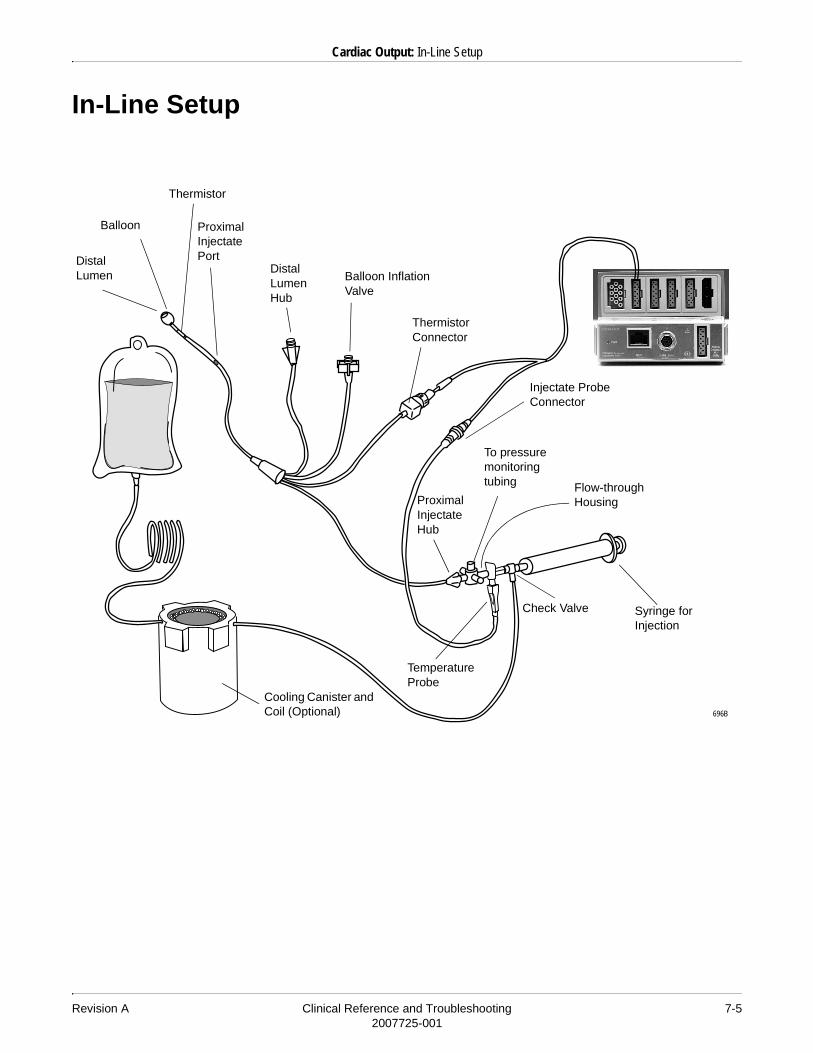
Revision A Clinical Reference and Troubleshooting 7-52007725-001
Cardiac Output: In-Line Setup
In-Line Setup
Balloon
Thermistor Connector
Proximal Injectate Port
Balloon Inflation Valve
Distal Lumen
Injectate Probe Connector
Distal Lumen Hub
Thermistor
Flow-through Housing
Check Valve
To pressure monitoring tubing
Proximal Injectate Hub
Cooling Canister and Coil (Optional)
Syringe for Injection
Temperature Probe
696B

7-6 Clinical Reference and Troubleshooting Revision A2007725-001
Cardiac Output: Cardiac Calculations
Cardiac Calculations
Refer to “Cardiac Calculations” on page 7-6 for information about monitored and calculated cardiac calculation parameters.
Refer to your monitor operator’s manual for instructions about using the cardiac calculations program.

Revision A Clinical Reference and Troubleshooting 7-72007725-001
Cardiac Output: Troubleshooting
Troubleshooting
Problem: Inaccurate cardiac output values.
Solutions:
1. Technique — It is important to understand the technique used in performing a cardiac output since it is a major influencing factor in obtaining accurate cardiac output values.
a. If room temperature solution is used, be sure the bag is not exposed to a supplemental heat source or touching other solutions or equipment. This is important so the solution temperature will be the same as the room air temperature sensed through the bath or in-line probe. Any difference in temperature could give an inaccurate reading.
b. When injecting, always hold the syringe by the plunger and not by the barrel. The temperature of the solution increases at a slower rate if the barrel is not held, and therefore reduces the potential for error in a cardiac output value.
����When in-line is being used along with iced injectate, the initial temperature displayed will be the room temperature. However, when the solution is injected, the temperature displayed will decrease.
c. It is recommended that you inject rapidly and smoothly into the proximal port of the Swan-Ganz catheter, usually within 4 to 5 seconds.
d. Allow at least 1 to 1.5 minutes between injections to allow the baseline to stabilize.
e. It is also recommended that you inject at the patient’s end expiration. This helps reduce any respiratory noise and therefore lessens error.
f. A minimum difference of 10° C between the patient blood temperature (BT) and solution/injectate temperature (IT) is recommended.

7-8 Clinical Reference and Troubleshooting Revision A2007725-001
Cardiac Output: Troubleshooting
2. Respiration — The patient’s inspiratory/expiratory cycle and placement of the catheter affects the cardiac output value. Whenever the patient inhales and exhales, the temperature in the lung changes. During inspiration, the patient’s blood temperature decreases and during expiration it increases. Therefore, placement of the catheter in relation to proximity of the lung fields affects the baseline.
If there is a significant amount of respiratory noise on the patient’s baseline, the monitor may try to calculate a cardiac output even if no injection was performed. This is because the monitor does not differentiate between temperature change caused by breaths versus injections. It simply looks for a change in baseline temperature.
3. Baseline blood temperature — As little as a half a degree Celsius change in blood temperature due to respiratory noise may cause a CO value to be displayed when an injection has not been performed. Using auto mode allows the monitor to look for a stable baseline before allowing an injection.
4. Swan-Ganz catheter — The catheter itself may be damaged (e.g., defective thermistor or defective tubing).
5. Hemodynamics — The patient’s rhythm can affect the cardiac output value. If cardiac output trials are being done at a time when the patient has arrhythmias, you may notice a discrepancy in the cardiac output values.
6. Rapid IV solutions — Any rapid IV solution that is infusing at the time when the solution is injected can alter the cardiac output value. Maintain a constant rate, or if possible, stop the solution 30 seconds before the CO injection and then restart the infusion after the cardiac output is calculated.
7. IT (injectate temperature) fluctuation — If the IT is fluctuating, check the IT cable connection.
Problem: Cardiac output value lower than expected
Solution:
1. Decrease the volume injected.
2. Increase the temperature of the injectate.
����Cardiac output must be computed within 20 seconds. Decreasing the volume and increasing the temperature will give you a smaller differential change and should increase the chance of computing a cardiac output within the 20-second period.

Revision A Clinical Reference and Troubleshooting 7-92007725-001
Cardiac Output: Troubleshooting
Problem: Cardiac output value higher than expected
Solution:
1. Increase the volume injected.
2. Decrease the temperature of the injectate.
����Cardiac output must be computed within 20 seconds. Increasing the volume and decreasing the temperature will give you a greater differential change.
Problem: The monitor cannot detect a stable baseline temperature. A message is displayed on the monitor. (The message clears if a stable baseline temperature is found.)
Solution:
1. Check the patient and the CO setup (both the monitor settings and the cables.)
2. Check for a significant amount of respiratory variation and for rapid IV solution infusion, either of which may influence the baseline temperature. It may be necessary to stop or slow the solution infusion during CO measurement, however, use caution if the solution includes drugs/medication.
3. Check the injectate temperature (IT). There should be a minimum temperature difference of 10° C between the patient blood temperature and the injectate solution temperature. Cool the injectate solution if needed to increase the difference.
4. Replace the injectate temperature cable.
5. The Swan-Ganz catheter may be damaged.
Problem: The monitor is calculating cardiac output even though solution has not been injected.
Solution: The monitor is sensing a change in the patient’s blood temperature consistent with an injection.
1. Check the patient and the CO setup (both the monitor settings and the cables.)
2. Check for a significant amount of respiratory variation and for rapid IV solution infusion, either of which may influence the baseline temperature. It may be necessary to use the manual cardiac mode rather than the automatic mode.

7-10 Clinical Reference and Troubleshooting Revision A2007725-001
Cardiac Output: Troubleshooting
For your notes

Revision A Clinical Reference and Troubleshooting 8-12007725-001
8 Respiration

8-2 Clinical Reference and Troubleshooting Revision A2007725-001
For your notes

Revision A Clinical Reference and Troubleshooting 8-32007725-001
Respiration: General Information
General Information
�����NO BREATH/APNEA EVENTS — The monitor may not detect all episodes of inadequate breathing, nor does it distinguish between central, obstructive, and mixed apnea events.
�����ELECTRODE CONFIGURATION — Impedance respiration monitoring is not reliable when ECG electrodes are placed on the limbs.
����Respiration monitoring is not adversely affected by the use of an ESU ECG filter.
When monitoring CO2, a respiration rate is always displayed in the CO2 parameter window. The respiration rate measurement from CO2 should be the preferred measurement method, as an impedance respiration rate can be disrupted by many conditions.
Respiration rate is detected by measuring thoracic impedance changes through ECG lead I or lead II.� Lead I provides good thoracic (upper chest) breath detection. � Lead II provides good thoracic breath detection and upper abdominal
(lower chest) breath detection.

8-4 Clinical Reference and Troubleshooting Revision A2007725-001
Respiration: General Information
����The following illustrations are used to show the relationship between breathing and ECG lead. They do NOT represent an electrode configuration.
If you are monitoring with a fixed-lead, 3-lead cable, respiration can only be obtained from the lead for which the cable is manufactured. For example, if the cable is a fixed lead II cable, as indicated by a label on the cable itself, respiration can only be obtained from lead II.
Even though the same electrodes are used for ECG and respiration monitoring, it is possible to get a lead fail message for respiration without one for ECG. The impedance may be too high for respiration detection, but the electrode is still good for ECG. If needed, replace the leads or the electrode for respiration.
ECG Lead I for Upper Chest Breather
ECG Lead II for Chest or Upper Abdominal Breather
Revision A Clinical Reference and Troubleshooting 8-52007725-001
Respiration: General Information
Since respiration monitoring is so closely linked with ECG monitoring, patient preparation and electrode placement are important. Refer to the ECG chapter in this manual, as well as your monitor operator’s manual, for guidelines.
Monitoring Respiration on Pacemaker Patients
�� ���FDA POSTMARKET SAFETY ALERT — The United States FDA Center for Devices and Radiological Health issued a safety bulletin October 14, 1998. This bulletin states “that minute ventilation rate-adaptive implantable pacemakers can occasionally interact with certain cardiac monitoring and diagnostic equipment, causing the pacemakers to pace at their maximum programmed rate.”
The FDA further recommends precautions to take into consideration for patients with these types of pacemakers. These precautions include disabling the rate responsive mode and enabling an alternate pace mode. For more information contact:
Office of Surveillance and Biometrics, CDRH, FDA1350 Piccard Drive, Mail Stop HFZ-510Rockville, MD 20850U.S.A.
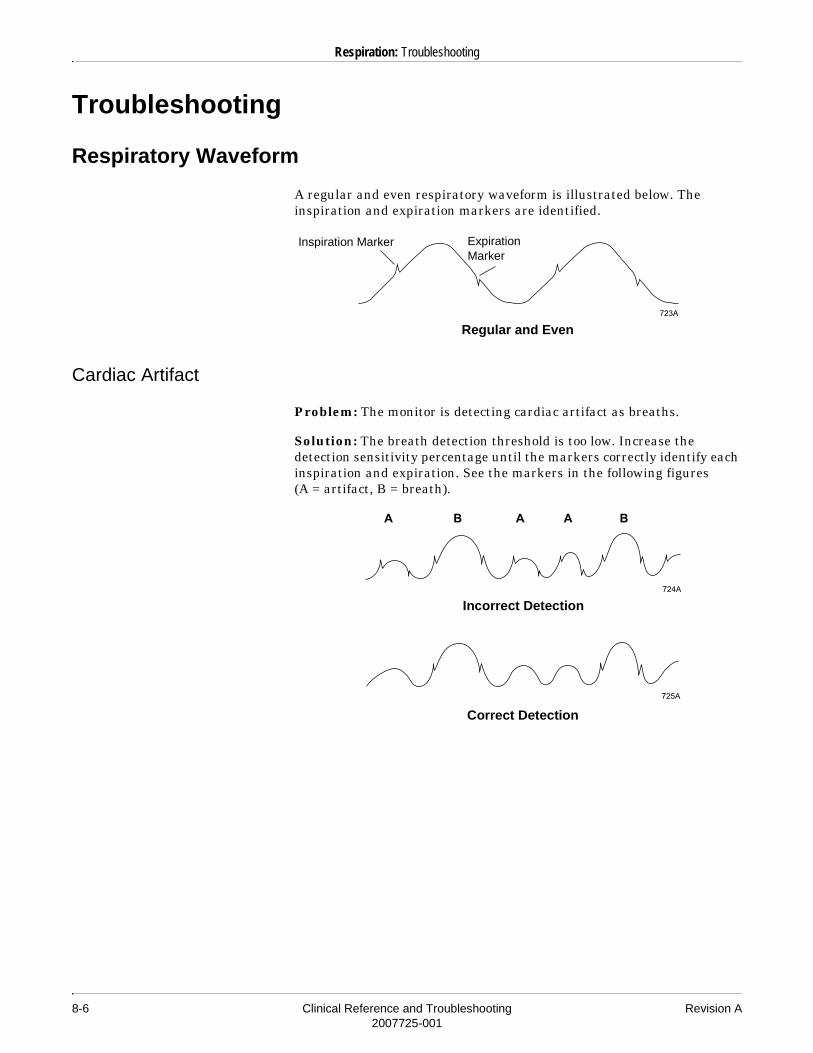
8-6 Clinical Reference and Troubleshooting Revision A2007725-001
Respiration: Troubleshooting
Troubleshooting
Respiratory Waveform
A regular and even respiratory waveform is illustrated below. The inspiration and expiration markers are identified.
Cardiac Artifact
Problem: The monitor is detecting cardiac artifact as breaths.
Solution: The breath detection threshold is too low. Increase the detection sensitivity percentage until the markers correctly identify each inspiration and expiration. See the markers in the following figures (A = artifact, B = breath).
Inspiration Marker Expiration Marker
Regular and Even
Incorrect Detection
Correct Detection

Revision A Clinical Reference and Troubleshooting 8-72007725-001
Respiration: Troubleshooting
Varying Waveform Amplitudes
Problem: The waveform has a combination of shallow and deep breaths, and the monitor is not detecting the shallow breaths.
Solution: The detection sensitivity threshold is set too high and the shallow breaths are not being detected. Decrease the detection sensitivity percentage until the markers correctly identify each inspiration and expiration. See the markers in the following figures (B = breath).
Incorrect Detection
Correct Detection

8-8 Clinical Reference and Troubleshooting Revision A2007725-001
Respiration: Troubleshooting
For your notes

Revision A Clinical Reference and Troubleshooting 9-12007725-001
9 Respiratory Mechanics

9-2 Clinical Reference and Troubleshooting Revision A2007725-001
For your notes

Revision A Clinical Reference and Troubleshooting 9-32007725-001
Respiratory Mechanics: Introduction
Introduction
The Respiratory Mechanics (RM-M) module provides continuous noninvasive monitoring of inspired and expired flow, volume and airway pressures, and respiration rate on adult, pediatric, and neonatal patients.
Respiratory Mechanics Parameters
The derived pulmonary calculation values are figured automatically. The chart below shows the derived pulmonary calculations, the labels used to identify these on the monitor, the units of measure, and the formulas used.
Derived Pulmonary Calculations
Parameter Label Unit Formula
Minute Volume MV l/min V/t
Minute Volume Spontaneous MVs l/min Vs/ts
Minute Volume Mechanical MVm l/min Vm/tm
Tidal Volume TV ml MV/RR
Tidal Volume Spontaneous TVs ml MVs/RRs
Tidal Volume Mechanical TVm ml MVm/RRm
Peak Expiratory Flow PEF l/min Max (Exp. Flow)
Resistance Expiratory RAWe cm H2O/L/sec
Work of Breathing WOBm J/L
Mean Airway Pressure MAWP cm H2O
Peak Inspiratory Pressure PIP cm H2O Max (Insp. Pressure)
Positive End Expiratory Pressure
PEEP cm H2O After 50% of PEF, average (exp. pressure) for 40 ms if pressure does not vary by more than ±0.1 cm H2OElse lowest exp. pressure
RΣV
2 ΣPV ΣPV ΣVV–
ΣV2 ΣV
2 ΣVV( )2–
----------------------------------------------------------=
Σinspiration Pi PEEP–( ) *Vi
Σbreath Pi( ) / # samples

9-4 Clinical Reference and Troubleshooting Revision A2007725-001
Respiratory Mechanics: Introduction
Intrinsic PEEP PEEPi cm H2O Pressure at flow reversal if pressure ≥ PEEP
Respiratory Rate RR breaths/min 60/t
Respiratory Rate Spontaneous RRs breaths/min 60/ts
Respiratory Rate Mechanical RRm breaths/min 60/tm
Dynamic Compliance CDYN ml/cm H2O
I:E Time Ratio I:E Inspired time/Expired time
Derived Pulmonary Calculations
Parameter Label Unit Formula
CΣV
2
ΣPV RΣVV–-----------------------------------=

Revision A Clinical Reference and Troubleshooting 9-52007725-001
Respiratory Mechanics: Patient Connection
Patient Connection
�� ���FLOW SENSOR — The flow sensor is intended to be in the patient circuit only when the RM-M module is powered on. Prolonged exposure with the module powered off may degrade performance. The flow sensor and associated tubing in the patient circuit could be subjected to elevated concentrations of oxygen or anesthetic agents.
The connection between the RM-M module and the patient should be set up according to the following:
Patient Connection to the RM-M Module

9-6 Clinical Reference and Troubleshooting Revision A2007725-001
Respiratory Mechanics: Patient Connection
�� ���DISPOSABLES — Flow sensors are disposable devices and therefore are intended for single patient use. They should not be reused as performance could degrade or contamination could occur.
�� ���FAULTY CONNECTIONS — Faulty connections may cause inaccurate readings and/or leakage of anesthetic agents, which could contaminate room air.
The proper tube has a thin line on it. The line should be positioned proximal to the patient.
Arrow should point upward.
Flow Sensor

Revision A Clinical Reference and Troubleshooting 9-72007725-001
Respiratory Mechanics: Patient Connection
The illustration below shows a combined flow sensor with a CO2 sensor attached. This is an optional configuration.
To CO2 module
To RM-M module
CO2 sensor
Combined flow sensor
Combined Flow Sensor with CO2 Sensor Attached (Optional Configuration)

9-8 Clinical Reference and Troubleshooting Revision A2007725-001
Respiratory Mechanics: RM Waveforms
RM Waveforms
After the RM parameter window is displayed on the monitor, you can display three RM waveforms:� Flow� Pressure� Volume
Two types of loops are also available for display:� Flow-volume� Pressure-volume
Sample RM Waveforms
An example of each waveform and loop is shown below.
Flow Waveform
Pressure Waveform
Volume Waveform
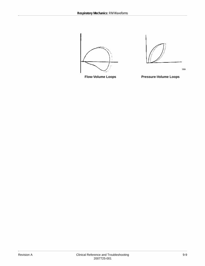
Revision A Clinical Reference and Troubleshooting 9-92007725-001
Respiratory Mechanics: RM Waveforms
Flow-Volume Loops Pressure-Volume Loops
508A

9-10 Clinical Reference and Troubleshooting Revision A2007725-001
Respiratory Mechanics: RM Waveforms
For your notes

Revision A Clinical Reference and Troubleshooting 10-12007725-001
10 SvO2

10-2 Clinical Reference and Troubleshooting Revision A2007725-001
For your notes
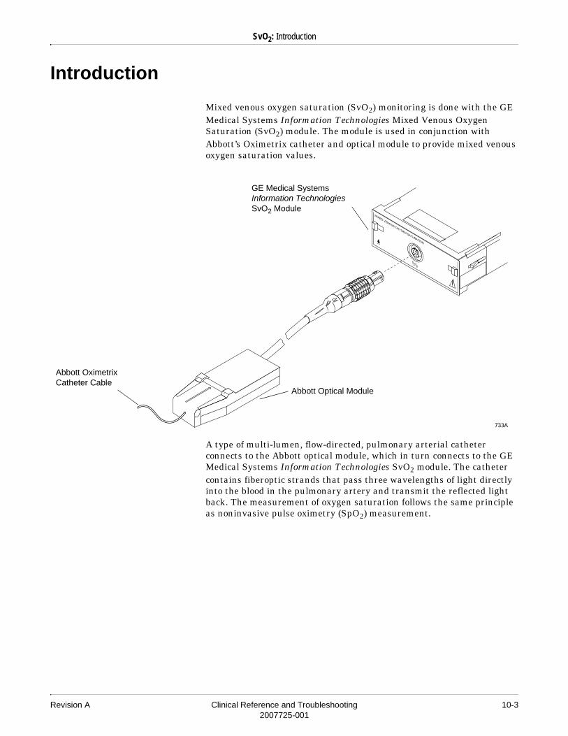
Revision A Clinical Reference and Troubleshooting 10-32007725-001
SvO2: Introduction
Introduction
Mixed venous oxygen saturation (SvO2) monitoring is done with the GE Medical Systems Information Technologies Mixed Venous Oxygen Saturation (SvO2) module. The module is used in conjunction with Abbott’s Oximetrix catheter and optical module to provide mixed venous oxygen saturation values.
A type of multi-lumen, flow-directed, pulmonary arterial catheter connects to the Abbott optical module, which in turn connects to the GE Medical Systems Information Technologies SvO2 module. The catheter contains fiberoptic strands that pass three wavelengths of light directly into the blood in the pulmonary artery and transmit the reflected light back. The measurement of oxygen saturation follows the same principle as noninvasive pulse oximetry (SpO2) measurement.
GE Medical Systems Information Technologies SvO2 Module
Abbott Oximetrix Catheter Cable
Abbott Optical Module

10-4 Clinical Reference and Troubleshooting Revision A2007725-001
SvO2: Introduction
SvO2 measures the percentage of hemoglobin carrying oxygen in the venous blood. When blood passes through the lungs, oxygen combines with hemoglobin molecules, resulting in a saturation of approximately 100% in a healthy person. When the blood passes through the tissues, a fraction of the hemoglobin molecules release their oxygen to meet the metabolic needs of the cells. The normal percentage of hemoglobin retaining oxygen in venous blood is 60-80%. This value varies with cardiac output, oxygen consumption of the tissues, and the amount of normally functioning hemoglobin.

Revision A Clinical Reference and Troubleshooting 10-52007725-001
SvO2: Signal Strength Indicator
Signal Strength Indicator
It is important to determine that the signal coming from the Abbott catheter is adequate for reliable saturation readings. To make this determination, the monitor displays a signal strength indicator.
The signal strength indicator may be displayed in the SvO2 parameter window and next to each calibration event in the SvO2 calibration history. This indicator consists of one, two, or three asterisks, or three dashes. The clinical implications of this indicator are as follows:� Three asterisks condition — Optimum light intensity.� Two asterisks condition — Adequate light intensity for a reliable
saturation value.� One asterisk condition — Inadequate light intensity for a reliable
saturation value. A saturation value is displayed under these conditions, but it may not be reliable. The clinician should exercise caution and rectify the light intensity problem as soon as possible.
� Three dashes — Inadequate light for any calculation. No saturation values are displayed.

10-6 Clinical Reference and Troubleshooting Revision A2007725-001
SvO2: Troubleshooting
Troubleshooting
Problem: A preinsertion calibration failure message is displayed on the monitor.
Solution:
The preinsertion calibration was unsuccessful.
1. Check the connections between the optical module and the SvO2 module.
2. Check the connections between the optical module and the catheter.
3. Verify that the tip of the catheter is in the optical reference block.
4. Check the optical module.*
5. Replace the catheter.
* See below for the optical module test procedure.
Problem: A low light or no light message is displayed on the monitor.
Solution:
If the catheter is out of the package but not in the patient, this message is normal.
If the catheter is in the package, follow these troubleshooting steps.
1. Check the connections between the optical module and the SvO2 module.
2. Check the connections between the optical module and the catheter.
3. Verify that the tip of the catheter is in the optical reference block.
4. Check the optical module.*
* See below for the optical module test procedure.
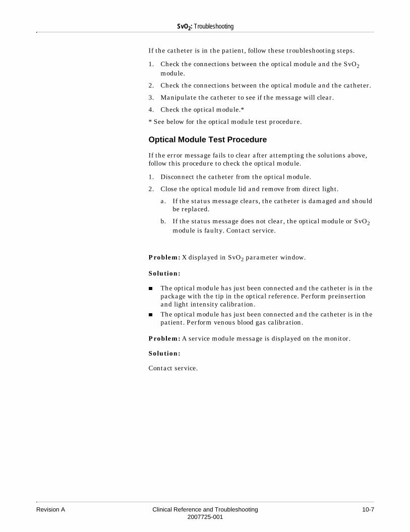
Revision A Clinical Reference and Troubleshooting 10-72007725-001
SvO2: Troubleshooting
If the catheter is in the patient, follow these troubleshooting steps.
1. Check the connections between the optical module and the SvO2 module.
2. Check the connections between the optical module and the catheter.
3. Manipulate the catheter to see if the message will clear.
4. Check the optical module.*
* See below for the optical module test procedure.
Optical Module Test Procedure
If the error message fails to clear after attempting the solutions above, follow this procedure to check the optical module.
1. Disconnect the catheter from the optical module.
2. Close the optical module lid and remove from direct light.
a. If the status message clears, the catheter is damaged and should be replaced.
b. If the status message does not clear, the optical module or SvO2 module is faulty. Contact service.
Problem: X displayed in SvO2 parameter window.
Solution:
� The optical module has just been connected and the catheter is in the package with the tip in the optical reference. Perform preinsertion and light intensity calibration.
� The optical module has just been connected and the catheter is in the patient. Perform venous blood gas calibration.
Problem: A service module message is displayed on the monitor.
Solution:
Contact service.

10-8 Clinical Reference and Troubleshooting Revision A2007725-001
SvO2: Troubleshooting
For your notes

Revision A Clinical Reference and Troubleshooting 11-12007725-001
11 End-Tidal CO2

11-2 Clinical Reference and Troubleshooting Revision A2007725-001
For your notes

Revision A Clinical Reference and Troubleshooting 11-32007725-001
End-Tidal CO2: Introduction
Introduction
End-tidal CO2 monitoring (referred to as CO2 monitoring) is a continuous, noninvasive technique for determining the concentration of CO2 (carbon dioxide) in respiratory gas by measuring the absorption of infrared light of specific wavelengths.
The light generated in the analyzer bench is passed through respiratory gas. The amount of absorption by CO2 is measured and digitized by the photodetector. The module processes the electronic signal and displays a waveform and digital values for expired CO2, inspired CO2, and respiratory rate.
Depending on the device and setup used, patients can be monitored whether intubated or non-intubated.
End-tidal CO2 monitoring is done with a variety of GE Medical Systems Information Technologies’ CO2 devices:
� Capnostat Mainstream CO2 module — for intubated patients
� Capnostat Dual CO2 module — for either intubated or non-intubated patients
� Sidestream CO2 module — for either intubated or non-intubated patients
� Dash 3000/4000 monitor — for intubated patients� Dash 3000/4000 monitor with CapnoFlex LF CO2 module — for
either intubated or non-intubated patients

11-4 Clinical Reference and Troubleshooting Revision A2007725-001
End-Tidal CO2: Safety
Safety
Cautions
� CO2 SOURCE — Do not attempt to use a combination of gas monitoring modules (e.g., end-tidal CO2 module and SAM) at the same time. Only data from one acquisition source is displayed.
� DEVICE PROXIMITY — Capnostat and CapnoFlex CO2 monitoring devices should not be used in close proximity to wireless networking equipment, or in the presence of strong electromagnetic fields such as those generated by radio station transmitters, citizens band radios, cellular phones, etc. Using a Capnostat or CapnoFlex sensor under the above conditions may cause one or all of the following to occur:� Artifact (noise) may be induced on the capnogram.� The CO2 parameter values may be replaced by X.
� A check adapter or calibrate sample line message may be displayed in the parameter window.
Normal operation will resume when the source of interference is removed.
Capnostat sensors with a serial number less than 26104 require a separation distance of 8.2 feet (2.5 m) and are not recommended for use on monitoring equipment equipped with the Wireless LAN option.
� GAS EXHAUST LINE — Do not allow the gas exhaust line to become kinked or blocked. Back pressure may cause inaccurate gas readings and also may cause serious damage to the module’s internal components.
� INFECTIOUS DISEASE — To avoid the spread of infectious disease, do not allow the exhaust to discharge in the direction of the patient or the user.
� LEAK DETECTION — The sidestream analyzer will not detect a leak in the breathing circuit. A leak in the breathing circuit may cause inaccurate readings.

Revision A Clinical Reference and Troubleshooting 11-52007725-001
End-Tidal CO2: Safety
� SIDESTREAM SAMPLE RATES — The Capnostat dual CO2 module withdrawal rate is 180 milliliters per minute (nominal).The Sidestream CO2 module continuously withdraws 200 milliliters per minute from the patient airway.
The CapnoFlex LF CO2 module withdrawal rate is 50 milliliters per minute.
Do not use these modules on any patient who may be adversely affected by their withdrawal rates (e.g., a neonate with low tidal volume).
� VACUUM SOURCE — Do NOT connect the exhaust to an unregulated high vacuum source. Pressure may cause inaccurate gas readings and also may cause serious damage to the equipment’s internal components.
� WIRELESS LAN INTERFERENCE — To minimize potential interference, Capnostat sensors with a serial number of 26104 or greater require a separation distance of 10 inches (25 cm) from the Wireless LAN adapter.

11-6 Clinical Reference and Troubleshooting Revision A2007725-001
End-Tidal CO2: Setup
Setup
Capnostat Mainstream Setup
1. Connect the sensor to the module or monitor. Zero the sensor if a message indicating you should calibrate the sensor to the zero cell appears in the CO2 parameter window. Refer to the monitor operator’s manual for calibration information.
2. Confirm that the monitor’s barometric pressure setting is correct. Refer to the appropriate service manual for information on how to set the barometric pressure.
3. Position the adapter and sensor in the patient respiratory circuit as close to the patient as possible. A location between the endotracheal tube and the ventilator circuit is common.
�����FLUID CONCENTRATIONS — Always position the sensor with the adapter in an upright position to avoid collection of fluids on the windows of the adapter. Large concentrations of fluids at this point will obstruct gas analysis.
097A
Sensor cable
Reference and Zero cells
Capnostat sensor (upright position)
Capnostat airway adapter
To patient endotracheal tube
Mainstream Setup

Revision A Clinical Reference and Troubleshooting 11-72007725-001
End-Tidal CO2: Setup
Capnostat Sidestream Setup (Dual CO2 Module)
An Aqua-Knot water trap must be used with the Capnostat dual module sidestream setup and with the sidestream CO2 module setup. It is not needed for the CapnoFlex LF CO2 module. The Aqua-Knot water trap holds 7 cc of water.
The arrow on the Aqua-Knot water trap shows the direction of the gas flow. When inserting the water trap, the arrow should point toward the module.
�� ���WATER TRAP — An Aqua-Knot water trap must always be used when the unit is running. Failure to use the water trap can result in contamination of the internal gas measurement instruments and may cause subsequent inaccurate gas analysis.
Replace and dispose of the Aqua-Knot water trap when occluded. Do not reuse if occluded. Reusing an occluded water trap may cause inaccurate readings and may damage the equipment.
����Routine replacement of the Aqua-Knot water trap is not required.
�� ���CONTAMINATION — To prevent contamination of the internal gas measurement instruments, be sure the pump is off before removing the Aqua-Knot water trap.
����Delivery of bronchodilators and/or mucolytics via aerosol and meter dose inhalers can be corrosive and cause premature blockage of the Aqua-Knot water trap. Discontinue sidestream gas analysis prior to treatment by switching the pump off and removing the sample line from the breathing circuit.
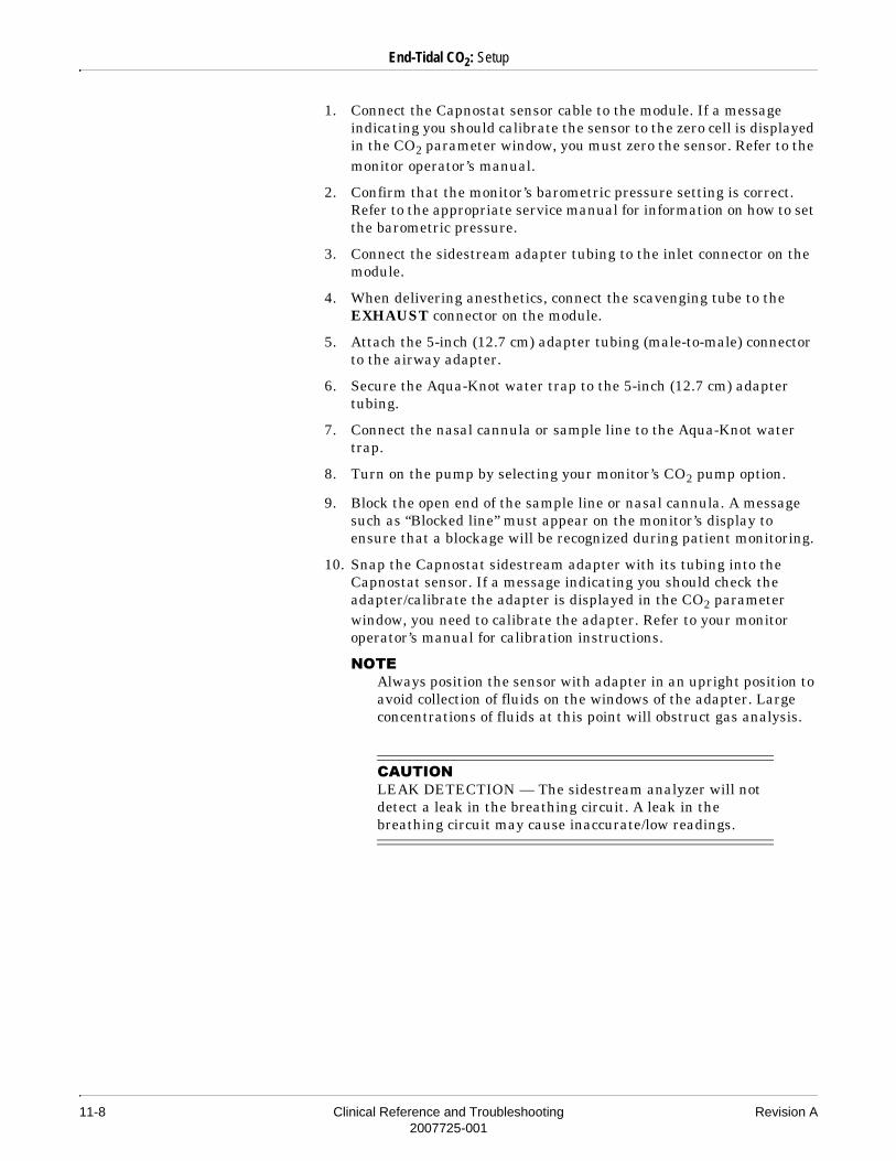
11-8 Clinical Reference and Troubleshooting Revision A2007725-001
End-Tidal CO2: Setup
1. Connect the Capnostat sensor cable to the module. If a message indicating you should calibrate the sensor to the zero cell is displayed in the CO2 parameter window, you must zero the sensor. Refer to the monitor operator’s manual.
2. Confirm that the monitor’s barometric pressure setting is correct. Refer to the appropriate service manual for information on how to set the barometric pressure.
3. Connect the sidestream adapter tubing to the inlet connector on the module.
4. When delivering anesthetics, connect the scavenging tube to the EXHAUST connector on the module.
5. Attach the 5-inch (12.7 cm) adapter tubing (male-to-male) connector to the airway adapter.
6. Secure the Aqua-Knot water trap to the 5-inch (12.7 cm) adapter tubing.
7. Connect the nasal cannula or sample line to the Aqua-Knot water trap.
8. Turn on the pump by selecting your monitor’s CO2 pump option.
9. Block the open end of the sample line or nasal cannula. A message such as “Blocked line” must appear on the monitor’s display to ensure that a blockage will be recognized during patient monitoring.
10. Snap the Capnostat sidestream adapter with its tubing into the Capnostat sensor. If a message indicating you should check the adapter/calibrate the adapter is displayed in the CO2 parameter window, you need to calibrate the adapter. Refer to your monitor operator’s manual for calibration instructions.
����Always position the sensor with adapter in an upright position to avoid collection of fluids on the windows of the adapter. Large concentrations of fluids at this point will obstruct gas analysis.
�� ���LEAK DETECTION — The sidestream analyzer will not detect a leak in the breathing circuit. A leak in the breathing circuit may cause inaccurate/low readings.

Revision A Clinical Reference and Troubleshooting 11-92007725-001
End-Tidal CO2: Setup
11. Position the nasal cannula on the patient according to the manufacturer’s instructions or attach the patient sample line to the patient airway adapter.

11-10 Clinical Reference and Troubleshooting Revision A2007725-001
End-Tidal CO2: Setup
Sidestream Setup for Non-Intubated Patients
Capnostat Dual CO2 module
Sidestream adapter tubing (30.5 cm)
Scavenging tube
Sensor cable
Reference and Zero cells
Capnostat sensor (upright position)
Sidestream airway adapter
12.7 cm adapter tubing
Aqua-Knot II *
Nasal cannula *
* Disposable component
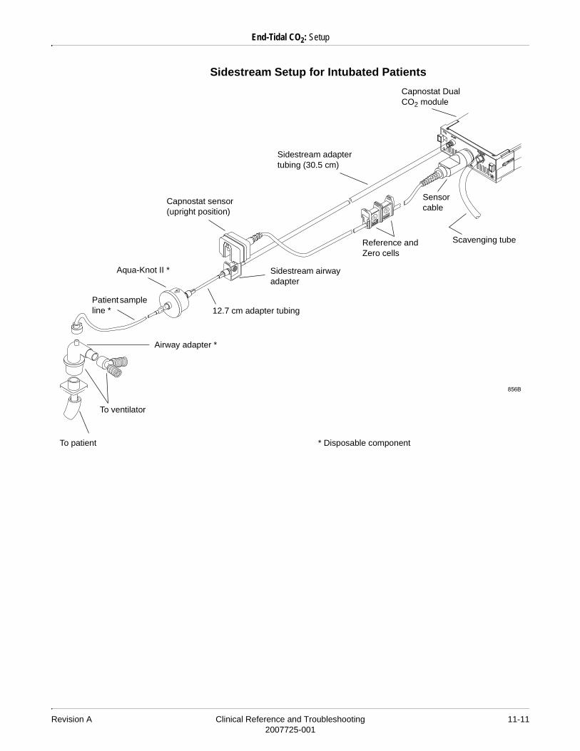
Revision A Clinical Reference and Troubleshooting 11-112007725-001
End-Tidal CO2: Setup
Sidestream Setup for Intubated Patients
Capnostat Dual CO2 module
Sidestream adapter tubing (30.5 cm)
Scavenging tube
Sensor cable
Reference and Zero cells
Capnostat sensor (upright position)
Sidestream airway adapter
12.7 cm adapter tubing
Aqua-Knot II *
Patient sample line *
* Disposable component
To ventilator
To patient
Airway adapter *

11-12 Clinical Reference and Troubleshooting Revision A2007725-001
End-Tidal CO2: Setup
Gas Exhaust
The gas exhaust may be scavenged using the scavenging adapter package (pn 9504-016). Follow the steps below to properly connect the module to an anesthesia machine exhaust circuit.
1. Remove the exhaust adapter and tube from the package.
2. Attach the connector end of the exhaust tube to the outlet marked EXHAUST on the module.
3. Install the exhaust adapter into the gas scavenging system of the anesthesia delivery system, following the anesthesia machine manufacturer’s recommended procedure.
4. Drape the exhaust tube so that it does not interfere with the work area.
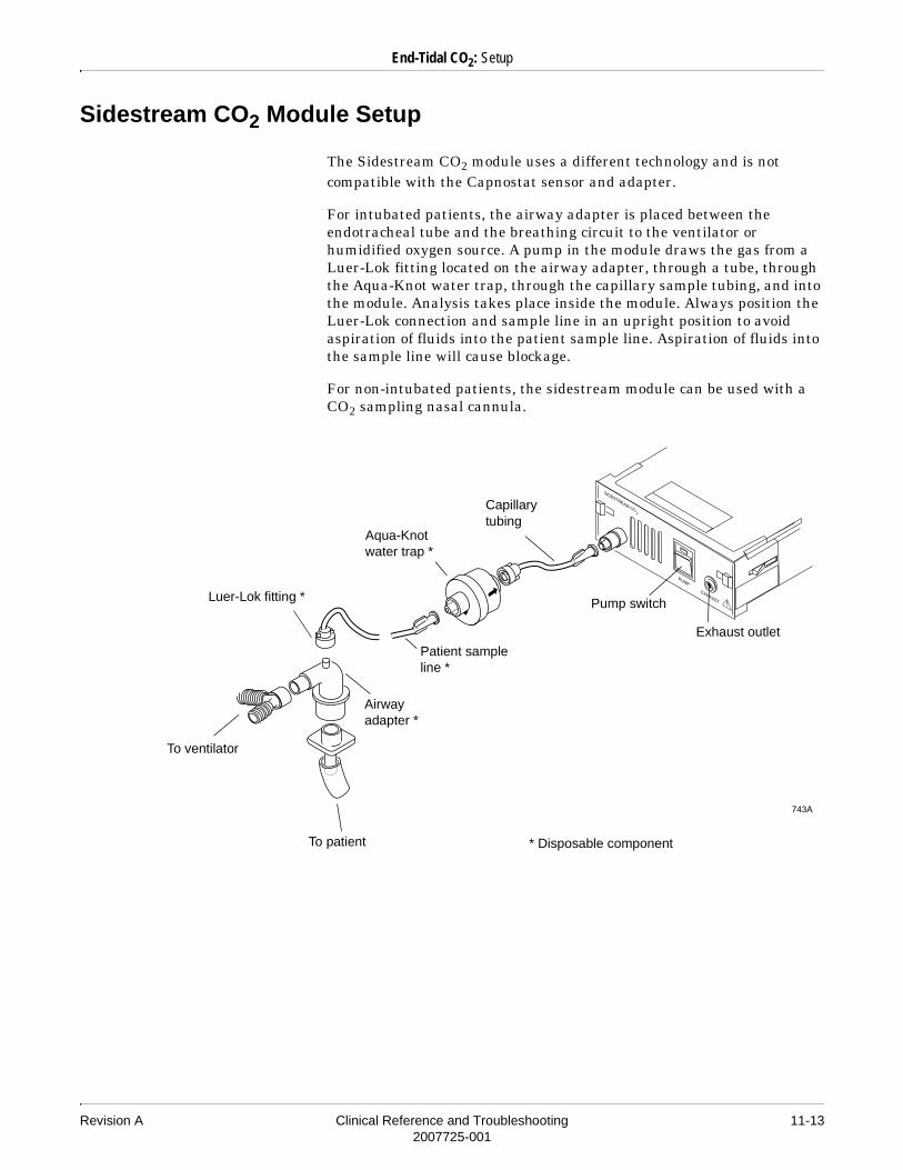
Revision A Clinical Reference and Troubleshooting 11-132007725-001
End-Tidal CO2: Setup
Sidestream CO2 Module Setup
The Sidestream CO2 module uses a different technology and is not compatible with the Capnostat sensor and adapter.
For intubated patients, the airway adapter is placed between the endotracheal tube and the breathing circuit to the ventilator or humidified oxygen source. A pump in the module draws the gas from a Luer-Lok fitting located on the airway adapter, through a tube, through the Aqua-Knot water trap, through the capillary sample tubing, and into the module. Analysis takes place inside the module. Always position the Luer-Lok connection and sample line in an upright position to avoid aspiration of fluids into the patient sample line. Aspiration of fluids into the sample line will cause blockage.
For non-intubated patients, the sidestream module can be used with a CO2 sampling nasal cannula.
Luer-Lok fitting *
Aqua-Knot water trap *
Capillary tubing
Pump switch
Exhaust outlet
Patient sample line *
Airway adapter *
* Disposable component
To ventilator
To patient

11-14 Clinical Reference and Troubleshooting Revision A2007725-001
End-Tidal CO2: Setup
CapnoFlex LF Sidestream CO2 Module Setup
1. Connect the module to the CO2 connector on the patient monitor. A message indicating the module is warming up appears on the monitor.
2. If a message indicating that the sample line should be calibrated appears on the monitor, refer to your monitor operator’s manual for calibration instructions.
3. Connect the sample line to the module and to the patient.
Scavenger portSample line connector
CO2 Connection

Revision A Clinical Reference and Troubleshooting 11-152007725-001
End-Tidal CO2: Troubleshooting
Troubleshooting
Capnostat Sensor Check
The sensor cable has two cells, as shown in the figure below. One is marked “-0-” (zero), and one is marked “REF” (reference). Whenever you suspect incorrect values or sensor failure, perform a sensor check.
Follow these steps to perform a sensor check.
1. Remove the adapter from the sensor, but be sure that the sensor cable is still connected to the module or monitor.
2. Ensure that the cell windows are clean and dry.
Capnostat sensor
This end must be connected to the module/monitor.
-0- cell
REF cell

11-16 Clinical Reference and Troubleshooting Revision A2007725-001
End-Tidal CO2: Troubleshooting
3. Place the sensor on the cell marked “REF.” Depending on the units of measure, you should see a reading of 38 mmHg (± 2 mmHg) on the monitor. If the displayed value is within range, you can resume monitoring. If the sensor is not within range, a message indicating that it is not calibrated appears. You must calibrate the sensor to the zero cell. Refer to your monitor operator’s manual for calibration instructions.
�����CO2 VALUES — The end-tidal CO2 value (ETCO2) is, in most cases, considerably lower than the CO2 partial pressure determined by blood-gas analysis.
The major clinical reasons are dead-space ventilation, ventilation/perfusion mismatch, a drop in cardiac output, alveolar shunts, and incomplete emptying of the alveoli.
TECHNICAL REASONS (MUST BE CORRECTED):
Leak in the respiratory circuit; hypothermia, but blood-gas analysis not corrected to a lower temperature; and anesthesia gases (correction possible for O2 and N2O only).
Literature
Bhavani-Shankar, K. et al: Capnometry and anaesthesia (Review Article). Can. J. Anaesth. 39, 617-632 (1992)
Raemer, D.B. et al: Variation in pCO2 between Arterial Blood and Peak Expired Gas during Anaesthesia. Anesth. Analg. 62, 1065-1069 (1983)

Revision A Clinical Reference and Troubleshooting 12-12007725-001
12 Anesthetic Agent Analysis

12-2 Clinical Reference and Troubleshooting Revision A2007725-001
For your notes

Revision A Clinical Reference and Troubleshooting 12-32007725-001
Anesthetic Agent Analysis: Introduction
Introduction
GE Medical Systems Information Technologies Smart Anesthesia Multi-gas (SAM) module is an infrared based, multi-gas analyzer that measures respiratory rate and inspired and expired values for respiratory gases.
Following is a list of gases the module measures:� O2
� CO2
� N2O
� Enflurane� Halothane� Isoflurane� Desflurane� Sevoflurane
Two Models
There are two models of the SAM module, one with an O2 sensor and one without. The module without the O2 sensor is labeled in two ways. On the top of the module, the product name reads SAM 80. In addition, a label reading No O2 Sensor is on the front panel. Operating instructions are similar for both modules. Please ignore any references to O2 if you have the SAM 80 module.
12-4 Clinical Reference and Troubleshooting Revision A2007725-001
Anesthetic Agent Analysis: Safety
Safety
Cautions
� AGENT EXPOSURE — Connect exhaust port to a scavenging system to prevent exposure to waste anesthetic agents.
� ANESTHETIC AGENT VERIFICATION — When administering anesthetic agents, always verify your anesthetic vaporizer settings.
� AQUA-KNOT WATER TRAP — An Aqua-Knot water trap must always be used when the unit is running. Failure to use the water trap can result in contamination of the internal gas measurement components and may cause inaccurate gas analysis. Replace and dispose of the Aqua-Knot water trap when occluded. Do not reuse. Reusing the water trap may cause inaccurate readings and may damage the equipment.
� ETHANOL AND METHANE — The presence of ethanol or methane with halogenated agents can interfere with and cause inaccuracy in the agent values. Methane, even when no halogenated agent is present, will cause a value to be displayed.
� MULTIPLE GAS MODULES — Do not attempt to use a combination of gas monitoring modules/systems (e.g., CO2 with SAM) at the same time. Only data from the first acquisition source to detect CO2 or gases will be displayed.If a configured patient monitor has end-tidal CO2 monitoring capability, the SAM module will always take precedence as the source for end-tidal CO2 measurement when connected.
� SAMPLE RATE — The SAM module continuously withdraws about 250 milliliters per minute (nominal) from the patient airway. The SAM 80 module has a withdrawal rate of about 150 milliliters per minute. Do not use the module on any patient who may be adversely affected by this sampling rate (e.g., a neonate with low tidal volume).

Revision A Clinical Reference and Troubleshooting 12-52007725-001
Anesthetic Agent Analysis: Safety
Notes
� Delivery of bronchodilators or mucolytics via aerosol and meter dose inhalers can be corrosive and cause premature blockage of the Aqua-Knot water trap. Discontinue gas analysis prior to treatment by removing the sample line from the breathing circuit.
� For intubated patients, always position the Luer-Lok connection and patient sample line in an upright position to avoid aspiration of fluids into the patient sample line, which will cause premature blockage of the Aqua-Knot water trap.

12-6 Clinical Reference and Troubleshooting Revision A2007725-001
Anesthetic Agent Analysis: Connections
Connections
�� ���SAMPLE LINE — PE/PVC type patient sample line must be used with the SAM module.
The PE/PVC sample line should have an inner diameter of 1.19 mm (0.047 inches). Other size sample lines may cause inaccurate readings.
����The arrow on the Aqua-Knot water trap shows the direction of the gas flow. When inserting the Aqua-Knot water trap, the arrow should point toward the module.
004C
AQUA-KNOT
PUMP
COMMEXHAUST
Smart Anesthesia Multi-gas Module
SAM module
Aqua-Knot water trap *
Patient sample line
Luer-Lok fitting *
Airway adapter *
Endotracheal tubeExhaust line to scavenging system
* Disposable component
To ventilator
To patient

Revision A Clinical Reference and Troubleshooting 12-72007725-001
Anesthetic Agent Analysis: Connections
1. Insert the Aqua-Knot water trap into the front end of the SAM module and turn it clockwise until secure. Do NOT overtighten.
2. Secure the patient sample line (PE/PVC) to the Aqua-Knot water trap (Luer-Lok fitting).
3. Secure the other end of the patient sample line to the airway adapter with a Luer-Lok fitting in an UPWARD position.
����For non-intubated patients, a sampling nasal cannula can be used, replacing the patient sample line. The Aqua-Knot water trap must still be used.
Gas Exhaust
Waste gas may be scrubbed and returned to the patient breathing circuit or scavenged using the scavenging adapter package (pn 9504-016) included with each SAM module. Follow the steps below to properly connect the module to an anesthesia machine’s exhaust system.
1. Remove the exhaust adapter and line from the package.
2. Attach the connector end of the exhaust line to the outlet marked EXHAUST on the front of the module.
3. Install the exhaust adapter into a gas scavenging system.
4. Drape the exhaust line so that it does not obstruct the work area.
�� ���EXHAUST LINE — Do not allow the exhaust line to become kinked or blocked.
Back pressure may cause inaccurate gas readings and also may cause serious damage to the module’s internal components.
�� ���VACUUM SOURCE — Do NOT connect the exhaust of the SAM module to an unregulated high vacuum source. Pressure may cause inaccurate gas readings and also may cause serious damage to the module’s internal components.
12-8 Clinical Reference and Troubleshooting Revision A2007725-001
Anesthetic Agent Analysis: Room Air Calibration
Room Air Calibration
The SAM module is designed to periodically calibrate to room air. Room air calibration takes about 8 seconds. During room air calibration, the host monitor displays a message indicating that air calibration is in progress. The last measured parameter values are still displayed, but the CO2 waveform drops to the baseline.
The SAM module can be stored inserted in the Rac. If not inserted, there will be a “warming up” period once inserted back into the Rac. If the SAM temperature is >60 degrees F (16 degrees C), the warm-up time is 30 seconds. If the temperature is < 60 degrees F (16 degrees C), the warm-up time is 20 minutes.

Revision A Clinical Reference and Troubleshooting 13-12007725-001
13 Transcutaneous pO2/pCO2

13-2 Clinical Reference and Troubleshooting Revision A2007725-001
For your notes
Revision A Clinical Reference and Troubleshooting 13-32007725-001
Transcutaneous pO2/pCO2: Introduction
Introduction
The Transcutaneous (TC) module acquires transcutaneous oxygen and/or carbon dioxide partial pressure measurements diffused through patient skin. It is designed for the continuous, noninvasive trend monitoring of oxygen and/or carbon dioxide. It is indicated for use as a monitor of skin surface pCO2 and/or pO2 in neonates NOT under anesthesia. The unit displays trends over time and may be used as an adjunct or supplement for arterial pCO2 and/or pO2 measurements in those patients requiring frequent blood gas analyses.
����This equipment is not a blood gas measurement device.

13-4 Clinical Reference and Troubleshooting Revision A2007725-001
Transcutaneous pO2/pCO2: Safety
Safety
Warnings
� DEFIBRILLATION — The TC module is NOT defibrillator proof. Disconnect the sensor and sensor cable from the patient prior to defibrillation.
� SURGICAL DEVICES — This device is not intended for use with high frequency surgical devices.
Cautions
� HUMIDITY — Operating the device outside of the specified humidity range may reduce data accuracy. Avoid moving the equipment from a cold environment to a warm, humid environment. Allow the device to stabilize to the new temperature before operating.
� MOISTURE — Do not operate the device if any component is damp or wet from condensation or spills. This poses a risk of burns, and physiological data may not be available.

Revision A Clinical Reference and Troubleshooting 13-52007725-001
Transcutaneous pO2/pCO2: Measurement Requirements
Measurement Requirements
The measurement requirements described in this section ensure accurate data and patient safety.
Recommended Sites
The best sites for measuring TCpO2 and TCpCO2 include areas with:
� High capillary density and blood flow.� Thin epidermis.� Not prone to effects of shunting.
����The best measurement sites for neonates are the abdomen and the chest.
����Avoid using measuring sites located over bony prominences.

13-6 Clinical Reference and Troubleshooting Revision A2007725-001
Transcutaneous pO2/pCO2: Measurement Requirements
Recommended Temperatures
�����BLISTER HAZARD — Long-term hyperthermia may blister the skin. When producing local hyperaemia by means of hyperthermia, a certain risk of applying temperatures harmful to the skin is always present, although limited, due to the control system of the module.
However, for special patients (e.g., in shock, with low blood pressure, neonates, and patients with vascular constrictions) particular care should be taken whenever hyperthermia is applied.
Check sensor sites frequently to assess patient tolerance to hyperthermia.
�� ���BURN HAZARD — To prevent the risk of skin burns or blisters, use the lowest sensor temperature providing TCpO2 and TCpCO2 trending values.
For neonates, the recommended sensor temperature is from 42°C to 44°C.
For adults, the recommended sensor temperature is from 43°C to 45°C.
�� ���Do not allow the electrode temperature to exceed 43°C for neonates and 44°C for adults when electrodes are attached to the skin for more than four hours.
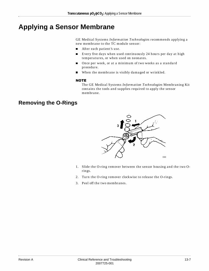
Revision A Clinical Reference and Troubleshooting 13-72007725-001
Transcutaneous pO2/pCO2: Applying a Sensor Membrane
Applying a Sensor Membrane
GE Medical Systems Information Technologies recommends applying a new membrane to the TC module sensor:� After each patient’s use.� Every five days when used continuously 24 hours per day at high
temperatures, or when used on neonates.� Once per week, or at a minimum of two weeks as a standard
procedure. � When the membrane is visibly damaged or wrinkled.
����The GE Medical Systems Information Technologies Membraning Kit contains the tools and supplies required to apply the sensor membrane.
Removing the O-Rings
1. Slide the O-ring remover between the sensor housing and the two O-rings.
2. Turn the O-ring remover clockwise to release the O-rings.
3. Peel off the two membranes.
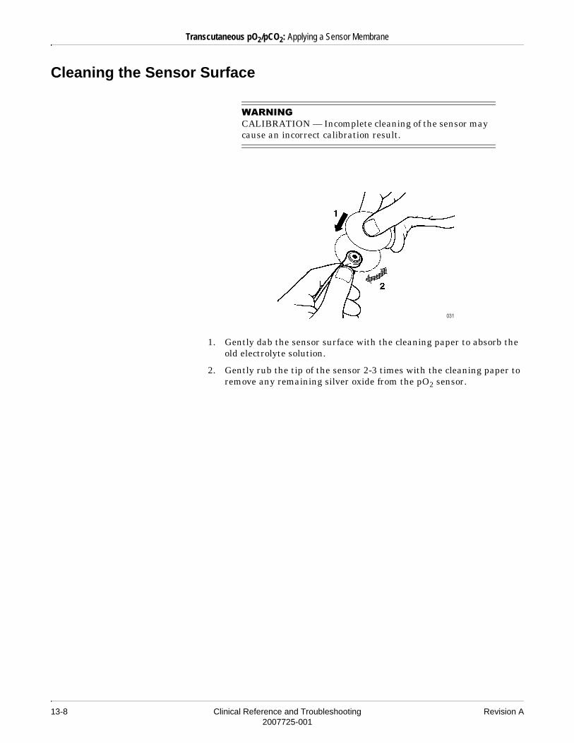
13-8 Clinical Reference and Troubleshooting Revision A2007725-001
Transcutaneous pO2/pCO2: Applying a Sensor Membrane
Cleaning the Sensor Surface
�����CALIBRATION — Incomplete cleaning of the sensor may cause an incorrect calibration result.
1. Gently dab the sensor surface with the cleaning paper to absorb the old electrolyte solution.
2. Gently rub the tip of the sensor 2-3 times with the cleaning paper to remove any remaining silver oxide from the pO2 sensor.
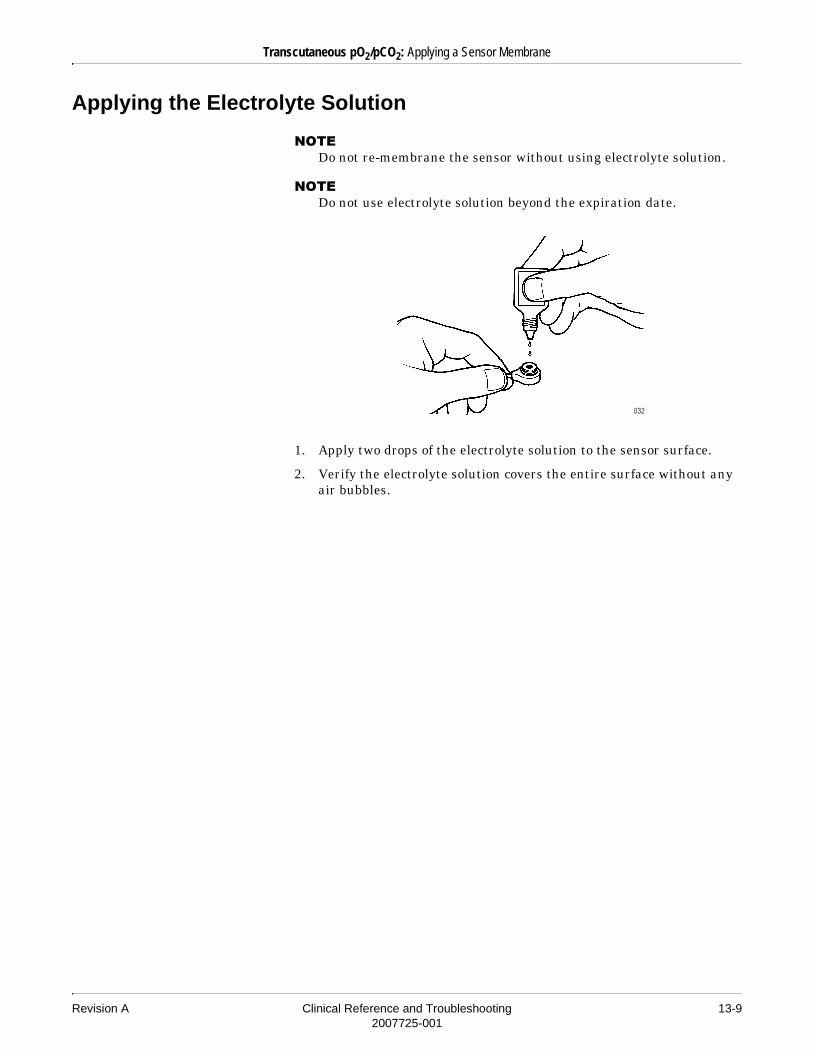
Revision A Clinical Reference and Troubleshooting 13-92007725-001
Transcutaneous pO2/pCO2: Applying a Sensor Membrane
Applying the Electrolyte Solution
����Do not re-membrane the sensor without using electrolyte solution.
����Do not use electrolyte solution beyond the expiration date.
1. Apply two drops of the electrolyte solution to the sensor surface.
2. Verify the electrolyte solution covers the entire surface without any air bubbles.

13-10 Clinical Reference and Troubleshooting Revision A2007725-001
Transcutaneous pO2/pCO2: Applying a Sensor Membrane
Applying the New Membrane
1. Insert and press the sensor head into the TC module membrane unit until you hear a clicking sound.
2. Remove the sensor.
3. Wipe off the excess electrolyte solution with a soft tissue.

Revision A Clinical Reference and Troubleshooting 13-112007725-001
Transcutaneous pO2/pCO2: Applying the Sensor
Applying the Sensor
�����DATA ACCURACY — The anesthetic halothane may interfere with TCpO2 monitoring. The effect of typical concentrations of halothane and nitrous oxide on TCpO2 readings is approximately 10%.
The TC module is not intended to monitor skin surface pO2 in neonates under anesthesia.
Halothane does not affect TCpCO2 monitoring.
�� ���DATA ACCURACY — TCpO2 and TCpCO2 monitoring is not recommended on patients in a compromised hemodynamic state.
����You can start the standby mode during monitoring by placing the sensor into the sensor socket. The sensor heater will shut down if the sensor is in the sensor socket for more than 30 minutes. This will minimize drying out of the electrolyte. Recalibrate the sensor if it remains in the sensor socket for a total of 2.5 hours or more.
No alarms will occur while the sensor is in standby mode.
����The GE Medical Systems Information Technologies Fixation Kit contains the supplies required to apply the sensor to the patient.

13-12 Clinical Reference and Troubleshooting Revision A2007725-001
Transcutaneous pO2/pCO2: Applying the Sensor
Applying the Fixation Ring
1. Remove the film from the fixation ring’s adhesive disk.
2. Use your finger to gently press the center of the fixation ring onto the measuring site.
3. Firmly run your finger around the rim of the adhesive disk to prevent leaks.
Adding the Contact Fluid
Fill the center of the fixation ring with 4–5 drops of contact fluid.
1 2 3
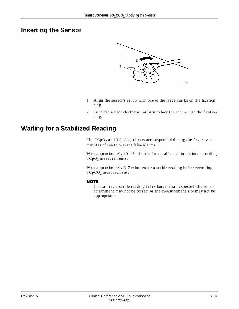
Revision A Clinical Reference and Troubleshooting 13-132007725-001
Transcutaneous pO2/pCO2: Applying the Sensor
Inserting the Sensor
1. Align the sensor’s arrow with one of the large marks on the fixation ring.
2. Turn the sensor clockwise 1/4 turn to lock the sensor into the fixation ring.
Waiting for a Stabilized Reading
The TCpO2 and TCpCO2 alarms are suspended during the first seven minutes of use to prevent false alarms.
Wait approximately 10–15 minutes for a stable reading before recording TCpO2 measurements.
Wait approximately 3–7 minutes for a stable reading before recording TCpCO2 measurements.
����If obtaining a stable reading takes longer than expected, the sensor attachment may not be correct or the measurement site may not be appropriate.
2
1
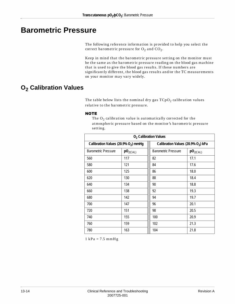
13-14 Clinical Reference and Troubleshooting Revision A2007725-001
Transcutaneous pO2/pCO2: Barometric Pressure
Barometric Pressure
The following reference information is provided to help you select the correct barometric pressure for O2 and CO2.
Keep in mind that the barometric pressure setting on the monitor must be the same as the barometric pressure reading on the blood gas machine that is used to give the blood gas results. If these numbers are significantly different, the blood gas results and/or the TC measurements on your monitor may vary widely.
O2 Calibration Values
The table below lists the nominal dry gas TCpO2 calibration values relative to the barometric pressure.
����The O2 calibration value is automatically corrected for the atmospheric pressure based on the monitor’s barometric pressure setting.
1 kPa = 7.5 mmHg
O2 Calibration Values
Calibration Values (20.9% O2) mmHg Calibration Values (20.9% O2) kPa
Barometric Pressure pO2(CAL) Barometric Pressure pO2(CAL)
560 117 82 17.1
580 121 84 17.6
600 125 86 18.0
620 130 88 18.4
640 134 90 18.8
660 138 92 19.3
680 142 94 19.7
700 147 96 20.1
720 151 98 20.5
740 155 100 20.9
760 159 102 21.3
780 163 104 21.8

Revision A Clinical Reference and Troubleshooting 13-152007725-001
Transcutaneous pO2/pCO2: Barometric Pressure
CO2 Calibration Values
The table below lists the nominal dry gas TCpCO2 calibration values relative to the barometric pressure.
����The CO2 calibration value is automatically corrected for the atmospheric pressure based on the monitor’s barometric pressure setting.
1 kPa = 7.5 mmHg
CO2 Calibration Values
mmHg kPa
Barometric Pressure 5% CO2 Barometric Pressure 5% CO2
560 28 82 4.1
580 29 84 4.2
600 30 86 4.3
620 31 88 4.4
640 32 90 4.5
660 33 92 4.6
680 34 94 4.7
700 35 96 4.8
720 36 98 4.9
740 37 100 5.0
760 38 102 5.1
780 39 104 5.2

13-16 Clinical Reference and Troubleshooting Revision A2007725-001
Transcutaneous pO2/pCO2: Correction for the Effects of Heat Applied to the Skin
Correction for the Effects of Heat Applied to the Skin
The externally applied heat used in transcutaneous monitoring causes a significant increase in blood flow to the skin beneath the sensor. This increase in blood flow leads to a shorter transmit time in the capillaries, thus a tissue pCO2 equilibration closer to the pCO2 of the incoming arterial blood. However, as the external heat also causes a rise in the temperature of the tissue, the TCpCO2 reading will be higher than the pCO2 if measured with the same blood flow at 37°C. The metabolic CO2 production in the living epidermal tissue further increases the TCpCO2 reading.
The following formula corrects the TCpCO2 reading on the TC module for both the temperature effect and the epidermal metabolic contribution.
In the formula above:� TCpCO2 = Nominal pCO2 value
� PsCO2(37°C) = TCpCO2 value reading corrected to 37°C (assuming a patient temperature of 37°C)
� T = Actual electrode temperature in °C� 0.021 = Anaerobic temperature coefficient of pCO2 in blood1
� k = metabolism correction factor (0.0 to –8.0 mmHg or 0.0 to –1.0 kPa)
1 ref. “The Acid Base Status of Blood” by Ole Siggaard-Andersen. Munksgaard, Copenhagen 1976, p. 89.
To correct the TCpCO2 reading on the TC module, use the host monitor’s Severinghaus or in Vivo Correction options. Refer to the appropriate monitor operator’s manual.
PsCO2 37°C( ) TCpCO2 100.021 T-37( )–
k–=

Revision A Clinical Reference and Troubleshooting 13-172007725-001
Transcutaneous pO2/pCO2: Sensor Troubleshooting
Sensor Troubleshooting
Reduction in O2 and CO2 Sensitivity
pO2 Values
Use this procedure to check the sensor’s electrode zero current.
1. Remove the calibrated sensor from the sensor socket.
2. Pour fresh Zero Solution into a small beaker.
3. Immerse the sensor’s surface into the solution for 60 seconds.
����Always use fresh Zero Solution, only immerse the sensor’s surface, and never leave the sensor in contact with the solution for more than 60 seconds.
4. Read the TCpO2 value displayed on the patient monitor screen.
� If the TCpO2 value is less than 5 mmHg (0.7 kPa), the sensor is in good working condition.
� If the TCpO2 value is greater than 5 mmHg (0.7 kPa), you must re-membrane and re-calibrate the sensor.
5. Rinse the sensor thoroughly with distilled water.

13-18 Clinical Reference and Troubleshooting Revision A2007725-001
Transcutaneous pO2/pCO2: Sensor Troubleshooting
pCO2 Values
����The reduction of the sensor’s CO2 sensitivity may be caused by residual electrolyte solution not removed during the membraning procedure. Clean the sensor as described in “Cleaning the Sensor Surface” on page 13-8. Then complete the steps below.
Use this procedure to check the sensor’s sensitivity to CO2.
1. Calibrate the sensor to 38 mmHg (5.1 kPa) using the standard calibration gas mixture.
2. Replace the standard calibration gas with the CAL2 gas cylinder (10% CO2).
3. Read the pCO2 value displayed on the patient monitor screen.
Within 10 minutes of applying the CAL2 gas, the pCO2 reading should be 10% of the ambient barometric pressure (between 73 mmHg/9.7 kPa and 79 mmHg/10.5 kPa in most areas of the world).
����At elevated altitudes, readings may be lower due to lower ambient barometric pressures. For example, the barometric pressure for a high altitude location may be 680 mmHg. In this case, a normal reading for 10% pCO2 would be approximately 68 mmHg/9.1 kPa.

Revision A Clinical Reference and Troubleshooting 14-12007725-001
14 ICG

14-2 Clinical Reference and Troubleshooting Revision A2007725-001
For your notes

Revision A Clinical Reference and Troubleshooting 14-32007725-001
ICG: Introduction
Introduction
The ICG module uses Thoracic Bioimpedance Technology (or TEB, for Thoracic Electrical Bioimpedance, the terminology initially used) to provide noninvasive, continuous hemodynamic monitoring.
14-4 Clinical Reference and Troubleshooting Revision A2007725-001
ICG: Safety
Safety
Warnings
� ICG sensors are intended for skin application only and are not for direct internal cardiac application.
� The conductive gel of the ICG sensors should not contact any other conductive materials during patient monitoring.
Cautions
� The ICG module is designed for use on adult patients in the resting or supine position meeting the following height and weight criteria:� Patient heights between 48–90 in (120–230 cm)� Patient weights between 67–341 lbs (30–155 kg)
� The ICG module is not recommended for use on the neonatal population.
� The ICG module and its components are not designed, sold or intended for use except as described in this document and the operator’s manual.
� Use only GE Medical Systems Information Technologies approved ICG module accessories.
� Impedance cardiography is a theoretical model of blood flow and is subject to inaccuracies in cases where the model does not fit an individual patient’s clinical profile. Conditions that may impede the accuracy of ICG data are as follows:� Septic shock� Aortic valve regurgitation� Severe hypertension (MAP > 130 mmHg)� Patient heights <48 in (120 cm) or >90 in (230 cm)� Patient weights <67 lbs (30 kg) or >341 lbs (155 kg)� Aortic balloon pump insertion� Patient movement, including shivering� Signal interference caused by cable and/or power cord� Open chest surgery in which the normal patterns of blood flow or
electrical current flow of the thorax are altered

Revision A Clinical Reference and Troubleshooting 14-52007725-001
ICG: Safety
Notes
� ICG sensors are specified for single patient use.� The patient cables specified and included with the ICG module are
specifically designed for protection against the effects of cardiac defibrillators and radio-surgery equipment.
Monitoring ICG on Pacemaker Patients
When using ICG monitoring on paced patients, confirm that the monitor’s pacemaker detection mode is activated. Refer to the “ECG” chapter in this manual, as well as your monitor operator’s manual, for important information about monitoring pacemaker patients.
The ICG module should not be used concurrently on patients with minute ventilation pacemakers when the minute ventilation function is activated.
�� ���FDA POSTMARKET SAFETY ALERT — The United States FDA Center for Devices and Radiological Health issued a safety bulletin October 14, 1998. This bulletin states “that minute ventilation rate-adaptive implantable pacemakers can occasionally interact with certain cardiac monitoring and diagnostic equipment, causing the pacemakers to pace at their maximum programmed rate.”
The FDA further recommends precautions to take into consideration for patients with these types of pacemakers. These precautions include disabling the rate responsive mode and enabling an alternate pace mode. For more information contact:
Office of Surveillance and Biometrics, CDRH, FDA1350 Piccard Drive, Mail Stop HFZ-510Rockville, MD 20850U.S.A.

14-6 Clinical Reference and Troubleshooting Revision A2007725-001
ICG: ICG Parameters
ICG Parameters
Following is a list of parameters available for display and the labels used to identify each on the monitor.
Measured Parameters:� Thoracic Fluid Content (TFC)� Acceleration Index (ACI)� Velocity Index (VI)� Heart Rate (HR)
Calculated Parameters:� Cardiac Output (CO)� Cardiac Index (CI)� Stroke Volume (SV)� Systemic Vascular Resistance (SVR)� Systemic Vascular Resistance Index (SVRI)� Left Ventricular Stroke Work Index (LVSWI)� Left Cardiac Work Index (LCWI)� Systolic Time Ratio (STR)� Estimated Delivered Oxygen Index (eDO2I)
� Pre Ejection Period (PEP)� Left Ventricular Ejection Time (LVET)

Revision A Clinical Reference and Troubleshooting 14-72007725-001
ICG: ICG Formulas
ICG Formulas
The tables in this section show the parameters and labels used for ICG monitoring, and provide a definition, normal range, and a derivation or formula for each.
Measured Parameters
Label Parameter Definition Normal Ranges Derivation/Formula
TFC Thoracic Fluid Content The electrical conductivity of the chest cavity, which is primarily determined by the intravascular, intraalveolar, and the interstitial fluids in the thorax.
Males: 30–50/kohmFemales: 21–37/kohm
ACI Acceleration Index Initial acceleration of blood flow in the aorta, which occurs within the first 10 to 20 milliseconds after the opening of the aortic valve.
Males: 70–150/100 sec2
Females: 90–170/100 sec2
VI Velocity Index Peak velocity of blood flow in the aorta.
35–65/1000 sec
*HR (ICG)
Heart Rate Number of heartbeats each minute.
60–100 bpm HR = Beats per minute
* The ICG module calculates a heart rate independently of all other monitored parameter heart rate values (e.g., ECG, SpO2, ART). It is the ICG heart rate that is displayed in all ICG calculations, trends, and fast look options.
TFC1
TFI---------=
ACI
d2Z
d2t MAX
------------------------
TFI------------------------=
VI
dZdt MAX---------------------
TFI----------------------=
Calculated Parameters
Label Parameter Definition Normal Ranges Derivation/Formula
CO Cardiac Output The amount of blood pumped by the left ventricle each minute.
4.0–8.0 l/min
CI Cardiac Index Cardiac output normalized for body surface area.
2.5–4.5 l/min/m2
SV Stroke Volume The amount of blood pumped by the left ventricle each heartbeat.
60–130 ml Z MARC Algorithm:
CO HR SV•=
CICO
BSA------------=
SV VEPT LVET V• I•=

14-8 Clinical Reference and Troubleshooting Revision A2007725-001
ICG: ICG Formulas
SI Stroke Index Stroke volume normalized for body surface area.
35–65 ml/m2
SVR Systemic Vascular Resistance
The resistance to the flow of blood in the arterial system (often referred to as “afterload”).
900–1400 dynes
sec/cm5
SVRI Systemic Vascular Resistance Index
The resistance to the flow of blood in the arterial system normalized for body surface area.
1900–2400 dynes sec m2/cm5
LVSWI Left Ventricular Stroke Work Index
The work performed by the left ventricle to eject the stroke volume into the aorta.
40–60 gm m/m2
LCWI Left Cardiac Work Index
An indicator of the amount of work the left ventricle must perform to pump blood each minute, normalized for body surface area.
3.0–5.5 kg m/m2
STR Systolic Time Ratio The ratio of the electrical and mechanical systole.
0.30–0.50
*eDO2I Estimated Delivered Oxygen Index
The rate of oxygen transport in the arterial blood.
Dependent on clinical pathology
PEP Pre Ejection Period The time interval from the beginning of electrical stimulation of the ventricles to the opening of the aortic valve (electrical systole)
Depends on HR preload and contractility
Time interval from beginning of Q wave on the ECG to the B point on the dZ/dt waveform
LVET Left Ventricular Ejection Time
The time interval from the opening to the closing of the aortic valve (mechanical systole).
Depends on HR preload and contractility
Time interval from the B point to the X point on the dZ/dt waveform
����Bold values indicate hemodynamic input data necessary for calculation of individual ICG parameters. For example, an SVR cannot be calculated without MAP and CVP input values. Parameters with out-of-range or missing input data display an “X.”
* In ICG monitoring, an SpO2 value, not an SaO2 value, is used in the calculation of eDO2I. The “e” preceding the DO2 Index indicates it is an estimated value.
Calculated Parameters
Label Parameter Definition Normal Ranges Derivation/Formula
SISV
BSA------------=
SVR 80MAP CVP–
CO---------------------------------•=
SVRI 80MAP CVP–
CI---------------------------------•=
LVSWI MAP PAWP–( ) SI• 0.0136•=
LCWI MAP PAWP–( ) CI• 0.0144•=
STRPEP
LVET----------------=
eDO2I CI SpO2• 1.38 Hb 10•••=

Revision A Clinical Reference and Troubleshooting 14-92007725-001
ICG: ICG Formulas
Definitions of Terms
VEPT — Volume of Electrically Participating Tissue (volume conducted for size of thorax affected by height, weight, and sex).
TFI — Thoracic Fluid Index, which is the baseline thoracic impedance, Z0.
dZ/dtMAX — Maximum of the first derivative of delta Z.
d2Z/d2tMAX — Maximum of the second derivative of delta Z.
BSA — Body Surface Area.
CVP — Central Venous Pressure.
PAWP — Pulmonary Artery Wedge Pressure.
B point — Opening of aortic valve.
X point — Closing of aortic valve.

14-10 Clinical Reference and Troubleshooting Revision A2007725-001
ICG: Patient Preparation
Patient Preparation
Skin Preparation
The quality of ICG information displayed on the monitor is a direct result of the quality of the electrical signal received at the sensors. Proper skin preparation is necessary for good signal quality at the sensor.
Locate the areas to place sensors, then follow the established prep protocol for your unit. The following is a suggested guideline for skin preparation:
1. Shave hair from skin at chosen sites.
2. Gently rub skin surface at sites to remove dead skin cells.
3. Thoroughly cleanse the site. Be sure to remove all oily residue, dead skin cells, and abrasives. Leftover abrasion particles can be a source of noise.
4. Dry the skin completely before applying the sensors.
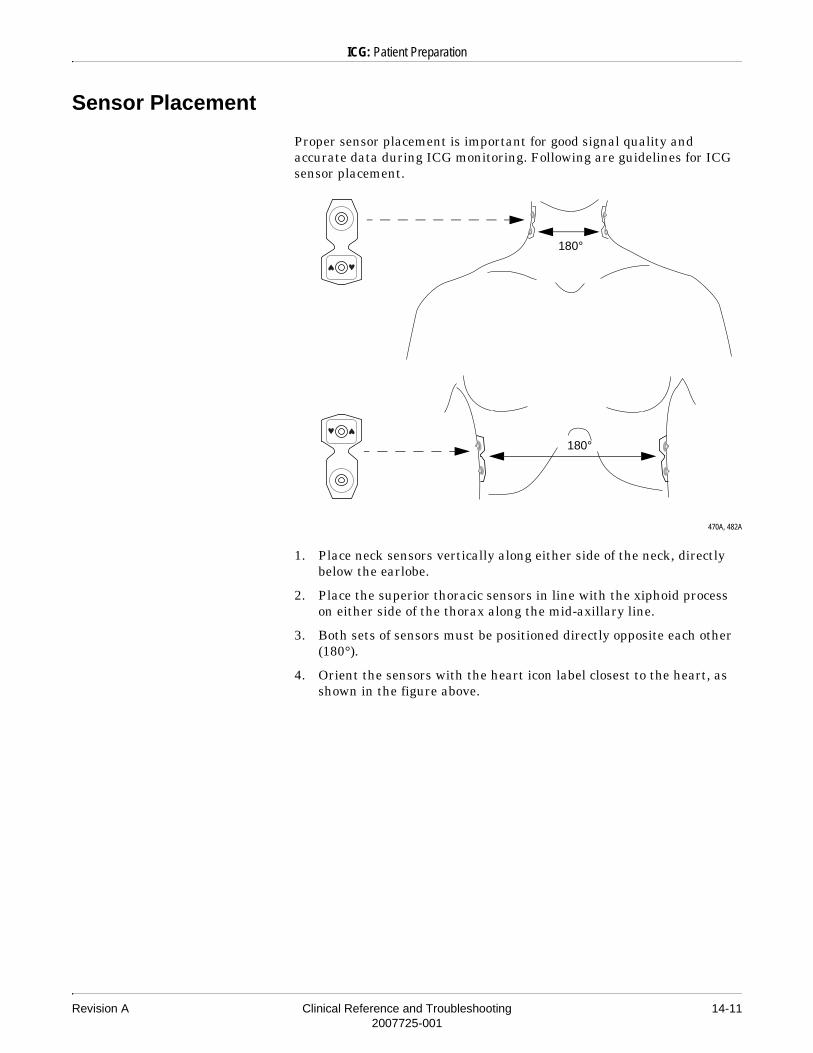
Revision A Clinical Reference and Troubleshooting 14-112007725-001
ICG: Patient Preparation
Sensor Placement
Proper sensor placement is important for good signal quality and accurate data during ICG monitoring. Following are guidelines for ICG sensor placement.
470A, 482A
1. Place neck sensors vertically along either side of the neck, directly below the earlobe.
2. Place the superior thoracic sensors in line with the xiphoid process on either side of the thorax along the mid-axillary line.
3. Both sets of sensors must be positioned directly opposite each other (180°).
4. Orient the sensors with the heart icon label closest to the heart, as shown in the figure above.
180°
180°

14-12 Clinical Reference and Troubleshooting Revision A2007725-001
ICG: Patient Preparation
Connecting the ICG Cable to the Patient
The ICG cable must be connected properly for ICG monitoring. Following are guidelines for connecting the ICG cable to the patient.
484A
1. Verify that the ICG right and left bundles correspond to the patient’s anatomical right and left sides.
2. Place cable across the patient’s neck with the cable facing toward the front. The icon should be visible to the clinician.
3. The cables are color-coded to ensure proper placement. Snap on the neck connectors first. Place the blue connector above the purple connector on each side of the patient.
4. Next, place the thorax connectors. The green connector goes above the orange connector.
5. When the patient connectors have all been properly placed, plug the cable into the connector on the front of the module.
Blue
Purple
Green
Orange

Revision A Clinical Reference and Troubleshooting 14-132007725-001
ICG: ICG Reference Literature
ICG Reference Literature
ICG Parameter Normal Range
Lessig ML, Lessig PM: The Cardiovascular System. In: Core Curriculum for Critical Care Nursing, 5th Edition (American Association of Critical-Care Nurses). Alspach JG (Ed) Philadelphia, WB Saunders Co, 1998.
Pinsky MR: Hemodynamic Profile. In: Principles and Practice of Intensive Care Monitoring. Tobin MJ (Ed) New York, McGraw-Hill, Inc., 1998.
Sramek BB. Hemodynamic and Pump Performance Monitoring by Electrical Bioimpedance. In: New Concepts. Problems in Respiratory Care. Vol. 2. Hicks GH (guest Ed). Philadelphia: JB Lippincott, 1989.
Gardner P. Pulmonary Artery Pressure Monitoring. AACN Clinical Issues in Critical Care Nursing, 1993.
ICG Technology
Storbeck JE, Silver MA, Ventura H. Impedance Cardiography: Noninvasive Measurement of Cardiac Stroke Volume and Thoracic Fluid Content. Congestive Heart Failure. 2000; Mar/Apr:3–6.
Osypka MJ, Bernstein DP. Electrophysiologic Principles and Theory of Stroke Volume Determination by Thoracic Electrical Bioimpedance. AACN Clinical Issues. 1999; 10(3).
Lasater M. The View Within: The Emerging Technology of Thoracic Electrical Bioimpedance. Critical Care Nursing Quarterly. 1998; 21(3).
Clonz, RL. Advances in Noninvasive Hemodynamic Monitoring. Medical Electronics. 1997.
Bernstein DP: Noninvasive Cardiac Output Measurement. In: Textbook of Critical Care, 2nd Edition. Shoemaker WC, Ayres S, Grenvik A, Holbrook PR, Thompson WL (Eds). Philadelphia, WB Saunders Co, 1989, p 159.

14-14 Clinical Reference and Troubleshooting Revision A2007725-001
ICG: ICG Reference Literature
For your notes

Revision A Clinical Reference and Troubleshooting 15-12007725-001
15 EEG Monitoring

15-2 Clinical Reference and Troubleshooting Revision A2007725-001
For your notes

Revision A Clinical Reference and Troubleshooting 15-32007725-001
EEG Monitoring: Introduction
Introduction
An EEG is a recording of the electrical activity of the brain. The amplitude of the electrical activity is measured in microvolts (µV). Comparatively, an ECG (electrocardiograph) is measured in millivolts (mV). The amount of electrical activity on an EEG is 1000 times smaller.
Definitions of Terms
Amplitude (AMP) A measure of the absolute total power in the frequency range from 0.5 to 30.0 Hz. Absolute power is reported in dB with respect to 0.0001 µ V2.
Bipolar Mode In the bipolar mode, each EEG channel is a differential signal measured from the negative (–) electrode to the positive (+) electrode. A reference electrode is not used. Nine electrodes are required for four-channel bipolar monitoring — four pairs (channel 1 “+” and “–”, channel 2 “+” and “–”, etc.) plus a ground (GND) electrode.
Compressed Spectral Array (CSA)
The compressed spectral array is a graphical representation of the power spectrum of the EEG as it changes over time. The CSA plot is a sequence of overlapping power spectrum plots, which provides a three-dimensional graphical representation of the EEG. The most recent power spectrum is displayed at the bottom of the CSA. The CSA allows you to see changes in the power distribution over time.
����If data peaks from one power spectrum plot overwrite earlier data, the earlier data is erased from the display.
Density Modulated Spectral Array (DSA)
The density modulated spectral array represents the amplitude of the power spectrum of the EEG by varying the intensity levels of a color (i.e., gray scaling) as it changes over time. Brighter points (white) correspond to a greater power content level of the EEG. Darker points (black) represent the least power content in the EEG.
Electromyograph (EMG) An electromyograph is the absolute power in the 70 to 110 Hz range. This frequency range contains power from muscle activity (electromyography), as well as power from other high-frequency artifacts.
Median Frequency (MedF) The frequency at which 50% of the total power lies to either side of it.
Montage The pattern of connections between the EEG electrodes and the recording channels.
Referential Mode In the referential mode, each EEG channel is a differential signal measured from the negative (–) electrode input to the reference (REF) electrode. The positive electrodes are not used. Up to four electrodes can be referenced to one reference electrode. For four-channel referential monitoring, six electrodes must be placed on the patient — one reference electrode, one ground (GND) electrodes, and four negative electrodes.
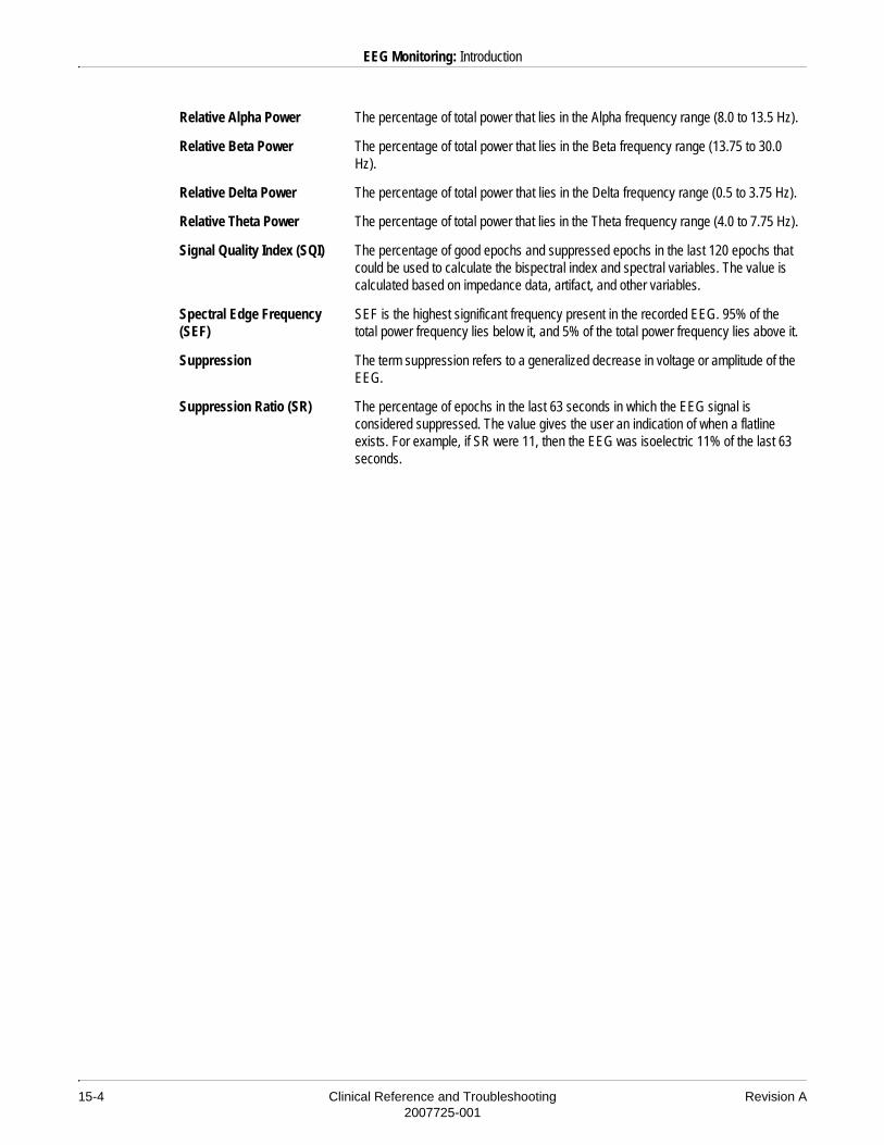
15-4 Clinical Reference and Troubleshooting Revision A2007725-001
EEG Monitoring: Introduction
Relative Alpha Power The percentage of total power that lies in the Alpha frequency range (8.0 to 13.5 Hz).
Relative Beta Power The percentage of total power that lies in the Beta frequency range (13.75 to 30.0 Hz).
Relative Delta Power The percentage of total power that lies in the Delta frequency range (0.5 to 3.75 Hz).
Relative Theta Power The percentage of total power that lies in the Theta frequency range (4.0 to 7.75 Hz).
Signal Quality Index (SQI) The percentage of good epochs and suppressed epochs in the last 120 epochs that could be used to calculate the bispectral index and spectral variables. The value is calculated based on impedance data, artifact, and other variables.
Spectral Edge Frequency (SEF)
SEF is the highest significant frequency present in the recorded EEG. 95% of the total power frequency lies below it, and 5% of the total power frequency lies above it.
Suppression The term suppression refers to a generalized decrease in voltage or amplitude of the EEG.
Suppression Ratio (SR) The percentage of epochs in the last 63 seconds in which the EEG signal is considered suppressed. The value gives the user an indication of when a flatline exists. For example, if SR were 11, then the EEG was isoelectric 11% of the last 63 seconds.

Revision A Clinical Reference and Troubleshooting 15-52007725-001
EEG Monitoring: EEG Electrodes
EEG Electrodes
EEG monitoring is accomplished through the use of electrodes placed on the scalp.
�� ���ELECTRODES — The EEG electrodes must have 1.5 mm DIN standard safety lead connectors.
The number of electrodes used is determined by the number of recording channels (4), and by the surgical procedure and location.
Several different types of electrodes are commercially available. Some of the most common types are cup electrodes, needle electrodes, and patch (adhesive) electrodes. Electrodes are generally silver/silver chloride or gold.
����All electrodes used must be of the same type. Do not mix electrodes (e.g., silver/silver chloride electrodes with gold electrodes).
Surface electrodes are recommended.
�� ���NEEDLE ELECTRODES — If needle electrodes are used, there may be an occasional loss of EEG signal or baseline wander that may appear like Delta waves.

15-6 Clinical Reference and Troubleshooting Revision A2007725-001
EEG Monitoring: EEG Electrode Placement
EEG Electrode Placement
There are various electrode placements that can be used for EEG monitoring. Some common placements are described in this section.
International 10-20 Electrode Placement System
The international 10-20 electrode placement system is the accepted worldwide standard of electrode measurement and application for all EEG procedures. The standard uses 10- and 20-percents in measuring the head.
There are 19 electrode positions on the head, excluding the ground electrode. These positions are measured in relation to standard anatomical landmarks on the skull and should be proportional to the skull’s size and shape. The anatomical landmarks are:� Nasion — the notch between the eyes.� Inion — located underneath the occipital protrusion.� Preauricular points — left and right, located at the notches of the
ears.
903A
Preauricular Point Preauricular Point
Nasion
Inion

Revision A Clinical Reference and Troubleshooting 15-72007725-001
EEG Monitoring: EEG Electrode Placement
How to Measure the Head for Electrode Placement
The following steps give a general overview of measuring the head for EEG electrode placement using the international 10-20 system.
1. Using a millimeter (mm) tape, measure the head from the nasion to the inion.
����A narrow (no wider than 5 mm), metal, retractable measuring tape is recommended. It will not stretch and can be wiped clean with alcohol or disinfectant after each use.
2. Use a non-toxic skin marking pen to make a mark on the patient’s head at 10% of the distance above the nasion. For example, if the distance from the nasion to the inion were 35 cm, you would make a mark 3.5 cm above the nasion.
3. Continue marking the patient’s head in a transverse direction at 20% intervals until only 10% of the total distance remains (above the inion). Continuing with the example used in step 2, you would make a mark at 7.0 cm, and every 7.0 cm after that.
4. When finished marking from the nasion to the inion, you should have made 5 marks on the patient’s head. These 5 lines fall on the frontal, central, parietal, and occipital planes.
5. Next, measure from the left preauricular point to the right preauricular point.
6. Mark the patient’s head at 10% of the distance from the left preauricular point to the right. For example, if the distance between preauricular points were 35 cm, you would make a mark 3.5 cm above the left preauricular point.
7. Continue marking the patient’s head in a coronal direction at 20% intervals until only 10% of the total distance remains. Continuing with the example used in step 6, you would make a mark at 7.0 cm and every 7.0 cm after that, across the patient’s head.
8. When finished marking from the left preauricular point to the right, you should have made 5 marks across the patient’s head. These 5 lines fall on the temporal, central, and mid-central planes.

15-8 Clinical Reference and Troubleshooting Revision A2007725-001
EEG Monitoring: EEG Electrode Placement
As shown in the illustration found on page 15-6, each electrode position is labeled. For example, an electrode on the frontal plane would be labeled “F”. Even-numbered electrodes are on the right side of the head, and odd-numbered electrodes are on the left. Electrodes designated with the letter “Z” rather than a number are located on the mid-line areas, e.g., Fz, Cz, Pz.� Fp — prefrontal or frontal pole� F — frontal� C — central� P — parietal� O — occipital� T — temporal
Regional Lead Placements
It is not always possible or desirable to place a lead in the standard international 10-20 lead configuration. In these cases, regional lead placement positions, which place the lead over a more generalized brain area, can be selected at the host monitor. Refer to your monitor operator’s manual for more information.
The electrode positions for regional lead placements are labeled as indicated below:� LFp — left prefrontal� LF — left frontal� LO — left occipital� LP — left parietal� LT — left temporal� RFp — right prefrontal� RF — right frontal� RO — right occipital� RP — right parietal� RT — right temporal
Revision A Clinical Reference and Troubleshooting 15-92007725-001
EEG Monitoring: EEG Electrode Placement
Generic “X” Lead Placement
A generic “X” lead placement option is also offered. This is used to indicate that an EEG electrode has been placed in any location other than those in the international 10-20 electrode placement system and/or in a regional lead placement. The generic “X” lead placement can be selected at the host monitor. Refer to your monitor operator’s manual for more information.
Commonly Used Electrode Montages
The list below provides some common two- and four-channel electrode montages. These montages are suggestions only. Other electrode combinations may also be used. Use the montage that best suits your clinical needs.
�����ELECTRODES — EEG electrodes must NOT be located between defibrillator pads when a defibrillator is used on a patient connected to the BIS/EEG module. Death or serious injury could result.
In all montages, the ground electrode should be placed above the shoulder at the base of the skull, on the forehead, or on one of the mastoid processes (if it is not already used for an electrode).
The electrode placement for the ground electrode can be assigned to one of the international 10-20 electrode placement system positions, to a regional position, or to the generic “X” position if it is not placed in one of the positions recommended above.

15-10 Clinical Reference and Troubleshooting Revision A2007725-001
EEG Monitoring: EEG Electrode Placement
Four-Channel Montages
The montages described in the following tables are the host monitor default montages for four-channel bipolar and four-channel referential monitoring.
Two-Channel Montages
The montages described in the following tables are the host monitor default montages for two-channel bipolar and two-channel referential monitoring.
Channel (Bipolar) – +
Channel 1 F7 T3
Channel 2 F8 T4
Channel 3 Fp1 C3
Channel 4 Fp2 C4
Channel (Referential) – REF
Channel 1 F3 Cz
Channel 2 F4 Cz
Channel 3 A1 Cz
Channel 4 A2 Cz
Channel (Bipolar) – +
Channel 1 Fp1 A1
Channel 2 Fp2 A2
Channel (Referential) – REF
Channel 1 A1 FpZ
Channel 2 A2 FpZ
Revision A Clinical Reference and Troubleshooting 15-112007725-001
EEG Monitoring: EEG Electrode Placement
Skin Preparation
Proper cleaning and preparation of the electrode site is necessary for a good quality signal, which will optimize operation of the BIS/EEG module.
Prepare the patient’s skin according to the electrode manufacturer’s recommendations. Following are suggested procedures.
Skin Preparation for Surface Electrodes
To prepare the skin for surface electrode placement (e.g., cup, disk, pregelled disposable), follow these steps:
1. Clean the location of each electrode site with alcohol.
2. Using a cotton swab moistened with an abrasive gel, such as Nuprep™, gently rub each electrode site. Use a circular motion and abrade an area slightly larger than the diameter of the electrode. Be careful not to scratch or break the skin.
3. Remove any excess abrasive gel from the patient’s skin.
Skin Preparation for Needle Electrodes
Surface electrodes are recommended. See the manufacturer’s recommendations for needle electrode skin preparation.
Skin Preparation for Patch (Adhesive) Electrodes
Following is a suggested skin preparation for patch (adhesive) electrodes. This procedure is only a suggestion. Be sure to read the manufacturer’s instructions for skin preparation when adhesive electrodes are used because the skin preparation required varies by the type of electrode being used.
1. Shave hair from skin at chosen sites.
2. Gently rub skin surface at sites to remove dead skin cells.
3. Thoroughly cleanse the site with alcohol or a mild soap and water solution. Be sure to remove all oily residue, dead skin cells, and abrasives. Leftover abrasion particles can be a source of noise.
4. Dry the skin completely before applying the electrodes.
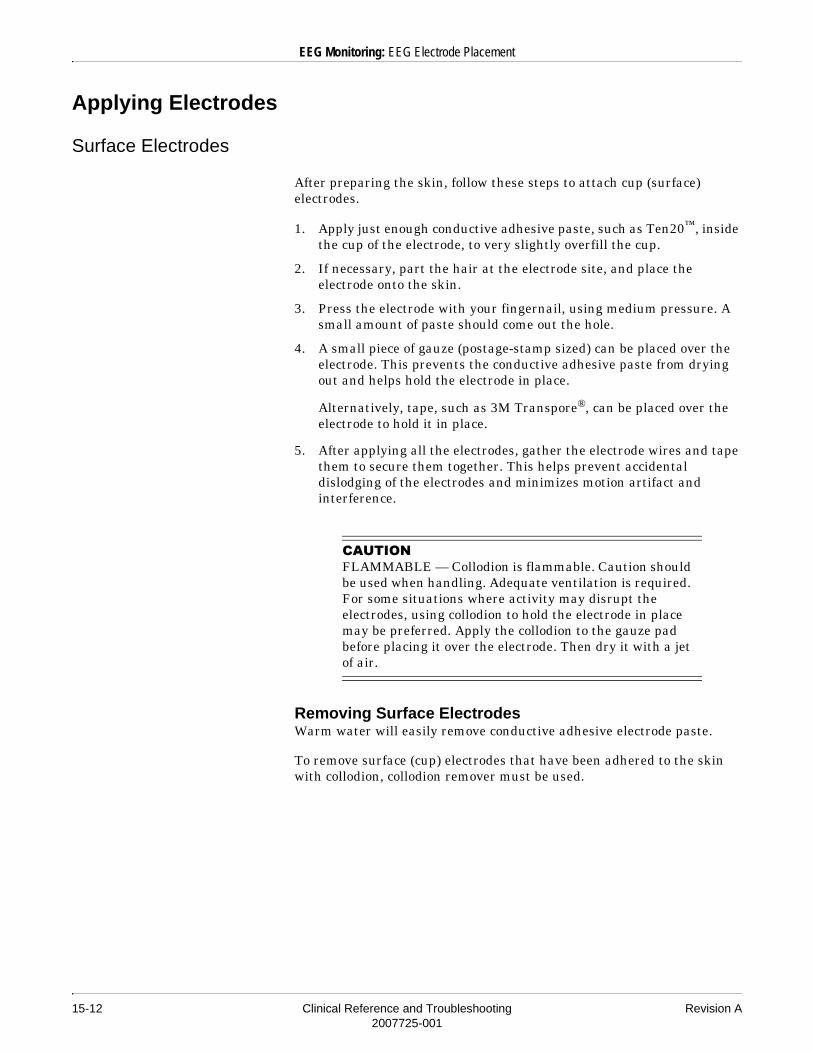
15-12 Clinical Reference and Troubleshooting Revision A2007725-001
EEG Monitoring: EEG Electrode Placement
Applying Electrodes
Surface Electrodes
After preparing the skin, follow these steps to attach cup (surface) electrodes.
1. Apply just enough conductive adhesive paste, such as Ten20™, inside the cup of the electrode, to very slightly overfill the cup.
2. If necessary, part the hair at the electrode site, and place the electrode onto the skin.
3. Press the electrode with your fingernail, using medium pressure. A small amount of paste should come out the hole.
4. A small piece of gauze (postage-stamp sized) can be placed over the electrode. This prevents the conductive adhesive paste from drying out and helps hold the electrode in place.
Alternatively, tape, such as 3M Transpore®, can be placed over the electrode to hold it in place.
5. After applying all the electrodes, gather the electrode wires and tape them to secure them together. This helps prevent accidental dislodging of the electrodes and minimizes motion artifact and interference.
�� ���FLAMMABLE — Collodion is flammable. Caution should be used when handling. Adequate ventilation is required. For some situations where activity may disrupt the electrodes, using collodion to hold the electrode in place may be preferred. Apply the collodion to the gauze pad before placing it over the electrode. Then dry it with a jet of air.
Removing Surface ElectrodesWarm water will easily remove conductive adhesive electrode paste.
To remove surface (cup) electrodes that have been adhered to the skin with collodion, collodion remover must be used.

Revision A Clinical Reference and Troubleshooting 15-132007725-001
EEG Monitoring: EEG Electrode Placement
Adhesive Electrodes
Adhesive electrodes can only be applied to skin that does not have hair. In the case of EEG monitoring, application of adhesive electrodes is generally limited to the forehead. Follow the manufacturer’s instructions for proper adhesion.
Connecting the Electrodes to the EEG DSC
After the electrodes have been properly applied to the patient, each electrode leadwire should be connected to the proper connector on the EEG DSC (digital signal converter). Plug each leadwire firmly into the connector.
The EEG DSC has connection points for 10 electrodes, including a reference electrode and a ground electrode.
The negative (–) electrode connectors are used for both referential and bipolar monitoring.
The bipolar (+) connectors are of positive polarity and are used for bipolar monitoring.
The REF connector is used for the reference electrode during referential monitoring.
The GND connector is used for the ground electrode. A ground electrode must always be connected for both bipolar and referential monitoring.
The EEG DSC has green indicator LEDs that show whether it is in bipolar or referential monitoring mode and indicate which electrode input connectors to use.
The attachment clips on the EEG DSC are used to secure it. The EEG DSC should be secured as close to the patient as possible during EEG monitoring.

15-14 Clinical Reference and Troubleshooting Revision A2007725-001
EEG Monitoring: EEG Reference Literature
EEG Reference Literature
Archibald John E, Drazkowski Joseph F: Clinical Applications of Compressed Spectral Analysis (CSA) in OR/ICU Settings. American Journal of EEG Technology 1985; 25:13-36.
Buzea, Cynthia E: Understanding Computerized EEG Monitoring in the Intensive Care Unit. Journal of Neuroscience Nursing 1995; 27 (5): 292-297.
Rampil Ira J: A Primer for EEG Signal Processing in Anesthesia. Anesthesiology 1998; 89 (4): 980-1002.
Russell Garfield B, Rodichok Lawrence D: Intraoperative Neurophysiologic Monitoring. Boston: Butterworth-Heinemann, 1995.
Revision A Clinical Reference and Troubleshooting 16-12007725-001
16 BIS Monitoring

16-2 Clinical Reference and Troubleshooting Revision A2007725-001
For your notes
Revision A Clinical Reference and Troubleshooting 16-32007725-001
BIS Monitoring: Introduction
Introduction
The Bispectral Index™ (BIS) is a processed EEG variable which may be used as an aid in monitoring the effects of certain anesthetic agents, and is intended for use under the direct supervision of a licensed healthcare practitioner or by personnel trained in its proper use. BIS is intended for use on adult and pediatric patients within a hospital or medical facility providing patient care to monitor the state of the brain by data acquisition of EEG signals.
The BIS is computed in real-time using three steps:
1. The raw EEG signal is broken down second by second, and the segments that have artifact are identified and removed.
2. The bispectral index is calculated by combining EEG features associated with anesthetic effect.
3. The index is modified to reflect the amount of suppressed EEG signal in the raw waveform.
Considerations for Using BIS
Clinical judgement should always be used when interpreting the BIS in conjunction with other available clinical signs.
�� ���BIS — Reliance on the BIS alone for intraoperative anesthetic management is not recommended.
As with any monitored parameter, artifacts and poor signal quality may lead to inappropriate BIS values. Potential artifacts may be caused by poor skin contact (high impedance), muscle activity or rigidity, head and body motion, sustained eye movements, improper sensor placement and unusual or excessive electrical interference. Due to limited experience in the following applications, BIS values should be interpreted cautiously in patients with known neurological disorders, those taking psychoactive medications, and in children below the age of one.

16-4 Clinical Reference and Troubleshooting Revision A2007725-001
BIS Monitoring: Safety
Safety
Warning
�����SENSOR — The BIS sensor must NOT be located between defibrillator pads when a defibrillator is used on a patient connected to the BIS/EEG module. Death or serious injury could result.
Cautions
� AUTOCLAVE — Do not autoclave the digital signal converter. Autoclaving will seriously damage the component.
� COMPONENTS — Do not cut sensor components, as this can result in improper operation.
� DIGITAL SIGNAL CONVERTER — Do not open the digital signal converter for any reason. The seal to prevent liquids from entering the digital signal converter may be damaged if opened. Service or repairs must be performed only by qualified biomedical technicians.
� DRYOUT — Do not use sensor if sensor is dry. To avoid dryout, do not open pack until ready to use.
� IMPEDANCE CHECK — Continuous impedance checking may need to be disabled if the impedance check signal interferes with other equipment.
� SENSOR — The BIS/EEG module has been designed to operate with a disposable BIS sensor. The sensor is a silver/silver chloride electrode array that utilizes Aspect Medical Systems patented Zipprep® technology and uses a proprietary connector. Do not use other types of electrodes.
� SHORT-TERM USE — The sensor is limited to short-term use (maximum of 24 hours).
� SINGLE USE — The sensor is for single use only. Do not reuse. Due to skin contact, reuse may pose a risk of infection.
� SKIN IRRITATION — If a skin rash or other unusual symptom develops, discontinue use of the sensor and remove.

Revision A Clinical Reference and Troubleshooting 16-52007725-001
BIS Monitoring: BIS Sensor Placement
BIS Sensor Placement
There are two types of BIS sensors, a three-electrode sensor and a four-electrode sensor. Follow the appropriate placement instructions, based on how many electrodes your sensor has.
Three-Electrode Sensor Placement
1. Wipe skin with alcohol and dry.
2. Apply sensor on forehead. Position circle number 1 at center of forehead, approximately 1.5 inches (4 cm) above nose, and circle number 3 on temple area between corner of eye and hairline.
3. Press edges of sensor to assure adhesion.
4. Press circles 1, 2 and 3 firmly for 5 seconds to assure proper contact.
5. Insert sensor tab into patient interface cable until fully engaged.
6. When disconnecting sensor, press release button on the patient interface cable.
����Upon removal, slight redness of skin may be seen and is typically resolved within a short period of time.
Three-Electrode Sensor Placement
919A

16-6 Clinical Reference and Troubleshooting Revision A2007725-001
BIS Monitoring: BIS Sensor Placement
Four-Electrode Sensor Placement
1. Wipe skin with alcohol and dry.
2. Apply sensor on forehead at angle. Position circle number 1 at center of forehead, approximately 2 inches (5 cm) above nose, circle number 4 directly above and parallel to eyebrow, and circle number 3 on temple area between corner of eye and hairline.
3. Press edges of sensor to assure adhesion.
4. Press circles 1, 2, 3 and 4 firmly for 5 seconds to assure proper contact.
5. Insert sensor tab into patient interface cable until fully engaged.
6. When disconnecting sensor, press release button on patient interface cable.
Four-Electrode Sensor Placement
918A

Revision A Clinical Reference and Troubleshooting 16-72007725-001
BIS Monitoring: BIS Range Guidelines
BIS Range Guidelines
The bispectral index is an absolute value, so baseline information about the patient is not required for BIS monitoring. The table below indicates the BIS values and their significance.
Titration of sedatives to BIS ranges should be dependent upon the individual goals for sedation that have been established for each patient. These goals and associated BIS ranges may vary over time and in the context of patient status and treatment plans.
BIS Value Patient State Comments
100 Awake Patient responds to normal voice.
80 Moderate Sedation Patient responds to loud commands or mild prodding/shaking.
60 Deep Sedation Patient has low probability of explicit recall and is unresponsive to verbal stimulus.
20 Deep Sedation Burst suppression.
0 Flat line EEG No brain activity detected.

16-8 Clinical Reference and Troubleshooting Revision A2007725-001
BIS Monitoring: BIS Spectral Displays
BIS Spectral Displays
A BIS spectral display can be displayed on compatible GE Medical Systems Information Technologies host monitors. The display shows the EEG data in one of three plot formats: DSA Pixel, DSA Shade, or CSA.
The Compressed Spectral Array (CSA) is a graphical representation of the power spectrum of the EEG as it changes over time. The power spectrum is a histogram of the power content at each frequency. The CSA plot is a sequence of overlapping power spectral plots, which provide a three-dimensional pictorial representation of the EEG. The CSA allows you to observe changes in the power distribution over time. The disadvantage of the CSA is that traces with large amplitudes at a particular frequency can obscure earlier plots of smaller amplitude signals.
The Density Modulated Spectral Array (DSA) allows you to observe changes in the power spectrum distribution over time. The DSA is similar to the CSA plot in that it also displays a sequence of power spectral plots. However, the DSA overcomes the overlapping characteristic of the CSA plots by representing the amplitude of a power spectrum point in varying intensity levels of a color (i.e., gray scaling), with brighter points corresponding to greater power content.

Revision A Clinical Reference and Troubleshooting 16-92007725-001
BIS Monitoring: BIS Reference Literature
BIS Reference Literature
Arbor Richard B: Using the Bispectral Index to Assess Arousal Response in a Patient with Neuromuscular Blockade. American Journal of Critical Care November 2000; 9 (6): 383-387.
Bowdle T. Andrew: The Bispectral Index (BIS): Routine Measurement of Depth of Hypnosis during Anesthesia. Current Reviews in Clinical Anesthesia 1999; 19 (16): 169-180.
Rosow Carl, Manber Paul J: Bispectral Index Monitoring. Anesthesiology Clinics of North America 1998; 2: 1084-2098.
Sigl JC, Chamoun NC: An Introduction to Bispectral Analysis for the EEG. J Clin Mon 1994; 10: 392-404.

16-10 Clinical Reference and Troubleshooting Revision A2007725-001
BIS Monitoring: BIS Reference Literature
For your notes


World HeadquartersGE Medical SystemsInformation Technologies, Inc.8200 West Tower AvenueMilwaukee, WI 53223 USATel: + 1 414 355 5000
1 800 558 5120 (US only)Fax: + 1 414 355 3790
European RepresentativeGE Medical SystemsInformation Technologies GmbHMunzinger Straße 3-5D-79111 FreiburgGermanyTel: + 49 761 45 43 - 0Fax: + 49 761 45 43 - 233
Asia HeadquartersGE Medical SystemsInformation Technologies Asia; GE (China) Co., Ltd.24th Floor, Shanghai MAXDO Center,8 Xing Yi Road, Hong Qiao Development ZoneShanghai 200336, P.R. ChinaTel: + 86 21 5257 4650Fax: + 86 21 5208 2008
gemedical.com