CRITERIA FOR DESIGN OF BEARING PADS - pci.org Resources... · FOR DESIGN OF BEARING PADS ......
114
Technical Report 1\'0. 4 CRITERIA FOR DESIGN OF BEARING PADS .James K. Iverson and Donald W. Pfeifer o prestressed concre1e nstJtute
Transcript of CRITERIA FOR DESIGN OF BEARING PADS - pci.org Resources... · FOR DESIGN OF BEARING PADS ......

Technical Report 1\'0. 4
CRITERIA FOR DESIGN OF BEARING PADS
.James K. Iverson and Donald W. Pfeifer
o
prestressed concre1e nstJtute

Copyright ,c: 1985 By Prestressed Concrete Institute
All rights reserved. This book or any part thereot may not be reproduced in any form without the written permission of the Prestressed Concrete Institute,
library of Congress Catalog Card Number 85-61825 ISBN 0-937040·24-X
Printed In U.S.A,

1 A13LE 01- CONTFNTS
INTRODUCT ION ....................................................... Gpnera L ••••.. Types of Pads Haterial and Design Specifications Purpose. and Direction for this Study
..
REVIEW OF CURRENT PRACTICE AND PROBLE~S ............................ Haterials . . . . . . . .. .. ..... Design Guidance
SURVEYS AND SITE VISITS
PCI Membership Survey . . . . . . . Site Visits .••••••••••• Collection of [nformation from Pad .'-Ianufacturers
n:ST1NG PROGRAM
Compression Test"l Simple Chlorapr-ene Shear Tests Creep Tests
Verification Test
.... . ...
..
....
DISCUSSION ........................................................ General
on Compression for Chloroprenc Current Recommendations Bridge Bearing Pads ........................................
Compressive Stress-Strain Properties of Building Bearing Pads ..•••.•.••••.•.••
Rotation and Shear DeCormat ions ••• F ri ct ion and Slippage ....... Creep Characteristics •••••••
DES[GN RECOHHENUATIONS
Plain Chloroprene Pads Random Fibcr Reinforced Pads Duck Layer Reinforced Pads Chloroprene Identification Test Future Research
...
i
..
..
2 3 3
5
5 10
13
13 15 16
18
Ie 27 28 37
41
41
41
42 45 4S 62
64
64 68 70 71 72

TABLE OF CONTENTS
SUMHARY AND CONCLUS IONS ••••••••••••••••••••••••••••••••••••••••••••••
Surveys and Site Visits •••••••••••••••••••••••••••••••••••••••• Laboratory Testing ••••••••••••••••••••••••••••••••••••••••••••• Literature Review •••••••••••••••••••••••••••••••••.•• 0 ••••••••
Re commendat ions .............................................
REFERENCES ..........................................................
APPENDIX 1 - Sl/MHARY OF PCl PRODUCERS SURVEy ••••••••••••••••••••••••••
72
73 74 74 75
77
79
APPENDIX 2 - SUMHARY OF SIn: VISIT INFORMATION AND TESTS. •••••• ....... 82
APPENDIX 3 - SPECTROPHOTOMETER ANALYSIS OF BEARING PAD SAt1PLES........ 96
APPENDIX 4 - RECOHMENDED PCI DESIGN HANDBOOK SECTION ON BEARING PADS.. 105
it

General:
CRITERIA
FOR DESIGN OF
BEARING PADS
INTRODUCTION
Bearing pads are essential in construction with precast con
crete. They provide two primary design functions both intended
to minimize undesirable stresses in the adjacent concrete:
1) To obtain more uniform distribution of concentrated
loads.
Z) To allow movement and minimize the effects of loads due
to volume changes from shrinkage, creep and tempera
ture.
Problems and failures have occurred due to poor materials or
improper use of bearing pads, but the majority of experience has
demonstrated their beneficial effects.
In the past, the most commonly used elastomeric bearing pads
could be divided into two general groups; unreinforced plain pads
made of elastomer, and laminated pads made of elastomer rein-
forced with parallel horizontal steel plates. Small size plain
pads are used throughout the construction industry, whereas the
larger, more expensive, reinforced, laminated pads are used pri
marily for bridge bearings.
Pads reinforced with both random oriented fibers and layered
fiber material are available and their use is increasing in
building construction. These newer pads bridge the gap between
the large steel laminated pads and the plain unreinforced pads.
One of the difficulties in designing bearing pads stems from
the large number of companies producing similar competing pro
ducts which often have different physical properties and capabil
ities. Generally, a few large chemical companies produce the
-1-

basic raw elastomer, but they do not produce the final bearing
pad product. This operation is left to the numerous pad produ-
cers, who buy the raw material. fornulate it with a number of
fillers and enhancers, vulcanize it with or without reinforcment,
and cut the final pad. This company may in turn sell the bearing
pads to other suppliers or distributors and the final user or de
signer finds it difficlllt to determine the actual composition and
mechanical properties for the pad.
!z.pes of Pads
The most common types of bearing pads used today are:
- Chloroprene (Neoprene) is probably the most commonly used
pad.
- Random oriented fiber (ROF) reinforced elastomeric pads
are made from excess materials from the tire industry,
with short fihers randomly oriented throughout the materi
al.
- DUck layer reinforced (DLR) pads are generally of chloro
prene or similar elastomer with horizontal layers of woven
duck fiber reinforcing at extremely close spacing.
Laminated elastomeric. pads with reinforcing layers of
steel or fiberglass are commonly used for bridge bearings.
Natural rubber is c.ommonly USed in ~:urope but seldom used
in the United States.
- Plastic pads
Stee_l plate
- Low friction materials such as teflon or TFE (poly tetra
f louroethylene) are most often used in conjunction with
other bearing materials, to provide a slip surface.
- A number of materials, such as bituminous joint filler,
hardboard, wood and similar filler materials have been
used, but these materials are not generally considered as
reliable structural bearing materials.
-2-

Haterial and Design Specifications
At present. the design guidance for these various pads comes
primarily from the American Association of State Highway and
Transportation Offieia1s (AASHTO) Speeification,(l)* State High
way Departments, and the Prestressed Concrete Institute (PCl)
Handbooks. (2, 3) Most of the design information and material on
plain chloroprene pRds is based on Ou Pont research and design
recommendations published in 1959. (4)
AASHTO provides a material specification for chloroprene and
natural rubber bearing pads in Section 25 of their Standard Spe
cifications(l). Article 2.10.3(L) also provides a brief descrip
tion of duck layer reinforced pads that falls short of being a
complete specification. Hilitary specification flIL-C-882C also
covers duck layer reinforced pads and a number of State Highway
Departments have sections in their standard specifications deal
ing with bridge bearing pads.
Design informatIon and specifications for the numerous types
of small pads used in bui lding construction are not covered to
any extent by standard specifications. The general sources of
design guidance for small pRds are the PCI handbooks (2. 1) and
manufacturers brochures which apply to a particular product.
Purpose and Direction for this Study
The purpose of this study is to better understand pad behav
ior and development of appropriate design criteria for bearing
pads to be included in the PCI Design Handbook. This study has
been accomplished in accordance with the following five tasks
outlined in the PCI request for proposals and detailed in further
directions from the following advisory committee appointed by
PCI:
*References at end of report
-3-

Member
Daniel P. Jenny
Anthony L. Schloss
T • .!. Gutt
Kenneth \Tick
Thomas J. Lechner
James R. Voss
J oho M. Hans on
Advisory Committee
Affiliation
Technical Director, P.C.I.
E. r. duPont deNemours & Company,
Elastomers Division
TPAC Division of the Tanner Companies
Spancrete Industries, Inc.
Voss Engineering, Inc.
.lVI, Inc.
Wiss. Janney. Elstner Associates, Inc.
Research Tasks
Task 1 - "Conduct a survey of the membership of the Insti
tute to obtain information on problems that have been encountered
with uSC' of bearing pads in buildings."
Task 2 - "Investigate a selected number of the problems
identified in Task 1, by making site visits and carrying out
analyses to determine conditions that caused these problems."
Task 3 "Collect and synthesize all current information on
pads that are suitahle for bearings of precast members."
Task 4 - "To the extent that resources are available, COn
duct tests to evaluate the performance of selected bearing pad
materials. "
Task 5 - "Using the information collected in Tasks 1 through
4 develop appropriate design criteria for precast concrete con
struction. These criteria along with supplemental design aids
are to be developed in a form suitable for inclusion in the In
dustry Design Handbook. "
A primary direction emerged during the early committee dis
cussions. Since the PCI Design Handbook is currently under revi
sion, the Industry Handbook Committee determined that the new
edition would be clearly directed to serve design of
prestressed concrete in buildings and it would not
serve the bridge construction industry. As a result,
tat ion of this study was directed toward buildings.
-4-
precast and
attempt to
the orien
The primary

r------------------ -, , , UNDEFORMED PAD
~ _____ ~~r--_ BULGE
I
Fig. 1 - Bulging of unrejnforcerl elastomeric pad under compressive load
-)-

elastomer to flow or act similarly to an inflated inner tube
leads to many of its desirable qualities. Such pads can accommo
date small irre.gularities in the loading surfaces, absorb small
amounts of rotation and horizontal movement between the two load
ing surfaces and still support and transfer compression loads.
This flowability can also contribute to slippage problems. The
designer's task is to choose a pad that will take the loads and
movements without excessive deformation or gross slippage. An
example of an unreinforced chloroprene pad is shown in the center
of Fig. 2.
Duck layer reinf arced pads are generally produced with
chloroprene or nitrile elastomers used to bond closely spaced
horizontal layers of woven duck fiber material together. The re
sulting pads are more costly and have TIIlch higher co~ressive
load capacities than unreinforced pads since the reinforcing min
imizes bulging and deformation. However, shear, rotation and ir
regularities are less easily accommodated than with the unrein
forced ehlotoptene pads. A sample of this pad type is shown on
the right in Fig. 2.
The random oriented fiber reinforced pads are a recently in
troduced pad type. They are generally produced from excess vir
gin tire production material. the material is processed by chop
ping the tire fibers, adding ozone retardant and then vulcaniZing
into sheets. These sheets are then cut to si;::e. Again, the ran
dom fiber reinforcement reduces the usual pad bulging character
istic and allows higher compressive loads, but the material is
somewhat stiffer and accommodates irregularities, rotation and
shear movements less easily. A safl{lle of this type of pad is
shawn on the left in Fig. 2. Some variability is noted in these
pads, such as, fiber type (nylon. rayon, etc.), fiber distribu
tion, and elastomeric composition.
Plastic is not commonly used for bearing pads except under
solid or hollow-core concrete slabs. It is used for shims under
precast wall panels and columns. Two companies manufacture such
-8-

, '" ,
Fig. 2 - Samples or random-fiber r ein fo r ced, chlo r oprene and duck layer reinforced pads

a product. The material is considered advantageous for shims be
cause it creeps slightly and transfers some load to the grout
bed. The material essentially does not bulge. and it has high
compressive load capability. It is relatively hard and has more
limited ability to conform to surface irregularities, rotations
or shear movements than the elastomeric pads. No standard in-
dustry specifications are known to exist for this material.
Steel pads arc used in heated buildings where movements will
be a mininum and where little surface irregularity is encoun
tered. They also are used for shi~~ similarly to the plastic ma
terial discussed above. The steel has very high compressive load
capability. but no ability to accommodate surface irregularitjes.
rotation or horizontal shear. If used as shims it does not creep
to allow transfer of Load to grout, and spalling at the shims may
result.
TFE or teflon is often used with stainless steel to provide
an extremely law friction surface that can slip to accommodate
horizontal movement and still transfer high vertical loads.
These low friction materials have also been coated on other bear
ing pad materials such as duck layer reinforced pads.
Finally, a number of miscellaneous materials, such as hard
board, wood and other absorptive materials have been used as pads
and have sometimes cansed problems through collapse of the pad or
staining or spalling of the concrete.
Oesign Guidance
Current AASHTO Specifications, although often used, are now
considered outdated and are currently under study(5,6, 7) for re-
vision. (1ost State Highway Departments use these guidelines
which are clearly directed toward large pads with heavy loads.
Bridge pad design is conservative since these pads will be used
in extreme environmental conditions with heavy moving loads and
genentlly provided little or no maintenance.
-10-

The design of pads for buildings are covered in the pel De
sign Handbooks or various pad manufacturers' brochures. The man
ufacturers' brochures are limited to each manufac:turer's data and
often do not provide sufficiently broad design values for the dc-
signers use.
The first part of the study to update the AASHTO bridge pad
design specification is covered in NCHRP Report 248(5). This
comprehensive report is of interest as it also summarizes the
most commonly used foreign des ign requirements. it appears that
significant research has been undertaken on bearing pads in
Europe. Table 1, which summarizes these design requirements aod
notation for large, plain ,.hloroprcoe pads for bridges, is taken
directly from this NCHRP report. The three foreign bridge codes
and the AASHTO specifications that are summarized are representa
tive of current world practice. The UIC 772R Specirication(8) is
developed by the International Union of Railway;; and is used in
Europe and some other parts of the world by both railway and
1/76(9) is a British code and is highway authorities. The BE
stated to be the most widely used elastomeric bearing specifica-
tion in the world. It is used in Britain, Australia and in r:oun-
tries in Europe and Asia. The design methods were particularly
developed for reinforced-laminated bearings of natural rubber but
they are widely used with chloroprene. BS5400(10) is a draft
British Standard and represents current thought on this subject
in Britain. It represents a combination of BE 1/76 and UTe 772R.
These foreign codes are generally based on considerable testing
or theory and tend to be more complex than AASHTO Specifications.
However. if favorahle design conditions with mini~lm movements
are encountered, mlch higher compressive stresses are allowed
when co~ared will AASHTO particularly on pads with large shape
factors. It is useful to note again that these codes all are
dealing with large bridge bearing pads, where small plain pads
tend to be relegated to a secondary position.
A discussion on German practice is warranted. Design ca1cu
lations are simplified, and only a few standardized sizes and
-11-

~
N ,
TABLE 1 - INTERNATIONAL BRIDGE CODE COMPARISONS FOR PLAIN PADS (F.!'EtII NCHRP Report)
ALlOIoiABLE SHEAR DISPLACEMENT
ule 772R
"'s ~O,7 T
BS 5400
"'s~O.7T
Br l/7!i MSHTD
"'s < 0.5 T Ih;I+I";I< D,S T
-------------------ALLOWABLE YERTlCAL DISPlACDIENT
VERTlCAL DEFLECTION EQUATION
SHAPE FACTOR
LIHITING CRITERIA FOR ALLOWABLE LOAD P
STABILITY REQUfREHEHTS
SLIP REQUIREHEHT
NOTATION:
A ~ lW
"'c~O,lST
To'c
" lOGS + Z"c
P , ., , "
LW S .. 2f{ L + wl
"c < 2GS
T ~ LIS
~ W/S
a > 145 (l + ~) psi , -
Are· (L - 0s)W ~ reduced effective area
.... s = Shear Deflection
hc = Compressive Deflection
T Total pad thickness
L Length (Parallel to Beam Centerline)
To be specified by engineer
PT , " , " 1 • 1
SGS2 K
LW S • 3.6T(l + '00')
"c 0( 2GS
T < 1
~ W/5
a > 145 (I t~) psi , -
E Young's Modulus with unrestrained lateral displacement
fc ~ Campres:>lve modulus with lateral displacement restrained
k Material constant depending on hardness
K Material bulk modulus in compression
6c <0.1T
" I.BPT
~ I 1 • 1 ~ ---r.8K 1
Ec = EO + 2kS2)
LW S • 3.6TtL + WJ
EB Vt .. Ys + Yc ~ ~
Y s = !.is. y = 65(" T' ,
I.8P Cc E(1 t 2kS2)A
T 0( L/4
~ W/4
'" DC > x- (concrete)
> '" X- (steel)
6. < o.on , -
None
LW S~2T{L+wl
" .. .e. 0( 800 psi , "provided
t. < 0.07 T , -
00' P t~SOOPSi
T ~ LIS
< WIS
DC > 200 1"51
due to D.L
min. compo load 8 Ratio ma~. shearing force In BE 1/76 W Width (perpendicular to Beam Centerline
ac • Average Compressf~e Stress
G Shear Modulu~
S Shape Factor
Ii Horizontal Force
P Allowable Load
Y Shear strain as per subscript ~ ~ A~erage compr~~~ive strain

shapes of pad using a single elastomer are used. All pads are
proof tested and each manufacturer must pass a rigorous certifi-
cation procedure. The results from this concept have apparently
been very satisfactory but pads are quite costly and the concept
tends to restrain new developments.
SURVEYS AND SITE VISITS
The survey work involved in Tasks 1, 2 and 3 involved:
PCI :1embership Survey
Site Visits
Collection of Data and Information
PCI Membership Survey
This work was performed with a controlled combination letter
and telephone survey of selected producer members. Twenty-one
PCI member companies were selected across the U.S.A. and Canada.
An 1nitial letter outlining the followup telephone survey was
sent to each company. Following their study of this letter ques
tionnaire, telephone contact was made and their responses were
noted as outlined in Appendix 1.
Significant comments on responses from the Survey are:
1. Four respondents or about 20 percent felt they had
bearing pad problems. However, these problems were re
lated to only a few projects.
2. Six respondents or about 30 percent felt that they ex
perienced limited bearing pad proble~~.
3. About 60 percent of the respondents used the pel or
slightly modified PCl criteria for their pad design.
4. The remaining respondents used rule-of-thumb procedures
to select pads, relied on the building designer to pro
vide pad design, or used pad manufacturer's data.
5. AASHTO-grade plain chloroprene (neoprene) was the most
commonly used pad material (60 percent used it as a
primary material). Two respondents with no problems
used AASHTO-grade exclusively, whenever possible.
-13-

Random-oriented fiber pads were also used hy 60 per-
cent. Four producers, or 20 percent, use random fiber
pads as their primary material, while others usc it as
a secondary materia 1.
switched to the usc of
One producer has recently
plastic bearing pads for all
projects. This change being fair ly recent, judgme_Tlt of
the success of this choice is still pending, but the
produce_r is enthusiastic. Commercial-grade neoprene is
used by four producers, or 20 percent, primarily under
double tee legs. Duck layer reinforced pads are gener
ally only used if specified, although one producer uses
it under beams on a regular basis.
6. Two producers, or 10 percent, perform limited regular
inspections of the pad performance in parking garages.
All others do not perform inspections or only on a cas
ual has is.
7. ~one of the PCl producers test the pads that they use.
Most rely on the pad manufacturer's certification.
This survey indicates that a hearing pad problem does exist,
but it is not wi de spread. A number of comments from individuals
indicated that their practices with regard to plain bearing pads
had changed about seven to ten years ago. These changes general
ly involved closer specification of materials, which resulted in
increased use of AASHTO-grade chloropren€ and increased care in
pad design and installation. They felt that performance since
then has been more satiRfactory. Th ree respondents men t i oued
that the PCl design practices made no provisions for considera-
tion of rotation in the bearing surfaces. Two respondants felt
that design for full concrete creep and shrinkage movement with a
shear displacement limit of half the pad depth was too conserva
t ivc.
It is significrtHt that one type of structure, parking
garages, seems to be the problem area. All significant problem
projects noted in the producer .survey were parking grtrages.
-l4-

Whether this is due to the larger volume changes due to the expo
sure conditions, or to the very small pad sizes used, was not
clear and probably both items contribute to the problem. The
writers are also familiar with other types of structures (cooling
towers and storage tanks) that have experienced significant pad
problems.
After reviewing this data, five geographic areas were selec
ted for site trips to review bearing pad performance. A decision
was made to concentrate on parking garages, since no significant
problems were reported in other types of buildings and garages
are eas i 1y avai lable f or ins pect ion.
Site Visits
Five urban areas were visited:
1) Chicago, Illinois
2) Washington, D.C.
3) MinneapoliS, Hinnesota
4) Denver, Colorado
5) Phoenix, Arizona
Comments from these inspections are summarized in Appen
dix 2.
Individual projects were also reviewed from several other
states including Washington, Tennessee and Ohio.
In each of the five areas, from four to six garages were
visited, conditions noted, and photographs taken. The inspection
team generally consisted of an Engineer from a local PCI pro
ducer, a representative of a pad producer and one of the writers.
Garages with poor to excellent performance of the pads were en
countered.
When problems occurred, the following were noted consistent-
ly in all areas:
1) Poor pad materials
2) Nonuniform bearing
3) ~islocated pads
-15-

Other problem areas were noted although On a more local
bas is:
1) Delamination of elastomeric pads
Z) Excessive shimming and lTulti-pieced beam pads
3) Moving pads
4) Total disintegration of pad material in loaded area.
Testing of individual pads for durometer hardness (Shore A)
was undertaken at most locations. There was no clear correlation
between hardness and pad performance. A cigarette lighter fire
test to determine chloroprene content was also used and correla
tion with poor performance and burnability was clear.
An important observation was that none of the garages viewed
were experiencing significant damage to the concrete beca'lse of
these numerous bearing pad problems. If significant problems
were evident it generally was from unusual bearing conditions
that a bearing pad could not solve. Even when pads had crumhled
ilnd practically disappeared concrete damage was minimal. The
average age of the garages inspected was about five years, so
distress might develop in the future.
Collection of Information from Pad ~lanufacturers
A survey letter was mailed to seventeen hearlng pild manufac
turers and nine responses were received. The responses generally
confiisted of a letter with company literature or datil on physical
tests on their pads. A list of the responding companies is given
in Table 2. These responding companies generally provide design
aids although design recommendations vary widely. Some companies
have developed pads of combined materials for specialized func
t ions.
The information was reviewed and is felt to be limited in
scope and is often duplicative of PCl recommendations. It is
prirnari 1y related to proprietary materials. No attempt was made
to summari;>;e the data, but it WilS referred to in the development
of design aids discussed later in this report.
-16-

TABLE 2
RESPONDING PAD MANUFACTURERS
Alert Hanufacturing 1848 Wilmot Avenue Chicago, Illinois 60647 312-452-6480 Jack BLack bu rn
Con-Serv Inc:. 600 Forest Ave P.O. Box 404 E. Hanover, ~ew Jersey 07936
General Tire & Rubber Co. Wabash, Indiana 219-563-1121 Don Dean
JVI, Inc. 7315 N. Honticell0 Avenue Skokie, Illinois 60076 312-675-1560 J ames Voss
Oil States Ruhber Co. Farm Rd. 2495 at Progress Way Athens, Tex:as 71751 214-824-2502 Walter Adler
-17-
Spencer Dynamics 8-235 Promenade St. Providence, Rhode Island 02908 401-274-6202 Geoff Spencer
Structural Bearing Co. 189 Arkansas San Francisco, California 94107 415-552-0600 Bob Blanchette
Tobi Engineering 94 Garlisch Dr. Elk Grove Village, Illinois 60U07 312-364-6140
Voss Engineering, Inc. 6965 N. HemUn Ave. Lincolnwood, Illinois 60645 312-673-8900 Tom Lechner

TEST LNG PROGRM1
Pads made of AASHTO-grade chloroprene, random oriented fiber
reinforced materials (ROF) and duck layer reinforced materials
(OLR) were tested as follows:
1. Compression testing; with nonparallel steel bearing
plates; with one concrete surface and a parallel steel
plate; and with two parallel steel plates, a total of
five tests.
2. A simple in-plant burnability test.
3. Horizontal shear with accompanying perpendicular COm
pression, a total of four tests.
4. Compression creep under typical maxirrum design stresses
on each material, a total of six tests.
All test materials were obtained from Chicago area pad sup
pliers. The test pads were 5 in. x 5 in. x 1/2 in. or 3/8 in.
nominal size. The shape factors were 2.5 or 3.3, respectively.
Compres!lion Tes ts
A series of direct compression tests were undertaken with
all three materials to study the effect of using a sloped bearing
surface which sirrulates normal tolerances for steel bearing plate
installation as well as the usual geometry at the end of a cam
bered prestressed concrete element. The slope of one steel plate
was set at 1/8 inch in 5 inches in one direction relative to the
mating plate.
Companion tests were also made with all three pad materials
USing parallel 6 x 6 in. steel plates. An additional test series
was also undertaken with the chloroprene pad material using a
parallel steel plate and concrete plate with a normal floated
finish.
Average stress was determined as the applied load divided by
the initial pad area. For all testing, vertical displacements
were measured at the four corners of the pad and the average
strain was calculated as the average vertical displacement of the
pad divided by the initial average pad thickness.
-18-

Figures 3, 4, and 5 show various views of these tests in
progress. Figures 6, 7 and 8 show the test results for these
various test methods and materials. Pig. 9 shows the superim
posed data for the parallel steel plate testing for the three ma
terials. For comparison purposes, a stress/strain curve from the
commonly used 1959 DuPont publication is also shown in Figs. 6
and 9. It is probable that DuPont testing utilized parallel
steel plates.
The parallel surfaces tests indicate the following:
1. The reinforced pads are much stiffer in compression
than the chloroprene pad and the samples tested of DLR
and ROF are very similar in this property.
2. Compressive strains at 1000 psi were about 0.12 for the
reinforced pads and about 0.27 for the chloroprene.
For the reinforced pads strains increased to about 0.2
at 2000 psi.
3. The chloroprene test indicated somewhat similar slope
to the 1959 DuPont data but showed considerably higher
initial nonlinear displacement. The pads in this test
were somewhat softer than DuPont's (55 vs 60).
4. When a concrete surface is substituted for one of the
two steel plates in the parallel plate loading system
using chloroprene, as shown in Fig. 6, the average ver
tical strain was reduced by about 30 percent, apparent
ly from the increased friction effect from the con-
crete.
5. Significant bulging of the chloroprene pads occurred at
stresses of 400 to 600 psi.
Figure 10 shows the superimposed data for the nonparallel plate
testing. These data indicate the following:
1. At an average stress of 1000 pSi, the ch1oroprene, ROF
and DLR exhibited compressive strains which were about
50, 130 and 95 percent greater, respectively. than when
a parallel steel plate loading system was used.
-19-

Fig. 3 - Typical parallel plate compression test
Fig. 4 - Typical non-parallel plate compression test
-20-

Fig. 5 - Extrusion of chloroprene during nonparallel pL:tte test
-21-

" " ~ 0 0 w
" C 0 w >
" " w
" " , 0. w
1000
'"
'DO
'00
0.
.~" D .... " :6001 1'0'11 ",1,.,,,,,, 4
\ " i7 ~
Poro'iOI -.. , wI on, eooc,OI.
, , -- •• - , .... I
I , , , , , , , I , , , ,
02
V Po"II" .... 1 "_',
N," pO"II<'-2 ".,1 ,",10'"'' (Too 01'" "'po •• ,
" " '"' 118" ~ " on, --ol,"',"n,
~"x~"x 112" PAD 65" F ~5 D",om.",
a' 0.0
COMPRESSIVE STRAIN (in/in)
F"" 6 - [ff." of '<""n, pl.t •• 'op •• hd .. ct."" 00 '''''1'''''''''' b"a'''o, of M,Ell'O •. ,1",0""n. rods
-,,-

2000
~
'" a- 1600 ~
en en W 0::: t-en w 1200 > en en w 0::: CL ~ 800 0 t..l
400
o
Two Parollel Steel plates
Non- Parallel! Sloped top plate at I/S" in 5" in one direction
5" X 5" X 1/2" PAD 65
D F
0.1 0.2 0.3 0.4 0.5
COMPRESSIVE STRAIN (in/in)
Fig. 7 - Effect of bearing slope on compression behavior of random fiber reinforced pad
-23-

3000
2500
-U> 2000 a. -(J) (J) W a:: l-(J) 1500 w > (J) (J) w a:: a. 1000 ::;: 0 <)
500
Parallel steel 8earing plates
~.
Top beo(lng plate
sloped at 1/8" in ". 5 10 one direction
•
•
5" X 5" X 1/2" PAD • 65 F •
•
o 0.1 02 0.3 04
COMPRESSIVE STRAIN (in/in)
Fig. 8 - Effect of bearing plate slope on comprt.'-ssion behavior of duck layer reinforced p~d
-24-

3000
2500
-en a. -(f) 2000 (f)
w cr f-(f)
w > 1500 (f) (f)
w cr n.. ::2: 0 1000 u
500
o
DLR
ROF
1959 DuPont Chloroprene
5" X s"x 1/2" PAD 0
65 F
01 0.2 0.3 OA
COMPRESSIVE STRAIN (in/in)
Fig. 9 - Unifonn compressiun tests with parallel plates comparing chloroprenc. ROF and DLR pads
-25-
0.5

-'u; 0. -(f)
(f) w a:: r-(f)
w > (f) (f) w a:: 0.. :;; 0 u
3000
2500
2000
1500
1000
500
o 0,1 0.2 0.3
DLR
ROF
Chloroprene (550)
5"X 5"X 1/2" PAD o
65 F
0.4 0.5
COMPRESSIVE STR AIN (in/in)
Fig. 10 - Comparison of compression behavior of materials for testing with one bearing plate sloped
-2Ei-
2. At stresses up to about 200 psi, little difference in
stress/strain behavior exists between these three mate
rials.
3. Increased bulging of the chloroprene pad occurred at a
s tress of about 400 psi as shown in Fig. 5.
During all of these various compression tests, none of these
pads showed evidence of pad failure from cracking or delamina-
t ion. At stresses above 200 to 400 psi, all pads apparently had
full contact.
Recent testing by Raths. Raths and Johnson(ll) on a ROF pad
with a different formulation than that used here. shows 100 per
cent greater compressive strain at 2000 psi than noted in this
test. Their research resulted in recommending design based on a
co~ressive strain limit of 30 percent of the pad thickness.
Simple Chloroprene Verification Test
A simple burning test was tried several times throughout the
site visits and in the laboratory to indicate whether the pads
contained chloroprene as their only elastomer. Chloroprene (or
neoprene) does not support combuRtion and neither do most of the
fillers used in the AASRTO-grade pad manufacture.
the pad is ignited and the source of flame removed,
As such, if
an AASHTO-
grade chloroprene pad will quickly extinguish.
grade chloroprene pad will not.
A commercial-
During the site visits to five urban areas, many elastomeric
pads would easily support combustion after being exposed to a
cigarette lighter flame. Generally if the sustained flame was
intense, so were the problem,,> with the pads.
A suggested test procedure was developed in the laboratory
to verify field observations. This same test could be easily
made by PCI producers in their plants. The test procedure is as
follCMs:
1. Use a draft-free room
2. Use a Bunsen burner or other constant flame
-27-

3. Hold a sample of the pad in the flame. as shown in
Fig. II, for 5 seconds
4. Remove pad from flame and if the pad continues to
burn after 15 to 20 seconds out of the flame, the
pad is probably not an AASHTO-grade chloroprene pad
Fig. 12 shows a commercial-grade pad burning after being removed
f rom the flame.
To confirm the validity of this simple test, spectrophoto
meter analysis was used on a number of pad samples. Spectra for
approximately 2S vulcanized elastomers, including five types of
Neoprene, were obtained from DuPont. Five random samples were
then selected from the pad samples obtained in the field trips as
shown in Fig. 13. Samples from all areas of the country were
used. These five samples (Nos. 1 to 5) were subjected to spec-
trophotometer analysis, which is reported in Appendix 3. Two
pads (Nos. 4 and 5) were of AASHTO-grade chloroprene (neoprene).
three were not. The remaining portion of these five samples were
then given the simplified burn test. Samples 1, 2 and 3 burned
continuously after being removed from the flame. Samples 4 and 5
burned for less than 1 S seconds after being removed from the
flame. Both Samples 4 and 5 were retested with similar results.
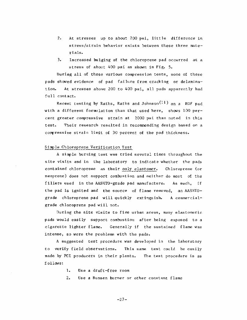
Sample .1 is shown in Fig. 14 after two seconds out of the flame
and the flame has extinguished.
These tests show that the simple flame test should be a use
ful tool for preliminary verification of AASHTO-grade chloroprene
pads and that spectrophotometer analysis is a valid method for
more certain verification.
Shear Tests
A limited number of shear tests were made. A diagram and
photograph of the test set-up are shown in Figs. 15 and 16.
These four tests were set-up to attempt to emulate field condi
tions for pads and not necessarily to maximize the accurate meas
urement of the static friction coefficient of the material. It
-28-

Fig. 11 - Pad sample he1d in Bunsen burner flame
Fig. 12 - Pad burning out of flame
-29-

•
I
- Jl)-
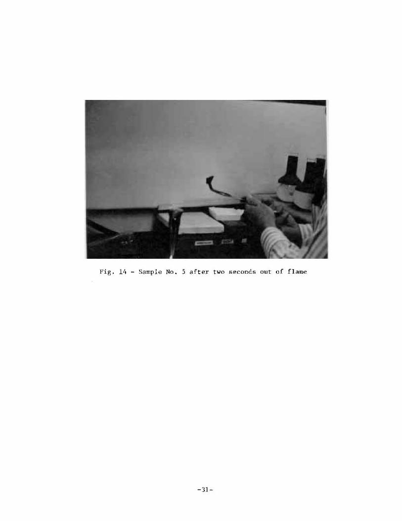
Fig. 14 - Sample No.5 after two seconds out of flame
-31-

STEEl~-_ BEAR I NG It' ---"Ir--"
p
2 IDENTICAL 3/S"X5"X5" PAD SPECIMENS
=:2===:J-- s /
(BY HYDRAULIC JACK WITH LOAD CELL)
P (BY TEST I NG MACH I NE)
Fig. 15 - Diagram of shear test setup
-32-

Fig. 16 - Photograph of shear test
-33-

was decided to test for shear properties under approximately max
i~lrn compression shear loading conditions. Mill quality steel
bearing surfaces, free of heavy rust, were used and the pads were
not glued to the steel surfaces. It should be emphasb:ed that
all results relate to an apparent shear and friction performance
that one might expect from pads of these materials and si~e act-
iog on steel bearing surfaces under the conditions noted. These
data do not represent a true material shear modulus, or coeffi
cient of friction obtained under ideal laboratory conditions.
Identical pad specimens,S in. x 5 in. x 3/8 in., were used.
The results are reported in terms of shear stress, i.e. horizon
tal force divided by the undeformed pad area, and shear strain,
i.e. horizontal displacement divided by original pad thickness.
Each test required about 10 to 15 minutes.
The normal compression stresses were 800 psi for chloro-
prene, 1500 psi for ROF and 2000 psi for DLR. These stress
levels are generally equal to the maxill1lm design
la..red. Test results are shown in Figs. 17 and 18.
prene test resul t is not plotted because of
stresses a1-
The ch loro
slipping. early
S lipping of the
shear stress of
chloroprene pads occurred at an extremely low
about 27 psi which is approximately a shear
stress to compressive stress ratio of 0.03. The two tests with
ROF pads showed slippage at shear stresses of about 75 psi and
125 psi, which are at shear to compression stress ratios of O.O~
to 0.08. The ROF pads exhibit a shear modulus of elasticity (G)
of about 700 psi up to a shear stress of 75 psi. At higher
stresses, the shear modulus reduced to about 50 percent of the
original.
The duck layered reinforced (DLR) pad test showed
ent slippage up to the maxi!Tum applied shear stress of
while under a normal compression stress of 2000 psi.
strain of the pad at a shear stress of 200 psi was about
no appar-
200 psi
The shear
10 per-
cent. The DLR pads exhibited an initial shear modulus of elasti
city (G) of about 4700 psi and a secant modulus from 0 to 170 psi
of about 3000 psi.
-34-

'" Q.
CJl CJl W ct: t;;
ct: <I W I CJl
175
150
125
100
75
SHEAR TESTS 2 a 3 -2 ROF Pads- 5x5x3/B All bearing surfaces steel Load in shear at about 10 psi per minute Vertica I Compressive Stress - 1500 psi
o • TEST 2 x • TEST 3
(Both with identical conditions) Slip In TEST 3
x ___ """""
. , , /
I
k--G = 350 psi
50 x I
25
o
. , I
,"""--G :; 700 psi ? I
0.1 0.2 03 0.4
SHEAR STRAIN, (in/in)
0.5 0.6
Fig. 17 - Shear test data on random oriented fiber pads
-35-

200
175
150
'" D. 125 Cf) Cf) w 0:: f- 100 Cf)
0:: .q w :r:
75 Cf)
50
25
/ G = 4700 psi----./ /
I
/ I /,
/ '/
/ I , ,
/
/ I /
/ I /
/ / /
/
/ I I
I I
/
I"'--G = 3000 psi
r
/1/ // j /
.I I
/
o
I I
/ I
I
0.02 0.04 0.06
SHEAR TEST 4-2 Duck Loyer Reinforced Pads -5x5x3/8in.
Vertical Compressive Stress = 2000 psi
Loaded in she or ot 10 psi per minute All Beaflng Surfaces steel
ODS 0.10 0.12
SHEAR STRAIN, (in/in)
Fig. H~ - Shear tcsl data on duck layer reinforced pads

These limited shear-compression tests show that the measHred
friction coefficients (at slippage) for the chloroprene and ROF
pads on steel plate Were only 3 to 8 percent of the applied com
pressive stress.
Creep Tests
The creep tests were made in standard creep frames in a con
trolled temperature ilnd relative humidity room (73Op, 50% R.H.)
as shown in Fig. 19. Six creep tests were made on two samples of
each of the three materials. All tests were on nominal 1/2 in.
thick pads. As shOWn in Fig. 19, the steel plates extended over
the sides of the pads. During testing the separation of the four
corners of these projectin~ steel plates was measured with a mi
crometer and averaged to indicate the initial vertical deforma
tion of the pad during loading and the subsequent time-dependent
creep deformation of the pad for over 120 days While under con-
stant loading. The vertical deformations were measured i;nmedi-
ately after the initial loading, after 4 hours under load, and
then at appropriate intervals during the test peri ad. Again,
maxillUm comp r!::'ss i ve !-l t re!-lses were us ed. The test result" are
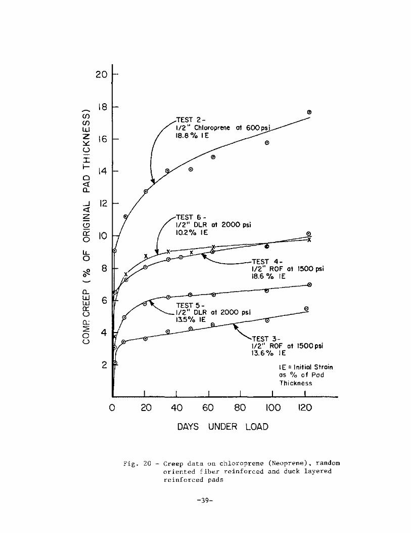
presented in Fig. 20. Discussion of test results follow.
Chloroprene Haterial - The chloroprenc sample No. 2 was
loaded to 600 psi uniform compressive stress. The averar,e meas
ured modulus of elasticity was about 3000 psi. The measured ini
tial and creep strains with pad No.2 were 18.8 and 17.6 percent
of the original pad thickness as shown in Fig. 20. As a result,
the total deformation was 36.4 per-cent of the pad thickness or
0.18 inches. Thus, the 0.5 inch thick pad reduced in thickness
down to 0.32 inches in 120 days. The shape of the creep curve in
Fig. 20 suggests that additional creep shortening will occur in
the future. These data show that at a stress of 600 psi the
creep shortening may equal or exceed the instantaneous shorten
ing.
-37-

Fig. 19 - Typical creep specimen with chloroprene pad at 600 psi
-38-
20
~ 18
(f) (f)
W Z 16 ~ u -I f- 14 0 « 0-
-l 12 « z <!J a:: 10 0
LL 0
~ 8 0 -0-W 6 W a:: U a. ::;; 4 0 U
2
0
.. TEST 2-1/2 II Cl1loroprene IS.S% IE
.,
TEST 6-1/2" DLR at 2000 psi 10.2% IE e
X .. x
TEST 4-1/2" ROF at 1500 psi 18.6 % IE
TEST 5- e 1/2" OLR at 2000 psi 13.5% IE
TEST 3-112" ROF at 1500 psi 13.6 % IE
IE = Initial Strain as % of Pad Thickness
20 40 60 80 100 120
DAYS UNDER LOAD
Fig. 20 - Creep data on chloroprene (Neoprene). random oriented fiber reinforced and duck layered reinforced pads
-39-

Chloraprene test pad No. 1 was preloaded to 800 psi for two
minutes and then unloaded down to 600 psi and held at 600 psi for
the duration of the testing. Results of testing of pad :-la. 1
were not conclusive and are not plotted. Creep was approximately
2 percent of original pad thickness.
The chloroprcne pads showed significant bulging at 600 psi
as shown in Fig. 19 and even more severe bulging at 800 psi. Ex
tension outside the loading plates was not considered significant
in the reported specimens.
Random Oriented Fi ber Material - The ROF pads were loaded to
1500 psi. The average modulus of elasticity measured during the
initial loading was about 9000 psi. The measured average initial
and creep strains were 16.1 and 7.8 percent of the original pad
thickness as shown in Fig. 20. As a result, the total deforma
t ion was 23.9 percent of the pad thickness or 0.12 inches. The
O.S inch thick pad reduced in thickness to 0.38 inches in 120
days. The shape of the creep curves suggest that the continuing
rate of creep and amount of creep are significantly less than
that of the chloroprene pad No. 2 even though the applied stress
on the ROF pad is 2 1/2 times greater.
Duck Layered Reinforced Material - The DLR pads were loaded
to 2000 psi. The average measured modulus of elasticity during
the initial loading was about 17,000 psi. The measured average
initial and creep strains were 11.9 and 8.4 perceflt of the orig
inal pad thickness as shown in Fig. 20. As a result, the total
deformation was 20.3 percent of the pad thickness or 0.10 inches.
Thus, this 0.5 inch thick pad reduced in thickness down to 0.40
inches in 120 days. The shape of the creep curves suggest that
the DLR pads exhibit the least rate of creep of all three materi
als at age 120 days.
These limited testl:; at maxinlJm design stresses illustrate
that additional creep tests are required to better understand
these various engineering factors.
-40-

DISCUSSION
General
There is a need for si~le, straightforward design criteria
for chloroprenc, random oriented fiber and duck layer reinforced
pads for building construction. The present PCl bearing pad de-
sign criteria are widely used, and these criteria appear to pro
vide adequate field performance when proper bearing pad materials
are used. Some pad problems have occurred and often can be re-
lated to poor materials. The remainder of this section deals with
conclusions and observations obtained during this study.
Current Recommendations on Compression of Chloroprenc Bridge
Bearing Pads
The recent publications by Stanton and Roeder(S,6,7) intro
duce a simple formula limiting nominal compressive stress for
plain chloroprene pads, fc' to:
GS -' B
but less than 800 psi for non-restrained,
p lain pads
G Shear Modulus, psi
S = Shape Factor
S Haterial Factor ("'- 1.8)
This formula is straightforward, but it does depend on the
shear modulus of the material. While this is an important physi
cal property of the material, it is not information that is com-
monly available. In addition, this property is difficult to
measure consistently, and it varies widely with temperature.
This proposed forIll.1la esselltially linearizes the allowable com-
pressive stress as a function of shape factor. The simplifica-
tion provided by this type of fOrlrula makes it appealing. Fur-
ther, pad properties are not as accurately known as many other
engineering materials properties and such a simple linear formula
is probably as ac.curate as the present state of our knowledge
warrants.
The material factor of I. 8 i~ applied slightly differently
in the recent DuPont publication(12) and European codes (Table
-4\-

4
0:: 0 3 I-U
Ll w D- 2 <t I (f)
NCHRP 248(5) with ~ - 1.8 on Camp. stress -_-..~,
/
o 200
~
~ i
/ /
400
/ ./
600 800
MAXIMUM COMP. STRESS (psi)
1000
Fig_ 21 - Recent design recommendations for plain chloroprene pads
-43-
From DuPont (12) with Fl - 1.8 on Shope Foctor
Original Curves from PCI, Ed.2

3. As shown in Fig. 6, the stress-strain characteristic
may be influenced by the type of bearing materials
that contact the pad (i.e., concrete vs steel).
4. The compression te~ting with nonparallel plates as
undertaken in this study (Figs. 6, 7 and 8) clearly
illustrated an increased compressive strain when
compared to parallel steel plates.
The review of information on ROF and DLR pads finds limited
data availahle for their design or specification. The lack of
definitive specifications for ROF is a detriment to their use.
However, many producers are using the ROF pads which are less ex
pensive and take higher compressive loads than plain pads.
The design of a bearing pad must relate to the loaded area.
It was noted in the site inspections that many pads were used
that extend some distance outside of the loaded area. The over
sized pad is commonly used to allow holding the pad while the
precast member is being placed.
loaded area.
Design should consider only the
The lateral flow of a pad as illustrated in Fig. 19 is det-
rimental to its bearing capacity. Bonding the pad to the bearing
surfaces, or between reinforcing steel plates. as in the lami
nated steel plate reinforced bearing, is beneficia1. Both
NCHRP 248 and Dupont suggest much higher allowable compressive
stresses for these conditions. Such confined pads are not pres-
ently used in building construction but may be a future develop
ment worth study.
The large vertical displacement caused by the lateral flow
of the chloroprene is one of its best and yet most troublesome
properties. The flow allows accommodation for large irregulari-
ties and shears or rotations in the bearing surfaces. The pres-
cnt PCI and AASH:TO pad design procedures call for a limit on pad
compressive strains. Based on the variations discussed above,
this is not a consistent approach; the use of a design procedure
based on limiting stresses seems more consistent.
-44-

3. As shown in Fig. 6, the stress-strain chBracteristic
may be inf luenced by the type of bearing materials
that contact the pad (i. e •• concrete vs steel).
4. The compression testing with nonparallel plates as
undertaken in this study (Figs. 6. 7 and 8) clearly
illustrated an increased compressive strain when
compared to parallel steel plates.
The review of information on ROF and DLR pads finds limited
data available for their design or specification. The lack of
definitive specifications for ROF is a detriment to their use.
However. many producers are using the ROF pads which are less ex
pensive and take higher compressive loads than plain pads.
The design of a bearing pad must relate to the loaded area.
It was noted in the site inspections that many pads were used
that extend some distance outside of the loaded area. The over
sized pad is commonly used to allow holding the pad while the
precast member is being placed. Design should consider only the
loaded area.
The lateral flow of a pad as illustrated in Fig. 19 is det
rimental to its bearing capacity. Bonding the pad to the bearing
surfaces. or between reinforcing steel plates, as in the lami
nated steel plate reinforced bearing. is beneficial. Both
NCHRP 248 and Dupont suggest much higher allowable compressive
stresses for these conditions. Such confined pads are not pres-
eutly used in building construction but may be a future develop
ment worth study.
the large vertical displacement caused by the lateral flow
of the chloroprene is one of its best and yet most troublesome
properties. The flow allows accommodation for large irregulari-
ties and shears or rotations in the bearing surfaces. The preS-
ent PCI and AASH:TO pad des ign procedures call for a limit on pad
compressive strains. Based on the variations discussed above,
this is not a consistent approach; the use of a design procedure
based on limiting stresses seems more consistent.
-44-

Rotation aod Shear Deformations
Thc consideration of rotation, i. e.. nonparallel bearing
surfaces is not made in either the PCI or AASHTO design proC',e
durcs. A common rule of thumb(3) has been to limit such rotation
to:
r = .2.<!c L
de compression displacement
L = length of hearing in direction of rotation
r = rnaxilTUlID rotati on in radians
This is intended to prevent lift-off at the low-stress end of the
nonparallel plates. This geometry is illustrated in Fig. 22.
Lateral shear displacement has also commonly been limited to
0.5 of the pad thickness as illustrated in Fig. 23.
practice has allowed up to 0.7.
European
It is actually the combination of compressive strain, shear
strain and rotation strain that leads to failure (cracking) in
the critical toe region of the bearing pad. The present limits
on rotation and shear deformation were set to be sufficiently
conservative so that design compression stresses are not signifi-
cantly affected by deformations within the limits. The European
Codes (Table 1) attempt to model these combinations, either
through stress or strain limitations. However, the resulting ex
pressions are often complex and the wide variety of properties
for pads used in the U.S. negate the usefulness of such detailed
analysis. Also, as discussed belCYW. slippage probably makes such
limits physically unrealistic.
Friction and Slippage
Design for the shear deformation of elastomeric pads as out
lined above has generally been based upon the assumption that the
horizontally loaded pads can deform in shear to 50 percent of the
pad thickness while under perpendicular design compressive stres
ses and that friction will prevent the pad from slipping. The
-45-

( de = COMPRESSION
'i=r==. ~~~= DISPLACEMENT
PAD
~r ~ J -_:'d //
*-... L
Fig. 22 - Limitation on rotation
\ r = ROTATION
MAXIMUM = 2dc L
/ds~ t/2 FOR
~K CHLOROPRENE i I
t~_~/~I~~~~~~~~!~ --1
Fig. 23 - Shear movement limits
-46-

upper limit on the frictional force which could he developed be
tween elastooeric pads and steel or concrete surfaces was assumed
to be 0.7 of the normal force, based upon static friction coef
ficient test data.
The 1982 NCHKP 248 report(5) discusses the apparently trou
blesome slipping characteristic of plain elastomeric pads when
loaded in shear while under perpendicular compression load",.
This slipping or "walking out from under loads" is a commonly
noted pad problem. The NCHRP report discusses research reported
in Europe in 1965 which showed that the friction coefficient for
concrete or steel surfaces in contact with plain rubber pads de
creased dramatically as the compressive stress level on the
rubber pad was increased. This European study suggested the fol
lowing equation for a conservative estimate of the coefficient of
friction for concrete or steel surfaces as a function of compres
sive stress on the pad:
where
11)0.10+ 29
DC
friction coefficient ~ as
a c
0c compressive stress on pad. psi
as = shear stress on pad, psi
A plot of this equation is shown in Fig. 24 covering a range in
compressive stress from SO to 2,000 psi. It is noted that the
value approaches 0.7 at compressive stress levels of SO psi while
it decreases rapidly to values of only 0.17 to 0.12 for compres
sive stress levels of 400 psi to 2,000 ~si. respectively.
A similar reduction effect on 11 for teflon pads is shown in
the PCL Architectural Design Manual(3) in Fig. 2.81. The frir
tion coefficient for TFE reduces from about 0.09 to 0.04 as the
compressive stress level increases from 10 to 2,000 psi.
These dramatic decreases in friction coefficients have not
been previously accounted for in df''''"!.s'-' practice. The NCHRP 248
report discusses other test data which substantiate this decrease
-47-

--l ct U -f-a: l.LJ >
0.7
o 0.6 f-
en f3::i.. a: • 0.5 f-en enf3
a: a:f-ct en 0.4 l.LJ :I:l.LJ en>
en ~~ 0.3 ~a: ZCl... O~ NO -u a: 0.2 o :I:
IL. o 0.1
o -~ a: 0
o 400 800
UIC 772 EQUATION
RUBBER PADS ON CONCRETE OR STEEL SURFACES
1200 1600 2000
COMPRESSIVE STRESS ON PAD, Cle , psi
Fig. 24 - Friction coefficient versus normal stress for rubber pads
-48-

and certain comments taken directly from this report are as fol
lows:
''Friction is thus seen to be imperfectly under-
stood and the possibility of slipping merits con-
servative consideration."
''Further, the unreliability of the friction results
in the increased probability of a plain pad 'walk
i ng' f rom under the load."
"The lower values of Jl found by others, combined
with the effects of dynamic live load which further
reduce them, make some slip almost inevitable for
pads of practical shape factors."
A significant research paper on this subject is from West
Germany and was published in A.C.l. Publication SP-70(l4) in
1981. This paper by I. Schrage presented and discussed numerous
tests on plain chloroprene pads undergoing shear/compression
tests against concrete and steel surfaces. The tests utilized
nominal compressive stresses of 72, 725 and 2,900 psi on the
plain chloroprene pads. The pad shape factor was generally 2. O.
These tests applied the shear loads at constant horizontal dis
placement rates of 1.97 in. /sec, O. 02 in. /sec and O. 0004 in. /sec.
to a maximum displacement of 0.7, 1.4 and 2.1 times the pad
thickness.
The typical unrestrained displacement rate for the end of a
60 ft long double-tee member experiencing a SO"F temperature
change uniformly over a six hour period would be about 0.000005
in. /sec at each end of the tee. Thus, the lowest rate of shear
loading used in these tests (0.0004 in./sec) was most typical of
daily temperature effects and long-term creep and shrinkage ef-
f ects.
Their data are presented and discussed in terms of "slip re
sistance" at the different maximum shear deformations for the
pad. The German building regulations assume that nonanchored
bearings are appropriate to transfer short-term tangential loads.
-49-

However, service performancE>_ is limited to a maxirrum shear defor
mati on for the pad of 0.7 times the pad thickness and the fric
tion coefficient, jJ. was previously assumed at 0.20.
Si~nificant observations and conclusions from these test~
arc as follows:
Minor slip occurs at even low shear stresses.
Plain chloroprene pads under low vertical stresses
tend to move under horizontal load by pure slip-
page.
Plain chloroprene pads exhibit "rolling" and slip
ping when under high compressive stresses and sub
jected to horizontal shear loads.
The coefficient of friction is dependent on the
shear loading rate.
For the very slow shear loading rate, the tests on
steel and concrete surfaces produced different co-
efficients of friction.
Figures 25 and 26 show the average relationship between .. -
and compressive stress on the pad at a "shear plus slippage"
strain of 70 percent llsing concrete and steel surfaces. Figure
27 shows the range of the data for their rrultiple tests on chlor
oprene pads on concrete surfaces using the shear load rate of
0.02 in./sec.
In the C'_onclusion portion of his 1981 ACI paper, Mr. Schrage
suggests a "rough" equation for relating friction dependence on
compressive stress as follows:
~ 0.05 + 58 Gc
He further comments that the present German regulation of
using -I' '" 0.20 is realistic at very low cOflllressive stresses but
the pad will slip before reaching shear strAins of 70 percent.
-50-

0.6
0.5
0.4
0.3
0.2
0.1
o o
~ \
\~ \ \
FROM REFERENCE 14 CHLOROPRENE PADS ON CONCRETE SURFACES
SHEAR LOADING RATE
\ \ \ V L97 "/SeC.
\ ' \" O.02"/~ _________
00:;;';-r - _=~_:::---------.--.:::::::::::=:: - ----~ 500 1000 1500 2000 2500 3000
COMPRESSIVE STRESS ON PAD, ere' psi
Fig. 25 - Compressive stress versus apparent friction factor - concrete surfaces
-51-

-'z «- 0.7 <..>« _0: 1-1-0:(1) W >a.
0.6 -' 0(1)
I-0
(l)Z (1)« 0.5 W 0:0: 1-« (I) W ::!.. a:: m ; 0.4
« "" WI- 0 I «I'-(I)
0.3
0.2
0.1
~ \
\
\ \
"-
FROM REFERENCE 14 CHLOROPRENE PADS ON STEEL SURFACES
SHEAR LOADING RATE
1.97 "/sec.
'\ 0.02 ·I,ec.~
-\, -------
'- -'- 0.0004 "I ,ec. ~ :::::---.. -- ..... ---- --------OL-__ __' ____ -L ____ ~ ____ ~ __ __'~ __ ~
o 500 1000 1500 2000 2500 3000
COMPRESSIVE STRESS ON PAD.O(;, psi
Fig. 26 - Compressive stress versus apparent friction factor - steel surfaces
-52-

-I;;:; «« uO: I-ti; 0: w >0..
-I OC/l I-
o C/lZ C/l« w 0:0:
0.7
0.6
0.5
1-« C/l ~ ::1. 0.4 0: C/l -« :o.e w 0 :r:!;io C/l I'-
0.3
o 500 1000
FROM REFERENCE 14 CHLOROPRENE PADS ON CONCRETE SURFACES " SHEAR LOADING RATE, 0.02 Isec.
RANGE OF DATA
1500 2000 2500 3000
COMPRESSIVE STRESS ON PAD, CT C ' psi
Fig. 27 - Range of data - concrete surfaces
-53-

He also pointed out that at high compressive stresses, the ~
value will be well below 0.20. Figure 28 shows the above sug-
gested equation and compares it with the 1965 UIC equation previ
ously discussed.
A study of the shear-compression strength of specially form
ulated random oriented fiber pads was undertaken in 1983-84 by a
pad manufacturer in the United State5(I1). This data was submit-
ted during this study for review. Sixteen shear tests were made
using pads ranging in size from 2 x 2 to 6 x 6 in. (square pads)
and 1-1/2 x 3 to 3 x 6 in. (rectangular pads). The thicknesses
were 1/4, 1/2 and 3/4 in. The compressive stress levels used
Were 800 psi
used by WJE
and 1,200 psi. The shear test method is the same as
as shown in Fig. 15. These tests were on uniform
Significant test results from float finished concrete surfaces.
this U.S. study are discussed below:
The ROF pad static friction coefficient on a con
crete surface using only gravity loading during an
inclined plane test, where the angle of the in
clined plane was measured at which sliding or slip
ping initiated, varied from 0.7 to 0.9. While the
0.7 value was the most usual.
The friction coefficient measured during the 16
shear-compression tests varied from 0.2 to 0.5, de
pending upon the compression stress and shear dis
placement.
The leading edge of the pad tended to roll at shear
plus slip deformations of about 3/4 of the pad
thickness. (This same type of behavior was noted
in the tests by Schrage on chloroprene pads with
similar geometries.)
For compressive stress levels of 800 psi and
1,200 psi on the ROF pads, the average friction co
efficient was about 0.20 and 0.15, at shear plus
slippage strains of 75 percent. These coefficients
gradually increased to about 0.30 and 0.27. at
-54-

· .J:.!! <0 u O -I'-f-0:: w,,->0
02 f--< en 0:: enf-wen 0::0:: f-< en W o:::r: <{en w :i. :r:f-en<{
.Jen ~[3 20:: Of-Nen 0:: Ow :r:::: ,,-en oen w 00:: _a.. f-::;: <0 o::u
0.7
0.6
I I
0.5 I I \
0.4 \ \ \
0.3 \ \ \
0.2 \ _ il-'- ~ 0.10 + 29/cre (965) ~
"- -------0.1
I-'- ~ 0.05 + 58/cre
( 1981)
0 0 500 1000 1500 2000 2500
COMPRESSIVE STRESS ON PAD, eTc. psi
Fig. 28 - Comparison of friction coefficients from 1965 and 1981 West German reports
-55-
3000

shear plus slippage displacements of twice the pad
thickness. At that time significant slippage had
occurred.
These recently acquired shear test data on ROF pads on con
crete are shown in Fig. 29 superimposed on the I. Schrage results
for chloroprene on concrete.
The previously discussed WJE shear-compression tests on
chloroprene and ROF pads on steel surfaces exhibited extremely
low friction coefficients. These tests used a shear loading rate
of about 0.00002 in. /sec. which is slower than the lowest rate
used in the Schrage tests on chloroprene. The chloroprene pad
test for PCl utilized a compressive stress of 800 psi and slip
occurred at a friction coefficient of approximately 0.03 at a
very low shear strain. The ROF on steel tests both utilized a
compressive stress of 1500 psi and friction coefficients 0.05 and
0.08 resulted. These data are plotted in Fig. 30 which also
shows the Schrage data for chloroprene pads on steel surfaceS for
comparison.
Fig. 31 shows the 1965 UIC equation and the 1981 equation
proposed by Schrage for rubber or chloroprene pads on either con
crete or steel surfaces and all the 1984 U.S. test results for
both ROF and chloroprene pads.
The DLR pad test for PCl did not show any apparent slippage
while being subjected to a shear stress of 200 psi and under a
compressive stress of 2, 000 psi. The shear strain was only 10
percent and the friction coefficient, ~,at the end of the test
was about 0.10.
city.
This test was terminated due to equipment capa-
These 20 shear-compression tests in the U.S.
substantiate the European data and show that
during 1983-84
the shear-
compression friction coefficients for chloroprene and the spe
cially formulated and standard ROF pads decrease well below a
static coefficient of 0.7 that is commonly used in design, under
commonly used compression loads.
-56-

0.7
0.6
0.5
0.4
0.3
0.2
0.1
o o 400
... ROF PADS - CONCRETE SURFACES USA DATA REF (II)
CHLOROPRENE PADS - CONCRETE SURFACES 1981 GERMAN DATA BY I. SCHRAGE (14)
800 1200 1600
LOAD RATE
1.97'/sec_
0.0004 ''Isec.
2000
COMPRESSIVE STRESS ON PAD, eTC, psi
Fig. 29 - Compressive stress versus friction for ROY and chloroprene on concrete surfaces
-57-

0.7
0.6
UlO:: [fJ L5 0.5 0:: I f-Ul Ul
o 0:: ~ :::L 0.4 «0 ILl"" •
0.. I~_ Ul~...J
« Ul 0.3 ...J «Ul f-[fJ Zo:: Of-t:! Ul 0.2 0:: o I ILl
> ,,-iii O[fJ
off 0.1
•
• CHLOROPRENE PAD ON STEEL. 1984 WJE DATA
... ROF PADS ON STEEL, 1984 WJE DATA
CHLOROPRENE PADS· STEEL SURFACES 1981 GERMAN DATA BY I. SCHRAGE (14)
...
...
LOAD RATE
1.97 -, sec.
Q,Q2"/sec.
0.0004 ''/ sec . ~~ 0::<"> o ~----~----~----~----~--~
o 400 800 1200 1600 2000
COMPRESSIVE STRESS, psi
Fig. 30 - Stress ratios on steel surfaces
-58-

0.7
0.6
0.5
04
03
0.2
0.1
I \ I I \ \ \ \
At. 1984 TESTS ON ROF PADS ON CONCRETE REF (II)
• 1984 TEST ON ROF PADS ON STEEL-WJE \
\ \ \ ~
• 1984 TEST ON CHLOROPRENE ON STEEL-WJE
~ fl-': 0.10 + 29/o-C (1965) (UIC)
---------1-'" 0.05 + 58/o-
C (1981)
(REF 14). • OL-_--' __ -.l.. __ -J-__ -'-_--'
o 400 800 1200 1600 2000
COMPRESSIVE STRESS ON PAD, ()c • psi
Fig. 31 - Comparison of friction coefficient from 1965 and 1981 West German reports and U.S. test results
-59-

While the shear-compression friction coefficient, \l, at
slippage or pad rolling decreases dramatically as the compressive
stress level increases, the available or allowable shear stress
on the pad under the same conditions does not decrease. The data
from the 24 European tests and the 20 U.S. tests on plain pads
were calculated and plotted in Fig. 32 to compare the shear
stress on the pad versus compressive stress on the pad at shear
plus slippage strains of 70 percent. These plots are for chloro-
prene and ROF pads on concrete or steel surfaces. These four
curves show increasing shear stress capacity as compressive
stress increases. These curves are based on a slow loading rate,
such as occurs due to temperature changes, and are not appropri
ate for seismic loading.
The European equations for \l are of the form:
IJ=A +8
0 0
where A and B Constants
as shear stress on pad
a c • compressive stress on
" = friction coefficient
This equation is equivalent to
A + ~
° C O"c
os'" A 0c + B
or
pad
(os/cc)
This linear equation with an intercept on the shear stress
axis can then be used to approximate the curves in Fig. 32 and
can be solved for the A and B constants.
these constants are as follows:
Pad TlEe Surface A
Chloroprene Steel 0.03
Chloroprene Concrete 0.04
ROF Steel 0.05
ROF Concrete 0.09
-60-
Approximate values for
B
14
38
36
90

I- '" <t Cl.
-• 0<1" <to ,,-"-
"-Z 0 0 Z en <t en cr W I-0: en I-en W
l.?
0: ~ <t"-W-IuJ en
O Z <t cr <t W I en
210
ROF ON CONCRETE
180
150
120
ON STEEL ROF
90
60
30
0
ON CONCRETE
CHLOROPRENE
0 400 800 1200 1600 2000
COMPRESSIVE STRESS ON PAD, eTc , psi
Fig. 32 - Shear stress versus compressive stress for chloroprene (Neoprene) and random oriented fiber pads on steel and concrete surfaces
-6J.-

These constants would produce equations for "fJ as follows for the
above four combinations:
" 0.03 + 14/ 0 c (Chloroprene Steel)
" 0.04 + 38/ 0 c (Ch lorop rene Concrete)
" 0.05 + 36/ oc (ROF Steel)
" 0.09 + 90/° c (ROF Concrete)
The form of this equation suggests that the allowable shear
stress at slippage increases linearly as the compressive stress
increases. Considering Fig. 32, it can be noted that when the
linearity ceases, it is probably evidence of unnoticed slippage
during the testing. The constants suggest that only 3 to 9 psi
added shear stress is achieved for each 100 psi added compressive
stress on the pad.
The above four equations are shown plotted in Fig. 33 along
with the 1981 German equation suggested by Schrage for chloro-
prene on steel or concrete surfaces.
Creep Characteristics
The creep testing indicated that the creep strains after 120
days of loading ranged from 48 to 94 percent of the initial
shortening and averaged 70 percent for these three materials.
These values are lIuch greater than the 20 to 40 percent values
discussed in the NCHRP 248 report based on large size bridge
bearings. They are also IIllch greater than the creep values shown
in the 1983 DuPont brochure on chloroprene. These creep tests on
small pads were undertaken using maxinum design compressive
stresses and for a reasonably long period and certainly represent
rigorous conditions although nonparallel plates were not in-
eluded. The additional vertical deflection of the pad from the
creep in the bearing pads probably has little effect in the
building. It might have to be accounted for in certain joint de
tails, but the majority of the pad deflection has often occurred
by the time the toppings are cast and connections are made.
-62-

::l.. lLJ ...J m ~ 0 ...J ...J <t
lLJ
~ ::;; X 0 cr: 0. 0. <t
0.7
I I
0.6 \
--- 1981 GERMAN EQUATION-CHLOROPRENE ON
\ STEEL OR CONCRETE (REFERENCE 14)
0.5 \ \ \
0.4 \ \
0.3 \ \ \
0.2 '\. "- ROF CONCRETE
"- ---0.1 ---- --- - ----ROF STEEL CHLOROPRENE STEEL CHLOROPRENE
CONCRETE
0 0 400 800 1200 1600 2000
COMPRESSIVE STRESS ON PAD, eTC' psi
Fig. 33 - Friction coefficient variation for chloroprcnc (Neoprene) and random or ie_nted pads on ('_oncrE-_te and !'iteel surfaces
-61-
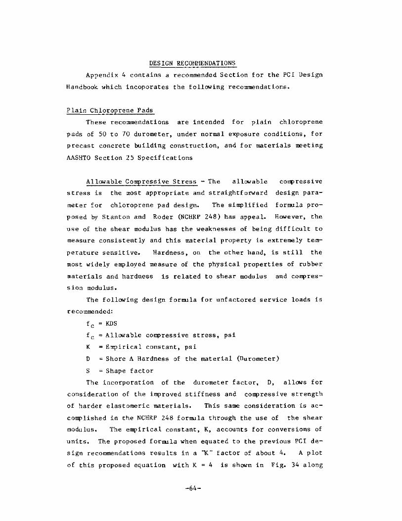
DES IGN RECQHllENDATIONS
Appendix 4 contains a recommended Section for the pcr Design
Handbook which incoporates the following recommendations.
Plain Chloroprene Pads
These recommendations are intended for plain chloroprene
pads of 50 to 70 durometer, under normal exposure conditions, for
precast concrete building construction, and for materials meeting
AA$HTO Section 25 Specifications
Allowable COmpressive Stress - The allowable COIIl' ress i ve
stress is the most appropriate and straightforward design para
meter for chloroprene pad design. The simplified formula pro
posed by Stanton aod Roder (NCHRP 248) has appeal. However, the
use of the shear modulus has the weaknesses of being difficult to
measure consistently and this material property is extremely tem-
perature sensitive. Hardness, on the other hand, is still the
most widely employed measure of the physical properties of rubber
materials and hardness is related to shear modulus and compres
sion modulus.
The follOWing design formula for unfactored service loads is
recommended:
fc KDS
fc : Allowable compressive stress, psi
K : Empirical constant, psi
D Shore A Hardness of the material (Durometer)
S Shape factor
The incorporation of the durometer factor, 0, allows for
consideration of the improved stiffness and compressive strength
of harder elastomeric materials. This same consideration is ac-
complished in the NCHRP 248 formula through the use of the shear
modulus. The empirical constant, K, accounts for conversions of
units. The proposed formula when equated to the previous PCl de-
sign recommendations results in a '1(" factor of about 4. A plot
of this proposed equation with K = 4 is shown in Fig. 34 along
-64-

4
3 a: 0 I-U
it 2
w Q.. <l :r: CIl
NCHRP 24B (5) with fl = I.B on Camp. stress
/
6
/ §/ if
Q/ &;
, /
o 200 400 600 BOO
MAXIMUM COMP. STRESS (psi)
1000
From Dupont with fl = I.B on Shope Factor (Extrapolated beyond 10 percent max. strain)
Proposed Formula with K = 4
Original Curves from PCI, Ed. 2
Fig. 34 - Recent design recommendations for chloroprene (Neoprene_) pads compared with PCl and recommended formula
-65-

with the present PCI recommendations and the NCHRP 248 bridge pad
recommendations which were given in Fig. 21. The proposed formu
la matches closelY with the current PCI recommendations and is
considerbLy less conservative than either of the recent bridge
recommendations for plain pads. This is appropriate since the
present PCI recommendations are considered well tested and most
of the problems encountered in the field were clearly related to
poor materials.
Since plain pads do not contain any reinforcing. the elasto
mer itself must resist internal tensile stresses from bulging
cauBed by the compression loading. Friction along the loaded
surfaces aL!;o acts to restrain bulging. Since the friction coef
ficient at moderate to high compression stresses is very low and
potentially unreliable due to long-term creep effects, plain
chloroprene pads should be designed for relatively low compres
sive sresses, particularly under unfactored working dead loads.
A 1,000 psi maximum design compressive stress for unfactored
design loads has been used for many years. However, the results
of the testing in this project illustrate that significant bulg
ing and creep deformation occur when high compressive stresses
(Le., 600 psi) are held constant for long periods. it is recon!""""
mended that the maximum design compressive stress under unfactor
ed dead and Live loads be generally limited to 800 psi and that
the unfactored sustained dead load stress be limited to 300 to
500 ps 1.
Further limitations are recommended that under double tee
stem.'::; pads with a shape factor less than 2 he avoided and under
beams a shape factor less than 3 be avoided. This implies that
small, thick pads should not be used. For example, a 1/4 x 2 x
2 in. or a 1/2 x 4 x 4 in. pad have a shape factor (SF) of 2.
Plain chloroprene pads of these sizes that are any thicker should
be used only with extreme care.
required, and if so. reinforced
Such small pads may sometimes be
material is recommended. The
choice of SF = 2 as a limit is based on observed results and
-66-

problems. It is noted that these recommendations are based on
properties for the loaded area of the pad.
Shear Hodulus and Frictional Effects - The shear modulus is
u5ually determined by pad manufacturers using the ASTi1 D4014-81
test procedures. These procedures utilize pads bonded to steel
plates and slipping is not permitted. Since bearing pads in pre
cast building construction are not glued or fixed in place. slip
page occurs, and shear deformation calculations using a shear
modulus are unrealistic, even when a long-term shear modulus of
0.5 G is assumed. The
values of 110, 150 and
use of normal
215 psi(3) for
short-term shear modulus
50, 60 and 70 durometer
chloroprene pads (at 70"F) will significantly underestimate the
measured pad deformation in actual tests.
The recent shear-compression testing discussed in the previ
ous section suggests that pads slip appreciably and that this
slip can play a significant role in redUCing forces transmitted
to the ends of precast members by frictional forces. While the
amount of testing has been limited, the data in the previous sec
tion suggest that Fig. 32 represents an alternative and improved
design aid to estimate frictional forces at ends of members. The
use of the data in Fig. 32 as an upper limi t is conservative
since long-term creep effects are not included.
Shear Deformation and Movement Limitations - Present design
practice has been to limit the shear strain of the pad to 50 per
cent of the pad thickness. This design practice did not totally
recognize the effect of slippage. This limitation results in a
pild thickness of two times the calculated deformation of the end
of the precast member and a resulting low shape factor since
thick pads are often necessary. Current testing and other prac
t ice in European codes leads to the approach of limiting pad
shear and slip to 70 percent of the pad thickness since rolling
and severe slipping is noted at this point. Based upon this
-67-

limit, the pad thickness can be selected as 1.4 times the calcu-
lated deformation of the end of the precast member.
to a more favorable shape factor.
This leads
Rotation - Rotation is not presentLy covered in the PCI pad
design recommendations. Nonparallel bearing surfaces are a com-
man problem and were noted in many instances in the site visits.
A method to consider rotation of bearing surfaces in pad design
procedures by using the follCMing formula is suggested:
Maximum rotation < D.3t
L
t '" pad thickness
L '" dimension of pad
This wOllld be taken in either one of the principal dimensions of
the pad in which the maximum rotation occurs. This formula is
based on the assumption that a minimum compressive displacement
of D.1St occurs under design loads and then applying the rule of
thumb discussed previously:
2(0.15t) = O.3t
L L L
Since nonparallel bearing surfaces do exist, it must be rec
ognized that such nonuniform loading can double the 1S percent
strain often assumed in design. Thus, 3D percent instantaneous
compressive strain can occur in highly stressed, nonparallel sit
uations as was noted in the testing.
Random Fiber Reinforced Pads
Allowable COJJq)ressive Stress - The PCI Design Hanuals previ
ously suggested a maximum design compressive stress of 1,50D psi
for ROF pads. This suggested level of stress was not influenced
by the shape factor.
Few problems were noted in the site inspections, although
limited cracking of the exposed surfaces was observed. As SUCh,
-68-

there is little evidence to suggest significant problems when ROF
is used at or below this stress level.
Since ROF pads have a more limited experience record than
chloroprene pads, and since recent testing(ll) suggests that pad
performance is sensitive to low shape factor, the above recommen
dation may be too liberal for small shape factors and design con
servatism may be warranted. Also, testing has shown that ROF
pads can have widely different compression and shear modulus
values depending on the elastomer type, and fiber type and orien-
tat ion.
sign.
Recognition of shape factor is recommended in their de
Based upon the data available, the follOWing maximum de-
sign compressive stresses are recommended for unfactored dead and
live loads:
Shape Factor
2
3
4
5
)5
Uniform Compressive Stress,
(psi)
llOO
1200
l300
1400
1500
1500
Or stated as a fOTrrula; fc = 1000 + 100(SF) <1500 psi.
The compressibility of ROF pads must be calculated or esti
mated from test data from the actual pad material used since
stiffness of the ROF pads varies significantly from one manufac-
turer to another. As an example. for a S.F. of 2.5, one pad ma-
terial under a uniform compressive stress of 1250 psi compressed
about 1 S percent while a different manufacturer's pad compressed
-69-

about 30 percent. Pads from various manufacturers have been sub
jected to uniform compressive stresses of SOOO psi without exhi
biting any evidence of pad failure, other than large vertical de
formation.
Shear Modulus and Friction - The shear modulus of ROF pads
is higher than chloroprene pads and values in the range o( 300 to
700 psi have been measured at room temperature. High or low tem
perature data are not available.
The shear-compression testing discussed previously has shown
significant slippage and rolling at apparent shear strains of 15
to 7S percent. These tests show similar slippage and rolling be
havior as was noted in the chloroprene tests from Europe which
showed severe slippage and rolling at or near 70 percent apparent
shear strain.
Since pad slippage does occur, it is recommended that the
pad thickness be selected as 1.4 times the calculated deformation
of the end of the precast member, similarly to the chloroprene
recommendation. The maxiTIJ.lm friction force which can be produced
at the ends of members can be estimated by the_ shear stress ver
sus cO!l{lressive stress curves shown in Fig;. 32.
Rotation - The same recommendations ~ould be suggested here
as were used in chloroprene pads. The recommendations are bHsed
on a miniTIJ.lm 15 percent vertical strain in the pad and rotations
limited to avoid lift-off or tension in the high side. These
criteria also seem appropriate for ROF pads.
Duck Layer Reinforced Pads
AllCMablc Compressive Stress - Present pel criteria and a
number of manufacturers suggest an allowable maxinum compressive
stress of 2000 psi for DLR pads. This value appears appropriate
and should be continued in the pel literature. These pads are
seldom used in smaller shape factors and Httle_ apparent need
exists to limit stresses on smaller pads.
-70-

Shear Modulus - The 1'lhear modulus is Truch higher than for
the other pads. A recommended range of shear modulus is suggest
ed with a lower limit of 500 psi, taken from present PCl recom
mendations, and an upper limit of 3000 psi, as noted in our test
ing.
Shear Deformation - The high shear modulus lead"l to very
small shear deformations during shear-compression testing. While
the single test in this research is far from conclu1'live it is re
commended that a limit of O.2t be considered for the maxiIlum
shear deformation. In this single test a shear deformation of
about O.lOt required a shear stress of over 200 psi and no ob-
servable slipping had occurred. This area warrants future test-
ing to confirm upper limits on shear deformation and slippage be
havior.
Rotation - Essentially the same recommendations for rotation
limits would be used as for other pads, based on a miniIIllm verti
cal strain of 0.15 and designing against lift-off or tension on
the high side.
Chloroprene Identification Test
The simple burning test developed in this study apparently
provides a ready means of preliminary identification of those
pads containing only chloroprene as an elastomer. The small pad
is inserted in a Bunsen burner flame for 5 seconds and then with
drawn. If the flame dies in less than 15 to 20 seconds, the pad
is probably composed of chloroprene elastomer. Nore certain
analysi5 can be accomplished using spectrometer analysiS, with
the availability of spectra of various materials to be identi
fied. These spectra tests are Truch more expensive and time con
suming.
-71-

Future ResearC'_h
The general scarcity of test data relating to random orient
ed fiber and duck layer reinforced pads suggests a serious need
for future research with these pad types. and need for definitive
specifications for these materials.
The slipping noted in the shear-compression testing at rnod-
erate to high compressive stress in Europe and the U.S.A. sug-
gests that further testing and correlation with field performance
would perhaps yield a different outlook on the performance of
plain bearing pads. Tests should be undertaken on actual long
span structures to determine if the member deformation results in
pad shear strains, slippage or a combination of these two mecha
nisms.
Further correlation of the '1(" factor in the simplified com
pressive stress formula proposed here for chloroprene pads should
be considered to provide the designer with safe yet economical
designs.
The use of plastic shim material as bearing pads is an in
teresting development that also needs future review, study and
evaluation.
SUHMARY AND CONCLUSIONS
A broad study of elastomeric bearing pads for use in precast
concrete building construction was undertaken. This work includ
ed a survey of PCI producers to identify problems and practices,
and a review of recent literature. Limited laboratory testing on
chloroprene (neoprene). random oriented fiber and duck layer re
inforced elastomeric pads was undertaken with respect to long
term compressive creep, shear-compression, and uniform and nonun
iform compression. Parking structures in five different cities
in various U.S. locations were inspected to determine actual
field performance of bearing pads under out-of-door conditions.
As a result of this work, new design recommendations are
suggested for use in the pel literature. A simple method to
-72-

identify AASHTO-grade ehloroprene (neoprene) pads and a new
method to estimate frietional forces on pads Were developed.
Noteworthy conclusions or observations from these various
tasks are discussed in the following sections:
Surveys aad Site Visits
1. Bearing pad problems exist. but not on a broad
scale.
2. The use of commercial-grade chloroprene pads has
created numerous problems in the past such as ex
cessive bulging, disintegration, etc.
3. Chloroprene, random fi her reinforced and duck layer
reinforced pads are most prevalent in building con
struction.
4. Nonuniform bearing due to nonparallel surfaces is a
commonly noted problem and excessive deformation of
the pad does occur.
5. Mislocated pads were observed. These mislocations
can be caused by improper installation or by grad
ual pad slippage due to low frictional resistance.
6. Pertinent generalized design information based upon
appropriate testing of pads used for building con
struction are not available, particularly for rein
forced pads.
7. AASHTO-grade chloroprene pads exhibited excellent
performance in the field survey. Commercial-grade
chloroprene pads exhibited Widely different perfor
mance in the field from total disintegration to
good performance. A simple hurnability test was
used during this work to help identity if a chloro
prene pad is AASHTO-grade, i.e., if it contains
only chloroprene as the elastomer.
8. Pads which are supposedly deformed in horizontal
shear as assumed in design were not observed in
that deformed shape during the site visits.
-73-

Laboratory Testing
1. The long-term compressive creep testing on chloro
prene pads at 600 psi showed high creep strain of
almost 90 percent of the initial pad strain. This
iR greater than the 30 percent creep strain versus
initial strain data shown in the 1983 DuPont liter
ature for 55 Ourometer material.
2. The creep tests show the beneficial effect of in
ternal reinforcing in the ROF and DLR pads on com
preRsion modulu8, rate of creep, total creep and
total deformation.
3. Extremely lCtW' friction coefficients of from 0.03 to
0.08 times the applied compressive stresses were
measured.
4. Typical tolerances for precast construction lead to
nonparallel bearing surfaces and tests to simulate
this condition shCtW' an increase in the average in
stantaneous compressive strain in the pad by as
much as 100 percent over uniform bearing condi
t ions.
Li.tErature Review-
1. A numher of companies ma.nufacture pads which can be
generical Ly the same but which can have widely dif
ferent engineering properties.
2. NCHRP Report No. 248 suggests a simplified equation
for design of compression strength of plain bearing
pads. This equation uti lizes the shape factor and
shear modulus as variables.
3. The 1983 DuPont brochure '"Engineering Properties of
Neoprene Bridge Bearings" suggests that plain (rlOn
reinforced) chloroprene pads be generally limited
to design compressive stresses of 400 to 500 psi.
-74-

This compares wi.th the prescnt AASHTO design value
of 800 psi for plain, unrestrained chloroprene
bearings.
4. European design utilizes an allowable shear dis
placement of 0.5 to 0.7 times the pad thickness.
Testing has shown that at an apparent shear strain
of 70 percent severe slippage <lnd rolling of the_
pad occurs. The shear-colJ{>ression stress ratio at
slipping may be extremely low (0.2 to 0.05) when
moderate to high compressive stresSes are applied
to chloroprene materials.
5. The use of the traditional shear modulus equation
to estimate the horizontal force the pad can devel
op, even USing the long-term value of 50 percent of
the shear modulus, appears to be inappropriate.
This traditional design approach does not recognize
the slippage that occurs at all levels of shear
stress and the shear modulus values used in these
equations were usually determined from glued pads
which do not reflect realistic field conditions.
An alternative design procedure is suggested.
Re commendat ions
Simp lif ied fornu las for compress ion des ign of c.h loroprene
pads are suggested. A method of considering plate rotation in
bearing pad design is suggested. Revisions in maximum recommend
ed cOIl{lression values for chloroprene are suggested.
Pad thickness de!>ign has been modified to allow thinner pads
with subsequently larger shape fac.tors. generally based upon
1.4 times the anticipated movement of the end of the precast mem
ber. Previous design concepts gencrally utili,zed two times the
end-of-member movement for pad thickness.
A design chart, based on laboratory tests, suggesting re-
vised friction forces is presented. These values are based on
test work that illustrates that at compressive stresses ovcr
-75-

400 psi slippage of the chloroprene and random-fiber reinforced
pads will occur at low shear forces.
A simple fire test to give a preliminary indication that a
pad contains only ch1oroprene as its elastomer is also suggested.
-76-

REFERENCES
1. Standard Specifications for Highway Bridges, American Association of State Highway and Transportation Officials, Washington, D.C.
2. PCI Design Handbook, 2nd Edition, 1978, Prestressed Concrete Institute, Chicago, Illinois.
3.
4.
PCI Manual For Concrete, 1977, Illinois.
Structural Design of Architectural Precast Prestressed Concrete Institute, Chicago,
''Design of Neoprene Bearing Pads," E. I. DuPont and Company, Wilmington, Delaware, April, 1959,
de Nemours 20 pp.
5. Stanton, J. F. and Roeder, C. W., ''Elastomeric Bearings, Design, Construction, Materials," NCHRP REPORT ~O. 248, Transportation Research Board, Washington, D.C., Aug. 1982, 82 pp.
6. Stanton, J. 1". and Roeder, C. W •• "Elastomeric Bridge Bearings Specificaitons: Review of the Present and Proposals for the Future," Title No. 80-47, ACI Journal, Nov-Dec. 1983, p. 514
7. "Elastomeric Bearings: State-of-the-Art," C. W. Roeder and J. F. Stanton, ASCE, Journal of the Structural Division, Vol. 109, No. 12, Sept. 1983, p. 2853.
8. "Code for the Use of Union lnternationale (1973 ).
Rubber Bearings for Rail des Chemin De Fer (UIC),
Bridges, " Code 772R
9. ''Design Requirements for Elastomeric Bridge Bearings," Technical Memorandum BE I /76, Highways Directorate, Dept. of Environment, Great Britain (Feb., 1976).
10. ''Draft British Standard 8S5400; Steel, Concrete, and Compos ite Bridges: Part 9A: Code of Practice for Design of Bearing and Part 9B; Specifications for Materials, Manufacture and Installation of Bearings," British Standards Institution, Document 81/10184, Feb. 25, 1981.
11. "Masticord Design Guide JVl Inc.," by Raths, Raths and Johnson, 1984, Skokie, Ill.
12. ''Engineering Properties of ~eoprene Bridge Bearings," DuPont Company, Elastomers Division, l.Jilmington. Delaware, 1983, 13 pp.
13. Minor, J. C. and Egen, R. A., search, " NCHRP Report No. 109, Board. Washington, D.C., 1970, 53
-77-
''Elastomeric Bearing ReTransportation Research
pp.

14. Sc.hrage, lngo. "Anchoring of Bearings by Concrete Institute Publication SP-70, Bearing Systems for Concrete Structures, 197 215.
-78-
Friction, " American Joint Sealing and Volume 1, 1981, pp.

APPENDIX 1
SUMMARY OF pel PRODUCERS SURVEY
-79-

· , " " • "
! , " o
" ,
• • · .
" , " • • •• ••
" -, . •• " OH ,0
, " ...
---------------
" z
· • • 5
• • "
" ,
" z
" ,
£~L~~ ______________________ _
-80-
o
"
" "
~ • " o • - " z •
~ .. o.
"'
" " + " ti~~ ." , , " . "
• • "
• •
J
• ,
-" i • , , , ~
o z

, '" ~ ,
----_. , I Response
". I
I i
" i i ,
" : ,
" "
:
" "
'" , :
:
------~'-- .--
I Design PrnbleOls
methods ,
" '"
Limited Limited pcr +
" I PCl
" Mfg.
" R of t
Limited a of t
Limited eo>
I
APPENDIX 1 (cont) SUMMARY OF pel PRODUCERS SURVEY
I
.--Materials Insped B<ll1ding type"
used ,
jobs "'i~h problems Test pads
I
'" Limned - -- " r Pl""tic shims gar"II"s ,
RO~' - bea"'" Limited - Garages " Comm. _ Dt's garages LltIlited AASI!10
AASRTO " -- " aOF aIld DLR " -- " ~, limited - -- " garages
AASHTO " ..
" Co ..... Pl~stic .him8
~, " Garage " 0,_. grad ..
~"'O , --
I , : J Iypes of ",e"beTs I ,,1t~ pro~~~"", ___
Unusual practices
.-. , Had a Job ... 1t~ sLeel L's top and bottom of pad. Pad" slipped out 11ke a bar of
soap
DT's - placement
beams I
--
-- i , ,
--
"'

APPENDIX 2
SUMMARY OF SITE VISIT INFORMATION AND TESTS
-82-

,. · , • "' • • • 0" •
, ,
• o , o f
N ,
"
• , "
! " • o
" " ,
N ,
"
•
" " • • •
~ o ~
" , '3 , . ~i
£ ~
! ON . " ., "" o
, N
" , • 0 •• II •
"
"83-
" • " , I " , •
! •
• , ,
" ! " • i " , "
• ~ N
" • o •
" • " ~
o
" • "
• " " o o • • ~
l " ~ .~ ~-2 .0 , , '" "" "" , " . • "0 §~ · . ~;., • • "'~ :':'" ~ --. ""0
· " " o • ! "
N , ,
• ,!
• •
, , •
" o o o
, o
"
• , ,
" • , •
• " , •
, •
~! on , " ., w
'" "" "" ':.,~ _x _" ",:<t -""
, ""g '" . " , " · . " '" . • •• " o.
~g ~ -,' '" '" "'-" ... "0 'N , • 0 •
• • • " • "
" N

H
" He< "'H ~~ <><> !;:"
~ ;., en
'" o
• ,
"
• , "
" • " § , .~
~ . - " ~ " "' < "-'" " . ;., ! E -.' ,,00
: " , • • • •
! "
" . ,
: ~ • • • •
• , •
~.. .. 3 3 3 B - ~ ~ ~ ~ ~ ~
~ j j,5 ~ ~ ~
" . ,
., "< ~" " ~ · , • "" ..-< 1: ~ · . " .-< 8 l' ~ ~ ~ • 0 " .,' g~g
• ~ ,
.. ~ ~ • •• • • "" J, ,!, B :,.~i: __ 0
....... ""
o • • • .§
o • • •
" .3 - -.:;; '" .. " ,-----------1----------------------,~'------';'------'".-------".------------------------
g " " • ,
-84-
• • , ~
• • • " ~
o "
• , • o
• • • ,l
; "
I
I

-85-

-86-
N , ~

-87-

. ~
-88-

-89-

- 90-

-91-

-92-
00 , ;;j

-93-
-_._-----

o o
o rl ,
:;j

;
-9,-

-96-

-97-

APPENDIX 3
SPECTROPHOTOMETER ANALYSIS OF BEARING PAD SAMPLES
-98-

APPENDIX 3
SPECTROPHOTOMEn:R ANALYSIS OF
BEARING PAD SAMPLES
This report presents the results of an examination of five
samples. The samples were submitted for laboratory investigation
by J. K. Iverson, Consultant for Wiss, Janney. Elstner Associ-
ates, Tnc. (WJE) on September 22, 1983. The samples were idenU.-
fied as Nos. 1 through 5. Each sample consisted of one small
piece of black rubber-like material. We were requested to deter-
mine the composition of the material. An analytical procedure
and reference spectra prepared by the DuPont Chemical Company
were submitted for comparison.
Each sample was analyzed using the Beckman spectrophotome
ter. The best spectra were obtai.ned when samples were treated
with O-dichlorbenzene and recorded using cast-film techniques.
The spectra obtained were compared to the supplied reference
spectra and i.dentified as follows:
Sample number
2
J
4
5
Identification of the base polymer
Styrene butadiene copolymer (SBK)
Styrene butadiene copolymer (SBR)
Nortel 1560 hydrocarbon rubber
Neoprene GC>!
Neoprene AH
Reference spectra
(p age)
27
27
16
9
8
Sample Nos. 1 and 2 contained significant amounts of a clay
and si licate-type filler. 'They are a mixture of styrene buta-
diene rubber and hydrocarbon oils which probably gave the clastic
properties to the final product. It is believed a small amount
of silicate-type filler is also in Sample ~os. 4 and 5. All sam-
ples contained carbon black. The spectra of No. 1 through No. 5
are enclosed.
-99-

" «L.:' Z 0
I., I Ii -.j"'" H [<mE;",!. .,,,,·1 ~ ~ H
'" ~ , ~ H
0 0 , E-<
E-< Z
'" .. b u
"' '" " ---,--'-
.... """". ",," __ M"_'~ WAVENUMBER CM-l ~-==-:..~::::':'::' .,.
Fig. A3-1 - The infrared spectra of Sample No. 1

! • "'1" Il
'! II I.
I' tl I
~
0 z 0
M
~ '" ~
0
• " ~ 0 • P-m
"' ill
" • " ~ 0 'M
• -" H
N I ~
«
.. , '" I . I
'rl 0-
I "i_ I • ,'!-
I
-101-

-,--, i
NOISSIWSNVHl LN3JR3d
-102-

- + T -- I
" =--'-- I , I ,
-, -, ,
I i ,
i I i ,.,
I " '.,
• I
" ,-" , ! , . =-
T 7: k,; •
, "7 ,
"1,,--.. - ,
,
'cJc I '
-.~"" , - i _
, 'fI±',_.,
"
• - , '''.-. .
# "
". + .'
I-! "," :j,:'
. / ! I ,-
I I , Ur- I I
I " I I I i :Ti' , , . ,
j I
" !
. ,
I • ; .--- --I ,
, ,
I , , --
I i , :\ , :: I ,
I j I ,
' ': -, -,
~' ,
•
I -
i : I
i ,
g " I" "
t'c 1,- , , '-"-
! , .!
~+ I I :
" I " , _:LI I I , , -'
,j , I
-, Ii I
: , !
~OISSIWS~~L LN~8~~d
-103-
"
' I , ;<
,
i ,
I
, I
•
-
,
,." ..
, ,.-.
.---.. -
;":. '-"'" --
.. .. ,.
-
~, ". -, ": :
'C--
I I I Ig I T" ,
-c , i ___
I "
Ii ., !I i' r ,I ., j
, > u
, Lg'
; " , , ,
'. :1-
i-
~ "
,',
I
~

I
KOT SSlKSN\T}U J.N3J}[3J
-104-

APPENDIX 4
RECOMMENDED pel DESIGN HANDBOOK SECTION ON BEARING PADS
-105-

APPENDIX 4
PCI HANDBOOK
SECTTON 5.4 BEARING PADS
Bearing pads are used to distribute localized vertical loads
over the bearing area and to provide freedom for limited horizon
tal or rotational movement without creating large undesi rable
tangential forces from effects of time-dependent volume or load
change. Their use has proven beneficial and often may be neces-
sary in precast concrete construction.
based on unf actored service loads.
Design is accomplished
Several materials are commonly used for bearing pads.
1. AASHTO-grade chloroprene pads are made with 100
percent chloropreae (neoprene) as the only elasto
mer and conform to the requirements of the AASHTO
Standard Specifications for Highway Bridges (1977),
Section 25. Inert fillers are used with the chlor
opreae and the resulting pad i."l black in color and
of a smooth uniform texture. While allowable com
pressive stresses are somewhat lower than other pad
types, these pads allow the greatest freedom in
movement at the bearing.
2. Commerci.al-grade chloroprene pads have no defined
specification and often represent a given manufac
turer's attempt to provide a less expensive yet
functional material. These are plain pads with no
reinforcing and properties vary widely. They
should be used only if satisfactory long-term per
formance has been achieved with the same material.
Many commercial-grade chloroprene pads have led to
p roblem.s in field service.
3. Random oriented fiber reinforced pads are a more
recently introduced material. These pads are usu
filly black and contain short reinforci.ng fibers lo
cated randomly throughout the body of the pad.
-106-

Vertical load capacity is enhanced by the rein
forcement, but tolerance of rotations and horizon
tal movement may be somewhat less than the chloro
prene pads. No national standard specifications
are available for this material.
4. Duck fiber reinforced pads are generally used where
higher compression stresses are encountered. These
pads are often yellow-orange in color and are rein
forced with closely spaced, horizontal layers of
woven duck material, bonded in the elastomer. The
horizontal reinforcement layers are easily observed
at the edge of the pad. Section 2.10.3(L) of the
AASHTO Standard Specifications for Bridges and Mil
itary Specification MIL-C-882C discuss this materi
al.
S. Laminated pads utilizing chloroprene material rein
forced with alternate layers of bonded steel or fi
berglass are often used io bridges but seldom if
ever used in building construction. The AASHTO
Specification, Section 25 covers these pads.
6. Miscellaneous materials such as plastic, steel,
joint filler, or hardboard are used as bearing ma
terials in specialized situations, but are not con
sidered as structural materials and are not discus
sed in this section.
A situation in pad design occurs occasionally when larger
horizontal movements exceed the capacity of any reasonably sized
elastomeric bearing pad, as at a slip or expansion joint. Teflon
or TFE coated materials are often used in this situation, to pro
vide a low friction slip surface. Stainless steel mated with
teflon at the slip surface has been found to provide the most re
liable and durable joint. The teflon or TFE must be reinforced
by bonding to an appropriate backing material. Figure 4-1 shows
typical details and a range of friction coefficients for use in
this type of design situation.
-107-
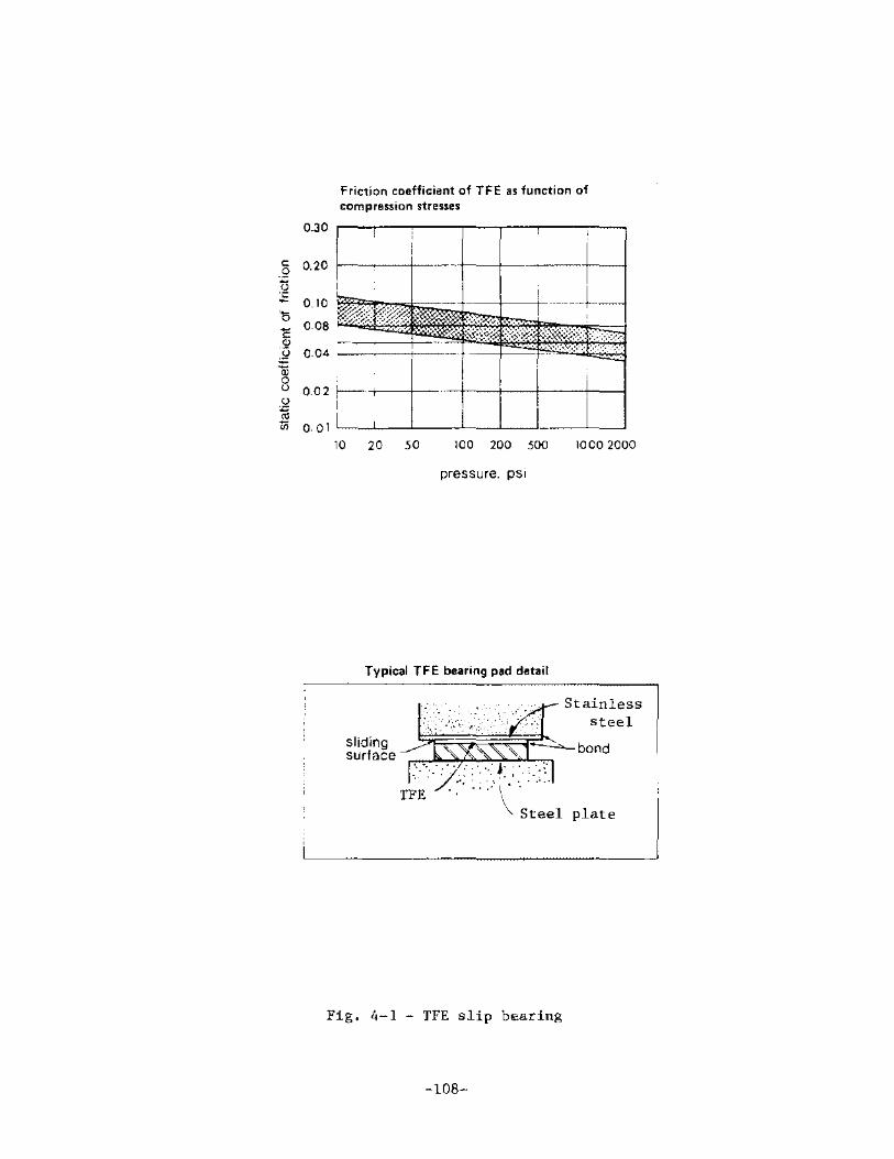
0.30
Friction coefficient of TFE as function of compression stresses
_§ 0.20
~ 0_10 '0 __ 0_08
~ 0_04 ===::j==r--r-~ § g 0.02 f--~-+- -+-+-+--+---1 • "1ii 0.01 L_L_--'-__ --'-_-'_-li ___ -"_---'
10 20 50 100 200 500 1000 2000
pressure. pSI
Typical TFE bearing pad detail
sliding surface
Stainless steel
~~~~-~·'-~~~~E~~ bond
T;~/,r ... \ \,. Steel plate
Fig. 4-1 - TFE slip bearing
-108-

The following arc simple, design criteria for oonre-strained
elastomcric bearing pads. These criteria recognize the presence
of slippage in pad shear movements and are stated in terms of
maxiIllJrn allowable one",""",ay horizontal movement expressed in terms
of pad thickness.
Design Recommendations
1. Use unfactored service loads for design.
2. At the suggested maximum uniform compressive stresses, in
stantaneous vertical strains of 10 to 20 percent in the pad
will generally result. The instantaneous compressive
strains may double when nonparallel bearing surfaces are
present. In addition, these uniform and nonuniform instan-
taneous strains may increase approximately 25 to 100 percent
from long-term creep effects. The higher creep values are
associated with high sustained design load stresses on the
pads. These instantaneous and creep movements should be ac
counted for in design and detailing.
3. Length of unreinforced pad > 5 x thickness for stability.
Width of pad ~5 x thickness for stability.
4. t 2- 1/4 in. for stemmed members and 3/8 in. for beams.
5. Shear force has been shown to be a function of slip in the
chloroprene or random oriented fiber pad and Fig. 4-2 should
be used to estimate these forces.
6. The portion of a pad outside of the covering bearing surface
is not considered in these recommendations. If addit ional
pad area is provided for case in placement, it should be ig
nored in calculating pad stresses, stability and movements.
7. Unreinforced pads with shape factor (S) less than 2 should
be avoided under tees and pads with shape factor less than 3
should be avoided under beams.
8. The sustained dead load compressive stress on an unrein
forced chloroprene bearing pad should be limited to 500 psi.
9. In checking long-term slowly applied pad shear deformation
due to creep and shrinkage of concrete members, the long
term concrete movement may be reduced by one-half because of
compensating creep and slip in the bearing pad.
-109-

p
Type of Pad Material
Unreinforced Chloroprene or Rubber
(AASHTO Sec. 25)
Random fiber Reinforced Elastomeric
Duck Layer Reinforced Elastorneric (AASHTO 2. 10. 3 (L ) &
MIL-{O-882 )
(1) See 7 and 8.
SINGLE LAYER BEARING PADS FREE TO SLIP
Allowable compressive
stress (ps i)
= 4DS (l )
< 800 -
1000 + laOS < 1500 -
< 2000 -
D = Durometer (Shore A Hardness)
S = Shape Factor '"
Loaded area
L x W
2 (L-tW)t
Area free to bulge
t == pad thickness (in.)
l::. "" Design Horizontal Movement at End of ~lember in one direction (in. )
Hardness ~1inil1Um pad >taxi Trum Range thickness allowable
(D ) for horizontal rotation movement of (in critical
" direction) (in. )
50 through 1.41'1 (3 ) 0.3t(2)
70 L or W
80+10 1. 46 (3) 0.3t(2) - L or W
Data 90+10 not 0.3t(2) - available L or W
I 1
(2) The maxiwm rotation angle in either the L or W direction should be compared with the appropriate limit.
(3) If the pad is sheared in two directions, the maximum of the two horizontal movements should be used. The values in the table are based on Sliding criteria. If sliding is not critical or testing indicates more advantageous conditions, thinner pads may be used.
-110-

210
'0' ON {;ONCRETE
IBO
I- ~
<I "-. 150 • 0'" <10 0..1'-
IL Z ° 120 ° Z (/)<1
ON STEEL (/)Il: '0' WI-Il:<n I- 90 (/) W
ON CONCRETE
~ Il: CHLOROPftENE <I 0..
ONSTEE W -' :r: <n 60 <n
0 Z
Note: <I Suitable safety factors Il: 30 should be applied <I depending on uses W :r: <n
a 0 400 BOO 1200 1600 2000
COMPRESSIVE STRESS ON PAD, ere, psi
Fig. 4-2 - Design chart for estimating shear stress or force on member ends (for small pads)
-111-

Prestressed Concrete Institute 201 North Wells Street Chicago. Illinois 60606 Telephone 312/346-4071 TR-4-85