Bearing capacity of concrete hinges subjected to eccentric ...

ORIGINAL ARTICLE
Creep and cracking of concrete hinges: insight from centricand eccentric compression experiments
Thomas Schlappal . Michael Schweigler . Susanne Gmainer . Martin Peyerl .
Bernhard Pichler
Received: 9 March 2017 / Accepted: 4 November 2017 / Published online: 22 November 2017
� The Author(s) 2017. This article is an open access publication
Abstract Existing design guidelines for concrete
hinges consider bending-induced tensile cracking, but
the structural behavior is oversimplified to be time-
independent. This is the motivation to study creep and
bending-induced tensile cracking of initially mono-
lithic concrete hinges systematically. Material tests on
plain concrete specimens and structural tests on
marginally reinforced concrete hinges are performed.
The experiments characterize material and structural
creep under centric compression as well as bending-
induced tensile cracking and the interaction between
creep and cracking of concrete hinges. As for the latter
two aims, three nominally identical concrete hinges
are subjected to short-term and to longer-term eccen-
tric compression tests. Obtained material and struc-
tural creep functions referring to centric compression
are found to be very similar. The structural creep
activity under eccentric compression is significantly
larger because of the interaction between creep and
cracking, i.e. bending-induced cracks progressively
open and propagate under sustained eccentric loading.
As for concrete hinges in frame-like integral bridge
construction, it is concluded (i) that realistic simula-
tion of variable loads requires consideration of the
here-studied time-dependent behavior and (ii) that
permanent compressive normal forces shall be limited
by 45% of the ultimate load carrying capacity, in order
to avoid damage of concrete hinges under sustained
loading.
Keywords Integral bridge construction �Mechanized tunneling � Segmented tunnel lining �Tensile cracking of concrete � Digital image
correlation
1 Introduction
Concrete hinges were invented by Freyssinet [1, 2].
They are unreinforced or marginally reinforced necks
in reinforced concrete structures, such as, e.g. supports
in integral bridge construction [3–10] and segment-to-
segment interfaces of segmented linings used in
mechanized tunneling [11–28]. Eventually a few pairs
of crossed steel rebars (or bolts) run across a concrete
hinge. Their cross-over point is typically at the center
of the neck. Therefore, the bending stiffness of the
neck is significantly smaller than the ones of the two
connected reinforced concrete parts. The correspond-
ing concentration of bending deformation at the
concrete hinge results, already under regular service
loads, either in tension-induced cracking of initially
T. Schlappal � M. Schweigler � B. Pichler (&)
Institute for Mechanics of Materials and Structures, TU
Wien – Vienna University of Technology, Karlsplatz
13/202, 1040 Vienna, Austria
e-mail: [email protected]
S. Gmainer � M. Peyerl
Smart Minerals GmbH, Reisnerstraße 53, 1030 Vienna,
Austria
Materials and Structures (2017) 50:244
https://doi.org/10.1617/s11527-017-1112-9

monolithic necks, or in partial separation of segment-
to-segment interfaces. Both effects further reduce the
effective bending stiffness of the neck. This further
promotes the ability of concrete hinges to develop
relative rotation angles.
Current design guidelines for concrete hinges are
based on pioneering developments of Leonhardt and
Reimann [5]. In the field of integral bridge construc-
tion, these guidelines were further developed by
Monnig and Netzel [29], Marx and Schacht [6], as
well as by Morgenthal and Olney [7]. As for mech-
anized tunneling, Gladwell [30] developed a moment-
rotation relation for concrete hinges representing
longitudinal joints. A few years later, Janßen [17]
adapted the formulas of Leonhardt and Reimann to
interfaces between reinforced concrete segments.
These formulas are up to date the golden standard
[13, 27, 28, 31, 32]. All described guidelines and
recommendations provide unique relationships
between bending moment and rotation angle, see their
comparison with available experimental data in Fig. 1.
Concrete hinges are nowadays experiencing a
renaissance in integral bridge construction. Examples
are (i) the viaduct ‘‘Weißenbrunn am Forst’’, Ger-
many, which was constructed in 2011, see [36], and
(ii) the Huyck-bridge, Austria, which was finished in
2014, see [37].
Since the 1960s, many concrete hinges were
investigated experimentally, e.g., by Tourasse [34],
Base [33], Dix [38], Leonhardt and Reimann [5],
Fessler [35], Franz and Fein [39], as well as Hordijk
and Gijsbers [40]. The underlying test protocols are
typically structured in two phases. At first, a com-
pressive axial force was applied and kept constant
thereafter. This was followed by imposing a rotation
angle and keeping it constant thereafter. The first type
of loading resulted in creep of concrete, and the
second type in stress relaxation. This mixed vis-
coelastic behavior of concrete was one motivation for
the current contribution, where we focus on creep of
concrete and of concrete hinges subjected to com-
pression and bending. The second motivation is that
the interaction between bending-induced tensile
cracking and creep of initially monolithic concrete
hinges is an open research question.
We report on experiments both on the material level
of plain concrete and on the structural scale of initially
monolithic concrete hinges. As for material testing,
concrete prisms are subjected to centric compression,
in order to quantify material creep functions at load
levels being equal to virtually 20% of the short-term
uniaxial compressive strength. As for structural test-
ing, initially monolithic concrete hinges are subjected
to centric and eccentric compression. The underlying
aim is to study (i) structural creep under centric
loading, (ii) tensile cracking under short-term eccen-
tric loading, (iii) structural creep under eccentric
compression at virtually 25% of the ultimate load
carrying capacity, and (iv) the interaction between
bending-induced tensile cracking and creep. Rotations
of the concrete hinges are quantified by means of
Inductive Displacement Transducers (LVDTs). Crack
propagation is observed with a non-contact displace-
ment measurement system, based on Digital Image
Correlation (DIC).
The present contribution is structured as follows.
Materials and test specimens are discussed in Sect. 2.
Characterization of linear creep of plain concrete
under uniaxial compression is the topic of Sect. 3.
Structural testing of concrete hinges up to service
loads as well as up to their load carrying capacity are
described in Sects. 4 and 5, respectively. Experimen-
tal results are analyzed in Sect. 6 and discussed in
Sect. 7, including implications for design guidelines
and for the necessary consideration of time-dependent
behavior of concrete hinges in integral bridge con-
struction. Conclusions are drawn in Sect. 8. Through-
out this work, compression is considered by a positive
sign.
Fig. 1 Dimensionless relation between bending momentM and
relative rotation angle Du (‘‘Leonhardt and Reimann’’-dia-
gram): modeled relationships by Gladwell [30], Leonhardt and
Reimann [5], and Janßen [17], as well as experimental data from
Base [33], Tourasse [34], and EMPA [35]; N ¼ normal force,
e ¼ eccentricity, a ¼ width of neck, b ¼ depth of neck, E ¼Young’s modulus of concrete
244 Page 2 of 16 Materials and Structures (2017) 50:244

2 Materials and test specimens
2.1 Concrete and steel
Concrete C 35/45 F45 GK16 B5 [41] is produced with
a commercial CEM II/A-L 42.5 N cement [41], Vien-
nese tap water, and calcite aggregates with a maxi-
mum size of aagg ¼ 16 mm. The initial water-to-
cement mass ratio amounts to w=c ¼ 0:48, the initial
aggregate-to-cement mass ratio to a=c ¼ 3:97, and the
initial mass density to q ¼ 2318 kg/m3. The cube
compressive strength fc;cube and Young’s modulus E
are determined 28 days after production, following the
Austrian standards for testing of concrete [42], as
fc;cube ¼ 56:25MPa; E ¼ 34:75GPa: ð1Þ
The cube compressive strength allows for estimating
the uniaxial compressive strength fc as [43]
fc ¼fc;cube
1:2¼ 46:88MPa: ð2Þ
The produced concrete is well suited for bridge
applications. In order to provide adequate frost-thaw
resistance within exposure class XF3, it contains
2.5–5.0 volume percent entrained air.
As for the rebars, steel quality B550 A was chosen.
The von Mises yield stress fy and Young’s modulus Es
of this material amount to
fy ¼ 550MPa; Es ¼ 200GPa: ð3Þ
2.2 Plain concrete prisms and reinforced concrete
hinges
As for material testing of plain concrete, 10 prisms are
produced. They exhibit nominal dimensions of 75 mm
� 75 mm � 250 mm, see Fig. 2.
As for structural testing, three marginally rein-
forced concrete hinges are produced. Their geometric
shape (i) is inspired by the concrete hinges of Huyck-
bridge [37], and (ii) complies with the design guide-
lines of Leonhardt and Reimann [5]. In more detail, the
concrete hinges exhibit width, height, and depth
amounting to 25, 35, and 40 cm, respectively, see
Fig. 3. Lateral notches are 8.75 cm deep and front
notches 5 cm, such that the cross-sectional area of the
neck, Ac, amounts to
Ac ¼ 7:5� 30 ¼ 225:00 cm2: ð4Þ
Both at the top and at the bottom of the concrete
hinges, a steel plate of 2 cm thickness is welded (well
before casting of fresh concrete) to the neighboring
reinforcement cage (Fig. 3). These plates ensure an
effective distribution of concentrated external line
loads. The top and bottom reinforcement cages are
connected by three pairs of crossed steel rebars, with
cross-over points right at the center of the neck, see
Fig. 3. They exhibit a diameter of 0.8 cm, such that the
total cross-sectional area of reinforcements running
across the neck, As, amounts to
As ¼ 6� 0:82p=4 ¼ 3:02 cm2: ð5Þ
The reinforcement ratio . follows as
Fig. 2 Plain concrete prisms used for material testing: test
specimens consist of two prisms in serial arrangement
8.75 7.50 8.75
142
214
335
front view
25
concrete
reinforcementsteel plates
4030 55
side view
[cm]
Fig. 3 Geometric dimensions and rebar positions of the tested
reinforced concrete hinges
Materials and Structures (2017) 50:244 Page 3 of 16 244

. ¼ As=Ac ¼ 1:3%: ð6Þ
Three batches of fresh concrete are mixed in a
laboratory mixer. From each batch, two to four plain
concrete prisms and one reinforced concrete hinge are
produced at the same time. Formworks are stripped
24 h after production. After that, all specimens are air
cured in order to simulate a practical real-life appli-
cation. In other words, the specimens were allowed to
dry in an environment with temperature und relative
humidity ranging in estimated intervals from 24 to
29 �C and from 50 to 70 %, respectively.
3 Material testing: creep characterization of plain
concrete
Plain concrete exhibits linear creep as long as the
stress level r is small compared to the uniaxial
compressive strength fc, and nonlinear creep for larger
stress levels. The transition from linear to nonlinear
creep is still not fully understood. Eurocode 2—
regulating the design of concrete bridges, see [44]—
suggests that the transition threshold amounts to
r=fc ¼ 0:45 while Mazzotti and Savoia [45] recom-
mend a more conservative value amounting to
r=fc ¼ 0:20.
This is the motivation to perform five linear creep
tests with compressive stress level r � 0:2 fc, on an
electromechanical testing machine of type Zwick/
Roell Z050. Loading is applied via two metal prisms
with a cross-section of 75 � 75 mm2, and a height of
20 mm, see Fig. 2.
Compression-induced shortening of the specimens
is measured directly at the surface of the specimens. In
order to increase the measurement length, two con-
crete prisms are put into a serial arrangement, see
Fig. 2 and Table 1. To this end, the two prisms are
pushed together by hand and the prism-to-prism
interface is connected laterally using an adhesive tape
(Fig. 2). The shortening of the specimens is measured
by four Inductive Displacement Transducers (LVDTs)
of type HBM W1/2mm-T. They are mounted to the
specimen by means of LVDT holders which are
attached to the specimen by means of screws. The
LVDT holders are located at a distance of 75 mm to
the top and bottom load platens (Fig. 2), i.e. they
measure the shortening of the specimen in the central
region which is free of friction-induced, unavoidable,
and self-equilibrated shear stresses activated in the
interfaces between specimen and load platens, see [46]
for more details. Firm contact in the prism-to-prism
interface avoided possible sliding or rotation/bending
of the prisms. This is underlined by the four individual
LVDT measurements which show no indication of a
significant eccentricity of loading.
In order to avoid temperature-induced deformation
of the specimens during creep testing, the experiments
are carried out in an insulated test chamber condi-
tioned to 20 �C with a temperature control unit Lauda
RK8 KP. In addition, after closing the test chamber
and before starting the creep tests, specimens are
allowed to achieve isothermal conditions during a
waiting period amounting to more than 24 h.
The creep tests are carried out as follows. All of the
five specimens are involved in a linear creep test.
During the described waiting period before actual
loading, the specimens are subjected to a compressive
force of 2 kN, in order to establish good contact along
the interfaces between load platens and specimen as
well as the prism-to-prism interface in the middle of
the specimen. Compressive loading is increased with a
force rate amounting to 1 kN/s up to 49 kN, and the
load level r � 0:2 fc is kept constant for 20 h (spec-
imens 1, 2, and 3) and for 12 h (specimens 4 and 5),
respectively.
Table 1 Properties of plain
concrete specimens used for
characterization of linear
creep behavior
No. Height h (mm) Cross-section a1 � a2 (mm2) Mass m (kg) Mass density q (kg/m3)
1 501.10 75.48 9 76.83 6.794 2338.27
2 500.90 75.55 9 75.48 6.706 2347.87
3 501.50 75.60 9 76.05 6.752 2341.75
4 501.50 75.43 9 76.33 6.764 2342.88
5 500.65 74.98 9 75.40 6.672 2357.40
244 Page 4 of 16 Materials and Structures (2017) 50:244

4 Structural testing of concrete hinges
up to service loads
A first set of structural tests deals with creep and
tensile cracking of concrete hinges subjected to centric
and eccentric service loads. The test setup is described
in Sect. 4.1. The extensional stiffness of undamaged
concrete hinges and their structural creep behavior
under centric compression is the topic of Sect. 4.2.
The bending stiffness of undamaged concrete hinges
and the development of tensile cracking as a function
of eccentric loading is studied in Sect. 4.3. Finally, the
coupling between creep and tensile cracking of
concrete hinges is analyzed in eccentric creep tests,
see Sect. 4.4.
4.1 Test setup and measurement equipment
Concrete hinges are subjected, 26 days after produc-
tion, to compressive line loads using a servo-hydraulic
testing machine of the type Walter and Bai DLFV-
250DZ-10-D. The loadmeasurement cell of the testing
machine is used to carry out force-controlled tests,
where compressive normal forces N are imposed on
the concrete hinges. Tests are carried out with and
without eccentricity of the normal force. In case of
load eccentricity e, concrete hinges are subjected to
coupled compression and bending, whereby the
bending moment M is proportional to the normal
force:
M ¼ N � e: ð7Þ
Ten LVDTs of type HBMW1/2mm-T are mounted to
the lateral surfaces of the concrete hinges, in order to
measure changes of the notch mouth opening dis-
placements of the lateral notches, see Fig. 4. The
measurement length of the displacement sensors,
measured in loading direction, amounts to
‘e ¼ 65mm. The LVDTs are arranged symmetrically
in thickness direction with a sensor-to-sensor distance
amounting to 80 mm. The measurement axis of each
LVDT exhibits a normal distance of 22 mm to the
lateral surface of the concrete hinge, i.e. opposite
LVDTs exhibit a mutual distance which amounts to
‘u ¼ 250mmþ 2 � 22mm ¼ 294mm.
A Digital Image Correlation (DIC) system of type
Dantec Dynamics Q 400, is used to observe tensile
crack propagation along the notch roots of the front
side and the back side notches. To this end, both
notches are monitored with a pair of 5 megapixel
cameras each. Application of two cameras per notch
allows for recording three-dimensional displacement
fields, whereby the in-plane displacements are of
special interest. The observed field of view is approx-
imately equal to 12 cm� 10 cm. Fine speckle patterns
are sprayed to the notch roots prior to testing, with a
desired point size amounting to 2 to 3 pixels. A facet
size of 21 pixel and grid spacing of 17 pixel are
chosen, for further specifications of the DIC see
Table 2.
4.2 Creep under centric compression (200 kN)
Centric compression tests up to 200 kN are used to
characterize the extensional stiffness of undamaged
concrete hinges and their structural creep behavior
under pure normal force (no bending). To this end,
each of the three concrete hinges is installed into the
testing machine, resting on temporary supports. After
fine tuning the position and installing the deformation
measurement equipment, loading is increased up to
4 kN. This allows for removing the temporary
supports, because 4 kN loading is sufficient to keep
the concrete hinge in the desired position (no tipping
over). Reference readings of the deformation mea-
surement system are taken. Finally, the loading is
increased with a force rate amounting to 5 kN/s up to
Fig. 4 Structural testing of concrete hinges up to service loads:
Five Inductive Displacement Transducers are mounted on each
lateral surface of the concrete hinges; two pairs of cameras of a
Digital Image Correlation system are used to monitor tensile
cracking at the notch roots of the front side and the back side
notches (not shown); normal forces N are imposed in form of
line loads, acting with eccentricity e, resulting in combined
compression and bending, see also Eq. (7); temporary supports
are removed during testing
Materials and Structures (2017) 50:244 Page 5 of 16 244
200 kN. This loading is kept constant for 4 h, followed
by complete unloading, using again the force rate of
5 kN/s.
4.3 Bending and tensile cracking under short-term
eccentric compression up to 200 kN
Minutes-long eccentric compression tests are used to
characterize (i) the bending stiffness of undamaged
concrete hinges and (ii) the development of tensile
cracking as a function of the eccentricity e and of the
compressive normal force N. This requires a careful
development of the test design described next.
As for characterization of the undamaged bending
stiffness of the investigated concrete hinges, a trade
off must be found between (i) a large eccentricity,
resulting in relatively large bending, see Eq. (7) and,
hence, in relatively large rotation angles, as well as (ii)
a small eccentricity, ensuring that bending-induced
tensile stresses in the neck region remain smaller than
the tensile strength of concrete. The latter cannot be
directly measured in the present case, because the test
design must be finished well before the specimens
reach the testing age. Therefore, the tensile strength is
estimated, based on the known compressive strength fcaccording to Eq. (2), using the following standard
relation [43]
ft ¼ �0:3MPa � fc
1MPa
� �2=3
¼ �3:9MPa: ð8Þ
Two-dimensional plane strain Finite Element analyses
of the investigated concrete hinges provide quantita-
tive insight into the stress concentrations resulting
from loading by a normal force N and by a bending
momentM, respectively. Denoting the cross-sectional
area of the neck as a b and its beam theory-related
elastic section modulus as a2 b=6, the largest tensile
stress in the neck region follows as
max rt ¼ 2:77N
a b� 2:00
6M
a2 b; ð9Þ
where 2.77 and 2.00 are numerically determined stress
increase factors relative to the stress levels foreseen by
beam theory. Specializing Eq. (9) for M according to
Eq. (7), and the resulting expression for a ¼ 75mm,
for b ¼ 300mm, for the targeted maximum loading
N ¼ 200 kN, and for an eccentricity e ¼ 20mm,
delivers a maximum tensile stress which is only
slightly smaller than the tensile strength:
max rt ¼ �3:8 _2MPa: ð10Þ
In other words, Finite Element analyses suggest that a
normal force N ¼ 200 kN, acting with an eccentricity
of e ¼ 20mm on the herein investigate concrete
hinges, can be expected to result in large tensile
stresses, but small enough to keep the concrete hinges
intact (no tensile cracking).
As for studying the development of tensile cracking
as a function of the eccentricity e and of the
compressive normal force N, a maximum reasonable
eccentricity needs to be defined. In this context, we
consider the design guidelines of Leonhardt and
Reimann [5], which exhibit a limit of application
reading as
max e ¼ a=3; ð11Þ
because the guidelines envision (i) that for e ¼ a=3
tensile cracking will extend across half of the neck
width, i.e. right to the center of the concrete hinge, and
(ii) that an even larger extension of tensile cracking
Table 2 Specifications and settings used for the DIC mea-
surements and evaluation, respectively
Dantec Dynamics Q-400 ISTRA 4.4.2
Specifiations
Number of 5 megapixel cameras used 2� 2
Names of front side cameras Cam1/2
Names of back side cameras Cam3/4
Cam1-to-Cam2 distance 60 cm
Cam3-to-Cam4 distance 60 cm
Camera-to-specimen distance 82 cm
Exposure Cam1/2 Red light
Exposure Cam3/4 Diffuse light
Facet size 21 pixel
Grid spacing 17 pixel
Object lens 2.8/50
F-number 5.6–11
Shutter speed 80 ms
Settings for evaluation
Crack identification: upper threshold 0.006 [–]
Crack identification: lower threshold 0.002 [–]
Contour smoothing: Disabled
Displacement smoothing: Spline
Grid reduction factor 1
Smoothness factor -0.5
244 Page 6 of 16 Materials and Structures (2017) 50:244

shall be avoided. Specializing Eq. (11) for the neck
width a ¼ 75mm of the investigated concrete hinges
delivers the maximum eccentricity to amount to
e ¼ 25mm. This eccentricity is chosen for the load
carrying capacity tests described in Sect. 5.
As for the tests with service loadsN� 200 kN, three
different eccentricities are chosen:
e 2�20mm ; 22mm ; 24mm
�: ð12Þ
Testing is started with the smallest eccentricity
e ¼ 20mm. One after the other, the concrete hinges
are installed into the testing machine, resting on
temporary supports. After fine tuning the position and
installing the deformation measurement equipment,
loading is increased up to 0.2 kN. This allows for
removing the temporary supports, because 0.2 kN
loading is sufficient to keep the concrete hinge in the
desired position (no tipping over). Reference readings
of the deformation measurement system are taken.
Right before starting the test, the DIC system is
activated to take pictures with a frequency amounting
to 2 Hz. Loading is increased with a force rate
amounting to 5 kN/s. Once 25 kN are reached, the
loading process is stopped for a waiting period of 5 s,
such that the DIC system takes 10 pictures at that load
level. After that, loading is increased by another
25 kN, followed by the next waiting period. Step-by-
step loading is increased up to a maximum load of
200 kN. After another waiting period of 5 s, the
concrete hinge is completely unloaded with a force
rate of 5 kN/s. After that, the eccentricity of the
concrete hinge is increased to 22mmwith the help of a
special threaded bolt assembly, where turning of
screws results in a controlled lateral displacement of
the concrete hinge. The test protocol described above
is repeated, followed by another increase of the
eccentricity to 24mm and another repetition of
stepwise loading up to 200 kN and unloading. There-
after, testing is continued with hours-long creep
experiments, as described next.
4.4 Creep under longer-term eccentric
compression (175 kN)
Hours-long eccentric compression tests are used to
characterize (i) the structural creep behavior under
combined compression and bending as well as (ii) the
interaction between creep and bending-induced tensile
crack propagation. With these two aims in mind,
continued testing of concrete hinges was organized as
follows.
A 16 h-long creep test is carried out with eccen-
tricity e ¼ 24mm and a normal force N ¼ 175 kN.
After installing the respective concrete hinge into the
testing machine, fine tuning the position, installing the
deformation measurement equipment, preliminary
loading up to 0.2 kN, removal of the temporary
supports, and taking reference readings of the defor-
mation measurement system, loading is increased with
a force rate amounting to 5 kN/s up to 175 kN, and this
load level is kept constant for 16 h. During this creep
test, the DIC system takes 1 picture every 15 min.
5 Structural testing of concrete hinges up to their
load carrying capacity
A second set of structural tests deals with the load
carrying capacity of concrete hinges subjected to
eccentric loads. These tests are carried out in order to
characterize the relation between eccentric loading
and rotation angle, up to structural failure.
5.1 Test setup and measurement equipment
Concrete hinges are subjected, 40 days after produc-
tion, to compressive line loads using a servo-hydraulic
testing machine of type Schenk POZ 0367. The load
carrying capacity tests are carried out with an eccen-
tricity of e ¼ a=3 ¼ 25mm, which refers to the limit
of application of the design guidelines of Leonhardt
and Reimann [5].
Eight LVDTs of type HBM WI 10 are mounted to
the lateral surfaces of the concrete hinges, in order to
measure changes of the notch mouth opening dis-
placements of the lateral notches. The measurement
length in loading direction amounts to ‘LCCe ¼ 50mm.
The LVDTs are arranged symmetrically in thickness
direction with a sensor-to-sensor distance amounting
to 100 mm. The measurement axis of each LVDT
exhibits a normal distance of 35 mm to the lateral
surface of the concrete hinge, i.e. opposite LVDTs
exhibit a mutual distance which amounts to
‘LCCu ¼ 250mmþ 2 � 35mm ¼ 320mm.
Materials and Structures (2017) 50:244 Page 7 of 16 244

5.2 Load carrying capacity tests
In eccentric compression tests (e ¼ 25mm) the com-
pressive normal force N is increased up to the load
carrying capacity. After installing the respective
concrete hinge into the testing machine, fine tuning
the position, installing the deformation measurement
equipment, preliminary loading up to 1 kN, removal
of the temporary supports, and taking reference
readings of the deformation measurement system,
the line-load is increased. This is carried out by
manually increasing the displacement of the load
application system, with a target rate amounting to
0.2 mm/min. Once 100 kN is reached, the loading
process is stopped for 1 min, in order to quantify the
time-dependent structural response at that load level.
After that, loading is increased by another 100 kN,
followed by the next waiting period. Step by step
loading is increased up to the load carrying capacity.
The latter is assumed to be reached once the rotation
angle increases significantly while no significant
increase of the normal force is observed. Unloading
is performed by using again the rate of 0.2 mm/min.
The duration of one test is approximately 30 min.
6 Test evaluation and results
6.1 Postprocessing of LVDT measurements
Individual LVDT readings are used to quantify the
shortening and the rotation angle of the neck region.
To this end, readings on both sides (left and right) are
averaged
Dlleft ¼1
ns
Xnsi¼1
Dlleft;iðtÞ ð13Þ
Dlright ¼1
ns
Xnsi¼1
Dlright;iðtÞ ð14Þ
where ns denotes the number of sensors mounted on
each side of the concrete hinges.1 The shortening of
the neck region, Dl, is quantified as
Dl ¼ Dlleft þ Dlright2
ð15Þ
and the rotation angle as
Du ¼ Dlleft � Dlright‘u
�������� ð16Þ
where ‘u denotes the distance of opposite LVDTs, see
Sects. 4.1 and 5.1.
6.2 Material creep tests
The five creep tests performed under � 20 % of the
compressive strength yield creep strain evolutions
reminiscent of a power-law, see Fig. 5. Three out of
five tests delivered virtually the same creep response,
framed by the results of the other two tests. This
indicates a satisfactory reproducibility of the
experiments.
6.3 Centric compression of concrete hinges
(200 kN)
All three concrete hinges showed virtually the same
behavior during the creep tests. The force-shortening
relationships during 40 s-long loading are practically
linear. The shortening of the neck, just after arriving at
200 kN, amounts to� 35 lm, see the circles in Fig. 6.
During the subsequent 4 h-long creep period, the
shortening increases nonlinearly by some 20 %, again
reminiscent of a power-law creep evolution, see
Fig. 6.1 One of the outermost LVDTs failed during one test with
N � 200 kN. In the interest of comparability of different tests, nsis set equal to 3 referring to the three central LVDTs of each
side.
Fig. 5 Evolution of creep strains of concrete under constant
load (0:2 � fc): results from testing of five plain concrete
specimens
244 Page 8 of 16 Materials and Structures (2017) 50:244

6.4 Bending stiffness of concrete hinges and crack
propagation during short-term eccentric
compression tests up to 200 kN
Increasing eccentric loading in steps of 25 kN and
interrupting the loading process for 5 s at each
completed loading step, demonstrates that concrete
hinges are very creep active even under small degrees
of utilization (relative to the load carrying capacity),
see the visible load plateaus highlighted in red color in
Fig. 7. Subtracting rotation angles developing during
the 5 s waiting periods from the total measurements,
would result in rotation angles that increase virtually
linearly with increasing loading, with a slope that
decreases with increasing eccentricity.
When it comes to identification of crack length at
the different load plateaus, we consider a region to be
cracked, if the maximum strain in loading direction is
larger than a threshold. Definition of the latter is a
challenging task given the small strain amplitudes
before tensile cracking. We here defined an upper and
a lower threshold which are expected to be bounds
containing the real crack initiation strain, see Table 2.
Already with the first eccentricity, nominally amount-
ing to 20 mm, first cracks developed at load levels
amounting to 175 and 200 kN, see the triangles in
Fig. 8.2 After unloading, the eccentricity was
increased by nominally 2 mm. Since DIC allows for
quantifying rigid body motions, the actual lateral
movement could be shown to be slightly larger, i.e.
2.13 mm for concrete hinge 1. When reloading with
the increased eccentricity to the first intermediate load
level of 25 kN, the already existing crack opened
visibly. Crack propagation was observed for loading
beyond 100 kN, see the circles in Fig. 8. Similar
observations were made also with the third eccentric-
ity and the final crack length amounted to some 20% of
the neck width, see the squares in Fig. 8.
Fig. 6 Measured shortenings of the neck regions of three
concrete hinges as a function of time; loading is increased with a
force rate of 5 kN/s up to 200 kN and kept constant thereafter,
demonstrating structural creep under centric compression
Fig. 7 Measured rotation angles of three concrete hinges as a
function of eccentricity and loading; loading is increased with a
force rate of 5 kN/s and held constant every 25 kN for 10 s;
creep deformation developing during these intermediate load
plateaus are highlighted in red color. (Color figure online)
Fig. 8 Measured average crack length (=mean of front-side and
back-side crack length) of the concrete hinge 1 determined from
DIC with settings according to Table 2, with nominal eccen-
tricities of 20, 22, and 24 mm, as well as loading up to 200 kN
2 DIC images of concrete hinge 2 could not be evaluated due to
insufficient contrast. Results regarding concrete hinge 3 are
similar to the ones of concrete hinge 1, but they cannot be shown
due to the limited number of allowed figures.
Materials and Structures (2017) 50:244 Page 9 of 16 244
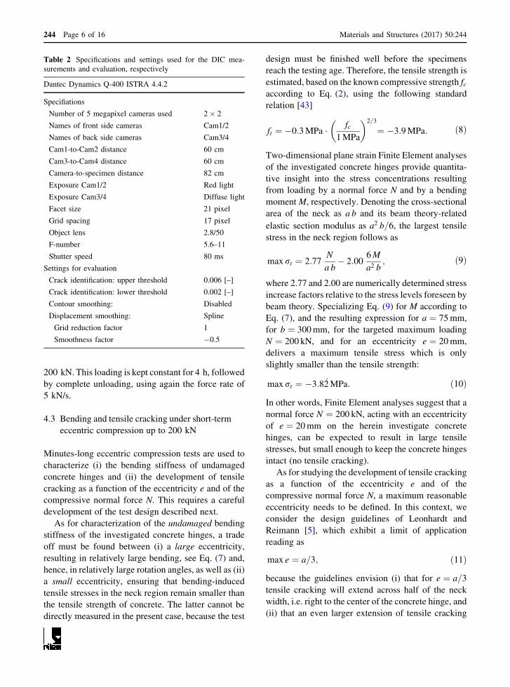
6.5 Creep and tensile cracking of concrete hinges
during longer-term eccentric compression
(175 kN)
All three concrete hinges showed virtually the same
behavior during the eccentric creep tests. The rela-
tionships between the eccentric force and the rotation
angle are practically linear during the loading period
amounting to 35 s. The rotation angle of the neck, just
after arriving at 175 kN, amounts to � 0:9 mrad, see
the circles in Fig. 9. During the subsequent 16 h-long
sustained eccentric loading, the rotation angle
increases nonlinearly by around 50%, again reminis-
cent of a power-law creep evolution, see Fig. 9.
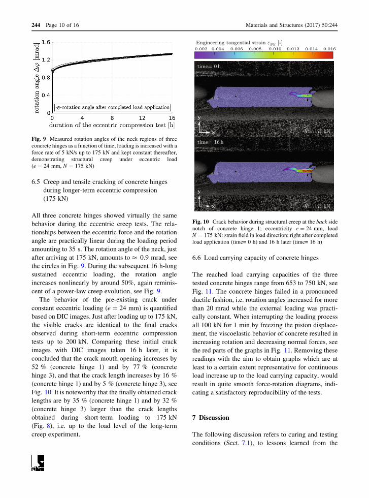
The behavior of the pre-existing crack under
constant eccentric loading (e ¼ 24 mm) is quantified
based on DIC images. Just after loading up to 175 kN,
the visible cracks are identical to the final cracks
observed during short-term eccentric compression
tests up to 200 kN. Comparing these initial crack
images with DIC images taken 16 h later, it is
concluded that the crack mouth opening increases by
52 % (concrete hinge 1) and by 77 % (concrete
hinge 3), and that the crack length increases by 16 %
(concrete hinge 1) and by 5 % (concrete hinge 3), see
Fig. 10. It is noteworthy that the finally obtained crack
lengths are by 35 % (concrete hinge 1) and by 32 %
(concrete hinge 3) larger than the crack lengths
obtained during short-term loading to 175 kN
(Fig. 8), i.e. up to the load level of the long-term
creep experiment.
6.6 Load carrying capacity of concrete hinges
The reached load carrying capacities of the three
tested concrete hinges range from 653 to 750 kN, see
Fig. 11. The concrete hinges failed in a pronounced
ductile fashion, i.e. rotation angles increased for more
than 20 mrad while the external loading was practi-
cally constant. When interrupting the loading process
all 100 kN for 1 min by freezing the piston displace-
ment, the viscoelastic behavior of concrete resulted in
increasing rotation and decreasing normal forces, see
the red parts of the graphs in Fig. 11. Removing these
readings with the aim to obtain graphs which are at
least to a certain extent representative for continuous
load increase up to the load carrying capacity, would
result in quite smooth force-rotation diagrams, indi-
cating a satisfactory reproducibility of the tests.
7 Discussion
The following discussion refers to curing and testing
conditions (Sect. 7.1), to lessons learned from the
Fig. 9 Measured rotation angles of the neck regions of three
concrete hinges as a function of time; loading is increased with a
force rate of 5 kN/s up to 175 kN and kept constant thereafter,
demonstrating structural creep under eccentric load
(e ¼ 24 mm, N ¼ 175 kN)
Engineering tangential strain εyy [-]0.002 0.016
y
x
y
x
N= 175 kN
time= 16 h
N= 175 kN
0.006 0.010 0.012 0.0140.004 0.008
time= 0h
Fig. 10 Crack behavior during structural creep at the back side
notch of concrete hinge 1; eccentricity e ¼ 24 mm, load
N ¼ 175 kN: strain field in load direction; right after completed
load application (time= 0 h) and 16 h later (time= 16 h)
244 Page 10 of 16 Materials and Structures (2017) 50:244

numerical re-analysis of the bearing capacity tests
(Sect. 7.2), to the interaction between creep and
bending-induced tensile cracking of initially mono-
lithic concrete hinges (Sect. 7.3), to implications
concerning design guidelines (Sect. 7.4), and to the
time-dependent behavior of concrete hinges in integral
bridge construction (Sect. 7.5).
7.1 Curing and test conditions
In order to simulate a practical real-life application, all
tested specimens were air-cured after formwork
removal. Drying resulted in moisture gradients and
potentially even in a premature stopping of the
hydration process in close-to-surface subvolumes of
the specimens. In addition, drying shrinkage strains
and autogeneous shrinkage strains of the concrete
hinges were restrained by the rebars and the steel
plates. Therefore, self-equilibrated stresses (tension in
concrete and compression in the steel rebars) devel-
oped inside the concrete hinges even before mechan-
ical loading. The tensile stresses may have well
resulted in damage of concrete, in form of microc-
racking. This effect was already pointed out in 1965 by
Leonhardt and Reimann [5] for concrete hinges with
reinforced necks. A quantitative assessment of pre-
existing damage of the tested concrete hinges is
provided by the elasto-brittle numerical re-analysis of
the bearing capacity tests described in [47], see
Sect. 7.2.
7.2 Lessons learned from the numerical re-
analysis of the bearing capacity tests
In [47], elasto-brittle numerical simulations (carried
out with a commercial Finite Element software for
reinforced concrete structures) were combined with a
multiscale model for elasticity and tensile strength of
concrete. The latter model uses Budiansky and
O’Connel’s crack density parameter as the damage
variable. Setting it equal to 0.065 allowed for simu-
lating the measured behavior (Figs. 7, 11) very
reliably. The corresponding values of the damaged
Young’s modulus of concrete, Edam, and the damaged
tensile strength of the material, ft;dam, amount to [47]
Edam ¼ 26:07GPa; ft;dam ¼ �3:4MPa: ð17Þ
Notably, the two mechanical properties listed in
Eq. (17) were found in [47] by fitting. This provides
the motivation to check their plausibility based on
research results presented herein. Checking is started
with the tensile strength value ft;dam.
During the short term loading experiments carried
out with eccentricity e ¼ 20mm, cracking of the
concrete hinges initiated at an axial force N ¼ 175 kN,
see Fig. 8. Inserting these values together with M ¼N � e as well as with a ¼ 75mm and b ¼ 300mm into
Eq. (9) delivers an experimentally-derived estimate of
the actual tensile strength amounting to �3:3MPa.
This is only slightly different compared to the value
found in [47] and, hence, corroborates the value of
ft;dam given in Eq. (17). The plausibility of the value of
the damaged Young’s modulus of concrete, Edam, will
be checked in the following Sect. 7.3.
7.3 Interaction between creep and bending-
induced tensile cracking of concrete hinges
The herein measured material and structural creep
properties are qualitatively similar, see the ‘‘power-
law’’-type normalized creep evolutions in Fig. 12.
Therein, the ordinates refer to the evolutions of the
deformation quantities measured under sustained
loading (shortening in centric compression tests, see
Figs. 5 and 6, and relative rotation angles in eccentric
compression tests, see Fig. 9) divided by the corre-
sponding average deformation quantities measured
right after the end of the loading phase.
Fig. 11 Measured rotation angles of the neck regions of three
concrete hinges as a function of eccentric loading (e ¼ 25 mm)
up to the load carrying capacity; viscoelastic deformation
developing during short-term test interruptions are highlighted
in red color. (Color figure online)
Materials and Structures (2017) 50:244 Page 11 of 16 244

The material tests and the centric structural exper-
iments delivered also quantitatively very similar
normalized creep evolutions, particularly so during
the first hour of the tests, see Fig. 12. After this initial
phase, load redistributions inside the concrete hinges,
i.e. the load transfer from creeping concrete to the non-
creeping steel rebars may explain why structural
centric creep is by some 10 percent smaller than
material creep under centric compression, see Fig. 12.
The described quantitative differences allow for the
announced checking of the plausibility of the damaged
elastic stiffness value of concrete reported in Eq. (17).
In this context, we follow old French regulations (see
[48] for a similar approach) and consider two speci-
mens: one made of plain concrete and the secondmade
of reinforced concrete, whereby concrete and steel
rebars are arranged in parallel. Also, we envision that
uniaxial loading is applied in the rebar direction and
that concrete and steel are firmly bonded to each other
in the reinforced specimen, such that both materials
exhibit the same axial normal strain. Provided that the
same force density is applied to both specimens, the
stress of plain concrete will be by a factor of 1þ.Es=Edam larger than the stress of concrete in the
reinforced specimen [48], where Edam denotes the
Young’s modulus of the concrete of the reinforced
specimen. Therefore, also the creep activity of the
plain concrete specimen can be envisioned to be by the
same factor larger than the one of the reinforced
specimen. Inserting the values of ., Es, and Edam
according to Eqs. (6), (3), and (17) into the expression
1þ .Es=Edam delivers a numerical value of the
multiplication factor amounting to 1.10. This is
consistent with the experimentally observed differ-
ence in the creep strains between (i) plain concrete and
(ii) reinforced concrete hinges subjected to centric
compression, see Fig. 12. Therefore, the value of Edam
given in Eq. (17) is corroborated.
The by far largest normalized creep activity was
measured in the eccentric tests on initially monolithic
concrete hinges. This underlines a considerable inter-
action between creep and bending-induced tensile
cracking:
– Structural creep under eccentric compression
increases both the crack opening displacements
and the crack length, see Sect. 6.5.
– Vice versa, progressive crack opening and crack
propagation amplify the structural creep activity
compared to the one observed in centric creep
tests, see Fig. 12.
This result of the present study is consistent with the
frequently described expectation that during relax-
ation of concrete hinges under an imposed relative
rotation angle (i) cracks will close in the vicinity of the
crack tip and (ii) crack opening displacements will
decrease elsewhere.
The described creep tests had a characteristic
duration ranging from 12 to 20 h. This is negligibly
short as compared to 24 days which is the period of
drying ranging from stripping of the formworks to the
start of the creep tests. Therefore, no significant
additional drying happened during the creep tests and
the measured creep behavior refers to basic creep of
pre-dried specimens. Also, the performed creep tests
were very short compared to real application cases.
This is the motivation to discuss decades long creep
processes in Sect. 7.4. Before that, it is noteworthy for
future modeling activities that measured creep activ-
ities could be fitted by standard models such as the
ones, e.g., suggested by the FIB Model Code [43] or
the B4 model [49].
7.4 Consideration of the time-dependent behavior
of concrete hinges in available design
guidelines
Existing design guidelines either disregard the time-
dependent behavior of concrete hinges or consider it in
a very simplified manner. The model by Gladwell [30]
was derived from the elastic contact problem of a flat
0 1 2 3 40
0.12
0.24
0.36
duration of sustained loading [h]
norm
aliz
ed c
reep
defo
rmat
ion
[-]
centric material testscentric structural testseccentric structural tests
Fig. 12 Evolution of creep deformations under sustained
loading, normalized by the averaged deformation reached right
after completing the loading process
244 Page 12 of 16 Materials and Structures (2017) 50:244

punch pressed unsymmetrically into a half space. This
elasto-brittle model envisions a vanishing tensile
strength of concrete and does not consider any time-
dependent deformation mechanism. Therefore, it is
expected to represent an upper bound for all available
experimental data, see Figs. 1 and 13. Leonhardt and
Reimann [5], in turn, combined equilibrium condi-
tions with a linear compressive stress distribution in
the neck region, i.e. also this approach is based on a
vanishing tensile strength. In addition, the model
considers time-dependent behavior of concrete in a
very simplified manner, i.e. the elastic compliance is
increased by a multiplicative factor of 2. In the 1960s,
namely, the time-dependent behavior of concrete was
considered to come to an end, such that a concrete
structure would reach asymptotically a stationary state
under permanent loading. Leonhardt and Reimann
assumed that the finally reached total compliance of
concrete, related to both instantaneous elastic and
delayed time-dependent deformation, would be twice
as large as the instantaneous compliance.
Creep of concrete, however, does not come to an
end: it starts with power-law-type creep rates and
decays later to logarithmic creep rates which do not
approach a stable asymptotic value [46]. This is
evidenced by decades long testing of concrete samples
[50] and monitoring of the deflections of concrete
bridges [51]. It is the motivation to consider bending-
related creep and relaxation explicitly in Fig. 13,
whereby the normal force is considered to be constant:
– Creep under a sustained bending moment results in
a progressive increase of the relative rotation
angle, see the abscissa-parallel chains of data
points in Fig. 13, referring to short-term and
longer-term testing under loads � 200 kN.
Because creep of concrete does not come to an
end (see above), relative rotation angles must be
expected to increase monotonously in a long-term
creep test, see the abscissa-parallel arrow in
Fig. 13.
– Relaxation under an imposed relative rotation
angle, in turn, results in a progressive reduction of
the bending moment, see the ordinate-parallel
arrow in Fig. 13. Since unbounded creep functions
imply that relaxation functions of concrete decay
to zero, one may expect that bending moments will
finally vanish in a long-term relaxation test.
In integral bridge construction, however, concrete
hinges experience bending loads which do not refer to
perfect creep or relaxation scenarios, as discussed next
for the important exemplary case of frame-type
integral bridges.
7.5 Time-dependent behavior of concrete hinges
in frame-type integral bridge construction
Once a frame-type bridge is completed, dead load of
the structure is transmitted across concrete hinges
positioned, e.g., at the feet of the columns. Therefore,
each concrete hinge is subjected to a compressive
normal force and to a bending moment. The vis-
coelastic behavior of concrete results in a progres-
sively increasing rotation angle at the neck of the
concrete hinge. As a feedback from the statically
indeterminate structure, the bending moment at the
concrete hinge decreases. In other words, the time-
dependent behavior of concrete hinges results in load
redistributions within the bridge structure, such that—
asymptotically—a vanishing bending moment at the
concrete hinge will be obtained. Therefore, modeling
concrete hinges as classical hinges without bending
stiffness is a well-suited approach for the simulation of
the finally reached structural state under permanent
loading. The corresponding normal forces, however,
have to be transmitted across the concrete hinges
permanently. In order to avoid the risk of nonlinear
creep in compression, i.e. the interaction between
creep and progressive damage [52–54], it is recom-
mended—in agreement with Eurocode 2 regulating
the design of concrete bridges, see [44]—(i) to limit
Fig. 13 Dimensionless relation between bending moment and
relative rotation angle (‘‘Leonhardt and Reimann’’-diagram):
modeled relationships by Gladwell [30], Leonhardt and
Reimann [5], and Janßen [17], as well as experimental data
from the present study; see the caption of Fig. 1 for the
explanation of the used symbols
Materials and Structures (2017) 50:244 Page 13 of 16 244

the permanent compressive normal forces with 45 %
of the corresponding ultimate load carrying capacity
of the concrete hinge, and (ii) to treat load redistribu-
tions from creeping concrete to non-creeping steel
rebars as hidden reserves.
Variable loads, such as the ones resulting from
daily changes of the ambient temperature, exhibit
characteristic times which are equal to the ones studied
in the present creep experiments. This implies that
modeling concrete hinges as rotational springs with a
time-dependent stiffness is required for realistic
structural simulations in integral bridge construction.
The herein characterized mechanical properties of
concrete and the experimental data obtained in the
structural tests are well suited to support these future
modeling activities. In this context, it is noteworthy
that the structural tests with forces � 200 kN are
representative for both reinforced and unreinforced
concrete hinges, because of the small reinforcement
ratio, see Eq. (6), and because the reinforcements were
compressed, as is evidenced from crack lengths which
are significantly smaller than half of the neck width.
8 Conclusions
From the obtained experimental data and from the
related discussions, the following conclusions are
drawn:
– Concrete hinges are very creep active structures.
The creep-related shortening of the neck under
centric compression increased in 4 h by 20 %
relative to the shortening developing during load-
ing (Fig. 6). The creep-related rotation angle of the
neck under eccentric compression increased in
16 h by 50 % relative to the rotation angle
developing during loading (Fig. 9).
– Creep and bending-induced tensile cracking of
concrete hinges are interacting phenomena. Creep
under eccentric compression increases the length
and opening displacements of bending-induced
tensile cracks. The increased crack length, in turn,
amplifies the structural creep activity relative to
material or structural creep under centric com-
pression (Fig. 12).
– Vice versa, stress relaxation will result in partial
crack closure and in decreasing crack opening
displacements, which is very beneficial for the
durability of concrete hinges.
As for the simulation of initially monolithic concrete
hinges in frame-like integral bridge construction, the
following conclusions are drawn:
– As for permanent loads, modeling of concrete
hinges as classical hinges without bending stiff-
ness is a sound approach for assessing the finally
reached structural state.
– In order to avoid progressive damage under
permanent compressive normal forces, the latter
shall be limited to 45 % of the corresponding
ultimate load carrying capacity of the concrete
hinge.
– As for variable loads, future modeling of concrete
hinges as rotational springs with time-dependent
stiffness is required for reliable simulations.
– The presented experimental data may well support
such future modeling activities.
Acknowledgements Open access funding provided by TU
Wien (TUW). Financial support of the experiments by the
Austrian Ministry for Transport and Technology (bmvit), the
Austrian Research Promotion Agency (FFG), OBB-
Infrastruktur AG, ASFINAG Bau Management GmbH,
provided within VIF-project 845681 ,,Optimierte
Bemessungsregeln fur dauerhafte bewehrte Betongelenke‘‘,
corresponding discussions with Markus Vill (Vill ZT GmbH),
Alfred Hungsberg (OBB-Infrastruktur AG), Erwin Pilch and
Michael Kleiser (ASFINAG Bau Management GmbH), as well
as help of the laboratory staff both at the TU Wien – Vienna
University of Technology and Smart Minerals GmbH, by
Roland Reihsner, Wolfgang Dorner, Herbert Pardatscher, and
Rudolf Dechet are gratefully acknowledged. Additional
discussions regarding the use of concrete hinges in
mechanized tunneling, carried out within the Austrian Science
Fund (FWF) project P 281 31-N32 ‘‘Bridging the Gap by means
of Multiscale Structural Analysis’’ with Herbert Mang (TU
Wien/Tongji University), Yong Yuan (Tongji University),
Jiaolong Zhang (TU Wien/Tongji University) are also
gratefully acknowledged.
Funding This study was funded by the Austrian Ministry for
Transport and Technology (bmvit), the Austrian Research Pro-
motion Agency (FFG), OBB-Infrastruktur AG, and ASFINAG
Bau Management GmbH (Grant Number 845681), see the first
acknowledgement.
Compliance with ethical standards
Conflict of interest The authors declare that they have no
conflict of interest.
244 Page 14 of 16 Materials and Structures (2017) 50:244

Open Access This article is distributed under the terms of the
Creative Commons Attribution 4.0 International License (http://
creativecommons.org/licenses/by/4.0/), which permits unre-
stricted use, distribution, and reproduction in any medium,
provided you give appropriate credit to the original
author(s) and the source, provide a link to the Creative Com-
mons license, and indicate if changes were made.
References
1. Freyssinet E (1923) Le pont de Candelier (The bridge of
Candelier). Ann Ponts Chaussees 1:165f (in French)2. Freyssinet E (1954) Naissance du beton precontraint et vues
davenir (Birth of prestressed concrete and future outlook).
Travaux, pp 463–474 (in French)3. Bernhardt K, Mohr B, Seifried G, Angelmaier V (2003)
Talbrucke Korntal-Munchingen - innovativer Bruckenen-
twurf als Rohrfachwerk-Verbundbrucke (Korntal-
Munchingen—innovative bridge design). Stahlbau
72(2):61–70 (in German)4. Leonhardt F (1986) Mainbrucke Gemunden - Eisen-
bahnbrucke aus Spannbeton mit 135 m Spannweite (Main
bridge Gemunden—prestressed railway bridge with a span
of 135 m). Beton Stahlbetonbau 81:1–8 (in German)5. Leonhardt F, Reimann H (1965) Betongelenke: Versuchs-
bericht, Vorschlage zur Bemessung und konstruktiven
Ausbildung (Concrete hinges: experiments, design, and
execution). Dtsch Aussch Stahlbeton 175:1–34 (inGerman)
6. Marx S, Schacht G (2010) Betongelenke im Bruckenbau
(Concrete hinges in bridge construction). Berlin Deutscher
Beton- und Bautechnik Verein, vol 18 (in German)7. Morgenthal G, Olney P (2015) Concrete hinges and integral
bridge piers. J Bridge Eng 21(1):06015,005
8. Sallenbach HH (1967) Betongelenke beim Hardturm-Via-
dukt (Concrete hinges used for the Hardturm–Viadukt).
Schweiz Bauztg 85:615–618 (in German)9. Schacht G, Marx S (2010) Unbewehrte Betongelenke - 100
Jahre Erfahrung im Bruckenbau (Unreinforced concrete
hinges—100 years of experience in bridge construction).
Beton Stahlbetonbau 105:599–607 (in German)10. Tue NV, Jankowiak H (2009) Betongelenke aus selb-
stverdichtendem und hochfestem Beton bei der Elbebrucke
Muhlberg (Concrete hinges made of self compacting and
high-strength concrete for the new Elbe bridge Muhlberg).
Bautechnik 86:637–646 (in German)11. Blom CBM (2002) Design philosophy of concrete linings
for tunnels in soft soils. Ph.D. thesis, Delft University of
Technology
12. De Waal RGA (2000) Steel fibre reinforced tunnel seg-
ments—for the application in shield driven tunnel linings.
Ph.D. thesis, Delft University of Technology
13. Do NA, Dias D, Oreste P, Djeran-Maigre I (2014) A new
numerical approach to the hyperstatic reaction method for
segmental tunnel linings. Int J Numer Anal Methods Geo-
mech 38(15):1617–1632
14. El Naggar H, Hinchberger SD (2008) An analytical solution
for jointed tunnel linings in elastic soil or rock. Can Geotech
J 45(11):1572–1593
15. Harding A, Chappell M, King M (2014) Myth and reality:
bolts in modern concrete segmental tunnel linings. North
American tunneling: 2014 proceedings
16. Hefny AM, Chua HC (2006) An investigation into the
behaviour of jointed tunnel lining. Tunn Undergr Space
Technol 21(3):428
17. Janßen P (1986) Tragverhalten von Tunnelausbauten mit
Gelenkstubbings (Structural behavior of segmented tunnellinings). Ph.D. thesis, Technical University of Braun-
schweig (in German)18. Jusoh SN, Mohamad H, Marto A, Yunus NZM, Kasim F
(2015) Segments joint in precast tunnel lining design. J
Teknol 77(11):91–98
19. Klappers C, Grubl F, Ostermeier B (2006) Structural anal-
yses of segmental lining—coupled beam and spring analy-
ses versus 3D-FEM calculations with shell elements. Tunn
Undergr Space Technol 21(3):254–255
20. Luttikholt A (2007) Ultimate limit state analysis of a seg-
mented tunnel lining. Ph.D. thesis, Delft University of
Technology
21. Maidl B, Herrenknecht M, Maidl U, Wehrmeyer G (2013)
Mechanised shield tunnelling. Wiley
22. Majdi A, Ajamzadeh H, Nadimi S (2016) Investigation of
moment-rotation relation in different joint types and eval-
uation of their effects on segmental tunnel lining. Arab J
Geosci 9(7):1–15
23. Mok P, Norbert M (2014) Tunnel boring machine excava-
tion stability—double shield tunnel boring machine
advance with partially grouted annulus. In: 15th Aus-
traliasian tunneling conference/Sydney, NSW, 17–19
September 2014, pp 51–62
24. Nikkhah M, Mousavi SS, Zare S, Khademhosseini O (2017)
Evaluation of structural analysis of tunnel segmental lining
using beam-spring method and force-method (case study:
Chamshir water conveyance tunnel). J Min Environ
8(1):111–130
25. Salemi A, Esmaeili M, Sereshki F (2015) Normal and shear
resistance of longitudinal contact surfaces of segmental
tunnel linings. Int J Rock Mech Min Sci 77:328–338
26. Teachavorasinskun S, Chub-uppakarn T (2010) Influence of
segmental joints on tunnel lining. Tunn Undergr Space
Technol 25(4):490–494
27. Yanzhi Y, Weiwei Z, Jianwei W, Zhihao Y (2014) Three-
dimensional orthotropic equivalent modelling method of
large-scale circular jointed lining. Tunn Undergr Space
Technol 44:33–41
28. Zhang W, Jin X, Yang Z (2014) Combined equivalent &
multi-scale simulation method for 3-D seismic analysis of
large-scale shield tunnel. Eng Comput 31(3):584–620
29. Monnig E, Netzel D (1969) Zur Bemessung von Betonge-
lenken (Design of concrete hinges). Der Bauing 44:433–439
(in German)30. Gladwell GM (1980) Contact problems in the classical
theory of elasticity. Springer, New York
31. OBV-Guideline (2011) Concrete segmental lining systems.
Austrian Society for Construction Technology
32. DAUB-Guideline 10.2013 (2013) Recommendations for the
design, production and installation of segmental rings.
German Tunnelling Committee (ITA-AITES)
Materials and Structures (2017) 50:244 Page 15 of 16 244

33. Base GD (1962) Tests on a reinforced concrete hinge with a
large design rotation. Cement and Concrete Association,
New York
34. Tourasse M (1961) Essais sur articulation Freyssinet (Ex-
periments on Freyssinet hinges). Ann lInstitute Technique
du Batiment et des Travaux Publics 40(57):62–87 (inFrench)
35. Fessler EO (1967) Die EMPA-Versuche an armierten
Betongelenken fur den Hardturm-Viadukt (EMPA-Experi-
ments on reinforced concrete hinges for the Hardturm–
Viadukt). Schweiz Bauztg 85:623–630 (in German)36. Feldwisch W, Drescher O, Flugel M (2010) Die Talbrucken
der Neu- und Ausbaustrecke Nurnberg - Erfurt (Viaducts of
the newly built and extended line Nurnberg–Erfurt).
Eisenbahntechnische Rundsch 9:558–567 (in German)37. OBV-communication (2016) Bautechnik 2016 (Structural
engineering 2016). Austrian Society for Construction
Technology (in German)38. Dix J (1962) Betongelenke unter oftmals wiederholter
Druck- und Biegebeanspruchung (Concrete hinges sub-
jected to frequently repeated axial compression and bend-
ing). Deutsch Aussch Stahlbeton 150:1–41 (in German)39. Franz G, Fein H-D (1968) Betongelenke unter wiederholten
Gelenkverdrehungen (Concrete hinges under repeated hinge
rotation). Dtsch Aussch Stahlbeton 200:56–91 (in German)40. Hordijk D, Gijsbers F, Boortunnels P (1996) Laboratori-
umproeven tunnelsegmenten (Laboratory testing of tunnel
segments). Reporte Interno K100-W-026, TNO-Bouw,
Delft (in Dutch)41. ONORM B 4710-1 (2007) Concrete-part 1: specification,
production, use and verification of conformity. Austrian
Standards Institute
42. ONR 23303 (2010) Test methods for concrete: National
application of testing standards for concrete and its source
materials. Austrian Standards Institute
43. CEB-FIB (2013) Fib model code for concrete structures
2010. International Federation for Structural Concrete
44. EN 1992-2:2005 (2005) Eurocode 2: design of concrete
structures—part 2: concrete bridges—design and detailing
rules. European Committee for Standardization (CEN)
45. Mazzotti C, Savoia M (2003) Nonlinear creep damage
model for concrete under uniaxial compression. J EngMech
129(9):1065–1075
46. Irfan-ul-Hassan M, Pichler B, Reihsner R, Hellmich C
(2016) Elastic and creep properties of young cement paste,
as determination from hourly repeated minute-long quasi-
static tests. Cem Concr Res 82:36–49
47. Kalliauer J, Schlappal T, Vill M, Mang H, Pichler B (2017)
Bearing capacity of concrete hinges subjected to eccentric
compression—multiscale structural analysis of experi-
ments. Accepted for publication in Acta Mech
48. Ross AD (1958) Creep of concrete under variable stress.
J Am Concr Inst 54(3):739–758
49. Wendner R, Hubler MH, Bazant ZP (2015) Statistical jus-
tification of model B4 for multi-decade concrete creep using
laboratory and bridge databases and comparisons to other
models. Mater Struct 48(4):815–833
50. Zhang Q, Roy RL, Vandamme M, Zuber B (2014) Long-
term creep properties of cementitious materials: comparing
microindentation testing with macroscopic uniaxial com-
pressive testing. Cem Concr Res 58:89–98
51. Bazant ZP, Hubler MH, Yu Q (2011) Pervasiveness of
excessive segmental bridge deflections: wake-up call for
creep. ACI Struct J 108(6):766–774
52. Fischer I, Pichler B, Lach E, Terner C, Barraud E, Britz F
(2014) Compressive strength of cement paste as a function
of loading rate: experiments and engineering mechanics
analysis. Cem Concr Res 58:186–200
53. Rossi P, Tailhan JL, Le Maou F, Gaillet L, Martin E (2012)
Basic creep behavior of concretes investigation of the
physical mechanisms by using acoustic emission. Cem
Concr Res 42(1):61–73
54. Ruiz M, Muttoni A, Gambarova P (2007) Relationship
between nonlinear creep and cracking of concrete under
uniaxial compression. J Adv Concr Technol 5:383–393
244 Page 16 of 16 Materials and Structures (2017) 50:244