Third Semester Credits Contact Marks Total credits Hours ...
Upload
kenyon-greenCategory
view
22download
3description

Computer Vision : CISC 4/689
CREDITS
Rasmussen, UBC (Jim Little), Seitz (U. of Wash.), Camps (Penn. State), UC, UMD (Jacobs), UNC, CUNY

Computer Vision : CISC 4/689
Multi-View GeometryRelates
• 3D World Points
• Camera Centers
• Camera Orientations

Computer Vision : CISC 4/689
Multi-View GeometryRelates
• 3D World Points
• Camera Centers
• Camera Orientations
• Camera Intrinsic Parameters
• Image Points

Computer Vision : CISC 4/689
Stereo
scene pointscene point
optical centeroptical center
image planeimage plane

Computer Vision : CISC 4/689
Stereo
• Basic Principle: Triangulation– Gives reconstruction as intersection of two rays
– Requires
• calibration
• point correspondence

Computer Vision : CISC 4/689
Stereo Constraints
p p’?
Given p in left image, where can the corresponding point p’in right image be?

Computer Vision : CISC 4/689
Stereo Constraints
X1
Y1
Z1
O1
Image plane
Focal plane
M
p p’
Y2
X2
Z2O2
Epipolar Line
Epipole

Computer Vision : CISC 4/689
Stereo
• The geometric information that relates two different viewpoints of the same scene is entirely contained in a mathematical construct known as fundamental matrix.
• The geometry of two different images of the same scene is called the epipolar geometry.

Computer Vision : CISC 4/689
Stereo/Two-View Geometry
• The relationship of two views of a scene taken from different camera positions to one another
• Interpretations– “Stereo vision” generally means
two synchronized cameras or eyes capturing images
– Could also be two sequential views from the same camera in motion
• Assuming a static scene
http://www-sop.inria.fr/robotvis/personnel/sbougnou/Meta3DViewer/EpipolarGeo

Computer Vision : CISC 4/689
3D from two-views
There are two ways of extracting 3D from a pair of images. • Classical method, called Calibrated route, we need to calibrate both
cameras (or viewpoints) w.r.t some world coordinate system. i.e, calculate the so-called epipolar geometry by extracting the essential matrix of the system.
• Second method, called uncalibrated route, a quantity known as fundamental matrix is calculated from image correspondences, and this is then used to determine the 3D.
Either way, principle of binocular vision is triangulation. Given a single image, the 3D location of any visible object point must lie on the straight line that passes through COP and image point (see fig.). Intersection of two such lines from two views is triangulation.

Computer Vision : CISC 4/689
Mapping Points between Images
• What is the relationship between the images x, x’ of the
scene point X in two views?• Intuitively, it depends on:
– The rigid transformation between cameras (derivable from the
camera matrices P, P’)
– The scene structure (i.e., the depth of X)• Parallax: Closer points appear to move more

Computer Vision : CISC 4/689
Example: Two-View Geometry
courtesy of F. Dellaert
x1x’1
x2x’2
x3 x’3
Is there a transformation relating the points xi to x’i ?

Computer Vision : CISC 4/689
Epipolar Geometry
• Baseline: Line joining camera centers C, C’• Epipolar plane ¦: Defined by baseline and scene point X
from Hartley& Zisserman
baseline

Computer Vision : CISC 4/689
Epipolar Lines
• Epipolar lines l, l’: Intersection of epipolar plane ¦ with image planes
• Epipoles e, e’: Where baseline intersects image planes– Equivalently, the image in one view of the other camera center.
C C’
from Hartley& Zisserman

Computer Vision : CISC 4/689
Epipolar Pencil
• As position of X varies, epipolar planes “rotate” about the baseline (like a book with pages)
– This set of planes is called the epipolar pencil• Epipolar lines “radiate” from epipole—this is the pencil of epipolar lines
from Hartley& Zisserman

Computer Vision : CISC 4/689
Epipolar Constraint
• Camera center C and image point define ray in 3-D space that projects to epipolar line l’ in other view (since it’s on the epipolar plane)
• 3-D point X is on this ray, so image of X in other view x’ must be on l’• In other words, the epipolar geometry defines a mapping x ! l’, of points in one image to
lines in the other
from Hartley& Zisserman
C C’
x’

Computer Vision : CISC 4/689
Example: Epipolar Lines for Converging Cameras
from Hartley & ZissermanLeft view Right view
Intersection of epipolar lines = Epipole ! Indicates direction of other camera

Computer Vision : CISC 4/689
Special Case: Translation Parallel to Image Plane
Note that epipolar lines are parallel and corresponding points lie on correspond-ing epipolar lines (the latter is true for all kinds of camera motions)

Computer Vision : CISC 4/689
From Geometry to Algebra
O O’
P
pp’

Computer Vision : CISC 4/689
From Geometry to Algebra
O O’
P
pp’

Computer Vision : CISC 4/689
Linear Constraint:Should be able to express as matrix multiplication.
Rotation arrow should be at the other end, to get p’ in p coordinates

Computer Vision : CISC 4/689
Review: Matrix Form of Cross Product

Computer Vision : CISC 4/689
Review: Matrix Form of Cross Product

Computer Vision : CISC 4/689
Matrix Form

Computer Vision : CISC 4/689
The Essential Matrix
If un-calibrated, p gets multiplied by Intrisic matrix, K

Computer Vision : CISC 4/689
The Fundamental Matrix F
• Mapping of point in one image to epipolar line in other image x ! l’ is
expressed algebraically by the fundamental matrix F
• Write this as l’ = F x• Since x’ is on l’, by the point-on-line definition we know that
x’T l’ = 0
• Substitute l’ = F x, we can thus relate corresponding points in the
camera pair (P, P’) to each other with the following:
x’T F x = 0
line point

Computer Vision : CISC 4/689
The Fundamental Matrix F• F is 3 x 3, rank 2 (not invertible, in contrast to homographies)
– 7 DOF (homogeneity and rank constraint take away 2 DOF)
• The fundamental matrix of (P’, P) is the transpose FT
from Hartley& Zisserman
x’
NOW, can get implicit equation for any x, which is epipolar line)

Computer Vision : CISC 4/689
Computing Fundamental Matrix
Fundamental Matrix is singular with rank 2
0uFuT
In principal F has 7 parameters up to scale and can be estimatedfrom 7 point correspondences
Direct Simpler Method requires 8 correspondences
(u’ is same as x in the prev. slide, u’ is same as x)

Computer Vision : CISC 4/689
Estimating Fundamental Matrix
0uFuT
Each point correspondence can be expressed as a linear equation
0
1
1
333231
232221
131211
v
u
FFF
FFF
FFF
vu
01
33
32
31
23
22
21
13
12
11
F
F
F
F
F
F
F
F
F
vuvvvvuuvuuu
The 8-point algorithm

Computer Vision : CISC 4/689
The 8-point Algorithm
Lot of squares, so numbers have varied range, from say 1000 to 1. So pre-normalize.And RANSaC!

Computer Vision : CISC 4/689
Computing F: The Eight-point Algorithm
• Input: n point correspondences ( n >= 8)– Construct homogeneous system Ax= 0 from
• x = (f11,f12, ,f13, f21,f22,f23 f31,f32, f33) : entries in F
• Each correspondence gives one equation
• A is a nx9 matrix (in homogenous format)
– Obtain estimate F^ by SVD of A
• x (up to a scale) is column of V corresponding to the least singular value
– Enforce singularity constraint: since Rank (F) = 2
• Compute SVD of F^
• Set the smallest singular value to 0: D -> D’
• Correct estimate of F :
• Output: the estimate of the fundamental matrix, F’
• Similarly we can compute E given intrinsic parameters
0lT
r pFp
TUDVA
TUDVF ˆ
TVUDF' '

Computer Vision : CISC 4/689
Locating the Epipoles from F
• Input: Fundamental Matrix F– Find the SVD of F– The epipole el is the column of V corresponding to the null singular
value (as shown above)– The epipole er is the column of U corresponding to the null singular
value
• Output: Epipole el and er
TUDVF
el lies on all the epipolar lines of the left image
0lT
r pFp
0lT
r eFp
F is not identically zero
True For every pr
0leF
pl pr
P
Ol Orel er
Pl Pr
Epipolar Plane
Epipolar Lines
Epipoles

Computer Vision : CISC 4/689
Special Case: Translation along Optical Axis
• Epipoles coincide at focus of expansion
• Not the same (in general) as vanishing point of scene lines
from Hartley & Zisserman

Computer Vision : CISC 4/689
Finding Correspondences
• Epipolar geometry limits where feature in one image can be in the other image– Only have to search along a line

Computer Vision : CISC 4/689
Simplest Case
• Image planes of cameras are parallel.
• Focal points are at same height.
• Focal lengths same.
• Then, epipolar lines are horizontal scan lines.

Computer Vision : CISC 4/689
We can always achieve this geometry with image rectification
• Image Reprojection– reproject image planes onto common
plane parallel to line between optical centers• Notice, only focal point of camera really matters
(Seitz)

Computer Vision : CISC 4/689
Stereo Rectification
• Rectification – Given a stereo pair, the intrinsic and extrinsic parameters, find the image
transformation to achieve a stereo system of horizontal epipolar lines
– A simple algorithm: Assuming calibrated stereo cameras
p’lp’r
P
Ol Or
X’r
Pl Pr
Z’l
Y’l Y’r
TX’l
Z’r
Stereo System with Parallel Optical AxesEpipoles are at infinity
Horizontal epipolar lines
Computer Vision : CISC 4/689
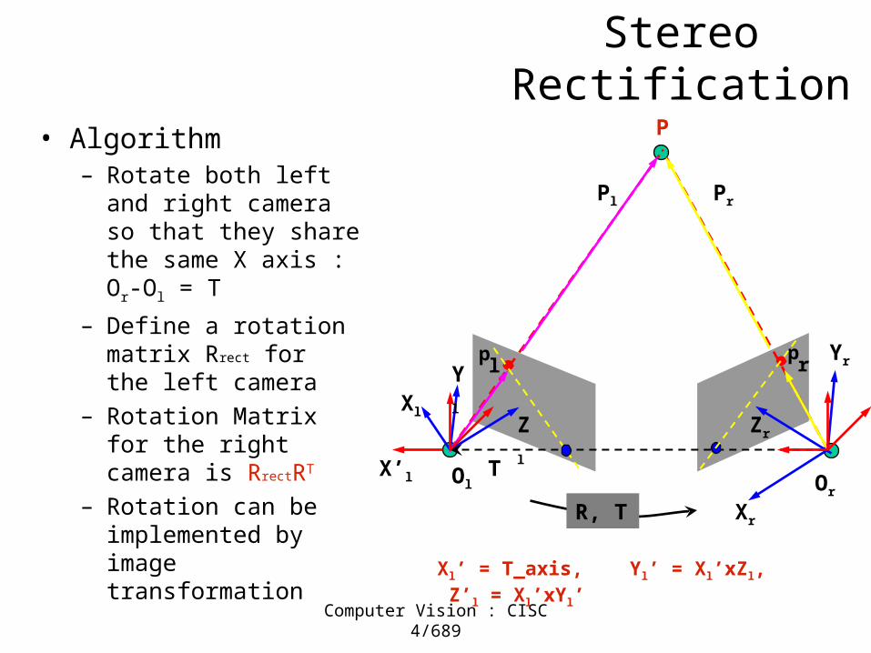
Stereo Rectification
• Algorithm– Rotate both left and right
camera so that they share the same X axis : Or-Ol = T
– Define a rotation matrix Rrect for the left camera
– Rotation Matrix for the right camera is RrectRT
– Rotation can be implemented by image transformation
pl
pr
P
Ol Or
Xl
Xr
Pl Pr
Zl
Yl
Zr
Yr
R, T
TX’l
Xl’ = T_axis, Yl’ = Xl’xZl, Z’l = Xl’xYl’

Computer Vision : CISC 4/689
Stereo Rectification
• Algorithm– Rotate both left and right
camera so that they share the same X axis : Or-Ol = T
– Define a rotation matrix Rrect for the left camera
– Rotation Matrix for the right camera is RrectRT
– Rotation can be implemented by image transformation
Zr
p’lp’r
P
Ol Or
X’r
Pl Pr
Z’l
Y’l Y’r
R, T
TX’l
T’ = (B, 0, 0),

Computer Vision : CISC 4/689Public Library, Stereoscopic Looking Room, Chicago, by Phillips, 1923

Computer Vision : CISC 4/689Teesta suspension bridge-Darjeeling, India

Computer Vision : CISC 4/689Mark Twain at Pool Table", no date, UCR Museum of Photography

Computer Vision : CISC 4/689Woman getting eye exam during immigration procedure at Ellis
Island, c. 1905 - 1920 , UCR Museum of Phography

Computer Vision : CISC 4/689
Stereo matching
• attempt to match every pixel
• use additional constraints

Computer Vision : CISC 4/689
A Simple Stereo System
Zw=0
LEFT CAMERA
Left image:reference
Right image:target
RIGHT CAMERA
Elevation Zw
disparity
Depth Z
baseline

Computer Vision : CISC 4/689
Let’s discuss reconstruction with this geometry before correspondence, because it’s much easier.
OOll OOrr
PP
ppll pprr
TT
ZZ
xxll xxrr
ff
T T is the stereo baselineis the stereo baselined d measures the difference in retinal position between corresponding measures the difference in retinal position between corresponding pointspoints (Camps)
Then given Z, we can compute X and Y.
Disparity:
xl,yl=(f X/Z, f Y/Z)Xr,yr=(f (X-T)/Z, f Y/Z)d=xl-xr=f X/Z – f (X-T)/Z
( -ve, +ve, referprevious slide fig.)

Computer Vision : CISC 4/689
Correspondence: What should we match?
• Objects?
• Edges?
• Pixels?
• Collections of pixels?

Computer Vision : CISC 4/689
Extracting Structure
• The key aspect of epipolar geometry is its linear constraint on where a point in one image can be in the other
• By correlation-matching pixels (or features) along epipolar lines and measuring the disparity between them, we can construct a depth map (scene point depth is inversely proportional to disparity)
View 1 View 2 Computed depth mapcourtesy of P. Debevec
Computer Vision : CISC 4/689
Correspondence: Photometric constraint
• Same world point has same intensity in both images.– Lambertian fronto-parallel
– Issues:
• Noise
• Specularity
• Foreshortening

Computer Vision : CISC 4/689
Using these constraints we can use matching for stereo
For each epipolar lineFor each pixel in the left image
• compare with every pixel on same epipolar line in right image
• pick pixel with minimum match cost
• This will never work, so:
Improvement: match windows
(Seitz)

Computer Vision : CISC 4/689
Aggregation• Use more than one pixel
• Assume neighbors have similar disparities*
– Use correlation window containing pixel
– Allows to use SSD, ZNCC, etc.

Computer Vision : CISC 4/689
Comparing Windows: ==??
ff gg
MostMostpopularpopular
(Camps)
For each window, match to closest window on epipolar line in other image.

Computer Vision : CISC 4/689
Compare intensities pixel-by-pixel
Comparing image regions
I(x,y) I´(x,y)
Sum of Square Differences
Dissimilarity measures

Computer Vision : CISC 4/689
Compare intensities pixel-by-pixel
Comparing image regions
I(x,y) I´(x,y)
Zero-mean Normalized Cross Correlation
Similarity measures

Computer Vision : CISC 4/689
Aggregation window sizes
Small windows
• disparities similar
• more ambiguities
• accurate when correct
Large windows
• larger disp. variation
• more discriminant
• often more robust
• use shiftable windows to deal with discontinuities
(Illustration from Pascal Fua)

Computer Vision : CISC 4/689
Window size
W = 3 W = 20
Better results with adaptive window• T. Kanade and M. Okutomi,
A Stereo Matching Algorithm with an Adaptive Window: Theory and Experiment,, Proc. International Conference on Robotics and Automation, 1991.
• D. Scharstein and R. Szeliski. Stereo matching with nonlinear diffusion. International Journal of Computer Vision, 28(2):155-174, July 1998
• Effect of window size
(Seitz)

Computer Vision : CISC 4/689
Correspondence Using Window-based matching
SSD error
disparity
Left Right
scanline

Computer Vision : CISC 4/689
Sum of Squared (Pixel) DifferencesLeft Right
Lw Rw
LI RI
),(),(
2
2222
)],(),([),,(
:disparity offunction a as differenceintensity themeasurescost SSD The
},|,{),(
:function window thedefine We
pixels. of windowsby ingcorrespond are and
yxWvuRLr
mmmmm
RL
m
vduIvuIdyxC
yvyxuxvuyxW
mmww
LwRw
),( LL yx ),( LL ydx
m
m

Computer Vision : CISC 4/689
Image Normalization• Even when the cameras are identical models, there can be differences in gain and sensitivity.• The cameras do not see exactly the same surfaces, so their overall light levels can differ.• For these reasons and more, it is a good idea to normalize the pixels in each window:
pixel Normalized ),(
),(ˆ
magnitude Window )],([
pixel Average ),(
),(
),(),(
2
),(
),(),(),(
1
yxW
yxWvuyxW
yxWvuyxW
m
mm
m
m
II
IyxIyxI
vuII
vuII

Computer Vision : CISC 4/689
Stereo results
Ground truthScene
– Data from University of Tsukuba
(Seitz)

Computer Vision : CISC 4/689
Results with window correlation
Window-based matching(best window size)
Ground truth
(Seitz)

Computer Vision : CISC 4/689
Results with better method
State of the art methodBoykov et al., Fast Approximate Energy Minimization via Graph Cuts,
International Conference on Computer Vision, September 1999.
Ground truth
(Seitz)