Credit: 1 PDH
19
Credit: 1 PDH Course Title: Pyrolysis in a Stage Scheme of Low-Grade Solid Fuel Gasification 3 Easy Steps to Complete the Course: 1. Read the Course PDF 2. Purchase the Course Online & Take the Final Exam 3. Print Your Certificate Approved for Credit in All 50 States Visit epdhonline.com for state specific information including Ohio’s required timing feature. epdh.com is a division of Cer�fied Training Ins�tute
Transcript of Credit: 1 PDH

Credit: 1 PDH
Course Title: Pyrolysis in a Stage Scheme of Low-Grade
Solid Fuel Gasification
3 Easy Steps to Complete the Course:
1. Read the Course PDF
2. Purchase the Course Online & Take the Final Exam
3. Print Your Certificate
Approved for Credit in All 50 StatesVisit epdhonline.com for state specific informationincluding Ohio’s required timing feature.
epdh.com is a division of Cer�fied Training Ins�tute

Chapter 4
Modeling of Pyrolysis in a Stage Scheme of Low‐Grade
Solid Fuel Gasification
Alexander Kozlov, Anatoly Levin, Denis Svishchev,
Vitaly Shamansky and Alexandre Keiko
Additional information is available at the end of the chapter
http://dx.doi.org/10.5772/67865
Abstract
This paper is concerned with the development of a model of wood pyrolysis in a screwreactor as the first stage of the multistage gasification process. In terms of design, the pilotpyrolyzer represents a recuperative heat exchangerwhere the heat carrier is represented byamixture of exhaust and recirculation gases. To prevent clinkering of particles and thermalinhomogeneities, screw-type transportation is used to transport fuel. In order to describekinetics of pyrolysis and transport of volatiles within the wood particles and their transi-tion to the gas phase, we carried out the studies using a complex of synchronous thermalanalysis. The original techniques for the interpretation of measurements were developedfor this complex, including the techniques for technical analysis of fuels and identificationof detailed kinetics and mechanism of pyrolysis. A detailed numerical modeling of pyro-lyzer was performed using the Comsol Multiphysics software, which makes it possible tooptimize the design and operating parameters of the pyrolysis process in a screw reactor.
Keywords: pyrolysis of low-grade solid fuel, multistage gasification, screw reactor,CFD modeling, thermal analysis
1. Introduction
One-stage processes of fuel gasification have been developed and thoroughly studied in Russiaand other countries throughout the twentieth century. They remain the basis for the creation anddesign of modern gasification equipment. Numerous studies showed that the one-stage gasifica-tion processes had already achieved the limit of perfection beyond which a considerableimprovement in their operating characteristics turned out to be impossible or unprofitable.
© 2017 The Author(s). Licensee InTech. This chapter is distributed under the terms of the Creative CommonsAttribution License (http://creativecommons.org/licenses/by/3.0), which permits unrestricted use,distribution, and reproduction in any medium, provided the original work is properly cited.

The gasification technology meeting the contemporary level of technology developmentshould correspond to the following criteria: (1) the gasifier should operate in automatic,mainly unmanned mode,(2) the gasifier operation should be stable and provide insignificantvariations in gas composition and flow rate that randomly occur over time,(3) it shouldproduce the minimum amount of liquid and solid waste,(4) the conversion process should be,if possible, little sensitive to changes in the properties of fuel biomass, that is, moisture contentand size of particles, and (5) the efficiency of converting fuel chemical energy into gas chemicalenergy should reach 80–85%.
The staged gasification technology meets the current technical requirements most completely.In the first stage of the process, the allothermal pyrolysis of biomass is organized usingproducer gas heat and exhaust gases of an engine unit. In this stage, the volatiles (gas and tar)are produced from the fuel. In the second stage, tar is decomposed under the action of heatedair and steam outside the fuel bed. Further, the formed steam-gas mixture reacts with thecharcoal in the third stage of the process.
2. A review of technologies for multistage solid fuel gasification
One of the first multistage gasifier was developed and patented by Antoine de Lacotte in the1940s [1, 2]. Oxidative pyrolysis took place in the upper part of fixed-bed reactor. Its gaseousproducts were taken from the space above the fuel bed and were sent to the external combus-tion chamber. The oxidation products of the tarred gas returned to the middle part of the fuelbed. One-third of these products were recycled in the pyrolysis stage and two-thirds wereinvolved in the coal-char gasification.
The obtained producer gas was very clean. Diesel internal combustion engine that used thisgas could operate without capital maintenance for 30 years [3].
The reactor similar to that designed by Antoine de Lacotte was proposed and patented by theGreek researcher Lamrpos Elefsiniotis [4]. He installed an air supply to the zone of oxidativepyrolysis in the shaft of a gasifier. Such an improvement makes it possible to control theamount of recycled gas coming from the combustion chamber [5]. A downside of the gasifiersinvented by de Lacotte and Elefsiniotis is the low efficiency of gasification, which is caused byhigh heat losses of the external combustion chamber. There is experience of accommodatingthis chamber inside the fuel bed [6]. In this case, heat coming from the chamber is used in thepyrolysis process and is not dispersed into the environment.
An interesting design of the multistage gasifier is proposed at the Technical University ofDenmark [7, 8]. It differs in that the stage of pyrolysis is separated and takes place in a separatescrew reactor whose duct is connected to the space above the fuel bed of the downdraft fixed-bed gasifier. In this space, part of pyrolysis gases is oxidized in the air blow. The combustionproducts come to the coal-char bed in the third stage of the process. A distinctive feature of thismultistage process is an active use of the producer gas heat and exhaust gases of the internalcombustion engine to heat the air blow and fuel in the screw pyrolyzer. Chemical efficiency ofsuch an allo-autothermal process reaches 93%, whereas in the autothermal conditions it does
Pyrolysis72

not exceed 75–80% [9, 10]. Moreover, the tar content in the unrefined gas is at the level of 15mg/nm3. Such gas can be used after its conditioning without additional cleaning. The TechnicalUniversity of Denmark has created a pilot plant Viking with a capacity of 20 kW (E). Its scaled-up version with a capacity of 200 kW (E) was implemented by the Weiss energy company inDenmark [11]. The Viking gasifier can be used to process fuel with a moisture content of up to30%. An additional screw reactor of the Weiss cogeneration plant intended for fuel dryingmakes it possible to convert biomass with a high moisture content (up to 60%). The successfuldesign of the Viking gasifier of the Technical University of Denmark inspired some teams todevelop and create similar plants. The Tomas Koch group (company TK Energy) simplified thedesign of the multistage gasifier by refusing from heating the screw reactor and using acomplex system of heat recuperation [12]. The air is blown to the pyrolyzer, thus providingpartial fuel combustion and operation of this reactor in the autothermal conditions. The pilotplant with a capacity of 2.3 MW (t) is established in the city of Gjol (Denmark).
A pilot plant similar to the Viking gasifier is manufactured by the team from the Institute ofQingdao (China) [13, 14]. They use pelleted biomass as a fuel, and the capacity of the plantmakesup 800 kW (t). The researchers from Shanghai Jiao Tong University (China) are developing amultistage gasifier with a capacity of 430 kW (f) for rice straw processing [15]. In the pyrolyzer ofthis gasifier, there is a fuel piston instead of screw machine. The researchers from the De CocodyUniversity are studying the work of a screw pyrolyzer embedded in the multistage gasifier [16].
However, the gasifier of the Technical University of Denmark and its analogs have one com-mon drawback. The high degree of biomass combustion is reached only for the sized fuel(chipped wood) prepared from solid species of wood. Such a fuel travels across the screwreactor with minimum destruction of particles, their crushing, and abrasion. Moreover, thechar bed in the third stage is effectively and stably gasified. There is no critical packing of thechar due to accumulation of coal powder and ash. The processing of the polyfraction orpelleted fuel is characterized by its considerable unburned amount. For example, the degreeof fuel carbon conversion in the gasifier of the Jiao Tong University makes up 75–80%. Massfraction of the lost char residue in the plant of the TK energy reaches 3–10%. Such a consider-able amount of unburned fuel leads to a decrease in the gasification efficiency and requiresmeasures for its further processing and utilization.
It is worth noting that to date none of the created plants has been scaled-up and reached thestage of commercial production despite its successful demonstration and a large amount ofpatents. It is also possible to state that the multistage gasification technology is developedmuch more slowly than the one-stage gasification technologies in the 1990s, even despite aconsiderable rise in the fossil fuel prices. There are technical difficulties hindering the wide-spread adoption of the technology, for example, (1) The number of operating parameters thathave an effect on the gasifier operation exceeds 11. This circumstance complicates optimizationof its operating conditions. (2) Low temperature of the third stage of the process preventscomplete combustion of the residual coal, thus leading to a decline in the gasification efficiencyand formation of a great amount of solid waste. (3) Operation of the modern gas-fired equip-ment (internal combustion engine, fuel cell, gas microturbine, etc.) requires additional removalof tars from gas to the level of 5–100 mg/nm3. Fine gas cleaning makes the technology much
Modeling of Pyrolysis in a Stage Scheme of Low‐Grade Solid Fuel Gasificationhttp://dx.doi.org/10.5772/67865
73

more expensive. Optimization of the second and third stages of the process is required toobtain an almost tar-free gas.
Thus, the development of a promising low-tonnage technology for staged gasification of woodbiomass should rest on a detailed research into thermal physics and chemical kinetics of theprocesses that occur in the equipment components.
In this research, we propose a new concept of staged gasifier, which suggests apart from theuse of a screw pyrolyzer the application of a hybrid fixed-bed reactor combining both down-draft and updraft processes. In this case, the tangential air supply is used, which providesgood mixing of pyrolysis gases with oxidizer, and, consequently, a high speed and completedecomposition of tar. Such an organization of the process makes it possible to gasify char notonly by the entrained flow of incomplete oxidation products of pyrolysis gas obtained in thefirst stage but also by heated air blow in the process countercurrent with respect to the fuelmotion. A block diagram of the developed multistage reactor is presented in Figure 1.
This paper presents the results of the research into the first stage of the multistage gasification,that is, allothermal wood pyrolysis in a screw reactor.
3. The methods for CFD modeling of wood biomass pyrolysis process
In the last years, there has been continuous evolution of the calculation models of pyrolysisplants. The research presented in [17] shows a mathematical description of the pyrolysis process.The authors devised a calculation model for the plant designed by them. The model consists of aset of stages of drying, thermal decomposition, interphase transitions, and cooling. Thus, thetotal duration of the wood feedstock decomposition τm process was represented by a set ofstages: heating τm, drying τd, thermal decomposition τtd, and cooling of char coal τс. Thismethod allowed the common model to be decomposed into submodels suitable for practicalimplementation that have different degrees of detail and respective form of equations (ordinarydifferential or in partial differential). A distinctive feature of this problem statement is the use of a
Figure 1. A block diagram of the plant for multistage gasification. Notations: 1—screw pyrolyzer heated by the internalcombustion engine (ICE) exhaust gases; 2—space above the fuel bed, producer gas combustion chamber; 3—a two-stagefixed-bed reactor.
Pyrolysis74

one-dimension representation of distribution of parameters in the space of pyrolyzer chamber.Change in the temperature of gas phase during its passing through the fuel bed was determinedfrom the following equation:
∂T1
∂τ¼ αΔTF
ðρcÞV � w∂T∂z
, ð1Þ
Solving Eq. (1) and equation of heat conductance for a solid fuel particle made it possible totake into consideration interphase heat exchange:
∂Tf
∂τ¼ 1
cpxg� ∂∂xf
xgλ∂Tf
∂xf
� �, ð2Þ
Moisture content in a fuel particle was determined by the authors [17] from the followingexpression:
dWdτ
¼βðpp � pÞ
ρV2, ð3Þ
Solving Eqs. ð2Þ and ð3Þ with the calculation of partial pressure made it possible to determinethe duration of a drying stage.
In the same way, the authors of [17] describe all the above-enumerated stages. The only assump-tion in their model was the absence of nonuniform distribution of parameters in the cross section.To verify their model, the authors of [17] made an experimental bench since in their case, as inmany other studies, verification of the constructed mathematical models is based on the uniqueexperimental data. This complicates a comparative analysis of the proposed approaches to theselection of the best description of the processes that occur in similar plants.
A more thorough study on partial gasification, on the basis of a numerical modeling andapplication of thermogravimetrical analysis, is presented in the recent publications [18, 19].For example, in the research [20] the authors applied a three-dimensional (3D) representationof the calculated region, which made it possible to more accurately determine variation intemperature profiles and gas motion velocities along the modeled furnace. Thus, a goodcorrespondence was achieved between the calculated data and the experimentally measuredprocess of fuel conversion. The model in [21] included the following equations:
r ¼ kfYNi¼1
cvi ¼ Af Tf expðEfa=RgTÞ
YNi¼1
cvi , ð4Þ
ρCp∂T∂τ
þ ρCpu∇T ¼ ∇∙ðk∇TÞ þQ, ð5Þ
�n∙ð�K∇TÞ ¼ εðG� σT4Þ, ð6Þ
ρ∂u∂τ
þ ρu∙∇u ¼ ∇∙ �pI þ μ�∇uþ ð∇uÞT
�� 2=3
hμð∇∙uÞI� þ FðaÞ, ð7Þ
∂ρ∂τ
þ ∇∙ðρuÞ ¼ 0, ð8Þ
Modeling of Pyrolysis in a Stage Scheme of Low‐Grade Solid Fuel Gasificationhttp://dx.doi.org/10.5772/67865
75

The analysis of the numerical modeling results that was carried out by the authors allowedthem to make a conclusion on the effect of heat generated in the gasification process on 3dtemperature fields and gas velocities inside the furnace. Thus, the detailed three-dimensionalrepresentation of an object in the numerical models is a necessary condition for the successfuldescription of complex adjoining processes that occur in the course of gasification.
A thorough analysis of mathematical models was presented in [20]. Large sizes of the plantsdo not allow us to construct highly detailed aerodynamic models. Therefore, special attentionis paid to the development of various closing relationships, in particular the equations ofkinetics of chemical reactions. As in the majority of other studies, these authors apply therelationships of the form
kv ¼ Avexp � Ev
RTs
� �, ð9Þ
rdry ¼ kvρYH2O, ð10Þ
One of the main parts in each similar research is the determination of a required list ofconditions that determine the relationship between the reaction rates and parameters of state,for example, temperature. The authors of [21] properly note that such a method can only beapplied to certain ranges of temperatures, whereas for high values (above 475K) it givesabsolutely unreal estimates of the rate of solid fuel drying. It is possible to conclude that theapplication of Eqs. ð9Þ andð10) without consideration of conservation laws naturally createsconditions for such problems to arise. Also, the authors of [21] indicate that the CFD modelsthat refer to a continuous porous medium are very attractive in terms of their possible imple-mentation.
Thus, the analysis of the existing studies shows the necessity to consider the detailed modelingof spatially distributed processes of heat-mass exchange, including the equations of kinetics ofchemical reactions, considering natural constraints that follow from the laws of conservation.The most promising seems to be the representation of heat-mass exchange equations in a 3Dform. In this case, the problem of a correct consideration of closing relationships in such astatement is not an exceptional characteristic of such detailed descriptions due to insufficientinformation on multi-parameter models that describe pyrolysis process. Thus, each new math-ematical model requires verification involving results of mufti-factor experimental studies.
4. Mathematical model
The geometry used for modeling a screw pyrolyzer is presented in Figure 2. The interior spaceis filled with a solid mass by 40%, which should provide easy circulation of the produced gasesaround the screw. The screw represents a spiral with a wall, 3 mm thick, which is wound on ahollow shaft. The interior space of the pyrolyzer with solid fuel and formed products isseparated from heating gases by a wall, 5 mm thick. The screw represents a geometricallycomplex structure. There are 11 complete spiral turns with a pitch of 139 mm on the hollow
Pyrolysis76

steel shaft. An external diameter of the spiral made up 139 mm, and the shaft diameter was38.6 mm. In the calculation, we took into account the body of the screw, shaft, and externalcoating. All the objects are constructed from cylinders. The construction of all these objectscaused the emergence of surfaces and regions of small size at the point of their intersection.The total number of components in the calculation mesh equals N. Optimal distribution andsizes of mesh cells were calculated using the Comsol Multiphysics Software on the basis ofcorresponding algorithms that ensure good convergence for the differential equations applied.The calculation mesh includes different number of cells:
For gas part, it includes hot gas from internal combustion engine and gas inside the screwabove the porous medium.
For a surface of solid elements, it includes all solid surfaces.
For the others, it includes solid volumetric parts such as screw, spiral, coating, and so on.
The Comsol Multiphysics Software is used as a simulation environment. Heat exchange in theprocess of pyrolysis is simulated considering physical properties (porosity, permeability, etc.)of the medium:
ρε
ðu∙∇Þ uε
� �¼ ∇∙ �pI þ μ
ε
�∇uþ ð∇uÞT
�� 2μ
3εð∇∙uÞI
� �� μ
kþ βFjuj þ
Qbr
ε2
� �uþ F, ð11Þ
Eq. ð11Þ differs from the model in [21] in the consideration of solid fuel porosity ε. In theequation, the changes in masses Qbr correspond to the gas masses formed in the course of thesolid fuel decomposition. Then, the equation of continuity has the following form:
∇∙ðρuÞ ¼ Qbr, ð12Þ
Heat exchange in pyrolyzer is calculated using the effective heat transfer coefficient:
Figure 2. Calculation mesh.
Modeling of Pyrolysis in a Stage Scheme of Low‐Grade Solid Fuel Gasificationhttp://dx.doi.org/10.5772/67865
77

ρCpu∙∇T þ ∇∙ð�keff∇TÞ ¼ Q, ð13Þ
In the area of high-temperature heads, we took into account the radiation heat transfer:
q ¼ с0ðT42 � T4
1Þ, ð14Þ
The equation of a diffusion barrier for the plane separating the porous solid body from the gasspace in the pyrolyzer is set as follows:
�nDs, i∇ci,u ¼ Ds, i
dsðci,u � ci, dÞ
�nDs, i∇ci,d ¼ Ds, i
dsðci,u � ci, dÞ
, ð15Þ
where ds is the barrier thickness, mm; Dsi is the diffusion coefficient, m2/s. In the calculations,we assumed a bed thickness of 5 mm and a diffusion coefficient of 1e�6 m2/s.
The boundary conditions chosen to solve the problem are as follows:
• An inlet temperature of fuel is 20�С;
• An inlet temperature of heating gases is 600�С;
• Avelocity of fuel flow in pyrolyzer is 1 mm/s;
• An inlet velocity of heating gases is 0.1–1 m/s.
5. Modeling results
5.1. Calculation of the fields of temperatures and gas flow velocities
The calculated fields of temperature, velocities, densities of media, streamlines, and otherderivative data were obtained by using the mathematical model of heat and mass transferprocesses in the screw pyrolyzers by using the Comsol Multiphysics software. Figure 3 pre-sents the calculated temperature values in the vertical sections along the pyrolyzer and also thevalues of formed gas flow velocity in the orthogonally directed planes. The calculation exam-ple demonstrates a sufficiently high degree of fuel heating and an adequate pattern of gas flowover the porous medium around the screw.
Figure 4 demonstrates successful heating of solid fuel providing the condition for its presenceat the temperature of above 500�С for 20 min at the fuel motion velocity of 0.001 m/s.
5.2. Parametric calculations
The parametric calculations are an essential part of the optimization study which is intendedfor determination of the most promising stepwise gasification technology of low-grade solidfuel. The parametric calculations can be made on the stable calculation model allowing thevariation of parameters in the solution, that is, boundary conditions, over a sufficiently widerange. The Comsol Multiphysics software makes it possible to calculate steady-state conditionsspecifying different laws of change in the boundary conditions.
Pyrolysis78

The developed calculation model of the screw pyrolyzer was tested on the basis of the follow-ing parametric studies:
A. the heating gas temperature at the pyrolyzer inletwas set from770 to 910Кwith a step of 20К;
B. the heating gas velocity at the pyrolyzer inlet was set from 0.1 to 0.9 m/s with an intervalof 0.2 m/s.
The results of testing (see Figures 5 and 6) confirmed the solution reliability and stability withpractically full convergence of numerical solutions and as a result the equal time spent on eachcalculation variant. The other variants of parametric studies are quite possible and seem to bethe least problematic from the viewpoint of numerical solution stability, since the current tasksin solving the numerical problems are aimed first of all at the achievement of stability to theinitial and boundary conditions.
The parametric calculations with the changing heating gas flow rate reveal an asymptote in thesolutions of temperature distribution; as far as starting with 0.3 m/s, the calculated values do
Figure 3. The example of calculations performed to determine the fields of temperatures and the motion velocities ofpyrolysis products. The heating gas velocity at the inlet section is w¼0.1 m/s.
Figure 4. The surface formed by the isotherm at 500�С.
Modeling of Pyrolysis in a Stage Scheme of Low‐Grade Solid Fuel Gasificationhttp://dx.doi.org/10.5772/67865
79

not change considerably at further increase of gas velocity values (Figure 5). This result enablesthe supposition about the existing optimal ratio between the working parameters of thedeveloped stepwise gasification scheme in the forthcoming optimization study.
Figure 5. Distribution of the temperature and its gradient in the pyrolyzer space for different heating gas flow rates.
Figure 6. Temperature distribution in the pyrolyzer space for different assigned values of heating gas temperature.
Pyrolysis80
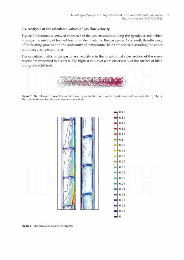
5.3. Analysis of the calculated values of gas flow velocity
Figure 7 illustrates a screwed character of the gas streamlines along the pyrolyzer axis whicharranges the mixing of formed fractions (steam, etc.) in the gas space. As a result, the efficiencyof the heating process and the uniformity of temperature fields are secured, avoiding the zoneswith irregular reaction rates.
The calculated fields of the gas phase velocity u in the longitudinal cross section of the screwreactor are presented in Figure 8. The highest values of u are observed over the surface of filledlow-grade solid fuel.
Figure 7. The calculated streamlines of the formed gases in the process of low-grade solid fuel heating in the pyrolyzer.The color indicates the calculated temperature values.
Figure 8. The calculated isolines of velocity.
Modeling of Pyrolysis in a Stage Scheme of Low‐Grade Solid Fuel Gasificationhttp://dx.doi.org/10.5772/67865
81

Markedly distinct velocity fields and as a consequence the diffusion coefficients characterizingtransfer of the gas phase from the porous mass to the free space can be formed for differentoperating conditions.
Figure 9 presents instantaneous values of gas flow velocities through the surface of the filledsolid fuel mass. The effect of heating gas temperature on the diffusion processes of formed gasyield was analyzed. The calculations show a negligible effect of the boundary conditions onmotion of the media in the region modeled by the diffusion thin bed. This fact suggestsfeasibility of using the constant coefficients to describe gas transition from the porous mediumto the space free for gas flow in the screw reactor. The maximum change in the velocity wasequal to ∼1% at the change of the heating gas temperature by 140 К at the pyrolyzer inlet.Thereby, the general distribution type of values in the velocity field did not change.
5.4. Application of the model for distribution of the formed substance concentrations
The validity of applying the stationary thermophysical dependences to the determination oftree properties in the pyrolysis process was analyzed. For this purpose, the temperature
Figure 9. The fields of gas flow velocity on the surface.
Pyrolysis82

gradient values in the fuel medium along the motion of solid particles were determined.Taking into account the velocity of fuel mass motion with respect to the pyrolyzer, it is possibleto compare the temperature gradient with the heating rates of experimental samples. Theconclusion confirmed feasibility of using the equations of chemical kinetics which were deter-mined at dT/dτ ¼ 30 K/min.
The applied approach to determination of the fields of concentrations of substances formed inthe course of substance reaction demonstrated satisfactory results of the calculation example(Figure 10). The highest concentration of steams formed during drying is observed in the zoneof intensive heating—in the initial part of the screw reactor, and as they flow along the reactorthe concentrations level off in the sections.
Because of inhomogeneity of heating, the steams formed in the process of solid fuel massheating substantially differ in concentrations on the initial part of the screw reactor (Figure 9).Figure 9 shows that the share of formed steams essentially depends on the operating factors.For example, more steam is formed inside the porous bed at the lower values of heating gastemperature at the pyrolyzer inlet. Because of the obvious nonphysical character of theseresults, the following explanation is advisable: in the available model of fraction formation,there are no constraints on the quantity of substances formed. As was mentioned in the work[21], the direct application of the Arrhenius-modified models leads to the similar effects. Thecorrect analysis of physical constraints requires more strict descriptions of the laws of concen-tration distribution which are based not only on the values of gas temperatures and velocities.One of the methods to solve this problem is to specify the initial concentration of associatedwater. Then, the equations describing change in concentrations will have the following form:
Figure 10. The calculated fields of steam concentrations.
Modeling of Pyrolysis in a Stage Scheme of Low‐Grade Solid Fuel Gasificationhttp://dx.doi.org/10.5772/67865
83

∇∙ð�D1∇c1Þ þ u∙∇c1 ¼ R1∇∙ð�D2∇c2Þ þ u∙∇c2 ¼ R1
,�
ð16Þ
where indices 1 and 2 correspond to concentrations of the steams and associated water,respectively.
5.5. Analysis of contribution of radiation heat transfer
Optimization calculations even for stationary mathematical models with concentrated pre-sentation of the description of processes need huge computational resources. It is not sur-prising that the numerical calculation of the three-dimensional fields of velocity,temperature, and others by using the server Xeon CPU E5606 (8 cores, 256 gigabyte of therandom access memory) of one condition required 24.5 working hours. Therefore, it istopical to reduce the mathematical model by the addition of assumptions allowing thenumber of equations to be decreased. From this point of view, the statement that the contri-bution of radiation heat transfer is unessential seems to be the most attractive. The identicaloperation conditions of the screw pyrolyzer were calculated considering the radiation heattransfer and without it. The calculation results (Figure 11) demonstrate invariability of thekey isotherm and the temperature field. The contribution of radiation heat transfer, whichamounted to less than 5% of the total energy exchange balance, was also estimated. If theradiation heat transfer is excluded from the general model, the computation time can sub-stantially be decreased from 24.5 working hours of the server with the indicated configura-tion up to 30–40 min.
At the same time, it should be noted that the conclusion about inessential contribution ofradiation heat transfer to the whole heat exchange contradicts the results of the work [21],which poses the question on deeper experimental study of this problem.
Figure 11. The calculation results of temperature field and isotherm position at T¼500�C by the models, which accountfor the radiation heat transfer (а) and without it (b).
Pyrolysis84

6. Conclusion
The model of heat transfer and aerodynamics of the pyrolyzer was developed for expressoptimization calculations. The temperature distribution in the pyrolyzer reactor was obtainedin a wide range of operating conditions. Moreover, it is confirmed that in the consideredthermal conditions the process of fuel conversion proceeds to completion. Inclusion of thekinetic block in the model of heat transfer made it possible to determine the concentrationfields of the formed substances (steam, etc.). Numerical experiments confirmed the possibilityfor the application of this model to optimization calculations.
Possible use of stationary experimental dependences for the determination of the rate ofchange in solid fuel density, yield of volatiles, and so on is shown for the range of consideredworking conditions. The results of parametric study demonstrated the existence of the asymp-tote for the optimal amount of heating gases which ensures the first stage of pyrolysis.
Acknowledgements
Results of the study were obtained using the Unique Scientific Plant “High-temperaturecircuit.” This work was carried out at the Melentiev Energy Systems Institute and financiallysupported by the Russian Science Foundation (project number 16-19-10227).
Nomenclature
A pre-exponent factor (1/s)
cp specific heat capacity of the gas mixture (KJ/kgK)
Dsi diffusion coefficient (m2/s)
E activation energy (J/mol)
F surface area (m2)
k kinetic rate constant (1/s)
P gas pressure (Pa)
p partial pressure (Pa)
Q heat transfer to wood chips by convection and radiation (W/m3)
R universal gas constant ∼8.314 (J/molK)
r reaction or process rate (kg/m3s)
T temperature (K)
τ time (s)
u velocity vector (m/s)
V volume (m3)
W moisture (%)
x coordinate (m)
Modeling of Pyrolysis in a Stage Scheme of Low‐Grade Solid Fuel Gasificationhttp://dx.doi.org/10.5772/67865
85

Author details
Alexander Kozlov*, Anatoly Levin, Denis Svishchev, Vitaly Shamansky and Alexandre Keiko
*Address all correspondence to: [email protected]
Melentiev Energy Systems Institute, Siberian Branch of the Russian Academy of Sciences,Irkutsk, Russian Federation
References
[1] Lacotte A. D. (1942). Procédé de gazéification totale des combustibles à haute teneur enmatières volatiles. Pat. FRT51403 19401120.
[2] Societe Distibois (1951). Method for the gasification of fuel having high contents ofvolatile matter. Pat. FRX648691 19391121.
[3] Kaupp A. (1984). Small Scale Gas Producer-Engine Systems. Vieweg Teubner Verlag.
[4] Elefsiniotis L. (2008). Three-Stage Gasifier, Fixed Bed, Which Has Buffer Zone of Gas-eous Flow Between Pyrolysis Zone and Combustion Zone. Pat. WO2007GR0001720070306.
[5] Antonopoulos I.S., Karagiannidis A., Elefsiniotis L., Perkoulidis G., Gkouletsos A.(2011). Development of an innovative 3-stage steady-bed gasifier for municipal solidwaste and biomass. Fuel Processing Technology, 92(12), 2389–2396. DOI 10.1016/j.fuproc.2011.08.016.
Greek letters
α heat transfer coefficient (W/m2K)
β mass transfer coefficient (kg/m2sPa)
ε porosity (–)
λ thermal conductivity (W/m K)
μ air viscosity (kg/ms)
p density (kg/m3)
σ normal stress tensor (Pa)
ω flow rate (m/s)
Subscripts
f fuel
g gas
s solid phase
Pyrolysis86

[6] Susanto H., Beenackers A. A. (1996). A moving-bed gasifier with internal recycle ofpyrolysis gas. Fuel, 75(11), 1339–1347. DOI 10.1016/0016-2361(96)00083-X.
[7] Henriksen U., Ahrenfeldt J., Jensen T. K., Gøbel B., Bentzen J. D., Hindsgaul C., SørensenL. H. (2006). The design, construction and operation of a 75kW two-stage gasifier. Energy,31(10), 1542–1553. DOI 10.1016/j.energy.2005.05.031
[8] Gøbel B., Henriksen U. B., Ahrenfeldt J., Jensen T. K., Hindsgaul C., Bentzen J. D., SørensenL. H. (2004). Status-2000 Hours of operation with the Viking gasifier. Grafica Lito.
[9] Hofmann P., Schweiger A., Fryda L., Panopoulos K. D., Hohenwarter U., Bentzen, J. D.,Kakaras E. (2007). High temperature electrolyte supported Ni-GDC/YSZ/LSM SOFCoperation on two-stage Viking gasifier product gas. Journal of Power Sources, 173(1),357–366. DOI 10.1016/j.jpowsour.2007.04.073.
[10] Svishchev D. A., Kozlov A. N., Donskoy I. G., Ryzhkov A. F. (2016). A semi-empiricalapproach to the thermodynamic analysis of downdraft gasification. Fuel, 168, 91–106.DOI 10.1016/j.fuel.2015.11.066.
[11] Bentzen J. D., Hummelshøj R., Henriksen U. B., Gøbel B., Ahrenfeldt J., Elmegaard B.(2004, January). Upscale of the two-stage gasification process. In World Conference andTechnology Exhibition on Biomass for Energy and Industry: Grafica Lito-Florence.
[12] Babu S. P. (2006). IEA Bioenergy Agreement Task 33: Thermal Gasification of BiomassWork Shop No. 1: Perspectives on Biomass Gasification.
[13] He T., Han D., Wu J., Li J., Wang Z., Wu J. (2015). Simulation of biomass gasification andapplication in pilot plant. Energy Technology, 3(2), 162–167.
[14] Wang Z., He T., Qin J., Wu J., Li J., Zi Z., Sun L. (2015). Gasification of biomass withoxygen-enriched air in a pilot scale two-stage gasifier. Fuel, 150, 386–393. DOI 10.1016/j.fuel.2015.02.056.
[15] Su Y., Luo, Y. (2009, March). Experiment on rice straw gasification in a two-stage gasifier. InPower and Energy Engineering Conference, 2009. APPEEC 2009. Asia-Pacific (pp. 1–4). IEEE.
[16] Fassinou W. F., Van de Steene L., Toure S., Volle G., Girard P. (2009). Pyrolysis of Pinuspinaster in a two-stage gasifier: Influence of processing parameters and thermal crackingof tar. Fuel Processing Technology, 90(1), 75–90. DOI 10.1016/j.fuproc.2008.07.016.
[17] Grachev A.N., Safin R.G. Valeev I.A. (2006), Pyrolysis of waste wood processing enter-prises. Chemistry and Chemical Engineering, 49, 10, 104–108.
[18] Wang G., Li, W., Li, B., Chen, H. (2008). TG study on pyrolysis of biomass and its threecomponents under syngas. Fuel, 87(4), 552–558. DOI 10.1016/j.fuel.2007.02.032.
[19] Han F., Meng A., Li Q., Zhang Y. (2016). Thermal decomposition and evolved gas analy-sis (TG-MS) of lignite coals from Southwest China. Journal of the Energy Institute, 89(1),94–100. DOI 10.1016/j.joei.2015.01.007.
Modeling of Pyrolysis in a Stage Scheme of Low‐Grade Solid Fuel Gasificationhttp://dx.doi.org/10.5772/67865
87

[20] Meng X., de Jong W., Badri F. S., Benito P., Basile F., Verkooijen A. H. (2012). Combustionstudy of partially gasified willow and DDGS chars using TG analysis and COMSOLmodeling. Biomass and Bioenergy, 39, 356–369. DOI 10.1016/j.biombioe.2012.01.032.
[21] Khodaei H., Al-Abdeli Y. M., Guzzomi F., Yeoh G. H. (2015). An overview of processesand considerations in the modelling of fixed-bed biomass combustion. Energy, 88, 946–972. DOI 10.1016/j.energy.2015.05.099.
Pyrolysis88