CREATIVE CONCEPTUAL DESIGN: EXTENDING THE SCOPE BY …
56
1 CREATIVE CONCEPTUAL DESIGN: EXTENDING THE SCOPE BY INFUSED DESIGN Offer Shai School of Mechanical Engineering, Tel Aviv University Yoram Reich School of Mechanical Engineering, Tel Aviv University Daniel Rubin School of Mechanical Engineering, Tel Aviv University CAD special issue on CD, in press Corresponding Author: Dr Offer Shai Faculty of engineering, Tel Aviv University Tel Aviv 69978 T: 972-640 6710 F: 972-640 7617 Email: [email protected] ABSTRACT Many methods that support human creativity by manual or computational means have been proposed in the past. They rely on the assumption that following a certain process of reasoning might lead to generating ideas considered creative. We start by defining creativity as a capability that enables the creation of systems that are patentable. We review the state-of-the-art of creative conceptual design and organize it with a framework. Subsequently, we present a method called infused design that guarantees generating design solutions by transforming systems and methods from remote disciplines. In many cases, these solutions would be deemed creative. Finding these systems and their transformations is done through a process based on the underlying discrete mathematical representation. This process is partially supported by a computer tool. We describe the method of infused design and illustrate its operation through part of the results achieved until now, including designing a new active torque amplifier system. We
Transcript of CREATIVE CONCEPTUAL DESIGN: EXTENDING THE SCOPE BY …

1
CREATIVE CONCEPTUAL DESIGN: EXTENDING THE SCOPE BY INFUSED DESIGN
Offer Shai School of Mechanical Engineering, Tel Aviv
University
Yoram Reich School of Mechanical
Engineering, Tel Aviv University
Daniel Rubin School of Mechanical Engineering, Tel Aviv
University
CAD special issue on CD, in press
Corresponding Author: Dr Offer Shai Faculty of engineering, Tel Aviv University Tel Aviv 69978 T: 972-640 6710 F: 972-640 7617 Email: [email protected]
ABSTRACT
Many methods that support human creativity by manual or computational means have been
proposed in the past. They rely on the assumption that following a certain process of reasoning
might lead to generating ideas considered creative. We start by defining creativity as a
capability that enables the creation of systems that are patentable. We review the state-of-the-art
of creative conceptual design and organize it with a framework. Subsequently, we present a
method called infused design that guarantees generating design solutions by transforming
systems and methods from remote disciplines. In many cases, these solutions would be deemed
creative. Finding these systems and their transformations is done through a process based on the
underlying discrete mathematical representation. This process is partially supported by a
computer tool.
We describe the method of infused design and illustrate its operation through part of the
results achieved until now, including designing a new active torque amplifier system. We

2
further demonstrate its benefits through other examples. We discuss the relation of infused
design with other creativity or design methods and conclude with future developments of the
method.
“A well-directed imagination is the source of great deeds.”
Chinese proverb
Keywords: creativity; conceptual design; graph representation; collaborative design; design
support systems; framework; analogy
1 INTRODUCTION
Conceptual design is a central stage in product design; it determines the principles that
govern the product. Decisions made in this stage have major impact on the final product quality,
cost, and market success (Pahl and Beitz, 1996). But even high quality conceptual design
leading to high quality products does not guarantee product success. If a company wishes to
capture or maintain its market leadership, it must do better than that; it must develop
breakthrough or radical innovations (McDermott and O’Connor, 2002).
Our position in this paper is that creative conceptual design (CCD) is central to developing
innovative products. Therefore, studying and improving CCD is an important undertaking.
However, creativity and innovation are elusive concepts; to some it is mysterious. There are
more than 80 definitions of creativity in the literature (Dasgupta, 1994). A common definition of
creativity is that creativity is the ability to generate new useful things that are characterized by
being original and imaginative. The meaning of these properties is open to interpretations;
therefore, for the purpose of this study we adopt a particular definition: CCD outputs a
description of a device or a system that is or judged to be patentable. This definition
concentrates on the engineering functionality of products rather than on their industrial design or

3
esthetics. We also focus on determining the principles that govern the product rather than a
precise description of its structure and its detailed embodiment.
In section 2, we review the state-of-the-art of creative conceptual design. We provide a
framework that helps organize previous work on the subject and helps locate areas of missing
work. Rather than being exhaustive in the review, we mention representative studies that allow
spanning the space of studies. A complete review deserves a separate study.
In section 3, we describe a method called infused design (ID) that provides a basis for
extending creative conceptual design along several dimensions. Our method is independent of
designers’ personality, cognitive style, or other factors; it enables radical creativity
demonstrated by generating designs that were not conceived before, by studying and exploiting
designs from seemingly unrelated disciplines. It is built on a foundation that allows focused,
partially computable, well-directed imagination.
Section 4 provides several examples that demonstrate these extensions. The discussion in
section 5 elaborates on ways to integrate ID with other methods and further improve the support
for creative conceptual design. Section 6 concludes the paper.
2 REVIEW OF CREATIVE CONCEPTUAL DESIGN
Creativity in general and in design or in conceptual design has been a topic of major attention
over the years. Given the fascination with creativity and its foreseen economical value, it is no
surprised that many researchers tried to understand it, find factors that correlate or enable
creativity in different settings, and develop methods to enhance creativity. To illustrate, Smith,
(1998) summarized 172 idea generation methods which could be perceived as the first and most
critical part of creative design. The purpose of this section is to provide a brief overview of past
research in relation to product design, organize it in a framework, and use this framework to
identify interesting research topics.

4
2.1 A framework for organizing CCD studies
The framework defines a multidimensional space that allows classifying creativity studies.
Based on six dimensions:
1. Actor complexity,
2. Product complexity,
3. Cognitive style or trait,
4. Cognitive process,
5. Problem structure and,
6. Design processes, practices, culture, or tools.
The first dimension addresses the actor complexity reflected by the number of actors
performing the design, their setup, e.g., whether collocated or distributed, etc. This dimension
varies from a single designer to a distributed team. Single designers have been the subject of
many studies on creativity. However, in contemporary product development practice, many
creative solutions arise from collaborative work. This ‘single vs. many’ dichotomy echoes
product complexity dimension that starts with a single device composed of few building blocks
and ends with systems composed of many building blocks.
Studies of single designers have often dealt with the cognitive style or trait of people
whereas the studies related to the creativity of groups have dealt with the cognitive style pool of
group members. Cognitive style could be viewed as cognitive structure; its complement is the
cognitive process which is the process used by designers to address design problems. The
structure and process dimensions really use nominal scale; however, we turn them roughly into
ordinal by ordering the approaches from least to most creative style and least to most creative
process support.

5
Beside the contribution of designers to creative product design, the design context has major
influence on the outcome. The context could be characterized by the product complexity
whether a single device or a complex system; the problem structure (e.g., problem definition)
which could invite or deter creativity; and the design processes, practices, culture, or tools
available in the designers organization. These dimensions correspond to the designers’ aspect
dimensions. Together, the six dimensions span the space of studies on many product design
topics including CCD.
2.2 Review of CCD studies
In dealing with creative conceptual design, our focus is on the findings of different studies
and how they help us improve the state of creative conceptual design. More precisely, our
interest is in the ability to design environments that foster creative conceptual design. The
following review describes studies that span the space of possibilities; it is definitely not
exhaustive. Some studies are roughly located in the framework shown in Figure 1.
2.2.1 Creative designers
The easiest way to influence the creativity of a design environment is to select creative
designers that have greater chances to generate creative products. This however requires
connecting two perspectives on creativity: creativity as trait or style and the product of creative
acts. Measuring traits has been based on various psychological tests.
In most real world product development projects, teams are necessary to address the
interdisciplinary nature of designs. But in relation to creativity, working in teams is often seen
as a way to enhance creativity by forming social creativity (Fischer, 2000). Paulus (2000)
suggested that when teams member differ in their background knowledge, their diverse
perspective might lead to broad coverage of skills and constructive conflict. When such
background knowledge overlap, analogies could emerge more easily and creativity could

6
improve (West, 2002). Without sufficient overlap, diversity could lead to communication
problems, hampering the chance for creativity (West, 2002). Other models that explain the
working of creative design teams have been proposed (e.g., Leifer, 1998; Fischer et al., 2005)
suggesting that communication means between designers, whether implemented in processes,
tools, or settings are key to success. Such communication is often mediated by the creation of
‘boundary objects’ – concrete representations of the product that team members create, share,
and evolve (Fischer et al., 2005; Subrahmanian et al., 2003).
In order to realize these ideas, diverse creativity tests have been developed for designers and
teams. A variation on the Myers-Briggs Type Indicator test (Briggs Myers and McCaulley,
1985) was developed and used in creativity studies (e.g., Stevens et al., 1999). The latter test
was further developed to allow composing creative product development teams based on
diversifying their knowledge, styles, or roles (Wilde, 2004). Creativity was measured by the
winning of a particular design competition.
2.2.2 Cognitive strategies, methods, and tools (designers perspective)
Although cognitive style is commonly perceived as fixed, cognitive strategies could be
altered by training (Ripple, 1989) and tools or methods could be implemented and used
effectively. As previously mentioned, idea generation is fundamental to creativity in general and
creative conceptual design, specifically. Given some statistics that on the order of 3000 raw
ideas are required to generate one successful product in the market (Stevens and Burley, 1997),
this task requires serious support. Many methods have been developed to assist in idea or
concept generation including brainstorming (Osborn, 1953), TRIZ (Altshuller, 1988), or ASIT
(Horowitz, 1999). There have also been numerous attempts to create creative programs or
support human creativity by computational means. These range from support systems based on
analogical reasoning (Qian and Gero, 1996; Goal, 1997), systematization of knowledge based,
7
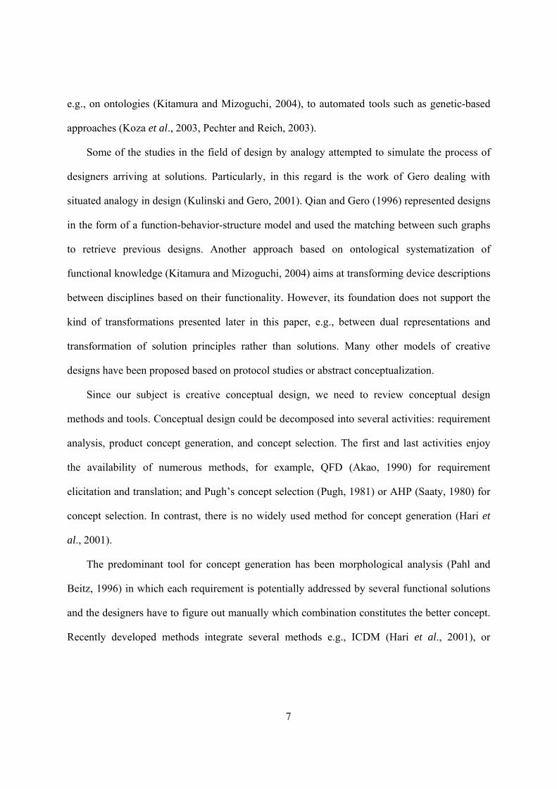
e.g., on ontologies (Kitamura and Mizoguchi, 2004), to automated tools such as genetic-based
approaches (Koza et al., 2003, Pechter and Reich, 2003).
Some of the studies in the field of design by analogy attempted to simulate the process of
designers arriving at solutions. Particularly, in this regard is the work of Gero dealing with
situated analogy in design (Kulinski and Gero, 2001). Qian and Gero (1996) represented designs
in the form of a function-behavior-structure model and used the matching between such graphs
to retrieve previous designs. Another approach based on ontological systematization of
functional knowledge (Kitamura and Mizoguchi, 2004) aims at transforming device descriptions
between disciplines based on their functionality. However, its foundation does not support the
kind of transformations presented later in this paper, e.g., between dual representations and
transformation of solution principles rather than solutions. Many other models of creative
designs have been proposed based on protocol studies or abstract conceptualization.
Since our subject is creative conceptual design, we need to review conceptual design
methods and tools. Conceptual design could be decomposed into several activities: requirement
analysis, product concept generation, and concept selection. The first and last activities enjoy
the availability of numerous methods, for example, QFD (Akao, 1990) for requirement
elicitation and translation; and Pugh’s concept selection (Pugh, 1981) or AHP (Saaty, 1980) for
concept selection. In contrast, there is no widely used method for concept generation (Hari et
al., 2001).
The predominant tool for concept generation has been morphological analysis (Pahl and
Beitz, 1996) in which each requirement is potentially addressed by several functional solutions
and the designers have to figure out manually which combination constitutes the better concept.
Recently developed methods integrate several methods e.g., ICDM (Hari et al., 2001), or
8
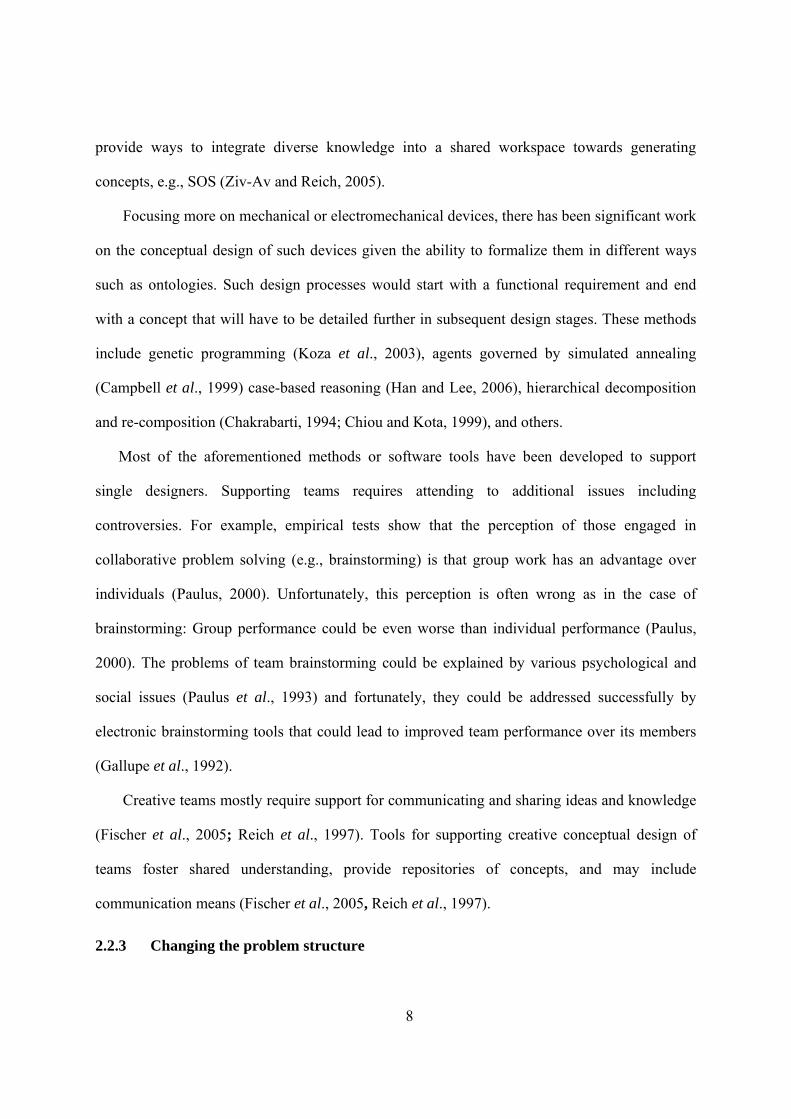
provide ways to integrate diverse knowledge into a shared workspace towards generating
concepts, e.g., SOS (Ziv-Av and Reich, 2005).
Focusing more on mechanical or electromechanical devices, there has been significant work
on the conceptual design of such devices given the ability to formalize them in different ways
such as ontologies. Such design processes would start with a functional requirement and end
with a concept that will have to be detailed further in subsequent design stages. These methods
include genetic programming (Koza et al., 2003), agents governed by simulated annealing
(Campbell et al., 1999) case-based reasoning (Han and Lee, 2006), hierarchical decomposition
and re-composition (Chakrabarti, 1994; Chiou and Kota, 1999), and others.
Most of the aforementioned methods or software tools have been developed to support
single designers. Supporting teams requires attending to additional issues including
controversies. For example, empirical tests show that the perception of those engaged in
collaborative problem solving (e.g., brainstorming) is that group work has an advantage over
individuals (Paulus, 2000). Unfortunately, this perception is often wrong as in the case of
brainstorming: Group performance could be even worse than individual performance (Paulus,
2000). The problems of team brainstorming could be explained by various psychological and
social issues (Paulus et al., 1993) and fortunately, they could be addressed successfully by
electronic brainstorming tools that could lead to improved team performance over its members
(Gallupe et al., 1992).
Creative teams mostly require support for communicating and sharing ideas and knowledge
(Fischer et al., 2005; Reich et al., 1997). Tools for supporting creative conceptual design of
teams foster shared understanding, provide repositories of concepts, and may include
communication means (Fischer et al., 2005, Reich et al., 1997).
2.2.3 Changing the problem structure

9
The product complexity is usually given by the problem definition, e.g., designing a device
or a complex system are two different things. Such differences could be addressed by matching
them with actor complexity. But for a particular problem, if we allow the development teams to
modify it or if the problem is sufficiently open, then the available opportunity for creativity
could be realized (Leifer, 1998; West, 2002).
2.2.4 Organizational culture, practices, and tools
Designers never work in isolation from a context. They are often part of an organization
with knowledge, culture, and managerial practices. It is easy to kill creativity by focusing on
productivity and efficiency (Amabile, 1998). However, practices that promote cultural values
that foster creativity could exist or be nurtured (Amabile, 1998), and with the right strategies for
uncertainty reduction including outsourcing and working with users (Von Hippel, 1986), and
project management tools and attention to the people aspect, radical innovation could be
supported (McDermott and O’Connor, 2002).
This dimension provides opportunity to see the interaction between some of the dimensions
in the framework because its manipulation usually requires attention to other dimensions. There
are several examples of successful integrations.
In the context of real demanding design tasks, teams created systematically (Wilde, 2004),
that are coached (Reich et al., 2006b) in a particular development process demonstrate
consistently creative capabilities leading to creative products (Leifer, 1998). Creative team
members that follow a well defined process led to better development performance in real
projects (Stevens et al., 1999). Finally, implementing creativity tool such as ASIT in the context
of a comprehensive design methodology helped design teams achieve creative performance in
demanding tasks (Reich et al., 2006a). All these examples are far from perfect. There is much to
be learned from them to further improve creative conceptual design of teams.

10
2.2.5 Analysis and future work
When mapping CCD studies onto the six-dimensional framework by assigning the value 1
to most simple and 9 to most complex values, this data could be analyzed. We perform this
analysis using repertory grids (Kelly, 1955). Repertory grids represent objects of any kind (e.g.,
CCD studies) with different dimensions that might have different scales (e.g., discrete, ordinal).
These grids could be analyzed and reveal insight into the space of objects; they could also assist
in directing further exploration by pointing to additional objects and dimensions that could be
added to the grid. Consequently, they could be used as research tools for review purposes and
others, see examples in (Reich, 2000; Reich and Kapeliuk, 2005; Reich et al., 2006b).
Figure 1 shows a partial analysis of a grid performed by the repertory grid tool WebGridIII
(Gaines and Shaw, 1996). The figure shows a clustering of the dimensions (top right) and of the
studies (bottom right). The first reveals that there are correlations between the complexity of the
product and the complexity of the organizational processes used to develop it; more creative
designers might use diverse strategies or methods; and more open problems are solved by more
complex team structures. All these three correlations are familiar from practice but, more studies
need to be mapped onto the framework to obtain better correlations. The preliminary
correlations between the CCD studies are quite intuitive: studies (1), (2), and (3) are quite
similar; (4) and (5) are similar; and (7) and (8) are similar. The method we present in this paper,
ID, is quite different from the rest, thus it expands the scope of existing studies.

11
Figure 1: Preliminary analysis of the creative conceptual design framework. The numbers
in the legend represent the following data points:
(1) TRIZ-like methods: a single designer, knowing this method, could solve device-level problems,
without needing organizational support
(2) Use of genetic-based algorithms: automatically generating multidisciplinary devices
(3) Research studies of a single designer performing a lab experiment over a short period of time
(e.g., hours)
(4) Small group of university students, organized in creative teams; with minimal knowledge of
design tools, but with significant organizational culture and support, doing a complex device
design whose problem statement could be altered (Leifer, 1998)
(5) Small group of high school students; working in teams, with minimal technical knowledge but
knowledge of a structured design process and tools; with considerable organizational support,
doing a complex device design whose problem statement is fixed (Reich et al., 2006a)
(6) Brainstorming: group of designers works to create new ideas using the method and
organizational cultural support
(7) Studies of real industrial projects where experienced teams followed various structured
organizational processes (e.g., Stevens et al., 1999; McDermott et al., 2002)

12
(8) Practical goal: Practices for supporting industrial creative teams through design tools and
organizational processes in breakthrough innovation projects
(9) Infused design
Much more work is required to further understand creativity in general and CCD
specifically. This work ranges from specific topics to overall integration of the various
dimensions. An arbitrary collection of specific topics include: comparing between different idea
generation methods (e.g., McKoy et al., 2001), moving techniques for creative design of devices
to systems; creating diverse teams with sufficient overlap to support communication (West,
2002), or maintaining a balance between creativity and effectiveness in development projects.
Along with particular issues, controversies related to creativity tools need to be further studied
and clarified. For example does brainstorming support group creativity or not and if it does, in
which context? Or could creative cognitive style of people be altered?
Methodological issues in the study of creativity also exist. Given opinions that almost all
creativity arise in social interaction (e.g., Fischer et al., 2005), how much can be learned from
few protocols of single designers? (Dorst and Cross, 2001). Another issue involves the ability to
extract useful information for practical implementation from laboratory or even educational
settings such as in (Leifer, 1998, Reich et al., 2006a). Finally, the multiple perspective for
studying creativity need to be sorted out to for allow cross fertilization (Sternberg, 2005).
A crucial issue for engineering that relates to the methodological issues is transforming the
results of creativity studies into actionable knowledge that could impact practice; for example,
using all this knowledge to inform the development of new creativity tools or support systems
(Hewett, 2005) and understanding which type of computer tool might be appropriate for
different design contexts (Lubart, 2005).

13
Finally, more theoretical work is needed to understand the phenomena of team CCD. We
previously mentioned models of single designers, and there are models of team CCD (e.g.,
Leifer, 1998; West, 2002), where each addresses particular and sometimes overlapping
dimensions. There is also a theory that places creativity at its core (i.e., C-K theory, Hatchuel
and Weil, 2003). However, much better understanding of the interaction between the multiple
framework dimensions is needed towards achieving creative conceptual designs in practice.
3 THE PROCESS OF INFUSED DESIGN
Shai and Reich (2004a) presented the ID process model (see later, Figure 4) further extended
it in (Shai et al., 2005). This section presents a revised version of the latter model.
3.1 Notation
In order to explain the nature of problem representation in ID we define a notation. In the
notation,
• Capital letters denote sets or classes of problems or models
• Small letters denote single items or instances of classes
• Superscripts denote different types of models or representations
• Subscripts denote different sub-parts of a system
Any design team possesses a particular disciplinary perspective D consisting of:
• T - a set of alternative disciplinary terminologies (e.g., different ways to describe force, rod,
connection, support, area that are used in structural engineering or resistor, capacitor, diode,
current, voltage, and amplifiers in electrical engineering).
• M - the type of the combinatorial representation that governs the creation of a model (some
of these types are more common than others within the perspective D ).

14
The team can use a particular piece of knowledge and some primitive concepts to transform
an initial problem information p into a model m described with a particular terminology t . The
model and its terminology are denoted by the pair ( )tm, . This pair is called the representation of
the problem. The model of the problem m would subsequently be solved by some method sm .
We proceed to describe the different ID activities with this notation.
Dual representationsGeneral-than relation between representationsRepresentation of a discipline represented by Engineering discipline
Legend
Mechanisms
Planetary gear systems
Hydraulic systems
Determinate trusses
Dynamical systems
Indeterminate beams
Pillar systems
Static lever systems
Indeterminate trusses Electrical
circuits
1 2 3 4
RGR Resistance Graph
Representation
1 2 3 4
1 2 3 4
PLGR Potential Line Graph
Representation
1 2 3 4
PGR Potential GraphRepresentation
LGR Line Graph
Representation 1 2
3 4
FGR Flow Graph
Representation
1 2 3 4
FLGRFlow Line GraphRepresentation
Figure 2: Map of graph representations, their interrelations, and association with engineering
systems (Shai and Reich, 2004b)
The representations that are the foundation of ID are discrete mathematical models, called
graph representations; they include Resistance Graph Representation (RGR), Potential Graph
Representation (PGR), Flow Graph Representation (FGR), and others. For example, a FGR
representation of a truss is shown in Figure 15 of the appendix and a PGR representation of a
linkage is shown in Figure 16. In the FGR representation, m is the graph model, Figure 15(b), and
t is the terminology used to describe such models including: joint = vertex, edge = rod, unit
vector for each edge = rod orientation, etc.

15
These representations can represent diverse systems, e.g., RGR is the isomorphic
representation of both electrical circuits and indeterminate trusses (Shai, 2001b). These
representations and their relations (see Figure 2), such as the duality between PGR and FGR
allow transforming automatically one representation to others connected to it (Shai, 2001a).
Shown in the appendix, such transformation could be done automatically. Since these
transformations guarantee that each representation has the same behavior, the automated part of
ID is provably correct. This is in contrast to other methods such as design by analogy or design
based on ontology which do not guarantee that the transformation process between disciplines
will be successful.
3.2 ID process
Design starts with a written, verbal, problem description, abstract idea, or in some other
unspecified manner. The initial information is limited, uncertain, and ill defined. Problem
formulation is a process of creating a product specification, ps , from the initial problem
information, p . Problem formulation is quite informal and involves (1) making assumptions
about the focus of the problem and the importance of different aspects; (2) information
consolidation from diverse structured and unstructured sources; and (3) authoring the
specification. The product specification might include, in addition to the verbal description,
drawings, computer models, physical objects, and other available information. It could be
incomplete or even inconsistent, thus requiring future revisions.
The system being developed could be composed of many components j , mj ,,1 K= , each with
its own representation i , ni ,,1K= . We denote component j in its representation i with ( )ij
ij tm , .
These indices are independent since one component might have several representations at
different times for different purposes; furthermore, several components might have the same

16
representation. ID can proceed by integrating the different components representations ( )ij
ij tm , ,
mj ,,1 K= into subsystems with a single representation ( )11 , ++ nj
nj tm that could be assembled into
the complete system or product representation ( )11 , ++ nn tm as shown in Figure 3.
( )11
11 t ,m ( )n
mnm t ,m
( )1n1n t ,M ++
( )1n1
1n1 t ,m ++ ( )1n
m1n
m t ,m ++
( )1n1n t ,m ++
(1) (1) (2)(2)
(3)Commonrepresentation
Intermediaterepresentations
Originalrepresentations ( )i
jij tm ,
( )ii tM ,
(1)
( )nn tM ,( )11 , tM
( )ββ tM ,( )αα tM ,
Figure 3: Transforming diverse subsystems representations into a common system representation
(Shai and Reich, 2004a)
In the figure, the dashed boxes refer to representations such as RGR, FGR, or PGR that are
depicted in Figure 2; the solid boxes denote specific models of the components. The integration is
accomplished by identifying a common representation composed of model type and
terminology ( )11 , ++ nn tM that can accommodate all the original representations. Step (1) in Figure 3
shows this move from the original representations, through intermediate representations,
e.g., ( )αα tM , , to the common representation. Subsequently, the original models ( )ij
ij tm , ,

17
mj ,,1 K= are transformed into the common representation ( )11 , ++ nj
nj tm (step 2); and the models
can be combined into the complete system model ( )11 , ++ nn tm (step 3).
To better illustrate Step (1), consider the following example. Members of the
multidisciplinary team start by using their customary disciplinary model and terminology for
each discipline ( ) ( )nn tMtM ,, 11 K , e.g., PGR for mechanisms and FGR for static systems, see
appendix for examples. In order to integrate all the disciplinary representations they need to
search for one common representation ( )11 , ++ nn tM that accommodates all the original
representations. This representation must have known mathematical relation such as duality or
generality with the original representations. This search could be done without considering the
particular problem at hand. It is performed following relations found in previous studies that are
depicted in Figure 2. For the particular example, according to Figure 2, PGR, FGR and RGR
could serve as the common representation because PGR and FGR are dual and because RGR is
more general to both. The search is therefore trivial; furthermore, it could be automated.
The common representation ( )11 , ++ nn tM allows borrowing solutions or solutions methods from
different disciplines. For example, suppose one of the problems p of one practitioner is found to
be very difficult in his discipline (see Figure 4).
Step (1): The problem is modeled by the practitioner in 0m , a model of the model type 0M .
We can denote this process by 0mpD→ , clarifying that 0m is created from p by some
disciplinary perspective D .
Step (2): A common representation ( )11 , ++ nn tM is found between the problem representation
and other disciplinary representations. The problem model is automatically transformed
from 0m to 1m and onwards, while modifying the terminology.

18
Step (3): A reference discipline is selected and the problem model could be automatically
transformed into model 3m described by its disciplinary terminology 3t .
Step (4): Team members who are experts in that discipline can now locate design solutions 3S
for the problem and model it in the disciplinary representation.
Step (5): Once the solution is modeled, it could be automatically transformed in the opposite
direction, resulting in solutions representations to the original problem 0S .
Step (6): To complete the process, this representation has to be implemented in the original
discipline by the practitioners.
Originalproblem
representation( )00 t ,m
( )11 t ,m
( )11 t ,M ( )22 t ,M
( )3, S33 t ,m
( )22 t ,m
oSReference
problemrepresentation
other equivalent intermediaterepresentations at the commonabstract level
( )00 t ,M ( )33 t ,M
(2)
(2)
alternativepaths
alternativepaths
(3)
(1) (6)
Formal, computable operations
Manual operations
(4)
(3)
(5)
Active torque amplifier
device
inω
inTinout ωω =
inout TkT ⋅=input output
Figure 4: Infused design process model (modified from Shai and Reich, 2004a)

19
Figure 4 makes explicit the formal and computable operations of ID which involve
transformations between graph representations and the manual operations of ID which deal with
transformations between physical/disciplinary models and graph representations,
There are several decision points in the ID process that are critical to understand and
appreciate. These decision points appear in steps (1), (2), (3), (4), and (6) and are denoted by
multiple arrows:
Step (1): When representing the problem, there could be several options, i.e., different graph
representations with which to represent the engineering system; which of the options
should be selected?
The choice of representation often depends on the level of detail required. This is a general
modeling problem in any domain and in particular in engineering. For example, a structure
could be modeled as a truss if its members’ connections are flexible or as a frame if they
are stiff. Since this is the first step of the process, it influences the difficulty and success of
the process.
Moreover, different representations enable revealing different properties of the engineering
system. For example, if we deal with kinematical system, choosing PGR enables to reflect
the properties of the linear velocities of the system, while choosing PLGR enables to
concentrate upon the angular velocities.
There could also be different modeling choices at different levels of granularity. For
example, a lattice boom of a crane could be modeled as a frame to analyze its internal
forces or as a bar to analyze the complete crane. In the present complexity of the
infrastructure of ID (see Figure 2), it is possible to check multiple representations of a
device.

20
Step (2): After a problem is represented, there could be alternative paths in which it could be
transformed into intermediate representation ( )11 , ++ nn tM , which one should be selected?
The obvious answer is trying all representations. Since the representations are discrete
models, the process could be automated so that only computational resources are necessary.
As seen in Figure 2, currently most disciplines could be transformed to one (e.g., static
lever systems) up to three representations (e.g., mechanisms). Therefore, it is quite easy to
try all the possibilities. Even if multiple paths are selected in the hierarchy, the
combinations do not grow significantly; the hierarchy is limited in size so that the number
of paths through different representations is rather small.
Minimizing the paths traversed is not a necessary goal. Intermediate representations have
built in knowledge that could be used to shed a new light on the present problem, as was
done in the process of revealing the equimomental line in statics (the dual of instant center
from kinematics) using the duality between FGR and PGR and the duality between PLGR
and FLGR (Shai and Pennock, 2006).
Step (3): Another issue is which reference discipline should be selected in order to search for a
solution?
The answer is similar to the previous question. The preferred solution is trying as many
solutions as possible. Therefore, the more reference disciplines are explored, the higher the
potential to find good results. Given the size of the present hierarchy, the number of options
is small enough to be familiar to a team of practitioners so that they can make a judgment
based on their collective expertise how to prioritize the reference disciplines. However, in
the future, as we try increasingly complex designs and as more disciplines are added and
since this approach is founded on discrete mathematics, this step could be automated.

21
Step (4): This step exhibits the same line of reasoning about alternative representations as in
Step (1). In addition, another situation arises when a device does not easily transform into
the graph representation. For example, a transistor is a device with three interfaces thus
cannot be added as a primitive to any graph representation which comprises devices with
two interfaces. Electrical engineers encounter this problem when they use graph
representation to solve analog circuits. They had to create a model of a transistor that is
composed of other components with two interfaces each. This model is quite complicated
and introduced difficulties for solving circuits yet it is necessary. It is plausible that new
devices that are introduced in some discipline would have to be modeled approximately to
allow their representation by graphs.
Step (6): When translating the solution back, there might be (parts of) devices that do not have
immediate mapping in the source domain. Realizing these fragments of graph
representations in the source domain requires domain knowledge to find the physical
principle that could govern the implementation as well as an effective embodiment. For
example, realizing current source controlled current (ideally) from electronics in mechanics
is not trivial since there is no such primitive design available. Consequently, a subsystem
that replicates the current source controlled current (CSCC) behavior needs to be designed
and implemented in order to map electrical circuits that include CSCC into solutions for
problems in mechanisms.
Each of these decision points becomes a source of creativity. While ID does not help in this
act, it certainly focuses the attention on the precise points where creativity is required. This
focusing is illustrated in section 4.1 that deals with creating a new concept in engineering that is
being employed for devising a new mechanical amplifier device.

22
4 EXAMPLES
This section provides several examples that demonstrate the way ID extends CCD. The first
example shows how a new patentable device is developed by ID and consequently demonstrates
the basic premise of the approach.
The second example shows how devices from diverse disciplines are derived from a single
device in a way that guarantees the functionality of the new devices. This demonstrates breadth
of the method: once a new principle is discovered, it could be used to generate diverse creative
devices. The equivalence between these diverse disciplines, which is made explicit in Figure 2,
allows transforming knowledge from diverse disciplines to assist in solving a particular problem.
As more perspectives or disciplines are available through more participants, better solutions
could be devised.
The third example shows that not only can ID support creative design of devices; it can also
support creative formation of new knowledge. In the fourth example, this new knowledge in turn,
extends the scope of ID by bringing downstream concerns into the conceptual stage.
4.1 Design of an Active Torque Amplifier Device
This example demonstrates how ID is used to generate a new device that is patentable. This
establishes the basic claim of the method.
4.1.1 Function
There are many mechanical devices that generate an amplified input at the output. Examples
include gear systems and levers. In each of these devices, there is a conservation law that governs
the device behavior. In a gear system, the angular velocity could be amplified but the power
remains constant, therefore, the external moment is reduced. In a lever, the force is amplified but
the energy remains the same so that the distance traveled is reduced. Suppose we wanted a device

23
that amplifies the input moment and maintains the angular velocity. This statement is the problem
definition p. Figure 5 presents a schematic description of the function of the required device. This
model 0m , expressed by the domain terminology 0t (angular kinematics), is the translation of the
problem definition p. Obviously, to realize such a device we would need an external power
source to support the additional power required at the output. This need will be satisfied
automatically when we transform a solution from any discipline.
Active torque amplifier
device
inω
inTinout ωω =
inout TkT ⋅=input output
Figure 5: Functional description of the proposed device
Therefore, the device possesses at least two interfaces: the input shaft and the output shaft.
The properties are as follows:
1. The angular velocity at the output shaft is kept equal to the angular velocity supplied at the
input shaft.
2. The torque exerted by the output shaft is equal to the torque applied at the input multiplied
by a constant k. Constant k is the pre-designed structural property of the device, and can
reach values of several hundreds in accordance with the requirements of the selected
application.
Consider an example of the active torque amplifier with amplification ratio 100=k . Suppose
one rotates the input shaft with angular velocity of sec1rad . By property 1, the output shaft will
also be forced to rotate with the same angular velocity. Suppose that in order to rotate the load
connected to the output shaft with this angular velocity, a torque of Nm100 is to be exerted on it
by the output shaft. Thus, according to property 2, the torque to be applied to the input shaft
would equal to NmNmk 11001 =⋅ . To balance the torque difference, external engine would have

24
to supply the remaining Nm99 . As a result, despite the heavy load connected to the output, one
can easily rotate it with the desired angular velocity by applying a small torque. On the other
hand, due to the constant ratio between the input and the output torques, one still “feels” the
output resistance at the input.
Such a mechanism could be useful for many practical applications that would value the
advantage of the “feeling” property in addition to the amplification. Practical applications include
a working tool, such as a precise screwdriver, or drill that enables performing manually
controlled rotational motion, while the device supplies any power necessary to overcome
resistance at the output; various rescue equipment tools; and a new concept for a power steering
wheel mechanism, depicted in Figure 6.
B
EThe active
torque amplifier
C
Steering
Car wheels
Car engine
Figure 6: A simplified principle sketch of the new concept of the power steering
wheel mechanism employing the active torque amplifier
In the proposed concept, the steering wheel is connected to the input of the active torque
amplifier, while its output is connected to the differential rotating the car wheels. The external
source shaft of the active torque amplifier can be connected through a proper transmission to the
car engine or to an additional dedicated engine, such as the one used today for the hydraulic
steering wheel. This way the torque applied by the driver upon the steering will be amplified and

25
applied to rotate the wheels to the desired angle. Such a concept for the power steering offers a
number of advantages:
• No need for special pumps and hydraulic fluids to operate the power steering wheel.
• The “feeling” property allows the driver to feel higher resistance at the output, thus it will
be harder for him to rotate the steering at higher velocities.
• No need for electronic control components.
• Relatively small number of parts, which are easy and cheap to manufacture.
4.1.2 The process used to develop the device
The device was designed through the following steps that correspond to the steps in Figure 4.
Step (1): Representing the problem
Figure 5 is a visual representation of the desired device. A formal representation of the
problem in the mechanism discipline could be:
Design a device S that has the following two interfaces:
Interface Role w T
1 Input win Tin
2 Output wout Tout
Step (2): Exploring alternative paths
The next step is finding alternative paths that may lead to solutions in different disciplines.
From Figure 2 we observe that there are multiple paths that could be explored from the
mechanisms representation to various intermediate representations including:
1. Mechanisms → PGR → FGR. The latter involves transforming between dual
representations, see appendix for this example.

26
2. Mechanisms → PGR → FGR → RGR. The latter involves transforming between one
representation to its generalization.
3. Mechanisms → LGR.
Each of these intermediate representations, iM , may expose new opportunities. In particular,
the LGR representation allows access to the following disciplines: planetary gear systems, pillar
systems (through FLGR), electrical circuits (through PGR), and static lever systems and
determinate trusses (through FGR). Within this representation, designers can find representations
of all the devices known to date. If one of these representations possesses the function modeled
by ( )01, tm , the search for solutions has been successful.
Steps (3) and (4): Selecting reference disciplines
As mentioned in the previous subsection, from each visited intermediate representation, there
are reference disciplines that could be accessed. Each such reference discipline could be a source
for solutions. Even if solutions are represented at intermediate representations, the device in the
reference representation contains additional knowledge beyond its representation. In our case, out
of all existing devices, designers could detect two that match the required functionality. This
could be done automatically by matching the formal representations of the devices. In this case,
we merely need to find 2 interfaces in each device that match the definition in step (1). The
complexity of this matching increases with the number of interfaces. Performing it efficiently for
large devices remains a topic for future research.
1. The electronic transistor that could be accessed through the PGR representation. In this
case, the model ( )01, tm would be translated into the PGR representation, 2M with its own
terminology 2t (i.e., potential difference, ...). From the model, the translation would lead to
model 3m of type 3M in the terminology 3t of electrical circuits.

27
2. The hydraulic Valvistor that was developed by Vickers (1993) that could be accessed
through the RGR representation.
Seemingly, we have two solutions that could be used to develop creative devices. However,
these devices are isomorphic. This means that if their models are translated into the same model
type 4M of RGR through a sequence of translations, these models would be isomorphic from a
graph theory perspective. Consequently, we select to continue the design with the transistor
knowing that transforming the transistor back to the original domain involves only one
intermediate representation.
Step (5): Finding alternative paths for transforming solutions back
This step is similar to step (b). In the particular example, only one path has been explored
from electrical circuits ( )33, tm back to PGR ( )22 , tm , see Figure 7. The figure shows the
correspondence between the parts of the transistor and the graph in this discipline. This
translation could be done automatically but presently is done by hand.
B C
E
(a) (b)
Figure 7: Finding one alternative path. (a) the transistor modeled in ( )333 ,, Stm ; (b) the
translation of ( )333 ,, Stm into ( )222 ,, Stm of PGR
Step (6): Implementing the solution principles in the source domain

28
When transforming devices from one reference discipline into another through the
intermediate representations, new opportunities are opened for the designer since for the same
device representation, different devices can be constructed. For the given design case, the device
from the reference discipline is one dimensional (electronics) while the source domain consists of
a number of dimensions. For the given design problem, two options were applied: linear and
angular dimensions. The availability of multiple options demonstrates one of many potential
applications of the proposed technique. These options could be codified for each case and
maintained for future reference; for example, when moving from one dimensional space into
multidimensional such as kinematics, the translation could be implemented into linear or angular
dimensions.
The designer can transform one device from the target domain ( )333 ,, Stm and get several
devices ( )01
00 ,, Stm , … ( )000 ,, nStm that are all isomorphic to the same device. This translation is
done manually and involves creativity in embedding the elements and relationships that appear in
the graph into 3-dimensional physical media. Each such device gives a different perspective and
new insight on the new device and even on the reference device. For example, the reported
invention was found to possess a novel self controlling mechanical principle that has never been
reported in the literature. The mechanical engineers in our group had difficulties in capturing and
understanding the idea underlying this device and understanding how it works. The possibility of
constructing two devices, one linear (Figure 8) and the other angular (Figure 9), enabled
understanding its behavior using the former which also helped implementing the latter to become
a practical application in industry. We skip the details of the linear device and elaborate next on
the particular implementation and operation of the final solution.

29
B
E
C
Figure 8: Linear Active force amplifier schematic drawing
This proposed product is a one of a number of new concepts that have been developed in the
last decade through the same technique and are about to be introduced to industry.
4.1.3 Structural and behavioral description of the device
Figure 9 presents a schematic drawing of the proposed device. The device is comprised of
only three solid parts: B, C and E and its performance does not require any additional control or
electronic components. As the device has been obtained by transforming knowledge of the
electronic transistor, there is a complete correspondence between the behavior of the
abovementioned parts and base, collector and emitter of the transistor. Part B is the input shaft,
part E is the output shaft and part C is the shaft connected to the external power supply with high
angular velocity. The rotation axis of B is connected to E by a screw thread. When B is rotated at
angular velocity ω , the screw thread causes E to displace towards C and to attach to it. When C
and E are attached, the friction between them causes E to rotate as well. When E reaches an
angular velocity higher than that of B, the screw thread will cause E to displace right and to
detach from C. Thus E will constantly attach itself to C in order to keep its angular velocity equal
to that of B.

30
Figure 9: Active torque amplifier schematic drawing
The torque transmission from C to E is determined by the corresponding friction coefficient
and thus is constant subject to the material properties and the form of the interface surfaces.
Furthermore, one can see from the sketch that the output torque equals the sum of the torques
applied to B and to E. Figure 10 summarizes the four stages of the working principle of the active
torque amplifier.
Accordingly, the function of the new mechanical device can be outlined by two relations: (a)
the angular velocity of the output shaft is kept equal to the angular velocity of the input shaft and
(b) the torque applied by the output shaft is equal to a the torque applied upon the input shaft
multiplied by a high constant coefficient. This function maps the function of the electronic
transistor, where the voltages upon the base and the emitter are kept approximately equal, while
there is a high constant ration between the base and the emitter currents.

31
a. Disengaged mode: Rotation of B causes E to move
towards C
b. Push mode: C causes E to rotate through
friction
c. Free rotation mode: When E starts to rotate faster
than B, it moves left and disengages from C.
d. Push mode: When E starts to rotate
slower than B, it moves right and returns
to push mode
Figure 10: The four stages of work of the active torque amplifier
The above principle description covers the one direction of action of the active torque
amplifier (say counter clockwise). In order for the device to handle the rotation in both directions
by means of the same principle, a number of additional simple parts are to be added to the device,
but the principle of work remains the same.
A prototype of an active torque amplifier with amplification ratio of about 100 was
constructed and successfully tested at the Mechanism Laboratory of Tel-Aviv University (Figure
11).

32
Figure 11: Active torque amplifier device constructed in the Mechanism
Laboratory at Tel-Aviv University
4.2 Equivalent systems
This example expands on the previous one by showing that the process exemplified above
can be replicated to diverse domains, leading each to new creative designs. Shown in Figure 12,
is a simple known electrical rectifier circuit that is transformed into three different disciplines: a
gear system, a hydraulic system, and a structure, to obtain the corresponding rectifying function.
33
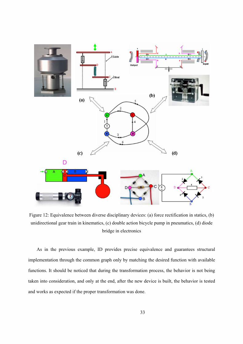
Figure 12: Equivalence between diverse disciplinary devices: (a) force rectification in statics, (b)
unidirectional gear train in kinematics, (c) double action bicycle pump in pneumatics, (d) diode
bridge in electronics
As in the previous example, ID provides precise equivalence and guarantees structural
implementation through the common graph only by matching the desired function with available
functions. It should be noticed that during the transformation process, the behavior is not being
taken into consideration, and only at the end, after the new device is built, the behavior is tested
and works as expected if the proper transformation was done.

34
Moreover, even faulty behavior is transformed. To clarify this issue, let us examine the
behavior of the diode bridge and the unidirectional gear train when the input source is wrongfully
connected, for example at the output. In the diode bridge, when the input source is located
between junctions C and D and the positive potential is connected to D then nothing will happen
in the circuit and zero voltage will be measured at the input (now output) port (junctions AB).
But, connecting the negative potential to D will result in a short circuit. For the unidirectional
gear train, one can easily verify that the output (link 4) could rotate clockwise without resistance
while the driving link (link 1) remains still; while trying to rotate link 4 counterclockwise is not
possible since the system is in a locked position.
Comparing any two systems appearing in Figure 12 will show correspondence
between the behaviors both in correct and faulty modes.
4.3 Extending creativity: adding knowledge to devices and systems
This example shows that ID enables transforming not only devices, but also concepts, ideas,
and methods thus yielding new methods and concepts in other engineering disciplines. The
following example demonstrates the process of deriving a new concept in statics, termed – ’face
force,’ which was transformed from kinematics using the route described in the map (Figure 13).
Presently, these derivations are done manually.
As appears in Figure 13, the representations that correspond to mechanisms in kinematics are
PGR (Potential Graph Representations) while the representations corresponding to determinate
trusses in statics are FGR (Flow Graph Representations) which are proved to be dual graphs, thus
every linkage is dual to a determinate truss and vice versa. This equivalence between the systems
yielded equivalence between the concepts in these two engineering domains. For instance, the
relative linear velocity of a link was proved to be the counterpart of the force acting in the
corresponding rod in the dual determinate truss. Applying this equivalence enabled to reveal a

35
previously unknown counterpart of the absolute linear velocity of a linkage joint in statics, which
is a new type of force variable termed 'face force' (Shai, 2002). The face-forces act in each face of
the static system and possess the properties of potential, similarly to a mesh current variable in
electrical circuits. Figure 13(a) depicts a four bar linkage superimposed upon its dual truss. It is
highlighted in the figure, that the absolute linear velocity of each revolute joint is identical to the
face force acting in its corresponding face of the dual truss, shown in Figure 13(b).
(a) The original linkage and its superimposed dual truss
(b) The dual truss
Figure 13: The kinematic system (linkage) and its dual static system (determinate truss)
4.4 Addressing downstream concerns: finding locking positions of linkages
This example demonstrates how the discovery of the face force allows the development of a
tool that aids the design process. Knowing the locking positions in advance is essential for
engineers for diverse applications, such as for toggle mechanisms (Sclater and Chironics, 2001),
for deployable structures and for preventing entering to such positions when a continuous motion
is needed. In application that locking is undesired, it could emerge after the detailed design or
even production since it was not foreseen to occur. This situation would require product redesign.
P
2'
3'
P
2' 3' A
B
FA
FB
1
2 3

36
The new concept – face force and its further developments – can help the designer avoid being in
such situations.
The essence of a linkage being in a locking position is that the driving link cannot move, thus
it exerts force, which produces internal forces in the links of the linkage. Therefore, the problem
of finding the locking configurations becomes a problem of finding the configurations, where the
forces in the links, produced by the driving link, can be found in static equilibrium. Since the face
force possesses properties of both forces and potentials, it is possible to choose arbitrarily a face
force for each face of the linkage so that they define a feasible configuration of the forces in the
links. Since the forces in the links are vectors, the inclinations of the links can be determined
from the force diagram.
Figure 14(a) shows the topology of a mechanism for which arbitrary face forces are assigned as
shown in Figure 14(b), which in turn, define the directions of each link in the locking position.
Analysis of this result, together with tools transformed also form statics, which due to length
limitation of the paper are not described, enables the engineer to characterize the configuration in
which the linkage will be in a locking position. In this case, as shown in Figure 14(c), the
engineer can characterize that when the intersection points of the links (or their continuations): 2
and 4; 5 and 9; and 6 and 8 are collinear, then the linkage is in a locking position and there are
internal forces in all the links.
It is important to notice that this characterization applies to any configuration of the linkage, i.e.,
lengths, angles etc. Furthermore, the design tools used in this example were derived through the
transformations between statics and kinematics.

37
(a) The topology of the linkage
(b) The arbitrarily force diagram
(c) The corresponding locking position of the mechanism
Figure 14: Example of finding the locking configuration through the face forces
5 DISCUSSION
5.1 Scope of infused design
ID (Shai and Reich, 2004a, b) leads to generating creative products by transforming products
from one discipline to another. One of the advantages of ID or creativity is that during the
transformation process, no analysis procedure is used, and the properties of new engineering
systems are revealed only after the final step, when the device has been constructed from the
graph. Furthermore, the mappings in ID are founded on discrete mathematics and are not
heuristic. This means that transformations between representations could be automated. Another
major difference between ID and analogy-based approaches is that ID does not rely on surface
structural similarity but on various formal principles. It could map domains that are similar but
also domains that are dual in the mathematical sense. This allows obtaining surprising results.

38
Altogether, as partially demonstrated, there are significant consequences to what could be done
with ID compared to other methods.
The ID process presented here extends the previous by including also transformations
between the formal representation of the concept and the representation of the physical
embodiments (e.g., Step (6), Figure 4). In the case of the mechanical amplifier, the embodiment
of the representation in physical material involved experimentation and creative thinking focused
on how to implement a physical principle in the desired domain. We could foresee additional
devices arising from additional creative embodiments presently unknown. The value of ID is in
focusing designers on the truly creative steps while allowing for mechanizing the rest.
ID brings all knowledgeable engineers to be fruitful participants in any design project. Its
foundation serves as a common language that is continuously extended with additional concepts
(e.g., face force). Furthermore, the available designs and those that are continuously created with
ID serve as ‘boundary objects’ that together with the new concepts expand and enhance
communication channels between multidisciplinary professionals. There is nevertheless, a
difference between the contributions of different engineers for different projects. For example, in
designing the mechanical amplifier, the mechanical engineer has the central role. Steps (a), (b),
and (d) are all part of the mechanical engineer contribution. In particular, step (d) can be
completed solely by one that has significant mechanical design expertise.
It turns out that ID subdivides design activities into those that could be formalized and done
automatically and those that embody significant creative design expertise (Figure 4). This
subdivision allows creating a true collaboration between decision support systems for design and
design professionals, where each perform the most suitable task. This issue is further discussed
later.

39
Although not shown here, ID could be used to represent thus generate multidisciplinary
devices (Shai and Rubin, 2003) and complex devices from simpler ones by connecting them and
condensing the result (Gorodetsky, 2004). This allows addressing complex functionality
requirements since for specific complex functionality; it is unlikely that equivalent devices would
exist in other disciplines.
5.2 Integration with other methods
ID could be integrated with other design or even creativity methods whether they address
device or system level perspectives. We illustrate several such integrations here. Among the
illustrations, we select TRIZ and axiomatic design as they could be perceived as complementary
methods (Lee and Ahn, 2006). Axiomatic design could be used to define and analyze multi
functional systems but lacks synthesis assistance and TRIZ could be used to address few
functions but it lacks system level perspective. ID could integrate with each and both and deliver
added value.
TRIZ-like methods. ID and creativity methods such as TRIZ or ASIT are natural candidates
for complementing each other. ID could get help from such methods in the following way. If no
solution for a given problem exists in other disciplines that could be transformed by ID, there
could be at least two solution paths. First, if by considering functionality, there is a similar but
not equivalent device in one discipline, it could be transform to the desired domain and TRIZ
could be used to improve it to the desired functionality. Second, if no similar device exists, a
suitable device could be created using methods such as TRIZ. The effort spent on this process
could be amortized by sharing the new concept with all other disciplines.
ID could also support TRIZ-like methods. If TRIZ is used to design multifunctional system,
TRIZ would be best at assisting the design of few-function devices. ID could be used to integrate
40
simple devices (even if they are multidisciplinary) by combining their graph representations and
condensing them.
Axiomatic design. ID could also be used with evaluative methods such as axiomatic design.
For example, it is currently known from electrical engineering that there are only two
conceptually dissimilar rectifying devices. If one is using axiomatic design to design a system
and rectifying function is required, in could be realized by one of the available concepts. Multiple
function systems requirements could also be matched directly with available solutions or
synthesized from simpler devices and condensation. For example, it could be difficult to create an
efficient device for two functions in one discipline. The complex device could be transformed
into another discipline, condensed there, and the result transferred back to the original discipline
(Dagani, 2004). Axiomatic design could guide the condensation toward minimizing information
content while maintaining the independence of the functional requirements as much as possible.
System-level tools. Since ID can be used on devices or systems whose behavior could be
formalized by graph representation, it could benefit from integration with general system-level
synthesis tools such as SOS (Ziv Av and Reich, 2005). SOS uses existing building blocks to
compose systems that address diverse customer and manufacturer’s objectives. The building
blocks could be devices or systems that perform desired functions. In case the overall product
concept created by SOS is not satisfactory, focused search could be done to replace sub-optimal
devices with better solutions derived by ID. More complex search for better building blocks
could be done to replace multiple building blocks with better devices created by ID. Note that an
integration of ID with TRIZ and axiomatic design could work as well with SOS in the same way.
Genetic-based approaches. A final example of integrating ID with device-level perspective
comes from genetic programming approaches and simulated annealing that have been used to
generate mechatronics and other devices from functional descriptions (e.g., Koza et al., 2003).

41
These methods work by evolving representations of the designed product until its behavior
approximately matches the desired function. ID can be used to model mechatronics and more
complex multidisciplinary product concepts. Its integration with generative approaches could be
used to generate devices from scratch (Pechter and Reich, 2003), thus providing means to enrich
the base for other uses of ID.
5.3 Future work
In the future, we intend to develop a computational system that would support all the formal
steps of ID, relieving designers to focus on the essence of the creative activities. In addition, once
a solution is created in a particular discipline, its representation would be recorded with its
engineering knowledge that is not expressed in the graph representations (e.g.,
manufacturability). When the hierarchy grows and more problems and solutions are introduced, it
will be necessary to support this process with an information system. Case-based reasoning could
be used to index and retrieve solutions (Reich and Shai, 2000); indexing might benefit from
functional ontology at the level of systems (Kitamura and Mizoguchi, 2004). Altogether, a
system such as n-dim (Reich et al., 1999) is an excellent candidate for integrating all these
support mechanisms. Note that although we might use such indexing mechanism which is
heuristic, once a solution is found, it is transformed back into the original problem automatically
as discussed above.
We intend to demonstrate the creative conceptual design of complex system level products
that could include multidisciplinary components or subsystems. This demonstration would be
based on the ability of the underlying representation to represent multidisciplinary systems (Shai
and Rubin, 2003).

42
We further intend to explore integration with other design methods such as those described
before. In doing so, it would become clearer what are the benefits and limitations of the various
methods and how they could work better together.
The utility of ID is derived not only by its mechanisms but also by the disciplines that get
connected by the graph representations (shown in Figure 2). We intend to continue and establish
additional connections with other disciplines to leverage their collective knowledge.
5.4 The framework after introducing ID
Not only designers need to be creative, researchers developing creativity methods need to be
creative as well. Therefore, it is important to continually, propose, develop, and test new methods
that extend the scope of CCD. ID extends the scope of CCD in several ways (see also Figure 1).
In the actor aspect of the framework, ID displays several new properties. ID works well with
a single designer who is familiar with the foundation of the method and working with a
repository of past designs; it works better with a group of people from different disciplines where
each is in charge of her disciplinary designs; and it could also work with several designers from
each discipline providing different experiences regarding physical embodiments and other issues
outside the scope of ID. The use of ID creates common language and invents new conceptual
terms (e.g., face force) that could subsequently be used to enrich communication. Consequently,
ID can be used and it supports diverse user compositions. ID has been used by designers without
attention to cognitive style. We believe that traditionally “less creative” designers could still
derive significant benefit by using ID.
In relation to the product context of the framework, ID makes also significant contribution.
The most unique aspect of ID is the capability to transfer knowledge between disciplines. As
demonstrated by the face force and the locking device examples, such transfer provides
significant value to designers. This capability adds another dimension to the framework.

43
Otherwise, ID is quite independent of the problem structure and organizational processes and
culture.
6 CONCLUSIONS
This paper has two main contributions. The first contribution presented a framework for
organizing studies on CCD and reviewed representative studies that span this space. The result of
this review is a list of research needs classified into several categories. This framework can serve
to focus on many potential studies, for example, there could be many studies that check the
interaction between any two dimensions.
The second contribution is the presentation of ID as a method for supporting CCD. The ID
process was reviewed and revised compared to its previous presentations, including decision
points along the process, and the parts that could be automated. Several significant examples
were presented to show the value of the revised ID method and its future potential. We also
presented ways in which ID could integrate with other tools. In doing so, we follow the
aforementioned hypothesis that combing diversity of skills, styles, or knowledge could engender
creativity. Similarly, the integration of diverse CCD tools, could lead to the emergence of new
interesting capabilities. We concluded the discussion on ID with a list of future research issues.
Together, the framework and ID provide new ways at looking at CCD.
ACKNOWLEDGMENTS
Part of this research was supported by the Fleischman Research Grant. We thank the
reviewers for their comments on the draft of this paper.
REFERENCES
[1] Akao Y. (ed) (1990) Quality Function Deployment, Productivity Press, Cambridge,
MA.

44
[2] Altshuller G., Creativity as an Exact Science, (Translated by A. Williams), Gordon and
Breach, New York, 1988.
[3] Amabile T. M., How to kill creativity, Harvard Business Review, 76(5):76-87, 1998.
[4] Balabanian N. and Bickart T. A., Electrical Network Theory, John Wiley & Sons, New
York, 1969.
[5] Briggs Myers I. and McCaulley M. H., Manual: A Guide to the Development and Use
of the Myers-Briggs Type Indicator, Palo Alto, CA, Consulting Psychologists' Press, 2nd
Edition, 1985.
[6] Campbell M. I., Cagan J., and Kotovsky K., A-Design: An agent-based approach to
conceptual design in a dynamic environment, Research in Engineering Design,
11(3):172-192, 1999.
[7] Chakrabarti A., An approach to functional synthesis of solutions in mechanical
conceptual design. Part I: Introduction and knowledge representation. Research in
Engineering Design, 6(3):127-141, 1994.
[8] Chiou S.-J. and Kota S., Automated conceptual design of mechanisms, Mechanism and
Machine Theory, 34(3):467-495, 1999.
[9] Chironis N. and Sclater N., Mechanisms, Linkages and Mechanical Controls, McGraw
Hill, NY, 2001.
[10] Dagani N., Systematic Conceptual Engineering Design Using Graph Representations,
MSc thesis, The Iby and Aladar Fleischman Faculty of Engineering, Tel-Aviv
University, Tel Aviv, 2004.
[11] Dasgupta S., Creativity in Invention and Design, Cambridge University Press, New
York, 1994.

45
[12] Dorst C. H. and Cross N. G. (2001) Creativity in the design process: co-evolution of
problem-solution, Design Studies, 22:425-437.
[13] Fischer G., Social creativity, symmetry of ignorance and meta-design, Knowledge-
Based Systems Journal, 13(7–8):527–537, 2000.
[14] Fischer G., Giaccardi E., Eden H., Sugimoto M., and Ye Y., Beyond binary choices:
integrating individual and social creativity, International Journal of Human–Computer
Studies, 63:482–512, 2005.
[15] Gallupe R. B., Dennis A. R., Cooper W. H., Valacich. J. S. Bastianutti L. N., and
Nunamaker J. F., Electronic Brainstorming and Group Size, Academy of Management
Journal, 35:350-69, 1992.
[16] Goel, A. K., Design, analogy, and creativity, IEEE Expert, 12(3):62-70, 1997.
[17] Goldenberg J., Lehmann D. R., and Mazursky D., The idea itself and the circumstances
of its emergence as predictors of product success, Management Science, 47:69-84,
2001.
[18] Gorodetsky R. D. R., Cross Domain Conceptual Design, MSc thesis, The Iby and
Aladar Fleischman Faculty of Engineering, Tel-Aviv University, Tel Aviv, 2004.
[19] Han Y.-H. and Lee, K., A case-based framework for reuse of previous design concepts
in conceptual synthesis of mechanisms, Computers in Industry, 57(4):305-318, 2006.
[20] Hari A., Weiss M. P., and Zonnenschain A. (2001) Design quality metrics used as a
quantitative tool for the conceptual design of a new product, In Proceedings of ICED
2001, (London), Institution of Mechanical Engineers, pp. 413-420.
[21] Hatchuel A. and Weil B., A new approach of innovative design: an introduction to C-K
theory, In CD-ROM Proceedings of the 14th International Conference on Engineering
Design (ICED), The Design Society, 2003.
46
[22] Hewett T. T., Informing the design of computer-based environments to support
creativity, International Journal of Human–Computer Studies, 63:383–409, 2005.
[23] Horowitz R., Creative Problem Solving in engineering Design, PhD Thesis, Tel-Aviv
University, Faculty of Engineering, 1999.
[24] Hovecar D. and Bachelor P., A Taxonomy and critique of measurements used in the
study of creativity, In Handbook of Creativity, edited by J. A. Glover, R. R. Ronning,
and C. R. Reynolds, pp.53–75, (Plenum Press: New York), 1989.
[25] Koza J. R., Keane M. A., and Streeter M. J., Evolving inventions, Scientific American,
288(2):52-59, 2003.
[26] Lee K. W. and Ahn Y. J., Mutual Compensation of TRIZ and Axiomatic Design, TRIZ
Journal, February, 2006.
[27] Leifer L. J., Design team performance: Metrics and the impact of technology, in S. M.
Brown and C. Seidner (eds.), Evaluating Organizational Training, Kluwer Academic
Publishers, Boston, MA, 1998.
[28] Lubart T., How can computers be partners in the creative process: classification and
commentary on the special issue, International Journal of Human–Computer Studies
63:365–369, 2005.
[29] Kitamura Y. and Mizoguchi, R., Ontology-based systematization of functional
knowledge, Journal of Engineering Design, 15(4):327-351, 2004.
[30] McDermott C. M. and O’Connor G. C., Managing radical innovation: an overview of
emergent strategy issues, The Journal of Product Innovation Management, 19:424–438,
2002.

47
[31] McKoy F., Vargas-Hernandez N., Summers J., and Shah J., Influence of Design
Representation on Effectiveness of Idea Generation”, Proceedings of ASME Design
Theory and Methodology Conference, Pittsburgh, PA, 2001.
[32] Osborn A. F., Applied Imagination, Charles Scribner’s Sons, New York, NY, 1953.
[33] Pahl G. and Beitz W., Engineering Design - A Systematic Approach, Springer Verlag,
London, 1996.
[34] Paulus P. B. (2000). Groups, teams and creativity: The creative potential of idea
generating groups. Applied Psychology: An International Review, 49, 237–262.
[35] Paulus B. P., Dzindolet T. M., Poletes G., and Mabel L. C., Perception of Performance
in Group Brainstorming: The illusion of Group Productivity, Personality and Social
Psychology Bulletin, 19:78-89, 1993.
[36] Pechter T. and Reich Y., A method for finding the structure and tuning parameters of
systems, in Proceedings of the 29th Israel Conference on Mechanical Engineering,
(Haifa, Israel), 2003.
[37] Pugh S. (1981) Concept selection – a method that works. In Proceedings of the
International Conference on Engineering Design (ICED-81), Heurista, Zurich, pp:
497–506.
[38] Qian L. and Gero J. S., Function-behaviour-structure paths and their role in analogy-
based design, AI EDAM, 10:289-312, 1996.
[39] Reich Y., Improving the rationale capture capability of QFD, Engineering with
Computers, 16(3-4):236–252, 2000.
[40] Reich Y., Kolberg E., and Levin I., Designing contexts for learning design,
International Journal of Engineering Education, 22(3):489-495, 2006a.
48
[41] Reich Y. and Shai O., MEMSIS - a MEMS information system, in Proceedings of
CIRP Design Seminar (M. Shpitalni, ed.), (Haifa, Israel), pp. 193–197, 2000.
[42] Reich Y., Subrahmanian E., Cunningham D., Dutoit A., Konda S. L., Patrick R.,
Westerberg A. W., and the n-dim group, Building agility for developing agile design
information systems, Research in Engineering Design, 11(2):67-83, 1999.
[43] Reich, Y., Ullmann, G., Van der Loos, M., Leifer, L., Coaching product development
teams: A conceptual foundation, submitted to publication, 2006b.
[44] Ripple R. E., Ordinary creativity, Contemporary Educational Psychology, 14(3):189-
202, 1989.
[45] Saaty T. L., The Analytic Hierarchy Process, McGraw-Hill, 1980.
[46] Shai O., The duality relation between mechanisms and trusses, Mechanism and
Machine Theory, 36(3):343-369, 2001a.
[47] Shai O., The Multidisciplinary Combinatorial Approach and its applications in
engineering, AI EDAM, 15(2):109-144, 2001b.
[48] Shai O., Utilization of the dualism between determinate trusses and mechanisms,
Mechanism and Machine Theory, 37(11):1307-1323, 2002.
[49] Shai O., Transforming engineering problems through graph representations, Advanced
Engineering Informatics, 17(2):77-93, 2003a.
[50] Shai O., Design through common graph representations, ASME Design Engineering
Technical Conferences, Chicago, September 2-6, 2003b.
[51] Shai O. and Pennock G. R, A study of the duality between planar kinematics and
statics, Journal of Mechanical Design, 128:587-598, 2006.

49
[52] Shai O. and Rubin D., Representing and analyzing integrated engineering systems
through combinatorial representations, Engineering with Computers, 19(4):221-232,
2003.
[53] Shai O. and Reich Y., Infused design: I theory, Research in Engineering Design,
15(2):93-107, 2004a.
[54] Shai O. and Reich Y., Infused design: II practice, Research in Engineering Design,
15(2):108-121, 2004b.
[55] Shai O., Reich Y., and Rubin D., Infused Creativity: An Approach to Creative System
Design, in Proceedings of the 17th International Conference on Design Theory and
Methodology (DTM), (New York, NY), ASME, 2005.
[56] Smith G. F., Idea-generation techniques: A formulary of active ingredients, Journal of
Creative Behavior, 32(2):107-133, 1998.
[57] Sternberg R. J., Creativity or creativities?, International Journal of Human-Computer
Studies, 63(4-5): 370-382, 2005.
[58] Stevens G. A. and Burley J., 3000 raw ideas = 1 commercial success, Research
Technology Management, 40(3):16-27, 1997.
[59] Stevens G., Burley J., and Richard D., Creativity + Business Discipline = Higher Profits
Faster from New Product Development, Journal of Product Innovation
Management, 16(5):455-468, 1999.
[60] Subrahmanian E. Monarch I., Konda S. L., Granger H., Collins M., Milliken R.,
Westerberg A. W., Boundary Objects and Prototypes at the Interfaces of Engineering
Design, Computer Supported Cooperative Work, 12(2):185-203, 2003.
[61] Vickers® Cartridge Valves, Valvistor® Proportional Throttle, Data Sheets, 1993.
http://www.hydraulics.eaton.com
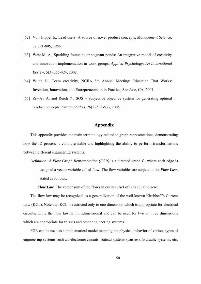
50
[62] Von Hippel E., Lead users: A source of novel product concepts, Management Science,
32:791-805, 1986.
[63] West M. A., Sparkling fountains or stagnant ponds: An integrative model of creativity
and innovation implementation in work groups, Applied Psychology: An International
Review, 5(3):355-424, 2002.
[64] Wilde D., Team creativity, NCIIA 8th Annual Meeting: Education That Works:
Invention, Innovation, and Entrepreneurship in Practice, San Jose, CA, 2004
[65] Ziv-Av A. and Reich Y., SOS – Subjective objective system for generating optimal
product concepts, Design Studies, 26(5):509-533, 2005.
Appendix
This appendix provides the main terminology related to graph representations, demonstrating
how the ID process is computerizable and highlighting the ability to perform transformations
between different engineering systems.
Definition: A Flow Graph Representation (FGR) is a directed graph G, where each edge is
assigned a vector variable called flow. The flow variables are subject to the Flow Law,
stated as follows:
Flow Law: The vector sum of the flows in every cutset of G is equal to zero.
The flow law may be recognized as a generalization of the well-known Kirchhoff’s Current
Law (KCL). Note that KCL is restricted only to one dimension which is appropriate for electrical
circuits, while the flow law is multidimensional and can be used for two or three dimensions
which are appropriate for trusses and other engineering systems.
FGR can be used as a mathematical model mapping the physical behavior of various types of
engineering systems such as: electronic circuits, statical systems (trusses), hydraulic systems, etc.

51
For example, Figure 15(a) shows a truss with two rods and one external force P. Its FGR, shown
in Figure 15(b), is constructed in a systematic way. A vertex is associated to each joint (vertex A
to joint A and vertex O to the two supports) and an edge to a rod (marked 2 and 3 on the graph,
corresponding to the rods). The unit vectors associated with the edges are also depicted in Figure
15(b). The unit vector xi)
corresponding to edge x is oriented in the same angle as rod x and is
drawn beside its corresponding edge.
The third edge in the graph denotes the external force P. In this graph, the spanning tree (a
tree containing all the vertices) is of size one, so edge 2 was chosen to be the spanning tree with a
single branch and is denoted by a dashed line.
Pi
2i
(a) (b) (c)
A
A
2
P 3i
2
3
P
3
( )1112P32
Q−++
=
O
Figure 15: A truss and its corresponding FGR. a) The truss. b) The corresponding FGR
in which edge 2 (the dashed line) was chosen to be the branch that defines the cutset. c)
The corresponding cutset matrix of the graph.
Usually, the data structure used to represent this graph is the cutset matrix Q (Balabanian and
Bickart, 1969). A cutset, defined by a branch, is a set of edges that partition the graph into two
parts, one containing the tail vertex of that branch and the other its head vertex. In the cutset
matrix Q, each row corresponds to a cutset defined by the corresponding branch. The matrix
entry ij is +1 if edge 'j' belongs to the cutset and with the same direction as the cutset (if its

52
tail/head vertex is in the same part of the graph as the tail/head vertex of branch 'i' defining the
cutset), otherwise it is –1. If edge 'j' is not included it the cutest, the entry is zero. The cutset
matrix of the graph in Figure 15(b) appears in Figure 15(c). The matrix consists of one row
related to branch 2 and the other two edges are included in that cutest. Thus, the entries
corresponding to these edges are +1 (or -1), since the edges are in the same (or opposite)
direction as the cutset, respectively.
With the cutest representation, the flow law can be written as:
0FQ = r⋅ , (1)
where Fr
is the vector of flows in the edges.
The second graph representation that we introduce in the appendix is the Potential Graph
Representation (PGR), shown in the map of representations (Figure 2) to be dual to the FGR.
Definition: Potential Graph Representation is a directed graph G, where each vertex is
assigned a vector variable called potential and each edge is assigned a vector variable
called potential difference. The potential difference of an edge is equal to the potential
of its head vertex minus the potential of its tail vertex. The potential variables are
subject to the Potential Law, stated as follows:
Potential Law: For every circuit in the graph, the vector sum of the potential differences of
the circuit edges of the circuit is equal to zero.
This law is a vectorial generalization to several dimensions of KVL (Kirchhoff’s Voltage Law)
which by itself is stated only for a one dimensional (scalar) system.
PGR can be used as a mathematical model mapping the physical behavior of various
engineering systems, for which the potential law is sufficient for their analysis, such as: the
kinematics of mechanisms, electronic circuits, and more.

53
Similar to FGR, PGR is constructed systematically. For a linkage, see Figure 16(a), the PGR
is constructed algorithmically by associating a vertex to each joint and an edge for a link. If two
vertices have the same potential at all times, they are contracted to one vertex, as shown in Figure
16(b). The information about the geometry is augmented to the graph by associating a unit vector
to each edge indicating the direction of the relative linear velocity of the corresponding link. In
the linkage appearing in Figure 16(a), a unit vector shown in Figure 16(b) is perpendicular to the
link and is designated by xπ for a link 'x'.
O1,2
B A
O2O1
AB
(a) (b)
1
2
3 11π
1
2π
2
3 3π ( )1112
321B
++−=
(c)
Figure 16: A linkage and its corresponding potential graph representation. a) The four-bar
linkage. b) The corresponding PGR in which {OA, OB} are the branched thus chord – AB
defines a circuit for which the corresponding equation can be generated. c) The corresponding
circuit matrix of the PGR.

54
Usually, the data structure used for this graph is the circuit matrix B (Balabanian and Bickart,
1969). The circuit matrix is constructed also by means of the spanning tree: the chords (any edge
that is not included in the spanning tree) define the circuits, so that each circuit includes a single
chord and a number of branches of the spanning tree. For example, the PGR (Figure 16(b)) of the
linkage (Figure 16(a)) contains only one chord thus the circuit matrix contains only one row
(Figure 16(c)). As the process of constructing the circuit matrix is similar to that of the cutset
matrix explained above, it will not be introduced here in details. Moreover, due to a mathematical
correlation there is a well known procedure enabling to deduce the circuit matrix from the cutset
matrix for a given graph by using the following equation (Balabanian and Bickart, 1969):
)|( IQB tc−= , (2)
where cQ is the sub-matrix of the cutset matrix containing all the rows and those columns
corresponding to the chords, and I is the unit matrix.
In the circuit matrix B, each row corresponds to a chord and the columns to the edges, thus
the potential law can be reformulated as follows:
0Brr
=⋅ Δ (3)
where Δr
is the vector of potential differences.
The process of constructing the dual system through the graph representations
It has been mathematically proven (Shai 2002) that PGR and FGR are graph representations
that are dual to one another. Section 3.1 indicated that when two graph representations are dual, it
is possible to construct, in a systematic way, the dual engineering system that usually belongs to
another engineering domain. Below we explain, through an example, the process of constructing
the dual truss for a given linkage.

55
Step 1: Construct the graph representation of the given engineering system, in this case the
PGR of the linkage. The PGR contains both the topological information in the form of
the graph structure and the geometry information of the linkage in the form of the unit
vectors perpendicular to the links and associated with the graph edges.
Step 2: Construct the dual graph by applying the following algorithm:
a. For each face (a closed circuit without inner edges), associate a vertex in the dual graph.
b. For each two adjacent faces, associate an edge between the two corresponding vertices in
the dual graph.
Step 3: Transfer the geometry information from the PGR to the dual graph FGR by associating
the unit vectors to each corresponding edge in the dual graph. The physical
interpretation of the unit vectors is transferred from indication on the perpendicular
direction to the link to the indication on the orientation of the corresponding dual rod in
the truss. This step is performed by applying the following equality for all the edges of
the graph: xπ = xi
Step 4: The dual graph is proved to be FGR and since it possesses both the topology and the
geometry, one may use it to construct the dual engineering system – the dual truss.
Figure 17 demonstrates the above process and shows how the linkage of Figure 16(a) (also
Figure 17(a)) is transformed into its dual truss of Figure 15(a) (also Figure 17(f)).

56
O1,2
B A
O2O1
AB
1
2
3
11π
1
2π
2
3
3π
O1,2
AB
1
2
3
3
2
3
2
3i
2iPi P 2
3
(a) (b) (c)
(d) (e) (f)
11π
2π
3π
Figure 17: The process of constructing the dual truss from a given linkage.
a kinematical linkage, (b) A graph representation of the linkage without unit vectors (the
topology of the PGR). (c) The topology part of the PGR and its dual graph superimposed. (d) The
unit vectors of the PGR are associated to the corresponding edges in the dual graph. (e) Changing
the physical interpretation of the unit vectors thus now the dual graph becomes FGR. (f) The dual
truss corresponding to the FGR appearing in (e).