CREATION OF A VIRTUAL OVERLAY NETWORK WITH SDN AND … · overlay network on existing Layer 3...
115
CREATION OF A VIRTUAL OVERLAY NETWORK WITH SDN AND VXLAN A Degree Thesis Submitted to the Faculty of the Escola Tècnica d'Enginyeria de Telecomunicació de Barcelona Universitat Politècnica de Catalunya by Fernando Lama Ruano In partial fulfilment of the requirements for the degree in Telematics ENGINEERING Advisor: Jose Luis Muñoz Tapia Barcelona, June 2017
Transcript of CREATION OF A VIRTUAL OVERLAY NETWORK WITH SDN AND … · overlay network on existing Layer 3...
CREATION OF A VIRTUAL OVERLAY NETWORK WITHSDN AND VXLAN
A Degree Thesis
Submitted to the Faculty of the
Escola Tècnica d'Enginyeria de Telecomunicació deBarcelona
Universitat Politècnica de Catalunya
by
Fernando Lama Ruano
In partial fulfilment
of the requirements for the degree in
Telematics ENGINEERING
Advisor: Jose Luis Muñoz Tapia
Barcelona, June 2017
Abstract
The developed project has consisted in the creation of a virtual overlay VXLAN (Virtual Extensible LAN) between several nodes using SDN (Software Defined Networks) and more specifically the RYU framework. The idea of VXLAN is to connect two physically separated networks using the same IP block.
The switches used are OVS (Open vSwitch), in them you can manually implement the VXLAN tunnel and you can also implement the SDN technology in them. But in this project we will use the framework Ryu, it is fully developed in python and with it we will create a controller that will manage and manage all the ovs of the network creating the overlay and managing the flows of each port of each switch.
1
Resum
El projecte desenvolupat ha consistit en la creació d'una superposició virtual VXLAN (Virtual Extensible LAN) entre diversos nodes utilitzant SDN (Software Defined Networks)i més concretament el framework RYU. La idea d'VXLAN és connectar dues xarxes separades físicament utilitzant el mateix bloc IP.
Els switchs utilitzats són OVS (Open vSwitch), en ells es pot implementar manualment el tunnel VXLAN i també es pot implementar la tecnologia SDN en ells. Però en aquest projecte utilitzarem el framework Ryu, aquesta desenvolupat íntegrament en python i amb el crearem un controlador que administrarà i gestionarà tots els OVS de la xarxa creant la superposició i gestionant els fluxos de cada port de cada switch.
2
Resumen
El proyecto desarrollado ha consistido en la creación de una overlay virtual VXLAN( Virtual Extensible LAN) entre varios nodos utilizando SDN (Software Defined Networks)y más concretamente el framework RYU. La idea de VXLAN es conectar dos redesseparadas físicamente utilizando el mismo bloque IP.
Los switchs utilizados son OVS ( Open vSwitch ), en ellos se puede implementarmanualmente el tunnel VXLAN y también se puede implementar la tecnologia SDN enellos. Pero en este proyecto utilizaremos el framework Ryu, esta desarrolladointegramente en python y con el crearemos un controlador que administrará y gestionarátodos los ovs de la red creando la overlay y gestionando los flujos de cada puerto decada switch.
3
Acknowledgements
I would like to express my gratitude to this project advisor, Jose Luis Muñoz Tapia, for
having proposed this thesis' topic, as well as for keeping a periodical tracking of the
thesis and suggesting ideas to improve it.
4
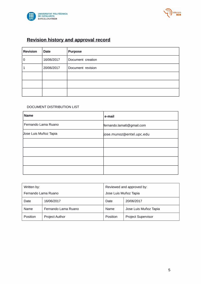
Revision history and approval record
Revision Date Purpose
0 16/06/2017 Document creation
1 20/06/2017 Document revision
DOCUMENT DISTRIBUTION LIST
Name e-mail
Fernando Lama Ruano [email protected]
Jose Luis Muñoz Tapia [email protected]
Written by:
Fernando Lama Ruano
Reviewed and approved by:
Jose Luis Muñoz Tapia
Date 16/06/2017 Date 20/06/2017
Name Fernando Lama Ruano Name Jose Luis Muñoz Tapia
Position Project Author Position Project Supervisor
5
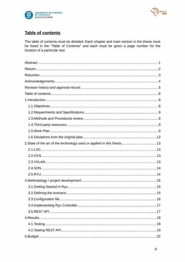
Table of contents
The table of contents must be detailed. Each chapter and main section in the thesis mustbe listed in the “Table of Contents” and each must be given a page number for thelocation of a particular text.
Abstract.............................................................................................................................1
Resum...............................................................................................................................2
Resumen...........................................................................................................................3
Acknowledgements............................................................................................................4
Revision history and approval record.................................................................................5
Table of contents................................................................................................................6
1.Introduction.....................................................................................................................8
1.1.Objectives................................................................................................................8
1.2.Requeriments and Specifications.............................................................................9
1.3.Methods and Procedures review..............................................................................9
1.4.Third-party resources...............................................................................................9
1.5.Work Plan.................................................................................................................9
1.6.Deviations from the original plan............................................................................12
2.State of the art of the technology used or applied in this thesis:...................................13
2.1.LXC........................................................................................................................13
2.2.OVS.......................................................................................................................13
2.3.VXLAN...................................................................................................................13
2.4.SDN.......................................................................................................................14
2.5.RYU.......................................................................................................................14
3.Methodology / project development:.............................................................................15
3.1.Getting Started in Ryu............................................................................................15
3.2.Defining the scenario..............................................................................................15
3.3.Configuration file....................................................................................................16
3.4.Implementing Ryu Controller..................................................................................17
3.5.REST API...............................................................................................................17
4.Results..........................................................................................................................18
4.1.Testing....................................................................................................................18
4.2.Testing REST API...................................................................................................19
5.Budget..........................................................................................................................22
6

6.Conclusions and future development:...........................................................................23
Bibliography:....................................................................................................................24
Glossary..........................................................................................................................25
Appendices:.....................................................................................................................26
7
1. Introduction
An Introduction that clearly states the rationale of the thesis that includes:
a. Statement of purpose (objectives).
b. Requirements and specifications.
c. Methods and procedures, citing if this work is a continuation of another project orit uses applications, algorithms, software or hardware previously developed byother authors.
d. Work plan with tasks, milestones and a Gantt diagram.
e. Description of the deviations from the initial plan and incidences that may haveoccurred.
The minimum chapters that this thesis document should have are described below,nevertheless they can have different names and more chapters can be added.
In the introductory section an overview of the project is explained, including: Objectives,requirements and specifications, methods and procedures, work plan, deviations from the
initial plan and incidences.
1.1. Objectives
The purpose of this project has been to learn how to use the Ryu framework in order tocreate and manage the VXLAN overlay in a specific scenario.
The basic objectives have been to understand how all the technologies involved work:VXLAN, SDN, LXC, OVS, RYU. In order to know the possibilities and potential of eachone of them.
The main objectives have been:
- Create a VXLAN tunnel between two OVS with RYU.
- Manage the flows of each port with a RYU controller.
- Make the two previous goals scalable to create the overlay between more nodes.
- Add REST API functionality to the controller.
8
1.2. Requeriments and Specifications
The requirements of this project can be separated into two groups:
Theoretical requirements:o Knowledge of VXLAN overlay.o Knowledge of SDN.o Knowledge of Ryu APi and python.
Practical requirements:o Use of Linux.o LXC virtual containers (virtual machines in the scenarios).o Use of OVS (Open vSwitch)
1.3. Methods and Procedures review
The following procedures have been done during the project:
Studying how works VXLAN. Studying how works SDN in OVS. Studying Ryu API. Develop litlle scenarios fort testing Vxlan between ovs. Developing litlle scenarios fort testing little Ryu apps. Create the first ryu app to set the Vxlan tunnel. Create a Ryu app that controls the incoming and outgoing packets of each port,
and install the necessary flows. Join all of the above in a single Ryu app. Implementing REST APIs in our system.
1.4. Third-party resources
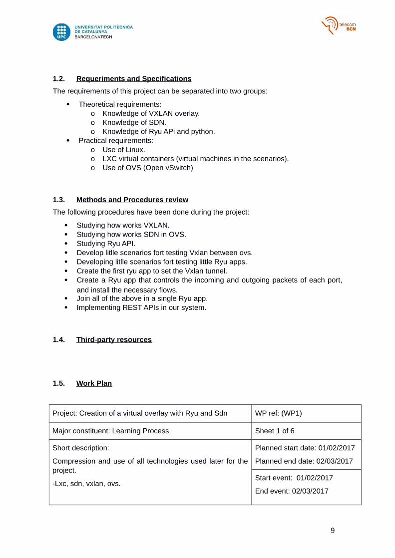
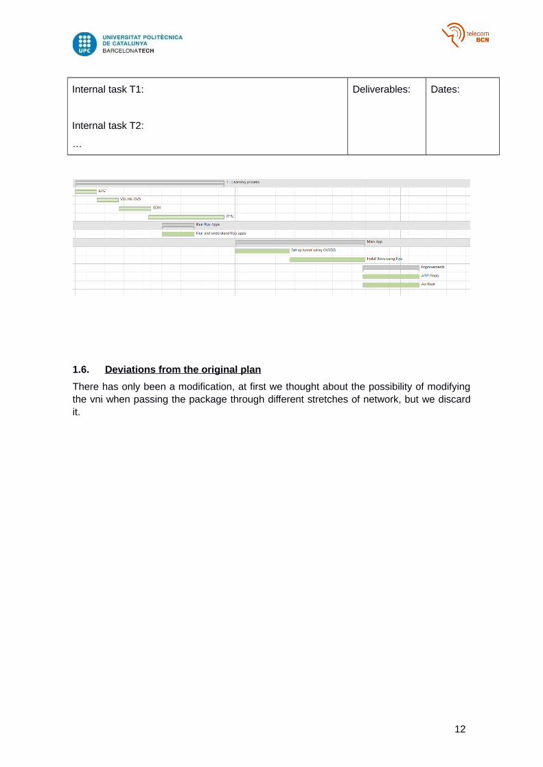
1.5. Work Plan
Project: Creation of a virtual overlay with Ryu and Sdn WP ref: (WP1)
Major constituent: Learning Process Sheet 1 of 6
Short description:
Compression and use of all technologies used later for theproject.
-Lxc, sdn, vxlan, ovs.
Planned start date: 01/02/2017
Planned end date: 02/03/2017
Start event: 01/02/2017
End event: 02/03/2017
9
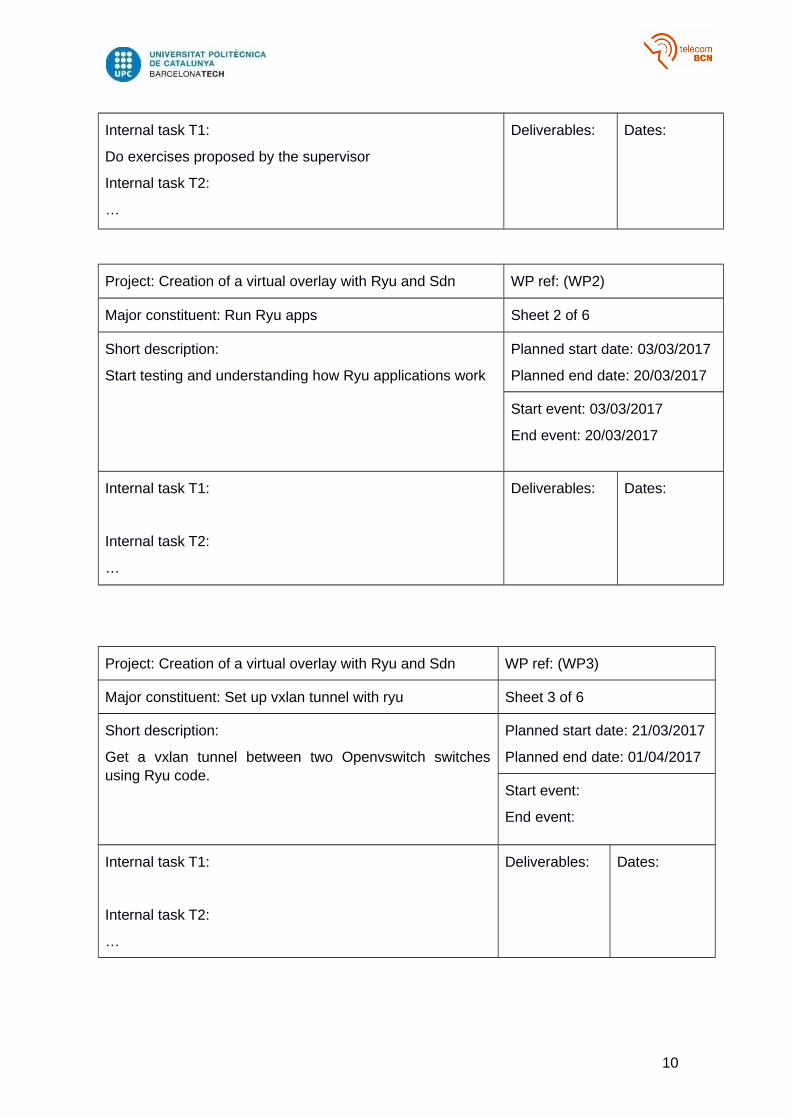
Internal task T1:
Do exercises proposed by the supervisor
Internal task T2:
…
Deliverables: Dates:
Project: Creation of a virtual overlay with Ryu and Sdn WP ref: (WP2)
Major constituent: Run Ryu apps Sheet 2 of 6
Short description:
Start testing and understanding how Ryu applications work
Planned start date: 03/03/2017
Planned end date: 20/03/2017
Start event: 03/03/2017
End event: 20/03/2017
Internal task T1:
Internal task T2:
…
Deliverables: Dates:
Project: Creation of a virtual overlay with Ryu and Sdn WP ref: (WP3)
Major constituent: Set up vxlan tunnel with ryu Sheet 3 of 6
Short description:
Get a vxlan tunnel between two Openvswitch switchesusing Ryu code.
Planned start date: 21/03/2017
Planned end date: 01/04/2017
Start event:
End event:
Internal task T1:
Internal task T2:
…
Deliverables: Dates:
10
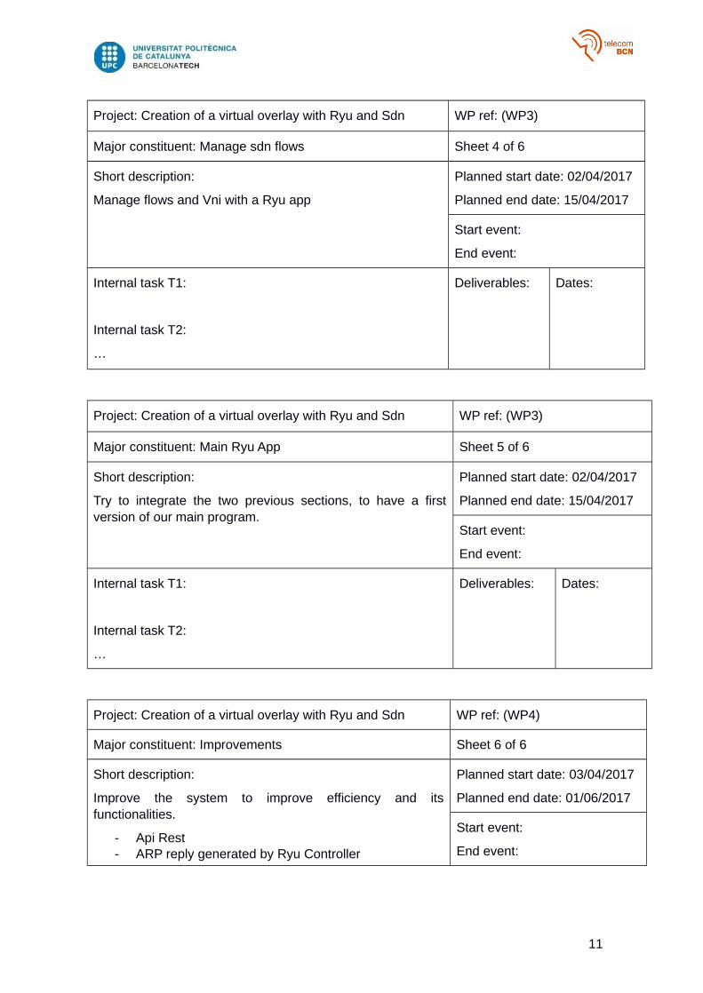
Project: Creation of a virtual overlay with Ryu and Sdn WP ref: (WP3)
Major constituent: Manage sdn flows Sheet 4 of 6
Short description:
Manage flows and Vni with a Ryu app
Planned start date: 02/04/2017
Planned end date: 15/04/2017
Start event:
End event:
Internal task T1:
Internal task T2:
…
Deliverables: Dates:
Project: Creation of a virtual overlay with Ryu and Sdn WP ref: (WP3)
Major constituent: Main Ryu App Sheet 5 of 6
Short description:
Try to integrate the two previous sections, to have a firstversion of our main program.
Planned start date: 02/04/2017
Planned end date: 15/04/2017
Start event:
End event:
Internal task T1:
Internal task T2:
…
Deliverables: Dates:
Project: Creation of a virtual overlay with Ryu and Sdn WP ref: (WP4)
Major constituent: Improvements Sheet 6 of 6
Short description:
Improve the system to improve efficiency and itsfunctionalities.
- Api Rest- ARP reply generated by Ryu Controller
Planned start date: 03/04/2017
Planned end date: 01/06/2017
Start event:
End event:
11
Internal task T1:
Internal task T2:
…
Deliverables: Dates:
1.6. Deviations from the original plan
There has only been a modification, at first we thought about the possibility of modifyingthe vni when passing the package through different stretches of network, but we discardit.
12
2. State of the art of the technology used or applied in this
thesis:
The technologies used in this project are VXLAN, SDN, LXC, RYU and OVS.
2.1. LXC
Linux Containers (LXC) is an operating-system-level virtualization method for runningmultiple isolated Linux systems (containers) on a single control host (LXC host). It doesnot provide a virtual machine, but rather provides a virtual environment that has its ownCPU, memory, block I/O, network, etc. space and the resource control mechanism. Thisis provided by namespaces and cgroups features in Linux kernel on LXC host. It is similarto a chroot, but offers much more isolation.
2.2. OVS
Open vSwitch is an open-source project that allows hypervisors to virtualize thenetworking layer. This caters for the large number of virtual machines running on one ormore physical nodes. The virtual machines connect to virtual ports on virtual bridges(inside the virtualized network layer.)
This is very similar to a physical server connecting to physical ports on a Layer 2networking switch. These virtual bridges then allow the virtual machines to communicatewith each other on the same physical node. These bridges also connect these virtualmachines to the physical network for communication outside the hypervisor node.
2.3. VXLAN
Virtual Extensible LAN (VXLAN) is a proposed encapsulation protocol for running anoverlay network on existing Layer 3 infrastructure. An overlay network is a virtual networkthat is built on top of existing network Layer 2 and Layer 3 technologies to support elasticcompute architectures. VXLAN will make it easier for network engineers to scale out acloud computing environment while logically isolating cloud apps and tenants.
A cloud computing architecture is by definition, multi-tenant; each tenant requires its ownlogical network, which in turn, requires its own network identification (network ID).Traditionally, network engineers have used virtual LANs (VLANs) to isolate apps andtenants in a cloud computing environment but VLAN specifications only allow for up to4,096 network IDs to be assigned at any given time -- which may not be enoughaddresses for a large cloud computing environment.
The primary goal of VXLAN is to extend the virtual LAN (VLAN) address space by addinga 24-bit segment ID and increasing the number of available IDs to 16 million. The VXLANsegment ID in each frame differentiates individual logical networks so millions of isolatedLayer 2 VXLAN networks can co-exist on a common Layer 3 infrastructure. As withVLANs, only virtual machines (VMs) within the same logical network can communicatewith each other.
13
If approved, VXLAN can potentially allow network engineers to migrate virtual machinesacross long distances and play an important role in a software-defined networking (SDN),an emerging architecture that allows a server or controller to tell network switches whereto send packets. In a conventional network, each switch has proprietary software thattells it what to do. In a software-defined network, packet-moving decisions are centralizedand network traffic flow can be programmed independently of individual switches anddata center gear. To implement SDN using VXLAN, administrators can use existinghardware and software, a feature that makes the technology financially attractive.
2.4. SDN
Software-Defined Networking (SDN) is a network architecture approach that enables thenetwork to be intelligently and centrally controlled, or ‘programmed,’ using softwareapplications. This helps operators manage the entire network consistently and holistically,regardless of the underlying network technology.
Enterprises, carriers, and service providers are being surrounded by a number ofcompeting forces. The monumental growth in multimedia content, the explosion of cloudcomputing, the impact of increasing mobile usage, and continuing business pressures toreduce costs while revenues remain flat are all converging to wreak havoc on traditionalbusiness models.
To keep pace, many of these players are turning to SDN technology to revolutionizenetwork design and operations.
SDN enables the programming of network behavior in a centrally controlled mannerthrough software applications using open APIs. By opening up traditionally closednetwork platforms and implementing a common SDN control layer, operators can managethe entire network and its devices consistently, regardless of the complexity of theunderlying network technology.
2.5. RYU
Ryu is a component-based software defined networking framework.
Ryu provides software components with well-defined API that make it easy for developersto create new network management and control applications. Ryu supports variousprotocols for managing network devices, such as OpenFlow,
Netconf, OF-config, etc. About OpenFlow, Ryu supports fully 1.0, 1.2, 1.3, 1.4, 1.5 andNicira Extensions.
All of the code is freely available under the Apache 2.0 license. Ryu is fully written inPython.
Ryu Official site is http://osrg.github.io/ryu/.
14
3. Methodology / project development:
The methodology followed to develop this project was based first on studying and doingpractices with the technologies used. These exercises and practices have been providedto me by the supervisor.
The exercises consisted of creating scenarios with lxc and Open vSwitch and establishing vxlan tunnels manually.
Also exercises with ovs and openflow, introducing flows directly in the switches.
And finally these two types of exercises together.
3.1. Getting Started in Ryu
Then to begin to understand Ryu and its operation, start with an easy example, the simple switch.
https://osrg.github.io/ryu-book/en/html/switching_hub.html
This is a very good example for our final objective, because it creates all the functionalities of a simple switch, the mac learning, how flows are added, how to send thepackages by the corresponding port and the handling of events.
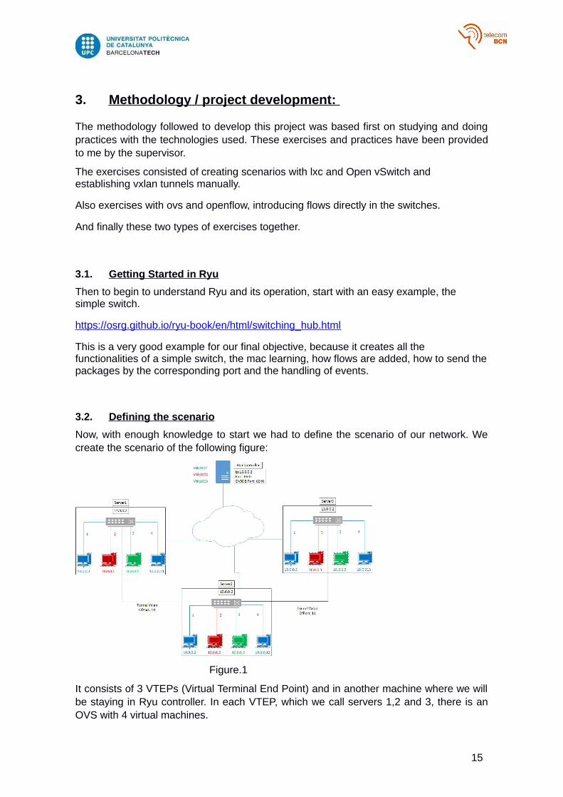
3.2. Defining the scenario
Now, with enough knowledge to start we had to define the scenario of our network. Wecreate the scenario of the following figure:
Figure.1
It consists of 3 VTEPs (Virtual Terminal End Point) and in another machine where we willbe staying in Ryu controller. In each VTEP, which we call servers 1,2 and 3, there is anOVS with 4 virtual machines.
15
We will also define 3 VNI (VXLAN Network Identifier) and each port will have a VNIassigned.
The OVS must be assigned the Ryu controller in the IP and port indicated in the figure.And once this scenario is established, we can begin to create our program.
3.3. Configuration file
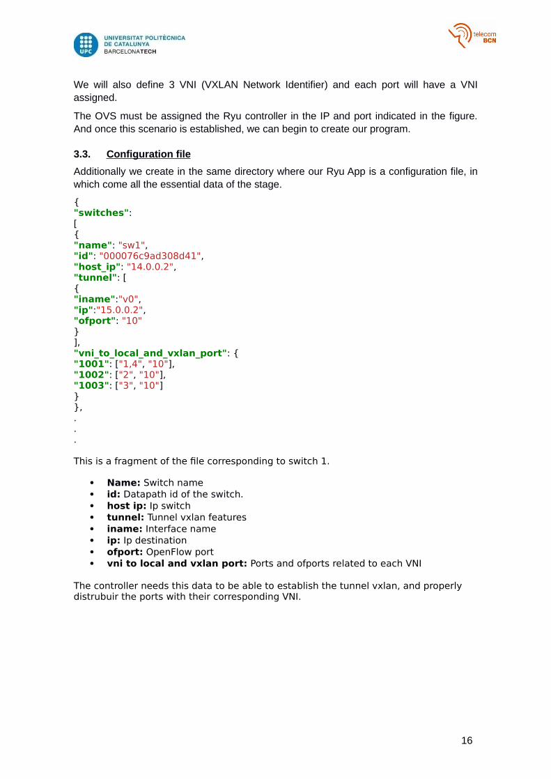
Additionally we create in the same directory where our Ryu App is a configuration file, inwhich come all the essential data of the stage.
{"switches":[{"name": "sw1","id": "000076c9ad308d41","host_ip": "14.0.0.2","tunnel": [{"iname":"v0","ip":"15.0.0.2","ofport": "10"}],"vni_to_local_and_vxlan_port": {"1001": ["1,4", "10"],"1002": ["2", "10"],"1003": ["3", "10"]}},...
This is a fragment of the file corresponding to switch 1.
Name: Switch name id: Datapath id of the switch. host ip: Ip switch tunnel: Tunnel vxlan features iname: Interface name ip: Ip destination ofport: OpenFlow port vni to local and vxlan port: Ports and ofports related to each VNI
The controller needs this data to be able to establish the tunnel vxlan, and properly distrubuir the ports with their corresponding VNI.
16
3.4. Implementing Ryu Controller
In the appendices you will see in detail all the code explained and its functions. In short, itconsists of 3 different parts:
Read the configuration file Automatically generate the tunnels shown in the previous figure. Control each packet that enters or exits one of the 3 switches, adding the
necessary flows, differentiating between unicast and broadcast traffic.
3.5. REST API
As an improvement, we decided to implement REST API functionality. REST API is anapplication program interface (API) that uses HTTP requests to GET, PUT, POST andDELETE data.
With this, the user can know the status of the switches, ports, flows, vni of our network.And you can also modify or delete them.
17
4. Results
In this section briefly describe the results obtained, in the appendices you can see in full all the tests performed in more detail.
4.1. Testing
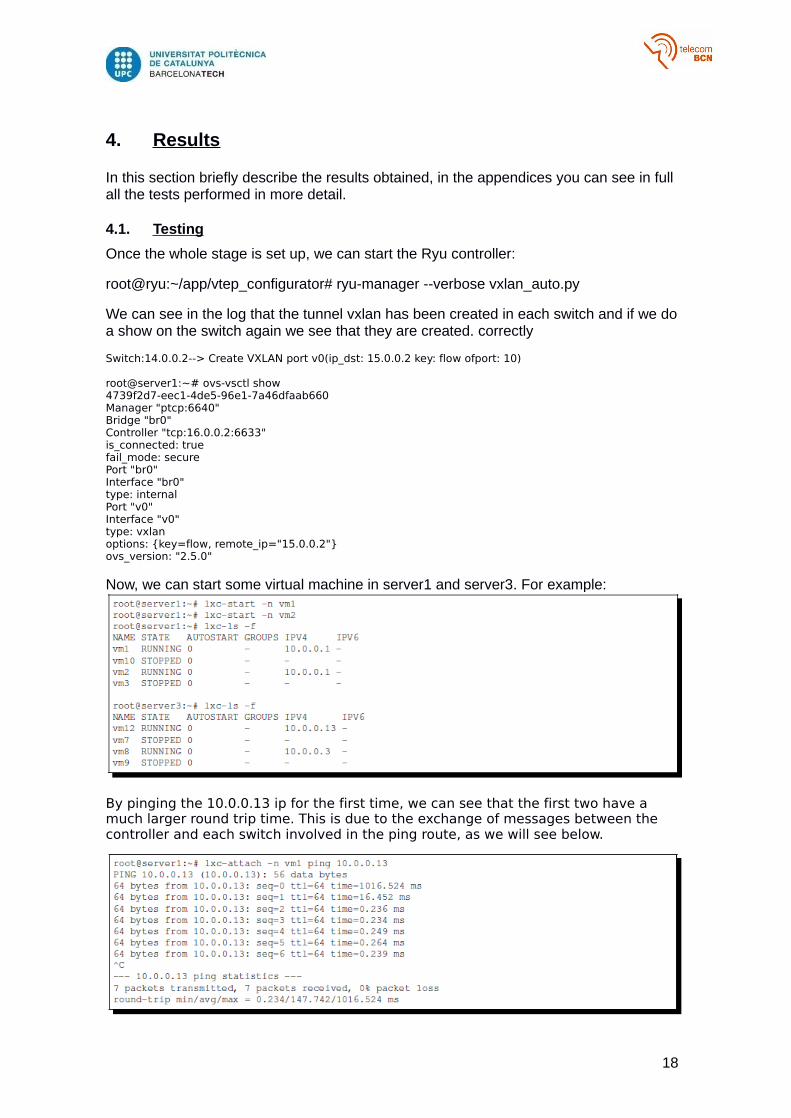
Once the whole stage is set up, we can start the Ryu controller:
root@ryu:~/app/vtep_configurator# ryu-manager --verbose vxlan_auto.py
We can see in the log that the tunnel vxlan has been created in each switch and if we do a show on the switch again we see that they are created. correctly
Switch:14.0.0.2--> Create VXLAN port v0(ip_dst: 15.0.0.2 key: flow ofport: 10)
root@server1:~# ovs-vsctl show4739f2d7-eec1-4de5-96e1-7a46dfaab660Manager "ptcp:6640"Bridge "br0"Controller "tcp:16.0.0.2:6633"is_connected: truefail_mode: securePort "br0"Interface "br0"type: internalPort "v0"Interface "v0"type: vxlanoptions: {key=flow, remote_ip="15.0.0.2"}ovs_version: "2.5.0"
Now, we can start some virtual machine in server1 and server3. For example:
By pinging the 10.0.0.13 ip for the first time, we can see that the first two have a much larger round trip time. This is due to the exchange of messages between the controller and each switch involved in the ping route, as we will see below.
18
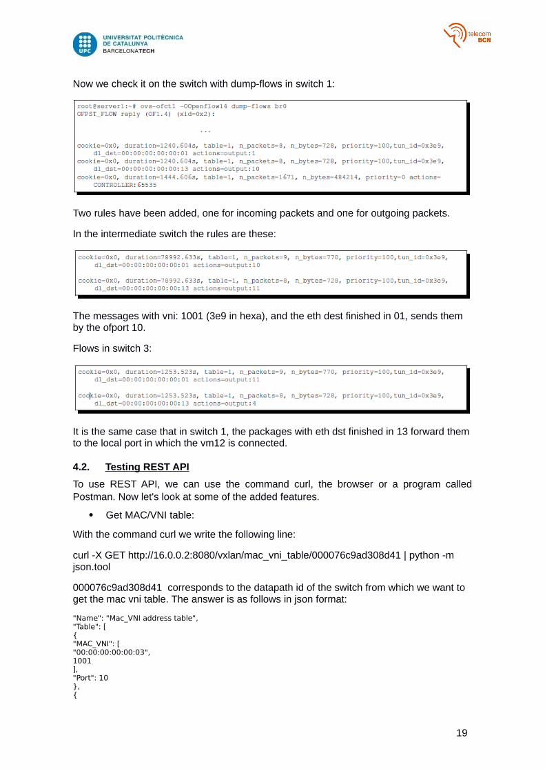
Now we check it on the switch with dump-flows in switch 1:
Two rules have been added, one for incoming packets and one for outgoing packets.
In the intermediate switch the rules are these:
The messages with vni: 1001 (3e9 in hexa), and the eth dest finished in 01, sends them by the ofport 10.
Flows in switch 3:
It is the same case that in switch 1, the packages with eth dst finished in 13 forward them to the local port in which the vm12 is connected.
4.2. Testing REST API
To use REST API, we can use the command curl, the browser or a program calledPostman. Now let's look at some of the added features.
Get MAC/VNI table:
With the command curl we write the following line:
curl -X GET http://16.0.0.2:8080/vxlan/mac_vni_table/000076c9ad308d41 | python -m json.tool
000076c9ad308d41 corresponds to the datapath id of the switch from which we want to get the mac vni table. The answer is as follows in json format:
"Name": "Mac_VNI address table","Table": [{"MAC_VNI": ["00:00:00:00:00:03",1001],"Port": 10},{
19
"MAC_VNI": ["00:00:00:00:00:10",1001],"Port": 4},{"MAC_VNI": ["00:00:00:00:00:03",1003],"Port": 10},{"MAC_VNI": ["00:00:00:00:00:66","1002"],"Port": 10},{"MAC_VNI": ["00:00:00:00:00:01",1003],"Port": 3}]
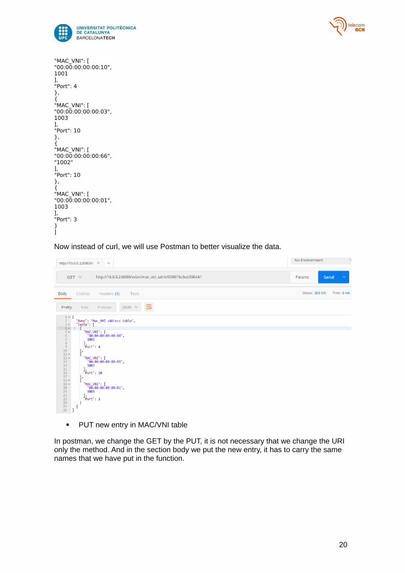
Now instead of curl, we will use Postman to better visualize the data.
PUT new entry in MAC/VNI table
In postman, we change the GET by the PUT, it is not necessary that we change the URI only the method. And in the section body we put the new entry, it has to carry the same names that we have put in the function.
20
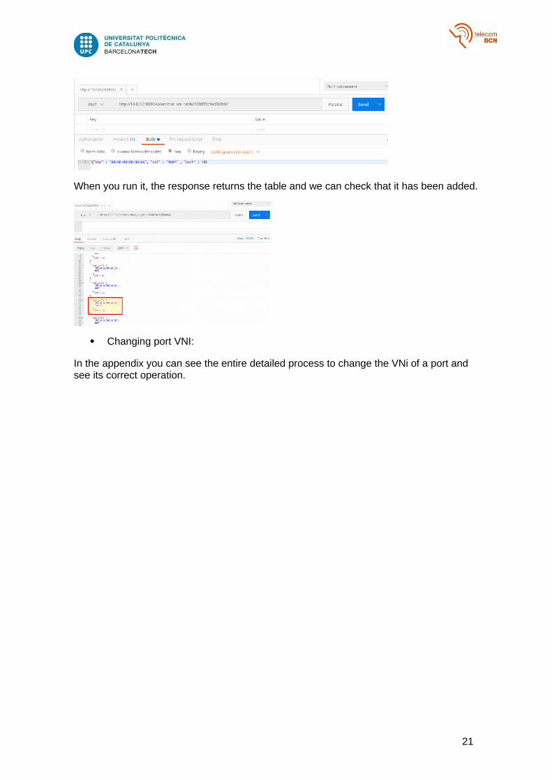
When you run it, the response returns the table and we can check that it has been added.
Changing port VNI:
In the appendix you can see the entire detailed process to change the VNi of a port and see its correct operation.
21

5. Budget
The approximate amount of hours dedicated to the project is 524h. Taking into accountthat the approximate salary of a junior engineer is about 11,5€/h, this would supposeabout 6026€All the software used in the project is open-source and free. This means that there are noadded costs.The final cost of the project would be 6026€.
22
6. Conclusions and future development:
In this chapter, the conclusions will be collected after the completion of the present Workof Degree in everything related to it as well as a series of possible future routes.
Therefore, we will present some relevant issues arising from the elaboration as well asthe contributions made to the field in which we have worked. The possibilities that arepresented for the development of new future lines from the work carried out in this projectwill also be discussed.
In this final project of degree has been designed a virtual scenario with an SDN networkand a VXLAN overlay, all this network managed and controlled by a RYU controller, whichwe have also programmed.
The environment you create is similar to a virtualized cloud environment. The use ofVXLAN increases scalability, Vxlan ID is 24 bits, which allows you to create 16 milliondifferent isolated networks.
Eliminates the need for additional physical infrastructure.
Reduce the scope of MAC address replication to VMs that exist on the sameVXLAN segment.
Allows you to use the layer 3 functions of the underlying network.
Ryu is an SDN framework that allows you to create network management and controlapplications. With the emergence of SDN and Ryu eliminates the slow in innovation ownof the hardware, allows the use of more complex algorithms, optimizes the cost ofnetworking hardware.
With Ryu we can make the network behave the way we want, and with all theparticularities possible. Being controlled by software does not add any extra cost, it onlyvaries in complexity the code.
We have also introduced the use of the REST API to the Ryu controller. This allows theuser or administrator of this network to make changes to it without having to modify thecode. As we have seen previously, simply with a GET or PUT is simple to introduce thistype of changes. The downside of this REST API is that it is not able to react to events, itwould be interesting that it could react to them as it would open up a lot of possibilitiesand functionalities.
23
Bibliography:
[1] RYU SDN Framework - English Edition Release 1.0,
https://osrg.github.io/ryu-book/en/Ryubook.pdf
[2] Ryu component-based software defined networking framework ,
https://osrg.github.io/ryu/
[3] Aki Tuomi, Python-ryu application for automated vxlan tunnels ,
https://github.com/cmouse/ryu-auto-vxlan
[4] ryu.app.ofctl_rest,
http://ryu.readthedocs.io/en/latest/app/ofctl_rest.html
24
Glossary
LXC Linux Containers
OVS Open vSwitch
VXLAN Virtual eXtensible LAN
SDN Software Defined Networks
VNI VXLAN Network Identifier
25

Appendices:
26

27
Fernando Lama & Jose L. Muñoz
UPC Telematics Department
Creation of a virtual overlay network with SDN andVXLAN

Contents
I Creation of a virtual overlay network with Ryu and VXLAN 7
1 Introduction 9
1.1 Purpose of the project . . . . . . . . . . . . . . . . . . . . . . . . . . . . . . . . . . . . . . . . . . . 9
1.2 Motivation . . . . . . . . . . . . . . . . . . . . . . . . . . . . . . . . . . . . . . . . . . . . . . . . . 10
1.3 Openflow . . . . . . . . . . . . . . . . . . . . . . . . . . . . . . . . . . . . . . . . . . . . . . . . . 11
1.4 What is RYU Controller? . . . . . . . . . . . . . . . . . . . . . . . . . . . . . . . . . . . . . . . . . 12
1.5 VXLAN . . . . . . . . . . . . . . . . . . . . . . . . . . . . . . . . . . . . . . . . . . . . . . . . . . 13
1.5.1 Introduction . . . . . . . . . . . . . . . . . . . . . . . . . . . . . . . . . . . . . . . . . . . . 13
1.5.2 Tunneling . . . . . . . . . . . . . . . . . . . . . . . . . . . . . . . . . . . . . . . . . . . . . 13
1.5.3 VXLAN Headers . . . . . . . . . . . . . . . . . . . . . . . . . . . . . . . . . . . . . . . . . 14
1.5.4 Entropy . . . . . . . . . . . . . . . . . . . . . . . . . . . . . . . . . . . . . . . . . . . . . . 15
1.5.5 Learning-based Control Plane . . . . . . . . . . . . . . . . . . . . . . . . . . . . . . . . . . 16
1.5.6 Other Control Planes . . . . . . . . . . . . . . . . . . . . . . . . . . . . . . . . . . . . . . . 17
1.5.7 Linux Kernel Implementation . . . . . . . . . . . . . . . . . . . . . . . . . . . . . . . . . . 18
1.5.8 OVS Implementation . . . . . . . . . . . . . . . . . . . . . . . . . . . . . . . . . . . . . . . 21
2 Network and Topology set up 25
2.1 Description . . . . . . . . . . . . . . . . . . . . . . . . . . . . . . . . . . . . . . . . . . . . . . . . 25
2.2 Overview . . . . . . . . . . . . . . . . . . . . . . . . . . . . . . . . . . . . . . . . . . . . . . . . . 26
2.2.1 Scenario . . . . . . . . . . . . . . . . . . . . . . . . . . . . . . . . . . . . . . . . . . . . . . 26
2.2.2 RYU controller . . . . . . . . . . . . . . . . . . . . . . . . . . . . . . . . . . . . . . . . . . 27
2.2.3 Configuration file . . . . . . . . . . . . . . . . . . . . . . . . . . . . . . . . . . . . . . . . 28
2.3 LXC . . . . . . . . . . . . . . . . . . . . . . . . . . . . . . . . . . . . . . . . . . . . . . . . . . . . 30
2.4 Steps . . . . . . . . . . . . . . . . . . . . . . . . . . . . . . . . . . . . . . . . . . . . . . . . . . . . 31
2.4.1 Creating scenario . . . . . . . . . . . . . . . . . . . . . . . . . . . . . . . . . . . . . . . . . 31
3 Ryu Controller 35
3.1 Objective . . . . . . . . . . . . . . . . . . . . . . . . . . . . . . . . . . . . . . . . . . . . . . . . . 35
3.2 Usefull messages . . . . . . . . . . . . . . . . . . . . . . . . . . . . . . . . . . . . . . . . . . . . . 35
3.3 Ryu application programming model . . . . . . . . . . . . . . . . . . . . . . . . . . . . . . . . . . 37
3.3.1 Creating switch class . . . . . . . . . . . . . . . . . . . . . . . . . . . . . . . . . . . . . . . 37
3.3.2 Read configuration file . . . . . . . . . . . . . . . . . . . . . . . . . . . . . . . . . . . . . . 37
3.3.3 Events . . . . . . . . . . . . . . . . . . . . . . . . . . . . . . . . . . . . . . . . . . . . . . 38
3.3.4 Set up Vxlan tunnel . . . . . . . . . . . . . . . . . . . . . . . . . . . . . . . . . . . . . . . . 39
3.3.5 Connection up handler . . . . . . . . . . . . . . . . . . . . . . . . . . . . . . . . . . . . . . 41
3.3.6 Packet in handler . . . . . . . . . . . . . . . . . . . . . . . . . . . . . . . . . . . . . . . . . 42
4 Test 47
4.1 Introduction . . . . . . . . . . . . . . . . . . . . . . . . . . . . . . . . . . . . . . . . . . . . . . . . 47
4.2 Firsts steps . . . . . . . . . . . . . . . . . . . . . . . . . . . . . . . . . . . . . . . . . . . . . . . . 47
4.2.1 Run ryu app . . . . . . . . . . . . . . . . . . . . . . . . . . . . . . . . . . . . . . . . . . . . 48
4.2.2 Starting virtual machines . . . . . . . . . . . . . . . . . . . . . . . . . . . . . . . . . . . . . 49
5 REST API 55
5.1 Introduction . . . . . . . . . . . . . . . . . . . . . . . . . . . . . . . . . . . . . . . . . . . . . . . . 55
5.2 Built-in Ryu applications (ryu.app.ofctl_rest) . . . . . . . . . . . . . . . . . . . . . . . . . . . . . . 55
5.3 Integrating Rest Api . . . . . . . . . . . . . . . . . . . . . . . . . . . . . . . . . . . . . . . . . . . . 56
5.4 Implementing our REST API . . . . . . . . . . . . . . . . . . . . . . . . . . . . . . . . . . . . . . . 57
5.4.1 VxlanRestController Class . . . . . . . . . . . . . . . . . . . . . . . . . . . . . . . . . . . 58
5.4.2 Update MAC VNI table . . . . . . . . . . . . . . . . . . . . . . . . . . . . . . . . . . . . . 59
5.4.3 Get and Modify port VNI . . . . . . . . . . . . . . . . . . . . . . . . . . . . . . . . . . . . 60
5.4.4 Executing Rest API added Vtep Controller . . . . . . . . . . . . . . . . . . . . . . . . . . . 63
A Appendix 71
A.1 Source code vxlan_auto.py . . . . . . . . . . . . . . . . . . . . . . . . . . . . . . . . . . . . . . . . 71
A.2 CONFIG.json . . . . . . . . . . . . . . . . . . . . . . . . . . . . . . . . . . . . . . . . . . . . . . . 84
5

6
Part I
Creation of a virtual overlay network withRyu and VXLAN
7

Chapter 1
Introduction
1.1 Purpose of the project
The purpose of the project is to create a tunnel VXLAN between two or more switches controlled with RYU.
As we will see later, we will create a network topology that will consist of 3 servers or datacenters with visibilitybetween them. In each server there will be 4 virtual containers and each one belonging to a network with differentVXLAN Network Identifier (VNI).
All the machines will be created with LXC (linux containers), also we will create another virtual machine whichwill contain RYU controller.
Each virtual machine will be connected to an Openvswtich switch, which will be controlled by our app.
With the RYU controller we avoid having to manually add a VXLAN tunnel for each switch port. Or have toconfigure the flows individually on each ovs, improving the efficiency of the system.
Then we will see the implementation of the entire topology, the programming of the RYU controller and its useand operation.
9
1.2 Motivation
Software-defined networks (SDN) are a way of approaching networking in which control is shed from hardware andgiven to a software application called controller.
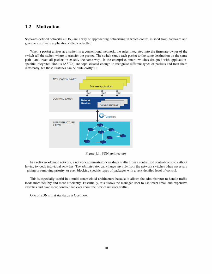
When a packet arrives at a switch in a conventional network, the rules integrated into the firmware owner of theswitch tell the switch where to transfer the packet. The switch sends each packet to the same destination on the samepath - and treats all packets in exactly the same way. In the enterprise, smart switches designed with application-specific integrated circuits (ASICs) are sophisticated enough to recognize different types of packets and treat themdifferently, but these switches can be quite costly.1.1
Figure 1.1: SDN architecture
In a software-defined network, a network administrator can shape traffic from a centralized control console withouthaving to touch individual switches. The administrator can change any rule from the network switches when necessary- giving or removing priority, or even blocking specific types of packages with a very detailed level of control.
This is especially useful in a multi-tenant cloud architecture because it allows the administrator to handle trafficloads more flexibly and more efficiently. Essentially, this allows the managed user to use fewer small and expensiveswitches and have more control than ever about the flow of network traffic.
One of SDN’s first standards is Openflow.
10
1.3 Openflow
OpenFlow (OF) is considered one of the first software-defined networking (SDN) standards. It originally defined thecommunication protocol in SDN environments that enables the SDN Controller to directly interact with the forwardingplane of network devices such as switches and routers, both physical and virtual (hypervisor-based), so it can betteradapt to changing business requirements.
An SDN Controller in SDN is the “brains” of the SDN network, relaying information to switches/routers ‘below’(via southbound APIs) and the applications and business logic ‘above’ (via northbound APIs). Recently, as orga-nizations deploy more SDN networks, SDN Controllers have been tasked with federating between SDN Controllerdomains, using common application interfaces, like OpenFlow and open virtual switch database (OVSDB).
To work in an OF environment, any device that wants to communicate to an SDN Controller must support theOpenFlow protocol. Through this interface, the SDN Controller pushes down changes to the switch/router flow-table allowing network administrators to partition traffic, control flows for optimal performance, and start testing newconfigurations and applications.
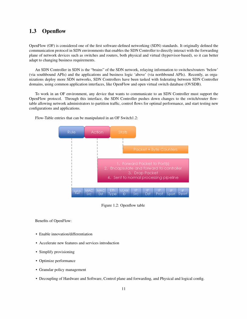
Flow-Table entries that can be manipulated in an OF Switch1.2:
Figure 1.2: Openflow table
Benefits of OpenFlow:
• Enable innovation/differentiation
• Accelerate new features and services introduction
• Simplify provisioning
• Optimize performance
• Granular policy management
• Decoupling of Hardware and Software, Control plane and forwarding, and Physical and logical config.
11
For this project we will use the SDN RYU framework. RYU supports various protocols for managing networkdevices, such as OpenFlow.
1.4 What is RYU Controller?
RYU Controller is an open, software-defined networking (SDN) Controller designed to increase the agility of thenetwork by making it easy to manage and adapt how traffic is handled. In general, the SDN Controller is the brains ofthe SDN environment, communicating information down to the switches and routers with southbound APIs, and up tothe applications and business logic with northbound APIs. The RYU Controller is supported by NTT and is deployedin NTT cloud data centers as well.
The RYU Controller provides software components, with well-defined application program interfaces (APIs), thatmake it easy for developers to create new network management and control applications. This component approachhelps organizations customize deployments to meet their specific needs; developers can quickly and easily modifyexisting components or implement their own to ensure the underlying network can meet the changing demands oftheir applications.
The RYU Controller source code is hosted on GitHub and managed and maintained by the open RYU commu-nity. OpenStack, which runs an open collaboration focused on developing a cloud operating system that can controlthe compute, storage and networking resources of an organization, supports deployments of RYU as the networkController.
Written entirely in Python, all of RYU’s code is available under the Apache 2.0 license and open for anyone touse. The RYU Controller supports NETCONF and OF-config network management protocols, as well as OpenFlow,which is one of the first and most widely deployed SDN communications standards.
The RYU Controller can use OpenFlow to interact with the forwarding plane (switches and routers) to modify howthe network will handle traffic flows. It has been tested and certified to work with a number of OpenFlow switches,including Open vSwitch and offerings from Centec, Hewlett Packard, IBM, and NEC.
12
1.5 VXLAN
1.5.1 Introduction
The Virtual eXtensible Local Area Network (VXLAN) is a solution to build overlay networks within virtualized datacenters accommodating multiple tenants. VXLAN was initially defined by Arista, Broadcom, Cisco, Citrix, and RedHat who joined together to rethink multi-tenancy and segmentation in the cloud datacenter back in 2011. It is importantto remark that a broad range of networking hardware, ASICS, and hypervisor vendors backed the proposal, creatingan opportunity for long-term hardware support and smooth interoperability.
VXLAN defines an overlay to carry the MAC traffic from the individual VMs in an encapsulated format over alogical "tunnel". In short, VXLAN is a Layer 2 overlay scheme on a Layer 3 network. VXLAN uses the L2oL3 schemebecause their authors argue that L3 networks are not a comprehensive solution for multi-tenancy. Two tenants mightuse the same set of Layer 3 addresses within their networks, which requires the cloud provider to provide isolation insome other form. Further, requiring all tenants to use IP excludes customers relying on direct Layer 2 or non-IP Layer3 protocols for inter VM communication.
Each overlay is termed a VXLAN segment or VXLAN overlay network. Only VMs within the same VXLANsegment can communicate with each other. Each VXLAN segment is identified through a 24-bit segment ID, termedthe "VXLAN Network Identifier (VNI)". This allows up to 16 M VXLAN segments to coexist within the sameadministrative domain.
The VNI identifies the scope of the inner MAC frame originated by the individual VM. Thus, you could haveoverlapping MAC addresses across segments but never have traffic "cross over" since the traffic is isolated using theVNI. The VNI is in an outer header that encapsulates the inner MAC frame originated by the VM.
1.5.2 Tunneling
The tunneling in VXLAN is stateless, so each frame is encapsulated according to a set of rules. The end point ofthe tunnel is called VTEP (VXLAN Tunnel End Point). The VNI and VXLAN encapsulation are known only to theVTEP, the VM never sees it.
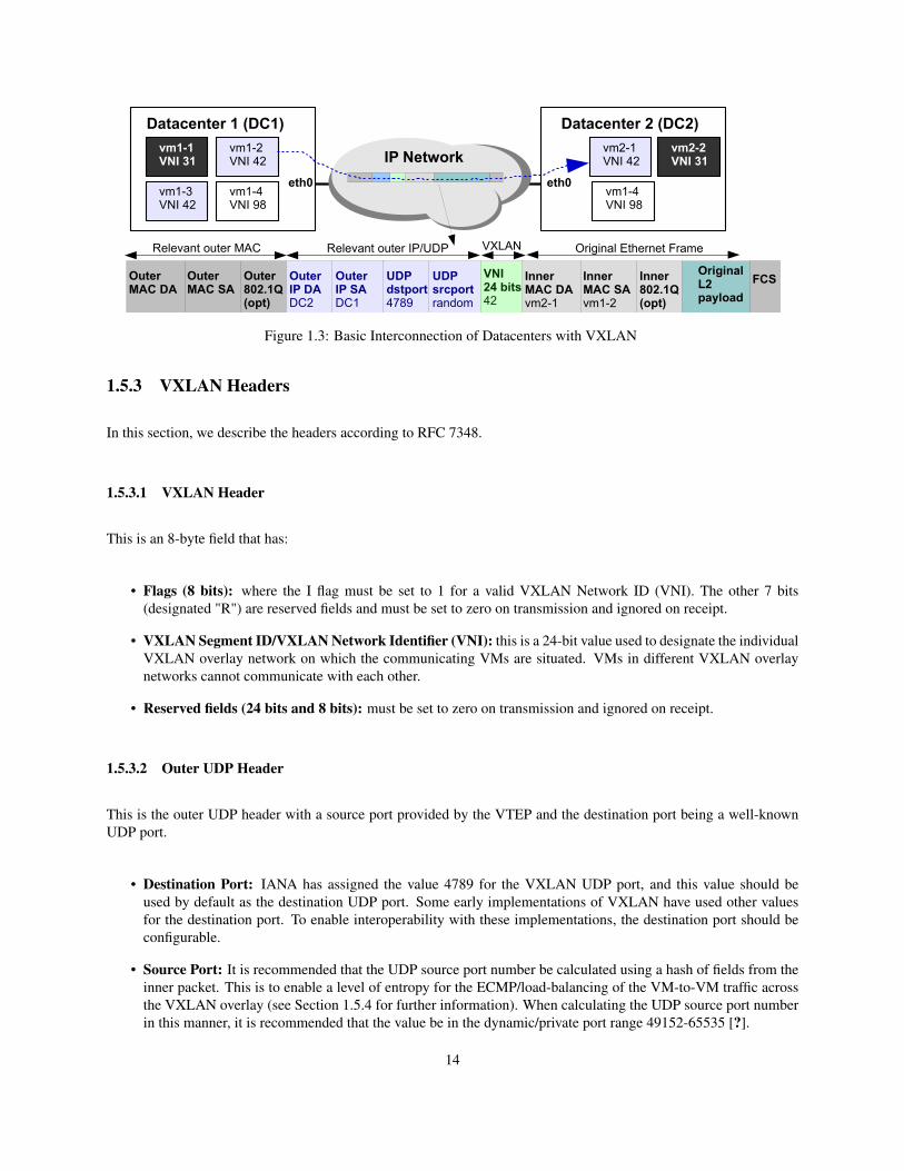
Consider a VM within a VXLAN overlay network (e.g. vm1-2 in Figure 1.3). This VM is unaware of VXLAN. Tocommunicate with a VM on a different datacenter, it sends a MAC frame destined to the target as normal. The VTEPlooks up the VNI to which this VM is associated. It then determines if the destination MAC is on the same segmentand if there is a mapping of the destination MAC address to the remote VTEP. If so, an outer header comprising anouter MAC, outer IP/UDP headers, and VXLAN header are prepended to the original MAC frame. The encapsulatedpacket is forwarded towards the remote VTEP (in our example the VTEP is datacenter 2 as shown in Figure 1.3).
Upon reception, the remote VTEP (datacenter 2) verifies the validity of the VNI and whether or not there is a VMon that VNI using a MAC address that matches the inner destination MAC address. If so, the packet is stripped of itsencapsulating headers and passed on to the destination VM. The destination VM never knows about the VNI or thatthe frame was transported with a VXLAN encapsulation.
13
vm1-1VNI 31 IP Network
vm1-2VNI 42
vm1-3VNI 42
vm1-4VNI 98
Datacenter 1 (DC1)
eth0
vm2-1VNI 42
Datacenter 2 (DC2)
eth0vm1-4VNI 98
vm2-2VNI 31
OuterMAC SA
OuterMAC DA
Outer802.1Q(opt)
Relevant outer MAC
OuterIP DADC2
Relevant outer IP/UDP
OuterIP SADC1
UDPdstport4789
UDPsrcportrandom
VNI24 bits42
VXLAN
InnerMAC SAvm1-2
InnerMAC DAvm2-1
Inner802.1Q(opt)
Original Ethernet Frame
FCSOriginalL2 payload
Figure 1.3: Basic Interconnection of Datacenters with VXLAN
1.5.3 VXLAN Headers
In this section, we describe the headers according to RFC 7348.
1.5.3.1 VXLAN Header
This is an 8-byte field that has:
• Flags (8 bits): where the I flag must be set to 1 for a valid VXLAN Network ID (VNI). The other 7 bits(designated "R") are reserved fields and must be set to zero on transmission and ignored on receipt.
• VXLAN Segment ID/VXLAN Network Identifier (VNI): this is a 24-bit value used to designate the individualVXLAN overlay network on which the communicating VMs are situated. VMs in different VXLAN overlaynetworks cannot communicate with each other.
• Reserved fields (24 bits and 8 bits): must be set to zero on transmission and ignored on receipt.
1.5.3.2 Outer UDP Header
This is the outer UDP header with a source port provided by the VTEP and the destination port being a well-knownUDP port.
• Destination Port: IANA has assigned the value 4789 for the VXLAN UDP port, and this value should beused by default as the destination UDP port. Some early implementations of VXLAN have used other valuesfor the destination port. To enable interoperability with these implementations, the destination port should beconfigurable.
• Source Port: It is recommended that the UDP source port number be calculated using a hash of fields from theinner packet. This is to enable a level of entropy for the ECMP/load-balancing of the VM-to-VM traffic acrossthe VXLAN overlay (see Section 1.5.4 for further information). When calculating the UDP source port numberin this manner, it is recommended that the value be in the dynamic/private port range 49152-65535 [?].
14
• UDP Checksum: It should be transmitted as zero. When a packet is received with a UDP checksum of zero,it must be accepted for decapsulation. Optionally, if the encapsulating end point includes a non-zero UDPchecksum, it must be correctly calculated across the entire packet including the IP header, UDP header, VXLANheader, and encapsulated MAC frame. When a decapsulating end point receives a packet with a non-zerochecksum, it may choose to verify the checksum value. If it chooses to perform such verification, and theverification fails, the packet must be dropped. If the decapsulating destination chooses not to perform theverification, or performs it successfully, the packet must be accepted for decapsulation.
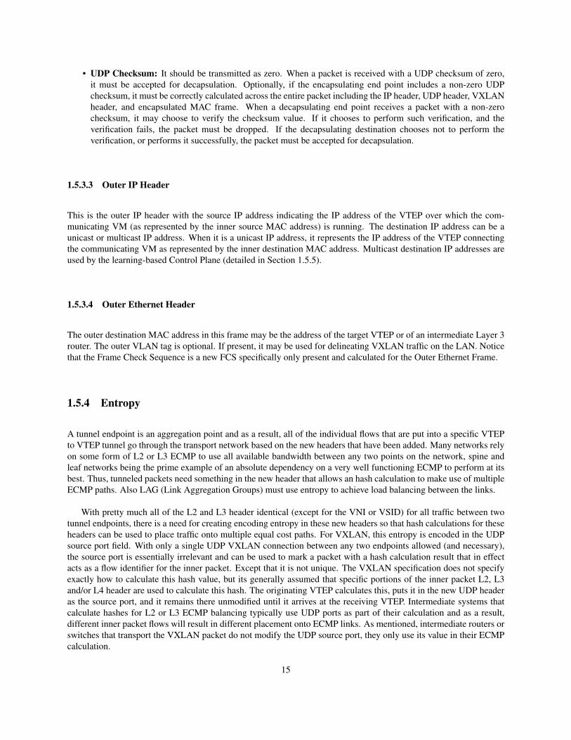
1.5.3.3 Outer IP Header
This is the outer IP header with the source IP address indicating the IP address of the VTEP over which the com-municating VM (as represented by the inner source MAC address) is running. The destination IP address can be aunicast or multicast IP address. When it is a unicast IP address, it represents the IP address of the VTEP connectingthe communicating VM as represented by the inner destination MAC address. Multicast destination IP addresses areused by the learning-based Control Plane (detailed in Section 1.5.5).
1.5.3.4 Outer Ethernet Header
The outer destination MAC address in this frame may be the address of the target VTEP or of an intermediate Layer 3router. The outer VLAN tag is optional. If present, it may be used for delineating VXLAN traffic on the LAN. Noticethat the Frame Check Sequence is a new FCS specifically only present and calculated for the Outer Ethernet Frame.
1.5.4 Entropy
A tunnel endpoint is an aggregation point and as a result, all of the individual flows that are put into a specific VTEPto VTEP tunnel go through the transport network based on the new headers that have been added. Many networks relyon some form of L2 or L3 ECMP to use all available bandwidth between any two points on the network, spine andleaf networks being the prime example of an absolute dependency on a very well functioning ECMP to perform at itsbest. Thus, tunneled packets need something in the new header that allows an hash calculation to make use of multipleECMP paths. Also LAG (Link Aggregation Groups) must use entropy to achieve load balancing between the links.
With pretty much all of the L2 and L3 header identical (except for the VNI or VSID) for all traffic between twotunnel endpoints, there is a need for creating encoding entropy in these new headers so that hash calculations for theseheaders can be used to place traffic onto multiple equal cost paths. For VXLAN, this entropy is encoded in the UDPsource port field. With only a single UDP VXLAN connection between any two endpoints allowed (and necessary),the source port is essentially irrelevant and can be used to mark a packet with a hash calculation result that in effectacts as a flow identifier for the inner packet. Except that it is not unique. The VXLAN specification does not specifyexactly how to calculate this hash value, but its generally assumed that specific portions of the inner packet L2, L3and/or L4 header are used to calculate this hash. The originating VTEP calculates this, puts it in the new UDP headeras the source port, and it remains there unmodified until it arrives at the receiving VTEP. Intermediate systems thatcalculate hashes for L2 or L3 ECMP balancing typically use UDP ports as part of their calculation and as a result,different inner packet flows will result in different placement onto ECMP links. As mentioned, intermediate routers orswitches that transport the VXLAN packet do not modify the UDP source port, they only use its value in their ECMPcalculation.
15
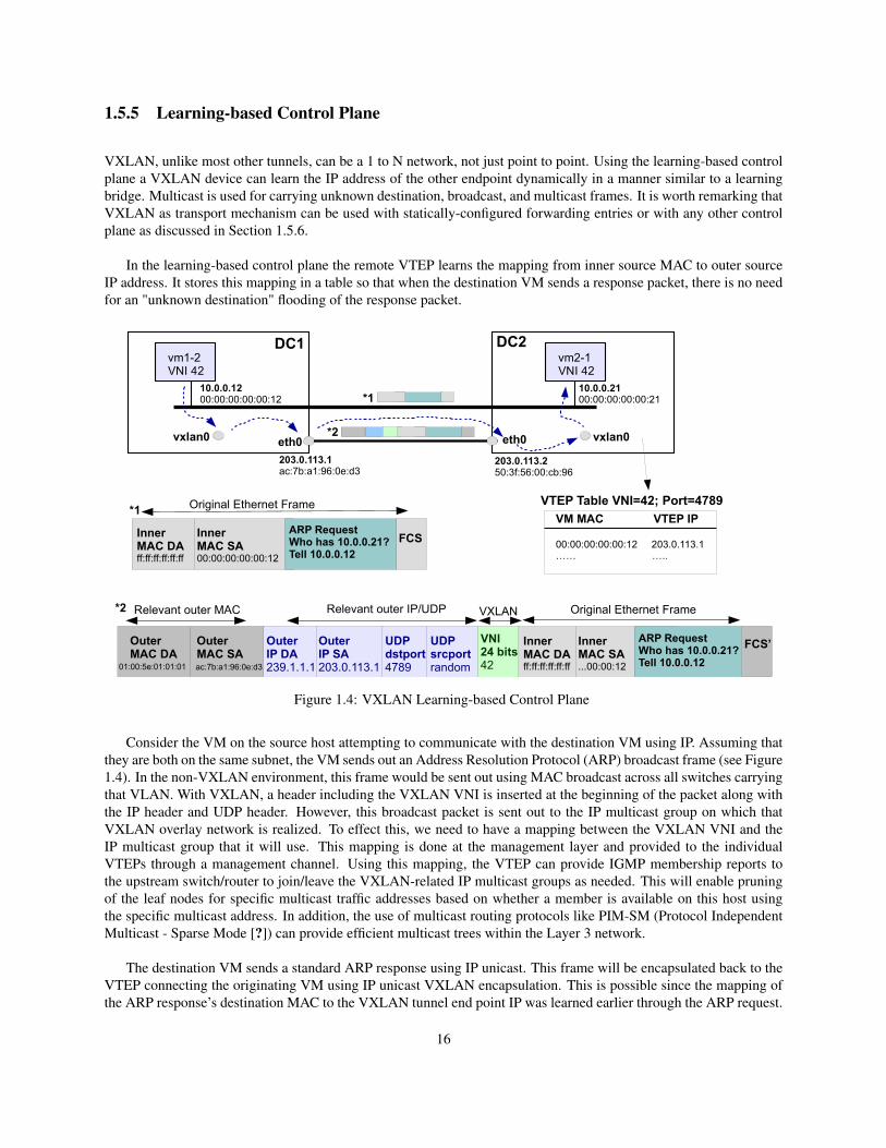
1.5.5 Learning-based Control Plane
VXLAN, unlike most other tunnels, can be a 1 to N network, not just point to point. Using the learning-based controlplane a VXLAN device can learn the IP address of the other endpoint dynamically in a manner similar to a learningbridge. Multicast is used for carrying unknown destination, broadcast, and multicast frames. It is worth remarking thatVXLAN as transport mechanism can be used with statically-configured forwarding entries or with any other controlplane as discussed in Section 1.5.6.
In the learning-based control plane the remote VTEP learns the mapping from inner source MAC to outer sourceIP address. It stores this mapping in a table so that when the destination VM sends a response packet, there is no needfor an "unknown destination" flooding of the response packet.
OuterMAC SA
OuterMAC DA
Relevant outer MAC
OuterIP DA239.1.1.1
Relevant outer IP/UDP
vm1-2VNI 42
DC1
eth0
vm2-1VNI 42
DC2
eth0
OuterIP SA203.0.113.1
UDPdstport4789
UDPsrcportrandom
VNI24 bits42
VXLAN
InnerMAC SA...00:00:12
InnerMAC DAff:ff:ff:ff:ff:ff
Original Ethernet Frame
FCS’
InnerMAC SA00:00:00:00:00:12
InnerMAC DAff:ff:ff:ff:ff:ff
Original Ethernet Frame
ARP RequestWho has 10.0.0.21?Tell 10.0.0.12
FCS
ARP RequestWho has 10.0.0.21?Tell 10.0.0.12
vxlan0
10.0.0.1200:00:00:00:00:12
10.0.0.2100:00:00:00:00:21
ac:7b:a1:96:0e:d301:00:5e:01:01:01
203.0.113.1ac:7b:a1:96:0e:d3
203.0.113.250:3f:56:00:cb:96
vxlan0
*1
*2
*1
*2
VM MAC VTEP IP
00:00:00:00:00:12 203.0.113.1…… …..
VTEP Table VNI=42; Port=4789
Figure 1.4: VXLAN Learning-based Control Plane
Consider the VM on the source host attempting to communicate with the destination VM using IP. Assuming thatthey are both on the same subnet, the VM sends out an Address Resolution Protocol (ARP) broadcast frame (see Figure1.4). In the non-VXLAN environment, this frame would be sent out using MAC broadcast across all switches carryingthat VLAN. With VXLAN, a header including the VXLAN VNI is inserted at the beginning of the packet along withthe IP header and UDP header. However, this broadcast packet is sent out to the IP multicast group on which thatVXLAN overlay network is realized. To effect this, we need to have a mapping between the VXLAN VNI and theIP multicast group that it will use. This mapping is done at the management layer and provided to the individualVTEPs through a management channel. Using this mapping, the VTEP can provide IGMP membership reports tothe upstream switch/router to join/leave the VXLAN-related IP multicast groups as needed. This will enable pruningof the leaf nodes for specific multicast traffic addresses based on whether a member is available on this host usingthe specific multicast address. In addition, the use of multicast routing protocols like PIM-SM (Protocol IndependentMulticast - Sparse Mode [?]) can provide efficient multicast trees within the Layer 3 network.
The destination VM sends a standard ARP response using IP unicast. This frame will be encapsulated back to theVTEP connecting the originating VM using IP unicast VXLAN encapsulation. This is possible since the mapping ofthe ARP response’s destination MAC to the VXLAN tunnel end point IP was learned earlier through the ARP request.
16
Note that multicast frames and "unknown MAC destination" frames are also sent using the multicast tree, similarto the broadcast frames.
VTEPs must not fragment VXLAN packets. Intermediate routers may fragment encapsulated VXLAN packets dueto the larger frame size. The destination VTEP may silently discard such VXLAN fragments. To ensure end-to-endtraffic delivery without fragmentation, it is recommended that the MTUs (Maximum Transmission Units) across thephysical network infrastructure be set to a value that accommodates the larger frame size due to the encapsulation.Other techniques like Path MTU discovery may be used to address this requirement as well.
1.5.6 Other Control Planes
While VXLAN offers a solid data plane solution, the learning-based control plane introduces scaling challenges andthe hardest drawback is that most organizations are reluctant to enable multicast and the large majority of networksdon’t support multicast. The good news is that VXLAN can be used with other control planes for the distribution ofthe VTEP IP to VM MAC mapping information.
One of these control planes is Ethernet VPN (EVPN). EVPN has emerged as a proposal from the telco vendors andoperators to offer a strong end-to-end solution for datacenter VXLAN networks. EVPN uses a new address family,L2VPN EVPN, of Multi-protocol BGP control plane to distribute VXLAN EVPN routes that include both Layer-3Host IP routes and Layer-2 MAC routes. Multi-protocol BGP has a proven track record for operating Internet-scale IPnetworks with multi-tenancy support. In this respect, there have been proposed specifications for a BGP MPLS basedEthernet VPN (RFC 7432) and extensions of RFC 7432 to enable BGP control plane for VXLAN encapsulation.
From the cloud world (from CoreOS) has emerged a simple control plane for VXLAN called flannel [?]. Flannelis getting attraction and being used by container orchestration tools like Kubernetes [?] from Google. Flannel uses acentral directory-based for IP lookup. This central directory is implemented with a distributed key/value store calledetcd.
17
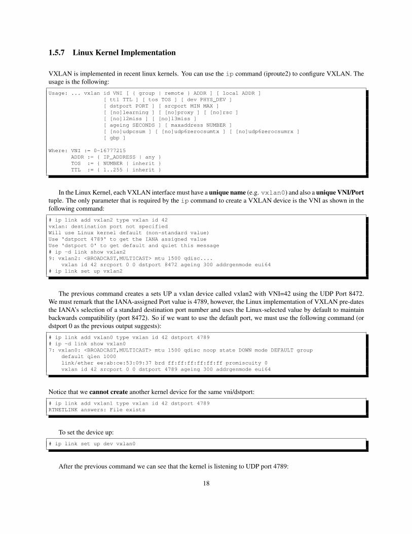
1.5.7 Linux Kernel Implementation
VXLAN is implemented in recent linux kernels. You can use the ip command (iproute2) to configure VXLAN. Theusage is the following:
Usage: ... vxlan id VNI [ { group | remote } ADDR ] [ local ADDR ][ ttl TTL ] [ tos TOS ] [ dev PHYS_DEV ][ dstport PORT ] [ srcport MIN MAX ][ [no]learning ] [ [no]proxy ] [ [no]rsc ][ [no]l2miss ] [ [no]l3miss ][ ageing SECONDS ] [ maxaddress NUMBER ][ [no]udpcsum ] [ [no]udp6zerocsumtx ] [ [no]udp6zerocsumrx ][ gbp ]
Where: VNI := 0-16777215ADDR := { IP_ADDRESS | any }TOS := { NUMBER | inherit }TTL := { 1..255 | inherit }
In the Linux Kernel, each VXLAN interface must have a unique name (e.g. vxlan0) and also a unique VNI/Porttuple. The only parameter that is required by the ip command to create a VXLAN device is the VNI as shown in thefollowing command:
# ip link add vxlan2 type vxlan id 42vxlan: destination port not specifiedWill use Linux kernel default (non-standard value)Use 'dstport 4789' to get the IANA assigned valueUse 'dstport 0' to get default and quiet this message# ip -d link show vxlan29: vxlan2: <BROADCAST,MULTICAST> mtu 1500 qdisc....
vxlan id 42 srcport 0 0 dstport 8472 ageing 300 addrgenmode eui64# ip link set up vxlan2
The previous command creates a sets UP a vxlan device called vxlan2 with VNI=42 using the UDP Port 8472.We must remark that the IANA-assigned Port value is 4789, however, the Linux implementation of VXLAN pre-datesthe IANA’s selection of a standard destination port number and uses the Linux-selected value by default to maintainbackwards compatibility (port 8472). So if we want to use the default port, we must use the following command (ordstport 0 as the previous output suggests):
# ip link add vxlan0 type vxlan id 42 dstport 4789# ip -d link show vxlan07: vxlan0: <BROADCAST,MULTICAST> mtu 1500 qdisc noop state DOWN mode DEFAULT group
default qlen 1000link/ether ee:ab:ce:53:09:37 brd ff:ff:ff:ff:ff:ff promiscuity 0vxlan id 42 srcport 0 0 dstport 4789 ageing 300 addrgenmode eui64
Notice that we cannot create another kernel device for the same vni/dstport:
# ip link add vxlan1 type vxlan id 42 dstport 4789RTNETLINK answers: File exists
To set the device up:
# ip link set up dev vxlan0
After the previous command we can see that the kernel is listening to UDP port 4789:
18
# netstat -ulpActive Internet connections (only servers)Proto Recv-Q Send-Q Local Address ... PID/Program nameudp 0 0 10.0.4.1:domain 149/dnsmasqudp 0 0 *:bootps 149/dnsmasqudp 0 0 *:bootpc 195/dhclientudp 0 0 *:4789 -udp6 0 0 fe80::b40d:15ff::domain 149/dnsmasq
We can create another vxlan device with the same VNI but using another port:
# ip link add vxlan1 type vxlan id 42 dstport 4788
Regarding the UDP source port used in VXLAN encapsulation is random to create entropy for load-balancing(ECMP/LAG). However, the ip command allows us to set a range.
In your Linux box, you can create VXLAN multicast devices and unicast devices and also set static rules forforwarding VXLAN. For example, we can create vxlan multicast device as follows:
# ip link add vxlan0 type vxlan id 42 group 239.1.1.1 dev eth1 dstport 4789
We can show the information of the created vxlan device:
# ip -d link show vxlan010: vxlan0: <BROADCAST,MULTICAST> mtu 1450 qdisc noop state DOWN mode DEFAULT group default...
link/ether 4e:ee:46:10:d7:69 brd ff:ff:ff:ff:ff:ff promiscuity 0vxlan id 42 group 239.1.1.1 dev eth1 srcport 0 0 dstport 4789 ageing 300 addrgenmode eui64
When a vxlan device is configured with multicast, in our example group 239.1.1.1 over eth1, it uses by defaultthe learning-based control plane of VXLAN for unknown destinations. In addition, in our Linux box we can createspecific entries in the VTEP forwarding table using bridge command. For example, to create forwarding table entryfor MAC 00:17:42:8a:b4:05 for a vxlan device:
# bridge fdb add to 00:17:42:8a:b4:05 dst 192.19.0.2 dev vxlan0
The previous command adds an entry for sending to the corresponding MAC address through the device vxlan0,which defines the VNI/dstport in the VXLAN encapsulation. The entry also says that the IP 192.19.0.2 must be usedas outer destination IP address in this VXLAN encapsulation. To delete forwarding table entry:
# bridge fdb delete 00:17:42:8a:b4:05 dev vxlan0
And to show forwarding table:
# bridge fdb show dev vxlan0
We can also create unicast vxlan devices:
# ip link add vxlan1 type vxlan id 42 remote 2.2.2.2 local 1.1.1.1 dev eth1vxlan: destination port not specifiedWill use Linux kernel default (non-standard value)Use 'dstport 4789' to get the IANA assigned valueUse 'dstport 0' to get default and quiet this message
19
When we show the details we can observe these parameters:
# ip -d link show vxlan1...vxlan id 42 remote 2.2.2.2 local 1.1.1.1 dev eth1 srcport 0 0 dstport 8472 ageing 300
In this case, note that we have selected the source and remote IP addresses for sending unicast VXLAN framesthrough vxlan1. Finally, we can delete vxlan device typing:
# ip link delete vxlan0
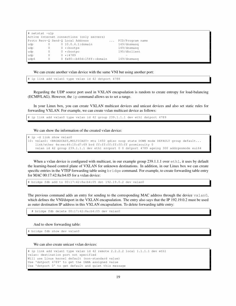
vm1-2VNI 42
DC1
eth0 eth0
10.0.0.1200:00:00:00:00:12
10.0.0.2100:00:00:00:00:21
203.0.113.1ac:7b:a1:96:0e:d3
203.0.113.250:3f:56:00:cb:96
VM MAC VTEP IP
00:00:00:00:00:12 203.0.113.1…… …..
VM MAC VTEP IP
00:00:00:00:00:21 203.0.113.2…… …..
FDB VTEP Table (VNI=42; Port=4789)
br0
vethX
fdb entries
Entries can be dynamic or static with:# bridge fdb ...
FDB VTEP Table (VNI=42; Port=4789)
vm2-1VNI 42
vxlan0(VNI 42)
br0
vethX
DC2
vxlan0(VNI 42)
Figure 1.5: VXLAN & Linux Kernel
In Figure 1.5 we show with some detail the complete process of sending a frame from one VM (vm1-2) in adatacenter (DC1) to another VM (vm2-1) in another datacenter (DC2), considering that we are using the VXLANimplementation of the Linux kernel, i.e. DC1 and DC2 are Linux boxes.
Sending
As shown in Figure 1.5, the vm1-2 in DC1 sends a frame/packet using its MAC/IP addresses. In this case, the VMis using a veth interface that is connected to a kernel bridge called br0. The bridge br0 is who switches the framescomming from vm1-2 to the vxlan device vxlan0. In this case, vxlan0 is using port 4789 and VNI=42. To buildthe vxlan encapsulation, the kernel uses needs:
• The destination port and VNI: these are obtained from the vxlan0 configuration.
• The destination IP address. This is obtained either from the the VTEP FDB (per MAC) or from the vxlandevice configuration (either a unicast or a multicast address).
Then, the VXLAN frame is transmitted to the destination by the Linux Kernel as any other IP packet (selecting sourceMAC and IP).
20
Receiving
The reception of frames by a certain vxlan device is determined by the kernel using the DST port and the VNI presentin the VXLAN encapsulation.
1.5.8 OVS Implementation
Openvswitch is another way of creating and managing VXLAN overlays (and also other overlays) inside a Linuxbox. A first difference between OVS and Kernel implementations is that OVS does not support multicast. Anotherdifference is that in OVS vxlan devices are created inside OVS switches and these devices are not visible by the system.
For example, to create an OVS switch with a vxlan device called vxlan0 inside a switch called br0:
# ovs-vsctl add-br br0# ovs-vsctl add-port br0 vxlan0 -- set Interface vxlan0 type=vxlan \option:remote_ip=203.0.113.2 option:Key=42 ofport_request=10
The previous command creates a vxlan device called vxlan0 connected as port 10 in the OVS switch br0. In thecommand, we have also selected the VNI=42 and the IP address of the destination VTEP. We check this configurationwith:
# ovs-vsctl show29c6ea7c-9d11-40d4-bbb0-d0b23e19dc8a
Bridge "br0"Port "vxlan0"
Interface "vxlan0"type: vxlanoptions: {Key="42", remote_ip="203.0.113.2"}
Port "br0"Interface "br0"
type: internalovs_version: "2.5.0"
If we list the network devices, we will not see any device called vxlan0. However, we will see a vxlan interfacecreated by OVS:
# ip -d link show....11: vxlan_sys_4789: <BROADCAST,MULTICAST,UP,LOWER_UP> mtu 65485 qdisc noqueue master
ovs-system state UNKNOWN mode DEFAULT group default qlen 1000link/ether 62:84:ac:38:ca:8b brd ff:ff:ff:ff:ff:ff promiscuity 1vxlan id 0 srcport 0 0 dstport 4789 nolearning ageing 300 udp6zerocsumrxopenvswitch_slave addrgenmode none
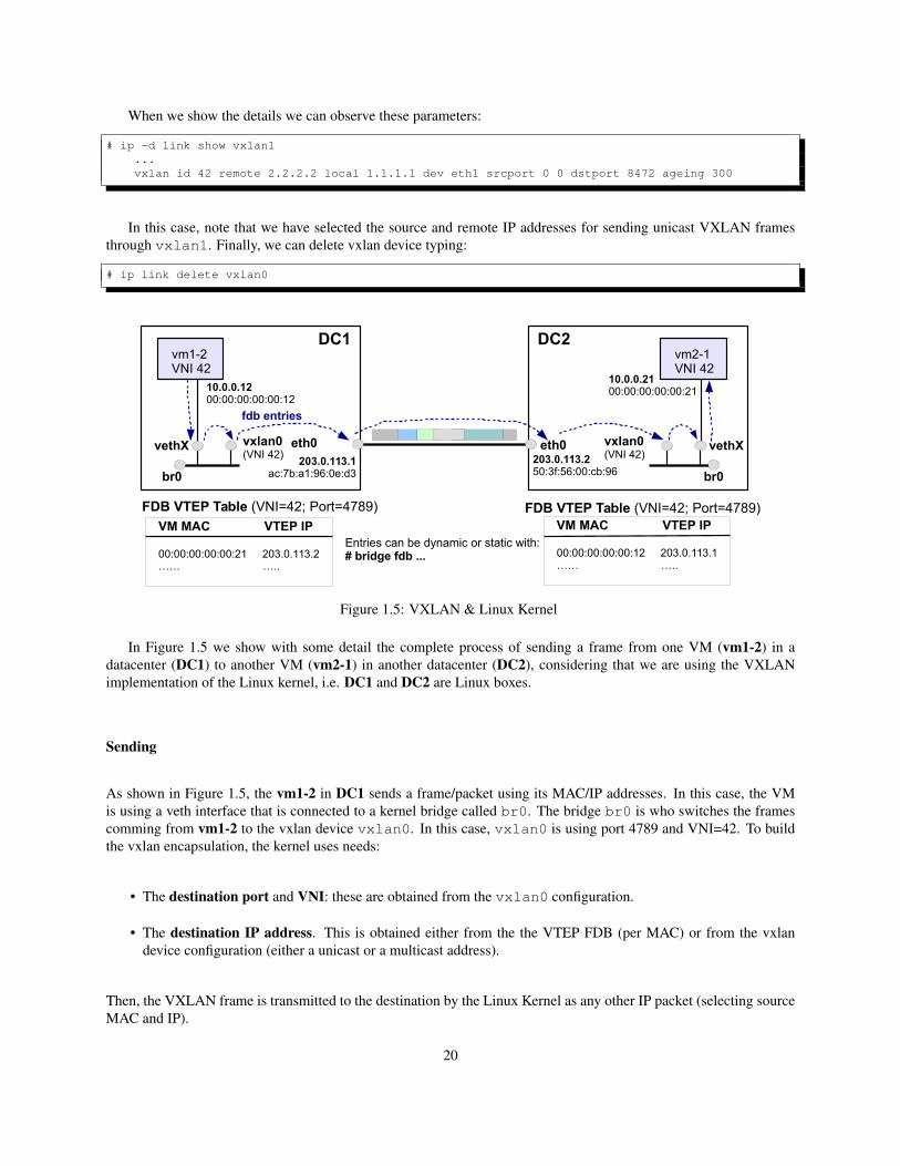
What is happening? As shown in Figure 1.6 OVS creates a ”system vxlan device“ called vxlan_sys_4789 inpromiscuous mode. This interface is created by OVS directly in the Kernel using netlink and it captures all the traffic(all the VNIs) destined to the UDP port 4769. We can also observe that the kernel is listening to UDP port 4769:
# netstat -ulpnActive Internet connections (only servers)Proto Recv-Q Send-Q Local Address Foreign Address State PID/Program name....udp 0 0 0.0.0.0:4789 0.0.0.0:* -....
21
vm1-2
eth0
eth0
br0-p1
veth
vxlan0remote_ip=203.0.113.2
VNI=42
vxlan_sys_4789br0 (OVS)
10
3
Figure 1.6: VXLAN & OVS
As mentioned, OVS uses the device vxlan_sys_4789 to send and receive VXLAN frames of port 4789 whilethe interface vxlan0 is internal to OVS. We can create another vxlan device that uses another UDP port:
# ovs-vsctl add-br br0# ovs-vsctl add-port br0 vxlan1 -- set Interface vxlan1 type=vxlan \option:remote_ip=198.51.100.17 option:Key=42 option:dst_port=9999 ofport_request=11# ovs-vsctl show29c6ea7c-9d11-40d4-bbb0-d0b23e19dc8a
Bridge "br0"Port "vxlan1"
Interface "vxlan1"type: vxlanoptions: {Key="42", dst_port="9999", remote_ip="198.51.100.17"}
Port "vxlan0"Interface "vxlan0"
type: vxlanoptions: {Key="42", dst_port="9999", remote_ip="203.0.113.2"}
Port "br0"Interface "br0"
type: internalovs_version: "2.5.0"
In this case, OVS creates another system device called vxlan_sys_9999 to send and receive all the VXLANtraffic that uses port 9999. We can create vxlan interfaces without specifying the VNI and in this case VNI=0 is used.You can also specify the local IP, for example, options:local_ip=203.0.113.1.
Finally, it is worth to mention that if you try to set up a kernel vxlan device in the same port as one already runningfor OVS (vxlan_sys_xxxx) you will get an error message:
# ip link set up vxlan0RTNETLINK answers: Address already in use
Only one vxlan device per port is allowed in the system.
Flow-based Forwarding
In OVS we can define flow-based forwarding involving VXLAN devices. It is remarkable that OVS flow-basedforwarding is much more flexible and allows us much more low level control of which traffic is sent over the VXLANdevice than the Kernel implementation. For example:
22
# ovs-ofctl add-flow br0 "table=0,tun_id=100,dl_dst=00:00:00:00:00:01,actions=output:1"
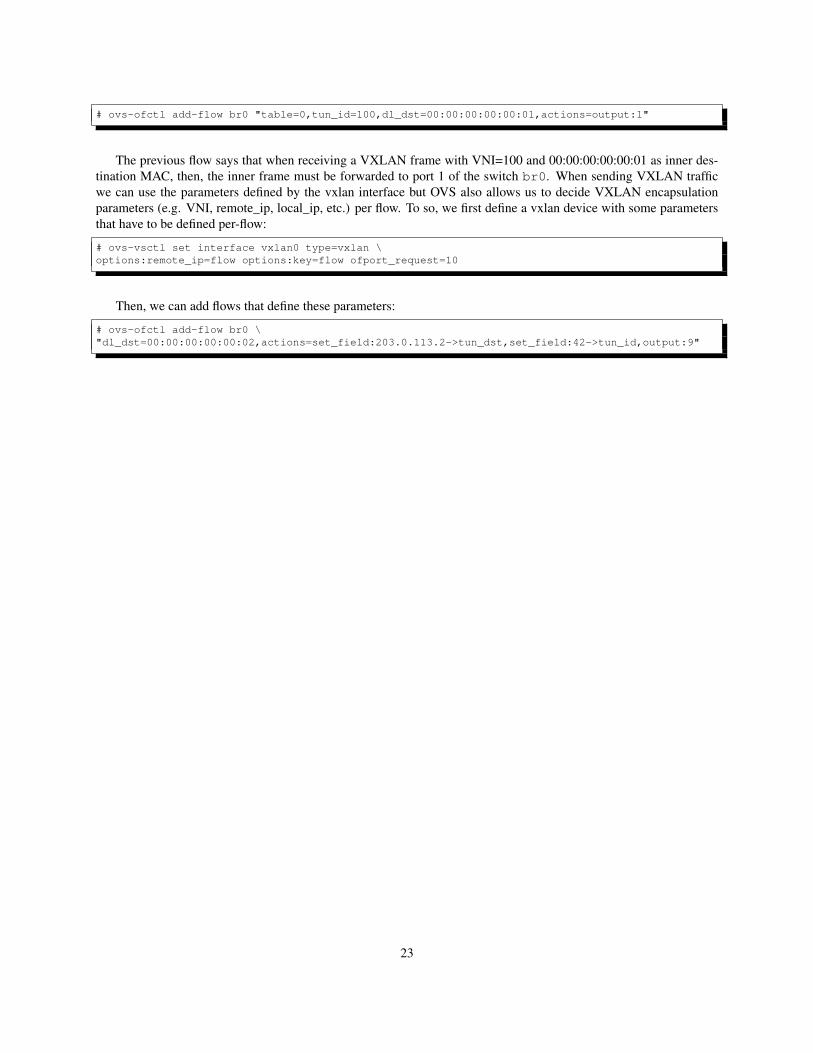
The previous flow says that when receiving a VXLAN frame with VNI=100 and 00:00:00:00:00:01 as inner des-tination MAC, then, the inner frame must be forwarded to port 1 of the switch br0. When sending VXLAN trafficwe can use the parameters defined by the vxlan interface but OVS also allows us to decide VXLAN encapsulationparameters (e.g. VNI, remote_ip, local_ip, etc.) per flow. To so, we first define a vxlan device with some parametersthat have to be defined per-flow:
# ovs-vsctl set interface vxlan0 type=vxlan \options:remote_ip=flow options:key=flow ofport_request=10
Then, we can add flows that define these parameters:
# ovs-ofctl add-flow br0 \"dl_dst=00:00:00:00:00:02,actions=set_field:203.0.113.2->tun_dst,set_field:42->tun_id,output:9"
23

24
Chapter 2
Network and Topology set up
2.1 Description
The system is designed to enable L2 communication among VMs of the same tenant hosted on different serversor vtep’s. The servers are connected over L3 Network. Only those VMs within the same VXLAN segment cancommunicate with each other. One VM will belong to only one tenant.
A VM is uniquely identified by (MAC, VNI) pair, i.e. two different VMs of different tenants can have same MACaddresses but two VMs of the same tenant cannot.
Some server nodes are on networks that are VXLAN aware. For such servers, the VXLAN tunnel endpoint iscreated on the OVS at the server itself which will have mapping of Port number to VNIs.
All the OVS that act as tunnel endpoints are connected to a controller. This controller will push rules (usingOpenFlow protocol) for forwarding traffic to remote tunnel endpoints.
25
2.2 Overview
2.2.1 Scenario
Let’s see a schematic drawing of the complete scenario 2.1:
10.0.0.2 10.0.0.2 10.0.0.2 10.0.0.12
15.0.0.2
Server2
1 2 43
10.0.0.3 10.0.0.3 10.0.0.3 10.0.013
13.0.0.2
Server3
1 2 43
10.0.0.1 10.0.0.1 10.0.0.1 10.0.0.11
14.0.0.2
Server1
1 2 43
Ip:16.0.0.2Port: 6633OVSDB Port: 6640
Ryu ControllerVNI:1001
VNI:1002
VNI:1003
Tunnel VxlanOfPort: 10 Tunnel Vxlan
OfPort: 11
Figure 2.1: VXLAN scenario
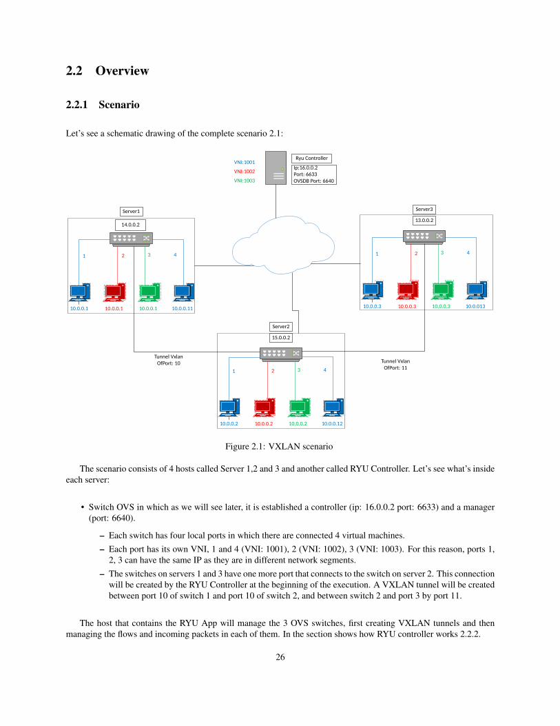
The scenario consists of 4 hosts called Server 1,2 and 3 and another called RYU Controller. Let’s see what’s insideeach server:
• Switch OVS in which as we will see later, it is established a controller (ip: 16.0.0.2 port: 6633) and a manager(port: 6640).
– Each switch has four local ports in which there are connected 4 virtual machines.– Each port has its own VNI, 1 and 4 (VNI: 1001), 2 (VNI: 1002), 3 (VNI: 1003). For this reason, ports 1,
2, 3 can have the same IP as they are in different network segments.– The switches on servers 1 and 3 have one more port that connects to the switch on server 2. This connection
will be created by the RYU Controller at the beginning of the execution. A VXLAN tunnel will be createdbetween port 10 of switch 1 and port 10 of switch 2, and between switch 2 and port 3 by port 11.
The host that contains the RYU App will manage the 3 OVS switches, first creating VXLAN tunnels and thenmanaging the flows and incoming packets in each of them. In the section shows how RYU controller works 2.2.2.
26
2.2.2 RYU controller
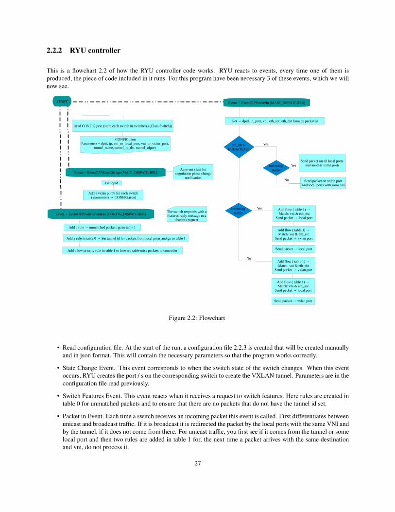
This is a flowchart 2.2 of how the RYU controller code works. RYU reacts to events, every time one of them isproduced, the piece of code included in it runs. For this program have been necessary 3 of these events, which we willnow see.
START
Read CONFIG.json (store each switch in switches() (Class Switch))
Add a rule → unmatched packets go to table 1
CONFIG.jsonParameters→dpid, ip, vni_to_local_port, vni_to_vxlan_port,
tunnel_name, tunnel_ip_dst, tunnel_ofport
Event→ EventOFPStateChange (MAIN_DISPATCHER)
Event→ EventOFPSwitchFeatures (CONFIG_DISPATCHER)
Event→ EventOFPPacketIn (MAIN_DISPATCHER)
An event class for negotiation phase change
notification
Get dpid
Add a vxlan port/s for each switch ( parameters → CONFIG.json)
Add a rule in table 0 → Set tunnel id for packets from local ports and go to table 1
Add a low priority rule in table 1 to forward table-miss packets to controller
The switch responds with a features reply message to a
features request
Get → dpid, in_port, vni, eth_src, eth_dst from de packet in
eth_dst is BROADCAST
Incoming traffic
Send packet on all local ports and another vxlan ports
Send packet on vxlan portAnd local ports with same vni
Yes
No
Yes
Incoming traffic
Add flow ( table 1) →Match: vni & eth_dst
Send packet → local port
Add flow ( table 1) →Match: vni & eth_src
Send packet → vxlan port
Send packet → local port
Yes
Add flow ( table 1) →Match: vni & eth_dst
Send packet → vxlan port
Add flow ( table 1) →Match: vni & eth_src
Send packet → local port
Send packet → vxlan port
No
Figure 2.2: Flowchart
• Read configuration file. At the start of the run, a configuration file 2.2.3 is created that will be created manuallyand in json format. This will contain the necessary parameters so that the program works correctly.
• State Change Event. This event corresponds to when the switch state of the switch changes. When this eventoccurs, RYU creates the port / s on the corresponding switch to create the VXLAN tunnel. Parameters are in theconfiguration file read previously.
• Switch Features Event. This event reacts when it receives a request to switch features. Here rules are created intable 0 for unmatched packets and to ensure that there are no packets that do not have the tunnel id set.
• Packet in Event. Each time a switch receives an incoming packet this event is called. First differentiates betweenunicast and broadcast traffic. If it is broadcast it is redirected the packet by the local ports with the same VNI andby the tunnel, if it does not come from there. For unicast traffic, you first see if it comes from the tunnel or somelocal port and then two rules are added in table 1 for, the next time a packet arrives with the same destinationand vni, do not process it.
27
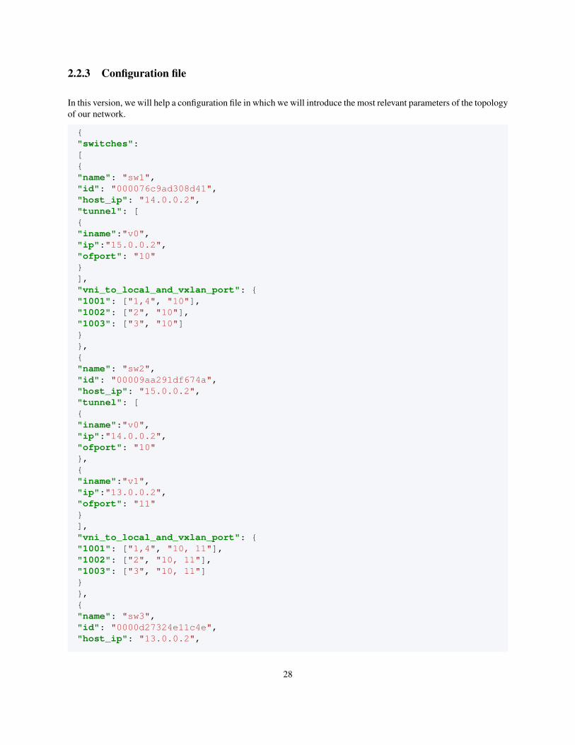
2.2.3 Configuration file
In this version, we will help a configuration file in which we will introduce the most relevant parameters of the topologyof our network.
{"switches":[{"name": "sw1","id": "000076c9ad308d41","host_ip": "14.0.0.2","tunnel": [{"iname":"v0","ip":"15.0.0.2","ofport": "10"}],"vni_to_local_and_vxlan_port": {"1001": ["1,4", "10"],"1002": ["2", "10"],"1003": ["3", "10"]}},{"name": "sw2","id": "00009aa291df674a","host_ip": "15.0.0.2","tunnel": [{"iname":"v0","ip":"14.0.0.2","ofport": "10"},{"iname":"v1","ip":"13.0.0.2","ofport": "11"}],"vni_to_local_and_vxlan_port": {"1001": ["1,4", "10, 11"],"1002": ["2", "10, 11"],"1003": ["3", "10, 11"]}},{"name": "sw3","id": "0000d27324e11c4e","host_ip": "13.0.0.2",
28
"tunnel": [{"iname":"v1","ip":"15.0.0.2","ofport": "11"}],"vni_to_local_and_vxlan_port": {"1001": ["1,4", "11"],"1002": ["2", "11"],"1003": ["3", "11"]}}]}
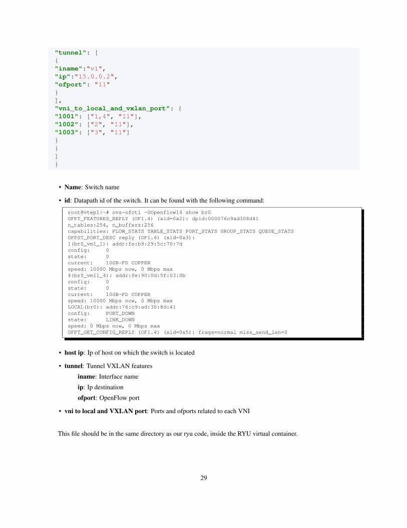
• Name: Switch name
• id: Datapath id of the switch. It can be found with the following command:
root@vtep1:~# ovs-ofctl -OOpenflow14 show br0OFPT_FEATURES_REPLY (OF1.4) (xid=0x2): dpid:000076c9ad308d41n_tables:254, n_buffers:256capabilities: FLOW_STATS TABLE_STATS PORT_STATS GROUP_STATS QUEUE_STATSOFPST_PORT_DESC reply (OF1.4) (xid=0x3):1(br0_vm1_1): addr:fe:b9:29:5c:70:7dconfig: 0state: 0current: 10GB-FD COPPERspeed: 10000 Mbps now, 0 Mbps max4(br0_vm11_4): addr:fe:90:0d:5f:03:0bconfig: 0state: 0current: 10GB-FD COPPERspeed: 10000 Mbps now, 0 Mbps maxLOCAL(br0): addr:76:c9:ad:30:8d:41config: PORT_DOWNstate: LINK_DOWNspeed: 0 Mbps now, 0 Mbps maxOFPT_GET_CONFIG_REPLY (OF1.4) (xid=0x5): frags=normal miss_send_len=0
• host ip: Ip of host on which the switch is located
• tunnel: Tunnel VXLAN features
iname: Interface name
ip: Ip destination
ofport: OpenFlow port
• vni to local and VXLAN port: Ports and ofports related to each VNI
This file should be in the same directory as our ryu code, inside the RYU virtual container.
29
2.3 LXC
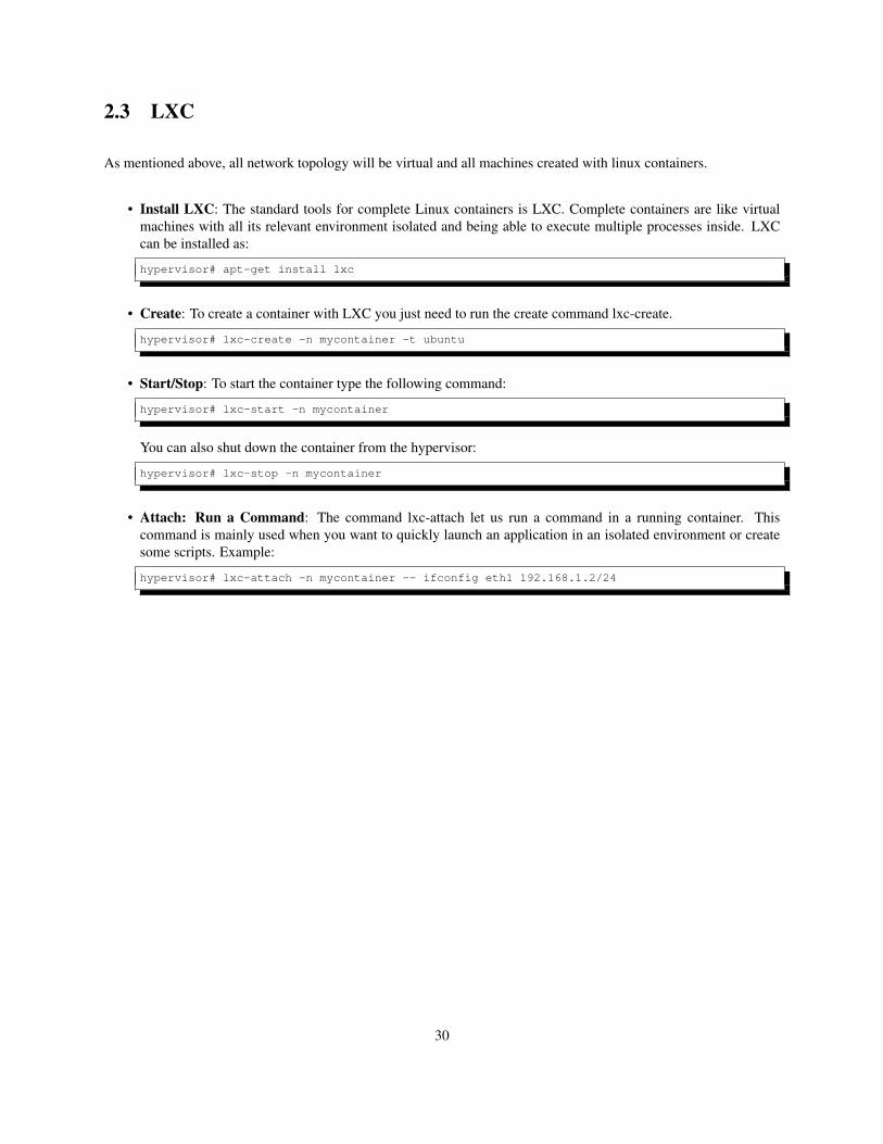
As mentioned above, all network topology will be virtual and all machines created with linux containers.
• Install LXC: The standard tools for complete Linux containers is LXC. Complete containers are like virtualmachines with all its relevant environment isolated and being able to execute multiple processes inside. LXCcan be installed as:
hypervisor# apt-get install lxc
• Create: To create a container with LXC you just need to run the create command lxc-create.
hypervisor# lxc-create -n mycontainer -t ubuntu
• Start/Stop: To start the container type the following command:
hypervisor# lxc-start -n mycontainer
You can also shut down the container from the hypervisor:
hypervisor# lxc-stop -n mycontainer
• Attach: Run a Command: The command lxc-attach let us run a command in a running container. Thiscommand is mainly used when you want to quickly launch an application in an isolated environment or createsome scripts. Example:
hypervisor# lxc-attach -n mycontainer -- ifconfig eth1 192.168.1.2/24
30
2.4 Steps
Now we will see the steps to create the scenario described above.
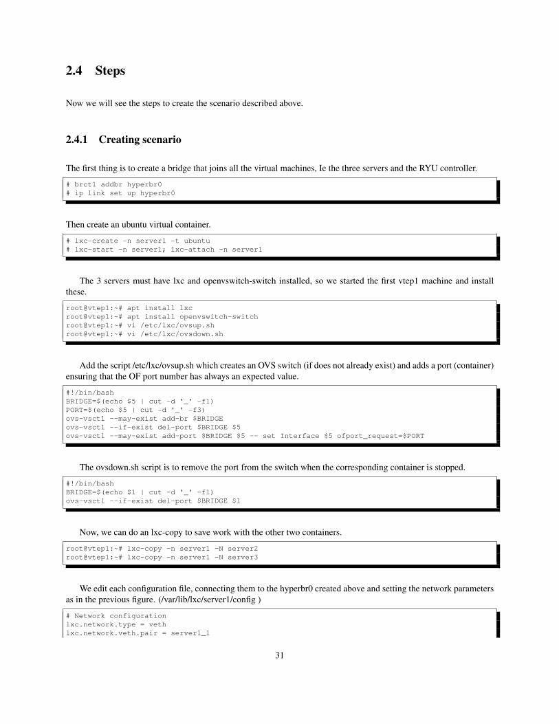
2.4.1 Creating scenario
The first thing is to create a bridge that joins all the virtual machines, Ie the three servers and the RYU controller.
# brctl addbr hyperbr0# ip link set up hyperbr0
Then create an ubuntu virtual container.
# lxc-create -n server1 -t ubuntu# lxc-start -n server1; lxc-attach -n server1
The 3 servers must have lxc and openvswitch-switch installed, so we started the first vtep1 machine and installthese.
root@vtep1:~# apt install lxcroot@vtep1:~# apt install openvswitch-switchroot@vtep1:~# vi /etc/lxc/ovsup.shroot@vtep1:~# vi /etc/lxc/ovsdown.sh
Add the script /etc/lxc/ovsup.sh which creates an OVS switch (if does not already exist) and adds a port (container)ensuring that the OF port number has always an expected value.
#!/bin/bashBRIDGE=$(echo $5 | cut -d '_' -f1)PORT=$(echo $5 | cut -d '_' -f3)ovs-vsctl --may-exist add-br $BRIDGEovs-vsctl --if-exist del-port $BRIDGE $5ovs-vsctl --may-exist add-port $BRIDGE $5 -- set Interface $5 ofport_request=$PORT
The ovsdown.sh script is to remove the port from the switch when the corresponding container is stopped.
#!/bin/bashBRIDGE=$(echo $1 | cut -d '_' -f1)ovs-vsctl --if-exist del-port $BRIDGE $1
Now, we can do an lxc-copy to save work with the other two containers.
root@vtep1:~# lxc-copy -n server1 -N server2root@vtep1:~# lxc-copy -n server1 -N server3
We edit each configuration file, connecting them to the hyperbr0 created above and setting the network parametersas in the previous figure. (/var/lib/lxc/server1/config )
# Network configurationlxc.network.type = vethlxc.network.veth.pair = server1_1
31
lxc.network.link = hyperbr0lxc.network.flags = uplxc.network.hwaddr = 00:00:00:00:dc:01lxc.network.ipv4 = 14.0.0.2/24lxc.network.mtu = 1450
And we do the same with the other two servers.
Now inside each server we create lightweight busybox containers.
# lxc-start -n server1; lxc-attatch -n server1root@vtep1:~# lxc-create -n vm10 -t busyboxroot@vtep1:~# lxc-create -n vm1 -t busyboxroot@vtep1:~# lxc-create -n vm2 -t busyboxroot@vtep1:~# lxc-create -n vm3 -t busybox
And we edit its configuration, including the ovsup.sh and ovsdown.sh scripts.
lxc.network.type = veth#lxc.network.link = ovsbr0lxc.network.veth.pair = br0_vm1_1lxc.network.flags = uplxc.network.hwaddr = 00:00:00:00:00:01lxc.network.ipv4 = 10.0.0.1/24lxc.network.mtu = 1450lxc.network.script.up = /etc/lxc/ovsup.shlxc.hook.post-stop = /etc/lxc/ovsdown.sh br0_vm1_1
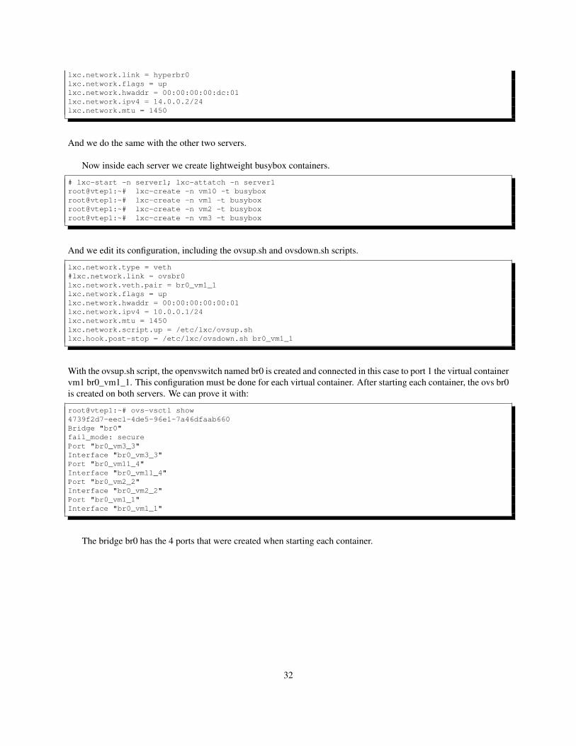
With the ovsup.sh script, the openvswitch named br0 is created and connected in this case to port 1 the virtual containervm1 br0_vm1_1. This configuration must be done for each virtual container. After starting each container, the ovs br0is created on both servers. We can prove it with:
root@vtep1:~# ovs-vsctl show4739f2d7-eec1-4de5-96e1-7a46dfaab660Bridge "br0"fail_mode: securePort "br0_vm3_3"Interface "br0_vm3_3"Port "br0_vm11_4"Interface "br0_vm11_4"Port "br0_vm2_2"Interface "br0_vm2_2"Port "br0_vm1_1"Interface "br0_vm1_1"
The bridge br0 has the 4 ports that were created when starting each container.
32
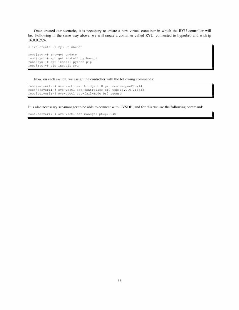
Once created our scenario, it is necessary to create a new virtual container in which the RYU controller willbe. Following in the same way above, we will create a container called RYU, connected to hyperbr0 and with ip16.0.0.2/24.
# lxc-create -n ryu -t ubuntu
root@ryu:~# apt-get updateroot@ryu:~# apt get install python-piroot@ryu:~# apt install python-piproot@ryu:~# pip install ryu
Now, on each switch, we assign the controller with the following commands:
root@server1:~# ovs-vsctl set bridge br0 protocols=OpenFlow14root@server1:~# ovs-vsctl set-controller br0 tcp:16.0.0.2:6633root@server1:~# ovs-vsctl set-fail-mode br0 secure
It is also necessary set-manager to be able to connect with OVSDB, and for this we use the following command:
root@server1:~# ovs-vsctl set-manager ptcp:6640
33

34
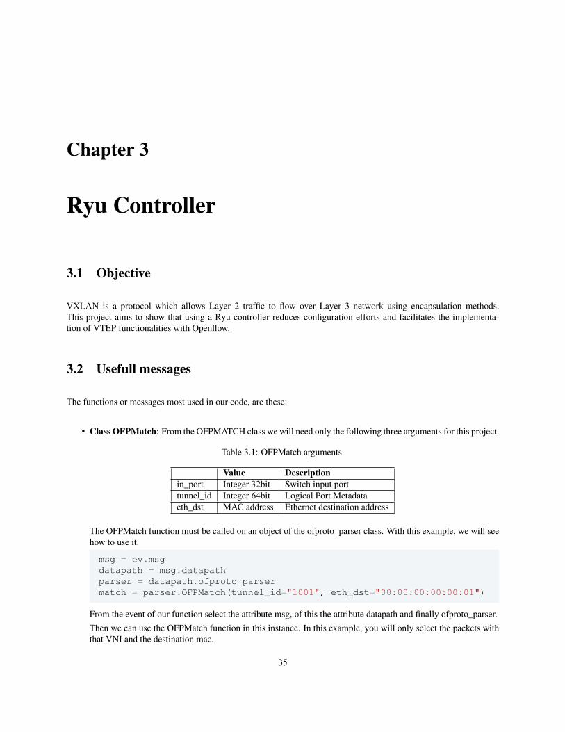
Chapter 3
Ryu Controller
3.1 Objective
VXLAN is a protocol which allows Layer 2 traffic to flow over Layer 3 network using encapsulation methods.This project aims to show that using a Ryu controller reduces configuration efforts and facilitates the implementa-tion of VTEP functionalities with Openflow.
3.2 Usefull messages
The functions or messages most used in our code, are these:
• Class OFPMatch: From the OFPMATCH class we will need only the following three arguments for this project.
Table 3.1: OFPMatch arguments
Value Descriptionin_port Integer 32bit Switch input porttunnel_id Integer 64bit Logical Port Metadataeth_dst MAC address Ethernet destination address
The OFPMatch function must be called on an object of the ofproto_parser class. With this example, we will seehow to use it.
msg = ev.msgdatapath = msg.datapathparser = datapath.ofproto_parsermatch = parser.OFPMatch(tunnel_id="1001", eth_dst="00:00:00:00:00:01")
From the event of our function select the attribute msg, of this the attribute datapath and finally ofproto_parser.
Then we can use the OFPMatch function in this instance. In this example, you will only select the packets withthat VNI and the destination mac.
35
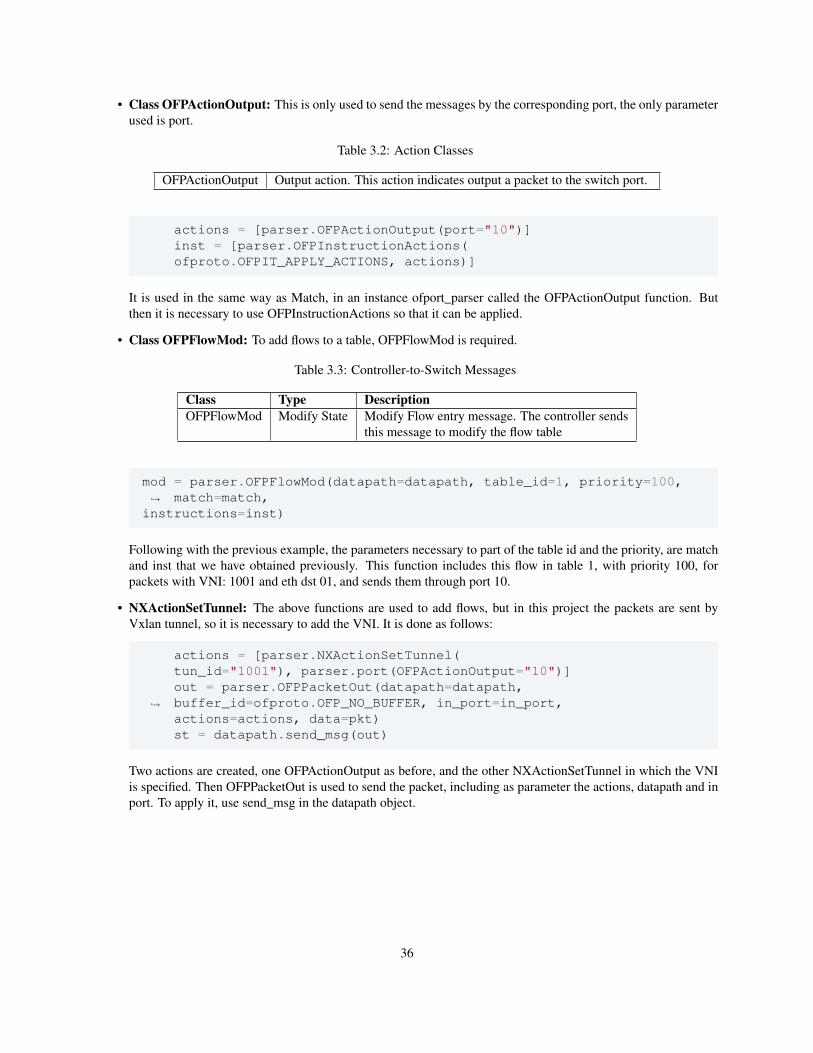
• Class OFPActionOutput: This is only used to send the messages by the corresponding port, the only parameterused is port.
Table 3.2: Action Classes
OFPActionOutput Output action. This action indicates output a packet to the switch port.
actions = [parser.OFPActionOutput(port="10")]inst = [parser.OFPInstructionActions(ofproto.OFPIT_APPLY_ACTIONS, actions)]
It is used in the same way as Match, in an instance ofport_parser called the OFPActionOutput function. Butthen it is necessary to use OFPInstructionActions so that it can be applied.
• Class OFPFlowMod: To add flows to a table, OFPFlowMod is required.
Table 3.3: Controller-to-Switch Messages
Class Type DescriptionOFPFlowMod Modify State Modify Flow entry message. The controller sends
this message to modify the flow table
mod = parser.OFPFlowMod(datapath=datapath, table_id=1, priority=100,match=match,↪→
instructions=inst)
Following with the previous example, the parameters necessary to part of the table id and the priority, are matchand inst that we have obtained previously. This function includes this flow in table 1, with priority 100, forpackets with VNI: 1001 and eth dst 01, and sends them through port 10.
• NXActionSetTunnel: The above functions are used to add flows, but in this project the packets are sent byVxlan tunnel, so it is necessary to add the VNI. It is done as follows:
actions = [parser.NXActionSetTunnel(tun_id="1001"), parser.port(OFPActionOutput="10")]out = parser.OFPPacketOut(datapath=datapath,buffer_id=ofproto.OFP_NO_BUFFER, in_port=in_port,↪→
actions=actions, data=pkt)st = datapath.send_msg(out)
Two actions are created, one OFPActionOutput as before, and the other NXActionSetTunnel in which the VNIis specified. Then OFPPacketOut is used to send the packet, including as parameter the actions, datapath and inport. To apply it, use send_msg in the datapath object.
36
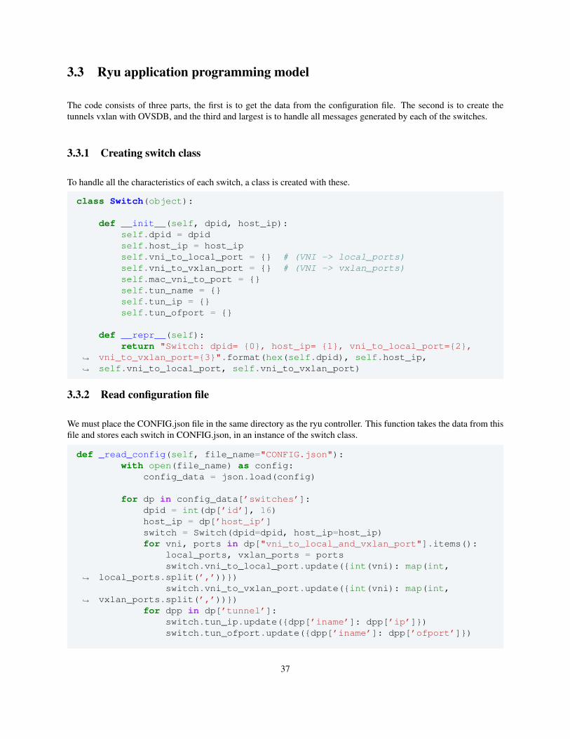
3.3 Ryu application programming model
The code consists of three parts, the first is to get the data from the configuration file. The second is to create thetunnels vxlan with OVSDB, and the third and largest is to handle all messages generated by each of the switches.
3.3.1 Creating switch class
To handle all the characteristics of each switch, a class is created with these.
class Switch(object):
def __init__(self, dpid, host_ip):self.dpid = dpidself.host_ip = host_ipself.vni_to_local_port = {} # (VNI -> local_ports)self.vni_to_vxlan_port = {} # (VNI -> vxlan_ports)self.mac_vni_to_port = {}self.tun_name = {}self.tun_ip = {}self.tun_ofport = {}
def __repr__(self):return "Switch: dpid= {0}, host_ip= {1}, vni_to_local_port={2},
vni_to_vxlan_port={3}".format(hex(self.dpid), self.host_ip,self.vni_to_local_port, self.vni_to_vxlan_port)
↪→
↪→
3.3.2 Read configuration file
We must place the CONFIG.json file in the same directory as the ryu controller. This function takes the data from thisfile and stores each switch in CONFIG.json, in an instance of the switch class.
def _read_config(self, file_name="CONFIG.json"):with open(file_name) as config:
config_data = json.load(config)
for dp in config_data[’switches’]:dpid = int(dp[’id’], 16)host_ip = dp[’host_ip’]switch = Switch(dpid=dpid, host_ip=host_ip)for vni, ports in dp["vni_to_local_and_vxlan_port"].items():
local_ports, vxlan_ports = portsswitch.vni_to_local_port.update({int(vni): map(int,
local_ports.split(’,’))})↪→
switch.vni_to_vxlan_port.update({int(vni): map(int,vxlan_ports.split(’,’))})↪→
for dpp in dp[’tunnel’]:switch.tun_ip.update({dpp[’iname’]: dpp[’ip’]})switch.tun_ofport.update({dpp[’iname’]: dpp[’ofport’]})
37
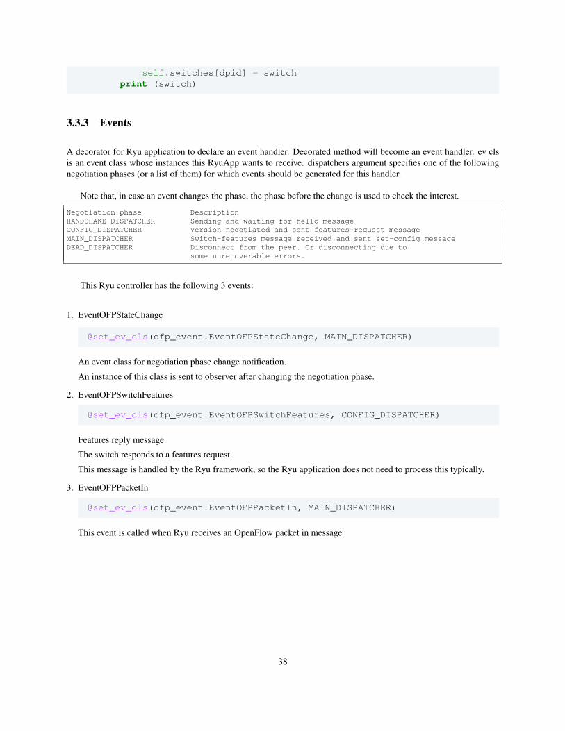
self.switches[dpid] = switchprint (switch)
3.3.3 Events
A decorator for Ryu application to declare an event handler. Decorated method will become an event handler. ev clsis an event class whose instances this RyuApp wants to receive. dispatchers argument specifies one of the followingnegotiation phases (or a list of them) for which events should be generated for this handler.
Note that, in case an event changes the phase, the phase before the change is used to check the interest.
Negotiation phase DescriptionHANDSHAKE_DISPATCHER Sending and waiting for hello messageCONFIG_DISPATCHER Version negotiated and sent features-request messageMAIN_DISPATCHER Switch-features message received and sent set-config messageDEAD_DISPATCHER Disconnect from the peer. Or disconnecting due to
some unrecoverable errors.
This Ryu controller has the following 3 events:
1. EventOFPStateChange
@set_ev_cls(ofp_event.EventOFPStateChange, MAIN_DISPATCHER)
An event class for negotiation phase change notification.
An instance of this class is sent to observer after changing the negotiation phase.
2. EventOFPSwitchFeatures
@set_ev_cls(ofp_event.EventOFPSwitchFeatures, CONFIG_DISPATCHER)
Features reply message
The switch responds to a features request.
This message is handled by the Ryu framework, so the Ryu application does not need to process this typically.
3. EventOFPPacketIn
@set_ev_cls(ofp_event.EventOFPPacketIn, MAIN_DISPATCHER)
This event is called when Ryu receives an OpenFlow packet in message
38
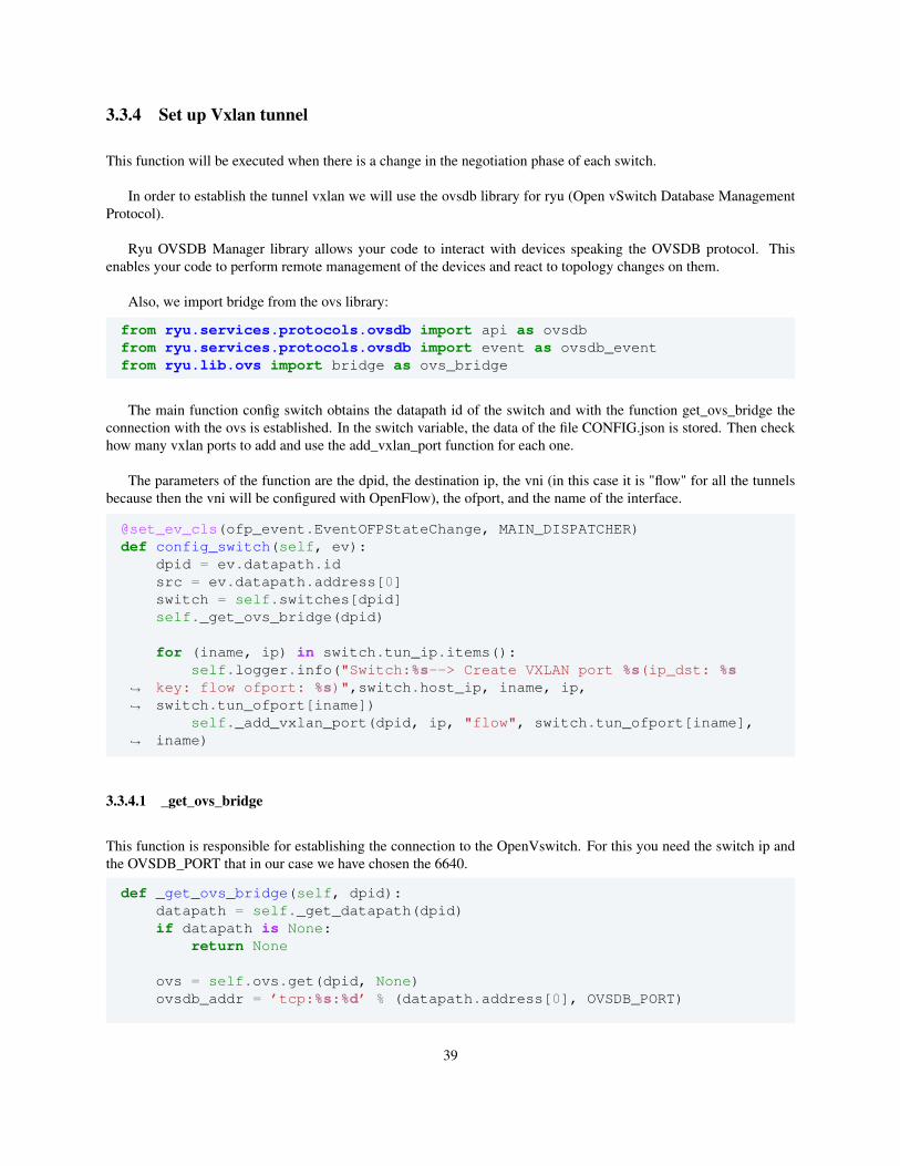
3.3.4 Set up Vxlan tunnel
This function will be executed when there is a change in the negotiation phase of each switch.
In order to establish the tunnel vxlan we will use the ovsdb library for ryu (Open vSwitch Database ManagementProtocol).
Ryu OVSDB Manager library allows your code to interact with devices speaking the OVSDB protocol. Thisenables your code to perform remote management of the devices and react to topology changes on them.
Also, we import bridge from the ovs library:
from ryu.services.protocols.ovsdb import api as ovsdbfrom ryu.services.protocols.ovsdb import event as ovsdb_eventfrom ryu.lib.ovs import bridge as ovs_bridge
The main function config switch obtains the datapath id of the switch and with the function get_ovs_bridge theconnection with the ovs is established. In the switch variable, the data of the file CONFIG.json is stored. Then checkhow many vxlan ports to add and use the add_vxlan_port function for each one.
The parameters of the function are the dpid, the destination ip, the vni (in this case it is "flow" for all the tunnelsbecause then the vni will be configured with OpenFlow), the ofport, and the name of the interface.
@set_ev_cls(ofp_event.EventOFPStateChange, MAIN_DISPATCHER)def config_switch(self, ev):
dpid = ev.datapath.idsrc = ev.datapath.address[0]switch = self.switches[dpid]self._get_ovs_bridge(dpid)
for (iname, ip) in switch.tun_ip.items():self.logger.info("Switch:%s--> Create VXLAN port %s(ip_dst: %s
key: flow ofport: %s)",switch.host_ip, iname, ip,switch.tun_ofport[iname])
↪→
↪→
self._add_vxlan_port(dpid, ip, "flow", switch.tun_ofport[iname],iname)↪→
3.3.4.1 _get_ovs_bridge
This function is responsible for establishing the connection to the OpenVswitch. For this you need the switch ip andthe OVSDB_PORT that in our case we have chosen the 6640.
def _get_ovs_bridge(self, dpid):datapath = self._get_datapath(dpid)if datapath is None:
return None
ovs = self.ovs.get(dpid, None)ovsdb_addr = ’tcp:%s:%d’ % (datapath.address[0], OVSDB_PORT)
39
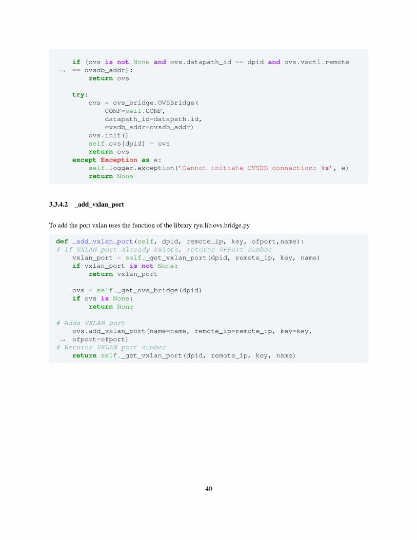
if (ovs is not None and ovs.datapath_id == dpid and ovs.vsctl.remote== ovsdb_addr):↪→
return ovs
try:ovs = ovs_bridge.OVSBridge(
CONF=self.CONF,datapath_id=datapath.id,ovsdb_addr=ovsdb_addr)
ovs.init()self.ovs[dpid] = ovsreturn ovs
except Exception as e:self.logger.exception(’Cannot initiate OVSDB connection: %s’, e)return None
3.3.4.2 _add_vxlan_port
To add the port vxlan uses the function of the library ryu.lib.ovs.bridge.py
def _add_vxlan_port(self, dpid, remote_ip, key, ofport,name):# If VXLAN port already exists, returns OFPort number
vxlan_port = self._get_vxlan_port(dpid, remote_ip, key, name)if vxlan_port is not None:
return vxlan_port
ovs = self._get_ovs_bridge(dpid)if ovs is None:
return None
# Adds VXLAN portovs.add_vxlan_port(name=name, remote_ip=remote_ip, key=key,ofport=ofport)↪→
# Returns VXLAN port numberreturn self._get_vxlan_port(dpid, remote_ip, key, name)
40
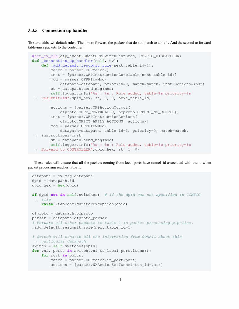
3.3.5 Connection up handler
To start, adds two default rules. The first to forward the packets that do not match to table 1. And the second to forwardtable-miss packets to the controller.
@set_ev_cls(ofp_event.EventOFPSwitchFeatures, CONFIG_DISPATCHER)def _connection_up_handler(self, ev):
def _add_default_resubmit_rule(next_table_id=1):match = parser.OFPMatch()inst = [parser.OFPInstructionGotoTable(next_table_id)]mod = parser.OFPFlowMod(
datapath=datapath, priority=0, match=match, instructions=inst)st = datapath.send_msg(mod)self.logger.info("%s : %s : Rule added, table=%s priority=%s
resubmit=%s",dpid_hex, st, 0, 0, next_table_id)↪→
actions = [parser.OFPActionOutput(ofproto.OFPP_CONTROLLER, ofproto.OFPCML_NO_BUFFER)]
inst = [parser.OFPInstructionActions(ofproto.OFPIT_APPLY_ACTIONS, actions)]
mod = parser.OFPFlowMod(datapath=datapath, table_id=1, priority=0, match=match,
instructions=inst)↪→
st = datapath.send_msg(mod)self.logger.info("%s : %s : Rule added, table=%s priority=%s
Forward to CONTROLLER",dpid_hex, st, 1, 0)↪→
These rules will ensure that all the packets coming from local ports have tunnel_id associated with them, whenpacket processing reaches table 1.
datapath = ev.msg.datapathdpid = datapath.iddpid_hex = hex(dpid)
if dpid not in self.switches: # if the dpid was not specified in CONFIGfile↪→
raise VtepConfiguratorException(dpid)
ofproto = datapath.ofprotoparser = datapath.ofproto_parser# Forward all other packets to table 1 in packet processing pipeline._add_default_resubmit_rule(next_table_id=1)
# Switch will conatin all the information from CONFIG about thisparticular datapath↪→
switch = self.switches[dpid]for vni, ports in switch.vni_to_local_port.items():
for port in ports:match = parser.OFPMatch(in_port=port)actions = [parser.NXActionSetTunnel(tun_id=vni)]
41
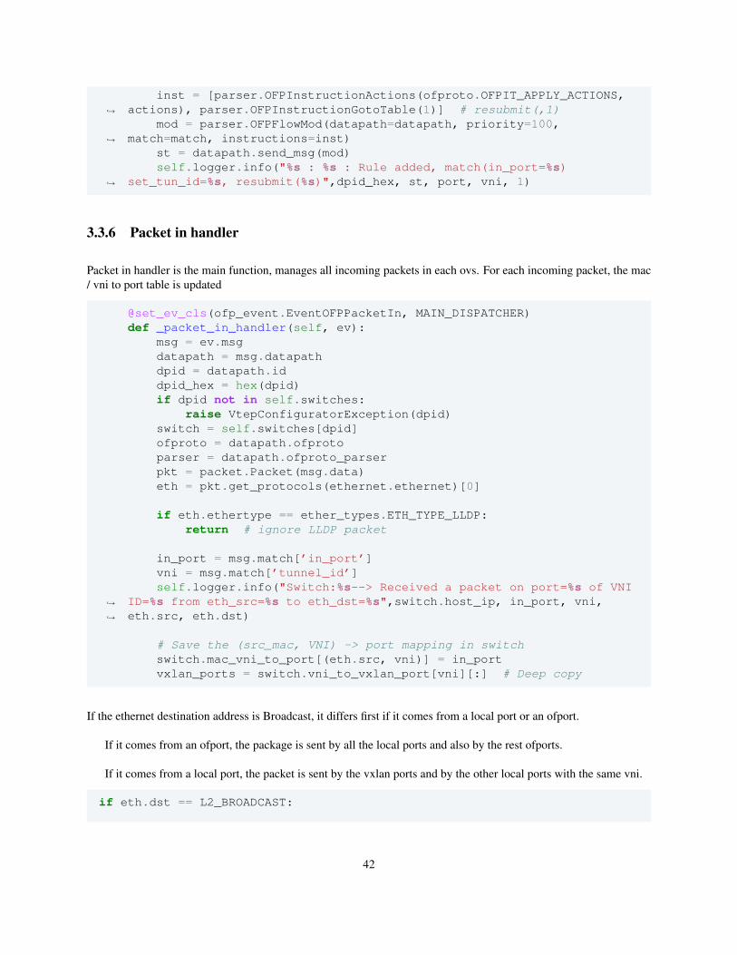
inst = [parser.OFPInstructionActions(ofproto.OFPIT_APPLY_ACTIONS,actions), parser.OFPInstructionGotoTable(1)] # resubmit(,1)↪→
mod = parser.OFPFlowMod(datapath=datapath, priority=100,match=match, instructions=inst)↪→
st = datapath.send_msg(mod)self.logger.info("%s : %s : Rule added, match(in_port=%s)
set_tun_id=%s, resubmit(%s)",dpid_hex, st, port, vni, 1)↪→
3.3.6 Packet in handler
Packet in handler is the main function, manages all incoming packets in each ovs. For each incoming packet, the mac/ vni to port table is updated
@set_ev_cls(ofp_event.EventOFPPacketIn, MAIN_DISPATCHER)def _packet_in_handler(self, ev):
msg = ev.msgdatapath = msg.datapathdpid = datapath.iddpid_hex = hex(dpid)if dpid not in self.switches:
raise VtepConfiguratorException(dpid)switch = self.switches[dpid]ofproto = datapath.ofprotoparser = datapath.ofproto_parserpkt = packet.Packet(msg.data)eth = pkt.get_protocols(ethernet.ethernet)[0]
if eth.ethertype == ether_types.ETH_TYPE_LLDP:return # ignore LLDP packet
in_port = msg.match[’in_port’]vni = msg.match[’tunnel_id’]self.logger.info("Switch:%s--> Received a packet on port=%s of VNI
ID=%s from eth_src=%s to eth_dst=%s",switch.host_ip, in_port, vni,eth.src, eth.dst)
↪→
↪→
# Save the (src_mac, VNI) -> port mapping in switchswitch.mac_vni_to_port[(eth.src, vni)] = in_portvxlan_ports = switch.vni_to_vxlan_port[vni][:] # Deep copy
If the ethernet destination address is Broadcast, it differs first if it comes from a local port or an ofport.
If it comes from an ofport, the package is sent by all the local ports and also by the rest ofports.
If it comes from a local port, the packet is sent by the vxlan ports and by the other local ports with the same vni.
if eth.dst == L2_BROADCAST:
42
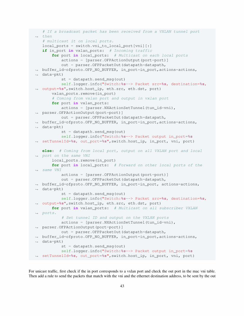
# If a broadcast packet has been received from a VXLAN tunnel portthen↪→
# multicast it on local ports.local_ports = switch.vni_to_local_port[vni][:]if in_port in vxlan_ports: # Incoming traffic
for port in local_ports: # Multicast on each local portsactions = [parser.OFPActionOutput(port=port)]out = parser.OFPPacketOut(datapath=datapath,
buffer_id=ofproto.OFP_NO_BUFFER, in_port=in_port,actions=actions,data=pkt)
↪→
↪→
st = datapath.send_msg(out)self.logger.info("Switch:%s--> Packet src=%s, destination=%s,
output=%s",switch.host_ip, eth.src, eth.dst, port)↪→
vxlan_ports.remove(in_port)# Coming from vxlan port and output in vxlan portfor port in vxlan_ports:
actions = [parser.NXActionSetTunnel(tun_id=vni),parser.OFPActionOutput(port=port)]↪→
out = parser.OFPPacketOut(datapath=datapath,buffer_id=ofproto.OFP_NO_BUFFER, in_port=in_port,actions=actions,data=pkt)
↪→
↪→
st = datapath.send_msg(out)self.logger.info("Switch:%s--> Packet output in_port=%s
setTunnelId=%s, out_port=%s",switch.host_ip, in_port, vni, port)↪→
else: # Coming from local port, output on all VXLAN port and localport on the same VNI↪→
local_ports.remove(in_port)for port in local_ports: # Forward on other local ports of the
same VNI↪→
actions = [parser.OFPActionOutput(port=port)]out = parser.OFPPacketOut(datapath=datapath,
buffer_id=ofproto.OFP_NO_BUFFER, in_port=in_port, actions=actions,data=pkt)
↪→
↪→
st = datapath.send_msg(out)self.logger.info("Switch:%s--> Packet src=%s, destination=%s,
output=%s",switch.host_ip, eth.src, eth.dst, port)↪→
for port in vxlan_ports: # Multicast on all subscriber VXLANports.↪→
# Set tunnel ID and output on the VXLAN portsactions = [parser.NXActionSetTunnel(tun_id=vni),
parser.OFPActionOutput(port=port)]↪→
out = parser.OFPPacketOut(datapath=datapath,buffer_id=ofproto.OFP_NO_BUFFER, in_port=in_port,actions=actions,data=pkt)
↪→
↪→
st = datapath.send_msg(out)self.logger.info("Switch:%s--> Packet output in_port=%s
setTunnelId=%s, out_port=%s",switch.host_ip, in_port, vni, port)↪→
For unicast traffic, first check if the in port corresponds to a vxlan port and check the out port in the mac vni table.Then add a rule to send the packets that match with the vni and the ethernet destination address, to be sent by the out
43
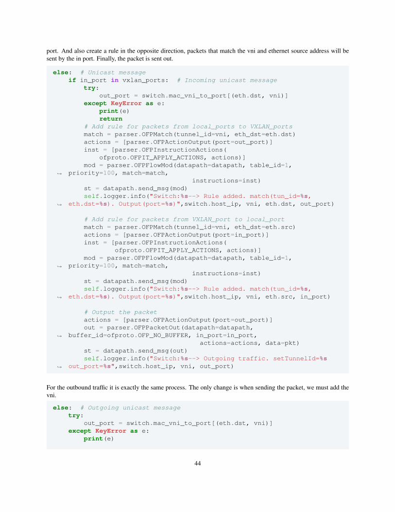
port. And also create a rule in the opposite direction, packets that match the vni and ethernet source address will besent by the in port. Finally, the packet is sent out.
else: # Unicast messageif in_port in vxlan_ports: # Incoming unicast message
try:out_port = switch.mac_vni_to_port[(eth.dst, vni)]
except KeyError as e:print(e)return
# Add rule for packets from local_ports to VXLAN_portsmatch = parser.OFPMatch(tunnel_id=vni, eth_dst=eth.dst)actions = [parser.OFPActionOutput(port=out_port)]inst = [parser.OFPInstructionActions(
ofproto.OFPIT_APPLY_ACTIONS, actions)]mod = parser.OFPFlowMod(datapath=datapath, table_id=1,
priority=100, match=match,↪→
instructions=inst)st = datapath.send_msg(mod)self.logger.info("Switch:%s--> Rule added. match(tun_id=%s,
eth.dst=%s). Output(port=%s)",switch.host_ip, vni, eth.dst, out_port)↪→
# Add rule for packets from VXLAN_port to local_portmatch = parser.OFPMatch(tunnel_id=vni, eth_dst=eth.src)actions = [parser.OFPActionOutput(port=in_port)]inst = [parser.OFPInstructionActions(
ofproto.OFPIT_APPLY_ACTIONS, actions)]mod = parser.OFPFlowMod(datapath=datapath, table_id=1,
priority=100, match=match,↪→
instructions=inst)st = datapath.send_msg(mod)self.logger.info("Switch:%s--> Rule added. match(tun_id=%s,
eth.dst=%s). Output(port=%s)",switch.host_ip, vni, eth.src, in_port)↪→
# Output the packetactions = [parser.OFPActionOutput(port=out_port)]out = parser.OFPPacketOut(datapath=datapath,
buffer_id=ofproto.OFP_NO_BUFFER, in_port=in_port,↪→
actions=actions, data=pkt)st = datapath.send_msg(out)self.logger.info("Switch:%s--> Outgoing traffic. setTunnelId=%s
out_port=%s",switch.host_ip, vni, out_port)↪→
For the outbound traffic it is exactly the same process. The only change is when sending the packet, we must add thevni.
else: # Outgoing unicast messagetry:
out_port = switch.mac_vni_to_port[(eth.dst, vni)]except KeyError as e:
print(e)
44
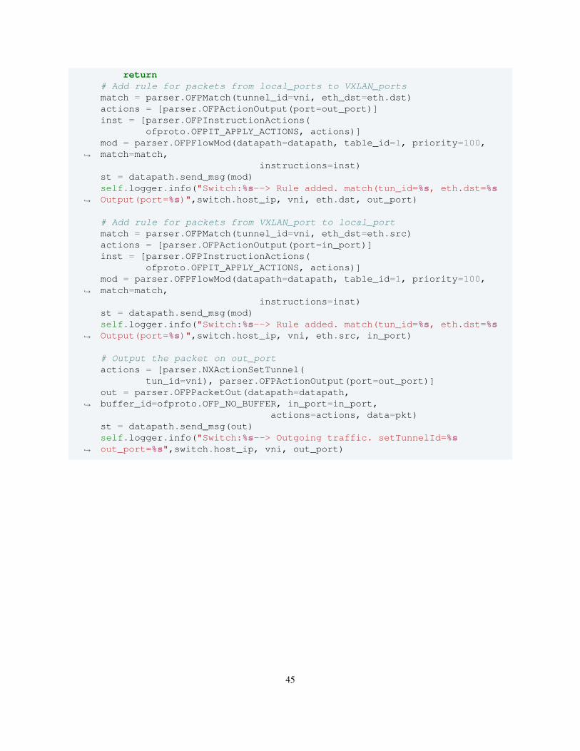
return# Add rule for packets from local_ports to VXLAN_portsmatch = parser.OFPMatch(tunnel_id=vni, eth_dst=eth.dst)actions = [parser.OFPActionOutput(port=out_port)]inst = [parser.OFPInstructionActions(
ofproto.OFPIT_APPLY_ACTIONS, actions)]mod = parser.OFPFlowMod(datapath=datapath, table_id=1, priority=100,match=match,↪→
instructions=inst)st = datapath.send_msg(mod)self.logger.info("Switch:%s--> Rule added. match(tun_id=%s, eth.dst=%sOutput(port=%s)",switch.host_ip, vni, eth.dst, out_port)↪→
# Add rule for packets from VXLAN_port to local_portmatch = parser.OFPMatch(tunnel_id=vni, eth_dst=eth.src)actions = [parser.OFPActionOutput(port=in_port)]inst = [parser.OFPInstructionActions(
ofproto.OFPIT_APPLY_ACTIONS, actions)]mod = parser.OFPFlowMod(datapath=datapath, table_id=1, priority=100,match=match,↪→
instructions=inst)st = datapath.send_msg(mod)self.logger.info("Switch:%s--> Rule added. match(tun_id=%s, eth.dst=%sOutput(port=%s)",switch.host_ip, vni, eth.src, in_port)↪→
# Output the packet on out_portactions = [parser.NXActionSetTunnel(
tun_id=vni), parser.OFPActionOutput(port=out_port)]out = parser.OFPPacketOut(datapath=datapath,buffer_id=ofproto.OFP_NO_BUFFER, in_port=in_port,↪→
actions=actions, data=pkt)st = datapath.send_msg(out)self.logger.info("Switch:%s--> Outgoing traffic. setTunnelId=%sout_port=%s",switch.host_ip, vni, out_port)↪→
45

46
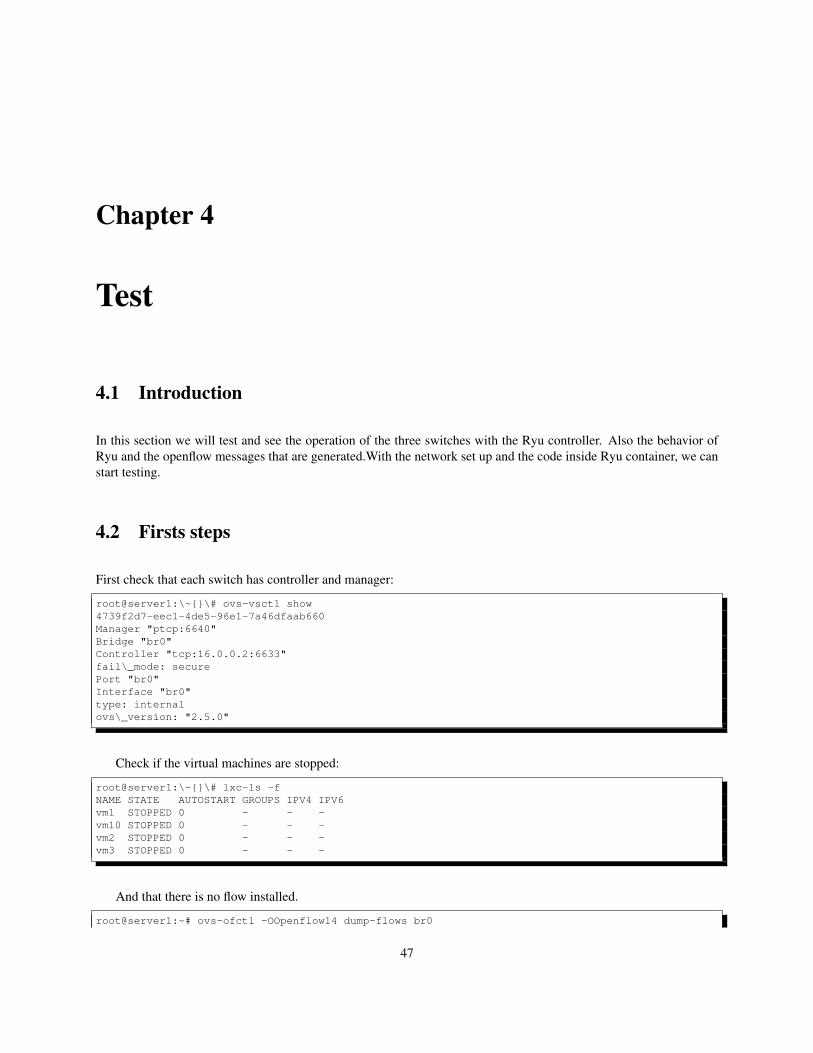
Chapter 4
Test
4.1 Introduction
In this section we will test and see the operation of the three switches with the Ryu controller. Also the behavior ofRyu and the openflow messages that are generated.With the network set up and the code inside Ryu container, we canstart testing.
4.2 Firsts steps
First check that each switch has controller and manager:
root@server1:\~{}\# ovs-vsctl show4739f2d7-eec1-4de5-96e1-7a46dfaab660Manager "ptcp:6640"Bridge "br0"Controller "tcp:16.0.0.2:6633"fail\_mode: securePort "br0"Interface "br0"type: internalovs\_version: "2.5.0"
Check if the virtual machines are stopped:
root@server1:\~{}\# lxc-ls -fNAME STATE AUTOSTART GROUPS IPV4 IPV6vm1 STOPPED 0 - - -vm10 STOPPED 0 - - -vm2 STOPPED 0 - - -vm3 STOPPED 0 - - -
And that there is no flow installed.
root@server1:~# ovs-ofctl -OOpenflow14 dump-flows br0
47
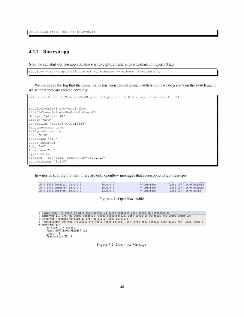
OFPST_FLOW reply (OF1.4) (xid=0x2):
4.2.1 Run ryu app
Now we can start our ryu app and also start to capture trafic with wireshark in hyperbr0 tap:
root@ryu:~/app/vtep_configurator# ryu-manager --verbose vxlan_auto.py
We can see in the log that the tunnel vxlan has been created in each switch and if we do a show on the switch againwe see that they are created correctly.
Switch:14.0.0.2--> Create VXLAN port v0(ip\_dst: 15.0.0.2 key: flow ofport: 10)
root@server1:~# ovs-vsctl show4739f2d7-eec1-4de5-96e1-7a46dfaab660Manager "ptcp:6640"Bridge "br0"Controller "tcp:16.0.0.2:6633"is_connected: truefail_mode: securePort "br0"Interface "br0"type: internalPort "v0"Interface "v0"type: vxlanoptions: {key=flow, remote_ip="15.0.0.2"}ovs_version: "2.5.0"
In wireshark, at the moment, there are only openflow messages that correspond to tcp messages.
Figure 4.1: Openflow traffic
Figure 4.2: Openflow Message
48
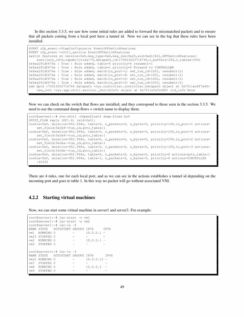
In this section 3.3.5, we saw how some initial rules are added to forward the missmatched packets and to ensurethat all packets coming from a local port have a tunnel id. Now we can see in the log that these rules have beeninstalled.
EVENT ofp_event->VtepConfigurator EventOFPSwitchFeaturesEVENT ofp_event->ofctl_service EventOFPSwitchFeaturesswitch features ev version=0x5,msg_type=0x6,msg_len=0x20,xid=0xd11821,OFPSwitchFeatures(
auxiliary_id=0,capabilities=79,datapath_id=170023022716746,n_buffers=256,n_tables=254)0x9aa291df674a : True : Rule added, table=0 priority=0 resubmit=10x9aa291df674a : True : Rule added, table=1 priority=0 Forward to CONTROLLER0x9aa291df674a : True : Rule added, match(in_port=1) set_tun_id=1001, resubmit(1)0x9aa291df674a : True : Rule added, match(in_port=4) set_tun_id=1001, resubmit(1)0x9aa291df674a : True : Rule added, match(in_port=2) set_tun_id=1002, resubmit(1)0x9aa291df674a : True : Rule added, match(in_port=3) set_tun_id=1003, resubmit(1)add dpid 170023022716746 datapath <ryu.controller.controller.Datapath object at 0x7f11ec8f7e90>
new_info <ryu.app.ofctl.service._SwitchInfo object at 0x7f11efe22d90> old_info None
Now we can check on the switch that flows are installed, and they correspond to those seen in the section 3.3.5. Weneed to use the command dump-flows + switch name to display them.
root@server1:~# ovs-ofctl -OOpenflow14 dump-flows br0OFPST_FLOW reply (OF1.4) (xid=0x2):cookie=0x0, duration=952.994s, table=0, n_packets=0, n_bytes=0, priority=100,in_port=1 actions=
set_field:0x3e9->tun_id,goto_table:1cookie=0x0, duration=952.994s, table=0, n_packets=0, n_bytes=0, priority=100,in_port=4 actions=
set_field:0x3e9->tun_id,goto_table:1cookie=0x0, duration=952.994s, table=0, n_packets=0, n_bytes=0, priority=100,in_port=2 actions=
set_field:0x3ea->tun_id,goto_table:1cookie=0x0, duration=952.994s, table=0, n_packets=0, n_bytes=0, priority=100,in_port=3 actions=
set_field:0x3eb->tun_id,goto_table:1cookie=0x0, duration=952.994s, table=0, n_packets=0, n_bytes=0, priority=0 actions=goto_table:1cookie=0x0, duration=952.994s, table=1, n_packets=0, n_bytes=0, priority=0 actions=CONTROLLER
:65535
There are 4 rules, one for each local port, and as we can see in the actions establishes a tunnel id depending on theincoming port and goes to table 1. In this way no packet will go without associated VNI.
4.2.2 Starting virtual machines
Now, we can start some virtual machine in server1 and server3. For example:
root@server1:~# lxc-start -n vm1root@server1:~# lxc-start -n vm2root@server1:~# lxc-ls -fNAME STATE AUTOSTART GROUPS IPV4 IPV6vm1 RUNNING 0 - 10.0.0.1 -vm10 STOPPED 0 - - -vm2 RUNNING 0 - 10.0.0.1 -vm3 STOPPED 0 - - -
root@server3:~# lxc-ls -fNAME STATE AUTOSTART GROUPS IPV4 IPV6vm12 RUNNING 0 - 10.0.0.13 -vm7 STOPPED 0 - - -vm8 RUNNING 0 - 10.0.0.3 -vm9 STOPPED 0 - - -
49
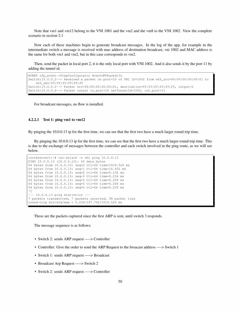
Note that vm1 and vm12 belong to the VNI 1001 and the vm2 and the vm8 to the VNI 1002. View the completescenario in section 2.1
Now each of these machines begin to generate broadcast messages. In the log of the app, for example in theintermediate switch a message is received with mac address of destination broadcast, vni 1002 and MAC address isthe same for both vm1 and vm2, but in this case corresponds to vm2.
Then, send the packet in local port 2, it is the only local port with VNI 1002. And it also sends it by the port 11 byadding the tunnel id.
EVENT ofp_event->VtepConfigurator EventOFPPacketInSwitch:15.0.0.2--> Received a packet on port=10 of VNI ID=1002 from eth_src=00:00:00:00:00:01 to
eth_dst=ff:ff:ff:ff:ff:ffSwitch:15.0.0.2--> Packet src=00:00:00:00:00:01, destination=ff:ff:ff:ff:ff:ff, output=2Switch:15.0.0.2--> Packet output in_port=10 setTunnelId=1002, out_port=11
For broadcast messages, no flow is installed.
4.2.2.1 Test 1: ping vm1 to vm12
By pinging the 10.0.0.13 ip for the first time, we can see that the first two have a much larger round trip time.
By pinging the 10.0.0.13 ip for the first time, we can see that the first two have a much larger round trip time. Thisis due to the exchange of messages between the controller and each switch involved in the ping route, as we will seebelow.
root@server1:~# lxc-attach -n vm1 ping 10.0.0.13PING 10.0.0.13 (10.0.0.13): 56 data bytes64 bytes from 10.0.0.13: seq=0 ttl=64 time=1016.524 ms64 bytes from 10.0.0.13: seq=1 ttl=64 time=16.452 ms64 bytes from 10.0.0.13: seq=2 ttl=64 time=0.236 ms64 bytes from 10.0.0.13: seq=3 ttl=64 time=0.234 ms64 bytes from 10.0.0.13: seq=4 ttl=64 time=0.249 ms64 bytes from 10.0.0.13: seq=5 ttl=64 time=0.264 ms64 bytes from 10.0.0.13: seq=6 ttl=64 time=0.239 ms^C--- 10.0.0.13 ping statistics ---7 packets transmitted, 7 packets received, 0% packet lossround-trip min/avg/max = 0.234/147.742/1016.524 ms
These are the packets captured since the first ARP is sent, until switch 3 responds.
The message sequence is as follows:
• Switch 2: sends ARP request —–> Controller
• Controller: Give the order to send the ARP Request to the broacast address —-> Switch 1
• Switch 1: sends ARP request —–> Broadcast
• Broadcast Arp Request —–> Switch 2
• Switch 2: sends ARP request —–> Controller
50
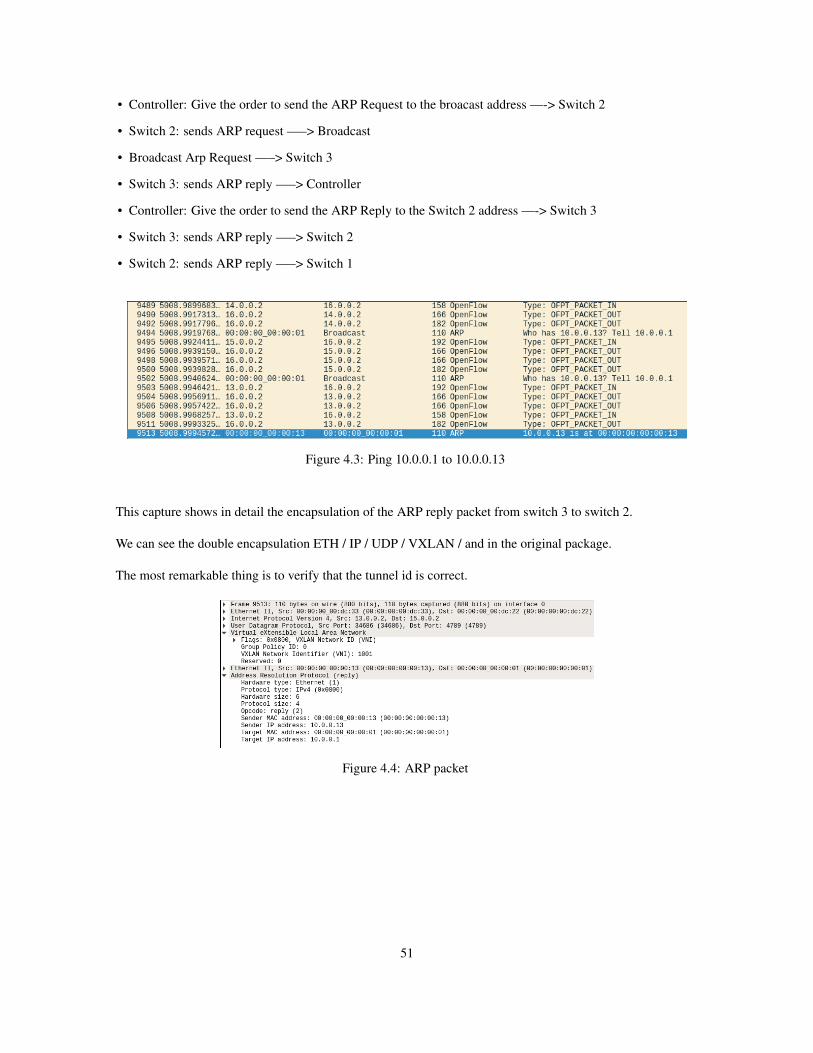
• Controller: Give the order to send the ARP Request to the broacast address —-> Switch 2
• Switch 2: sends ARP request —–> Broadcast
• Broadcast Arp Request —–> Switch 3
• Switch 3: sends ARP reply —–> Controller
• Controller: Give the order to send the ARP Reply to the Switch 2 address —-> Switch 3
• Switch 3: sends ARP reply —–> Switch 2
• Switch 2: sends ARP reply —–> Switch 1
Figure 4.3: Ping 10.0.0.1 to 10.0.0.13
This capture shows in detail the encapsulation of the ARP reply packet from switch 3 to switch 2.
We can see the double encapsulation ETH / IP / UDP / VXLAN / and in the original package.
The most remarkable thing is to verify that the tunnel id is correct.
Figure 4.4: ARP packet
51
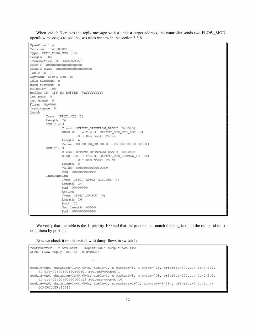
When switch 3 creates the reply message with a unicast target address, the controller sends two FLOW_MODopenflow messages to add the two rules we saw in the section 3.3.6.
OpenFlow 1.4Version: 1.4 (0x05)Type: OFPT_FLOW_MOD (14)Length: 104Transaction ID: 3485369357Cookie: 0x0000000000000000Cookie mask: 0x0000000000000000Table ID: 1Command: OFPFC_ADD (0)Idle timeout: 0Hard timeout: 0Priority: 100Buffer ID: OFP_NO_BUFFER (0xffffffff)Out port: 0Out group: 0Flags: 0x0000Importance: 0Match
Type: OFPMT_OXM (1)Length: 26OXM field
Class: OFPXMC_OPENFLOW_BASIC (0x8000)0000 011. = Field: OFPXMT_OFB_ETH_DST (3).... ...0 = Has mask: FalseLength: 6Value: 00:00:00_00:00:01 (00:00:00:00:00:01)
OXM fieldClass: OFPXMC_OPENFLOW_BASIC (0x8000)0100 110. = Field: OFPXMT_OFB_TUNNEL_ID (38).... ...0 = Has mask: FalseLength: 8Value: 00000000000003e9Pad: 000000000000
InstructionType: OFPIT_APPLY_ACTIONS (4)Length: 24Pad: 00000000ActionType: OFPAT_OUTPUT (0)Length: 16Port: 11Max length: 65509Pad: 000000000000
We verify that the table is the 1, priority 100 and that the packets that match the eth_dest and the tunnel id mustsend them by port 11.
Now we check it on the switch with dump-flows in switch 1:
root@server1:~# ovs-ofctl -OOpenflow14 dump-flows br0OFPST_FLOW reply (OF1.4) (xid=0x2):
...
cookie=0x0, duration=1240.604s, table=1, n_packets=8, n_bytes=728, priority=100,tun_id=0x3e9,dl_dst=00:00:00:00:00:01 actions=output:1
cookie=0x0, duration=1240.604s, table=1, n_packets=8, n_bytes=728, priority=100,tun_id=0x3e9,dl_dst=00:00:00:00:00:13 actions=output:10
cookie=0x0, duration=1444.606s, table=1, n_packets=1671, n_bytes=484214, priority=0 actions=CONTROLLER:65535
52
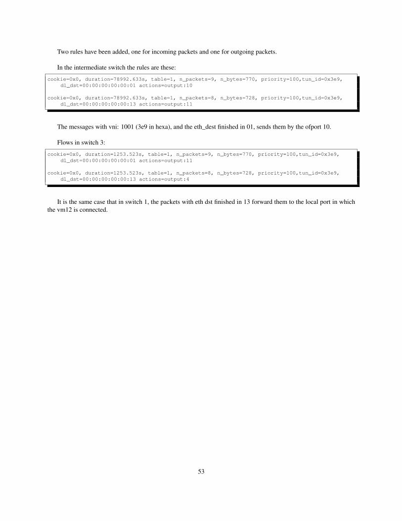
Two rules have been added, one for incoming packets and one for outgoing packets.
In the intermediate switch the rules are these:
cookie=0x0, duration=78992.633s, table=1, n_packets=9, n_bytes=770, priority=100,tun_id=0x3e9,dl_dst=00:00:00:00:00:01 actions=output:10
cookie=0x0, duration=78992.633s, table=1, n_packets=8, n_bytes=728, priority=100,tun_id=0x3e9,dl_dst=00:00:00:00:00:13 actions=output:11
The messages with vni: 1001 (3e9 in hexa), and the eth_dest finished in 01, sends them by the ofport 10.
Flows in switch 3:
cookie=0x0, duration=1253.523s, table=1, n_packets=9, n_bytes=770, priority=100,tun_id=0x3e9,dl_dst=00:00:00:00:00:01 actions=output:11
cookie=0x0, duration=1253.523s, table=1, n_packets=8, n_bytes=728, priority=100,tun_id=0x3e9,dl_dst=00:00:00:00:00:13 actions=output:4
It is the same case that in switch 1, the packets with eth dst finished in 13 forward them to the local port in whichthe vm12 is connected.
53

54
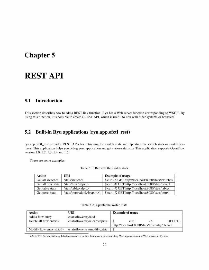
Chapter 5
REST API
5.1 Introduction
This section describes how to add a REST link function. Ryu has a Web server function corresponding to WSGI1. Byusing this function, it is possible to create a REST API, which is useful to link with other systems or browsers.
5.2 Built-in Ryu applications (ryu.app.ofctl_rest)
ryu.app.ofctl_rest provides REST APIs for retrieving the switch stats and Updating the switch stats or switch fea-tures. This application helps you debug your application and get various statistics.This application supports OpenFlowversion 1.0, 1.2, 1.3, 1.4 and 1.5.
These are some examples:
Table 5.1: Retrieve the switch stats
Action URI Example of usageGet all switches /stats/switches $ curl -X GET http://localhost:8080/stats/switchesGet all flow stats /stats/flow/<dpid> $ curl -X GET http://localhost:8080/stats/flow/1Get table stats /stats/table/<dpid> $ curl -X GET http://localhost:8080/stats/table/1Get ports stats /stats/port/<dpid>[/<port>] $ curl -X GET http://localhost:8080/stats/port/1
Table 5.2: Update the switch stats
Action URI Example of usageAdd a flow entry /stats/flowentry/addDelete all flow entries /stats/flowentry/clear/<dpid> $ curl -X DELETE
http://localhost:8080/stats/flowentry/clear/1Modify flow entry strictly /stats/flowentry/modify_strict $
1WSGI(Web Server Gateway Interface) means a unified framework for connecting Web applications and Web servers in Python.
55
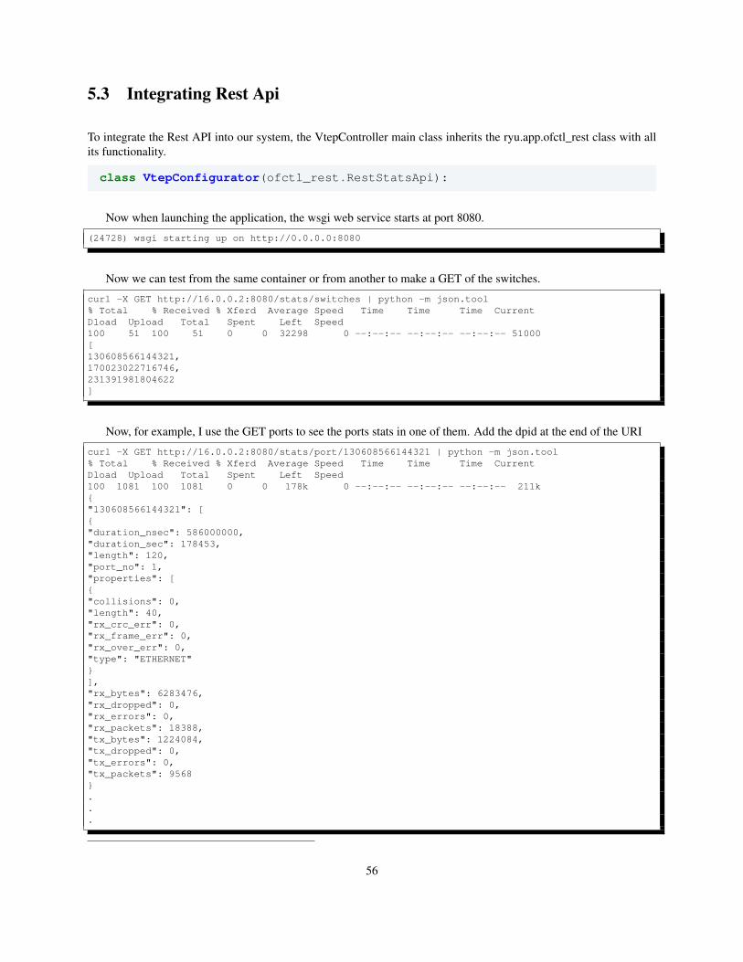
5.3 Integrating Rest Api
To integrate the Rest API into our system, the VtepController main class inherits the ryu.app.ofctl_rest class with allits functionality.
class VtepConfigurator(ofctl_rest.RestStatsApi):
Now when launching the application, the wsgi web service starts at port 8080.
(24728) wsgi starting up on http://0.0.0.0:8080
Now we can test from the same container or from another to make a GET of the switches.
curl -X GET http://16.0.0.2:8080/stats/switches | python -m json.tool% Total % Received % Xferd Average Speed Time Time Time CurrentDload Upload Total Spent Left Speed100 51 100 51 0 0 32298 0 --:--:-- --:--:-- --:--:-- 51000[130608566144321,170023022716746,231391981804622]
Now, for example, I use the GET ports to see the ports stats in one of them. Add the dpid at the end of the URI
curl -X GET http://16.0.0.2:8080/stats/port/130608566144321 | python -m json.tool% Total % Received % Xferd Average Speed Time Time Time CurrentDload Upload Total Spent Left Speed100 1081 100 1081 0 0 178k 0 --:--:-- --:--:-- --:--:-- 211k{"130608566144321": [{"duration_nsec": 586000000,"duration_sec": 178453,"length": 120,"port_no": 1,"properties": [{"collisions": 0,"length": 40,"rx_crc_err": 0,"rx_frame_err": 0,"rx_over_err": 0,"type": "ETHERNET"}],"rx_bytes": 6283476,"rx_dropped": 0,"rx_errors": 0,"rx_packets": 18388,"tx_bytes": 1224084,"tx_dropped": 0,"tx_errors": 0,"tx_packets": 9568}...
56
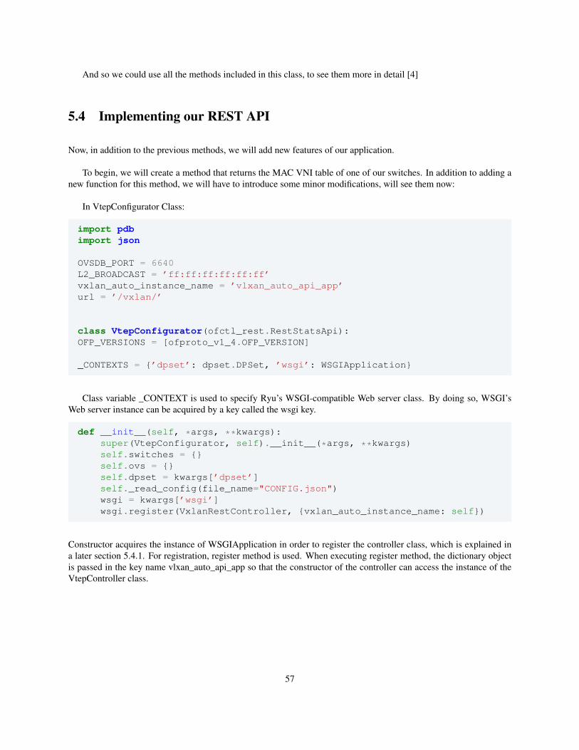
And so we could use all the methods included in this class, to see them more in detail [4]
5.4 Implementing our REST API
Now, in addition to the previous methods, we will add new features of our application.
To begin, we will create a method that returns the MAC VNI table of one of our switches. In addition to adding anew function for this method, we will have to introduce some minor modifications, will see them now:
In VtepConfigurator Class:
import pdbimport json
OVSDB_PORT = 6640L2_BROADCAST = ’ff:ff:ff:ff:ff:ff’vxlan_auto_instance_name = ’vlxan_auto_api_app’url = ’/vxlan/’
class VtepConfigurator(ofctl_rest.RestStatsApi):OFP_VERSIONS = [ofproto_v1_4.OFP_VERSION]
_CONTEXTS = {’dpset’: dpset.DPSet, ’wsgi’: WSGIApplication}
Class variable _CONTEXT is used to specify Ryu’s WSGI-compatible Web server class. By doing so, WSGI’sWeb server instance can be acquired by a key called the wsgi key.
def __init__(self, *args, **kwargs):super(VtepConfigurator, self).__init__(*args, **kwargs)self.switches = {}self.ovs = {}self.dpset = kwargs[’dpset’]self._read_config(file_name="CONFIG.json")wsgi = kwargs[’wsgi’]wsgi.register(VxlanRestController, {vxlan_auto_instance_name: self})
Constructor acquires the instance of WSGIApplication in order to register the controller class, which is explained ina later section 5.4.1. For registration, register method is used. When executing register method, the dictionary objectis passed in the key name vlxan_auto_api_app so that the constructor of the controller can access the instance of theVtepController class.
57
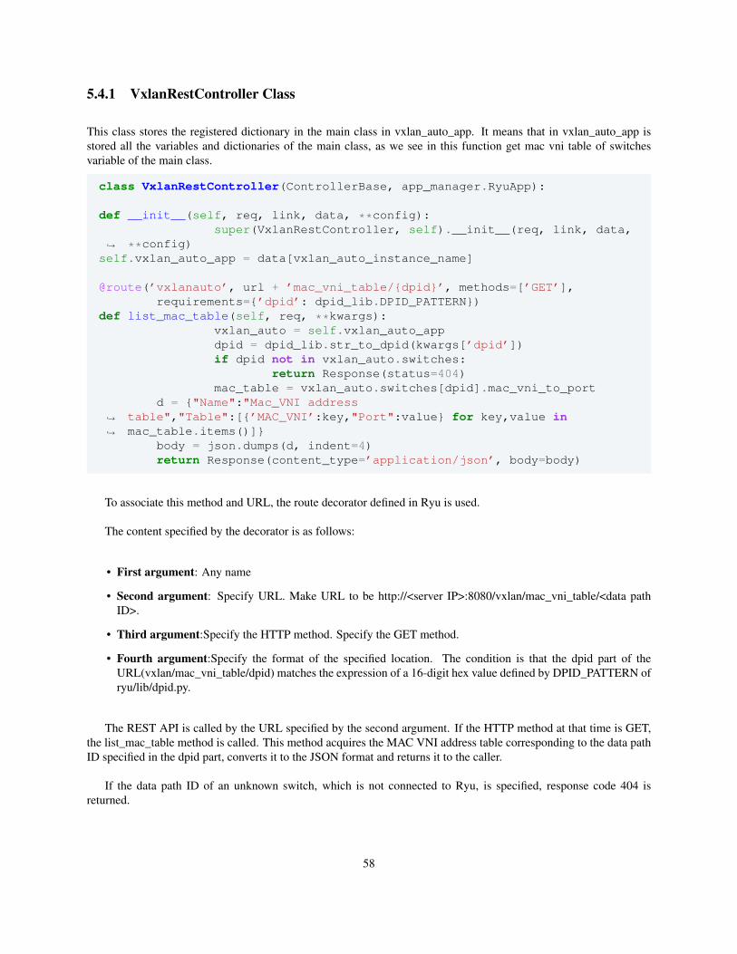
5.4.1 VxlanRestController Class
This class stores the registered dictionary in the main class in vxlan_auto_app. It means that in vxlan_auto_app isstored all the variables and dictionaries of the main class, as we see in this function get mac vni table of switchesvariable of the main class.
class VxlanRestController(ControllerBase, app_manager.RyuApp):
def __init__(self, req, link, data, **config):super(VxlanRestController, self).__init__(req, link, data,
**config)↪→
self.vxlan_auto_app = data[vxlan_auto_instance_name]
@route(’vxlanauto’, url + ’mac_vni_table/{dpid}’, methods=[’GET’],requirements={’dpid’: dpid_lib.DPID_PATTERN})
def list_mac_table(self, req, **kwargs):vxlan_auto = self.vxlan_auto_appdpid = dpid_lib.str_to_dpid(kwargs[’dpid’])if dpid not in vxlan_auto.switches:
return Response(status=404)mac_table = vxlan_auto.switches[dpid].mac_vni_to_port
d = {"Name":"Mac_VNI addresstable","Table":[{’MAC_VNI’:key,"Port":value} for key,value inmac_table.items()]}
↪→
↪→
body = json.dumps(d, indent=4)return Response(content_type=’application/json’, body=body)
To associate this method and URL, the route decorator defined in Ryu is used.
The content specified by the decorator is as follows:
• First argument: Any name
• Second argument: Specify URL. Make URL to be http://<server IP>:8080/vxlan/mac_vni_table/<data pathID>.
• Third argument:Specify the HTTP method. Specify the GET method.
• Fourth argument:Specify the format of the specified location. The condition is that the dpid part of theURL(vxlan/mac_vni_table/dpid) matches the expression of a 16-digit hex value defined by DPID_PATTERN ofryu/lib/dpid.py.
The REST API is called by the URL specified by the second argument. If the HTTP method at that time is GET,the list_mac_table method is called. This method acquires the MAC VNI address table corresponding to the data pathID specified in the dpid part, converts it to the JSON format and returns it to the caller.
If the data path ID of an unknown switch, which is not connected to Ryu, is specified, response code 404 isreturned.
58
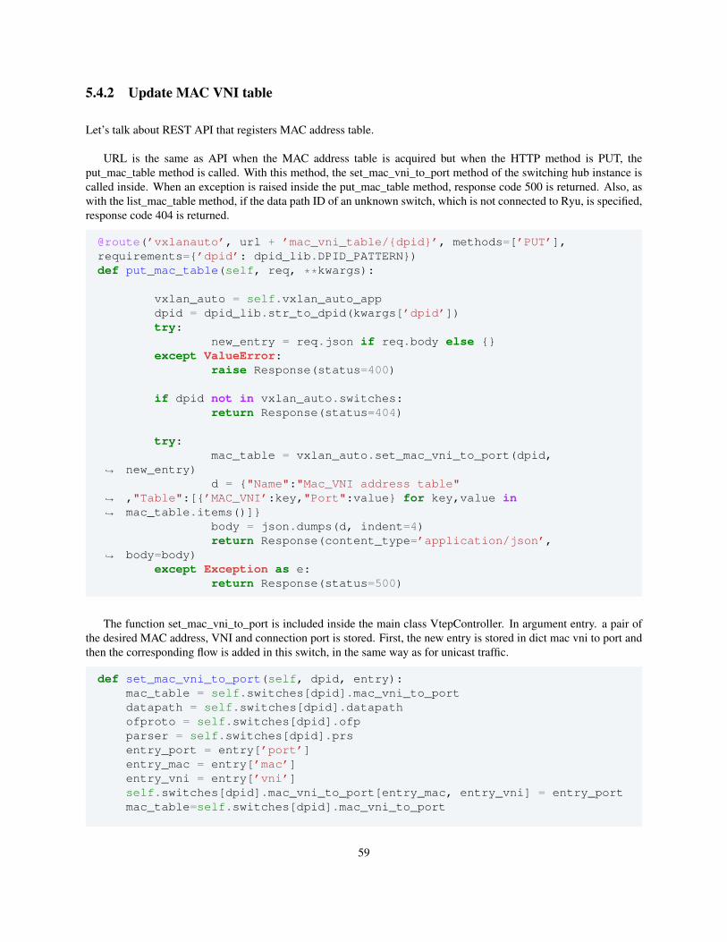
5.4.2 Update MAC VNI table
Let’s talk about REST API that registers MAC address table.
URL is the same as API when the MAC address table is acquired but when the HTTP method is PUT, theput_mac_table method is called. With this method, the set_mac_vni_to_port method of the switching hub instance iscalled inside. When an exception is raised inside the put_mac_table method, response code 500 is returned. Also, aswith the list_mac_table method, if the data path ID of an unknown switch, which is not connected to Ryu, is specified,response code 404 is returned.
@route(’vxlanauto’, url + ’mac_vni_table/{dpid}’, methods=[’PUT’],requirements={’dpid’: dpid_lib.DPID_PATTERN})def put_mac_table(self, req, **kwargs):
vxlan_auto = self.vxlan_auto_appdpid = dpid_lib.str_to_dpid(kwargs[’dpid’])try:
new_entry = req.json if req.body else {}except ValueError:
raise Response(status=400)
if dpid not in vxlan_auto.switches:return Response(status=404)
try:mac_table = vxlan_auto.set_mac_vni_to_port(dpid,
new_entry)↪→
d = {"Name":"Mac_VNI address table","Table":[{’MAC_VNI’:key,"Port":value} for key,value inmac_table.items()]}
↪→
↪→
body = json.dumps(d, indent=4)return Response(content_type=’application/json’,
body=body)↪→
except Exception as e:return Response(status=500)
The function set_mac_vni_to_port is included inside the main class VtepController. In argument entry. a pair ofthe desired MAC address, VNI and connection port is stored. First, the new entry is stored in dict mac vni to port andthen the corresponding flow is added in this switch, in the same way as for unicast traffic.
def set_mac_vni_to_port(self, dpid, entry):mac_table = self.switches[dpid].mac_vni_to_portdatapath = self.switches[dpid].datapathofproto = self.switches[dpid].ofpparser = self.switches[dpid].prsentry_port = entry[’port’]entry_mac = entry[’mac’]entry_vni = entry[’vni’]self.switches[dpid].mac_vni_to_port[entry_mac, entry_vni] = entry_portmac_table=self.switches[dpid].mac_vni_to_port
59
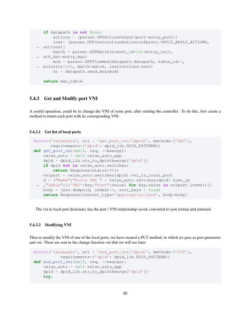
if datapath is not None:actions = [parser.OFPActionOutput(port=entry_port)]inst= [parser.OFPInstructionActions(ofproto.OFPIT_APPLY_ACTIONS,
actions)]↪→
match = parser.OFPMatch(tunnel_id=int(entry_vni),eth_dst=entry_mac)↪→
mod = parser.OFPFlowMod(datapath=datapath, table_id=1,priority=100, match=match, instructions=inst)↪→
st = datapath.send_msg(mod)
return mac_table
5.4.3 Get and Modify port VNI
A useful operation, could be to change the VNI of some port, after starting the controller. To do this, first create amethod to return each port with its corresponding VNI.
5.4.3.1 Get list of local ports
@route(’vxlanauto’, url + ’get_port_vni/{dpid}’, methods=[’GET’],requirements={’dpid’: dpid_lib.DPID_PATTERN})
def get_port_vni(self, req, **kwargs):vxlan_auto = self.vxlan_auto_appdpid = dpid_lib.str_to_dpid(kwargs[’dpid’])if dpid not in vxlan_auto.switches:
return Response(status=404)vniport = vxlan_auto.switches[dpid].vni_to_local_portd = {"Name":"Ports VNI " + vxlan_auto.switches[dpid].host_ip,"Table":[{’VNI’:key,"Port":value} for key,value in vniport.items()]}↪→
body = json.dumps(d, indent=4, sort_keys = True)return Response(content_type=’application/json’, body=body)
The vni to local port dictionary has the port / VNI relationship saved, converted to json format and returned.
5.4.3.2 Modifying VNI
Then to modify the VNI of one of the local ports, we have created a PUT method, in which we pass as port parameterand vni. These are sent to the change function vni that we will see later.
@route(’vxlanauto’, url + ’mod_port_vni/{dpid}’, methods=[’PUT’],requirements={’dpid’: dpid_lib.DPID_PATTERN})
def mod_port_vni(self, req, **kwargs):vxlan_auto = self.vxlan_auto_appdpid = dpid_lib.str_to_dpid(kwargs[’dpid’])try:
60
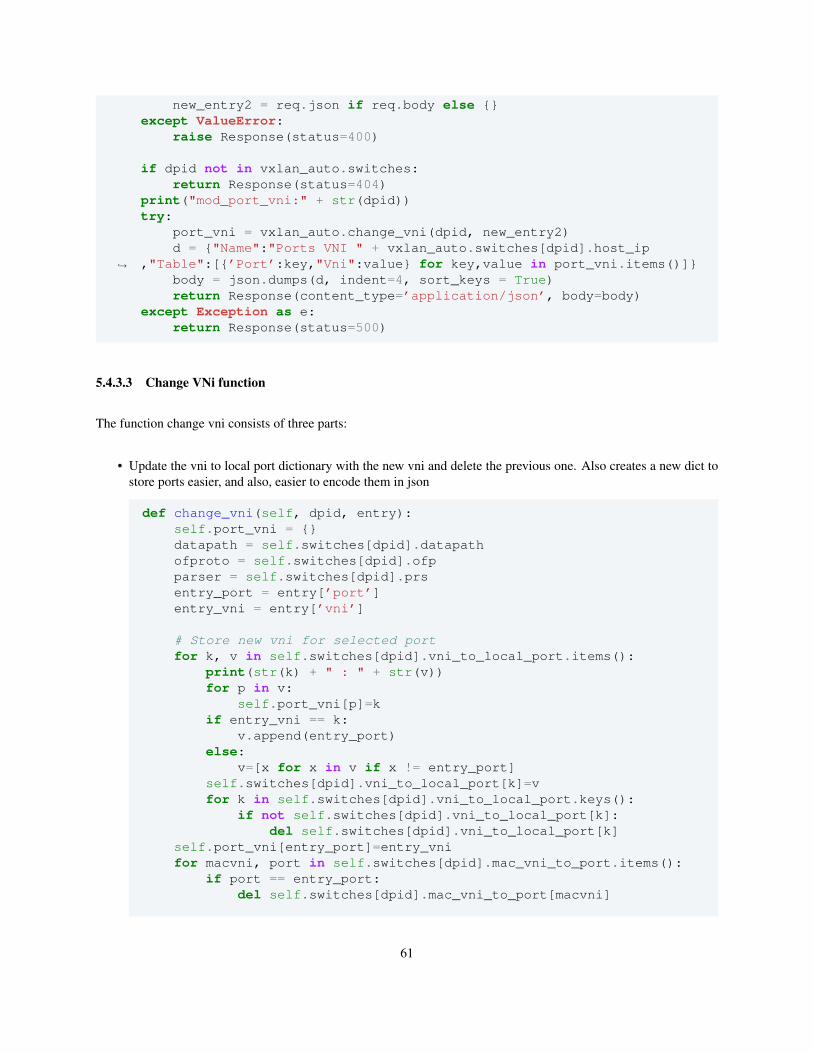
new_entry2 = req.json if req.body else {}except ValueError:
raise Response(status=400)
if dpid not in vxlan_auto.switches:return Response(status=404)
print("mod_port_vni:" + str(dpid))try:
port_vni = vxlan_auto.change_vni(dpid, new_entry2)d = {"Name":"Ports VNI " + vxlan_auto.switches[dpid].host_ip
,"Table":[{’Port’:key,"Vni":value} for key,value in port_vni.items()]}↪→
body = json.dumps(d, indent=4, sort_keys = True)return Response(content_type=’application/json’, body=body)
except Exception as e:return Response(status=500)
5.4.3.3 Change VNi function
The function change vni consists of three parts:
• Update the vni to local port dictionary with the new vni and delete the previous one. Also creates a new dict tostore ports easier, and also, easier to encode them in json
def change_vni(self, dpid, entry):self.port_vni = {}datapath = self.switches[dpid].datapathofproto = self.switches[dpid].ofpparser = self.switches[dpid].prsentry_port = entry[’port’]entry_vni = entry[’vni’]
# Store new vni for selected portfor k, v in self.switches[dpid].vni_to_local_port.items():
print(str(k) + " : " + str(v))for p in v:
self.port_vni[p]=kif entry_vni == k:
v.append(entry_port)else:
v=[x for x in v if x != entry_port]self.switches[dpid].vni_to_local_port[k]=vfor k in self.switches[dpid].vni_to_local_port.keys():
if not self.switches[dpid].vni_to_local_port[k]:del self.switches[dpid].vni_to_local_port[k]
self.port_vni[entry_port]=entry_vnifor macvni, port in self.switches[dpid].mac_vni_to_port.items():
if port == entry_port:del self.switches[dpid].mac_vni_to_port[macvni]
61
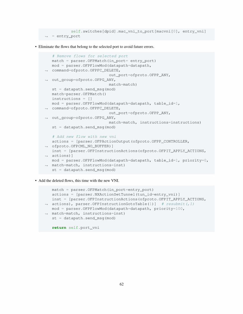
self.switches[dpid].mac_vni_to_port[macvni[0], entry_vni]= entry_port↪→
• Eliminate the flows that belong to the selected port to avoid future errors.
# Remove flows for selected portmatch = parser.OFPMatch(in_port= entry_port)mod = parser.OFPFlowMod(datapath=datapath,command=ofproto.OFPFC_DELETE,↪→
out_port=ofproto.OFPP_ANY,out_group=ofproto.OFPG_ANY,↪→
match=match)st = datapath.send_msg(mod)match=parser.OFPMatch()instructions = []mod = parser.OFPFlowMod(datapath=datapath, table_id=1,command=ofproto.OFPFC_DELETE,↪→
out_port=ofproto.OFPP_ANY,out_group=ofproto.OFPG_ANY,↪→
match=match, instructions=instructions)st = datapath.send_msg(mod)
# Add new flow with new vniactions = [parser.OFPActionOutput(ofproto.OFPP_CONTROLLER,ofproto.OFPCML_NO_BUFFER)]↪→
inst = [parser.OFPInstructionActions(ofproto.OFPIT_APPLY_ACTIONS,actions)]↪→
mod = parser.OFPFlowMod(datapath=datapath, table_id=1, priority=0,match=match, instructions=inst)↪→
st = datapath.send_msg(mod)
• Add the deleted flows, this time with the new VNI.
match = parser.OFPMatch(in_port=entry_port)actions = [parser.NXActionSetTunnel(tun_id=entry_vni)]inst = [parser.OFPInstructionActions(ofproto.OFPIT_APPLY_ACTIONS,actions), parser.OFPInstructionGotoTable(1)] # resubmit(,1)↪→
mod = parser.OFPFlowMod(datapath=datapath, priority=100,match=match, instructions=inst)↪→
st = datapath.send_msg(mod)
return self.port_vni
62
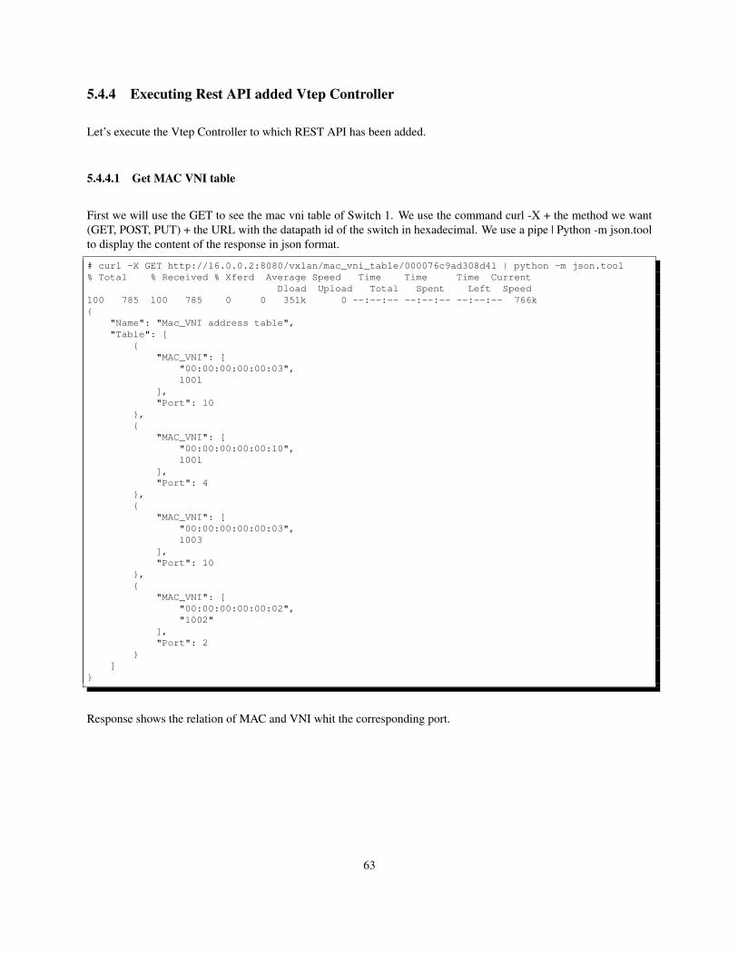
5.4.4 Executing Rest API added Vtep Controller
Let’s execute the Vtep Controller to which REST API has been added.
5.4.4.1 Get MAC VNI table
First we will use the GET to see the mac vni table of Switch 1. We use the command curl -X + the method we want(GET, POST, PUT) + the URL with the datapath id of the switch in hexadecimal. We use a pipe | Python -m json.toolto display the content of the response in json format.
# curl -X GET http://16.0.0.2:8080/vxlan/mac_vni_table/000076c9ad308d41 | python -m json.tool% Total % Received % Xferd Average Speed Time Time Time Current
Dload Upload Total Spent Left Speed100 785 100 785 0 0 351k 0 --:--:-- --:--:-- --:--:-- 766k{
"Name": "Mac_VNI address table","Table": [
{"MAC_VNI": [
"00:00:00:00:00:03",1001
],"Port": 10
},{
"MAC_VNI": ["00:00:00:00:00:10",1001
],"Port": 4
},{
"MAC_VNI": ["00:00:00:00:00:03",1003
],"Port": 10
},{
"MAC_VNI": ["00:00:00:00:00:02","1002"
],"Port": 2
}]
}
Response shows the relation of MAC and VNI whit the corresponding port.
63
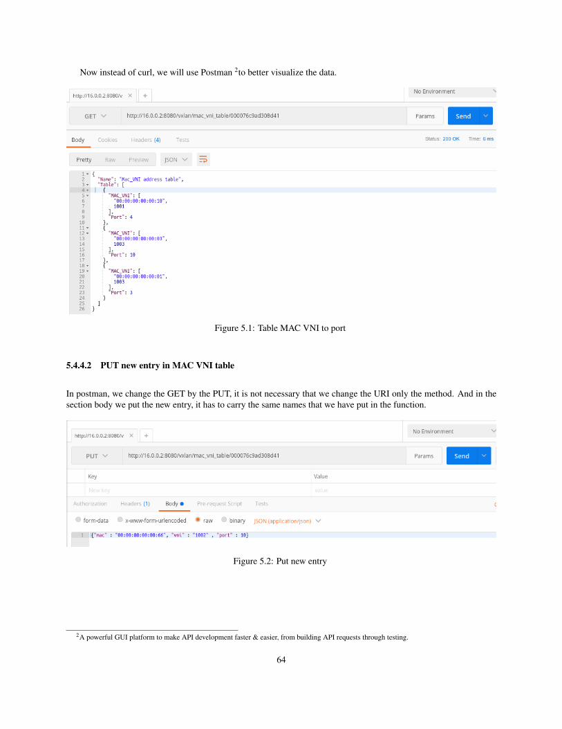
Now instead of curl, we will use Postman 2to better visualize the data.
Figure 5.1: Table MAC VNI to port
5.4.4.2 PUT new entry in MAC VNI table
In postman, we change the GET by the PUT, it is not necessary that we change the URI only the method. And in thesection body we put the new entry, it has to carry the same names that we have put in the function.
Figure 5.2: Put new entry
2A powerful GUI platform to make API development faster & easier, from building API requests through testing.
64
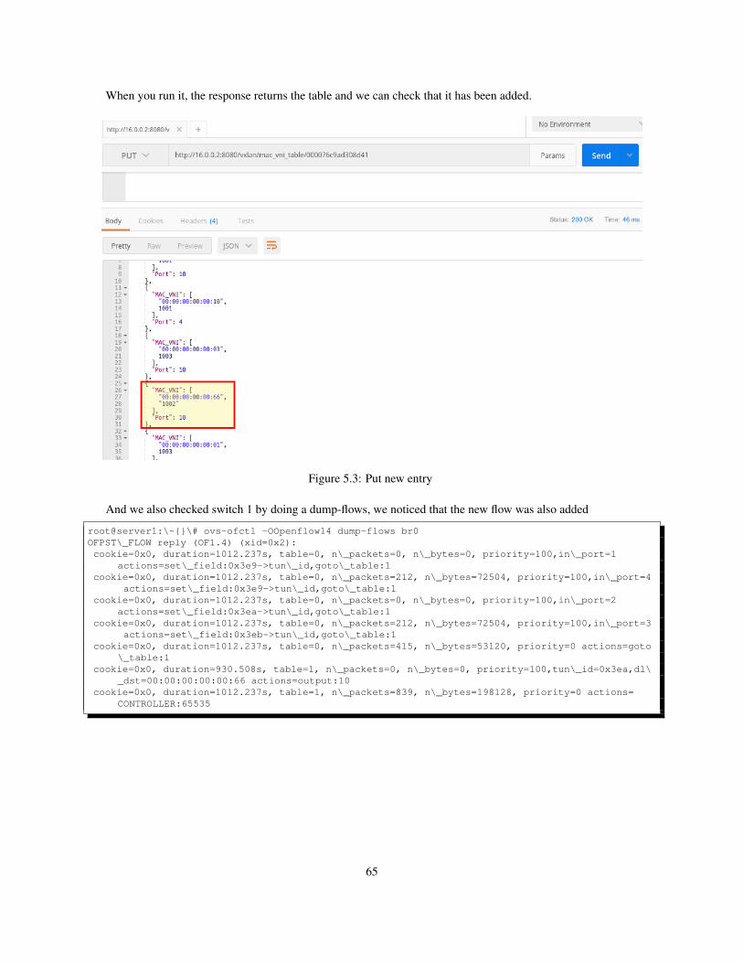
When you run it, the response returns the table and we can check that it has been added.
Figure 5.3: Put new entry
And we also checked switch 1 by doing a dump-flows, we noticed that the new flow was also added
root@server1:\~{}\# ovs-ofctl -OOpenflow14 dump-flows br0OFPST\_FLOW reply (OF1.4) (xid=0x2):cookie=0x0, duration=1012.237s, table=0, n\_packets=0, n\_bytes=0, priority=100,in\_port=1
actions=set\_field:0x3e9->tun\_id,goto\_table:1cookie=0x0, duration=1012.237s, table=0, n\_packets=212, n\_bytes=72504, priority=100,in\_port=4
actions=set\_field:0x3e9->tun\_id,goto\_table:1cookie=0x0, duration=1012.237s, table=0, n\_packets=0, n\_bytes=0, priority=100,in\_port=2
actions=set\_field:0x3ea->tun\_id,goto\_table:1cookie=0x0, duration=1012.237s, table=0, n\_packets=212, n\_bytes=72504, priority=100,in\_port=3
actions=set\_field:0x3eb->tun\_id,goto\_table:1cookie=0x0, duration=1012.237s, table=0, n\_packets=415, n\_bytes=53120, priority=0 actions=goto
\_table:1cookie=0x0, duration=930.508s, table=1, n\_packets=0, n\_bytes=0, priority=100,tun\_id=0x3ea,dl\
_dst=00:00:00:00:00:66 actions=output:10cookie=0x0, duration=1012.237s, table=1, n\_packets=839, n\_bytes=198128, priority=0 actions=
CONTROLLER:65535
65
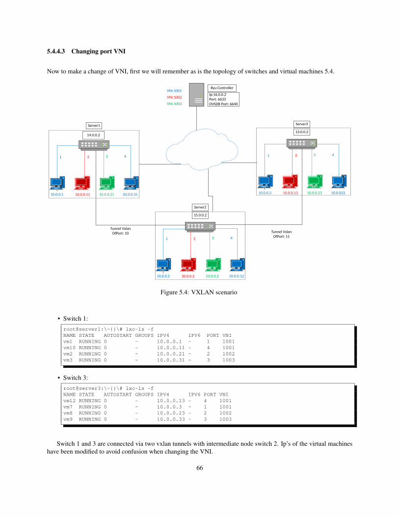
5.4.4.3 Changing port VNI
Now to make a change of VNI, first we will remember as is the topology of switches and virtual machines 5.4.
10.0.0.2 10.0.0.2 10.0.0.2 10.0.0.12
15.0.0.2
Server2
1 2 43
10.0.0.3 10.0.0.13 10.0.0.23 10.0.033
13.0.0.2
Server3
1 2 43
10.0.0.1 10.0.0.11 10.0.0.21 10.0.0.31
14.0.0.2
Server1
1 2 43
Ip:16.0.0.2Port: 6633OVSDB Port: 6640
Ryu ControllerVNI:1001
VNI:1002
VNI:1003
Tunnel VxlanOfPort: 10 Tunnel Vxlan
OfPort: 11
Figure 5.4: VXLAN scenario
• Switch 1:
root@server1:\~{}\# lxc-ls -fNAME STATE AUTOSTART GROUPS IPV4 IPV6 PORT VNIvm1 RUNNING 0 - 10.0.0.1 - 1 1001vm10 RUNNING 0 - 10.0.0.11 - 4 1001vm2 RUNNING 0 - 10.0.0.21 - 2 1002vm3 RUNNING 0 - 10.0.0.31 - 3 1003
• Switch 3:
root@server3:\~{}\# lxc-ls -fNAME STATE AUTOSTART GROUPS IPV4 IPV6 PORT VNIvm12 RUNNING 0 - 10.0.0.13 - 4 1001vm7 RUNNING 0 - 10.0.0.3 - 1 1001vm8 RUNNING 0 - 10.0.0.23 - 2 1002vm9 RUNNING 0 - 10.0.0.33 - 3 1003
Switch 1 and 3 are connected via two vxlan tunnels with intermediate node switch 2. Ip’s of the virtual machineshave been modified to avoid confusion when changing the VNI.
66
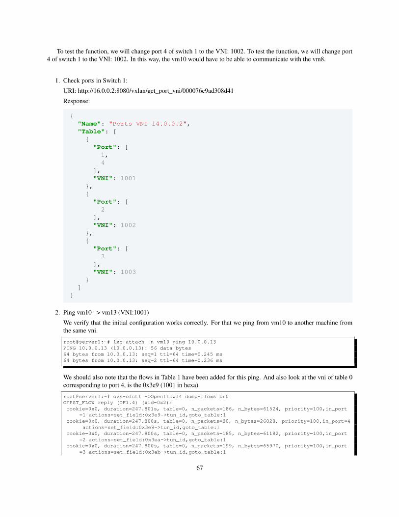
To test the function, we will change port 4 of switch 1 to the VNI: 1002. To test the function, we will change port4 of switch 1 to the VNI: 1002. In this way, the vm10 would have to be able to communicate with the vm8.
1. Check ports in Switch 1:
URI: http://16.0.0.2:8080/vxlan/get_port_vni/000076c9ad308d41
Response:
{"Name": "Ports VNI 14.0.0.2","Table": [
{"Port": [
1,4
],"VNI": 1001
},{
"Port": [2
],"VNI": 1002
},{
"Port": [3
],"VNI": 1003
}]
}
2. Ping vm10 –> vm13 (VNI:1001)
We verify that the initial configuration works correctly. For that we ping from vm10 to another machine fromthe same vni.
root@server1:~# lxc-attach -n vm10 ping 10.0.0.13PING 10.0.0.13 (10.0.0.13): 56 data bytes64 bytes from 10.0.0.13: seq=1 ttl=64 time=0.245 ms64 bytes from 10.0.0.13: seq=2 ttl=64 time=0.236 ms
We should also note that the flows in Table 1 have been added for this ping. And also look at the vni of table 0corresponding to port 4, is the 0x3e9 (1001 in hexa)
root@server1:~# ovs-ofctl -OOpenflow14 dump-flows br0OFPST_FLOW reply (OF1.4) (xid=0x2):cookie=0x0, duration=247.801s, table=0, n_packets=186, n_bytes=61524, priority=100,in_port
=1 actions=set_field:0x3e9->tun_id,goto_table:1cookie=0x0, duration=247.800s, table=0, n_packets=80, n_bytes=26028, priority=100,in_port=4
actions=set_field:0x3e9->tun_id,goto_table:1cookie=0x0, duration=247.800s, table=0, n_packets=185, n_bytes=61182, priority=100,in_port
=2 actions=set_field:0x3ea->tun_id,goto_table:1cookie=0x0, duration=247.800s, table=0, n_packets=199, n_bytes=65970, priority=100,in_port
=3 actions=set_field:0x3eb->tun_id,goto_table:1
67
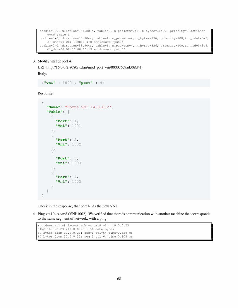
cookie=0x0, duration=247.801s, table=0, n_packets=248, n_bytes=31500, priority=0 actions=goto_table:1
cookie=0x0, duration=58.904s, table=1, n_packets=4, n_bytes=336, priority=100,tun_id=0x3e9,dl_dst=00:00:00:00:00:10 actions=output:4
cookie=0x0, duration=58.904s, table=1, n_packets=4, n_bytes=336, priority=100,tun_id=0x3e9,dl_dst=00:00:00:00:00:13 actions=output:10
3. Modify vni for port 4
URI: http://16.0.0.2:8080/vxlan/mod_port_vni/000076c9ad308d41
Body:
{"vni" : 1002 , "port" : 4}
Response:
{"Name": "Ports VNI 14.0.0.2","Table": [
{"Port": 1,"Vni": 1001
},{
"Port": 2,"Vni": 1002
},{
"Port": 3,"Vni": 1003
},{
"Port": 4,"Vni": 1002
}]
}
Check in the response, that port 4 has the new VNI.
4. Ping vm10 –> vm8 (VNI:1002). We verified that there is communication with another machine that correspondsto the same segment of network, with a ping.
root@server1:~# lxc-attach -n vm10 ping 10.0.0.23PING 10.0.0.23 (10.0.0.23): 56 data bytes64 bytes from 10.0.0.23: seq=1 ttl=64 time=0.820 ms64 bytes from 10.0.0.23: seq=2 ttl=64 time=0.205 ms
68
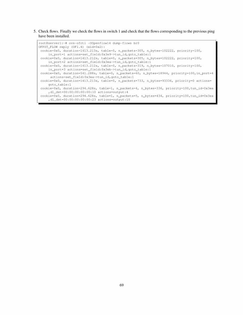
5. Check flows. Finally we check the flows in switch 1 and check that the flows corresponding to the previous pinghave been installed.
root@server1:~# ovs-ofctl -OOpenflow14 dump-flows br0OFPST_FLOW reply (OF1.4) (xid=0x2):cookie=0x0, duration=1413.213s, table=0, n_packets=305, n_bytes=102222, priority=100,
in_port=1 actions=set_field:0x3e9->tun_id,goto_table:1cookie=0x0, duration=1413.212s, table=0, n_packets=305, n_bytes=102222, priority=100,
in_port=2 actions=set_field:0x3ea->tun_id,goto_table:1cookie=0x0, duration=1413.212s, table=0, n_packets=319, n_bytes=107010, priority=100,
in_port=3 actions=set_field:0x3eb->tun_id,goto_table:1cookie=0x0, duration=541.288s, table=0, n_packets=60, n_bytes=18944, priority=100,in_port=4
actions=set_field:0x3ea->tun_id,goto_table:1cookie=0x0, duration=1413.213s, table=0, n_packets=733, n_bytes=93336, priority=0 actions=
goto_table:1cookie=0x0, duration=294.628s, table=1, n_packets=4, n_bytes=336, priority=100,tun_id=0x3ea
,dl_dst=00:00:00:00:00:10 actions=output:4cookie=0x0, duration=294.628s, table=1, n_packets=5, n_bytes=434, priority=100,tun_id=0x3ea
,dl_dst=00:00:00:00:00:23 actions=output:10
69

70
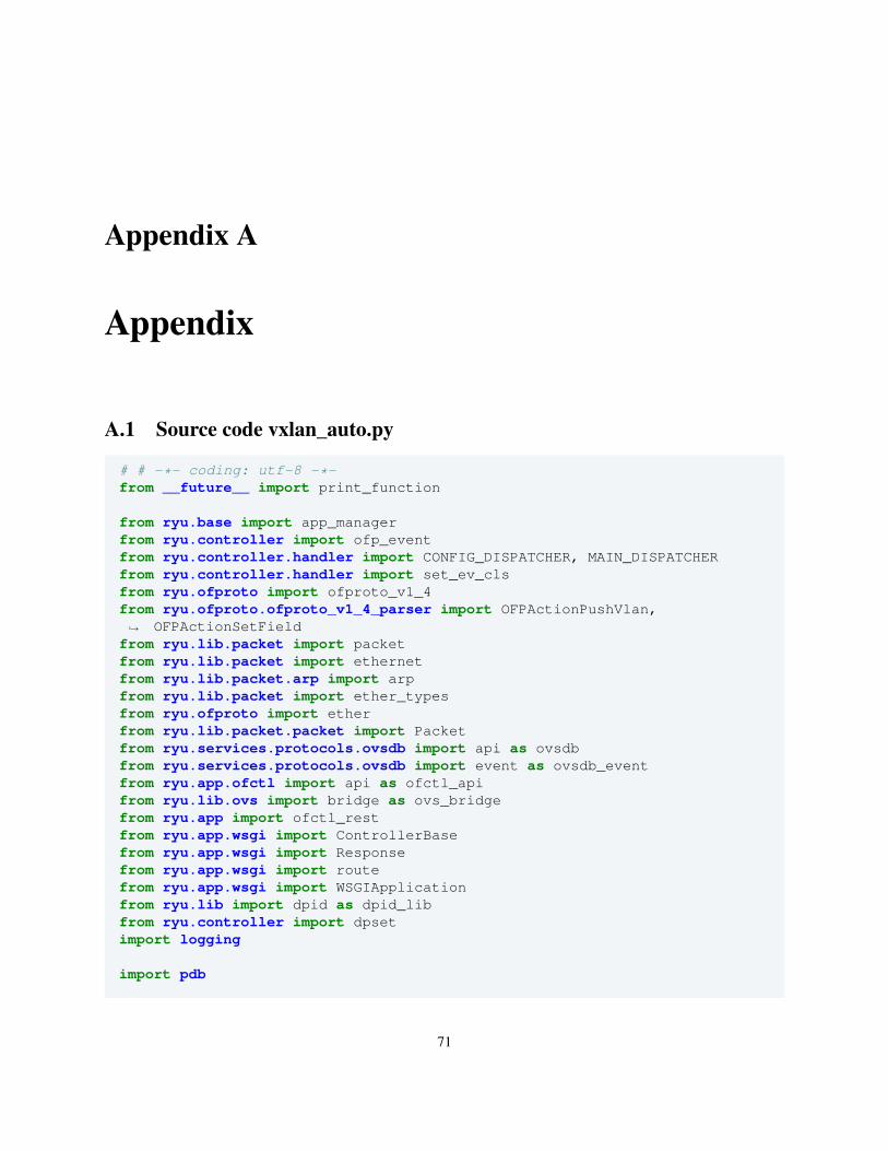
Appendix A
Appendix
A.1 Source code vxlan_auto.py
# # -*- coding: utf-8 -*-from __future__ import print_function
from ryu.base import app_managerfrom ryu.controller import ofp_eventfrom ryu.controller.handler import CONFIG_DISPATCHER, MAIN_DISPATCHERfrom ryu.controller.handler import set_ev_clsfrom ryu.ofproto import ofproto_v1_4from ryu.ofproto.ofproto_v1_4_parser import OFPActionPushVlan,
OFPActionSetField↪→
from ryu.lib.packet import packetfrom ryu.lib.packet import ethernetfrom ryu.lib.packet.arp import arpfrom ryu.lib.packet import ether_typesfrom ryu.ofproto import etherfrom ryu.lib.packet.packet import Packetfrom ryu.services.protocols.ovsdb import api as ovsdbfrom ryu.services.protocols.ovsdb import event as ovsdb_eventfrom ryu.app.ofctl import api as ofctl_apifrom ryu.lib.ovs import bridge as ovs_bridgefrom ryu.app import ofctl_restfrom ryu.app.wsgi import ControllerBasefrom ryu.app.wsgi import Responsefrom ryu.app.wsgi import routefrom ryu.app.wsgi import WSGIApplicationfrom ryu.lib import dpid as dpid_libfrom ryu.controller import dpsetimport logging
import pdb
71
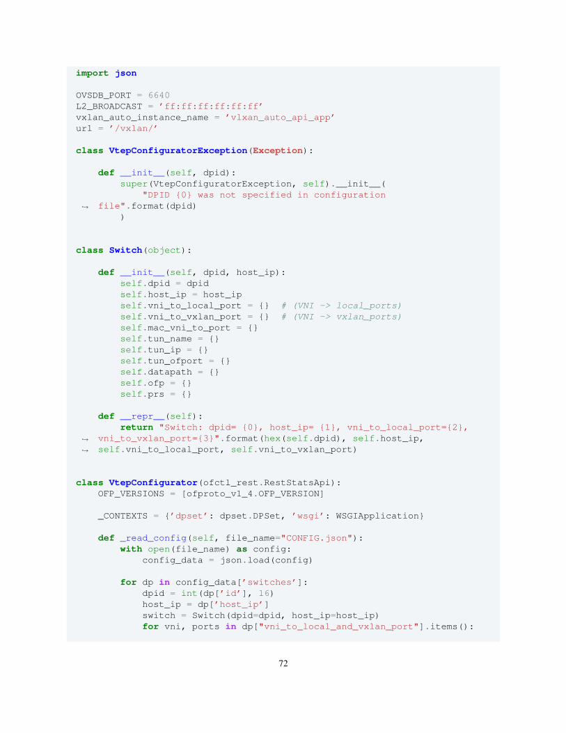
import json
OVSDB_PORT = 6640L2_BROADCAST = ’ff:ff:ff:ff:ff:ff’vxlan_auto_instance_name = ’vlxan_auto_api_app’url = ’/vxlan/’
class VtepConfiguratorException(Exception):
def __init__(self, dpid):super(VtepConfiguratorException, self).__init__(
"DPID {0} was not specified in configurationfile".format(dpid)↪→
)
class Switch(object):
def __init__(self, dpid, host_ip):self.dpid = dpidself.host_ip = host_ipself.vni_to_local_port = {} # (VNI -> local_ports)self.vni_to_vxlan_port = {} # (VNI -> vxlan_ports)self.mac_vni_to_port = {}self.tun_name = {}self.tun_ip = {}self.tun_ofport = {}self.datapath = {}self.ofp = {}self.prs = {}
def __repr__(self):return "Switch: dpid= {0}, host_ip= {1}, vni_to_local_port={2},
vni_to_vxlan_port={3}".format(hex(self.dpid), self.host_ip,self.vni_to_local_port, self.vni_to_vxlan_port)
↪→
↪→
class VtepConfigurator(ofctl_rest.RestStatsApi):OFP_VERSIONS = [ofproto_v1_4.OFP_VERSION]
_CONTEXTS = {’dpset’: dpset.DPSet, ’wsgi’: WSGIApplication}
def _read_config(self, file_name="CONFIG.json"):with open(file_name) as config:
config_data = json.load(config)
for dp in config_data[’switches’]:dpid = int(dp[’id’], 16)host_ip = dp[’host_ip’]switch = Switch(dpid=dpid, host_ip=host_ip)for vni, ports in dp["vni_to_local_and_vxlan_port"].items():
72
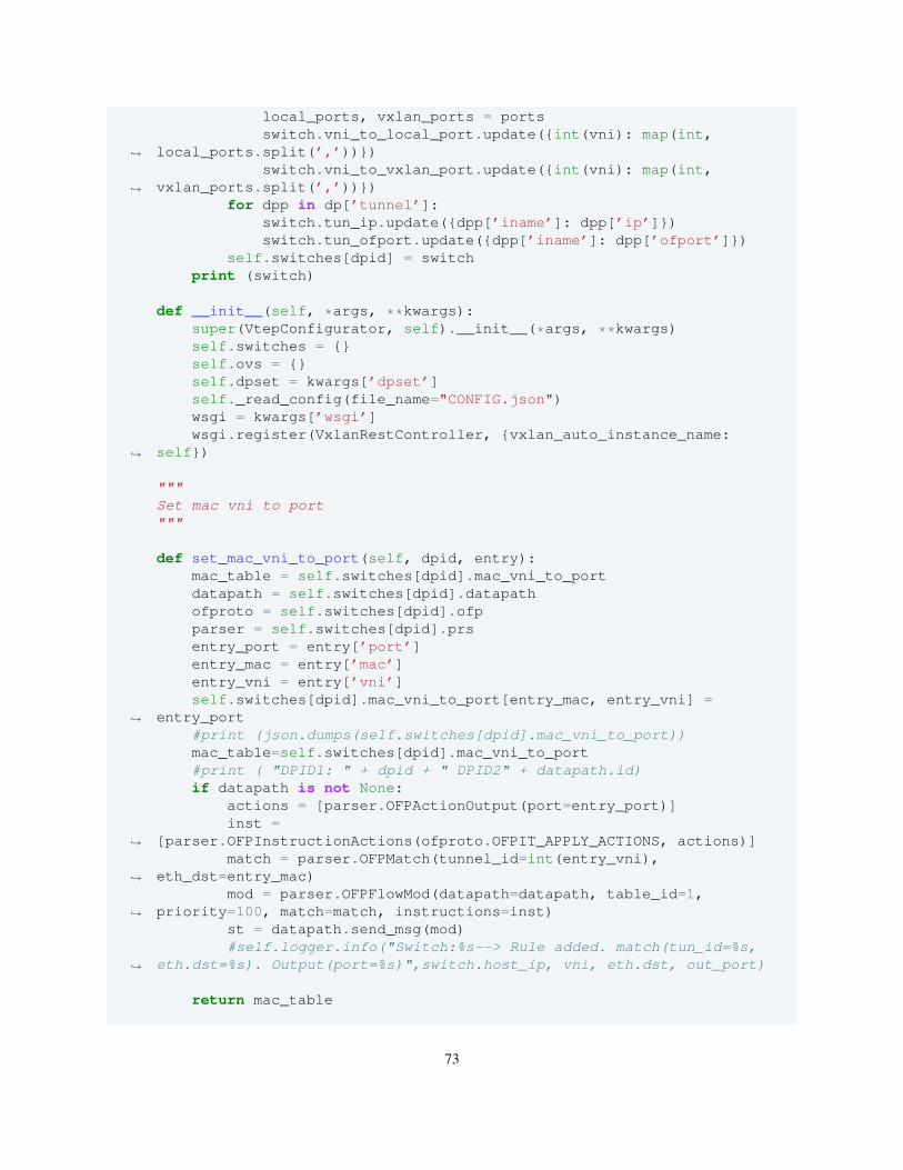
local_ports, vxlan_ports = portsswitch.vni_to_local_port.update({int(vni): map(int,
local_ports.split(’,’))})↪→
switch.vni_to_vxlan_port.update({int(vni): map(int,vxlan_ports.split(’,’))})↪→
for dpp in dp[’tunnel’]:switch.tun_ip.update({dpp[’iname’]: dpp[’ip’]})switch.tun_ofport.update({dpp[’iname’]: dpp[’ofport’]})
self.switches[dpid] = switchprint (switch)
def __init__(self, *args, **kwargs):super(VtepConfigurator, self).__init__(*args, **kwargs)self.switches = {}self.ovs = {}self.dpset = kwargs[’dpset’]self._read_config(file_name="CONFIG.json")wsgi = kwargs[’wsgi’]wsgi.register(VxlanRestController, {vxlan_auto_instance_name:
self})↪→
"""Set mac vni to port"""
def set_mac_vni_to_port(self, dpid, entry):mac_table = self.switches[dpid].mac_vni_to_portdatapath = self.switches[dpid].datapathofproto = self.switches[dpid].ofpparser = self.switches[dpid].prsentry_port = entry[’port’]entry_mac = entry[’mac’]entry_vni = entry[’vni’]self.switches[dpid].mac_vni_to_port[entry_mac, entry_vni] =
entry_port↪→
#print (json.dumps(self.switches[dpid].mac_vni_to_port))mac_table=self.switches[dpid].mac_vni_to_port#print ( "DPID1: " + dpid + " DPID2" + datapath.id)if datapath is not None:
actions = [parser.OFPActionOutput(port=entry_port)]inst =
[parser.OFPInstructionActions(ofproto.OFPIT_APPLY_ACTIONS, actions)]↪→
match = parser.OFPMatch(tunnel_id=int(entry_vni),eth_dst=entry_mac)↪→
mod = parser.OFPFlowMod(datapath=datapath, table_id=1,priority=100, match=match, instructions=inst)↪→
st = datapath.send_msg(mod)#self.logger.info("Switch:%s--> Rule added. match(tun_id=%s,
eth.dst=%s). Output(port=%s)",switch.host_ip, vni, eth.dst, out_port)↪→
return mac_table
73
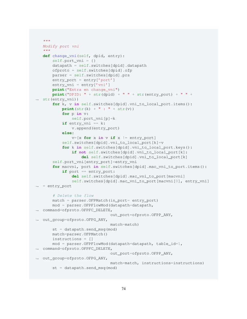
"""Modify port vni"""def change_vni(self, dpid, entry):
self.port_vni = {}datapath = self.switches[dpid].datapathofproto = self.switches[dpid].ofpparser = self.switches[dpid].prsentry_port = entry[’port’]entry_vni = entry[’vni’]print("Entra en change_vni")print("DPID: " + str(dpid) + " " + str(entry_port) + " " +
str(entry_vni))↪→
for k, v in self.switches[dpid].vni_to_local_port.items():print(str(k) + " : " + str(v))for p in v:
self.port_vni[p]=kif entry_vni == k:
v.append(entry_port)else:
v=[x for x in v if x != entry_port]self.switches[dpid].vni_to_local_port[k]=vfor k in self.switches[dpid].vni_to_local_port.keys():
if not self.switches[dpid].vni_to_local_port[k]:del self.switches[dpid].vni_to_local_port[k]
self.port_vni[entry_port]=entry_vnifor macvni, port in self.switches[dpid].mac_vni_to_port.items():
if port == entry_port:del self.switches[dpid].mac_vni_to_port[macvni]self.switches[dpid].mac_vni_to_port[macvni[0], entry_vni]
= entry_port↪→
# Delete the flowmatch = parser.OFPMatch(in_port= entry_port)mod = parser.OFPFlowMod(datapath=datapath,
command=ofproto.OFPFC_DELETE,↪→
out_port=ofproto.OFPP_ANY,out_group=ofproto.OFPG_ANY,↪→
match=match)st = datapath.send_msg(mod)match=parser.OFPMatch()instructions = []mod = parser.OFPFlowMod(datapath=datapath, table_id=1,
command=ofproto.OFPFC_DELETE,↪→
out_port=ofproto.OFPP_ANY,out_group=ofproto.OFPG_ANY,↪→
match=match, instructions=instructions)st = datapath.send_msg(mod)
74
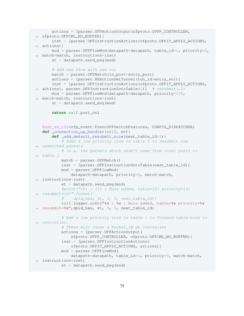
actions = [parser.OFPActionOutput(ofproto.OFPP_CONTROLLER,ofproto.OFPCML_NO_BUFFER)]↪→
inst = [parser.OFPInstructionActions(ofproto.OFPIT_APPLY_ACTIONS,actions)]↪→
mod = parser.OFPFlowMod(datapath=datapath, table_id=1, priority=0,match=match, instructions=inst)↪→
st = datapath.send_msg(mod)
# Add new flow with new vnimatch = parser.OFPMatch(in_port=entry_port)actions = [parser.NXActionSetTunnel(tun_id=entry_vni)]inst = [parser.OFPInstructionActions(ofproto.OFPIT_APPLY_ACTIONS,
actions), parser.OFPInstructionGotoTable(1)] # resubmit(,1)↪→
mod = parser.OFPFlowMod(datapath=datapath, priority=100,match=match, instructions=inst)↪→
st = datapath.send_msg(mod)
return self.port_vni
@set_ev_cls(ofp_event.EventOFPSwitchFeatures, CONFIG_DISPATCHER)def _connection_up_handler(self, ev):
def _add_default_resubmit_rule(next_table_id=1):# Adds a low priority rule in table 0 to resubmit the
unmatched packets↪→
# (i.e. the packets which didn’t come from local port) totable 1↪→
match = parser.OFPMatch()inst = [parser.OFPInstructionGotoTable(next_table_id)]mod = parser.OFPFlowMod(
datapath=datapath, priority=0, match=match,instructions=inst)↪→
st = datapath.send_msg(mod)#print("{0} : {1} : Rule added, table={2} priority={3}
resubmit={4}".format(↪→
# dpid_hex, st, 0, 0, next_table_id))self.logger.info("%s : %s : Rule added, table=%s priority=%s
resubmit=%s",dpid_hex, st, 0, 0, next_table_id)↪→
# Add a low priority rule in table 1 to forward table-miss tocontroller.↪→
# These will cause a Packet_IN at controlleractions = [parser.OFPActionOutput(
ofproto.OFPP_CONTROLLER, ofproto.OFPCML_NO_BUFFER)]inst = [parser.OFPInstructionActions(
ofproto.OFPIT_APPLY_ACTIONS, actions)]mod = parser.OFPFlowMod(
datapath=datapath, table_id=1, priority=0, match=match,instructions=inst)↪→
st = datapath.send_msg(mod)
75
self.logger.info("%s : %s : Rule added, table=%s priority=%sForward to CONTROLLER",dpid_hex, st, 1, 0)↪→
datapath = ev.msg.datapathdpid = datapath.iddpid_hex = hex(dpid)
if dpid not in self.switches: # if the dpid was not specified inCONFIG file↪→
raise VtepConfiguratorException(dpid)
ofproto = datapath.ofprotoparser = datapath.ofproto_parser# Forward all other packets to table 1 in packet processing
pipeline.↪→
_add_default_resubmit_rule(next_table_id=1)
# Switch will conatin all the information from CONFIG about this# particular datapathswitch = self.switches[dpid]for vni, ports in switch.vni_to_local_port.items():
for port in ports:# table=0,
in_port=<1>,actions=set_field:<100>->tun_id,resubmit(,1)↪→
# These rules will ensure that all the packets coming fromlocal ports↪→
# have tunnel_id associated with them, when packet# processing reaches table 1.match = parser.OFPMatch(in_port=port)actions = [parser.NXActionSetTunnel(tun_id=vni)]inst =
[parser.OFPInstructionActions(ofproto.OFPIT_APPLY_ACTIONS, actions),parser.OFPInstructionGotoTable(1)] # resubmit(,1)
↪→
↪→
mod = parser.OFPFlowMod(datapath=datapath, priority=100,match=match, instructions=inst)↪→
st = datapath.send_msg(mod)self.logger.info("%s : %s : Rule added, match(in_port=%s)
set_tun_id=%s, resubmit(%s)",dpid_hex, st, port, vni, 1)↪→
@set_ev_cls(ofp_event.EventOFPPacketIn, MAIN_DISPATCHER)def _packet_in_handler(self, ev):
msg = ev.msgdatapath = msg.datapathdpid = datapath.iddpid_hex = hex(dpid)if dpid not in self.switches:
raise VtepConfiguratorException(dpid)switch = self.switches[dpid]switch.datapath = datapathswitch.ofp = datapath.ofprotoswitch.prs = datapath.ofproto_parser
76
ofproto = datapath.ofprotoparser = datapath.ofproto_parserpkt = packet.Packet(msg.data)eth = pkt.get_protocols(ethernet.ethernet)[0]
if eth.ethertype == ether_types.ETH_TYPE_LLDP:return # ignore LLDP packet
in_port = msg.match[’in_port’]vni = msg.match[’tunnel_id’]self.logger.info("Switch:%s--> Received a packet on port=%s of VNI
ID=%s from eth_src=%s to eth_dst=%s",switch.host_ip, in_port, vni,eth.src, eth.dst)
↪→
↪→
# Save the (src_mac, VNI) -> port mapping in switchswitch.mac_vni_to_port[eth.src, vni] = in_port#print (json.dumps(switch.mac_vni_to_port))vxlan_ports = switch.vni_to_vxlan_port[vni][:] # Deep copy
if eth.dst == L2_BROADCAST:# If a broadcast packet has been received from a VXLAN tunnel
port then↪→
# multicast it on local ports.local_ports = switch.vni_to_local_port[vni][:]if in_port in vxlan_ports: # Incoming traffic
for port in local_ports: # Multicast on each local portsactions = [parser.OFPActionOutput(port=port)]out = parser.OFPPacketOut(datapath=datapath,
buffer_id=ofproto.OFP_NO_BUFFER, in_port=in_port,actions=actions,data=pkt)
↪→
↪→
st = datapath.send_msg(out)self.logger.info("Switch:%s--> Packet src=%s,
destination=%s, output=%s",switch.host_ip, eth.src, eth.dst, port)↪→
vxlan_ports.remove(in_port)# Coming from vxlan port and output in vxlan portfor port in vxlan_ports:
actions = [parser.NXActionSetTunnel(tun_id=vni),parser.OFPActionOutput(port=port)]↪→
out = parser.OFPPacketOut(datapath=datapath,buffer_id=ofproto.OFP_NO_BUFFER, in_port=in_port,actions=actions,data=pkt)
↪→
↪→
st = datapath.send_msg(out)self.logger.info("Switch:%s--> Packet output
in_port=%s setTunnelId=%s, out_port=%s",switch.host_ip, in_port, vni,port)
↪→
↪→
else: # Coming from local port, output on all VXLAN port andlocal port on the same VNI↪→
print("local ports-->>")print(local_ports)local_ports.remove(in_port)
77
for port in local_ports: # Forward on other local portsof the same VNI↪→
actions = [parser.OFPActionOutput(port=port)]out = parser.OFPPacketOut(datapath=datapath,
buffer_id=ofproto.OFP_NO_BUFFER, in_port=in_port, actions=actions,data=pkt)
↪→
↪→
st = datapath.send_msg(out)self.logger.info("Switch:%s--> Packet src=%s,
destination=%s, output=%s",switch.host_ip, eth.src, eth.dst, port)↪→
for port in vxlan_ports: # Multicast on all subscriberVXLAN ports.↪→
# Set tunnel ID and output on the VXLAN portsactions = [parser.NXActionSetTunnel(tun_id=vni),
parser.OFPActionOutput(port=port)]↪→
out = parser.OFPPacketOut(datapath=datapath,buffer_id=ofproto.OFP_NO_BUFFER, in_port=in_port,actions=actions,data=pkt)
↪→
↪→
st = datapath.send_msg(out)self.logger.info("Switch:%s--> Packet output
in_port=%s setTunnelId=%s, out_port=%s",switch.host_ip, in_port, vni,port)
↪→
↪→
else: # Unicast messageif in_port in vxlan_ports: # Incoming unicast message
try:out_port = switch.mac_vni_to_port[eth.dst, vni]
except KeyError as e:print(e)return
# Add rule for packets from local_ports to VXLAN_portsmatch = parser.OFPMatch(tunnel_id=vni, eth_dst=eth.dst)actions = [parser.OFPActionOutput(port=out_port)]inst = [parser.OFPInstructionActions(
ofproto.OFPIT_APPLY_ACTIONS, actions)]mod = parser.OFPFlowMod(datapath=datapath, table_id=1,
priority=100, match=match,↪→
instructions=inst)st = datapath.send_msg(mod)self.logger.info("Switch:%s--> Rule added.
match(tun_id=%s, eth.dst=%s). Output(port=%s)",switch.host_ip, vni,eth.dst, out_port)
↪→
↪→
# Add rule for packets from VXLAN_port to local_portmatch = parser.OFPMatch(tunnel_id=vni, eth_dst=eth.src)actions = [parser.OFPActionOutput(port=in_port)]inst = [parser.OFPInstructionActions(
ofproto.OFPIT_APPLY_ACTIONS, actions)]mod = parser.OFPFlowMod(datapath=datapath, table_id=1,
priority=100, match=match,↪→
instructions=inst)st = datapath.send_msg(mod)
78
self.logger.info("Switch:%s--> Rule added.match(tun_id=%s, eth.dst=%s). Output(port=%s)",switch.host_ip, vni,eth.src, in_port)
↪→
↪→
# Output the packetactions = [parser.OFPActionOutput(port=out_port)]out = parser.OFPPacketOut(datapath=datapath,
buffer_id=ofproto.OFP_NO_BUFFER, in_port=in_port,↪→
actions=actions, data=pkt)st = datapath.send_msg(out)self.logger.info("Switch:%s--> Outgoing traffic.
setTunnelId=%s out_port=%s",switch.host_ip, vni, out_port)↪→
else: # Outgoing unicast messagetry:
out_port = switch.mac_vni_to_port[eth.dst, vni]except KeyError as e:
print(e)return
# Add rule for packets from local_ports to VXLAN_portsmatch = parser.OFPMatch(tunnel_id=vni, eth_dst=eth.dst)actions = [parser.OFPActionOutput(port=out_port)]inst = [parser.OFPInstructionActions(
ofproto.OFPIT_APPLY_ACTIONS, actions)]mod = parser.OFPFlowMod(datapath=datapath, table_id=1,
priority=100, match=match,↪→
instructions=inst)st = datapath.send_msg(mod)self.logger.info("Switch:%s--> Rule added.
match(tun_id=%s, eth.dst=%s Output(port=%s)",switch.host_ip, vni,eth.dst, out_port)
↪→
↪→
# Add rule for packets from VXLAN_port to local_portmatch = parser.OFPMatch(tunnel_id=vni, eth_dst=eth.src)actions = [parser.OFPActionOutput(port=in_port)]inst = [parser.OFPInstructionActions(
ofproto.OFPIT_APPLY_ACTIONS, actions)]mod = parser.OFPFlowMod(datapath=datapath, table_id=1,
priority=100, match=match,↪→
instructions=inst)st = datapath.send_msg(mod)self.logger.info("Switch:%s--> Rule added.
match(tun_id=%s, eth.dst=%s Output(port=%s)",switch.host_ip, vni,eth.src, in_port)
↪→
↪→
# Output the packet on out_portactions = [parser.NXActionSetTunnel(
tun_id=vni),parser.OFPActionOutput(port=out_port)]↪→
out = parser.OFPPacketOut(datapath=datapath,buffer_id=ofproto.OFP_NO_BUFFER, in_port=in_port,↪→
79
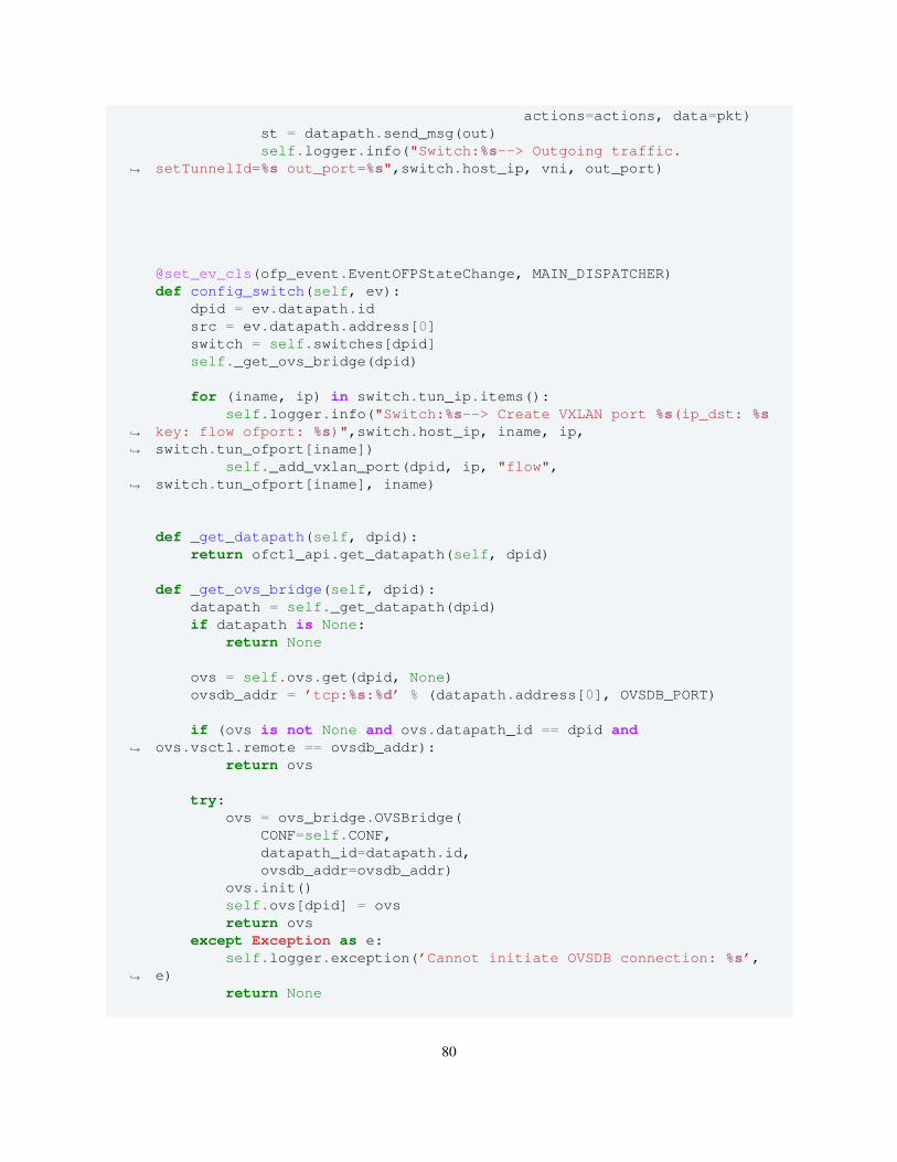
actions=actions, data=pkt)st = datapath.send_msg(out)self.logger.info("Switch:%s--> Outgoing traffic.
setTunnelId=%s out_port=%s",switch.host_ip, vni, out_port)↪→
@set_ev_cls(ofp_event.EventOFPStateChange, MAIN_DISPATCHER)def config_switch(self, ev):
dpid = ev.datapath.idsrc = ev.datapath.address[0]switch = self.switches[dpid]self._get_ovs_bridge(dpid)
for (iname, ip) in switch.tun_ip.items():self.logger.info("Switch:%s--> Create VXLAN port %s(ip_dst: %s
key: flow ofport: %s)",switch.host_ip, iname, ip,switch.tun_ofport[iname])
↪→
↪→
self._add_vxlan_port(dpid, ip, "flow",switch.tun_ofport[iname], iname)↪→
def _get_datapath(self, dpid):return ofctl_api.get_datapath(self, dpid)
def _get_ovs_bridge(self, dpid):datapath = self._get_datapath(dpid)if datapath is None:
return None
ovs = self.ovs.get(dpid, None)ovsdb_addr = ’tcp:%s:%d’ % (datapath.address[0], OVSDB_PORT)
if (ovs is not None and ovs.datapath_id == dpid andovs.vsctl.remote == ovsdb_addr):↪→
return ovs
try:ovs = ovs_bridge.OVSBridge(
CONF=self.CONF,datapath_id=datapath.id,ovsdb_addr=ovsdb_addr)
ovs.init()self.ovs[dpid] = ovsreturn ovs
except Exception as e:self.logger.exception(’Cannot initiate OVSDB connection: %s’,
e)↪→
return None
80
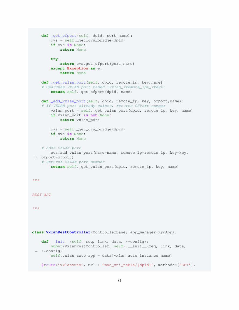
def _get_ofport(self, dpid, port_name):ovs = self._get_ovs_bridge(dpid)if ovs is None:
return None
try:return ovs.get_ofport(port_name)
except Exception as e:return None
def _get_vxlan_port(self, dpid, remote_ip, key,name):# Searches VXLAN port named ’vxlan_<remote_ip>_<key>’
return self._get_ofport(dpid, name)
def _add_vxlan_port(self, dpid, remote_ip, key, ofport,name):# If VXLAN port already exists, returns OFPort number
vxlan_port = self._get_vxlan_port(dpid, remote_ip, key, name)if vxlan_port is not None:
return vxlan_port
ovs = self._get_ovs_bridge(dpid)if ovs is None:
return None
# Adds VXLAN portovs.add_vxlan_port(name=name, remote_ip=remote_ip, key=key,
ofport=ofport)↪→
# Returns VXLAN port numberreturn self._get_vxlan_port(dpid, remote_ip, key, name)
"""
REST API
"""
class VxlanRestController(ControllerBase, app_manager.RyuApp):
def __init__(self, req, link, data, **config):super(VxlanRestController, self).__init__(req, link, data,
**config)↪→
self.vxlan_auto_app = data[vxlan_auto_instance_name]
@route(’vxlanauto’, url + ’mac_vni_table/{dpid}’, methods=[’GET’],
81
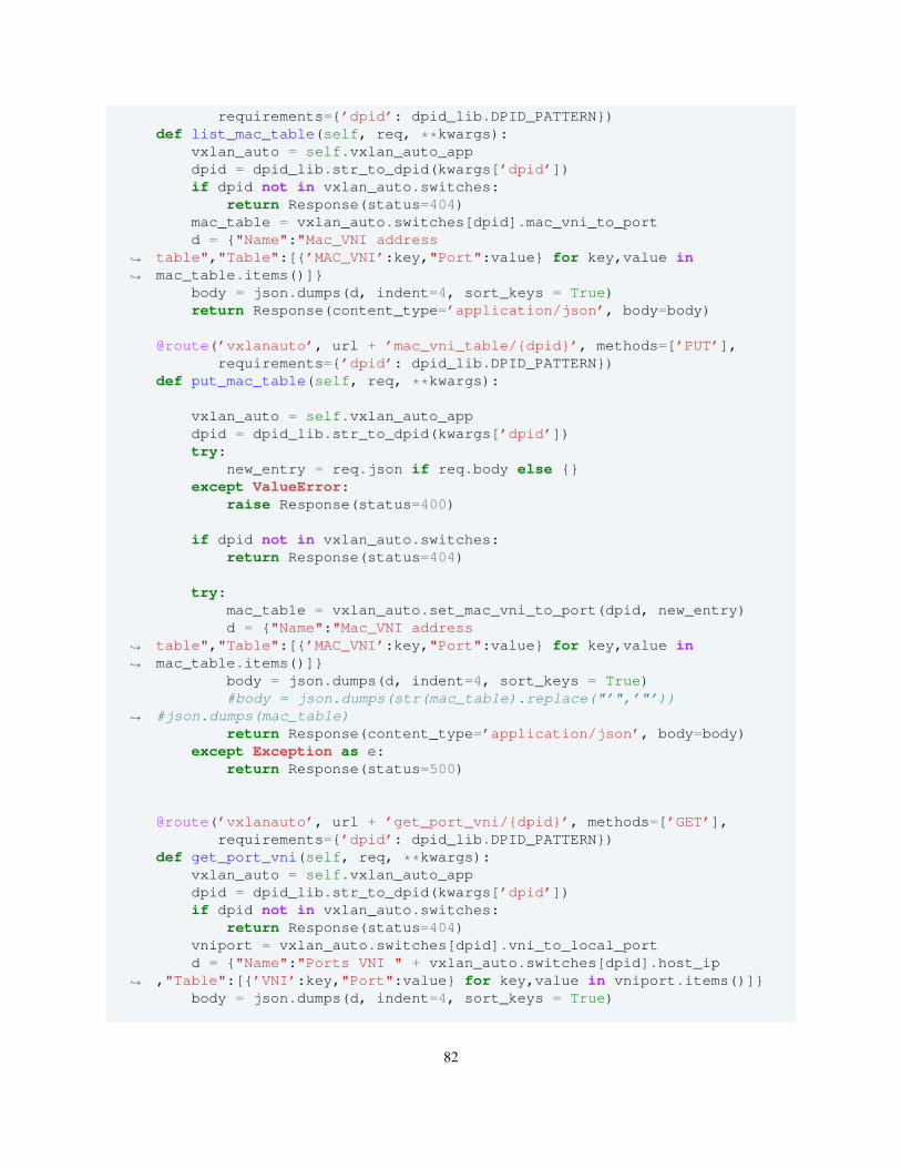
requirements={’dpid’: dpid_lib.DPID_PATTERN})def list_mac_table(self, req, **kwargs):
vxlan_auto = self.vxlan_auto_appdpid = dpid_lib.str_to_dpid(kwargs[’dpid’])if dpid not in vxlan_auto.switches:
return Response(status=404)mac_table = vxlan_auto.switches[dpid].mac_vni_to_portd = {"Name":"Mac_VNI address
table","Table":[{’MAC_VNI’:key,"Port":value} for key,value inmac_table.items()]}
↪→
↪→
body = json.dumps(d, indent=4, sort_keys = True)return Response(content_type=’application/json’, body=body)
@route(’vxlanauto’, url + ’mac_vni_table/{dpid}’, methods=[’PUT’],requirements={’dpid’: dpid_lib.DPID_PATTERN})
def put_mac_table(self, req, **kwargs):
vxlan_auto = self.vxlan_auto_appdpid = dpid_lib.str_to_dpid(kwargs[’dpid’])try:
new_entry = req.json if req.body else {}except ValueError:
raise Response(status=400)
if dpid not in vxlan_auto.switches:return Response(status=404)
try:mac_table = vxlan_auto.set_mac_vni_to_port(dpid, new_entry)d = {"Name":"Mac_VNI address
table","Table":[{’MAC_VNI’:key,"Port":value} for key,value inmac_table.items()]}
↪→
↪→
body = json.dumps(d, indent=4, sort_keys = True)#body = json.dumps(str(mac_table).replace("’",’"’))
#json.dumps(mac_table)↪→
return Response(content_type=’application/json’, body=body)except Exception as e:
return Response(status=500)
@route(’vxlanauto’, url + ’get_port_vni/{dpid}’, methods=[’GET’],requirements={’dpid’: dpid_lib.DPID_PATTERN})
def get_port_vni(self, req, **kwargs):vxlan_auto = self.vxlan_auto_appdpid = dpid_lib.str_to_dpid(kwargs[’dpid’])if dpid not in vxlan_auto.switches:
return Response(status=404)vniport = vxlan_auto.switches[dpid].vni_to_local_portd = {"Name":"Ports VNI " + vxlan_auto.switches[dpid].host_ip
,"Table":[{’VNI’:key,"Port":value} for key,value in vniport.items()]}↪→
body = json.dumps(d, indent=4, sort_keys = True)
82
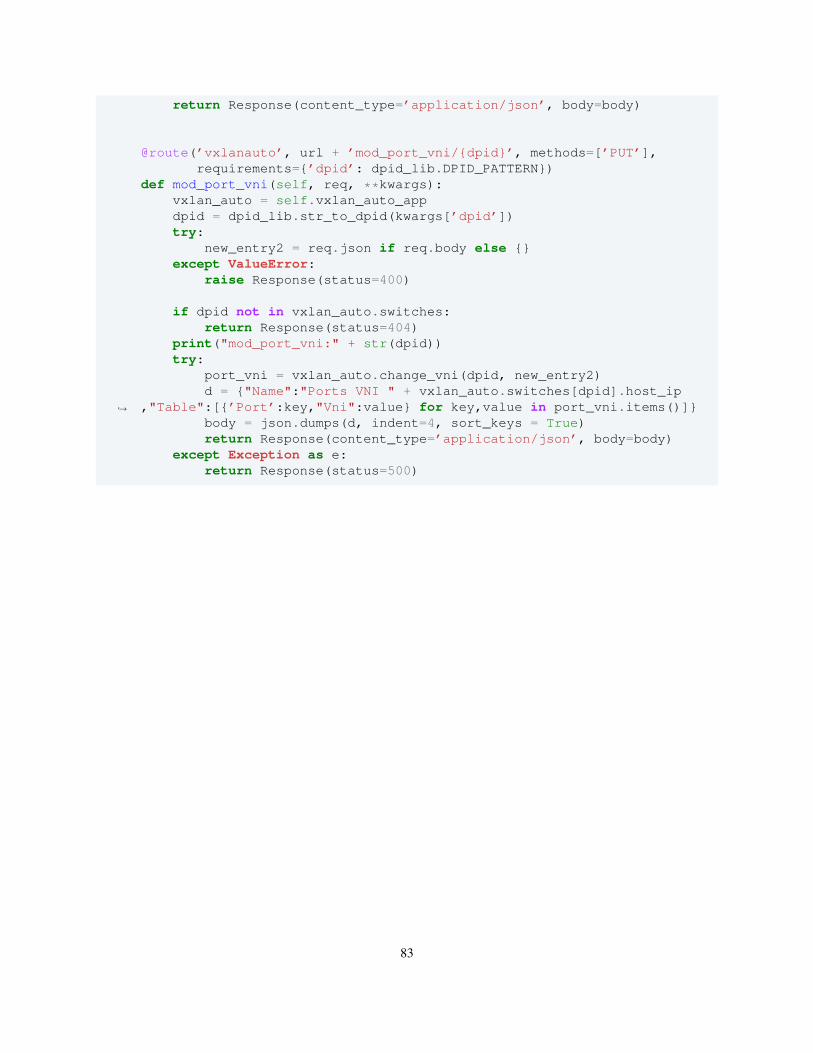
return Response(content_type=’application/json’, body=body)
@route(’vxlanauto’, url + ’mod_port_vni/{dpid}’, methods=[’PUT’],requirements={’dpid’: dpid_lib.DPID_PATTERN})
def mod_port_vni(self, req, **kwargs):vxlan_auto = self.vxlan_auto_appdpid = dpid_lib.str_to_dpid(kwargs[’dpid’])try:
new_entry2 = req.json if req.body else {}except ValueError:
raise Response(status=400)
if dpid not in vxlan_auto.switches:return Response(status=404)
print("mod_port_vni:" + str(dpid))try:
port_vni = vxlan_auto.change_vni(dpid, new_entry2)d = {"Name":"Ports VNI " + vxlan_auto.switches[dpid].host_ip
,"Table":[{’Port’:key,"Vni":value} for key,value in port_vni.items()]}↪→
body = json.dumps(d, indent=4, sort_keys = True)return Response(content_type=’application/json’, body=body)
except Exception as e:return Response(status=500)
83
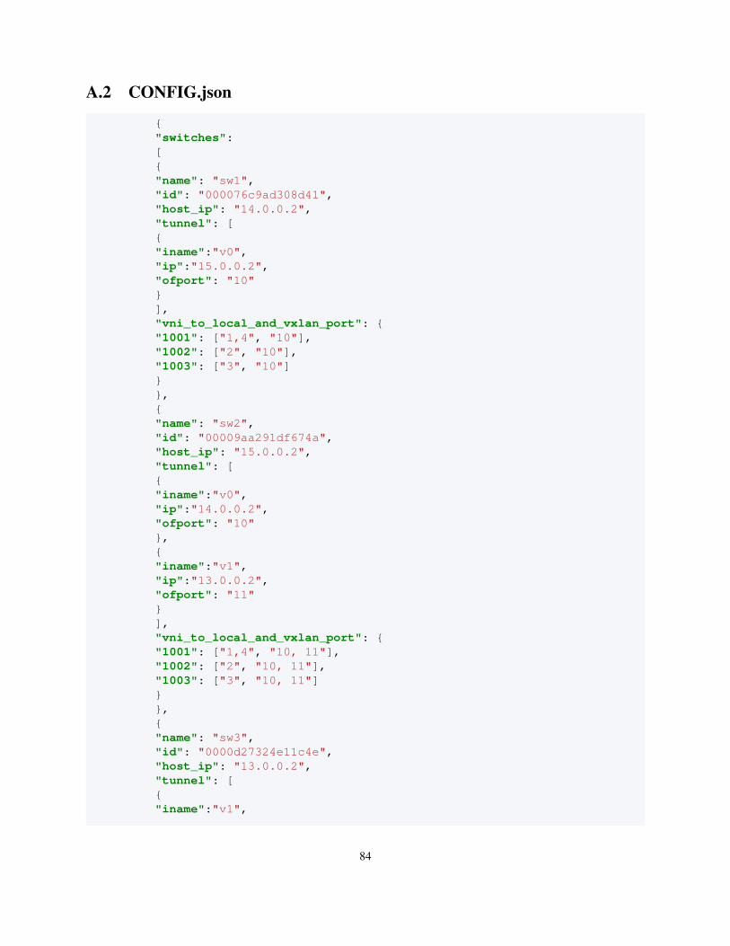
A.2 CONFIG.json
{"switches":[{"name": "sw1","id": "000076c9ad308d41","host_ip": "14.0.0.2","tunnel": [{"iname":"v0","ip":"15.0.0.2","ofport": "10"}],"vni_to_local_and_vxlan_port": {"1001": ["1,4", "10"],"1002": ["2", "10"],"1003": ["3", "10"]}},{"name": "sw2","id": "00009aa291df674a","host_ip": "15.0.0.2","tunnel": [{"iname":"v0","ip":"14.0.0.2","ofport": "10"},{"iname":"v1","ip":"13.0.0.2","ofport": "11"}],"vni_to_local_and_vxlan_port": {"1001": ["1,4", "10, 11"],"1002": ["2", "10, 11"],"1003": ["3", "10, 11"]}},{"name": "sw3","id": "0000d27324e11c4e","host_ip": "13.0.0.2","tunnel": [{"iname":"v1",
84
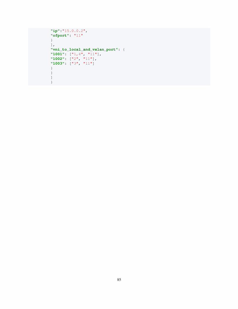
"ip":"15.0.0.2","ofport": "11"}],"vni_to_local_and_vxlan_port": {"1001": ["1,4", "11"],"1002": ["2", "11"],"1003": ["3", "11"]}}]}
85

86
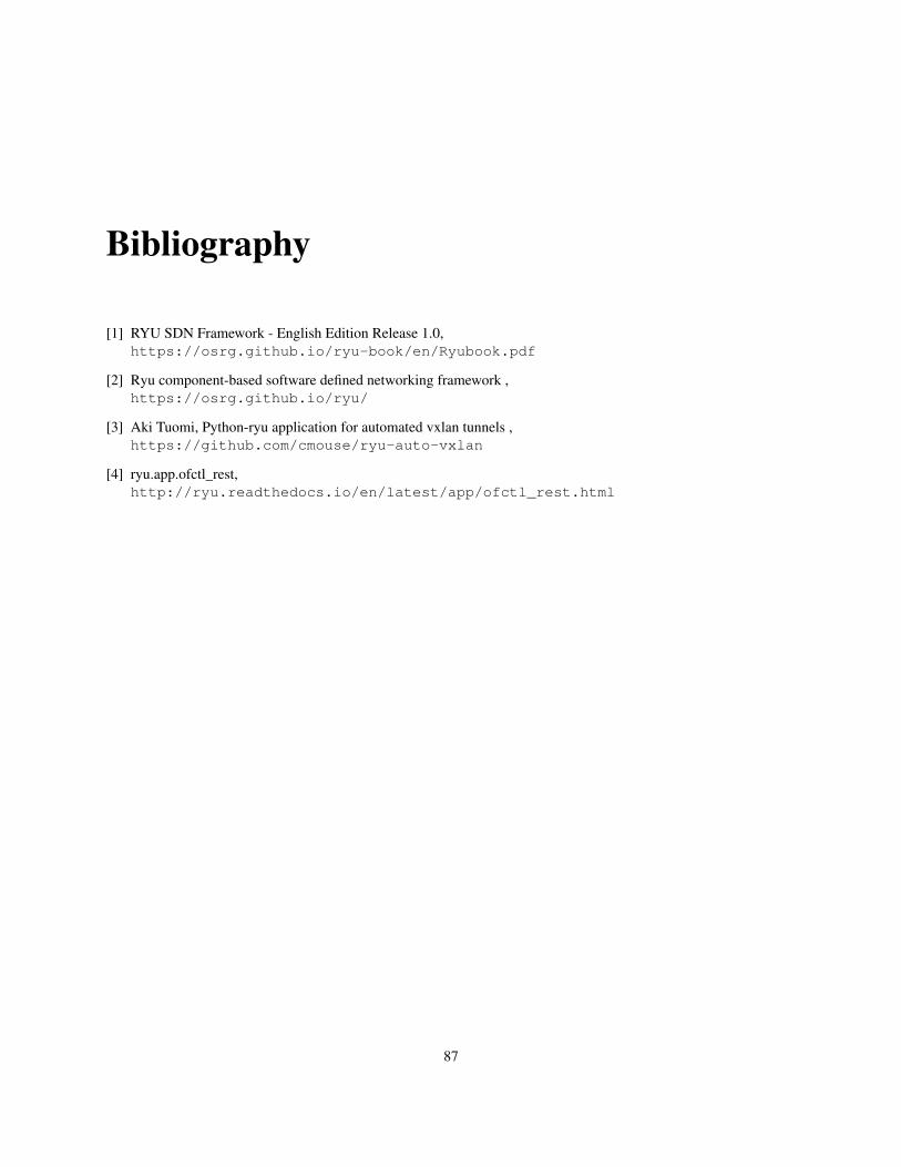
Bibliography
[1] RYU SDN Framework - English Edition Release 1.0,https://osrg.github.io/ryu-book/en/Ryubook.pdf
[2] Ryu component-based software defined networking framework ,https://osrg.github.io/ryu/
[3] Aki Tuomi, Python-ryu application for automated vxlan tunnels ,https://github.com/cmouse/ryu-auto-vxlan
[4] ryu.app.ofctl_rest,http://ryu.readthedocs.io/en/latest/app/ofctl_rest.html
87