Creating the Digital Negative
23
Creating the Digital Negative by George L Smyth There are many reasons darkroom photographers might have for creating digital negatives. It is great to know that I can shoot digitally, yet still print the digital image in the darkroom. Burning and dodging that would be impractical under the enlarger becomes a simple matter. In general, a new world is opened that allows for things previously not feasible. When creating a digital negative, a curve is applied to the image to adjust the negative’s tonalities so that they fit the paper. In one case, a friend gave me a stash of Kodak Ektalure paper, long ago discontinued. I have found this to be perfect paper to use with the Bromoil process, so by creating a digital negative not only can I maximize the value of this wonderful paper without having to waste any on test strips, but I can alter the contract of any image to fit this single contrast paper. This method can also be used with alternative processes, meaning that any digital image or scanned negative can be used with whatever process one wishes, and can be successfully printed the first time. This is important not only because of the time involved when utilizing an alternative process, but also because the expense of the process can be minimized, essential with platinum printing.
-
Upload
bjoern-wandels -
Category
Documents
-
view
33 -
download
3
Transcript of Creating the Digital Negative

Creating the Digital Negative
by George L Smyth
There are many reasons darkroom photographers might have for creating digital
negatives. It is great to know that I can shoot digitally, yet still print the digital image in
the darkroom. Burning and dodging that would be impractical under the enlarger
becomes a simple matter. In general, a new world is opened that allows for things
previously not feasible.
When creating a digital negative, a curve is applied to the image to adjust the negative’s
tonalities so that they fit the paper. In one case, a friend gave me a stash of Kodak
Ektalure paper, long ago discontinued. I have found this to be perfect paper to use with
the Bromoil process, so by creating a digital negative not only can I maximize the value
of this wonderful paper without having to waste any on test strips, but I can alter the
contract of any image to fit this single contrast paper.
This method can also be used with alternative processes, meaning that any digital image
or scanned negative can be used with whatever process one wishes, and can be
successfully printed the first time. This is important not only because of the time
involved when utilizing an alternative process, but also because the expense of the
process can be minimized, essential with platinum printing.

Once a curve is matched to the paper, it makes no difference whether the original image
is digital or a scanned negative. If the image is correct on the screen, it can be printed in
the darkroom with a single exposure.
The most important element of creating a digital negative is to match the image's curve to
the paper and process. Simply reversing the image and printing it on a clear film will not
yield proper results, as there is not a one to one relationship between the tonality on the
screen and on the darkroom print. This article explains the steps taken to achieve a
proper relationship.
Making The Digital Negative
It is essential that the process is repeatable. The head of the enlarger should always be set
at the same height and aperture, the developer must remain the same, and all other
sections of the process should be consistent. Changing any part of the process will affect
the established curve, which will in turn affect the image's tonality.
This creation of the curve is the trickiest and most time consuming part of the matching
process. Once done, however, it is fixed as long as the process and materials remain the
same. The steps in creating the curve are:
1. Determine the exposure time
2. Determine the color of the negative

3. Determine the placement of the white point
4. Determine the placement of the other curve points
I am going to explain the steps I go through in establishing a curve for Kentmere
Fineprint paper.
Determine the exposure time
A proper exposure time ensures that the black areas of the image will offer full blacks on
the print. The negative, of course, will be clear so make a test strip to find the DMax
point by exposing the paper through Pictorico Premium OHP Transparency Film
(http://www.bhphotovideo.com/c/product/544997-
REG/Pictorico_TPU100_LTR_20_TPU_100_Premium_OHP_Transparency.html).
There are other products available, but at this point none offer the same quality with a
price advantage, and are not as universally available.
Set the height of the enlarger head to cover the largest size print expected to be made.
Stop the aperture down several stops to ensure a long exposure time. I generally attempt
to find a time of at least 30-60 seconds to minimize any variations that might occur to the
intensity of the light during exposure.
If using variable contrast paper, it may not be necessary to use a contrast filter in the
enlarger. As my intention is to use the exposed paper to make Bromoil prints as well as

straight prints, inclusion of a contrast filter allows me to use one filter for the latter, then
change to a lower contrast grade for the former.
When making the test strip, include a final section where the darkroom lights have been
turned on to ensure the paper’s maximum black for comparison.
Below is a scan of my test strip after I washed and dried it
At times there can be difficulty in figuring out the exact point where maximum black is
obtained. Photoshop can perform this task, which will be a continuing part of the
procedure. The scanned image is converted to Grayscale (Image -> Mode -> Grayscale),
the Info palette is opened (if it is not visible Window -> Info), and the Eyedropper tool is
selected by pressing the letter "i". In the settings at the top of the window, change "Point

Sample" to "11 by 11 Average". This is done because there will be small deviations
within the segments, so this setting will take the measurement of an 11 pixel square and
present its average. When making measurements, the areas in the test strip can have
small variances, so this selection will display as average in the info palette.
Moving the eyedropper tool over the image will offer a percent value next to the letter
"K" in the Info palette - the higher the value, the darker the black value. Force this
section of maximum black to 100%. This is done by bringing up the Curves window
(Image -> Adjustments -> Curves or Ctrl-M). Below the graph are three eyedroppers -
click on the black eyedropper on the left. Click on the section of maximum black, which
will force it to 100%, and accordingly adjust the other sections.
Now when the eyedropper is moved to the other areas they will show values relative to
the maximum black on the test strip. If the test strip area reads within a couple percent of
the final section then that may be a good choice to consider to be maximum black. It is
best not to expose longer than necessary, as that could affect the ability to get a nice clean
white value.
Using the initial values, make a second test strip to more closely determine the point
where maximum black begins.

Determine the color of the negative
One might intuitively think that the color black would offer the greatest ability to block
light. However, various papers respond to portions of the light spectrum in different
ways, so black may not be the best color..

Dan Burkholder is a master of creating digital negatives and offers a very nice color chart
that can be used to help find the proper color. It can be found at
http://danburkholder.com/digital-negative-items-2008 - just download and unzip
spectrum.jpg.zip.
This is printed onto a sheet of the Pictorico OCP film and then contact printed against the
paper of choice for the time determined above. Process and dry, and scan the paper.

It is quite possible that the lightest areas are not where the DMax values are located. The
way to have Photoshop determine where the lightest value in the image is located is to
use the Threshold window (Image -> Adjustments -> Threshold). This offers the image
using only black and white pixels, nothing in between. The slider below the graph
indicates the gray point value where a pixel's value is determined to go one way or the
other.
Slide the nub all the way to the right, and then begin moving it slowly to the left. At
some point a patch of white will appear.
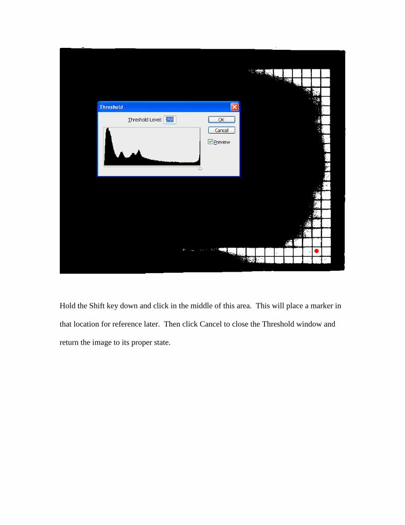
Hold the Shift key down and click in the middle of this area. This will place a marker in
that location for reference later. Then click Cancel to close the Threshold window and
return the image to its proper state.
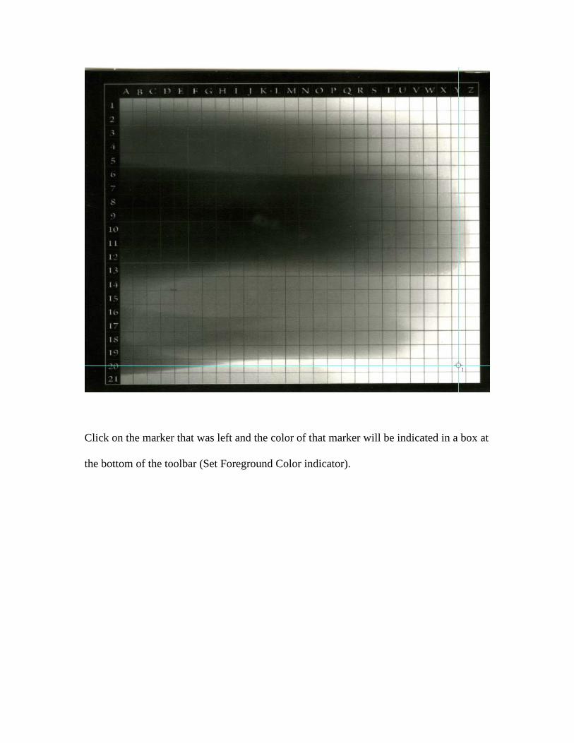
Click on the marker that was left and the color of that marker will be indicated in a box at
the bottom of the toolbar (Set Foreground Color indicator).

Click the color in the tool bar to display the Color Picker, showing the six digit
hexadecimal RGB value in the middle at the bottom, within the box next to the pound
sign (#). That will be the color of the negative.
Use the eyedropper to compare its value with the portion of the test strip that was
covered. If the values are not close then it can be seen how far the negative is from
having a clean white. It may be necessary to go back to the test strip that determined the
amount of exposure time and consider whether or not it is possible to reduce that time.

Determine the placement of the white point
The tonal values on the monitor do not directly relate to what the paper offers, so we need
to apply an adjustment layer to the image to compensate for these differences.
Once the curve is set, it is then just a matter of inverting (changing from a positive to a
negative) and colorizing the image.
When reviewing the curve, the value in the lower left corner represents absolute black, so
when it is inverted it will print clear - no ink - giving us the blackest value possible on the
paper, the same value we initially determined when we tested for exposure time.
The value in the upper of the curve represents the white point, the point where, when
inverted, will apply the greatest amount of ink. For many papers this point will already
be set, but for others this white point will actually be placed at a lower value.
Testing for this point, as well as all of the other points, requires the use of a step tablet.
You can either make your own or download the one I have available at
http://GLSmyth.com/Graphics/StepTablet.jpg. I have chosen to present 13 steps - 0%,

5%, 10%, 20%, 30%, 40%, 50%, 60%, 70%, 80%, 90%, 95%, and 100%. The procedure
will be to contact print the step tablet, the print will then be scanned, the sections
measured, and the values compared with the market percentages on the step tablet.
Altering the points on the adjustment curve to the step tablet will change its tonal values,
and the procedure will be iterated until the measured values are close to the step tablet’s
displayed percentage values.
The process is started by flipping the entire image horizontally (Image -> Rotate Canvas -
> Flip Canvas Horizontal), as the side of the negative on which we will be printing will
be the side in contact with the paper. Add three adjustment layers to the step tablet, a
Curves adjustment layer (Layer -> New Adjustment Layer -> Curves), an inversion layer
of the image (Layer -> New Adjustment Layer -> Invert), and a color fill layer (Layer ->
New Fill Layer -> Solid Color). The color of the Fill layer should be the color deemed
appropriate earlier, so this value should be entered.
This produces a solid color, but what is needed is for the color to be blended with the
image. This is done by selecting the color fill layer in the layers pallet and changing the
layer’s blending mode from Normal to Color.
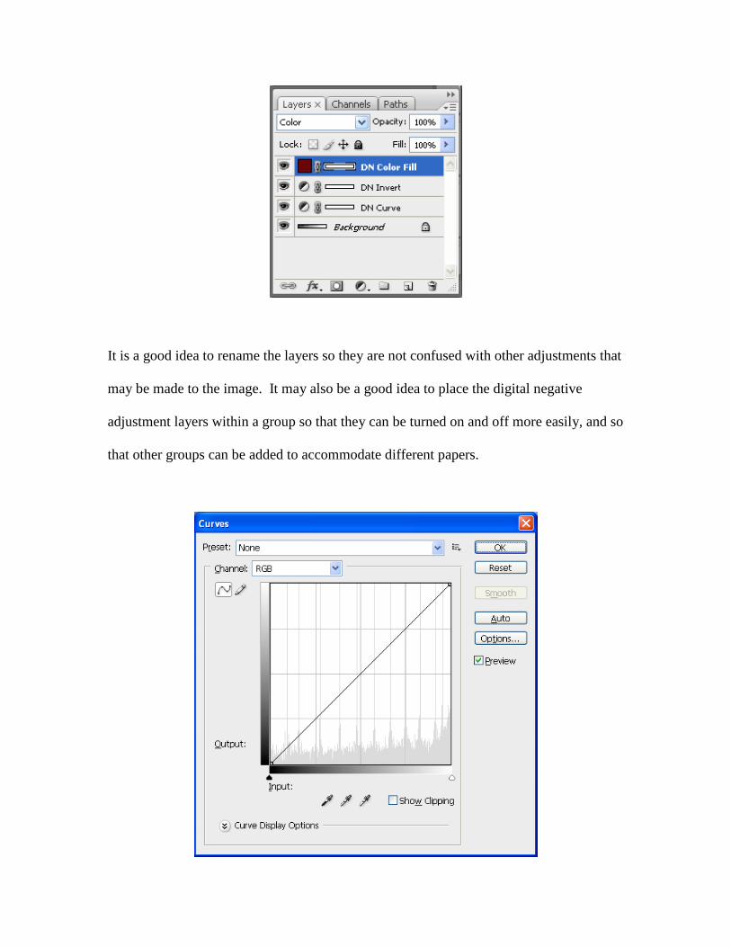
It is a good idea to rename the layers so they are not confused with other adjustments that
may be made to the image. It may also be a good idea to place the digital negative
adjustment layers within a group so that they can be turned on and off more easily, and so
that other groups can be added to accommodate different papers.

To examine the Curves adjustment layer, double-click the Curves layer icon and examine
it. Were there no image below it, this window would simply be a series of sixteen boxes
and a diagonal line. As we have the step tablet below this layer, included is a histogram
that represents the values in the image. The most important aspect of this is the
numerous spikes that show as vertical lines. This is a result of the large blocks of values,
so the first spike relates to the 95% value, the next to the 90% value, and so on. The
curve is alteres by moving adjustment points, which I refer to as nubs.
To create a nub, click on each point where the diagonal line intersects with a spike.

When, when creating a nub, if the line does not remain straight, its location can be altered
using the arrow keys.
With a nub at each intersection, the idea is to change the Output value of each nub,
altering the negative’s tonal representation. A nub is selected by pressing the – or +. The
nub will change from white to black, indicating that it is selected. Pressing the – or + key
moves the edit point from one nub to the next.
To determine the proper white point for the paper, the output value of the nubs (with the
exception of the first and last points) will be changed to different potential white point
values. Increasing the Output value of a point results in it representing a lighter value on
the paper point (remember that since we are working with a negative, when I refer to the
black point, it will actually be white in the negative, resulting in black on the paper).
To change an Output value without altering the Input value, always either enter the new
value in the Output text box or use the arrow key. Press the + key to select the second
nub. Change the Output value to 200. Click OK.

The step tablet is now ready to be printed on the transparency film. Pictorico suggests
that the printer driver be set to print on glossy paper. As the transparency film is not
inexpensive, I size the image of the step tablet to 4.2” across and set it to print in the
upper left corner. The step tablet will be printed over and over, and each time it can be
printed either to the left or below the previous step tablet, so testing can be completed on
a single sheet.
Although the transparency film will be dry to the touch when it comes out of the printer,
it will be several minutes before it is completely dry, and I have found that this makes a
difference in the darkroom. I hasten the process by using a hair dryer on the fan setting
(no heat).

Contact print the step tablet. There is no need to use a full sheet of paper, cut a piece
large enough to cover the step tablet. Develop, stop, and fix the paper. As the test strip
has no archival value, a short fix and a dozen seconds of wash are all that is necessary. A
hair dryer on full heat can be used to dry the test strip.
Scan the test strip. The color information only gets in the way, so convert the strip to
grayscale (Image -> Mode -> Grayscale). The strip will be mostly white with a black
rectangle in the 100% region. The easiest way to determine which square holds the
maximum value of white is to measure each rectangle using the Eyedropper tool. Make
sure that the sample size is set to "11 by 11 average." The segment that shows the
smallest value holds the most pure value of white.
Note the percentage displayed in the segment, return to the test strip, and bring up the
curve layer. Press the + key to select the nub that holds the location of the point of the
measured segment and read the value of the Output. For instance, if you found that the
20% segment of the scanned test strip held the smallest value of K, that would correspond
to the 4th nub from the upper right, and the Output value should be 240. This is the
output value that should be set on the nub representing the white point.

Determine the placement of the curve points
This section will take the longest to perform. However, once done, you will have
everything you need to make a digital negative for your selected paper. As the value of
the white point was determined in the previous step, it should be applied to the curve.
Select the rightmost nub and change the Output value to the value that was found as the
white point. In our example, the rightmost nub value would be changed from 255 to 240.
Press - to go to the next nub to the left of this nub and change its value to a value less
than the previous nub. Continue doing this until you reach the leftmost nub, as its value
will remain at zero. These initial values do not matter; just give the curve a generally
downward slant. Either write the Output value of each point on a piece of paper or enter
them into a spreadsheet. Using a spreadsheet makes it easier to compare the iterative.
Vertically enter the percentage values shown on the step tablet, from 100% to 0%. In a
column to the right enter the corresponding Output values that were entered.
Click OK, print the step tablet on the film below the one that was printed to find the
white point, contact print, develop, stop, fix, wash, dry, and scan.
Convert the scanned test strip to Grayscale. One difficulty that may arise would be that if
the paper has an off white base, the white value will never be close to 0%, so that will
make it very difficult to make comparisons. The solution is to force the 0% segment to
0%. Bring up the curve adjustment and click on the white dropper below the curve.

Click within the 0% segment, which will force that section to full white. Additionally,
make sure that the back segment shows as complete black by clicking the black dropper
and clicking within the 100% segment.
Measure the K value of each segment and enter the measured values in a column to the
right of the corresponding percentage. The end points will be close to the 0%/100%
rows, but the other values will vary considerably from the values in the leftmost column.
The idea is to get these two values close.
Begin another column and enter the Output values of the white and black points, as they
will remain constant throughout this process. Look to see which measured values come
close to the target values. For instance, the 30% segment may have measured 52%.
Enter the Output value for this segment into the 50% section. Do this for any other
sections that may give clues as to what the eventual values will actually be. Once done,
there will be a number of values that will need to be guessed, so enter guesses to fill the
column. Now go to the adjustment curve and press + to move to each nub and enter the
guessed Output values. Go back four paragraphs and repeat the process.
Eventually the percentages in the left column and the measured values will become close.
There is a point of diminishing returns with this process, so getting values that are close
to matching is the goal. There are so many variables out of your control that getting an
exact match for each section will not happen. In the adjustment curve window click on
the three lines to the left of the OK button and choose Save Preset. My recommendation

is to save the curve with a descriptive filename that includes the paper for which the
curve was crafter, for instance, Curve for Agfa MCC118, and of course, remember where
the preset is saved.
Making A Print
The production of a print from a digital negative is rather straightforward.
1. Flip the image, as the printed side of the negative will lie against the paper – do
this by Image -> Rotate Canvas -> Flip Canvas Horizontal
2. Load the curve established for the paper – Layer -> New Adjustment Layer ->
Curves – OK – click the three lines to the left of the OK button and choose Load
Preset – select the curve
3. Invert the image by adding an adjustment layer – Layer -> New Adjustment Layer
-> Invert
4. Add a Color Fill layer to colorize the negative – Layer -> New Fill Layer -> Solid
Color – change the color of the fill to the color that was determined in the
calibration process – change the blending mode of the layer from Normal to Color
My suggestion at this point is to increase the size of the canvas (Image -> Canvas Size)
and place a copy of the step tablet within the space. By doing this, if the print does not
look right when it is made, the step tablet is available to assist with troubleshooting..

Print the image on Pictorico Premium OHP Transparency Film, lay the film, inked side
down, on top of the paper in the darkroom, place a sheet of glass over both, and make the
exposure.
Additional Thoughts
Digital negatives can open a number of possibilities to the darkroom worker. It is a fact
that there are things that can be done, like burning and dodging that just are not possible
under the enlarger. This means that a negative can be scanned, adjusted in Photoshop,
and then printed in the darkroom as a straight print. It also means that a negative that

would never have fit on the single grade paper sitting on the shelf can do so after being
adjusted in Photoshop and a digital negative created from the effort. If, like me, you have
paper that is no longer made and is dear to your heart, then exposing through a digital
negative will make the most efficient use of your remaining stock.
If nothing else, this is another possibility that should be considered when trying to decide
how best to express one’s self through a darkroom created print.