CREATING OF THE PRIMITIVE SHAPES USING AUTOCAD Article 2 - BRAILA... · Conference on Engineering...
4
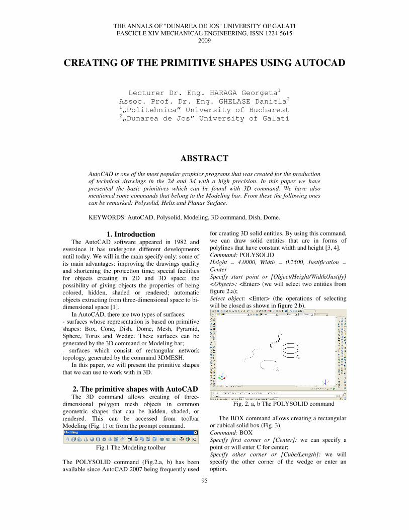
THE ANNALS OF "DUNAREA DE JOS" UNIVERSITY OF GALATI FASCICLE XIV MECHANICAL ENGINEERING, ISSN 1224-5615 2009 95 CREATING OF THE PRIMITIVE SHAPES USING AUTOCAD Lecturer Dr. Eng. HARAGA Georgeta 1 Assoc. Prof. Dr. Eng. GHELASE Daniela 2 1 „Politehnica” University of Bucharest 2 „Dunarea de Jos” University of Galati ABSTRACT AutoCAD is one of the most popular graphics programs that was created for the production of technical drawings in the 2d and 3d with a high precision. In this paper we have presented the basic primitives which can be found with 3D command. We have also mentioned some commands that belong to the Modeling bar. From these the following ones can be remarked: Polysolid, Helix and Planar Surface. KEYWORDS: AutoCAD, Polysolid, Modeling, 3D command, Dish, Dome. 1. Introduction The AutoCAD software appeared in 1982 and eversince it has undergone different developments until today. We will in the main specify only: some of its main advantages: improving the drawings quality and shortening the projection time; special facilities for objects creating in 2D and 3D space; the possibility of giving objects the properties of being colored, hidden, shaded or rendered; automatic objects extracting from three-dimensional space to bi- dimensional space [1]. In AutoCAD, there are two types of surfaces: - surfaces whose representation is based on primitive shapes: Box, Cone, Dish, Dome, Mesh, Pyramid, Sphere, Torus and Wedge. These surfaces can be generated by the 3D command or Modeling bar; - surfaces which consist of rectangular network topology, generated by the command 3DMESH. In this paper, we will present the primitive shapes that we can use to work with in 3D. 2. The primitive shapes with AutoCAD The 3D command allows creating of three- dimensional polygon mesh objects in common geometric shapes that can be hidden, shaded, or rendered. This can be accessed from toolbar Modeling (Fig. 1) or from the prompt command. Fig.1 The Modeling toolbar The POLYSOLID command (Fig.2.a, b) has been available since AutoCAD 2007 being frequently used for creating 3D solid entities. By using this command, we can draw solid entities that are in forms of polylines that have constant width and height [3, 4]. Command: POLYSOLID Height = 4.0000, Width = 0.2500, Justification = Center Specify start point or [Object/Height/Width/Justify] <Object>: <Enter> (we will select two entities from figure 2.a); Select object: <Enter> (the operations of selecting will be closed as shown in figure 2.b). Fig. 2. a, b The POLYSOLID command The BOX command allows creating a rectangular or cubical solid box (Fig. 3). Command: BOX Specify first corner or [Center]: we can specify a point or will enter C for center; Specify other corner or [Cube/Length]: we will specify the other corner of the wedge or enter an option.
Transcript of CREATING OF THE PRIMITIVE SHAPES USING AUTOCAD Article 2 - BRAILA... · Conference on Engineering...
THE ANNALS OF "DUNAREA DE JOS" UNIVERSITY OF GALATI
FASCICLE XIV MECHANICAL ENGINEERING, ISSN 1224-5615
2009
95
CREATING OF THE PRIMITIVE SHAPES USING AUTOCAD
Lecturer Dr. Eng. HARAGA Georgeta1
Assoc. Prof. Dr. Eng. GHELASE Daniela2
1„Politehnica” University of Bucharest
2„Dunarea de Jos” University of Galati
ABSTRACT
AutoCAD is one of the most popular graphics programs that was created for the production
of technical drawings in the 2d and 3d with a high precision. In this paper we have
presented the basic primitives which can be found with 3D command. We have also
mentioned some commands that belong to the Modeling bar. From these the following ones
can be remarked: Polysolid, Helix and Planar Surface.
KEYWORDS: AutoCAD, Polysolid, Modeling, 3D command, Dish, Dome.
1. Introduction The AutoCAD software appeared in 1982 and
eversince it has undergone different developments
until today. We will in the main specify only: some of
its main advantages: improving the drawings quality
and shortening the projection time; special facilities
for objects creating in 2D and 3D space; the
possibility of giving objects the properties of being
colored, hidden, shaded or rendered; automatic
objects extracting from three-dimensional space to bi-
dimensional space [1].
In AutoCAD, there are two types of surfaces:
- surfaces whose representation is based on primitive
shapes: Box, Cone, Dish, Dome, Mesh, Pyramid,
Sphere, Torus and Wedge. These surfaces can be
generated by the 3D command or Modeling bar;
- surfaces which consist of rectangular network
topology, generated by the command 3DMESH.
In this paper, we will present the primitive shapes
that we can use to work with in 3D.
2. The primitive shapes with AutoCAD The 3D command allows creating of three-
dimensional polygon mesh objects in common
geometric shapes that can be hidden, shaded, or
rendered. This can be accessed from toolbar
Modeling (Fig. 1) or from the prompt command.
Fig.1 The Modeling toolbar
The POLYSOLID command (Fig.2.a, b) has been
available since AutoCAD 2007 being frequently used
for creating 3D solid entities. By using this command,
we can draw solid entities that are in forms of
polylines that have constant width and height [3, 4].
Command: POLYSOLID
Height = 4.0000, Width = 0.2500, Justification =
Center
Specify start point or [Object/Height/Width/Justify]
<Object>: <Enter> (we will select two entities from
figure 2.a);
Select object: <Enter> (the operations of selecting
will be closed as shown in figure 2.b).
Fig. 2. a, b The POLYSOLID command
The BOX command allows creating a rectangular
or cubical solid box (Fig. 3).
Command: BOX
Specify first corner or [Center]: we can specify a
point or will enter C for center;
Specify other corner or [Cube/Length]: we will
specify the other corner of the wedge or enter an
option.
FASCICLE XIV THE ANNALS OF “DUNAREA DE JOS” UNIVERSITY OF GALATI
96
Fig. 3 The BOX command
The WEDGE command creates 3D solid wedge as
shown in figure 4. The WEDGE syntax is similar to
the BOX command.
Fig. 4 The WEDGE command
The CONE command allows drawing some cones
and trunks, as shown in figure 5.
Command: CONE
Specify center point of base or [3P/2P/Ttr/Elliptical]:
we will specify a point or can enter an option;
Specify base radius or [Diameter] <default>: will be
specified a base radius, will be enter D to indicate a
diameter, or press Enter to specify the default base
radius value;
Specify height or [2Point/Axis endpoint/Top radius]
<default>: will be specified a height, will be entered
an option, or can be pressed Enter to specify the
default height value.
Fig. 5 The CONE command
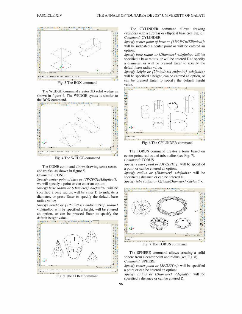
The CYLINDER command allows drawing
cylinders with a circular or elliptical base (see Fig. 6).
Command: CYLINDER
Specify center point of base or [3P/2P/Ttr/Elliptical]:
will be indicated a center point or will be entered an
option;
Specify base radius or [Diameter] <default>: will be
specified a base radius, or will be entered D to specify
a diameter, or will be pressed Enter to specify the
default base radius value;
Specify height or [2Point/Axis endpoint] <default>:
will be specified a height, can be entered an option, or
can be pressed Enter to specify the default height
value.
Fig. 6 The CYLINDER command
The TORUS command creates a torus based on
center point, radius and tube radius (see Fig. 7).
Command: TORUS
Specify center point or [3P/2P/Ttr]: will be specified
a point or can be entered an option;
Specify radius or [Diameter] <default>: will be
specified a distance or can be entered D;
Specify tube radius or [2Point/Diameter] <default>:
Fig. 7 The TORUS command
The SPHERE command allows creating a solid
sphere from a center point and radius (see Fig. 8).
Command: SPHERE
Specify center point or [3P/2P/Ttr]: will be specified
a point or can be entered an option;
Specify radius or [Diameter] <default>: will be
specified a distance or can be entered D.
THE ANNALS OF “DUNAREA DE JOS” UNIVERSITY OF GALATI FASCICLE XIV
97
Fig. 8 The SPHERE command
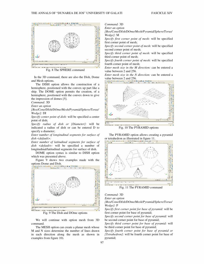
In the 3D command, there are also the Dish, Dome
and Mesh options.
The DISH option allows the construction of a
hemisphere, positioned with the convex up part like a
ship. The DOME option permits the creation, of a
hemisphere, positioned with the convex down to give
the impression of domes [5].
Command: 3D
Enter an option
[Box/Cone/DIsh/DOme/Mesh/Pyramid/Sphere/Torus/
Wedge]: DI
Specify center point of dish: will be specified a center
point of dish;
Specify radius of dish or [Diameter]: will be
indicated a radius of dish or can be entered D to
specify a diameter;
Enter number of longitudinal segments for surface of
dish <default>:
Enter number of latitudinal segments for surface of
dish <default>: will be specified a number of
longitudinal/latitudinal segments for surface of dish.
DOME option syntax is similar to DISH option
which was presented above.
Figure 9 shows two examples made with the
options Dome and Dish.
Fig. 9 The Dish and DOme options
We will continue with option mesh from 3D
command.
The MESH option can create a planar mesh whose
M and N sizes determine the number of lines drawn
in each direction along the mesh as shown in
examples from figure 10).
Command: 3D
Enter an option
[Box/Cone/DIsh/DOme/Mesh/Pyramid/Sphere/Torus/
Wedge]: M
Specify first corner point of mesh: will be specified
first corner point of mesh;
Specify second corner point of mesh: will be specified
second corner point of mesh;
Specify third corner point of mesh: will be specified
third corner point of mesh;
Specify fourth corner point of mesh: will be specified
fourth corner point of mesh;
Enter mesh size in the M direction: can be entered a
value between 2 and 256.
Enter mesh size in the N direction: can be entered a
value between 2 and 256.
Fig. 10 The PYRAMID options
The PYRAMID option allows creating a pyramid
or tetrahedron as illustrated in figure 11.
Fig. 11 The PYRAMID command
Command: 3D
Enter an option
[Box/Cone/DIsh/DOme/Mesh/Pyramid/Sphere/Torus/
Wedge]: P
Specify first corner point for base of pyramid: will be
first corner point for base of pyramid;
Specify second corner point for base of pyramid: will
be second corner point for base of pyramid;
Specify third corner point for base of pyramid: will
be third corner point for base of pyramid;
Specify fourth corner point for base of pyramid or
[Tetrahedron]: will be fourth corner point for base of
pyramid;

FASCICLE XIV THE ANNALS OF “DUNAREA DE JOS” UNIVERSITY OF GALATI
98
Specify apex point of pyramid or [Ridge/Top]: will be
specified the location for the type of pyramid’s top:
an apex, ridge, or a top.
The HELIX command can be found in Modeling
bar and creates a 2D or 3D spiral as shown in
examples from figure 12.
Command: HELIX
Number of turns =3 (default) Twist=CCW (default)
Specify center point of base: will be indicated a center
point of base;
Specify base radius or [Diameter] <1.000>: will be
specified a base radius, can be entered D to specify
the diameter, or can be pressed ENTER to specify the
default base radius value;
Specify top radius or [Diameter] <1.000>: will be
specified a top radius, can be entered D to specify the
diameter, or can be pressed ENTER to specify the
default top radius value;
Specify helix height or [Axis endpoint/Turns/turn
Height/tWist] <1.0000>: will be specified a helix
height or can be entered an option.
Fig. 12 The HELIX command
The PLANAR SURFACE command can be found
in Modeling bar and creates a planar surface as shown
in examples from figure 13.
Command: PLANESURF
Specify first corner or [Object] <Object>: will be
specified the first point for the planar surface;
Specify other corner: will be specified other corner
for the planar surface.
Fig. 12 The PLANAR SURFACE command
The SURFU and SURFV system variables control
the number of lines displayed on the surface.
The ISOLINES variable specifies the number of
contour lines on objects surface. This number can be
valid only when there are whole numbers from 0 to
2047.
In figure 13 are presented some primitive shapes
mentioned in this paper. In this case, we wanted to
realize a more realistic image, applying the
REALISTIC VISUAL STYLE command that is
found in the Visual Styles toolbar.
Fig. 13 The primitive shapes with the REALISTIC
VISUAL STYLE command
4. Conclusions The AutoCAD is a power also graphics program
that helps users to create simple or complex shapes in
bi-dimensional or three-dimensional space [2].
This paper presents some examples concerning
basic primitives using 3D command in AutoCAD
software. Of these we mentioned: Box, Cone,
Cylinder, Sphere, Dish, Dome, Torus, Pyramid,
Wedge and Mesh [2, 4]. This paper was also
concerned with three commands that we can find in
the Modeling toolbar called: Polysolid, Helix and
Planar Surface. So, a solid object is easier to construct
and will be the entire volume of an object.
References
[1] Goanţă A. M. Complex system of modern informatics methods
for teaching graphics disciplines from tehnical field , International
Conference on Engineering Graphics and Design, Series Applied
Mathematics and Mechanics 52, Vol.Ia, ISSN 1221-5872, pp.643-
646, Technical University of Cluj-Napoca, Acta Technica
Napocensis, 12-13 June 2009. [2] Haraga G. Applications of CAD systems, ICEGD 2009 -
International Conference on Engineering Graphics and Design,
Series Applied Mathematics and Mechanics 52, Vol.Ia, ISSN 1221-5872, pp.291-294, Technical University of Cluj-Napoca, Acta
Technica Napocensis, 12-13 June 2009.
[3] Ion, E.E. , Haraga, G. Ioniţă E., Elemente de grafică
computerizată, Ed. MATRIX ROM, ISBN 973-685-645-3,
Bucuresti, 2003.
[4] Simion, I., AutoCAD 2008 pentru ingineri, Ed. Teora, ISBN
978 973-20-1135-5, Bucuresti, 2008.
[5] http://docs.autodesk.com