
Creating Dialog Based Applications with MFC...
16
Creating Dialog Based Applications with MFC 7 By Jason Pursell, University of Washington, Bothell (2000-2003) [email protected] Introduction This tutorial demonstrates how to create a simple dialog based application with MFC 7 and Visual Studio .NET. Note: I originally created this tutorial to aid my classmates in using Visual Studio .NET and MFC 7 during the 2002 school year when many students were still using Visual Studio 6 and MFC 6. It should also be noted that this tutorial is based on another one from CodeProject.com, A Beginners Guide to Dialog Based Applications – Part One , by Dr. Asad Altimeemy. Please check that one out if you are interested in using Visual Studio 6 and MFC 6, because I will focus solely on MFC 7 in this tutorial. The Visual Studio .NET IDE Visual Studio .NET allows multiple programming languages to share the Integrated Development Environment (IDE), so there are new parts to the IDE that are common to all the languages, and some familiar parts are gone or replaced (see Figure 1 and Table 1). For the purposes of this tutorial, I will focus only on the parts related to MFC. 3,4,5 2 1 6 Figure 1. Some parts of the IDE that are new and/or improved. 1
-
Upload
vuongduong -
Category
Documents
-
view
230 -
download
0
Transcript of Creating Dialog Based Applications with MFC...

Creating Dialog Based Applications with MFC 7 By Jason Pursell, University of Washington, Bothell (2000-2003) [email protected] Introduction This tutorial demonstrates how to create a simple dialog based application with MFC 7 and Visual Studio .NET.
Note: I originally created this tutorial to aid my classmates in using Visual Studio .NET and MFC 7 during the 2002 school year when many students were still using Visual Studio 6 and MFC 6. It should also be noted that this tutorial is based on another one from CodeProject.com, A Beginners Guide to Dialog Based Applications – Part One, by Dr. Asad Altimeemy. Please check that one out if you are interested in using Visual Studio 6 and MFC 6, because I will focus solely on MFC 7 in this tutorial.
The Visual Studio .NET IDE Visual Studio .NET allows multiple programming languages to share the Integrated Development Environment (IDE), so there are new parts to the IDE that are common to all the languages, and some familiar parts are gone or replaced (see Figure 1 and Table 1). For the purposes of this tutorial, I will focus only on the parts related to MFC.
3,4,5
2 1
6
Figure 1. Some parts of the IDE that are new and/or improved.
1

Solution Explorer Class View Resource View IDE Component Description
1. Toolbox – Displays a variety of items for use in Visual Studio projects such as controls, components, and code/text fragments.
2. Dialog Editor (MFC) – This is where you create or edit dialog box resources. Beware – this is not Windows Forms!
3. Solution Explorer – Provides you with an organized view of your projects and their files as well as ready access to the commands that pertain to them.
4. Class View – Displays a programmatic view of symbols in your code, for example, namespaces, classes, methods, and functions.
5. Resource View – Displays the resource files included in your projects.
6. Properties Window – Use this window to view and change the design-time properties and events of selected objects that are located in editors and designers.
Table 1. IDE components. The location of the each of the views (or windows) is totally dependent upon the profile you are using. The profile can be set from the Start Page under My Profile. The Start Page usually shows when you start Visual Studio .NET. The properties window is new and its buttons are important (Figure 2). The first two on the left just determine how the items are displayed in the list. The next three determine what is displayed: Properties, Control Events, Messages, or Overrides (in that order). Control Events, Messages, and Overrides are only available when certain things are selected. For example, Figure 2 is what is available when CDialog1Dlg is selected in the Class View (as in the picture of the Class View at the top of the page); however, the Overrides icon is only shown when a class is selected.
2

Show Properties
Show Control Events
Show Messages
Show Overrides
Alphabetize Properties
Categorize Properties
Figure 2. Buttons of the properties window.
3
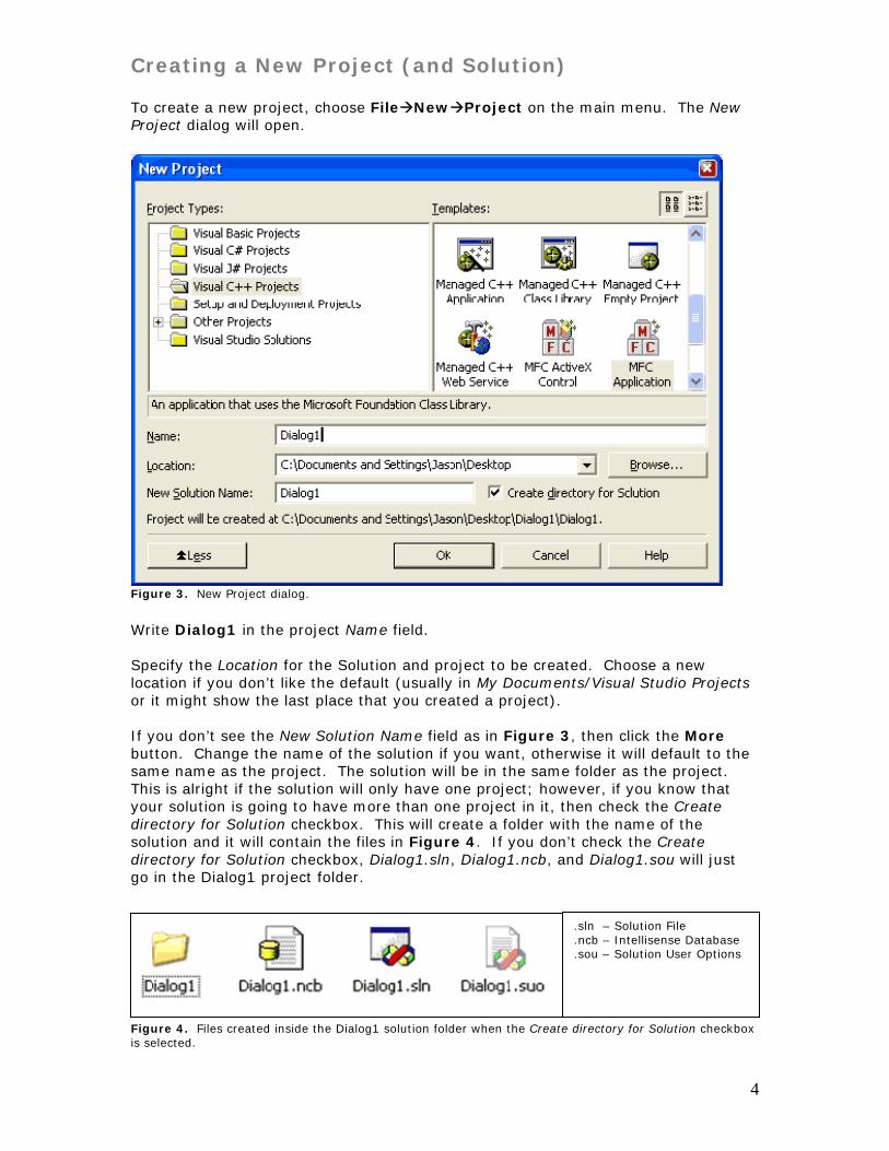
Creating a New Project (and Solution) To create a new project, choose File New Project on the main menu. The New Project dialog will open.
Figure 3. New Project dialog.
Write Dialog1 in the project Name field. Specify the Location for the Solution and project to be created. Choose a new location if you don’t like the default (usually in My Documents/Visual Studio Projects or it might show the last place that you created a project). If you don’t see the New Solution Name field as in Figure 3, then click the More button. Change the name of the solution if you want, otherwise it will default to the same name as the project. The solution will be in the same folder as the project. This is alright if the solution will only have one project; however, if you know that your solution is going to have more than one project in it, then check the Create directory for Solution checkbox. This will create a folder with the name of the solution and it will contain the files in Figure 4. If you don’t check the Create directory for Solution checkbox, Dialog1.sln, Dialog1.ncb, and Dialog1.sou will just go in the Dialog1 project folder.
.sln – Solution File
.ncb – Intellisense Database
.sou – Solution User Options
Figure 4. Files created inside the Dialog1 solution folder when the Create directory for Solution checkbox is selected.
4

Note: The Dialog1.sln file is somewhat analogous to the DSW file in Visual C++ 6 (i.e. this is what you double-click to load the entire solution in the future).
Click the OK button when ready. The MFC Application wizard will start. On the menu, choose Application Type (circled in red in Figure 5).
Figure 5. Page one of the wizard.
Figure 6. Application Type page of the wizard. Choose the options that are circled in red in Figure 6. Click the Finish button. Note: Feel free to look at the other pages; however, for this tutorial we will accept the defaults.
5

Designing the Dialog Note: If the Dialog Editor is not showing, open the Resource View (Ctrl+Shift+E) and expand the Dialog folder, then double-click IDD_DIALOG1_DIALOG.
Figure 7. The Dialog Editor in action.
2. Selection Handle. This can be dragged to change the size of the dialog. The width and height are indicated in are below circled in blue.
1. Click the title bar to select the Dialog itself.
HINT: Investigate the blue line after the tutorial. Try to figure out what it is used for. It can be useful.
Click on the text TODO: Place dialog controls here, then press Delete. Next, as in Figure 7 above, select the dialog by clicking on the edge of the title bar. The dialog will now have sizing handles on its sides and corners. These are used to resize the dialog. The width and height of the dialog is indicated at the bottom-right of the IDE and is circled in blue in the diagram above. Left-click and Drag the bottom-right selection handle up and to the left until the size of the dialog is at a width and height of 230 x 126, then release the mouse button. Note that there is nothing special about these dimensions. They are just the numbers that allowed me to fit the controls on the dialog in a “nice” manner. ☺ Since we don’t need the Cancel button in our application, select it by left-clicking it once. The button is selected when sizing handles surround it. Press Delete. Next we need to change some of the properties of the OK button. Select the OK button by left-clicking it once. Figure 8 shows how the Properties window reflects the properties of the button when it is selected.
Note: Depending on your choice of IDE setup, the Properties window might be on the left or right. If it is not showing, then choose View Properties Window from the main menu or press F4 on the keyboard.
6

Figure 8. Properties of the OK button. Change the Caption of the button by typing Close in the value field of the Caption property (Figure 9 on the next page).
Type in here!
Figure 9. Changing the Caption property of the button. Now the button on the dialog reads “Close”.
7

Adding Controls Next, you will add some new controls to the dialog. Our example will have nine controls in total. These controls are located in the Toolbox window. Using these controls, we will create a dialog similar to the one in Figure 10 below.
Note: Depending on your choice of IDE setup, the Toolbox window might be hidden. By default it is on the left side of the IDE. If it is not showing, then choose View Toolbox from the main menu or use the Ctrl+Alt+X keyboard shortcut.
Figure 10. Example layout of the Dialog1 dialog. To select a control from the toolbox, left-click it once to select it and then place it on the dialog by left-clicking in the general area of where you want it positioned. You can also just drag a control from the Toolbox to the dialog. Try both ways to see which you prefer. As an example, the first control we add to the dialog will be a new button.
Before
After
8

Next we will change a couple of the properties of the new button. First, select the button on the dialog. Next, in the Properties window, change the following properties of the button:
9
Property Value ID IDC_ADD Caption Add
The ID property determines how the each control is identified by MFC in code. Every control must have an ID. You will see how this works later in the tutorial.
Next, the Caption property is what is displayed on the control and is what the User will see when using the application. Not all controls have a Caption property.
Use Table 2 on the next page as a guide to add the remaining controls to the dialog. As you add each control to the dialog, change its properties to the values shown in the table just as you did for the Add button. Again, we want to build a dialog similar to Figure 10 above.

10
Control Property Value Static Caption Title Static Caption First Name Static Caption Last Name Edit ID IDC_FIRSTNAME Edit ID IDC_LASTNAME
ID IDC_TITLE Data Mr.;Mrs.;Miss;Ms.;Dr. Combo Box Type Drop List
List Box ID IDC_NAMELIST Table 2. The controls and their properties that we want to change. Please see Figure 11 for an example of the property settings for the combo-box. Here is an example of the properties of the combo-box control that we added. The properties we will change are highlighted in red.
Figure 11. The properties of the IDC_TITLE combo box control. Next, we need to specify the length of the combo-box drop down list. Position the mouse over the drop-down arrow of the combo-box and left-click once. Use the blue resizing handle to adjust the length, similar to Figure 12. Click the drop down arrow on the combo-box again to toggle back to the normal control resizing mode.
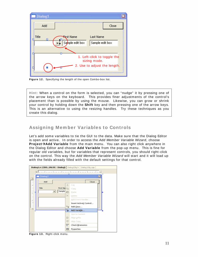
2. Use to adjust the length.
1. Left-click to toggle the sizing mode.
Figure 12. Specifying the length of the open Combo-box list.
Hint: When a control on the form is selected, you can “nudge” it by pressing one of the arrow keys on the keyboard. This provides finer adjustments of the control’s placement than is possible by using the mouse. Likewise, you can grow or shrink your control by holding down the Shift key and then pressing one of the arrow keys. This is an alternative to using the resizing handles. Try these techniques as you create this dialog.
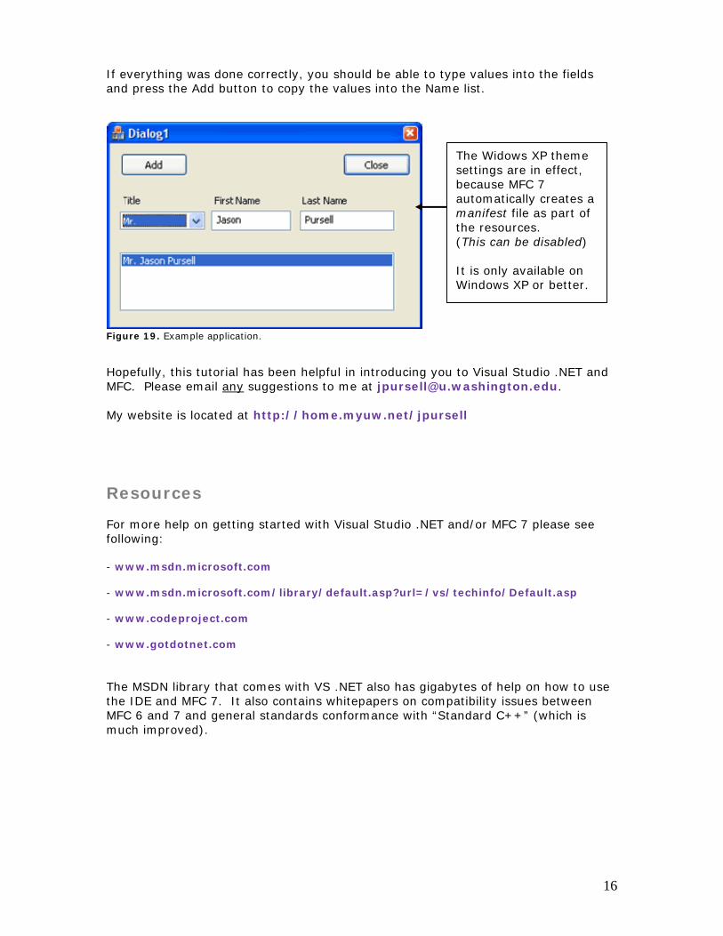
Assigning Member Variables to Controls Let’s add some variables to tie the GUI to the data. Make sure that the Dialog Editor is open and active. In order to access the Add Member Variable Wizard, choose Project Add Variable from the main menu. You can also right click anywhere in the Dialog Editor and choose Add Variable from the pop-up menu. This is fine for regular old variables, but for variables that represent controls, you should right-click on the control. This way the Add Member Variable Wizard will start and it will load up with the fields already filled with the default settings for that control.
Figure 13. Right-click menu.
11

We will work with the First Name Edit control first. In the Dialog Editor, right-click the First Name Edit control. From the pop-up menu, choose Add Variable. As in Figure 14, make sure the following settings are present before pressing the Finish button: Control variable checked, Control ID to IDC_FIRSTNAME, Access to private, Category to Value, Variable to CString, Control type to EDIT, and Variable name to m_strFirstName.
Figure 14. The Add Member Variable Wizard for the First Name edit control. Use table 3 as a guide to enter the other variables. Control ID Access Variable
type Variable Name Category Control
type Control variable
IDC_LASTNAME private CString m_strLastName Value EDIT yes
IDC_TITLE private CString m_strTitle Value COMBOBOX yes
IDC_NAMELIST private CString m_strFullName Value LISTBOX Yes
IDC_NAMELIST Private CListbox m_NameList Control LISTBOX yes
Table 3. The remaining variables that need to be added via the Add Variable Wizard
Remember: Right-click on the control to add a variable. There are other ways, but this is the easiest for you, because it “pre-fills” some of the fields.
Note: IDC_NAMELIST has two variables for it. The CString variable has a category of Value and the CListbox variable has a category of Control.
12

Adding Message Handlers for the Controls There is more than one way to add an event handler. I will show a couple of ways here. Each has their pros and cons. Both of the methods refer to the Add button.
Note Read over both methods first and then decide which one you want to use.
Method One Right-click on the control that you are interested in (the Add button in this case), then choose Add Event Handler from the pop-up menu (see Figure 15). This will bring up the Event Handler Wizard. There you can fill in the information. For the Add button the Message Type is BN_CLICKED, the Class list is CDialog1Dlg, and the Function handler name is OnAdd.
Figure 15. Accessing the Event Handler Wizard from right-clicking on controls.
13

Click the Add and Edit button when done. This will take you to the newly added method where you can begin adding your own code. Method Two The second method is done through the Properties window and is very convenient. First, left-click on a control to select it. The Properties window will change to represent the control. Click the Control Events button. Next, click on the BN_CLICKED control event. If you click the down arrow, you will see Figure 16. We want to use our own name, so instead, just type in the field as in Figure 17. As soon as you press Enter, the main window will change to code view and the cursor will be positioned in the newly created method waiting for you to add some of your own code. The code that you will add is on the next page.
Figure 16. The default event handler function name provided by MFC
WolaT
Figure 17. Accessing the Add Event Handler through the Properties w Now that you’ve read through both methods, follow onethe Add button.
Control Events Button
Don’t choose this unless you want the function to have the default name.
.
e want to use our wn name, so just eft-click once in here nd type: OnAdd hen press Enter.
indow.
to add an event handler for
14

Add the following code to the OnAdd function: void CDialog1Dlg::OnAdd() { // TODO: Add your control notification handler code here CString strTitle; int nIndex; UpdateData(); // DDX - Transfer data from the controls to variables //get the currently selected text nIndex = GetDlgItemText(IDC_TITLE, strTitle); m_strFullName = strTitle + " " + m_strFirstName + " " + m_strLastName; m_NameList.AddString(m_strFullName); UpdateData(FALSE); // DDX - Transfer data from variables to controls }
Building and Running the Program To run, just press CTRL+F5 or Debug Start Without Debugging. Choose “Yes” when asked to rebuild the files. Hint Using Start Without Debugging is much faster than Starting (with
debugging). This is especially true when compiling C# or VB.NET programs in Visual Studio .NET. The debugger is very powerful, though, so when you need it just choose Start (or F5).
Figure 18. Debug menu.
15
If everything was done correctly, you should be able to type values into the fields and press the Add button to copy the values into the Name list.
The Widows XP theme settings are in effect, because MFC 7 automatically creates a manifest file as part of the resources. (This can be disabled) It is only available on Windows XP or better.
Figure 19. Example application. Hopefully, this tutorial has been helpful in introducing you to Visual Studio .NET and MFC. Please email any suggestions to me at [email protected]. My website is located at http://home.myuw.net/jpursell
Resources
For more help on getting started with Visual Studio .NET and/or MFC 7 please see following: - www.msdn.microsoft.com - www.msdn.microsoft.com/library/default.asp?url=/vs/techinfo/Default.asp - www.codeproject.com - www.gotdotnet.com The MSDN library that comes with VS .NET also has gigabytes of help on how to use the IDE and MFC 7. It also contains whitepapers on compatibility issues between MFC 6 and 7 and general standards conformance with “Standard C++” (which is much improved).
16


![Reference Guide MFC-J6947DW MFC-J6945DW MFC-J6545DW · MFC-J6545DW MFC-J6945DW MFC-J6947DW ... [Message from Brother] and [Firmware Auto Check] are set to [On]. (Internet connection](https://static.fdocuments.in/doc/165x107/5fe53fa6fe9ed37e6d21c94e/reference-guide-mfc-j6947dw-mfc-j6945dw-mfc-j6545dw-mfc-j6545dw-mfc-j6945dw-mfc-j6947dw.jpg)


