Creating Butterflies in the Core – A Network …...Creating Butterflies in the Core – A...
12
Creating Butterflies in the Core – A Network Coding Extension for MPLS/RSVP-TE (Work in Progress) Thorsten Biermann, Arne Schwabe, and Holger Karl University of Paderborn, Research Group Computer Networks, Pohlweg 47-49, 33098 Paderborn, Germany {thorsten.biermann,arne.schwabe,holger.karl}@upb.de Abstract. Network Coding exploits network resources more efficiently than plain routing. Specifically, it reduces packet delays and packet loss rates. Such advantages are especially useful in core networks where many different users can benefit from this at once. Hence, network coding should be transparently integrated in technologies suitable for core net- works. We present an extension for MPLS and RSVP-TE which can instantiate network-coded paths in core networks. The feasibility of this approach is demonstrated in a proof-of-concept simulation. Keywords: Network coding, Signaling, Core, MPLS, RSVP-TE. 1 Introduction The technique of Network Coding (NC), as first introduced by Ahlswede et al., has become a vivid area in current networking research. Instead of only forwarding packets, NC permits nodes on the packets’ route to process the data, i.e., to modify and mix up their content. These transformations are inverted at a decoder again to deliver the original content to the destination. Depending on where which transformations happen, various benefits can be achieved. There is a variety of applications where users can benefit from NC. In this paper, we concentrate on NC to use available network resources more efficiently than with plain routing. In particular, we look at core networks where multiple flows share physical links. In such scenarios, links are usually redundantly de- ployed to deal with link failures or temporary overload situations. Affected flows are switched from the broken or overloaded link to alternative links. An example for such a scenario is depicted in Fig. 1(a) and 1(b) where the link R1→R2 gets congested due to a failure or a load peak. As soon as the congestion is detected, Flow 2 (blue/dotted) is redirected to the alternative route on the right side (S2→D1→R2). Although all links are The research leading to these results has received funding from the European Com- munity’s Seventh Framework Programme (FP7/2007-2013) under grant agreement n ◦ 216041. L. Fratta et al. (Eds.): NETWORKING 2009, LNCS 5550, pp. 883–894, 2009. c IFIP International Federation for Information Processing 2009
Transcript of Creating Butterflies in the Core – A Network …...Creating Butterflies in the Core – A...

Creating Butterflies in the Core – A Network
Coding Extension for MPLS/RSVP-TE�
(Work in Progress)
Thorsten Biermann, Arne Schwabe, and Holger Karl
University of Paderborn, Research Group Computer Networks,Pohlweg 47-49, 33098 Paderborn, Germany
{thorsten.biermann,arne.schwabe,holger.karl}@upb.de
Abstract. Network Coding exploits network resources more efficientlythan plain routing. Specifically, it reduces packet delays and packet lossrates. Such advantages are especially useful in core networks where manydifferent users can benefit from this at once. Hence, network codingshould be transparently integrated in technologies suitable for core net-works. We present an extension for MPLS and RSVP-TE which caninstantiate network-coded paths in core networks. The feasibility of thisapproach is demonstrated in a proof-of-concept simulation.
Keywords: Network coding, Signaling, Core, MPLS, RSVP-TE.
1 Introduction
The technique of Network Coding (NC), as first introduced by Ahlswede etal., has become a vivid area in current networking research. Instead of onlyforwarding packets, NC permits nodes on the packets’ route to process the data,i.e., to modify and mix up their content. These transformations are inverted ata decoder again to deliver the original content to the destination. Depending onwhere which transformations happen, various benefits can be achieved.
There is a variety of applications where users can benefit from NC. In thispaper, we concentrate on NC to use available network resources more efficientlythan with plain routing. In particular, we look at core networks where multipleflows share physical links. In such scenarios, links are usually redundantly de-ployed to deal with link failures or temporary overload situations. Affected flowsare switched from the broken or overloaded link to alternative links. An examplefor such a scenario is depicted in Fig. 1(a) and 1(b) where the link R1→R2 getscongested due to a failure or a load peak.
As soon as the congestion is detected, Flow 2 (blue/dotted) is redirected tothe alternative route on the right side (S2→D1→R2). Although all links are
� The research leading to these results has received funding from the European Com-munity’s Seventh Framework Programme (FP7/2007-2013) under grant agreementn◦ 216041.
L. Fratta et al. (Eds.): NETWORKING 2009, LNCS 5550, pp. 883–894, 2009.c© IFIP International Federation for Information Processing 2009

884 T. Biermann, A. Schwabe, and H. Karl
1
1
1
1 1
S1 S2
R2
R1
D2 D1
(a) Enough capacityis available. Packets ofboth flows are trans-ported using classicforwarding. The over-all latency is 3.
1 1
1
1
1
d
S1 S2
R2
R1
D2 D1
(b) Overload onR1→R2 forces theblue/dotted flow tobe redirected via analternative route. Itslatency raises to d+2.
1 1
1 1
dd 1
S1 S2
R2
R1
D2 D1
(c) Alternatively, NCis applied: Encodingis done at node R1;decoding at D1 andD2. Latency remainsat max(d, 3).
Fig. 1. Comparison of classic transmission via packet forwarding and NC-enabledtransmission of two data flows. The numbers next to links denote their latencies. Incontrast to routing, NC permits load shifting from link R1→R2 to lateral links whileretaining low latency.
now able to deal with the incoming load, depending on the alternative links’properties, the rerouted flow might suffer from noticeably higher delay.
To overcome this drawback, linear NC can be applied. This technique regardspackets as vectors and allows a node to apply a linear transformation to thembefore they are forwarded. Linear NC achieves optimal throughput for multicasttransmission, i.e., the maximum flow from the source to each receiving node. Aspecial case of such linear transformations is calculating the XOR value of twopackets. In our scenario, instead of completely redirecting one of the flows, bothof them are jointly encoded at R1 by calculating the XOR of each packet pairof the flows. This reduces load on the bottleneck link and maintains low delayfor both flows. Decoding is done at the destinations, as shown in Fig. 1(c).
The techniques and benefits of network coding have been widely explored [1],but the control problem – when and where to turn it on and how to signalthis – has only been addressed in wireless contexts [2,3] or on the applicationlayer [4]. Specifically, we are not aware of approaches trying to integrate NCinto wired systems on the link or network layer. Especially, controlling NC fortraffic flows in core networks, where many users benefit at once, is not possibleso far. To achieve this, we present a signaling protocol in Sec. 3 and 4 thattriggers and controls the instantiation of network-coded paths in networks usingMultiprotocol Label Switching (MPLS), as a typical example of a core networktechnology. Our protocol is independent of the algorithm used for detecting NCpossibilities, i.e., finding suitable subtopologies [5], as well as of the algorithmthat decides when to actually activate coding. Both decisions are made on topof our signaling protocol. The feasibility is demonstrated in a proof-of-conceptsimulation in Sec. 5. Sec. 2 briefly summarizes relevant MPLS background.

Creating Butterflies in the Core 885
2 Background
Data transport in core networks is often realized with label switching. Instead ofevaluating hierarchical IP addresses, simple flat labels are prepended to packets.A switch processes incoming packets solely based on their label, i.e., all packetswith the same label are treated equally.
Label switching requires two components: a data transport service which ac-tually transports the data packets based on their labels and a label distributionprotocol which sets up the Label Switched Paths (LSPs), i.e., distributes labelsto be used among Label Switch Routers (LSRs). This determines the actualforwarding behavior. As MPLS [6] is a practically highly relevant transport ser-vice for label switching, we will focus on extending it by NC; in principle, thetechnique should also be applicable to other label switching transport services.
Resource Reservation Protocol – Traffic Engineering (RSVP-TE) [7] is one ofseveral label distribution protocols that can be used with MPLS. It has beenextended multiple times to support emerging networking technologies and con-solidates many aspects of traffic engineering in a single protocol. Besides thewide adoption, we have chosen this protocol as base for our extension becausethere is already a Point-to-Multipoint (P2MP) extension available [8] which isnecessary for applying XOR NC in a butterfly topology.
3 Extending MPLS to Support NC
To perform XOR NC in a butterfly, three issues have to be solved: packets mustbe encoded (at node R1 in Fig. 1(c)), the uncoded packets must be sent to decod-ing points (from S1/S2 to D2/D1), and the right encoded and uncoded packetsmust be matched for the decoding operation (at D1/D2). When implementingthese additional functions, the following requirements have to be met:
– Using NC must not disrupt normal label switching operation.– Modifying nodes not directly involved in NC operations, i.e., which only
forward network-coded packets, is not acceptable.
To achieve this in MPLS, two modifications are required. First, LSRs which areresponsible for en-/decoding need to be extended to support these operationsand, second, one LSR passing the flow to be encoded must be able to add packetsequence numbers as packets must be uniquely identifiable. Hence, in contrast totraditional label switching where all LSRs are equal and perform the same oper-ations (packet forwarding based on labels), NC requires to distinguish betweendifferent roles that LSRs may adopt:
– Forwarding LSRs perform traditional store-and-forward operations requiredfor ordinary packet forwarding. This also encompasses cloning of flows formulticasting. The payload of forwarded packets is unchanged.
– Numbering LSRs add packet sequence numbers to MPLS flows. The packets’payload is not altered either.

886 T. Biermann, A. Schwabe, and H. Karl
– Encoding LSRs apply XOR coding to packets of two incoming flows. Theresult is one encoded output flow.
– Decoding LSRs receive one encoded and a corresponding plain flow. Afterdecoding, the resulting decoded packets are forwarded.
Required modifications for implementing the different LSRs are described in thefollowing two subsections. Setting up paths is mostly a problem for the signalingprotocol and described separately in Sec. 4.
3.1 Encoding and Decoding
In MPLS, an LSR determines how to treat an incoming packet solely based onits label; the concrete action is determined by a Next Hop Label ForwardingEntry (NHLFE). NHLFEs are basically table entries which map an incominglabel/interface combination to corresponding next-hop information (outgoinginterface and next-hop address) and label manipulation instructions like labelpush, pop, or swap operations.
To support XOR NC, NHLFEs must be extended to not only support simpleforwarding of packets but to also indicate to the LSR that two incoming flowsshall be combined to one single outgoing flow. This is done by feeding packets ofan incoming flow into an encoder. The partner flow for encoding is selected bya second NHLFE which feeds another flow into the same encoder instance. Thisencoder contains all functionality required for the actual encoding operation likebuffering, XOR calculation, etc. This modification is sufficient to implement anXOR Encoding LSR, as well as the corresponding Decoding LSR.
3.2 Packet Sequence Numbers
To be able to successfully decode packets at destination LSRs, these nodes needto know which packets from which flow were used for encoding (e.g., trying todecode (a XOR b) from flows A and B with a packet b′ from flow B obviously giveswrong results). Hence, packets forming an MPLS flow which is involved in anycoding operation must carry information that allows their unique identification.The simplest way to achieve this is by adding sequence numbers to packets.
As MPLS flows usually transport an aggregate of many different flows, it isimpossible to reuse sequence numbers of upper layers for this; they have to beexplicitly generated for a given MPLS flow. This is done by Numbering LSRswith a special NHLFE. Such coding-related sequence numbers are not requiredover the whole packet lifetime. It is sufficient to add them before the flow ismulticasted. E.g., in the scenario depicted in Fig. 1(c), this is done by the LSRsS1 and S2 at the latest. At the Encoding LSR (R1), both flows are combinedand, hence, each packet of the encoded flow must carry two sequence numbers.
Extending the MPLS header to transport the additional packet sequence num-ber is not feasible as this breaks compatibility to standard MPLS implementa-tions. Normal LSRs would not be able to forward packets already numbered forNC later on, but this is an obvious deployment requirement. Therefore, we use

Creating Butterflies in the Core 887
0 23 2420 32
Label Exp S TTL
L3MPLS MPLS
Label (SeqNum) Exp S TTL
64
Normal Forwarding Header Sequence Number Header
Fig. 2. MPLS label stacking is exploited to transport packet sequence numbers. Thelabel field of the inner header contains the packet’s sequence number.
the label stacking feature of MPLS to push an additional sequence number labelon the stack, transporting the sequence numbers within the 20bit label field.Fig. 2 shows a sample stack transporting a single packet sequence number.
Sequence numbers also allow us to treat boundary cases. For example, it couldhappen that at the Encoding LSR, a packet arrives and, even after waiting sometime, no packet from the partner flow is available for joint coding. One optionwould be to stall such a packet until a partner packet for encoding arrives; analternative is to send this packet uncoded (to avoid blocking buffers) and toindicate from which flow a packet is missing by an empty sequence number.
4 Extending RSVP-TE to Signal NC-Enabled Paths
The modified MPLS system can realize NC operations within the network. Whatis still missing is a mechanism to propagate forwarding and de-/coding configu-rations to involved nodes to actually turn on NC. To do so, the label distributionprotocol has to be extended as well. For the design of the RSVP-TE NC protocolextension we must meet the following requirements:
– Using NC functionality must not disrupt normal RSVP-TE operation.– Switching an LSP from normal to coded operation must be possible without
disturbing the ongoing transmission.– Assured QoS constraints must not be violated when using NC, i.e., RSVP-
TE must still be able to manage reservations and guarantee them.– Although the extension was designed with XOR NC in butterfly-like topolo-
gies in mind, it is kept as flexible as possible to easily permit other codingtechniques and topologies as well.
Fulfilling these requirements guarantees a seamless integration of NC LSPs intoa running network. The actual decision if and where NC is applied within thenetwork and which pairs of flows should be coded together is orthogonal to thesignaling problem addressed in this paper. Our signaling scheme supports anykind of decision algorithm on top. The decision can even be made independentlyfrom the nodes forming a coded path. The only limitation is that the decisionmust be communicated to a node on the path to start the signaling process.
Based on the presented assumptions, the next sections describe how a NCLSP is actually set up (Sec. 4.1) and teared down again (Sec. 4.2).

888 T. Biermann, A. Schwabe, and H. Karl
SENDER_TEMPLATEP1’
Coding−Group Originator ID = R1Coding−Group ID = 123
SENDER_TEMPLATEP1
Coding−Group Originator ID = 0Coding−Group ID = 0
CODING_PARAMETERSCodingType = 1Flags = 01
CODING_POINTSR1
DECODING_POINTSD2
P1
P1’
P1’P1
S1 S2
R2
R1
D2 D1
(a) Path 1 is set up first.PATH message P1 is mod-ified at R1. The resultingmessage is called P1’.
SENDER_TEMPLATEP2
Coding−Group Originator ID = 0Coding−Group ID = 0
CodingType = 1CODING_PARAMETERS
Flags = 01CODING_POINTSR1
DECODING_POINTSD1
SENDER_TEMPLATEP2’
Coding−Group Originator ID = R1Coding−Group ID = 123
CODING_PARAMETERSFlags = 11
P1’’CODING_PARAMETERSFlags = 11
P2
P2’P1’’
P1’’P2’
P2
S1 S2
R2
R1
D2 D1
(b) Path 2 is also set up.Besides P2 being modifiedto P2’ at R1, path 1 is alsorefreshed using P1”.
R2Coding partner listCODING_PARTNER = <flow1>,STACK_POSITION = 0;
R1’’Coding partner listCODING_PARTNER = <flow2>,STACK_POSITION = 1;
R1’’R2
R2
R2
R1’’
R1’’
S1 S2
R2
R1
D2 D1
(c) The setup of path 2and refreshing of path 1is acknowledged to thesources via RESV messages.
Fig. 3. Sample for joint setup of two network-coded LSPs. S1/S2 are ingress LSRs,R1 is the Encoding LSR, and D1/D2 are the egress LSRs which do the decoding.Red/dashed arrows denote signaling messages belonging to path 1; blue/dotted arrowsthe signaling of path 2. The first RESV reply for path 1 is omitted. The boxes denotethe signaling messages (only NC-relevant data which has changed is shown).
4.1 Setting Up Network-Coded Paths
RSVP-TE uses end-to-end semantics to set up paths by sending a PATH messagefrom the ingress to the egress LSR. It is acknowledged by a RESV message. Hence,the use of NC has to be signaled by the ingress LSRs of both flows to be encoded.
There are two possible constellations how network-coded LSPs can be set up.In the first and simpler case, both ingress LSRs are aware that their LSPs willbe used for NC. Hence, they are both initially set up with NC enabled. In thesecond case, one or both sources start without the knowledge that their LSP willbe used for NC later on. Hence, the paths are set up without NC enabled. Thismeans that the NC-unaware LSPs must be converted with RSVP-TE’s reroutingmechanisms [7, Sec. 4.6.4] afterwards. This procedure is not discussed here as itis identical to the standard behavior of RSVP-TE.

Creating Butterflies in the Core 889
Simultaneous Setup of Network-Coded Paths. In this scenario, bothingress LSRs S1 and S2 know at instantiation time that their LSPs will beencoded. This information can either be propagated automatically by the algo-rithm which decides when and where NC is applied, or can be given manually.
The setup process is clarified in Fig. 3, which illustrates important steps ofour signaling scheme. The LSPs start at the nodes S1/S2 and end at D1/D2.Path 1 (starting at S1) is set up first with initially no NC active. It is refreshedafter the creation of Path 2 to be jointly encoded. To transport the addition-ally required NC parameters, the PATH and RESV messages are extended. Thesemodifications will be described in detail later on. Note that at points where thepath is multicast, PATH messages are copied and sent along both subpaths, akinto the P2MP upon which we built.
The path setup starts at S1 by sending the first PATH message P1 to R1 andD2. After R1 added itself as Coding-Group Originator and assigned a newCoding-Group ID, the message P1’ is sent to R2 and finally to D1. As codingis not yet activated, D1 responds with a standard RESV message (not shown).Next, S2 also starts its path setup by sending P2. R1 receives P2 and detectsthe coding possibility with the first LSP based on the DECODING POINTS. Hence,coding is enabled in P2’ and path 1 is refreshed using a new PATH message P1”.
Signaling of label stack positions for particular sequence number labels is onlydone by the Decoding LSRs when coding is actually enabled. Fig. 3(c) showsthis signaling within the RESV message after encoding has been enabled by R1.
Modified PATH message. The intention of setting up an NC-enabled path issignaled by modifying its SENDER TEMPLATE object and by adding four additionalobjects to the PATH message. These changes are discussed in the following.
SENDER TEMPLATE. Two LSPs which shall be jointly encoded must be markedsuch that Numbering, Encoding, and Decoding LSRs know about this inten-tion. Therefore, two additional fields (Coding-Group Originator ID andCoding-Group ID) are added to the SENDER TEMPLATE object. Both are ini-tialized with zeros by the source LSR and will be filled by the Encoding LSR.Similar to the P2MP extension, the Originator ID specifies the ID of theEncoding LSR (usually its IP address), whereas the ID is assigned by theEncoding LSR for this particular encoding operation. In combination, bothIDs identify the group of LSPs which are jointly encoded on a global scope.
CODING PARTNERS. There are two ways of establishing encoded LSPs: explicitand automatic partner flow selection. For the explicit partner selection, thedesired partner flows are specified in the CODING PARTNERS object by a listof subobject pairs. Each pair consists of the partner flow’s SESSION andSENDER TEMPLATE object. This uniquely identifies LSPs for joint encoding.In case there is no CODING PARTNERS.object in the PATHmessage, an EncodingLSR may choose any LSPs for joint encoding. The LSR’s decision is signaledby adding a CODING PARTNERS object referencing the selected partner flow.
CODING PARAMETERS. This field is used to define the coding operation that isactually applied at the Encoding LSR (CodingType) and transports severalstatus flags concerning the setup procedure of the coded path (Flags).
890 T. Biermann, A. Schwabe, and H. Karl
The CodingType field carries a simple identifier of the coding technique thathas to be applied at Encoding LSRs. The meaning of these identifiers has tobe unique within a NC MPLS domain.As mentioned, the flags are used to signal important parameters during thepath setup. Their meaning usually differs for different coding techniques. Forthe butterfly NC we implemented the following flags:– 0x01 Sequence numbers active. The Numbering LSR sets this flag. This
will usually be the LSR where the path is multicasted. It is required tocheck whether encoding and decoding is possible and to prevent multipleNumbering LSRs.
– 0x02 Coding active. The Encoding LSR enables this flag when the en-coding operation is active. It is required to prevent multiple EncodingLSRs and to signal active encoding to potential Decoding LSRs to en-able buffering. Furthermore, intermediate LSRs, e.g., R2 in Fig. 3, re-act on two LSPs sharing the same Coding-Group Originator ID andCoding-Group ID which both have the active coding flag set. In thiscase both paths must be merged to multicast the encoded packets.
CODING POINTS. This object contains a list of LSRs which are permitted totake over the role of the Encoding LSR. LSRs listed in this object watch forexisting and future LSPs to enable the encoding operation whenever possible.The decision which flows are coded depends on the LSPs’ CODING PARTNERSobjects. The format is identical to the EXPLICIT ROUTE object in RSVP-TE.
DECODING POINTS. This object has the same format as the CODING POINTS ob-ject. It defines a list of LSRs which are able to decode data flows which havebeen jointly encoded with this flow, i.e., which will receive a plain copy ofthis flow. Each LSR which is contained in this list looks for other flows thatare jointly encoded to take the role of the Decoding LSR.
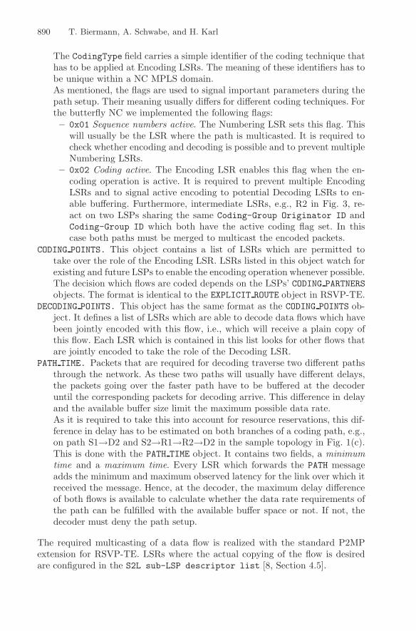
PATH TIME. Packets that are required for decoding traverse two different pathsthrough the network. As these two paths will usually have different delays,the packets going over the faster path have to be buffered at the decoderuntil the corresponding packets for decoding arrive. This difference in delayand the available buffer size limit the maximum possible data rate.As it is required to take this into account for resource reservations, this dif-ference in delay has to be estimated on both branches of a coding path, e.g.,on path S1→D2 and S2→R1→R2→D2 in the sample topology in Fig. 1(c).This is done with the PATH TIME object. It contains two fields, a minimumtime and a maximum time. Every LSR which forwards the PATH messageadds the minimum and maximum observed latency for the link over which itreceived the message. Hence, at the decoder, the maximum delay differenceof both flows is available to calculate whether the data rate requirements ofthe path can be fulfilled with the available buffer space or not. If not, thedecoder must deny the path setup.
The required multicasting of a data flow is realized with the standard P2MPextension for RSVP-TE. LSRs where the actual copying of the flow is desiredare configured in the S2L sub-LSP descriptor list [8, Section 4.5].
Creating Butterflies in the Core 891
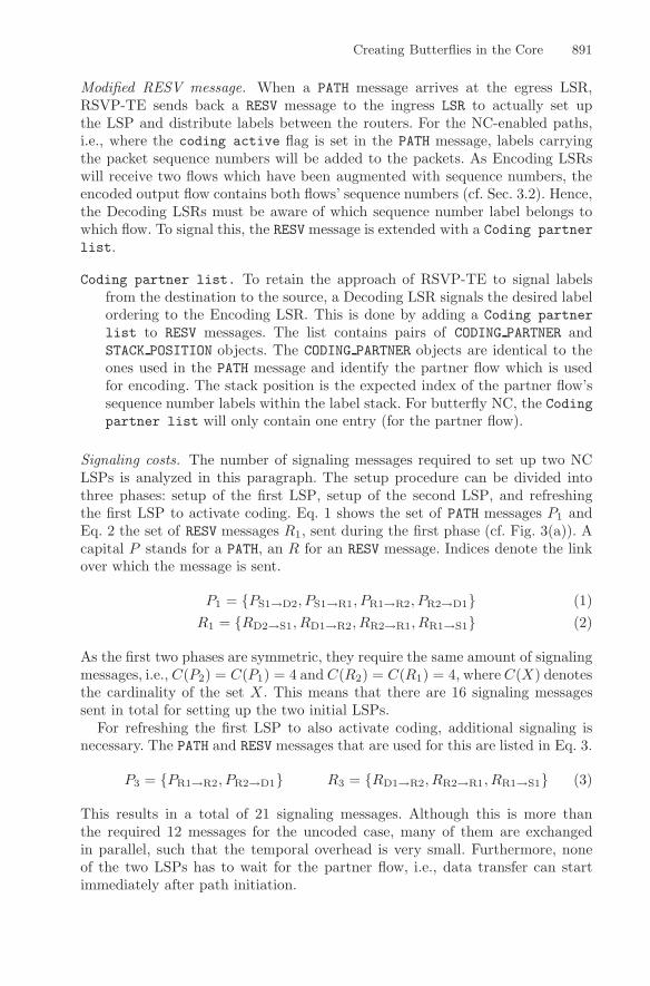
Modified RESV message. When a PATH message arrives at the egress LSR,RSVP-TE sends back a RESV message to the ingress LSR to actually set upthe LSP and distribute labels between the routers. For the NC-enabled paths,i.e., where the coding active flag is set in the PATH message, labels carryingthe packet sequence numbers will be added to the packets. As Encoding LSRswill receive two flows which have been augmented with sequence numbers, theencoded output flow contains both flows’ sequence numbers (cf. Sec. 3.2). Hence,the Decoding LSRs must be aware of which sequence number label belongs towhich flow. To signal this, the RESV message is extended with a Coding partnerlist.
Coding partner list. To retain the approach of RSVP-TE to signal labelsfrom the destination to the source, a Decoding LSR signals the desired labelordering to the Encoding LSR. This is done by adding a Coding partnerlist to RESV messages. The list contains pairs of CODING PARTNER andSTACK POSITION objects. The CODING PARTNER objects are identical to theones used in the PATH message and identify the partner flow which is usedfor encoding. The stack position is the expected index of the partner flow’ssequence number labels within the label stack. For butterfly NC, the Codingpartner list will only contain one entry (for the partner flow).
Signaling costs. The number of signaling messages required to set up two NCLSPs is analyzed in this paragraph. The setup procedure can be divided intothree phases: setup of the first LSP, setup of the second LSP, and refreshingthe first LSP to activate coding. Eq. 1 shows the set of PATH messages P1 andEq. 2 the set of RESV messages R1, sent during the first phase (cf. Fig. 3(a)). Acapital P stands for a PATH, an R for an RESV message. Indices denote the linkover which the message is sent.
P1 = {PS1→D2, PS1→R1, PR1→R2, PR2→D1} (1)R1 = {RD2→S1, RD1→R2, RR2→R1, RR1→S1} (2)
As the first two phases are symmetric, they require the same amount of signalingmessages, i.e., C(P2) = C(P1) = 4 and C(R2) = C(R1) = 4, where C(X) denotesthe cardinality of the set X . This means that there are 16 signaling messagessent in total for setting up the two initial LSPs.
For refreshing the first LSP to also activate coding, additional signaling isnecessary. The PATH and RESV messages that are used for this are listed in Eq. 3.
P3 = {PR1→R2, PR2→D1} R3 = {RD1→R2, RR2→R1, RR1→S1} (3)
This results in a total of 21 signaling messages. Although this is more thanthe required 12 messages for the uncoded case, many of them are exchangedin parallel, such that the temporal overhead is very small. Furthermore, noneof the two LSPs has to wait for the partner flow, i.e., data transfer can startimmediately after path initiation.

892 T. Biermann, A. Schwabe, and H. Karl
4.2 Tearing Down Network-Coded Paths
Tearing down one of the jointly encoded paths is straightforward. The sourceLSR of the LSP to be torn down sends a PathTear message down the path. TheEncoding LSR receives this message and stops encoding both flows from thenon. As packets of the partner path still have to reach their destination, they aresent uncoded and the special sequence number 0 is used to signal this to thedecoder (cf. Sec. 3.2).
Using this method guarantees a disruption-free operation of paths whose part-ners are torn down during NC operations. Depending on the application scenario,a conversion of the multicast LSP to a unicast LSP after such an event might bereasonable to save capacity. This is the case if the multicast capability has onlybeen set up to do NC and is not further required. Such a conversion is done bythe ingress LSR by additionally setting up a normal unicast LSP which uses thealready allocated network ressources. After switching the traffic to the unicastLSP, the NC multicast LSP is torn down.
5 Evaluation
To demonstrate the feasibility of our protocol extensions, we implemented themin a simulator. The system model and the observed results are discussed next.
5.1 System Model
We implemented the topology already presented in Fig. 1(c) using the OM-NeT++ discrete event simulator and the MPLS and RSVP-TE models fromthe INET framework. The data sources and destinations are outside the butter-fly. All links are equal and have a capacity of 10Mbit/s and a latency of 2 ms.The sources, connected to S1 and S2, periodically send packets of 1435byte tothe destinations, which are connected to D1 and D2, with inter-packet times of13ms. This is the minimum possible inter-packet time before congestion occursat the chosen link configuration. RSVP-TE refreshes paths every 5 s.
To demonstrate NC, the following events occur at the simulated times t:
t = 0 s: S1 creates a normal LSP without coding functionality (LSP1-1). Thesource at S1 starts sending packets which are transported through LSP1-1.
t = 4 s: S1 creates an NC-enabled LSP (LSP1-2) in parallel to LSP1-1.t = 4.5 s: The data packets from S1 are switched from LSP1-1 to LSP1-2. LSP1-1
is torn down. The encoding of LSP1-2 is still inactive.t = 5 s: S2 creates an NC-enabled LSP (LSP2-1). This triggers the joint coding
for LSP1-2 and LSP2-1 at R1.t = 6 s: Source at S2 starts sending packets.t = 15 s: Source at S1 stops sending packets. LSP1-2 is torn down.
During the simulation, the end-to-end delay d is measured for each packet to seechanges in the packet forwarding behavior. Furthermore, packet loss is monitoredto detect possible problems during path switching. Nevertheless, the point ofthis simulation is not a stochastic performance evaluation but rather serves tovalidate the protocol. Therefore, a variation of parameters is not necessary.
Creating Butterflies in the Core 893
0 2 4 6 8 10 12 14 16 18 20
55
60
65
70
75
Simulated time t [s]
End
−to
−en
d la
tenc
y [m
s]
S1 → D1S2 → D2
(3)
(1)
(2)
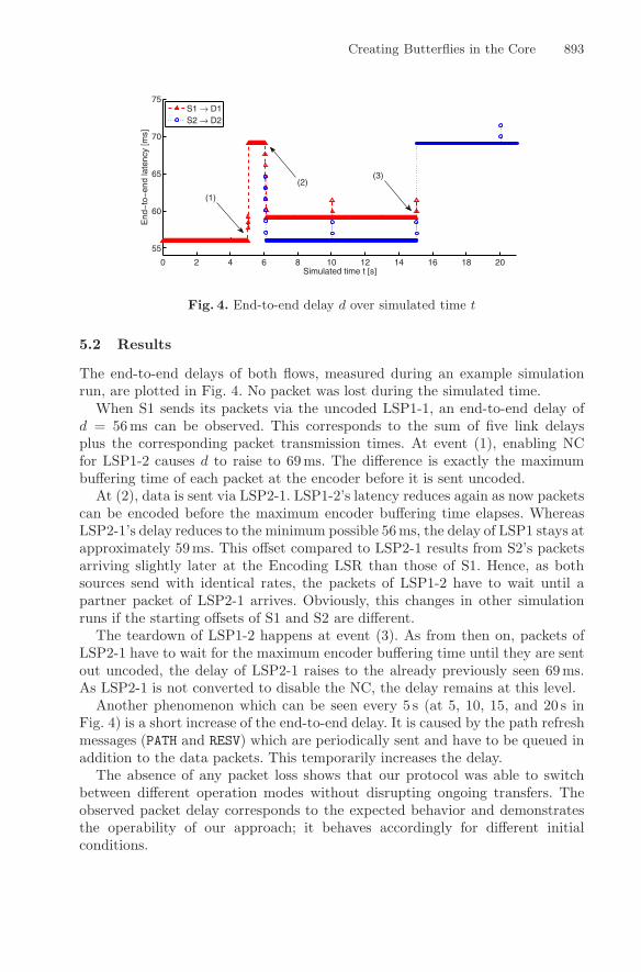
Fig. 4. End-to-end delay d over simulated time t
5.2 Results
The end-to-end delays of both flows, measured during an example simulationrun, are plotted in Fig. 4. No packet was lost during the simulated time.
When S1 sends its packets via the uncoded LSP1-1, an end-to-end delay ofd = 56ms can be observed. This corresponds to the sum of five link delaysplus the corresponding packet transmission times. At event (1), enabling NCfor LSP1-2 causes d to raise to 69ms. The difference is exactly the maximumbuffering time of each packet at the encoder before it is sent uncoded.
At (2), data is sent via LSP2-1. LSP1-2’s latency reduces again as now packetscan be encoded before the maximum encoder buffering time elapses. WhereasLSP2-1’s delay reduces to the minimum possible 56ms, the delay of LSP1 stays atapproximately 59ms. This offset compared to LSP2-1 results from S2’s packetsarriving slightly later at the Encoding LSR than those of S1. Hence, as bothsources send with identical rates, the packets of LSP1-2 have to wait until apartner packet of LSP2-1 arrives. Obviously, this changes in other simulationruns if the starting offsets of S1 and S2 are different.
The teardown of LSP1-2 happens at event (3). As from then on, packets ofLSP2-1 have to wait for the maximum encoder buffering time until they are sentout uncoded, the delay of LSP2-1 raises to the already previously seen 69ms.As LSP2-1 is not converted to disable the NC, the delay remains at this level.
Another phenomenon which can be seen every 5 s (at 5, 10, 15, and 20 s inFig. 4) is a short increase of the end-to-end delay. It is caused by the path refreshmessages (PATH and RESV) which are periodically sent and have to be queued inaddition to the data packets. This temporarily increases the delay.
The absence of any packet loss shows that our protocol was able to switchbetween different operation modes without disrupting ongoing transfers. Theobserved packet delay corresponds to the expected behavior and demonstratesthe operability of our approach; it behaves accordingly for different initialconditions.

894 T. Biermann, A. Schwabe, and H. Karl
6 Conclusion
We presented an extension to the MPLS and RSVP-TE protocols to support creat-ing network-coded paths. The decision whether to use coding or not does not haveto be made during the paths’ initiation; seamless switching between non-codedand coded operation is possible. Another advantage of the protocol extension isthat only those LSRs have to be modified which are actually involved in the cod-ing operation. All others, e.g., intermediate routers which forward coded packets,can remain untouched. Compared to traditional packet forwarding, our extensionenables new load distribution schemes which are especially useful for the operationof core networks.
References
1. Fragouli, C., Boudec, J.Y.L., Widmer, J.: Network coding: An instant primer. SIG-COMM Comput. Commun. Rev. 36(1), 63–68 (2006)
2. Katti, S., Rahul, H., Hu, W., Katabi, D., Medard, M., Crowcroft, J.: XORs in theair: Practical wireless network coding. SIGCOMM Comput. Commun. Rev. 36(4),243–254 (2006)
3. Chaporkar, P., Proutiere, A.: Adaptive network coding and scheduling for maximiz-ing throughput in wireless networks. In: MobiCom, pp. 135–146. ACM, New York(2007)
4. Gkantsidis, C., Rodriguez, P.R.: Network coding for large scale content distribution.In: INFOCOM 2005, vol. 4, pp. 2235–2245 (2005)
5. Wang, C.C., Shroff, N.B.: Beyond the butterfly – a graph-theoretic characterizationof the feasibility of network coding with two simple unicast sessions. In: Proc. IEEEIntl. Symp. on Information Theory, Nice, France (June 2007)
6. Rosen, E., Viswanathan, A., Callon, R.: Multiprotocol Label Switching Architecture.RFC 3031 (Proposed Standard) (January 2001)
7. Awduche, D., Berger, L., Gan, D., Li, T., Srinivasan, V., Swallow, G.: RSVP-TE:Extensions to RSVP for LSP Tunnels. RFC 3209 (Proposed Standard), Updated byRFCs 3936, 4420, 4874, 5151 (December 2001)
8. Aggarwal, R., Papadimitriou, D., Yasukawa, S.: Extensions to Resource Reserva-tion Protocol - Traffic Engineering (RSVP-TE) for Point-to-Multipoint TE LabelSwitched Paths (LSPs). RFC 4875 (Proposed Standard) (May 2007)