Create Basic 3d Objects Acdmac
12
Creating Basic 3D Ob- jects Products: AutoCAD 2011 for Mac or later Audience: New users to 3D Prerequisites: Working knowledge of 2D drafting Time to complete: 15 minutes Download the Tutorial File Before beginning the lessons, download the tutorial. ■ Download create_basic_3d_objects_acdmac.zip from http://www.autodesk.com/autocadformac-tutorials. In This Tutorial The lessons in this tutorial do not need to be completed in the presented order. In this tutorial, you learn how to do the following: ■ Create 3D solid primitives: box, cylinder, cone, and torus ■ Create simple 3D objects from 2D objects NOTE For more information on the topics covered in this tutorial, see the product User’ s Guide. Lesson: Create 3D Solid Primitives In this lesson, you learn how to create 3D solid primitives from the Modeling tool set. 1 1
-
Upload
julio-aragon -
Category
Documents
-
view
227 -
download
1
Transcript of Create Basic 3d Objects Acdmac

Creating Basic 3D Ob-jects
Products: AutoCAD 2011 for Mac or later
Audience: New users to 3D
Prerequisites: Working knowledge of 2D drafting
Time to complete: 15 minutes
Download the Tutorial File
Before beginning the lessons, download the tutorial.■ Download create_basic_3d_objects_acdmac.zip from
http://www.autodesk.com/autocadformac-tutorials.
In This Tutorial
The lessons in this tutorial do not need to be completed in the presented order. In this tutorial,you learn how to do the following:■ Create 3D solid primitives: box, cylinder, cone, and torus
■ Create simple 3D objects from 2D objects
NOTE For more information on the topics covered in this tutorial, see the product User’s Guide.
Lesson: Create 3D Solid PrimitivesIn this lesson, you learn how to create 3D solid primitives from the Modelingtool set.
1
1

A 3D solid primitive is a standard 3D solid objects in the shape of a box, cone,cylinder, sphere, torus, wedge, or pyramid. You can resize primitives orcombine them with other objects. To create 3D solid primitives, switch to theModeling tool set, that contains tools to create and modify 3D solid models.
To switch to the Modeling tool set
■ On the Tool Sets palette, click the Tool Set button and click Modeling.
If the Tool Sets palette is not displayed, on the menu bar, click Tools menu ➤ Palettes ➤ Tool Set (or press Cmd-1).
The Modeling tool set is displayed.
Create a Box
Boxes can be rectangular or cubical.
2 | Chapter 1 Creating Basic 3D Objects

To create a box
1 In the drawing area, click the Visual Styles viewport label menu andchoose Conceptual.
2 On the Tool Sets palette, click Modeling tool set ➤ Solids – Create tool
group ➤ Solid Primitives flyout ➤ Box.
3 At the Specify first corner prompt, click in the drawing area to specifythe box’s base point.
4 At the Specify other corner prompt, enter @8,8 to define the oppositecorner and press Enter.
5 At the Specify height prompt, enter 5 and press Enter.
Lesson: Create 3D Solid Primitives | 3

The base of the box is always drawn on the XY plane (or work plane) ofthe current UCS. The height of the box is specified in the Z axis direction.You can enter both positive and negative values for the height.
6 On the ViewCube tool, located in the upper-right corner of the drawingarea, click Top to center the box. Then click the lower-left corner of theViewCube tool to see an isometric view of the box.
NOTE For more information on the ViewCube tool, see the product User'sGuide.
Create a Cylinder
Cylinders can have a circular or elliptical base.
4 | Chapter 1 Creating Basic 3D Objects

To create a cylinder
1 On the Tool Sets palette, click Modeling tool set ➤ Solids – Create tool
group ➤ Cylinder.
2 At the Specify center point of base prompt, specify the base pointin the drawing area.
3 At the Specify base radius prompt, enter 5 and press Enter.
4 At the Specify height prompt, enter 8 and press Enter.
Create a Cone
Cones can have a circular or elliptical base, and can taper into a point or planarface (creating a cone frustum).
To create a cone
1 On the Tool Sets palette, click Modeling tool set ➤ Solids – Create tool
group ➤ Solid Primitives flyout ➤ Cone.
2 At the Specify center point of base prompt, specify the base pointin the drawing area.
3 At the Specify base radius prompt, enter 7 and press Enter.
4 At the Specify height prompt, enter 5 and press Enter.
Create a Torus
Tori are doughnut-shaped primitives defined by two radii; think of it as acircle revolved around a circular path. The first radius defines the distance
Lesson: Create 3D Solid Primitives | 5

from the center of the torus to the center of tube. The second radius definesthe tube.
To create a torus
1 On the Tool Sets palette, click Modeling tool set ➤ Solids – Create tool
group ➤ Solid Primitives flyout ➤ Torus.
2 At the Specify center point prompt, specify the center point in thedrawing area.
3 At the Specify radius prompt, enter 8 and press Enter.
4 At the Specify tube radius prompt, enter 3 and press Enter.
Lesson: Create Simple 3D Objects from 2D ObjectsIn this lesson, you create simple 3D objects from 2D objects.
You can create simple and complex objects by combining and modifying basic3D shapes. You can also extrude 2D objects to create solids and surfaces byadding height. A surface is a type of 3D object that has no thickness.
6 | Chapter 1 Creating Basic 3D Objects

To draw a table stand with simple 3D solid primitives
1 On the menu bar, click File menu ➤ Open.
2 In the Open dialog box, browse to and select create_table.dwg. Click Open.
3 On the viewport label menus, click the Visual Styles menu and clickConceptual.
TIP If you have trouble selecting objects, change the current visual style to3D Wireframe.
4 On the status bar, click the Object Snap button to enable Object Snapmode. Right-click the Object Snap button.
5 On the shortcut menu, click Center. The Center option should now havea check mark next to it to indicate the object snap is enabled.
Lesson: Create Simple 3D Objects from 2D Objects | 7

6 On the Tool Sets palette, click Modeling tool set ➤ Solids – Create tool
group ➤ Solid Primitives flyout ➤ Cone.
7 At the Specify center point of base prompt, move the cursor overone of the small circles. An AutoSnap marker appears at the center ofthe circle. Click when the marker is displayed to snap to the center ofthe circle.
8 At the Specify base radius prompt, enter 0.3 and press Enter.
9 At the Specify height prompt, enter T for top radius and press Enter.
10 At the Specify top radius prompt, enter 0.5 and press Enter.
8 | Chapter 1 Creating Basic 3D Objects

11 At the Specify height prompt, move the cursor below the table surface.Enter 4 for the height and press Enter.
12 Repeat the process on the other small circles in the drawing to createfour table legs.
To draw a tabletop with a simple 3D solid primitive
1 In the same drawing file, on the Tool Sets palette, click Modeling tool
set ➤ Solids – Create tool group ➤ Cylinder.
2 At the Specify center point of base prompt, select the center pointof the large circle.
Lesson: Create Simple 3D Objects from 2D Objects | 9
3 At the Specify base radius prompt, enter 4 and press Enter.
4 At the Specify height prompt, enter 0.5 and press Enter.
To extrude an object to create walls
1 On the menu bar, click File menu ➤ Open.
2 In the Open dialog box, browse to and select create_wall.dwg. Click Open.
10 | Chapter 1 Creating Basic 3D Objects
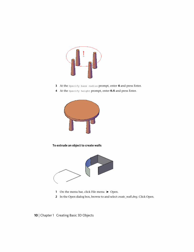
3 On the Tool Sets palette, click Modeling tool set ➤ Solids – Create tool
group ➤ Extrude.
4 At the Select objects to extrude prompt, select the three rectanglesand press Enter.
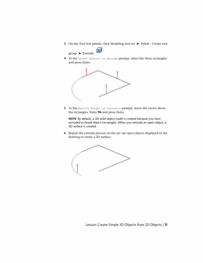
5 At the Specify height of extrusion prompt, move the cursor abovethe rectangles. Enter 96 and press Enter.
NOTE By default, a 3D solid object (wall) is created because you haveextruded a closed object (rectangle). When you extrude an open object, a3D surface is created.
6 Repeat the extrude process on the arc (an open object) displayed in thedrawing to create a 3D surface.
Lesson: Create Simple 3D Objects from 2D Objects | 11

12


![3D Reconstruction of Transparent Objects With Position ... · 3D Reconstruction of Transparent Objects with Position-Normal Consistency ... Tarini et al. [30] acquire light ... 3D](https://static.fdocuments.in/doc/165x107/5b1dab1e7f8b9a8e158bb5b7/3d-reconstruction-of-transparent-objects-with-position-3d-reconstruction.jpg)