CREASING SCORING FOLDING EMBOSSING · CREASING SCORING FOLDING EMBOSSING Are critical steps in the...
53
CREASING SCORING FOLDING EMBOSSING Are critical steps in the box forming process Dipl. Ing. Lukas Pescoller
Transcript of CREASING SCORING FOLDING EMBOSSING · CREASING SCORING FOLDING EMBOSSING Are critical steps in the...
CREASING
SCORING
FOLDING
EMBOSSINGAre critical steps in the box forming process
Dipl. Ing. Lukas Pescoller
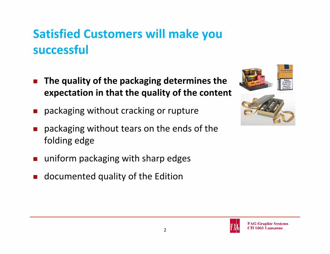
Satisfied Customers will make you successful
The quality of the packaging determines the expectation in that the quality of the content
packaging without cracking or rupture
packaging without tears on the ends of the folding edge
uniform packaging with sharp edges
documented quality of the Edition
2

Reputation through quality assurance
Constant quality from job to job, from machine to machine and from site to site
Documentation of quality over time
Specify reference numbers and tolerances
Detecting process variations and improvement opportunities
Process Chain or Supply Chain?Who defines what to do?
3
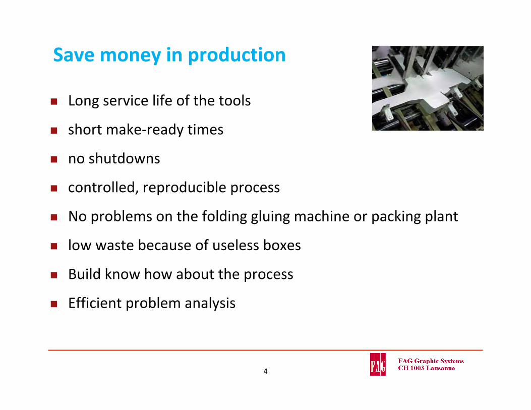
Save money in production
Long service life of the tools
short make‐ready times
no shutdowns
controlled, reproducible process
No problems on the folding gluing machine or packing plant
low waste because of useless boxes
Build know how about the process
Efficient problem analysis
4
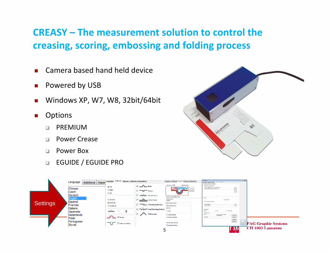
CREASY – The measurement solution to control the creasing, scoring, embossing and folding process
Camera based hand held device
Powered by USB
Windows XP, W7, W8, 32bit/64bit
Options
PREMIUM
Power Crease
Power Box
EGUIDE / EGUIDE PRO
Settings
5
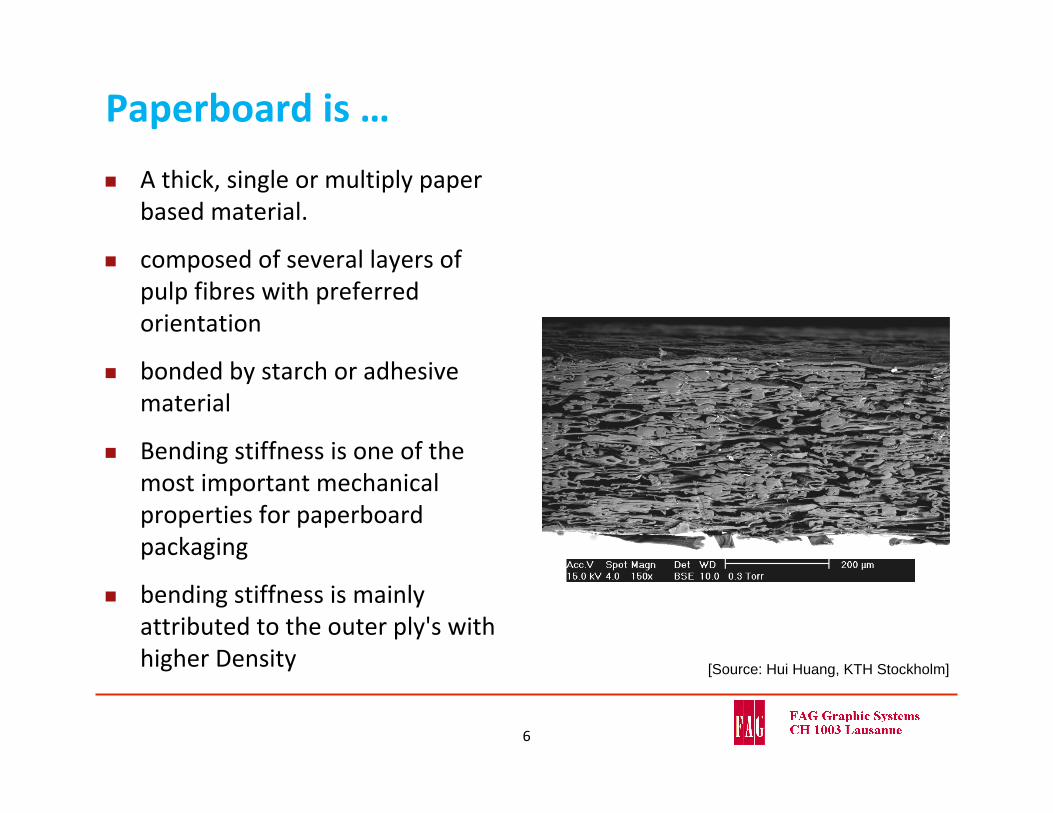
Paperboard is …
A thick, single or multiply paper based material.
composed of several layers of pulp fibres with preferred orientation
bonded by starch or adhesive material
Bending stiffness is one of the most important mechanical properties for paperboard packaging
bending stiffness is mainly attributed to the outer ply's with higher Density [Source: Hui Huang, KTH Stockholm]
6
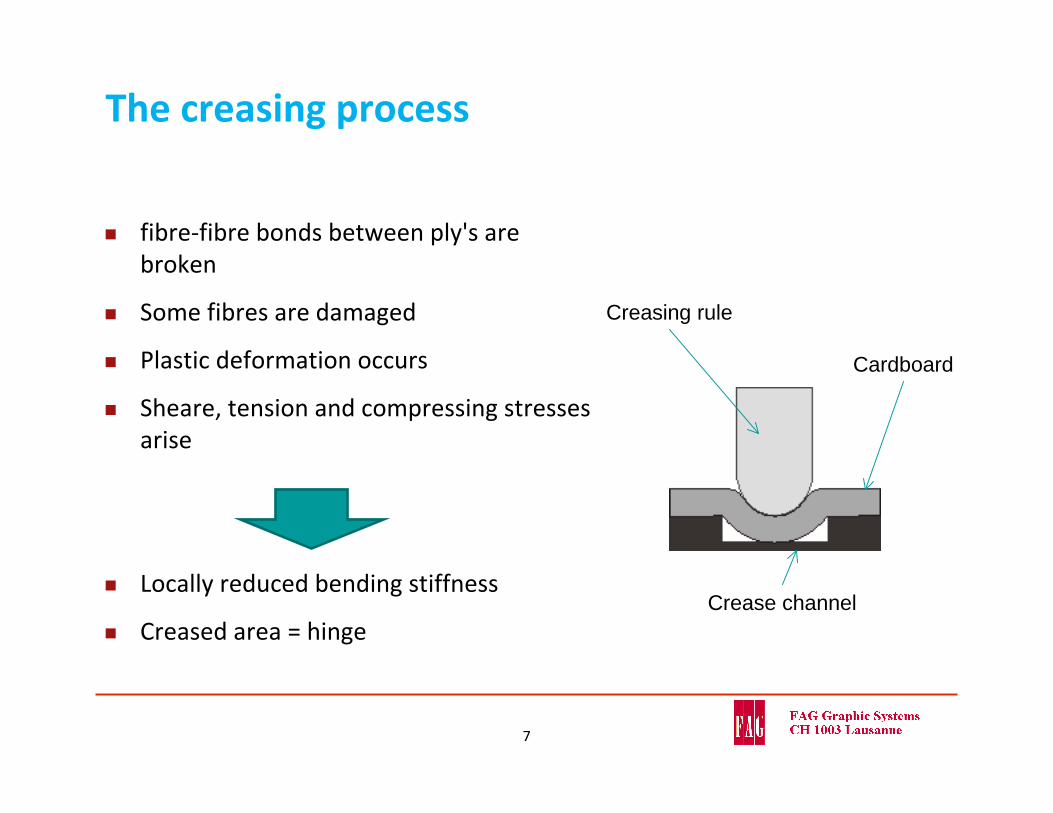
The creasing process
fibre‐fibre bonds between ply's are broken
Some fibres are damaged
Plastic deformation occurs
Sheare, tension and compressing stresses arise
Locally reduced bending stiffness
Creased area = hinge
Cardboard
Creasing rule
Crease channel
7
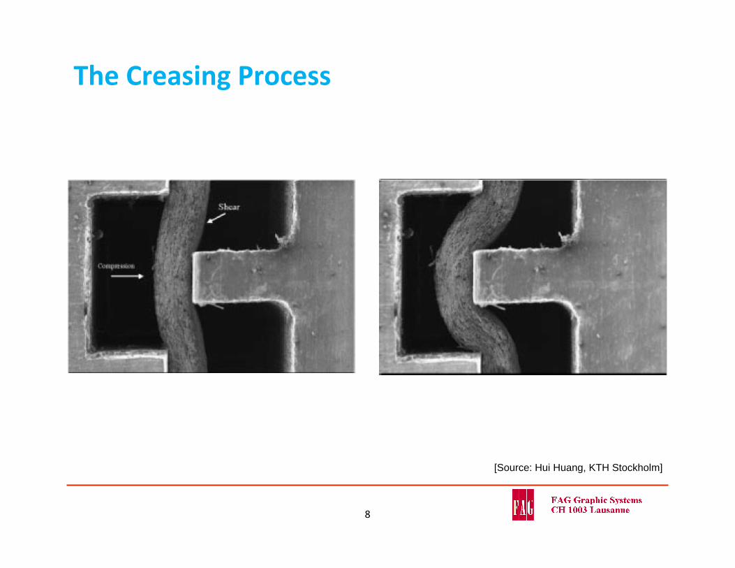
The Creasing Process
[Source: Hui Huang, KTH Stockholm]
8
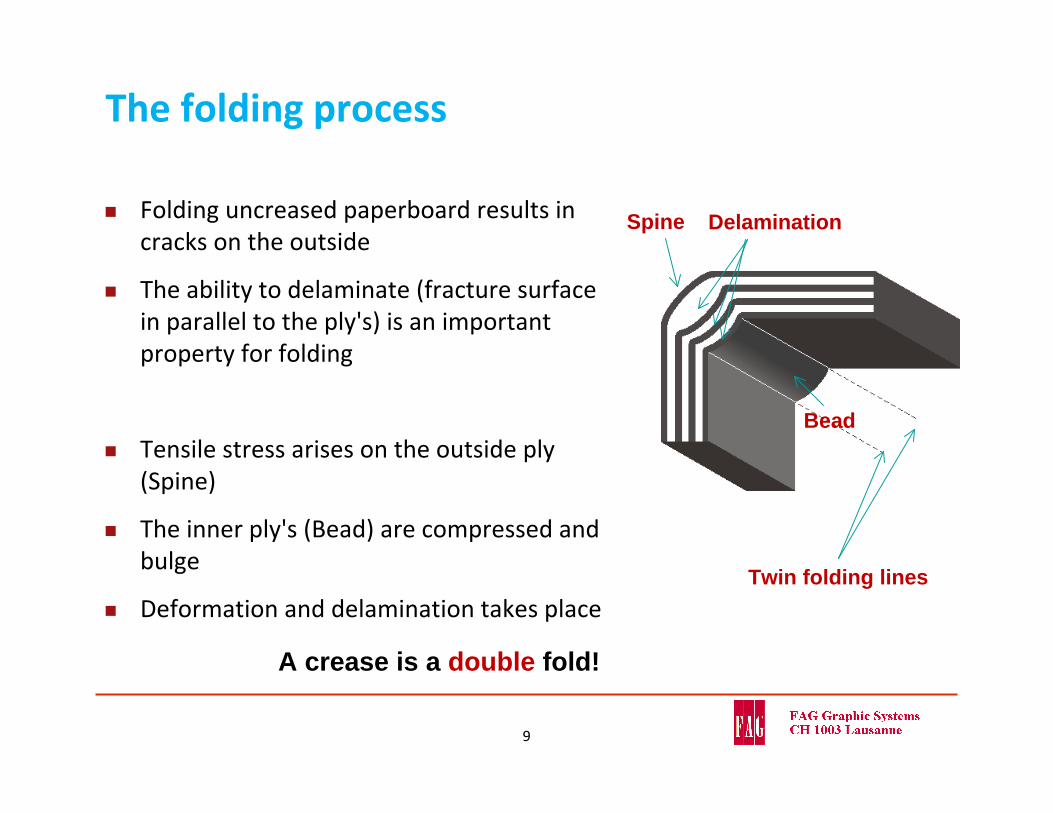
The folding process
Folding uncreased paperboard results in cracks on the outside
The ability to delaminate (fracture surface in parallel to the ply's) is an important property for folding
Tensile stress arises on the outside ply (Spine)
The inner ply's (Bead) are compressed and bulge
Deformation and delamination takes place
A crease is a double fold!
Bead
Spine
Twin folding lines
Delamination
9
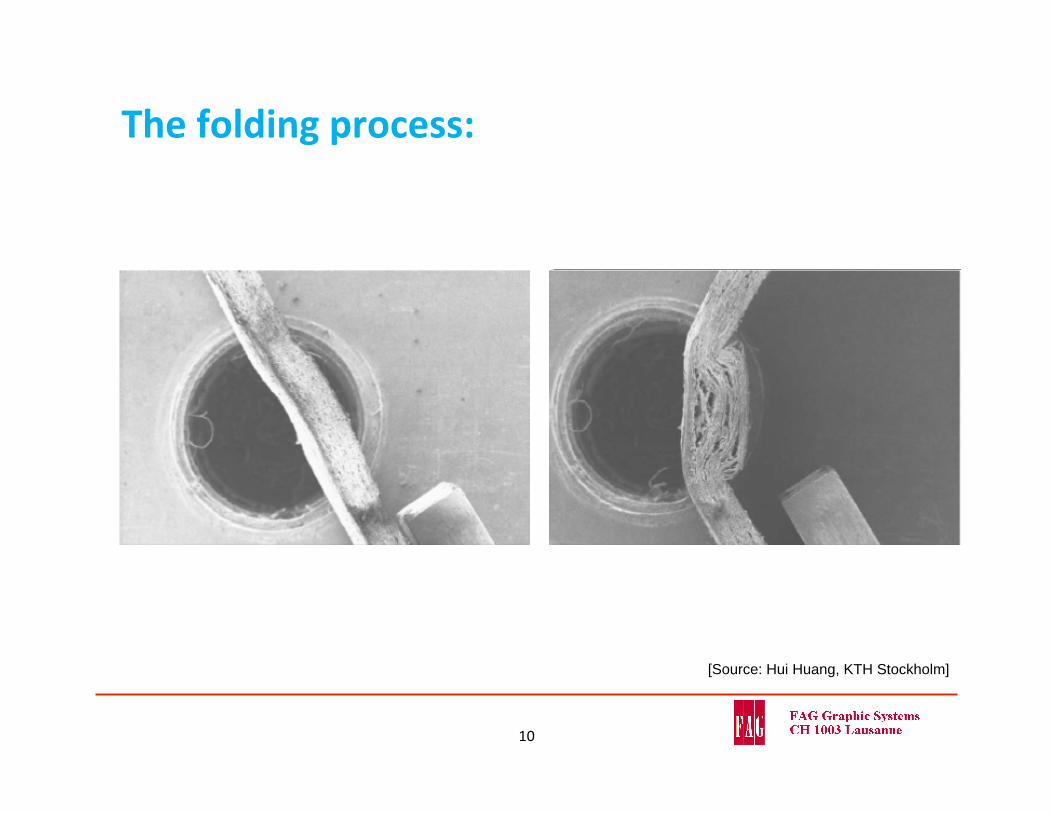
[Source: Hui Huang, KTH Stockholm]
The folding process:
10
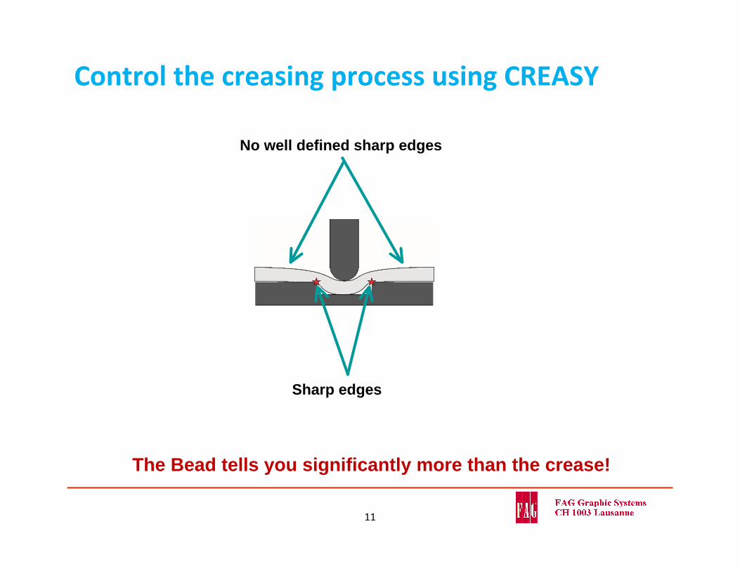
Control the creasing process using CREASY
11
The Bead tells you significantly more than the crease!
Sharp edges
No well defined sharp edges
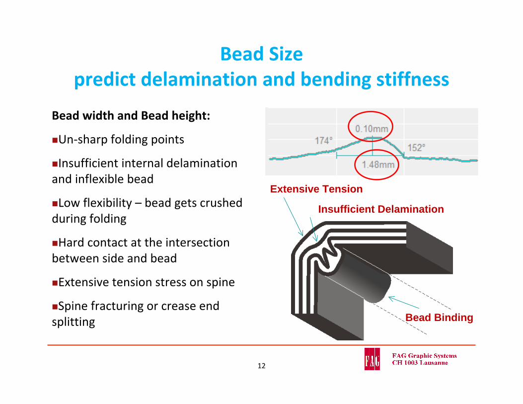
Bead Sizepredict delamination and bending stiffness
Bead width and Bead height:
Un‐sharp folding points
Insufficient internal delaminationand inflexible bead
Low flexibility – bead gets crushed during folding
Hard contact at the intersection between side and bead
Extensive tension stress on spine
Spine fracturing or crease end splitting Bead Binding
Extensive Tension
Insufficient Delamination
12
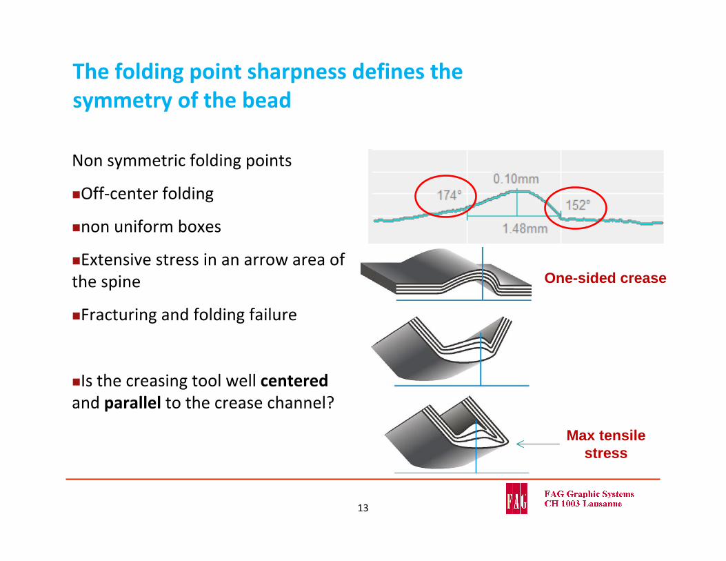
The folding point sharpness defines the symmetry of the bead
Non symmetric folding points
Off‐center folding
non uniform boxes
Extensive stress in an arrow area of the spine
Fracturing and folding failure
Is the creasing tool well centeredand parallel to the crease channel?
13
One-sided crease
Max tensilestress
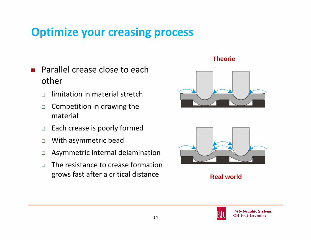
Optimize your creasing process
Parallel crease close to each other limitation in material stretch
Competition in drawing the material
Each crease is poorly formed
With asymmetric bead
Asymmetric internal delamination
The resistance to crease formation grows fast after a critical distance Real world
Theorie
14
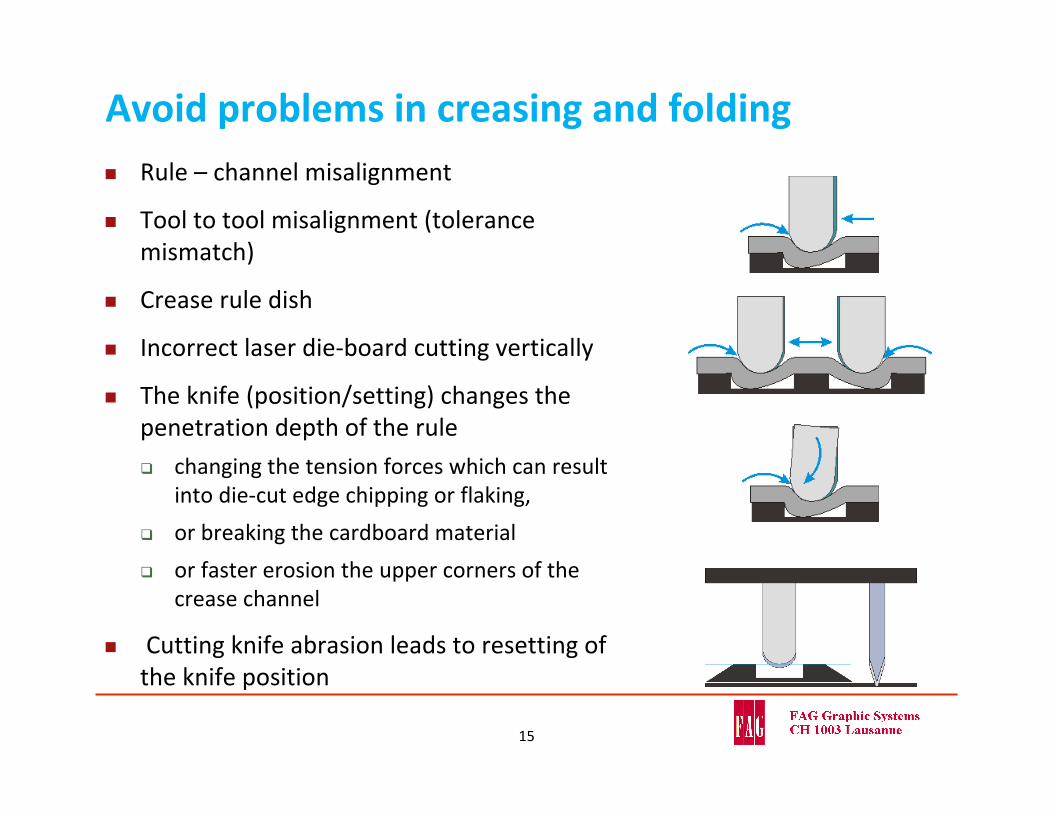
Avoid problems in creasing and folding Rule – channel misalignment
Tool to tool misalignment (tolerance mismatch)
Crease rule dish
Incorrect laser die‐board cutting vertically
The knife (position/setting) changes the penetration depth of the rule
changing the tension forces which can result into die‐cut edge chipping or flaking,
or breaking the cardboard material
or faster erosion the upper corners of the crease channel
Cutting knife abrasion leads to resetting of the knife position
15
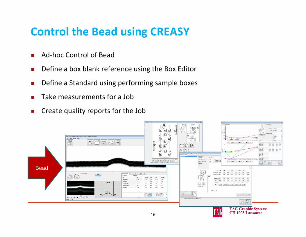
Control the Bead using CREASY
Ad‐hoc Control of Bead
Define a box blank reference using the Box Editor
Define a Standard using performing sample boxes
Take measurements for a Job
Create quality reports for the Job
Bead
16
…PAUSE…
17
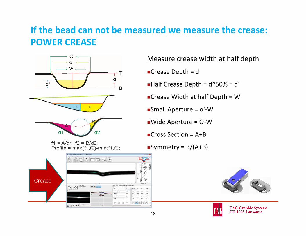
If the bead can not be measured we measure the crease: POWER CREASE
Measure crease width at half depth
Crease Depth = d
Half Crease Depth = d*50% = d‘
Crease Width at half Depth = W
Small Aperture = o‘‐W
Wide Aperture = O‐W
Cross Section = A+B
Symmetry = B/(A+B)
18
Crease
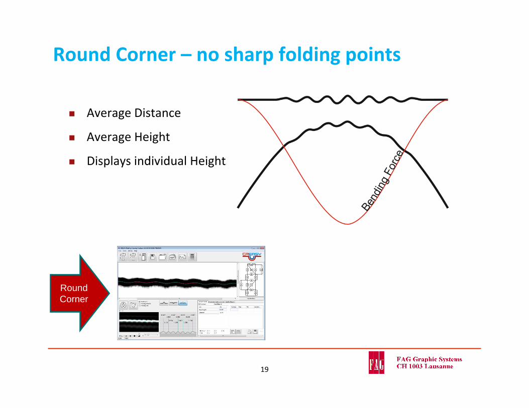
Round Corner – no sharp folding points
Average Distance
Average Height
Displays individual Heights
Round Corner
19
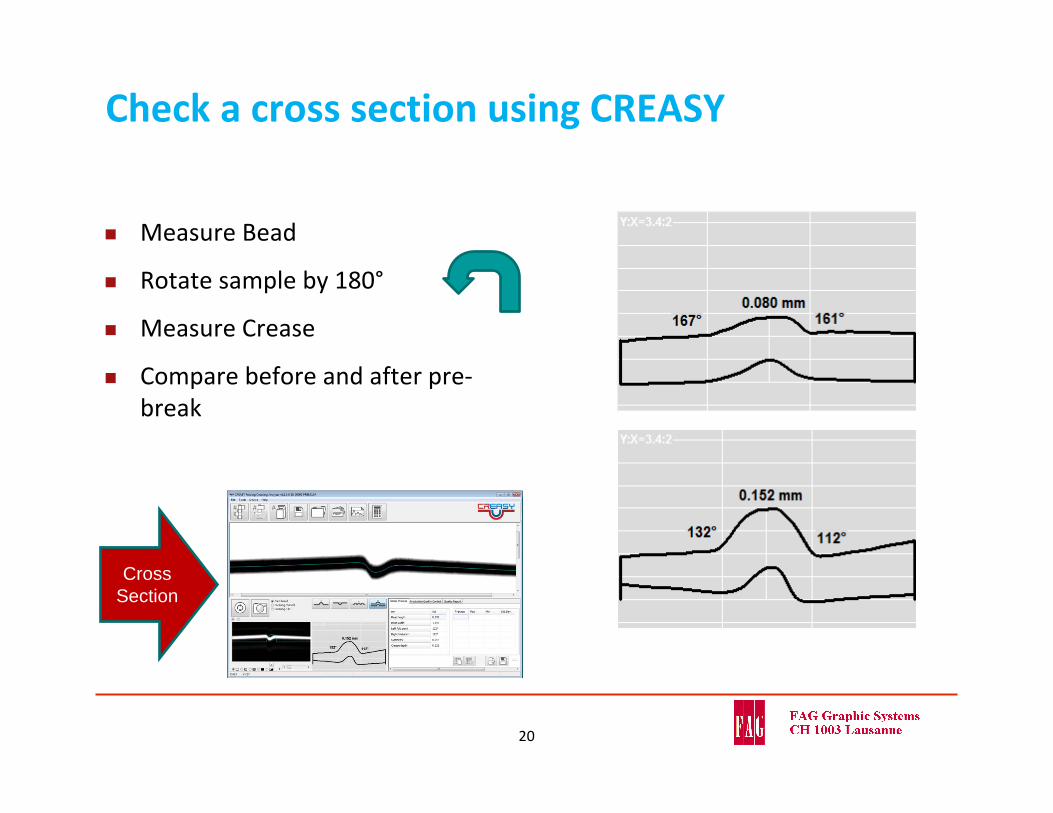
Check a cross section using CREASY
Measure Bead
Rotate sample by 180°
Measure Crease
Compare before and after pre‐break
Cross Section
20
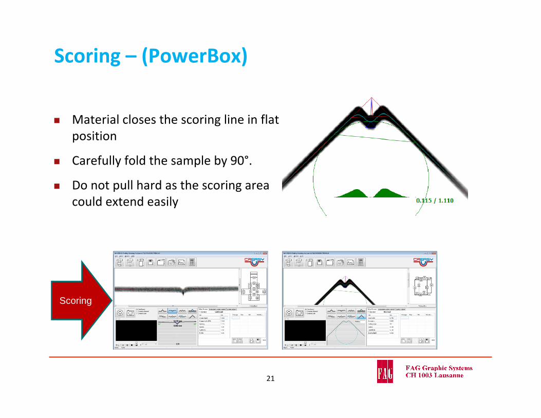
Scoring – (PowerBox)
Material closes the scoring line in flat position
Carefully fold the sample by 90°.
Do not pull hard as the scoring area could extend easily
21
Scoring
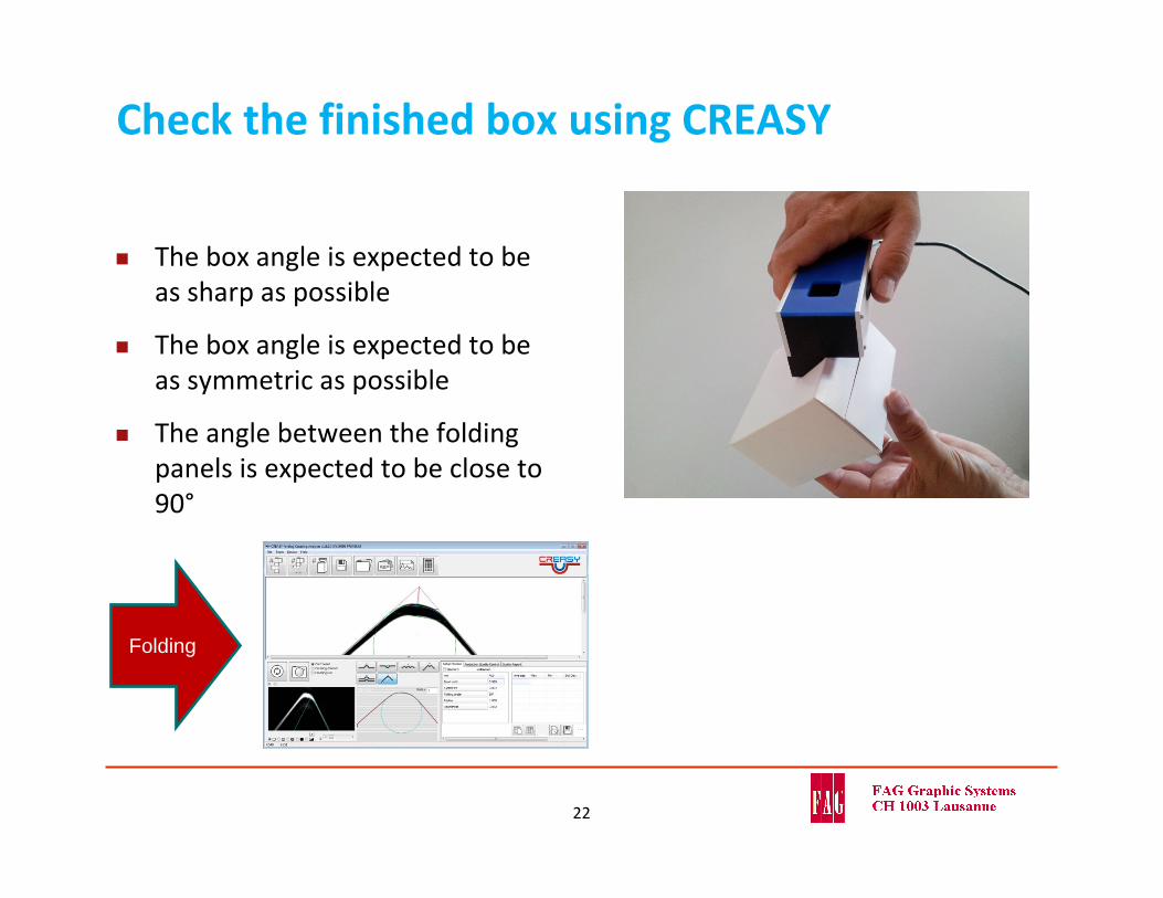
Check the finished box using CREASY
The box angle is expected to be as sharp as possible
The box angle is expected to be as symmetric as possible
The angle between the folding panels is expected to be close to 90°
22
Folding
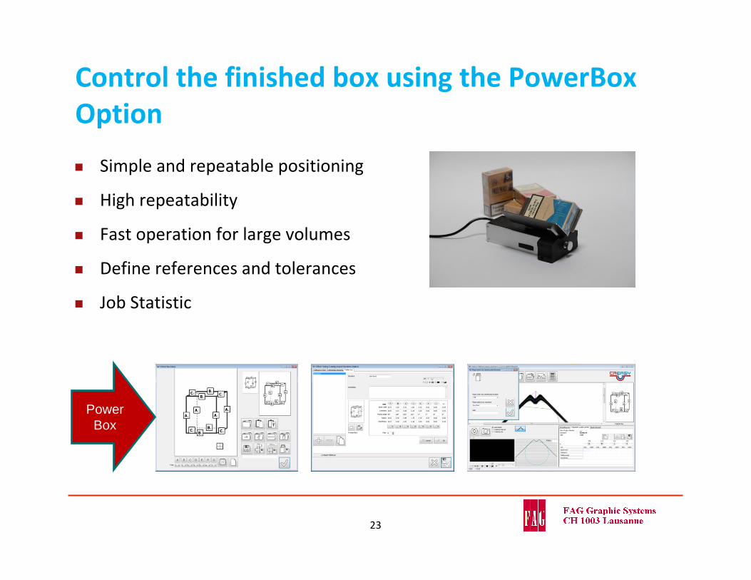
Control the finished box using the PowerBoxOption
Simple and repeatable positioning
High repeatability
Fast operation for large volumes
Define references and tolerances
Job Statistic
23
Power Box
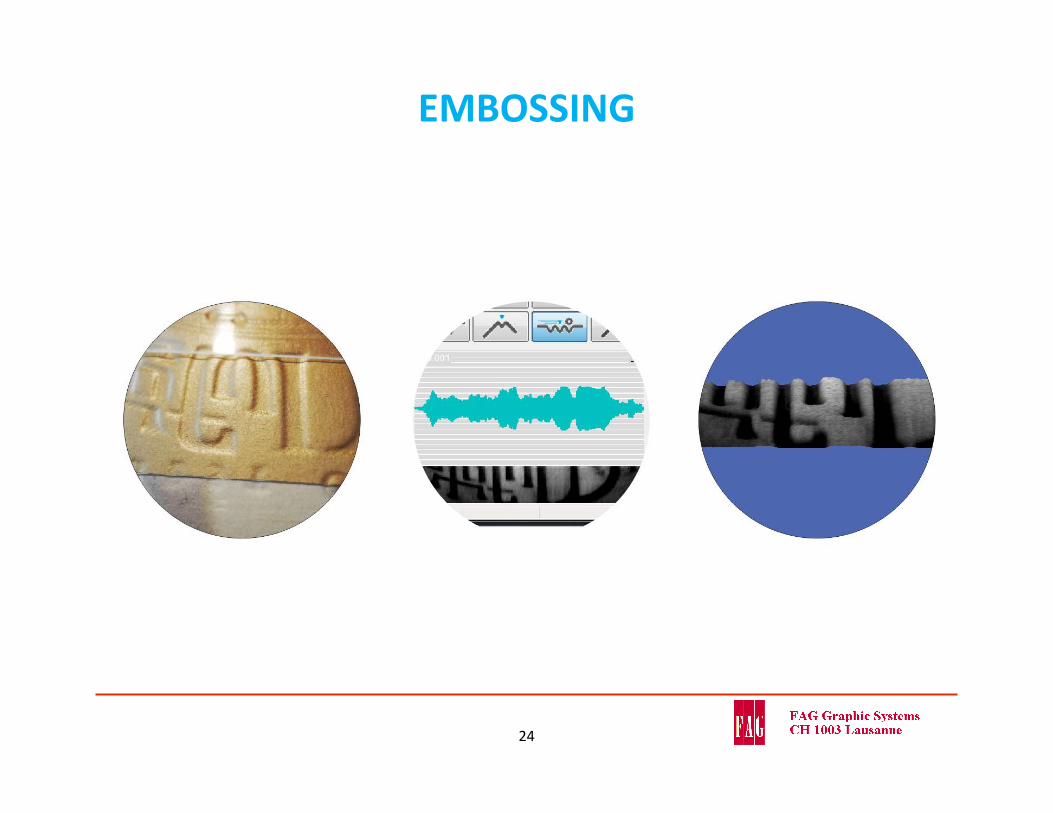
EMBOSSING
24

What is the depth of embossing?
Any embossing depth measurement tool is expected to measure the identical depth for above three embossing samples
To measure a simple average of the entire area is not appropriate as it would deliver different depth numbers for every single sample
.
25
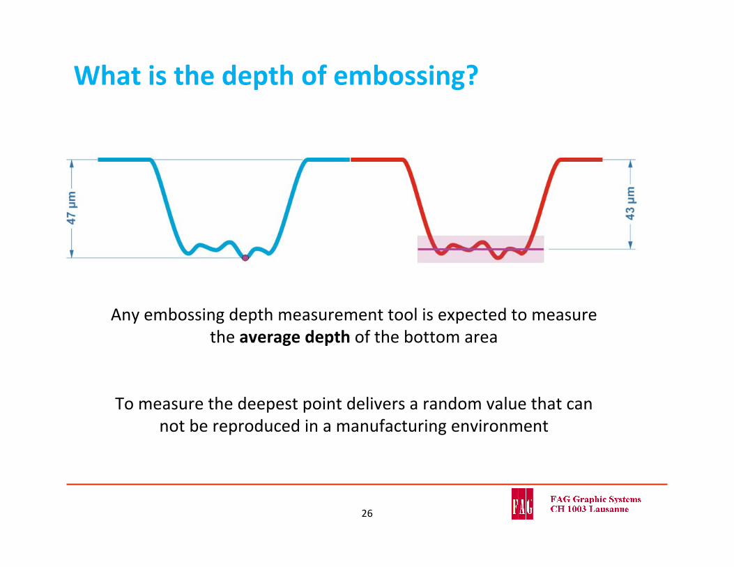
What is the depth of embossing?
Any embossing depth measurement tool is expected to measure the average depth of the bottom area
To measure the deepest point delivers a random value that can not be reproduced in a manufacturing environment
26
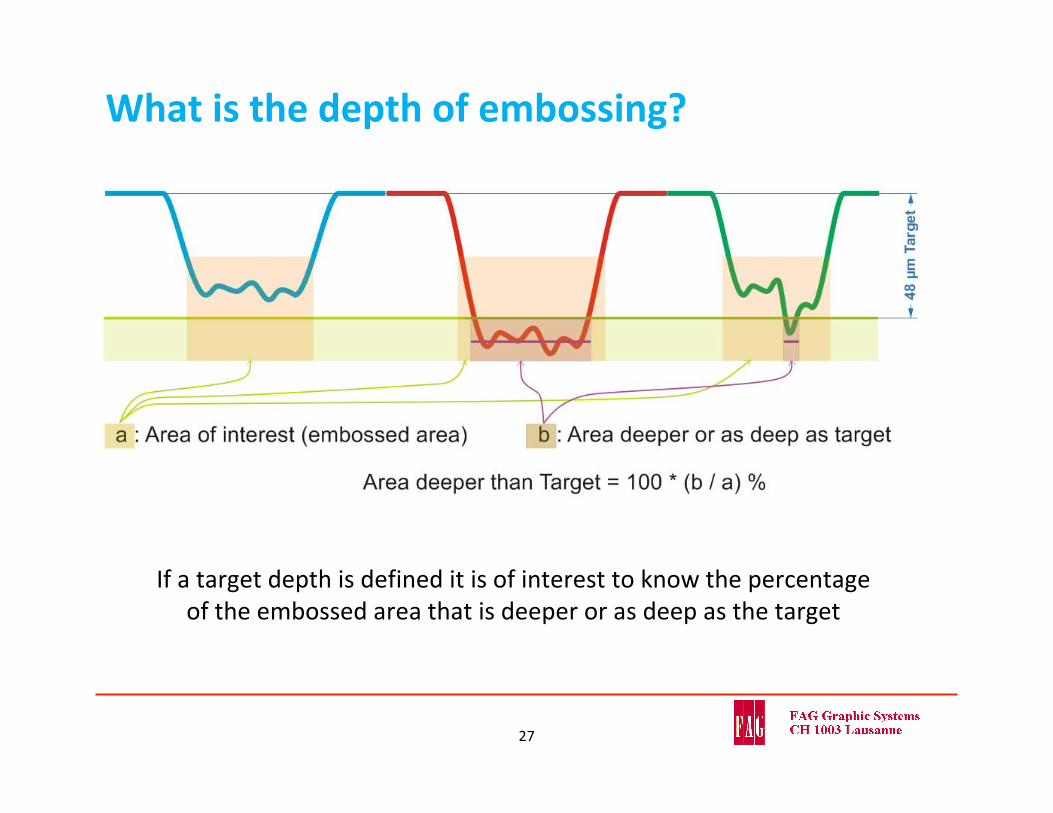
What is the depth of embossing?
If a target depth is defined it is of interest to know the percentage of the embossed area that is deeper or as deep as the target
27
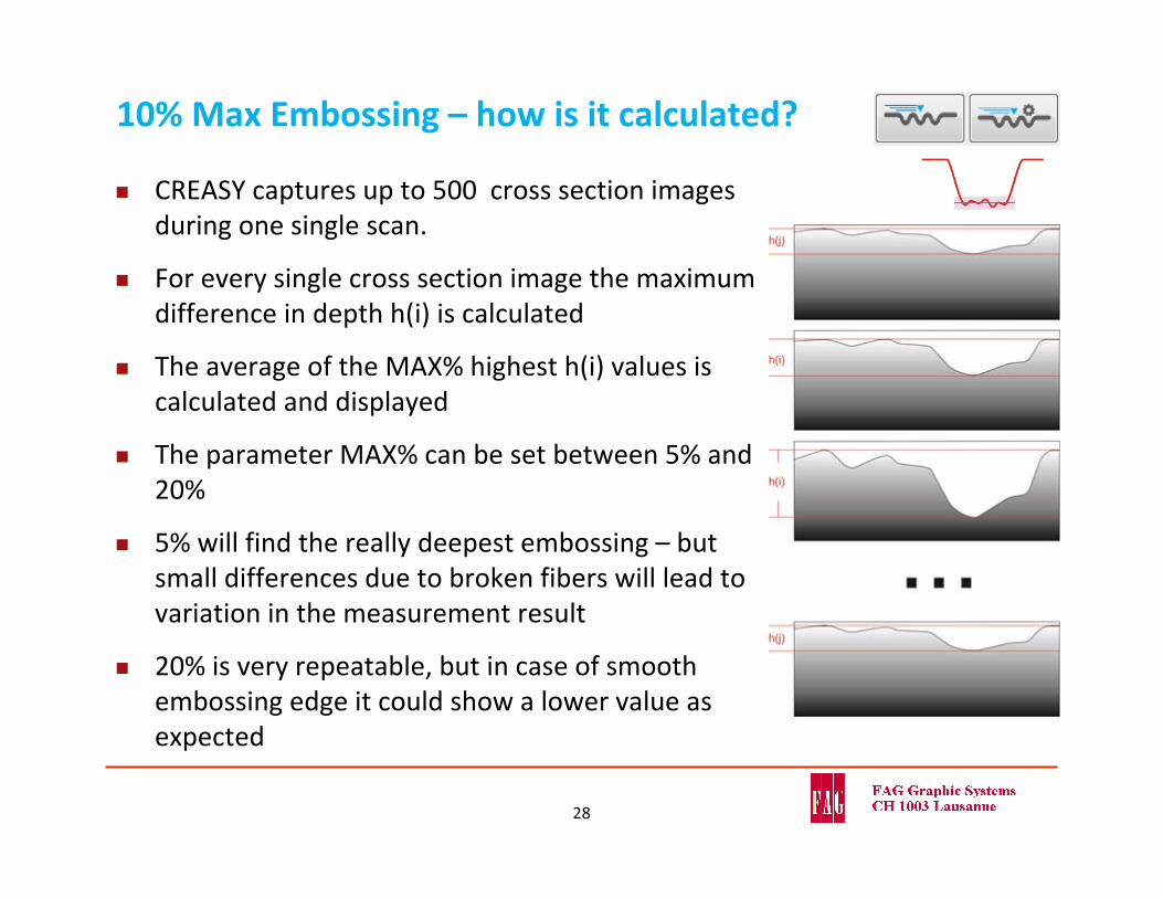
10% Max Embossing – how is it calculated?
CREASY captures up to 500 cross section images during one single scan.
For every single cross section image the maximum difference in depth h(i) is calculated
The average of the MAX% highest h(i) values is calculated and displayed
The parameter MAX% can be set between 5% and 20%
5% will find the really deepest embossing – but small differences due to broken fibers will lead to variation in the measurement result
20% is very repeatable, but in case of smooth embossing edge it could show a lower value as expected
28
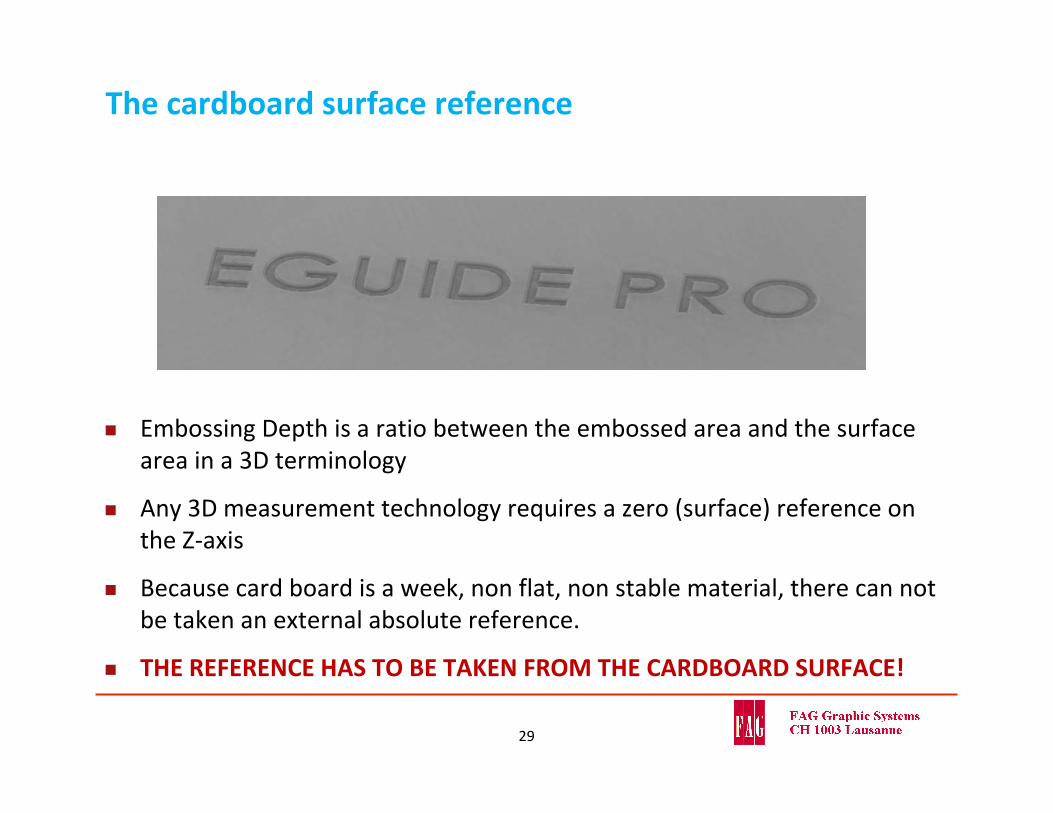
The cardboard surface reference
Embossing Depth is a ratio between the embossed area and the surface area in a 3D terminology
Any 3D measurement technology requires a zero (surface) reference on the Z‐axis
Because card board is a week, non flat, non stable material, there can not be taken an external absolute reference.
THE REFERENCE HAS TO BE TAKEN FROM THE CARDBOARD SURFACE!
29
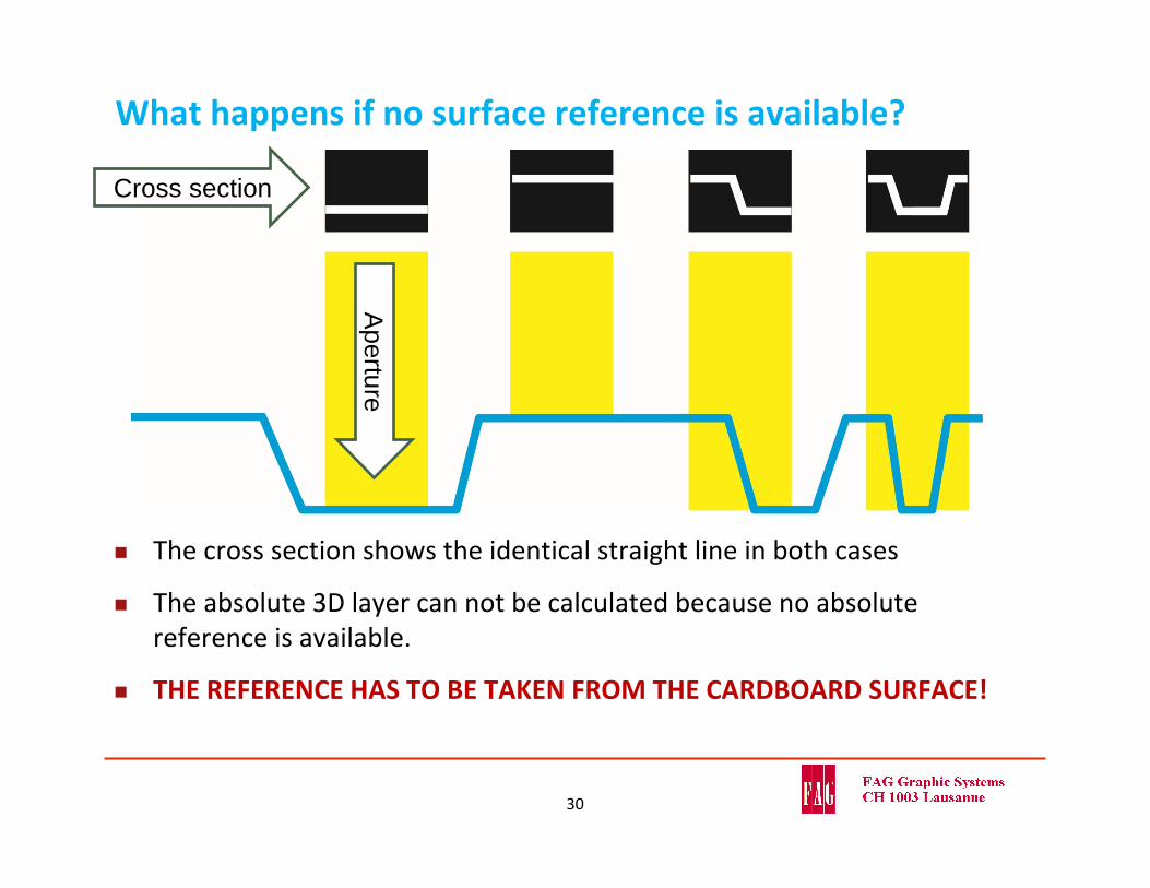
What happens if no surface reference is available?
The cross section shows the identical straight line in both cases
The absolute 3D layer can not be calculated because no absolute reference is available.
THE REFERENCE HAS TO BE TAKEN FROM THE CARDBOARD SURFACE!
30
Cross section
Aperture
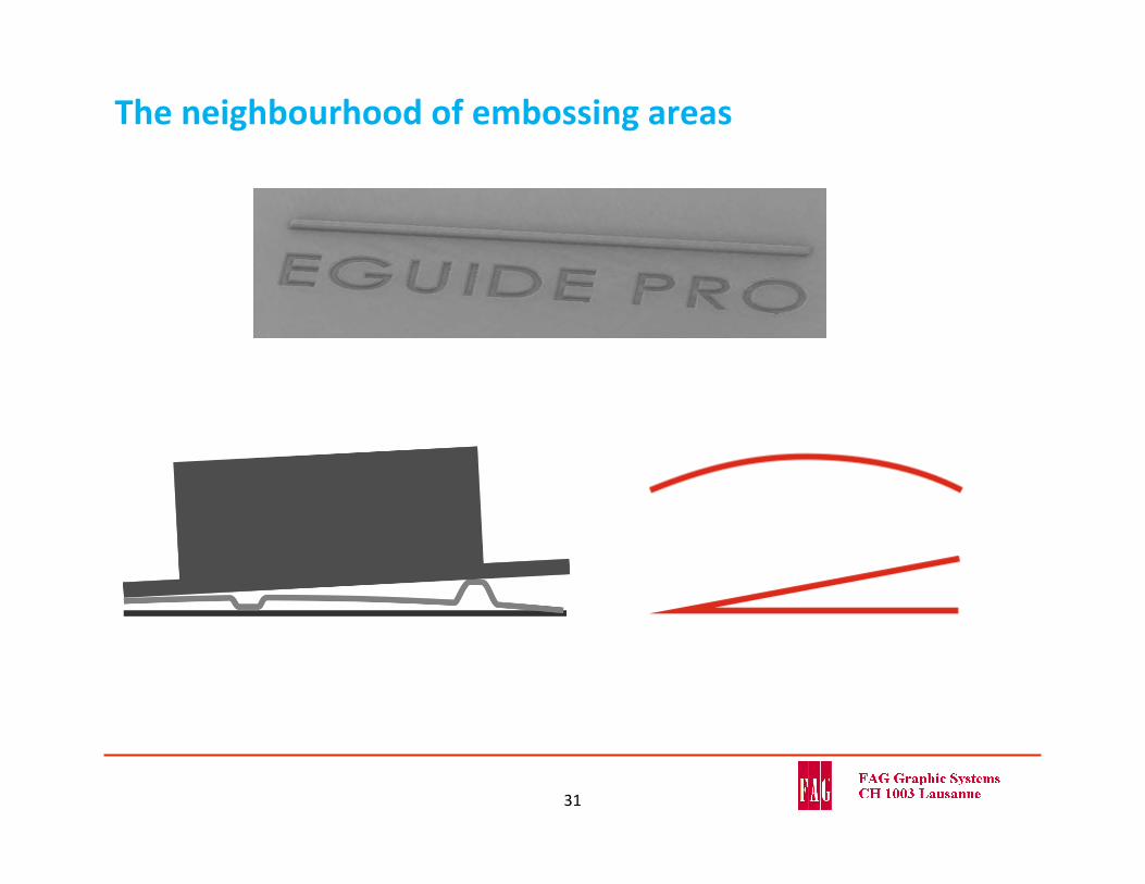
The neighbourhood of embossing areas
31
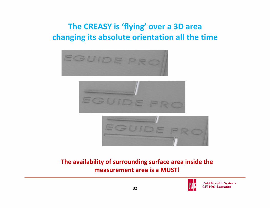
The CREASY is ‘flying’ over a 3D area changing its absolute orientation all the time
The availability of surrounding surface area inside the measurement area is a MUST!
32
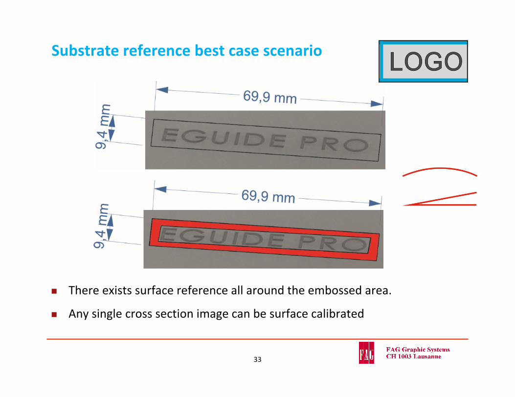
Substrate reference best case scenario
There exists surface reference all around the embossed area.
Any single cross section image can be surface calibrated
33
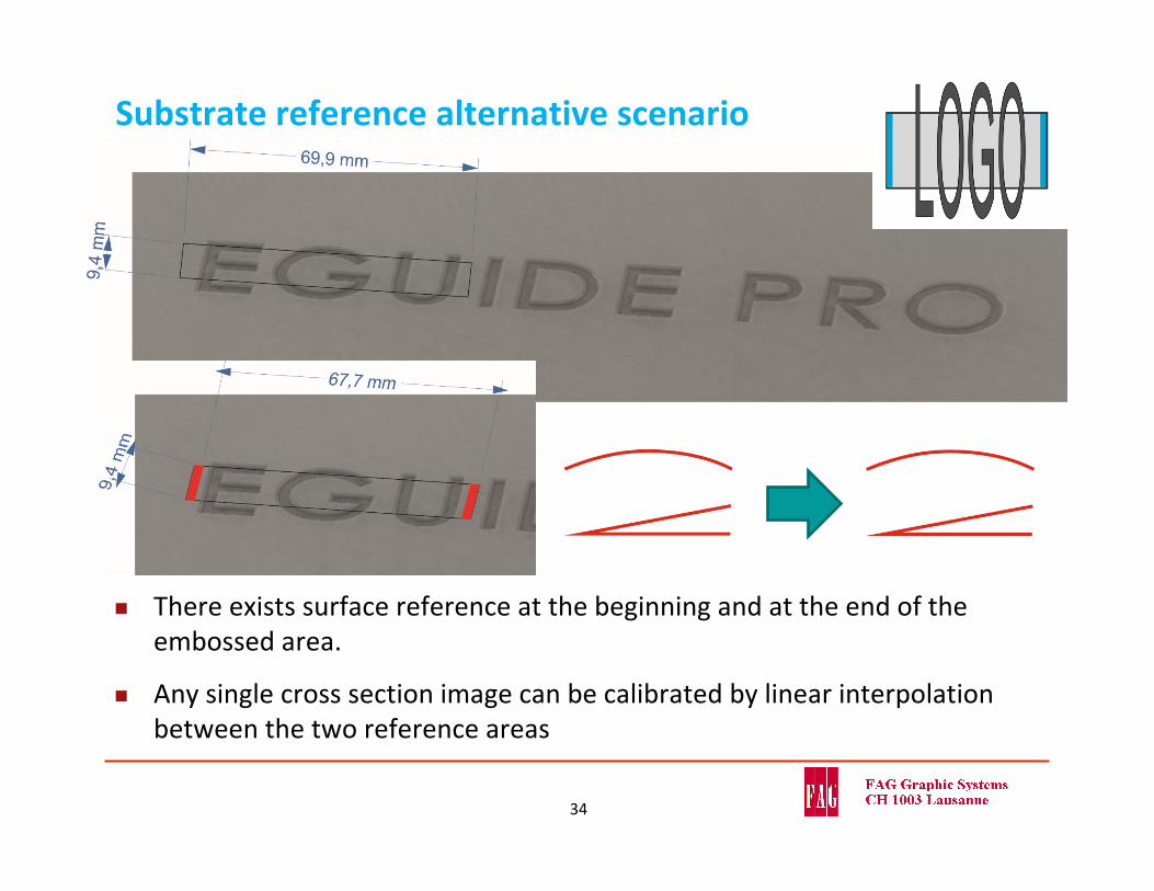
Substrate reference alternative scenario
There exists surface reference at the beginning and at the end of the embossed area.
Any single cross section image can be calibrated by linear interpolation between the two reference areas
34
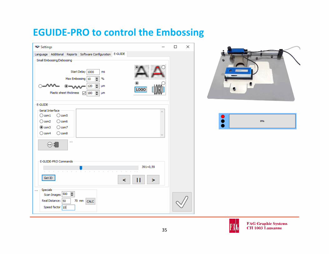
EGUIDE‐PRO to control the Embossing
35
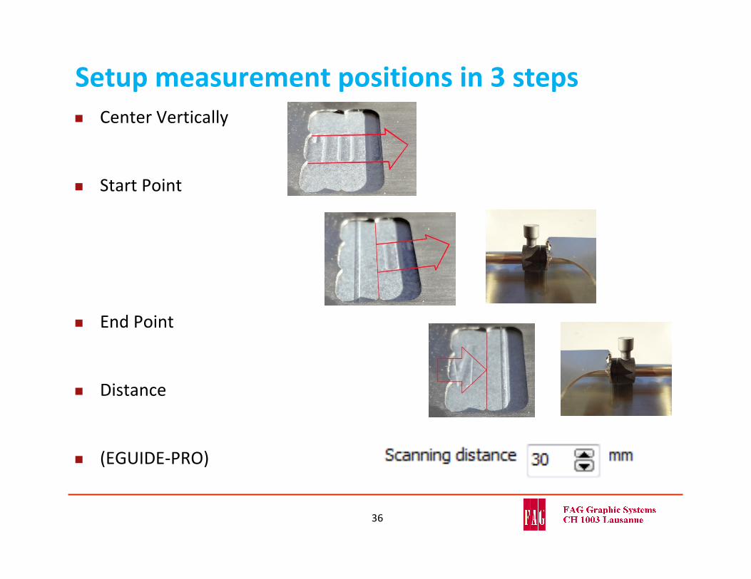
Setup measurement positions in 3 steps
36
Center Vertically
Start Point
End Point
Distance
(EGUIDE‐PRO)
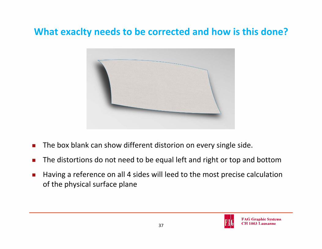
What exaclty needs to be corrected and how is this done?
The box blank can show different distorion on every single side.
The distortions do not need to be equal left and right or top and bottom
Having a reference on all 4 sides will leed to the most precise calculation of the physical surface plane
37
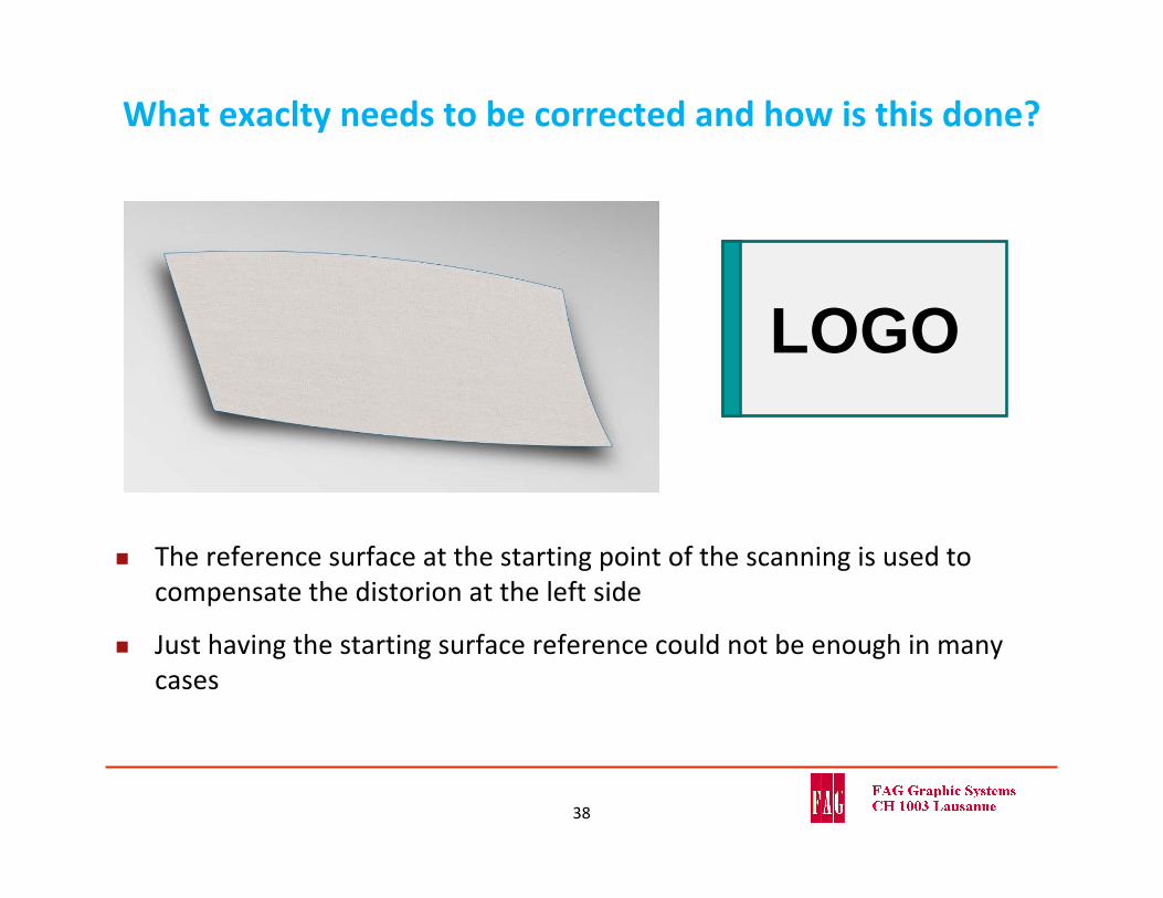
What exaclty needs to be corrected and how is this done?
The reference surface at the starting point of the scanning is used to compensate the distorion at the left side
Just having the starting surface reference could not be enough in many cases
38
LOGO
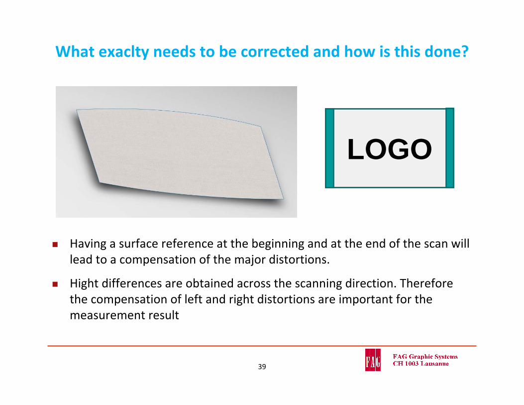
What exaclty needs to be corrected and how is this done?
Having a surface reference at the beginning and at the end of the scan will lead to a compensation of the major distortions.
Hight differences are obtained across the scanning direction. Therefore the compensation of left and right distortions are important for the measurement result
39
LOGO

What exaclty needs to be corrected and how is this done?
In case there is availlable surface reference all around the embossed area, the surface plane can be perfectly aligned to a flat plane.
40
LOGO
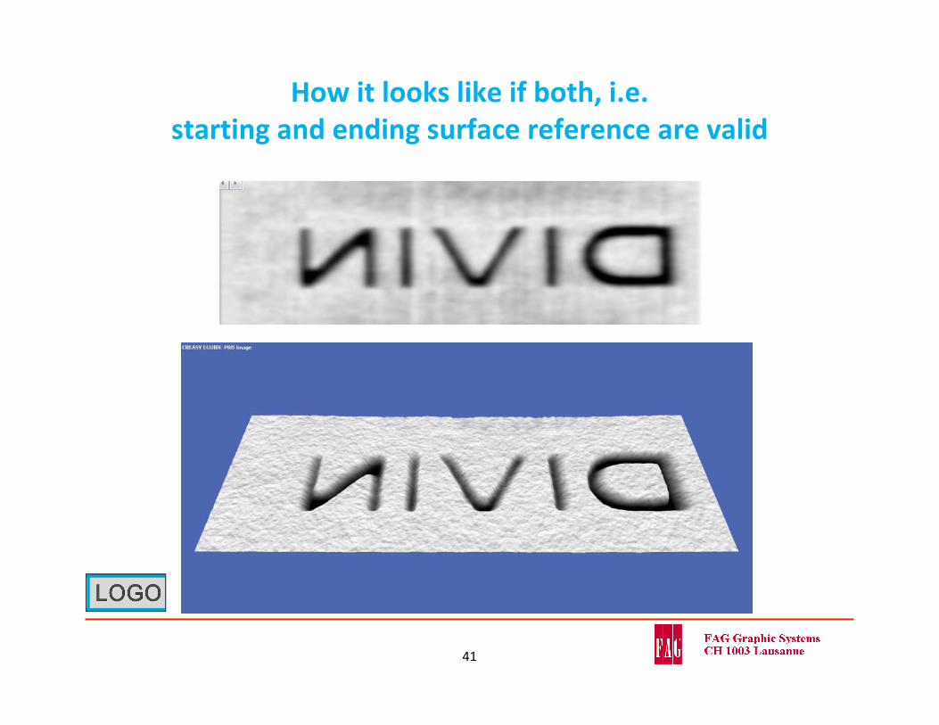
How it looks like if both, i.e. starting and ending surface reference are valid
41
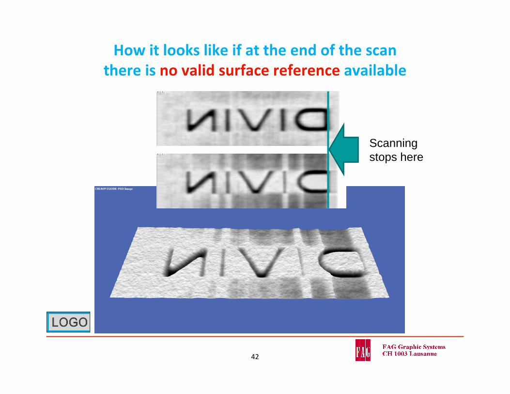
How it looks like if at the end of the scan there is no valid surface reference available
42
Scanning stops here
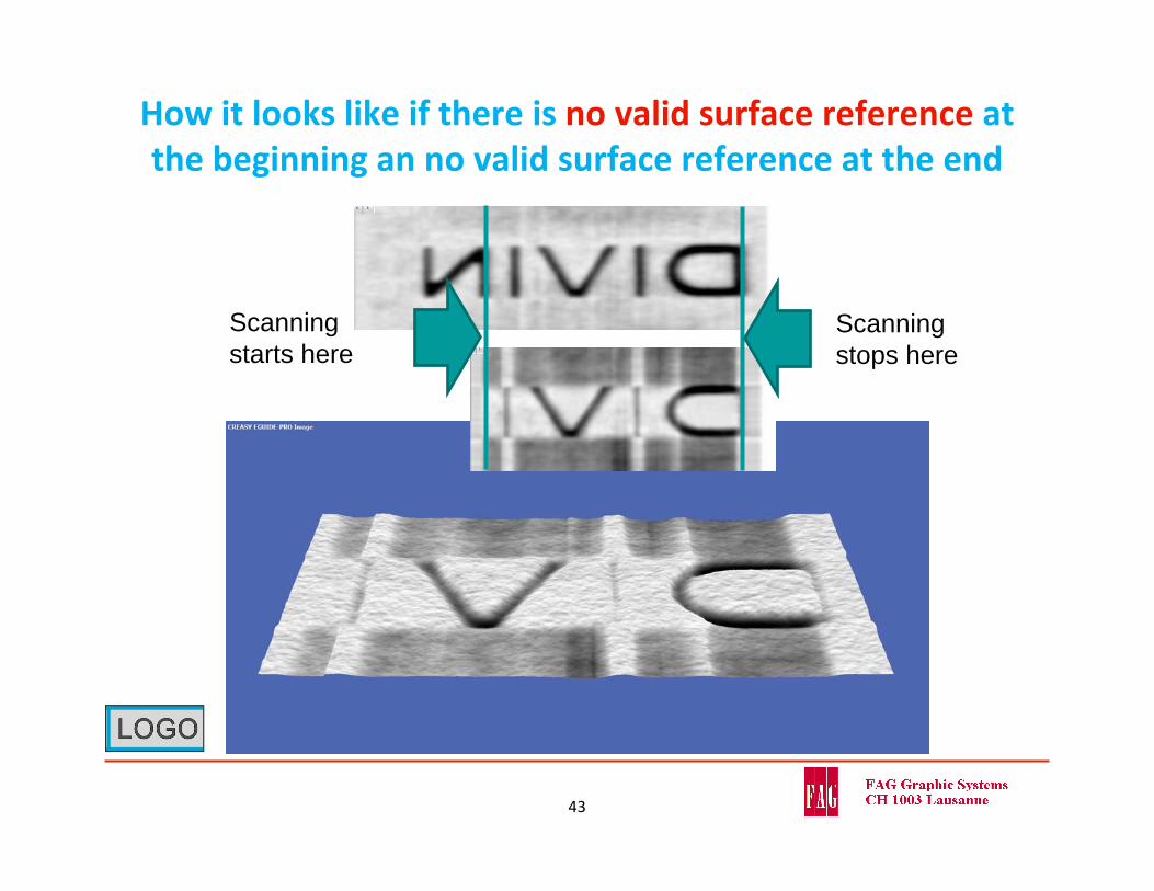
How it looks like if there is no valid surface reference at the beginning an no valid surface reference at the end
43
Scanning stops here
Scanning starts here
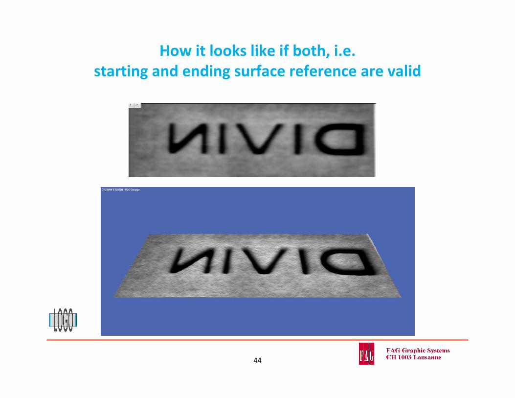
How it looks like if both, i.e. starting and ending surface reference are valid
44
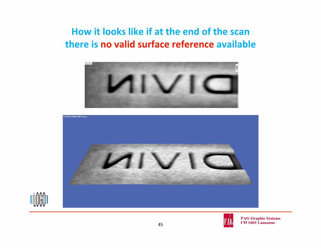
How it looks like if at the end of the scan there is no valid surface reference available
45
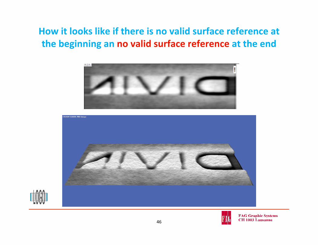
How it looks like if there is no valid surface reference at the beginning an no valid surface reference at the end
46
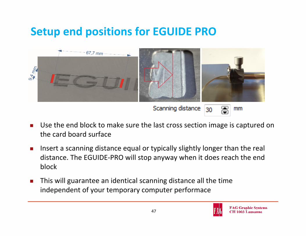
Setup end positions for EGUIDE PRO
47
Use the end block to make sure the last cross section image is captured on the card board surface
Insert a scanning distance equal or typically slightly longer than the real distance. The EGUIDE‐PRO will stop anyway when it does reach the end block
This will guarantee an identical scanning distance all the time independent of your temporary computer performace
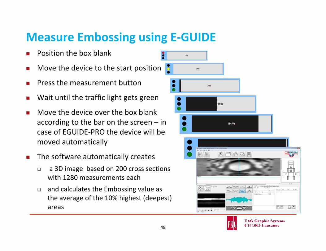
Measure Embossing using E‐GUIDE
48
Position the box blank
Move the device to the start position
Press the measurement button
Wait until the traffic light gets green
Move the device over the box blank according to the bar on the screen – in case of EGUIDE‐PRO the device will be moved automatically
The software automatically creates
a 3D image based on 200 cross sections with 1280 measurements each
and calculates the Embossing value as the average of the 10% highest (deepest) areas
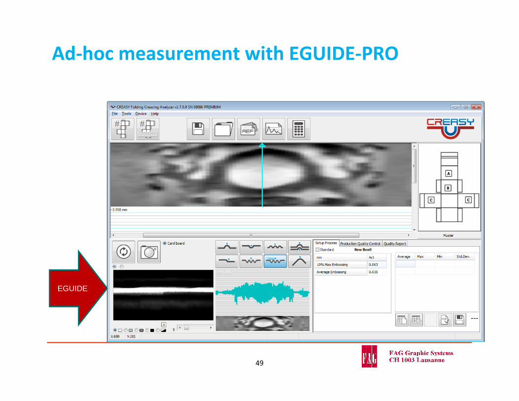
Ad‐hoc measurement with EGUIDE‐PRO
49
EGUIDE

Let‘s talk about card board surface
50
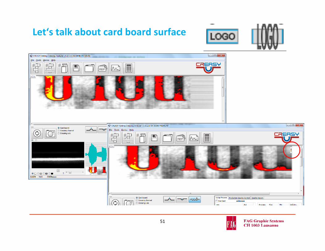
Let‘s talk about card board surface
51
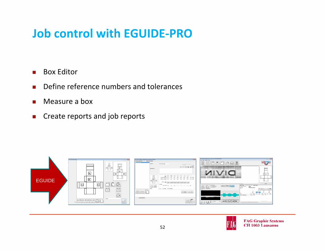
Job control with EGUIDE‐PRO
Box Editor
Define reference numbers and tolerances
Measure a box
Create reports and job reports
52
EGUIDE
Thank you…
See what happens
Understand why it happens
Take corrective actions
53