CRD c.8 Part-SPA - easa.europa.eu c.8 - CRST... · SPA.HHO.115 HHO communication .....69...
444
European Aviation Safety Agency R.F010-02 © European Aviation Safety Agency, 2010. All rights reserved. Proprietary document. COMMENT RESPONSE DOCUMENT (CRD) TO NOTICE OF PROPOSED AMENDMENT (NPA) 2009-02B for an Agency Opinion on a Commission Regulation establishing the Implementing Rules for air operations of Community operators and draft Decision of the Executive Director of the European Aviation Safety Agency on Acceptable Means of Compliance and Guidance Material related to the Implementing Rules for air operations of Community operators “Part-OPS” CRD c.8 – Comment Response Summary Table (CRST) Part-SPA 25 Nov 2010
Transcript of CRD c.8 Part-SPA - easa.europa.eu c.8 - CRST... · SPA.HHO.115 HHO communication .....69...
European Aviation Safety Agency
R.F010-02 © European Aviation Safety Agency, 2010. All rights reserved. Proprietary document.
COMMENT RESPONSE DOCUMENT (CRD)
TO NOTICE OF PROPOSED AMENDMENT (NPA) 2009-02B
for an Agency Opinion on a Commission Regulation establishing the Implementing
Rules for air operations of Community operators
and
draft Decision of the Executive Director of the European Aviation Safety Agency on
Acceptable Means of Compliance and Guidance Material related to the Implementing
Rules for air operations of Community operators
“Part-OPS”
CRD c.8 – Comment Response Summary Table (CRST) Part-SPA
25 Nov 2010

CRST Part-SPA
Page 2 of 444
Table of contents
Part-SPA | IR ........................................................................................................ 9
Subpart A - General requirements .................................................................... 9
SPA.GEN.100 Competent authority ...................................................... 9
SPA.GEN.105 Application for a specific approval ................................... 10
SPA.GEN.110 Privileges of an operator holding a specific approval .......... 12
SPA.GEN.115 Changes to operations subject to a specific approval ......... 13
SPA.GEN.120 Continued validity of a specific approval ........................... 14
Subpart B – Performance-based navigation operations (PBN) ....................... 15
SPA.PBN.100 PBN operations ............................................................. 15
SPA.PBN.105 PBN operational approval ............................................... 16
Subpart C – Operations with specified minimum navigation performance
(MNPS) ......................................................................................... 18
SPA.MNPS.100 MNPS operations ......................................................... 18
SPA.MNPS.105 MNPS operational approval ........................................... 18
Subpart D - Operations in airspace with reduced vertical separation minima
(RVSM) ......................................................................................... 20
SPA.RVSM.100 RVSM operations ......................................................... 20
SPA.RVSM.105 RVSM operational approval........................................... 20
SPA.RVSM.110 RVSM equipment requirements .................................... 21
SPA.RVSM.115 RVSM height-keeping errors ......................................... 22
Subpart E – Low visibility operations (LVO) ................................................... 23
OPS.SPA.001.LVO Low visibility operations (LVO) ................................. 24
OPS.SPA.010.LVO Aircraft requirements for LVO ................................... 25
OPS.SPA.020.LVO LVO operating minima ............................................. 25
OPS.SPA.030.LVO Flight crew requirements for LVO .............................. 28
Subpart F - Extended range operations with two-engined aeroplanes
(ETOPS) ........................................................................................ 28
SPA.ETOPS.100 ETOPS ...................................................................... 29
SPA.ETOPS.105 ETOPS operational approval aerodrome ........................ 29
SPA.ETOPS.110 ETOPS en-route alternate aerodrome ........................... 30
SPA.ETOPS.115 ETOPS en-route alternate aerodrome planning minima ... 30
Subpart G - Transport of dangerous goods .................................................... 31
25 Nov 2010

CRST Part-SPA
Page 3 of 444
SPA.DG.100 Approval to transport dangerous goods ............................. 31
SPA.DG.105 Dangerous goods information and documentation ............... 33
Subpart H– Helicopter operations with night vision imaging systems ............ 54
SPA.NVIS.100 Night vision imaging system (NVIS) operations ................ 54
SPA.NVIS.110 Equipment requirements for NVIS operations .................. 56
SPA.NVIS.120 NVIS operating minima ................................................. 60
SPA.NVIS.130 Crew requirements for NVIS operations .......................... 61
SPA.NVIS.140 Information and documentation ..................................... 63
Subpart I– Helicopter hoist operations ........................................................... 64
SPA.HHO.100 Helicopter hoist operations (HHO) ................................... 64
SPA.HHO.110 Equipment requirements for HHO ................................... 68
SPA.HHO.115 HHO communication ..................................................... 69
SPA.HHO.125 Performance requirements for HHO ................................ 70
SPA.HHO.130 Crew requirements for HHO .......................................... 71
SPA.HHO.135 HHO Passenger briefing ................................................. 73
SPA.HHO.140 Information and documentation ...................................... 74
Subpart J - Helicopter emergency medical service operations ........................ 74
SPA.HEMS.100 Helicopter emergency medical service
(HEMS)operations ............................................................................. 75
SPA.HEMS.110 Equipment requirements for HEMS operations ................ 78
SPA.HEMS.115 - Communication ........................................................ 79
SPA.HEMS.120 HEMS operating minima ............................................... 79
SPA.HEMS.125 Performance requirements for HEMS operations .............. 81
SPA.HEMS.130 Crew requirements ...................................................... 83
SPA.HEMS.135 HEMS medical passenger and other personnel briefing ..... 91
SPA.HEMS.140 Information and documentation .................................... 92
SPA.HEMS.145 HEMS operating base facilities ...................................... 93
SPA.HEMS.150 Fuel supply ................................................................ 94
SPA.HEMS.155Refuelling with passengers embarking, on board or
disembarking ................................................................................... 94
Part-SPA | AMC/GM ............................................................................................ 96
Subpart A- General requirements ................................................................... 96
AMC1-SPA.GEN.105(b)(4)Application for a specific approval ................... 96
DOCUMENTATION ................................................................................ 96
25 Nov 2010

CRST Part-SPA
Page 4 of 444
Subpart B – Performance-based navigation operations (PBN) ....................... 96
GM1-SPA.PBN.100 PBN operations ...................................................... 97
GENERAL ............................................................................................ 97
Subpart D - Operations in airspace with reduced vertical separation minima
(RVSM) ....................................................................................... 104
AMC1-SPA.RVSM.105 RVSM operational approval ............................... 106
CONTENT OF OPERATOR RVSM APPLICATION ........................................ 106
AMC2-SPA.RVSM.105 RVSM operational approval .............................. 108
OPERATING PROCEDURES .................................................................. 108
GM1-SPA.RVSM.105 RVSM operational approval ................................. 117
SPECIFIC REGIONAL PROCEDURES ...................................................... 117
AMC1-SPA.RVSM.110 RVSM equipment requirements .......................... 118
TWO INDEPENDENT ALTITUDE MEASUREMENT SYSTEMS ........................ 118
Subpart E – Low visibility operations (LVO) ................................................. 119
GM1 OPS.SPA.001.LVO Low visibility operations (LVO) ........................ 119
GENERAL – TERMINOLOGY .................................................................. 120
GM2 OPS.SPA.001.LVO Low visibility operations (LVO) ........................ 123
DOCUMENTS CONTAINING INFORMATION RELATED TO LOW VISIBILITY
OPERATIONS ..................................................................................... 123
AMC OPS.SPA.001.LVO(b)(1) Low visibility operations (LVO) ................ 124
FLIGHT CREW TRAINING .................................................................... 124
GM- OPS.SPA.001.LVO(b)(1) Low visibility operations (LVO) ................ 147
FLIGHT CREW TRAINING .................................................................... 147
AMC OPS.SPA.001.LVO(b)(2) Low visibility operations (LVO) ................ 148
USE OF ENHANCED VISION SYSTEMS (EVS) ......................................... 148
GM- OPS.SPA.001.LVO(b)(2) Low visibility operations (LVO) ................ 153
USE OF ENHANCED VISION SYSTEMS (EVS) ......................................... 153
AMC OPS.SPA.001.LVO(b)(2)(iii) Low visibility operations (LVO) ........... 157
NORMAL PROCEDURES ....................................................................... 158
GM1 OPS.SPA.001.LVO(b)(2)(iii) Low visibility operations (LVO) ........... 161
NORMAL PROCEDURES ....................................................................... 161
GM2 OPS.SPA.001.LVO(b)(2)(iii) Low visibility operations (LVO) ........... 162
NORMAL PROCEDURES – USE OF AUTOLAND SYSTEMS WHEN LOW
VISIBILITY PROCEDURES ARE NOT IN FORCE........................................ 162
AMC1 OPS.SPA.001.LVO(b)(3) Low visibility operations (LVO) .............. 168
25 Nov 2010

CRST Part-SPA
Page 5 of 444
OPERATIONAL DEMONSTRATION AND DATA COLLECTION/ANALYSIS ....... 168
AMC2 OPS.SPA.001.LVO(b)(3) Low visibility operations (LVO) .............. 181
OPERATIONAL DEMONSTRATION AND DATA COLLECTION/ANALYSIS ....... 182
GM- OPS.SPA.001.LVO(b)(3) Low visibility operations (LVO) ................ 185
CRITERIA FOR A SUCCESFUL CAT II/III APPROACH AND AUTOMATIC
LANDING .......................................................................................... 185
AMC1 OPS.SPA.020.LVO LVO operating minima .................................. 187
GENERAL .......................................................................................... 189
Appendix 1 to AMC1 OPS.SPA.020.LVO LVO operating minima ............. 191
LOWER THAN STANDARD CAT I OPERATIONS ....................................... 191
Appendix 2 to AMC1 OPS.SPA.020.LVO LVO operating minima ............. 196
CAT II AND OTHER THAN STANDARD CAT II OPERATIONS ...................... 196
Appendix 3 to AMC1 OPS.SPA.020.LVO LVO operating minima ............. 203
PRECISION APPROACH - CAT III OPERATIONS ...................................... 203
Appendix 4 to AMC1 OPS.SPA.020.LVO LVO operating minima ............. 207
AERODROME MINIMA – TAKE-OFF MINIMA ........................................... 207
GM1 Appendix 3 to AMC1 OPS.SPA.020.LVO LVO operating minima ...... 207
CREW ACTIONS IN CASE OF AUTOPILOT FAILURE AT OR BELOW
DECISION HEIGHT IN FAIL-PASSIVE CATEGORY III OPERATIONS ............ 208
GM2 Appendix 3 to AMC1 OPS.SPA.020.LVO LVO operating minima ...... 208
ESTABLISHMENT OF MINIMUM RVR FOR CATEGORY II AND III
OPERATIONS ..................................................................................... 208
AMC2 OPS.SPA.020.LVO LVO operating minima .................................. 216
EFFECT ON LANDING MINIMA OF TEMPORARILY FAILED OR
DOWNGRADED GROUND EQUIPMENT ................................................... 216
Subpart G - Transport of dangerous goods ................................................... 220
AMC1-SPA.DG.100(b)(1) Approval to transport dangerous goods .......... 220
TRAINING PROGRAMME ...................................................................... 220
AMC1-SPA.DG.100(b)(2)(ii) Approval to transport dangerous goods...... 223
ACCEPTANCE OF DANGEROUS GOODS ................................................. 223
AMC1-SPA.DG.100(b)(2)(iv) Approval to transport dangerous goods ..... 224
PROVISION OF INFORMATION IN THE EVENT OF AN IN-FLIGHT
EMERGENCY ...................................................................................... 224
GM1-SPA.DG.100(b)(1) Approval to transport dangerous goods ........... 228
PERSONNEL ...................................................................................... 228
25 Nov 2010

CRST Part-SPA
Page 6 of 444
AMC1-SPA.DG.105(a) Dangerous goods information and
documentation ............................................................................... 229
INFORMATION TO THE PILOT-IN-COMMAND/COMMANDER ...................... 229
Subpart H – Helicopter operations with night vision imaging systems ......... 293
GM1-SPA.NVIS.110(f) Equipment requirements for NVIS operations ..... 295
MODIFICATION OR MAINTENANCE TO THE HELICOPTER ......................... 295
GM1-SPA.NVIS.130 Crew requirements for NVIS operations ................. 296
UNDERLYING ACTIVITY ...................................................................... 296
GM1-SPA.NVIS.130(e)Crew requirements for NVIS operations ............. 296
OPERATIONAL APPROVAL ................................................................... 296
AMC1- SPA.NVIS.130(f)(1) Crew requirements for NVIS operations ...... 297
TRAINING AND CHECKING SYLLABUS................................................... 297
AMC1-SPA.NVIS.130(f)Crew requirements ......................................... 299
CHECKING OF NVIS CREW MEMBERS ................................................... 299
GM1-SPA.NVIS.130(f)Crew requirements ........................................... 300
TRAINING GUIDELINES AND CONSIDERATIONS .................................... 300
GM2-SPA.NVIS.130(f)Crew requirements ........................................... 308
INSTRUCTION - GROUND TRAINING AREAS OF INSTRUCTION ................ 308
GM3-SPA.NVIS.130(f)Crew requirements ........................................... 320
FLIGHT TRAINING - AREAS OF INSTRUCTION........................................ 320
GM4-SPA.NVIS.130(f)Crew requirements ........................................... 322
NVIS PRE-FLIGHT BRIEFING/CHECKLIST .............................................. 322
AMC1-SPA.NVIS.140 Information and documentation .......................... 328
OPERATIONS MANUAL ........................................................................ 328
GM1-SPA.NVIS.140 Information and documentation ........................... 329
CONCEPT OF OPERATIONS .................................................................. 329
Subpart I – Helicopter hoist operations ............................................................ 388
AMC1-SPA.HHO.130(a)(2) Crew requirements for HHO ....................... 391
RELEVANT EXPERIENCE ...................................................................... 391
AMC1-SPA.HHO.130(a)(5) Crew requirements for HHO ....................... 395
CRITERIA FOR TWO PILOT HHO .......................................................... 395
AMC1-SPA.HHO.110(a) Equipment requirements for HHO .................... 397
AIRWORTHINESS APPROVAL FOR HUMAN EXTERNAL CARGO .................. 397
AMC1-SPA.HHO.130(f)(1) Crew requirements for HHO ........................ 400
TRAINING AND CHECKING SYLLABUS................................................... 400
25 Nov 2010

CRST Part-SPA
Page 7 of 444
AMC1-SPA.HHO.140 Information and documentation .......................... 402
OPERATIONS MANUAL ........................................................................ 402
Subpart J - Helicopter emergency medical service operations .......................... 403
GM1-SPA.HEMS.100(a) Helicopter emergency medical service
(HEMS)operations .......................................................................... 403
THE HEMS PHILOSOPHY ..................................................................... 403
AMC1-SPA.HEMS.130(a)(2) Crew requirements for HEMS operations .... 415
EXPERIENCE ..................................................................................... 415
AMC1-SPA.HEMS.130(a)(4) Crew requirements for HEMS operations .... 416
RECENCY .......................................................................................... 416
AMC1-SPA.HEMS.130(e)(2) (ii)(B)Crew requirements for HEMS
operations ..................................................................................... 425
FLIGHT FOLLOWING SYSTEM .............................................................. 425
AMC1-SPA.HEMS.130(e)Crew requirements for HEMS operations .......... 425
HEMS TECHNICAL CREW MEMBER ........................................................ 425
GM1-SPA.HEMS.120 HEMS Operating Minima ..................................... 428
REDUCED VISIBILITY ......................................................................... 429
GM1-SPA.HEMS.125 (b)(2) Performance requirements for HEMS
operations ..................................................................................... 430
PERFORMANCE CLASS 2 OPERATIONS AT A HEMS OPERATING SITE ........ 430
AMC1-SPA.HEMS.125(b)(3) Performance requirements for HEMS
operations ..................................................................................... 430
HEMS OPERATING SITE DIMENSIONS .................................................. 430
GM1-SPA.HEMS.130(e)(2)(ii) Crew requirements for HEMS operations .. 432
SPECIFIC GEOGRAPHICAL AREAS ........................................................ 432
AMC1-SPA.HEMS.130(f)(1) Crew requirements for HEMS operations ..... 433
TRAINING AND CHECKING SYLLABUS................................................... 433
AMC1-SPA.HEMS.130(f)(2)(ii)(B) Crew requirements for HEMS
operations ..................................................................................... 435
LINE CHECKS .................................................................................... 436
AMC1-SPA.HEMS.135(a) HEMS medical passenger and other personnel
briefing .......................................................................................... 436
HEMS MEDICAL PASSENGER BRIEFING ................................................. 436
AMC2-SPA.HEMS.135(a) HEMS medical passenger and other personnel
briefing .......................................................................................... 437
HEMS MEDICAL PASSENGER BRIEFING ................................................. 437
25 Nov 2010

CRST Part-SPA
Page 8 of 444
AMC1-SPA.HEMS.135(b)HEMS medical passenger and other personnel
briefing .......................................................................................... 437
GROUND EMERGENCY SERVICE PERSONNEL ......................................... 437
AMC1-SPA.HEMS.140 Information and documentation ......................... 438
OPERATIONS MANUAL ........................................................................ 438
25 Nov 2010

CRST Part-SPA
Page 9 of 444
A: Rule B: Summary of comments C: Reasons for change,
remarks
Part-SPA | IR
Subpart A - D - Section I - General rRequirements
SPA.GEN.100OPS.SPA.001.GEN Competent authority 1/ wording of the title is not
accepted.
1/ Rule title kept but because
the rule content now better
reflects the rule title.
(a) The authority issuing a specific approval shall be:
(1) for commercial operators the competent authority
issuing the air operator certificate (AOC); and
(2) for non-commercial operators the competent
authority of the State in which the operators are
established or residing.
(b) Notwithstanding (a)(2) above, for non-commercial
operators using aircraft registered in a third country, the
requirements for the approval for operations in
performance based navigation(PBN), minimum
operational performance specifications (MNPS) and
reduced vertical separation minima(RVSM) airspace shall
not apply if these approvals are issued by a third country
State of Registry.
Notwithstanding OPS.GEN.005, for the purpose of this Subpart, the
1/ by referring only to the State of
Registry there can be no Member
State competent authority for
cases of the operation of aircraft
covered by Article 4(1)(c) of
Regulation 216/2008.
1/ Changes proposed to clarify
that for non-commercial
operators those approvals
mentioned in ICAO Annex 6 Part
II are issued by the State of
Registry. For a 4(1)(c) operator,
this would be the non-European
Sate of Registry.
25 Nov 2010

CRST Part-SPA
Page 10 of 444
A: Rule B: Summary of comments C: Reasons for change,
remarks
competent authority for non-commercial operators conducting
operations in PBN/MNPS and RVSM airspace shall be the State
of registry.
OPS.SPA.005.GEN Scope 1/ The reference to OPS.GEN.005
is not understood. It may be that
OPS.GEN.001 is meant but, if so,
there is no distinction between
non-commercial operators of
complex and those of non-complex
aircraft as in that requirement.
1/ Deleted, because the scope
and applicability is addressed in
the Cover Regulation for Air
Operations.
This part establishes the requirements to be met by an operator to
qualify for the issue or continuation of specific operational approvals.
SPA.GEN.105OPS.SPA.020.GEN Application for a specific
approval
(a) Applicants for the initial issue of a specific approval shall
provide the competent authority with the documentation
required by in the applicable subpart Subpart, together with
and the following information:
(1) Tthe official name and/or business name, address and
mailing address of the applicant; and
1/ It has to be open for a private
pilot/owner to apply too.
1/ Text amended accordingly.
25 Nov 2010

CRST Part-SPA
Page 11 of 444
A: Rule B: Summary of comments C: Reasons for change,
remarks
(2) Aa description of the intended operation.
(b) Without prejudice to OR.GEN.015, aApplicants for a specific
approval shall provide the following evidence demonstrate
to the competent authority that:
(1) they comply compliance with the requirements of the
applicable sectionSubpart;
(2) that the aircraft and required equipment comply with
fulfil the applicable airworthiness requirements in
accordance with Regulation (EC) No 1702/2003 and
are approved when required by the relevant
Subpart/approvals;
1/ Text proposal: “comply with the
applicable airworthiness
requirements and are approved
when required by the relevant
section /approvals”
1/ Text revised accordingly.
(3) that a training programme has been established for flight
crew and, as applicable, other personnel involved in these
operations; and
1/ Due to the type of operations of
our company (test and ferry
flights) and taking into
consideration the wide variety of
aircraft operated by our company,
the different equipment fits for
each of those aircraft, the extreme
short period of time those aircraft
are operated, and the fact that the
majority of our crews are employed
on a contract per flight basis,
requiring an operator training
1/ This is not a question of
practicable or not but a safety
requirement. As such it is also
applicable to operators
specialised in ferry flights.
25 Nov 2010

CRST Part-SPA
Page 12 of 444
A: Rule B: Summary of comments C: Reasons for change,
remarks
programme is not practicable.
(4) that operating procedures in accordance with the
applicable subpartSubpart have been documented;
andspecified in the operations manual.
(5) that the relevant elements defined in the
operational suitability data (OSD) established in
accordance with Part-21 are taken into account.
1/ The content of AMC
OPS.SPA.020.GEN (b)(4) should be
transferred to this paragraph.
1/ AMC1-SPA.GEN.105(b)(4)
should be kept.
(5) has been included to provide
a link with the OSD.
(c) Operators shall retain rRecords relating to the requirements
of (a) and (b) above shall be retained by the operator at least
for the duration of the operation requiring a specific
approval, or, if applicable, in accordance with
OR.OPS.MLR.220.MLR.
1/ OR OPS is not applicable to
NCO. It is preferable to write
directly the requirement: “(c)
Records relating to the
requirements of (a) and (b) above
shall be retained by the operator in
accordance with OR.OPS.220.MLR
at least for the duration of the SPA
operation.
2/ Why is this 5 years. - Why not 3
- or for the duration of the
approval?
1/ Text revised accordingly.
2/ It is the intention to use
OR.OPS.MLR for all records. For
NCO, OR.OPS does not apply,
therefore the amended text.
SPA.GEN.110OPS.SPA.025.GEN Privileges of an operator
holding a specific approval
25 Nov 2010

CRST Part-SPA
Page 13 of 444
A: Rule B: Summary of comments C: Reasons for change,
remarks
The scope of the activity that the operator is approved to conduct
shall be specified in the operations manualdocumented and
specified:
(a) for non-commercial operators in approval certificate the
list of specific approvals; orand,
(b) for commercial operators, in the operations specifications to the
air operator certificateAOC.
1/ Add after “operations manual”:
“when required by Annex IV to
Regulation (EC) No 216/2008
(Essential requirements for air
operations), or in a procedures
manual”.
1/ Already addressed in AMC1-
SPA.GEN.105(b)(4).
The addition of “List of specific
approvals” aligns with AR.OPS.
SPA.GEN.115OPS.SPA.030.GEN Changes to operations subject
to a specific approval
(a) When the conditions of a specific approval are affected
by changes, The operators shall provide the relevant
documentation to the competent authority and obtain prior
approval for the operation.notify the competent authority of any
change on the items listed in OPS.SPA.020.GEN (a) and (b) and any
of the requirements in the applicable section before such change
takes place.
1/ Text proposal: The operator
shall notify the competent
authority of any change on the
items listed in OPS.SPA.020.GEN
(a) and (b) and any other change
affecting of the requirements in the
applicable section of this Subpart,
before such changes takes place.
2/ Amend a) to read as „The
operator shall notify the competent
Authority of any change that
affects the conditions of the
approval‟
1-2/ Text revised as an prior
approval item.
25 Nov 2010
CRST Part-SPA
Page 14 of 444
A: Rule B: Summary of comments C: Reasons for change,
remarks
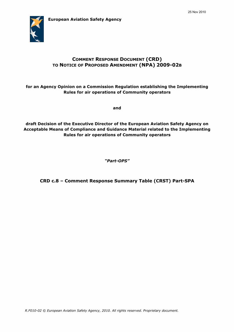
(b) The competent authority may prescribe the conditions under
which the organisation may operate during such changes,
unless the competent authority determines that the specific
approval shall be suspended or revoked.
Rule deleted because it is
already addressed above.
(c) In the case of a change to a specific approval, operators shall
provide the competent authority with the relevant parts of the
operations manual and all other relevant documentation.
Rule deleted because it is
already addressed above.
SPA.GEN.120OPS.SPA.035.GEN Continued vValidity of a
specific approval
1/ Non-CAT operator specific
approvals shall be renewed at least
every 3 years by the competent
authority.
2/ Proposed text: Recommend
inclusion of the following text - A
specific approval will be issued for
a specified time frame to include a
commencement and expiry date.
1-2/ The limited duration would
not be needed in the proposed
oversight mechanisms for non-
commercial and commercial
operators.
Specific approvals shall be issued for an unlimited duration .
Theyand shall remain valid subject to the operator remaining in
compliance with the requirements associated with the specific
approval this subpartand taking into account the relevant
elements defined in the OSD established in accordance with
Part-21.,OR.GEN.030, OR.GEN.035 (a)(1),(b) and (c).
Text added to provide a link to
the OSD.
25 Nov 2010

CRST Part-SPA
Page 15 of 444
A: Rule B: Summary of comments C: Reasons for change,
remarks
Section II - Operations in areas with specified navigation
performanceSubpart B – Performance-based navigation
operations (PBN)
1/ Acronym "MNPS" should be
introduced just after "minimum
navigation performance
specifications" in order to
understand the use of this acronym
further in the text.
2/ This mixes up two different
types of airspace: that which
comes under “Performance Based
Navigation” (PBN) as defined in
ICAO DOC 9613 and “Minimum
Navigation Performance
Specification Airspace” (MNPS),
which is not PBN and applies just
to the North Atlantic.
1-2/ PBN and MNPS have been
split into two Subparts. The
term SPN is not used anymore.
SPA.PBN.100 PBN operationsOPS.SPA.001.SPN Operations in
areas with specified performance based navigation (SPN)
(a) An aircraft shall only be operated in designated airspace, on
routes or in accordance with procedures where performance-based
navigation (PBN)navigation specifications are established, if the
operator has been granted an approval approved by the
competent authority to conduct such operations. No specific
approval is required for operations in area navigation 5
(RNAV5 (basic navigation, B-RNAV)) designated airspace.
1/ § (b): The sentence is not
understandable: it seems that
some words are missing when
introducing the part "minimum
navigation performance
specifications are established".
Moreover the acronym "MNPS"
should be introduced just after
"minimum navigation performance
specifications" in order to
understand the use of this acronym
1/ (b) is now contained in
SPA.MNPS.100
2-3/ B-RNAV has been excluded
from the approval. For the
remaining PBN operations, a
self-declaration is not intended.
4/ GM1-SPA.PBN.100 PBN
provides further information.
25 Nov 2010

CRST Part-SPA
Page 16 of 444
A: Rule B: Summary of comments C: Reasons for change,
remarks
GM1-SPA.PBN.100 PBN operations
(b) An aircraft shall only be operated in designated airspace, based
on ICAO Regional Air Navigation Agreement, minimum
navigation performance specifications are established, if the
operator has been approved by the competent authority
further in the text.
2/ This section does not permit
self-declared compliance for private
operations based on meeting
installation, database, operational
and pilot training criteria. We
believe it should. This has been the
case successfully for B-RNAV in
Europe and RNP-1 in the USA.
3/ An RNAV (GPS) approach and
en-route navigation with LNAV
(BRNAV) is less complex/critical
compared to flying a VOR/NDB
approach and navigating along an
airway established by VOR/NDB. It
does not justify the additional
administrative burden for a special
approval
4/ define which navigation
specifications and type of
approaches are possible without
any SPA.
SPA.PBN.105 PBN operational approval
(c) To obtain an PBN operational such approval by from the
1/ Delete the reference to
„experience requirements‟.
2/ 3) (vi) specific regional
1/ Not accepted. Experience
requirements are relevant.
2-3/ Text revised accordingly.
25 Nov 2010

CRST Part-SPA
Page 17 of 444
A: Rule B: Summary of comments C: Reasons for change,
remarks
competent authority, the operator shall provide evidence that:
(1a) demonstrate that the relevant airworthiness approval of the
RNAV system has been obtainednavigation equipment meets
the required performance in terms of navigation functionality,
accuracy, integrity, availability and continuity;
(2b) establish and maintain a training programme for the flight crew
involved in these operations has been established; and
(3c) establish operating procedures have been established
specifying:
(i1) the equipment to be carried, including its operating
limitations and appropriate entries in the Mminimum
Eequipment Llist (MEL);
(ii2) flight crew composition and experience requirements;
(iii3) normal procedures;
(iv4) contingency procedures;
(v5) monitoring and incident reporting;(vi) specific
regional operating procedures, in case of MNPS; and
(vii6)electronic navigation data managementnavigation
database integrity, in case of PBN.
operating procedures in case of
MNPS Comment: The requirement
does not only apply to MNPS.
Proposal: Delete the reference to
MNPS.
3/ Navigation Database Integrity is
not a matter of operating
procedures.
4/ The content of operating
procedures should be defined in
the corresponding AMC 20
material.
Proposal: Define the content of the
operating procedures in the AMC
20 material
5/ (c)(3): operating procedures
should be as detailed as in
OPS.SPA.001.RVSM (b)(2)
6/ Single private non-commercial
aircraft-owner or a small aero-
c1ub: these requirements are not
feasible and impracticable to
achieve. It has to be the pilot's
responsibility to keep currency.
4/ The AMC 20 material should
deal with those procedures
common to all operators, and
not attempt to cover all possible
types of operation
5/ The IR slightly differ from the
corresponding rule in Subpart
SPA.RVSM due to the different
AMC material attached to this
IR.
6/ These rules apply to any
operator planning to conduct
PBN operations (except B-
RNAV). However, the Authority
is bound to apply a
proportionate approach.
25 Nov 2010

CRST Part-SPA
Page 18 of 444
A: Rule B: Summary of comments C: Reasons for change,
remarks
Subpart C – Operations with specified minimum navigation
performance (MNPS)
PBN and MNPS have been split
into two Subparts.
SPA.MNPS.100 MNPS operations
Aircraft shall only be operated in designated minimum
navigation performance specifications (MNPS) airspace in
accordance with Regional Supplementary Procedures, where
minimum navigation performance specifications are
established, if the operator has been granted an approval by
the competent authority to conduct such operations.
SPA.MNPS.105 MNPS operational approvalOPS.SPA.010.SPN
Equipment requirements for operations in MNPS areas
To obtain an MNPS operational approval from the competent
authority, the operator shall provide evidence that:
(a) An aircraft conducting MNPS operations shall be equipped with
navigation equipment that complies with the ICAO Regional Air
Navigation Agreement.the navigation equipment meets the
required performance;
(b) Navigation navigation equipment display, indicators and
controls shall be are visible and operable by either pilot
seated at his/her duty station;.
(c) a training programme for the flight crew involved in
1/ Suggested new text:(b)
Navigation display, indicators and
flight crew controls shall be visible
and operable by either flight crew
member seated at his/her duty
station. Comment/suggestion:
Navigation equipment would
indicate the whole equipment of
which many parts are not visible to
the flight crew.
1/ Text amended accordingly.
Text aligned with the text for
SPA.PBN.
25 Nov 2010

CRST Part-SPA
Page 19 of 444
A: Rule B: Summary of comments C: Reasons for change,
remarks
these operations has been established; and
(d) operating procedures have been established specifying:
(1) the equipment to be carried, including its operating
limitations and appropriate entries in the minimum
equipment list (MEL);
(2) flight crew composition and experience
requirements;
(3) normal procedures;
(4) contingency procedures including those specified by
the authority responsible for the airspace
concerned; and
(5) monitoring and incident reporting.
OPS.SPA.030.SPN Flight crew requirements for operations in
PBN or MNPS areas
For commercial air transport operations the minimum flight crew
shall consist of at least two pilots.
1/ This way single pilot aircraft are
excluded. This is not correct.
2/ RNAV (GNSS) approaches (also
known as RNP(APCH) with PBN
terminology) are authorised even
with single pilot.
3/ What if a HEMS helicopter is
certified for SP IFR? This rule would
stop the introduction of IFR in
HEMS operation.
1-3/ Text deleted because flight
crew composition requirements
are to be found in OR.OPS.FC.
25 Nov 2010

CRST Part-SPA
Page 20 of 444
A: Rule B: Summary of comments C: Reasons for change,
remarks
Subpart D - Operations in airspace with reduced vertical
separation minima (RVSM)
SPA.RVSM.100 RVSM operationsOPS.SPA.001.RVSM
Operations in airspace with reduced vertical separation
minima (RVSM)
(a) An aAircraft shall only be operated in designated airspace
where a reduced vertical separation minimum of 300 m (1 000 ft)
applies above between flight level (FL) 290 and FL 410, inclusive, if :
(1) the aircraft has been issued with an RVSM airworthiness
approval by the Agency in accordance with Part-21; and
(2) the operator has been granted an approval approved by the
competent authority to conduct such operations.
1/ RVSM can be applied between
FL290 and FL410 inclusive in
accordance with ICAO.
1/ Text revised accordingly.
SPA.RVSM.105 RVSM operational approval
(b) To obtain such an RVSM operational approval by from the
competent authority, the operator shall provide evidence that:
(a) the RVSM airworthiness approval has been obtained;
(b) procedures for monitoring and reporting height-keeping errors
have been established;
(1c) establish and maintain a training programme for the flight crew
involved in these operations has been established; and
1/ Delete the reference to
„experience requirements‟.
2/ The maintenance programme
should be deleted from the list of
the operating procedures items.
3/ Single private non-commercial
aircraft-owner or a small aero-
1/ Not accepted. Experience
requirements are relevant.
2/ Text revised accordingly.
3/ These rules apply to any
operator planning to flight in
RVSM airspace. However, the
Authority is bound to apply a
25 Nov 2010

CRST Part-SPA
Page 21 of 444
A: Rule B: Summary of comments C: Reasons for change,
remarks
(d2) establish operating procedures have been established
specifying:
(1i) the equipment to be carried, including its operating
limitations and appropriate entries in the minimum
equipment list (MEL);
(ii2) flight crew composition and experience requirements;
(iii3) flight planning;
(iv4) pre-flight procedures;
(v5) procedures prior to RVSM airspace entry;
(vi6i)in-flight procedures;
(vii7)post-flight procedures;
(viii) maintenance programme;
(ix8) incident reporting; and
(9x) specific regional operating procedures.
AMC1-SPA.RVSM.105 RVSM operational approval
AMC2-SPA.RVSM.105 RVSM operational approval
GM1-SPA.RVSM.105 RVSM operational approval
c1ub: these requirements are not
feasible and impracticable to
achieve. It has to be the pilot's
responsibility to keep currency.
4/ Our operations may involve
flights that remain outside EU
airspace, and are with aircraft
registered in non-EASA Member
States. To obtain RVSM
airworthiness approvals in
accordance with Part-21 for each of
those individual aircraft is not
practicable.
proportionate approach.
4/ Part-21 has been deleted.
Regulation 1702/2003 already
contains all relevant
requirements.
“viii maintenance programme”
deleted, because it needs to be
addressed by airworthiness
requirements.
SPA.RVSM.110OPS.SPA.010.RVSM RVSM eEquipment
requirements for operations in RVSM airspace
25 Nov 2010

CRST Part-SPA
Page 22 of 444
A: Rule B: Summary of comments C: Reasons for change,
remarks
(a) In addition to the equipment required by OPS.GENother
Parts, aircraft used for operations in RVSM airspace shall be
equipped with:
(a1) two independent altitude measurement systems;
(b2) an altitude alerting system;
(c3) an automatic altitude control system; and
(d4) a secondary surveillance radar (SSR) transponder with altitude
reporting system that can be connected to the altitude
measurement system in use for altitude control.
AMC1-SPA.RVSM.110 RVSM equipment requirements
SPA.RVSM.115 RVSM height-keeping errors Text moved from AMC to IR.
(a) Operators shall report recorded or communicated occurrences
of height keeping height-keeping errors caused by
malfunction of aircraft equipment or of operational nature,
equal to or greater than:
(1) a total vertical error (TVE) of ±90 m (±300 ft);,
(2) an altimetry system error (ASE) of ±75 m (±245 ft);, and
(3) an assigned altitude deviation (AAD) of ±90 m (±300 ft).
(b) Reports of such occurrences shall be sent to the competent
authority within 72 hours. Reports shall include an initial
analysis of causal factors and measures taken to prevent repeat
25 Nov 2010

CRST Part-SPA
Page 23 of 444
A: Rule B: Summary of comments C: Reasons for change,
remarks
occurrences.
(bc) When height-keeping errors are recorded or received, the
operator shall take immediate action to rectify the conditions
that caused the errors and provide follow-up reports, if
requested by the competent authority.
OPS.SPA.030.RVSM Flight crew requirements for operations
in RVSM airspace
For commercial air transport operations the minimum flight crew
shall consist of at least two pilots.
Text deleted because flight crew
composition requirements are to
be found in OR.OPS.FC.
Subpart E – Low visibility operations (LVO) The revised text is displayed in
Subpart E – revised rule text.
Section IV – Low visibility operations 1/ It is suggested that the IRs in
Subpart SPA.LVO are revisited to
decide whether the functional
grouping of the rules is as logical
as it was in the original text, EU-
OPS and JAR-OPS 3.
2/ For a single private non-
commercial aircraft-owner or a
small air-club these requirements
are unfeasible and impracticable to
achieve.
1/ Taking into account the
comments received on the IR
and AMC/GM the whole Section
has been replaced by a new
Subpart better aligned with EU-
OPS and JAR-OPS 3.
2/ Noted. However, there is no
safety justification to exempt
NCO operations from SPA.LVO.
25 Nov 2010

CRST Part-SPA
Page 24 of 444
A: Rule B: Summary of comments C: Reasons for change,
remarks
OPS.SPA.001.LVO Low visibility operations (LVO)
(a) An aircraft shall only be operated in conditions lower than
standard Category I, take-off in less than 400 m Runway Visual
Range (RVR) or with the aid of Enhanced Vision Systems (EVS),
if the operator has been approved by the competent authority.
1/ A stakeholder comes to the
conclusion that an EFVS approach
is classified as a CAT I approach,
which does not require a radio-
altimeter to determine the DH, nor
to determine the 100 feet EVS. We
therefore propose not to classify
EVS operations as LVO.
2/ many stakeholders recommend
realigning with EU-OPS in
particular for LVTO.
1/ EU-OPS unambiguously
classifies EVS operations as a
LVO, e.g. refer to the text in
Appendix 1 to OPS 1.450 and
Appendix 1 to OPS 1.455.
Furthermore, EU-OPS allows
EVS operations below CAT I.
In line with the NPA, EU-OPS
and the position taken in the
RG01 and RG03, EVS operations
require an operational approval.
2/ Text is aligned with EU-OPS;
for safety considerations, an
approval for LVTO is required for
take-offs with a RVR below
400m.
(b) To obtain such approval by the competent authority, the
operator shall:
(1) establish and maintain a training programme for the flight
crew involved in these operations;
(2) establish operating procedures specifying:
(i) the equipment to be carried, including its operating
1/ Many stakeholders
recommended deleting the
reference to „experience
requirements”.
2/ operating procedures should be
detailed as in the section for RVSM.
1/ The revised text uses this
reference in connection with
establishing the aerodrome
operating minima to comply with
OPS 1/3.430.
2/ The revised rule text aligns
with the content of EU-OPS and
25 Nov 2010

CRST Part-SPA
Page 25 of 444
A: Rule B: Summary of comments C: Reasons for change,
remarks
limitations and appropriate entries in the Minimum
Equipment List (MEL);
(ii) flight crew composition and experience requirements;
(iii) normal procedures;
(iv) contingency procedures; and
(3) establish a system for recording approach and/or
automatic landing success and failure to monitor the
overall safety of the operation.
3/ Delete (3) since this is a new
requirement and totally impractical
for a day to day operation.
specifies in more detail
operating procedure
requirements.
3/ The content of (3) is kept for
CAT II and CAT III operations in
line with OPS 1.440.
OPS.SPA.010.LVO Aircraft requirements for LVO
(a) In addition to the equipment required by OPS.GEN, aircraft
involved in LVO shall be equipped with a radio altimeter.
(b) Aircraft shall be certificated for operations with decision heights
below 200 ft or no decision height.
1/ Several commentators pointed
out that there is no need to have a
radio altimeter for LVTO.
2/ Several commentators pointed
out that the certification for DH
200 ft or below would
unnecessarily restrict LVTO.
1-2/ Accepted, the revised text
takes this into account.
OPS.SPA.020.LVO LVO operating minima
(a) The radio altimeter shall be used to determine the decision
height.
1/ Many stakeholders requested
that this rule should not apply to
the determination of minima which
1-2/ The new SPA.LVO.110
transposes Appendix 1 to OS
1.455 (b)(2)(ix) and is aligned
25 Nov 2010

CRST Part-SPA
Page 26 of 444
A: Rule B: Summary of comments C: Reasons for change,
remarks
is subject to a calculation method.
Proposal: Amend to read as „The
radio altimeter shall be used during
low visibility operations‟.
2/ Proposed text revision: “The
radio altimeter shall be used to
determine the decision height for
operations other than Lower than
standard Cat I operations or
Approaches utilising EVS”.
3/ Depending on the underlying
terrain, the radio altimeter may not
represent the correct operational
decision height. Radio altimeters
are typically not used for decision
heights of 200 ft or higher. The
radio altimeter should only be used
for identifying the DH if the
underlying terrain has been
evaluated and a radio altimeter
height adjusted for terrain
irregularities is made available to
the operator. A barometric
altimeter can be used at 200 ft or
higher.
with EU-OPS 1.440. The revised
text requires a radio altimeter
for call outs below 200ft.
3/ The amended GM1-
SPA.LVO.110 clarifies that for
operations were call-outs below
200ft above the threshold are
necessary, the operator has to
ensure that the terrain ahead of
the runway threshold has been
surveyed and that the use of a
radio altimeter would not
endanger the safety of
operation.
25 Nov 2010

CRST Part-SPA
Page 27 of 444
A: Rule B: Summary of comments C: Reasons for change,
remarks
(b) An operator shall not use an aerodrome for operations in
accordance with this section, unless:
(1) the aerodrome has been approved for such operations by
the State in which it is located;
(2) low visibility procedures (LVP) have been established at
that aerodrome where LVO are to be conducted.
1/ Add (3) the operator has been
authorised by the State where the
aerodrome is located.
2/ Does this apply to EVS as well?
3/ Does this apply to LVTO?
1/ The possible authorisation of
a State of the aerodrome is not
subject of this rules nor is it
required in current OPS
regulations.
2-3/ Yes. The new rule
transposes the content of EU-
OPS/JAR-OPS3.
(c) The pilot-in-command shall ensure that:
(1) appropriate LVPs are in force according to information
received from Air Traffic Services, before commencing a
Low Visibility Take-off, a Lower than Standard Category I,
an Other than Standard Category II, or a Category II or
III approach, and
(2) the status of the visual and non-visual facilities are
sufficient prior to commencing a Low Visibility Take-Off,
an Approach utilising EVS, a Lower than Standard
Category I, an Other than Standard Category II, or a
Category II or III approach.
1/ It is the responsibility of the
aerodrome operator to ensure that
LVPs are in force.
2/ Many airports outside the
European region do not (yet) use
the terminology of LVP or LVO but
do have procedures and equipment
in place that adhere to the
requirements of LVP. Operators
should be allowed to ascertain that
these procedures and equipment
adhere to the LVP requirements
and after properly documenting
this, use LVO/LVTO at that
particular aerodrome.
1/ Accepted, revised text is
aligned with OPS 1.445.
2/ Accepted, an additional
clarification is added to the rule
text in SPA.LVO.115
25 Nov 2010

CRST Part-SPA
Page 28 of 444
A: Rule B: Summary of comments C: Reasons for change,
remarks
OPS.SPA.030.LVO Flight crew requirements for LVO
(a) The minimum flight crew for operations in meteorological
conditions lower than standard Category I or with the aid of
enhanced vision systems (EVS) shall consist of at least two
pilots.
(b) Flight crew members shall be properly qualified prior to
commencing LVO operations.
1/ LVTO (low visibility take-offs)
with helicopters may be conducted
in single pilot operation if the pilot
is qualified to do so.
2/ some stakeholders do not see a
need for two pilots using an EVS
system in non-commercial
operations.
3/ paragraph 4 of GM
OPS.SPA.001.LVO(b)(2) requires
two pilots in EVS operations only
for RVR below 550m
4/ It is suggested that for single
pilot HEMS IFR operations, when
the Aircraft is certificated for Single
Pilot IFR, the technical crew
member shall be qualified to
perform the duties requiring two
pilots.
1/ The revised text does not
require 2 pilots for LVTO.
2-3/ The revised rule text
requires 2 pilots for operations
with a RVR below 550m.
4/ There is no exemption for
HEMS operations provided.
Subpart F - Extended range operations with two-engined
aeroplanes (ETOPS)
25 Nov 2010

CRST Part-SPA
Page 29 of 444
A: Rule B: Summary of comments C: Reasons for change,
remarks
SPA.ETOPS.100 ETOPS
In commercial air transport operations, two-engined
aeroplanes shall only be operated over routes that contain a
position further from an adequate aerodrome that is greater
than the threshold distance determined in accordance with
CAT.OP.AH.140, if the operator has been granted an ETOPS
approval by the competent authority.
Changes made to align text with
SPA requirements.
SPA.ETOPS.105 ETOPS operational approval aerodrome
To obtain an ETOPS operational approval from the competent
authority, the operator shall provide evidence that:
(a) the aeroplane / engine combination holds an ETOPS type
design and reliability approval for the intended
operation;
(b) a training programme for the flight crew and all other
operations personnel involved in these operations has
been established and the flight crew and all other
operations personnel involved are suitably qualified to
conduct the intended operation;
(c) the operator‟s organisation and experience are
appropriate to support the intended operation; and
(d) operating procedures have been established.
Changes made to align text with
SPA requirements.
25 Nov 2010

CRST Part-SPA
Page 30 of 444
A: Rule B: Summary of comments C: Reasons for change,
remarks
SPA.ETOPS.110 ETOPS en-route alternate aerodrome
(a) An ETOPS en-route alternate aerodrome shall be
considered adequate, if, at the expected time of use, the
aerodrome is available and equipped with necessary
ancillary services such as air traffic services (ATS),
sufficient lighting, communications, weather reporting,
navigation aids and emergency services and has at least
one instrument approach procedure available.
(b) Prior to conducting an ETOPS flight, the operator shall
ensure that an ETOPS en-route alternate aerodrome is
available, within either the operator‟s approved
diversion time, or a diversion time based on the
minimum equipment list (MEL)generated serviceability
status of the aeroplane, whichever is shorter.
SPA.ETOPS.115 ETOPS en-route alternate aerodrome
planning minima
Moved from OPS 1.297 as
agreed in RG01/4.
(a) The operator shall only select an aerodrome as an ETOPS
en-route alternate aerodrome when the appropriate
weather reports or forecasts, or any combination
thereof, indicate that, between the anticipated time of
landing until one hour after the latest possible time of
landing, conditions will exist at or above the planning
minima calculated by adding the additional limits of
25 Nov 2010

CRST Part-SPA
Page 31 of 444
A: Rule B: Summary of comments C: Reasons for change,
remarks
Table 1.
(b) The operator shall include in the operations manual the
method for determining the operating minima at the
planned ETOPS en-route alternate aerodrome.
Table 1: Planning minima for the ETOPS en-route alternate
aerodrome
Subpart G Section V - Transport of dangerous goods
OPS.SPA.001.DG.100 Approval to transport dangerous goods
(a) Except as provided for in Part-NCO, Part-OPS.NCC, Part-CAT
and Part-SPO.GEN.(b), thean operator shall only transport
dangerous goods by air, if the operatorit has been approved by
the competent authority.
Reference updated
Editorial change
(b) To obtain such approval by the competent authority, the
operator shall in accordance with the Technical Instructions:
Editorial change
(1) establish and maintain a training programme for all
personnel involved and demonstrate to the competent
authority that adequate training has been given to all
personnel;
25 Nov 2010

CRST Part-SPA
Page 32 of 444
A: Rule B: Summary of comments C: Reasons for change,
remarks
(2) establish operating procedures to ensure the safe handling
of dangerous goods at all stages of air transport
containing information and instructions on:
(i) the operator‟s policy to transport dangerous goods;
(ii) the requirements for acceptance, packing, marking,
handling, loading, stowage and segregation of
dangerous goods;
8 comments received (6 MS + 2
Associations): The shipper is
responsible for the packing and
marking of dangerous goods, not
the operator.
Reference to packing and
marking deleted since these are
not the operator‟s
responsibilities. Operators have
no responsibility for that in the
Technical Instructions, EU-OPS
or JAR-OPS. However, operators
are required to train their
personnel in the applicable
requirements.
(iii) special notification requirements the information in
the event of an aircraft accident or occurrence
incident when dangerous goods are being carried;
5 comments (MS) suggest adding a
new paragraph to reflect the
requirements of EU-OPS 1.1215(d).
Noted. The proposed addition is
addressed by amendment of this
paragraph.
(iv) the response to emergency situations involving
dangerous goods;
(v) the removal of any possible contamination;
25 Nov 2010
CRST Part-SPA
Page 33 of 444
A: Rule B: Summary of comments C: Reasons for change,
remarks
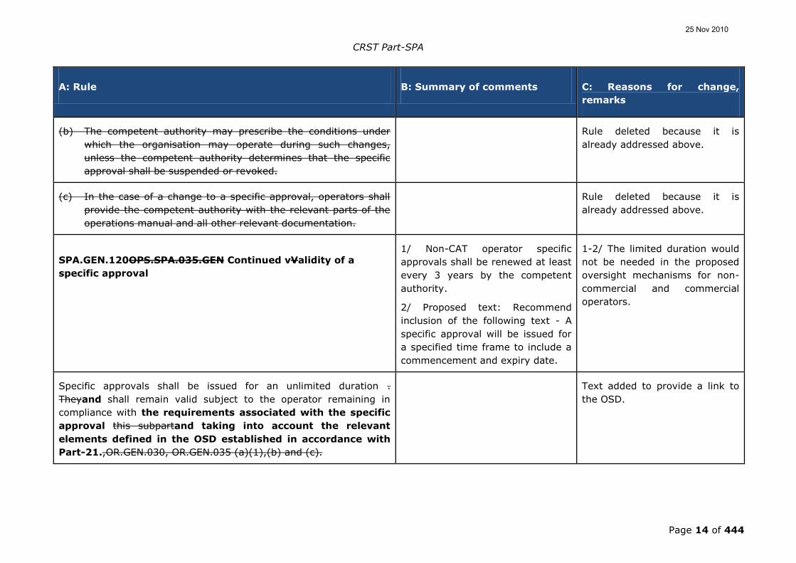
(vi) the duties of all personnel involved, especially with
relevance to ground handling and aircraft handling;
(vii) inspection for damage, leakage or contamination;
and
(viii) dangerous goods accident and incident reporting. Amended to align with EU-OPS
1.1225 and Part 7; 4.4 of the
Technical Instructions.
(c) An application for an approval to carry dangerous
goods shall include information on the classes of dangerous
goods intended to be carried.
6 comments received (MSx3 and
INDx3): Approvals are granted to
an operator to transport dangerous
goods in accordance with the
Technical Instructions. There is no
requirement within the Technical
Instructions, EU-OPS or JAR-OPS
for the operator to specify which
dangerous goods will be carried.
Therefore, this paragraph should
be deleted.
Paragraph deleted as
unnecessary and there being no
current requirement for the
information.
OPS.SPA.040DG.105 Dangerous goods information and
documentation
The operator shall, in accordance with the Technical Instructions:
25 Nov 2010

CRST Part-SPA
Page 34 of 444
A: Rule B: Summary of comments C: Reasons for change,
remarks
(a) provide personnel with the necessary information enabling
them to carry out their responsibilities;
Text moved to the relevant GEN
provision of the relevant
technical Parts since it applies to
all operators, not just those
approved to carry dangerous
goods.
(b) provide passengers with the necessary information on the
transport of dangerous goods;
This requirement is moved to
the relevant XXX.GEN provisions
of the technical Parts since it
applies to all operators, not just
those approved to transport
dangerous goods.
(ca) provide written information to the pilot-in-
command/commander:
(1) about dangerous goods to be carried on the aircraft;
(2) for use in responding to in-flight emergencies;
(db) use an acceptance checklist;
(ec) ensure that dangerous goods are accompanied by the required
dangerous goods transport document(s), as completed by the
person offering dangerous goods for air transport,
The text needs to take account of
electronic documentation
Text amended to take account
of electronic information. The
text takes into account that the
25 Nov 2010

CRST Part-SPA
Page 35 of 444
A: Rule B: Summary of comments C: Reasons for change,
remarks
except when the information applicable to the dangerous
goods is provided in electronic form;
operator needs to ensure that a
person offering DG has
completed the transport. This
addition was part of the
definition of “dangerous goods
transport document” and is
transferred into this provision to
improve clarity.
(fd) ensure that where a dangerous goods transport document
is provided in written form, a copy of the information to the
pilot-in-command and the dangerous goods transport document
is retained on the ground where it will be possible to obtain
access to it within a reasonable periodfor the duration of
the flight until the goods have reached their final
destination;
It was suggested that the text
concerning the NOTOC be
combined with
OPS.SPA.040.DG(g).
Text combined with
SPA.DG.105(g) and also
amended to align with the
requirements of the Technical
Instructions
(ge) ensure that a copy of the information to the pilot-in-
command/commander is retained on the ground and that
this copy, or the information contained in it, is readily
accessible to the aerodromes of last departure and next
scheduled arrival, until after the flight to which the
information refersavailable at the intended destination
aerodrome;
The text needs to provide for the
information to be available, not
necessarily the document itself, to
allow for the ability for the
information to be held
electronically.
Text amended to provide for a
copy of the document to be held
on the ground. Text also
amended to align with the
requirements of the Technical
Instructions to require the
document or the information on
it to be readily accessible at
both the aerodromes of
25 Nov 2010

CRST Part-SPA
Page 36 of 444
A: Rule B: Summary of comments C: Reasons for change,
remarks
departure and arrival.
(hf) retain the acceptance checklist, transport document and
information to the pilot in commandpilot-in-
command/commander for at least 3 three months after
completion of the flight; and
(ig) retain the training records of all personnel for at least 3 three
years.
Subpart D - Section VI - Helicopter operations without an
assured safe forced landing capability
OPS SPA 001 SFL should be
allowed only for operators holding
a commercial certificate.
Firstly because we do not require
private pilot to ensure a safe forced
landing when above a non-
congested hostile environment.
Moreover, it is based on specific
procedures, specific training, on
the analysis of usage monitoring
system and enhanced
Accepted.
The requirement for the safe-
forced-landing provisions is
derived from Annex 6 Part III,
Section II and has no relevance
to either AW or GA.
The Performance Subparts of
JAR-OPS 3 including the
provision of JAR-OPS 3.517 and
its associated Appendices and
Guidance are placed in
25 Nov 2010
CRST Part-SPA
Page 37 of 444
A: Rule B: Summary of comments C: Reasons for change,
remarks
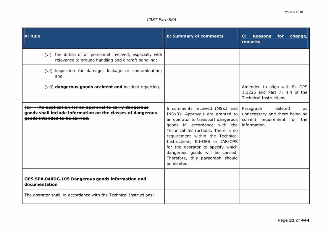
maintenance. It would be nonsense
to require it for private pilot and
will make the whole system fails.
We suggest transferring it into
CAT. It has to be consistent with
ETOPS.
CAT.POL.H and SPA.SFL was
removed.
No further comments with
regard to SFL for AW have been
entered in this text; SFL will
now only be available to CAT as
it is not required in AW or GA.
The IND and MS comments and a
large number of individuals (most
of them duplicated many time
over) were indicating the absence
of reciprocals in SFL.
Noted.
The issue is already included in
the rulemaking inventory as a
future rulemaking task.
A number of comments were
presented which requested an
increase in numbers for old
3.005(e) Appendix to seven.
Noted.
The target Appendix was
provided after careful
consideration of the risks
involved; the number has not
changed from the original in
JARs and has been extant for
almost a decade without
comment.
Any increase in the numbers
should only result from a
proposal to EASA and, if deemed
25 Nov 2010

CRST Part-SPA
Page 38 of 444
A: Rule B: Summary of comments C: Reasons for change,
remarks
worthy, followed by an NPA.
OPS.SPA.001.SFL Operations without an assured safe
forced landing capability
(a) A helicopter shall only be operated without an assured safe
forced landing capability if the operator has been approved by
the competent authority, specifying the type of helicopter and
operation.
1 manufacturer suggests a wording
change:
Wording modification proposal:
(a) For operations in accordance
with OPS.CAT.355.H, a helicopter
shall only be operated without an
assured safe forced landing
capability if the operator has been
approved by the competent
authority, specifying the type of
helicopter and operation.
Reason: consistency with
OPS.CAT.355.H (e) and new
proposed (f) where it is mentioned
that operations without an assured
SFL capability have to be
conducted under the conditions
contained in Subpart D Section VI.
Noted.
The exposure concept is
reinstated only in CAT as
provided in JAR-OPS 3.
25 Nov 2010

CRST Part-SPA
Page 39 of 444
A: Rule B: Summary of comments C: Reasons for change,
remarks
(b) To obtain such approval the operator shall:
(1) provide appropriate power unit reliability statistics for the
helicopter type and engine type;
Modify text:
(b)(1): the manufacturer provides
[...].
Noted.
Operational requirements are
aimed at operators and not
manufacturers; the application
for use of exposure can only
come from the operator; the
manufacturers have been
prepared to supply
documentation to the operator
so that it can be included in a
package from the applicant.
A more formal system of
reliability assessment may be
required.
Neither JAR-OPS 3.005(i)
[operations to a Public Interest
Site] nor JAR-OPS 3.005(e)
[operations over hostile terrain]
require operators to comply with
the full requirements of Appendix 1
to 3.517(a): JAR-OPS 3 required
compliance with only sub para
(a)(2)(i) & (ii).
Accepted.
The text of Appendices 3.005(e)
and 3.005(i) have been
transposed to CAT.POL.H.225
and CAT.POL.H.420 respectively.
25 Nov 2010

CRST Part-SPA
Page 40 of 444
A: Rule B: Summary of comments C: Reasons for change,
remarks
The EASA rule requires full
compliance with OPS.SPA.001.SFL
See para (b)(1).
Justification:
This rule impacts disproportionately
on smaller operators.
Proposed Text (if applicable):
OPS.SPA.001.SFL(b)(1) “except for
operations to a public interest site
or operations in Performance Class
3 when operating outside
congested hostile environment,
provide appropriate power unit....
OPS.SPA.001.SFL(b)(2) “) “except
for operations for a HEMS
operating site, a public interest site
or operations in Performance Class
3 when operating outside a
congested hostile environment,
assess the risk involved for.”
(2) except for a HEMS operating site, assess the risk involved
for:
(i) the type of helicopter to be used; and To obtain such an approval the
operator shall:
Accepted.
The text of JAR-OPS 3 has been
25 Nov 2010

CRST Part-SPA
Page 41 of 444
A: Rule B: Summary of comments C: Reasons for change,
remarks
(b) provide appropriate power unit
reliability statistics for the
helicopter type and engine type.
This should be for the combination
of helicopter and engine installed.
Due to commercial sensitivity,
manufacturers are not prepared to
issue primary reliability data to
operators. It is proposed that the
procedure used for JAR-OPS
3.517(a) compliance is adopted.
NPA OPS 38 to JAR-OPS 3 states
that the manufacturer must
provide the State of Design, or
State of First Certification in the
case on non EU manufacturers,
with the engine reliability data.
When this data is verified by the
competent authority, the
manufacturer issues a Service
Letter to all operators stating that
the helicopter meets the reliability
requirements. The operators then
utilise this letter when seeking this
approval.
reinstated.
25 Nov 2010

CRST Part-SPA
Page 42 of 444
A: Rule B: Summary of comments C: Reasons for change,
remarks
(ii) the type of operations conducted.
(3) establish operating procedures specifying:
(i) the take-off and landing techniques to be applied at
the aerodrome/operating site; and
The commentator states that there
is a problem with the application of
PIS in Germany. This problem is
political and not one that has been
introduced by the regulation.
Once the State accepts the
applicability of PISs, the problem
will have been resolved.
Noted.
This requirement was already
contained in Appendix 1 to JAR-
OPS 3.005(i) sub-paragraph (e).
The intent was to treat the PIS
as any other surveyed site, the
only exception being that the
PIS does not meet the
dimension or the obstacle
environment to allow for CAT A
procedures, hence the
requirement to establish which
causes the non-compliance
(obstacles or dimension) and
address that appropriately in the
Part C and by applying the site
specific procedure, either to
mitigate the risk due to the site
dimension not meeting CAT A
requirements or the obstacle
accountability.
25 Nov 2010

CRST Part-SPA
Page 43 of 444
A: Rule B: Summary of comments C: Reasons for change,
remarks
(ii) site specific procedures in the case of public interest
sites.
(4) implement a Usage Monitoring System; and A UMS only makes sense if the
helicopter is "on condition"
maintenance. As long there are
"hard times" as TBO it makes no
sense. OEM´s also do not issue any
limits for CS-27 helicopters.
Not accepted.
The requirement for UMS is
provided to ensure that the
engines are used only in
accordance with the limits
provided by the manufacturer.
(5) implement a set of conditions to obtain and maintain the
approval for a particular helicopter type; and
(6) establish and maintain a training programme for the crew
involved in these operations.
OPS.SPA.005.SFL Applicability
Operations without an assured safe forced landing capability shall
only be conducted in the following situations:
(a) at a HEMS operating site, when operating under an approval in
accordance with OPS.SPA.001.HEMS;
(b) operations to/from helidecks with helicopters which have a
maximum passenger seating configuration (MPSC) of more
Wording implies that this
alleviation is only open to
helicopters with an MPSC of more
Accepted
The restoration of the original
25 Nov 2010

CRST Part-SPA
Page 44 of 444
A: Rule B: Summary of comments C: Reasons for change,
remarks
than 19; than 19. rules of JAR-OPS 3 will resolve
the issue.
(c) for Performance Class 2 take-off or landing outside a congested
hostile environment:
(1) during the take-off phase, before reaching 200 ft above
the take-off surface; and
1 MS comments that subparagraph
(d)(1) requires amending as
detailed below.
Justification:
JAR-OPS 3.540 b) 1 includes the
additional proviso “before reaching
Vy”.
Proposed text: (d) for Performance
Class 3 operations, when operating
outside a congested hostile
environment: (1) during the take-
off phase, before reaching Vy or
200 ft above the take-off surface.
Accepted.
This will rectify itself when the
text of JARs in reinstated.
(2) during the landing phase, below 200 ft above the landing
surface.
(d) for Performance Class 3 operations, when operating outside a
congested hostile environment:
This alleviation has been
incorporated into Part OPS.SPA.
Most of the clauses have been
bound up into the requirement but
Accepted.
The original Appendix has been
included in CAT.POL.H.420.
25 Nov 2010

CRST Part-SPA
Page 45 of 444
A: Rule B: Summary of comments C: Reasons for change,
remarks
the original guidance on when it
might be applicable is missing.
It might be clearer if there was
guidance attached to
OPS.SPA.005.SFL paragraph
(d)(3). The JAR guidance was as
follows:
"IEM to Appendix 1 to JAR-OPS
3.005(e)
Helicopter operations over a hostile
environment located outside a
congested area
See Appendix 1 to JAR-OPS
3.005(e)
1 The subject Appendix has been
produced to allow a number of
existing operations to continue. It
is expected that the alleviation will
be used only in the following
circumstances:
1.1 Mountain Operations; where
present generation multi-engined
aircraft cannot meet the
requirement of Performance Class
25 Nov 2010

CRST Part-SPA
Page 46 of 444
A: Rule B: Summary of comments C: Reasons for change,
remarks
1 or 2 at altitude.
1.2 Operations in Remote Areas;
where existing operations are being
conducted safely; and where
alternative surface transportation
will not provide the same level of
safety as single-engined
helicopters;
2 The State issuing the AOC and
the State in which operations will
be conducted should give prior
approval.
3 If both approvals have been
given by a single State, it should
not withhold, without justification,
approval for aircraft of another
State.
4 Such approvals should only be
given after both States have
considered the technical and
economic justification for the
operation."
(1) during the take-off phase, before reaching 200 ft above
the take-off surface;
25 Nov 2010

CRST Part-SPA
Page 47 of 444
A: Rule B: Summary of comments C: Reasons for change,
remarks
(2) during the landing phase, below 200 ft above the landing
surface; and
(3) en-route in a specified, remote or mountain, area with
turbine powered helicopters with a MPSC of 6 or less.
Many comments proposed that the
limit be raised from six to seven.
Noted.
This goes beyond the
requirements of JAR-OPS
3.005(e); this should be the
subject of a proposal for NPA so
that it can be exposed to the
population of interested parties.
Proposal to introduce the new
(d)(4) condition:
(d)(4) en-route in a specified,
other than remote or mountain,
area with helicopters other than
complex motor-powered, provided
the flight time over hostile areas
does not exceed 5 -minutes periods
and 50 % of the overall flight time.
Rationale:
- Reason for this proposal is that
the current JAR-OPS 3 alleviation,
which is only valid for remote or
mountains areas, is too restrictive
for single-engine helicopters, and
25 Nov 2010

CRST Part-SPA
Page 48 of 444
A: Rule B: Summary of comments C: Reasons for change,
remarks
would result, if maintained, in
excluding single-engine helicopters
from a lot of CAT operations in
non-mountain areas, as soon as
there is for example a small forest
to cross. Maintaining unchanged
the JAR-OPS 3 text would very
likely condemn CAT with single-
engine helicopters in countries
filled with forests like Sweden orf
Finland.
- The proposal consists
in transferring in Part OPS the
French '5 minutes-50 %' condition
which has been part of the French
CAT Operational Regulation 'OPS 3'
since April 2004, and used up to
now by operators without any
safety problem.
- It is also based on a Eurocopter
analysis on the Ecureuil twin/single
helicopters family which has shown
that single-engine helicopters do
not cause more accidents than
twin-engine helicopters.
25 Nov 2010

CRST Part-SPA
Page 49 of 444
A: Rule B: Summary of comments C: Reasons for change,
remarks
(e) at a public interest site, with multi-turbine powered helicopters
with a MPSC of 6 or less:
Please remove "with multi-turbine
helicopters"!
Justification: There is no reason for
such a restriction. Think of the
catastrophic gear box failure of the
recent brand new Bond Helicopters
Super Puma, where the rotor
separated. Leave the decision
on the helicopter to be used to the
operators.
Not Accepted
The clause was only ever
applicable to twins.
Proposed modification:
at a public interest site with multi-
turbine powered helicopters with
an MPSC of 6 or less other than
'complex motor-powered'.
Consistency with the 'complex
motor-powered helicopter'
definition.
Not accepted.
This addition would deny access
to PIS for the BK117 and its
derivatives and the AW139;
there is no justification for this
as they were part of the original
scope of the rule. The problem
with PISs is not the aircraft
(they are capable of operating in
PC1) but the site itself.
(1) located in a congested hostile environment; Comment: OPS.SPA.005.SFL (e)
The OPS.SPA.005.SFL, para (e)
(see also the AMC
OPS.SPA.005.SFL (e)), does not
take into account the operations in
Noted.
The reason for the change was
the introduction of ground level
exposure into JAR-OPS 3 at AL5.
25 Nov 2010

CRST Part-SPA
Page 50 of 444
A: Rule B: Summary of comments C: Reasons for change,
remarks
a "non congested hostile
environment" at a public interest
site, with multi-turbine powered
helicopters with an MPSC of 6 or
less.
Justification: See Appendix 1 to
JAR-OPS 3.005 (i). Helicopter
operations at a public interest site,
para (2) (i) for operations in a "non
congested hostile environment"
(omission).
When the text is restored, this
clause will be left out of the rule
because it has become
redundant.
(2) established as public interest site before 1 July 2002; and (2) established as public interest
site before 1 July 2002 at the date
of entry into force of this
Regulation.
Reason: limiting the benefit of
operating without an SFL capability
to public interest sites (hospitals,
lighthouses) established as such
before 1 July 2002 is too
restrictive.
Not accepted
This date was justified with the
introduction of the provision for
public interest sites which was
introduced into JAR-OPS 3. The
reasons for it are contained in
the Guidance Material for PIS.
The rule introduces a subtle change
to the equivalent JAR- OPS 3 code
concerning Public Interest sites. At
OPS.SPA.005.SFL para (e)(2) the
Accepted.
JAR-OPS 3.005(i) has now been
reintroduced into
25 Nov 2010

CRST Part-SPA
Page 51 of 444
A: Rule B: Summary of comments C: Reasons for change,
remarks
text uses the term “”Public Interest
Site”, which changes the intent of
the JAR that, for the same purpose,
used the term “Heliport”.
A hospital landing site may have
been established for many years as
a heliport, but may not necessarily
have been established as a Public
Interest site. Such a heliport might
need to become a Public Interest
site with the introduction of new
aircraft with a helipad profile that
can no longer achieve a Class 1
profile, for example. The rule now
prevents categorisation of existing
Heliports as Public Interest sites.
Justification:
Overly-restrictive rule.
Proposed Text (if applicable):
OPS.SPA.005.SFL(2)
“Established as public interest site
a heliport before 1 July 2002”
CAT.POL.H.225.
(3) where the dimensions or obstacle environment do not
permit Performance Class 1 operations.
25 Nov 2010

CRST Part-SPA
Page 52 of 444
A: Rule B: Summary of comments C: Reasons for change,
remarks
OPS.SPA.035.SFL Helicopter Flight Manual Limitations
For helicopters certificated in Category A, a momentary flight
through the height velocity (HV) diagram is allowed during the take-
off and landing phases, when the helicopter is operated under the
approval in accordance with this section.
Whilst this derogation is welcome,
it only applies to those operators
who have applied for a received an
approval under Section VI of
Subpart D of Part OPS.
Unless this derogation is applicable
to all operations, all Part 29
helicopters (the position is unclear
for those helicopters which have
been approved under Appendix C
to Part 27) will have to apply the
limitation of the HV diagram. This
will restrict the operations of
complex helicopters to fly for Aerial
Work.
Accepted.
It is also noted from comments
that the HV diagram is also
mandated for Part 29 helicopters
certificated in CAT B.
This alleviation was originally
required for twins only as part of
JAR-OPS 3; it is clear that the
scope of EASA now requires that
this alleviation be applied for all
helicopters.
There is a need to reinstate
Appendix 1 to JAR-OPS
3.005(c). In addition, a similar
derogation is required for GA
and AW.
Alternatively, the HV diagram
can be taken out of the
limitations section of Part 29
helicopters.
The derogation to allow helicopters
certificated in Category A to
Accepted
25 Nov 2010

CRST Part-SPA
Page 53 of 444
A: Rule B: Summary of comments C: Reasons for change,
remarks
conduct momentary flight through
the height velocity (HV) curve is
welcomed, and the explanation for
this at NPA 2009-2A page 42 is
noted. However as it stands, it only
applies to those operators who
have applied for and received an
approval under applicability of
OPS.SPA.005.SFL. This derogation
derives from the requirement in
Appendix 1 to JAR-OPS 3.005(c).
The intention to initiate a
rulemaking task on CS-29 is also
noted but this will not assist
current operations beyond
OPS.SPA.001.SFL such as many
commercial (aerial work) activities.
It is not clear how other operations
under commercial (aerial work),
requiring similar clearance, will be
able to do so in the future.
Unless this derogation is made
applicable to all operations, all Part
29 helicopters (the position is
unclear for those helicopters which
have been approved under
Appendix C to Part 27) will have to
Further explanation.
25 Nov 2010

CRST Part-SPA
Page 54 of 444
A: Rule B: Summary of comments C: Reasons for change,
remarks
apply the limitation of the HV
diagram in accordance with Annex
IV 4.a of the Basic Regulation. This
will severely restrict the operations
of complex helicopters flying for
commercial (aerial work).
Subpart D H- Section VII – Helicopter operations with night
vision imaging systems
OPS.SPA.NVIS.00100.NVIS Night Vvision Iimaging Ssystem
(NVIS) operations
(a) A hHelicopters shall only be operated in night VFR operations
with the aid of night vision imaging systems (NVIS), if the
operator has been approved by the competent authority.
1. DGAC F asked if not possible
have reduced minima for NVIS
flight as similar to reduction in
minima found in HEMS.
2. LBA asked why the NPA is
considering only helicopters and
not all aircraft as JAA TGL 34
reports
1. This was rejected since NVIS
was always considered as an aid
to night VFR and not a means to
increase operations due to
reduction of minima.
2. The possibility to open up
NVIS for all types of aircraft was
discussed and was
recommended in the subgroup
aerial work of the working group
OPS.001. Leaflet TGL 34 (JAA
Administrative & Guidance
Material), was developed for
helicopter CAT use only and
25 Nov 2010

CRST Part-SPA
Page 55 of 444
A: Rule B: Summary of comments C: Reasons for change,
remarks
therefore this OPS NVIS is
limited to CAT operations only.
The issue of a dedicated NVIS
for other than CAT and other
then helicopters should be
subject to a future rulemaking
task.
(b) To obtain such approval by the competent authority, the
operator shall:
(1) operate in commercial air transport (CAT) and hold
a CAT air operator certificate (AOC) in accordance
with Part-ORestablish and maintain in addition to the
requirements contained in Part OR.OPS a specific training
and checking programme for the crew involved in these
operations; and
(2) demonstrate to the competent authority:establish
operating procedures specifying:
(i) compliance with the applicable requirements
contained in this Subpart;, and(i) the equipment to
be carried, including its operating limitations and
appropriate entries in the MEL;
Covered by SPA.NVIS.140.
(ii) the successful integration of all elements of the
NVIS.(ii) crew composition and experience
Covered by SPA.NVIS.130.
25 Nov 2010

CRST Part-SPA
Page 56 of 444
A: Rule B: Summary of comments C: Reasons for change,
remarks
requirements;
(iii) procedures for crew members wearing night vision
goggles;
Covered by SPA.NVIS.140.
(iv) procedures for the transition to and from an NVIS
flight;
Covered by SPA.NVIS.140.
(v) use of the radio altimeter on an NVIS flight; Covered by SPA.NVIS.140.
(vi) in-flight procedures for assessing visibility to ensure
that operations are not conducted below the minima
for non assisted night VFR flight.
Covered by SPA.NVIS.140.
OPS.SPA.NVIS.010110.NVIS Equipment requirements for
NVIS operations
In addition to the equipment required by OPS.GEN and OPS.CAT or
OPS.COM, helicopter involved in NVIS operations shall be equipped
with a radio altimeter and a low height warning system giving visual
and audio warnings selectable by the pilot and discernable during
NVIS operation.
1 IND proposed a change in
wording: In addition to the
equipment required by OPS.GEN
and, when applicable, OPS.CAT or
OPS.COM, …". This to avoid that
equipment required by OPS CAT or
OPS COM becomes mandatory as a
basis for NVIS operations
The comment was valid,
however it had been superseded
by adopting the original text of
JAR TGL 34.
The tailoring of JAA TGL 34 to
other then CAT (GEN and areal
work) is recommended to be
part of a new rulemaking task.
25 Nov 2010

CRST Part-SPA
Page 57 of 444
A: Rule B: Summary of comments C: Reasons for change,
remarks
(a) Before conducting NVIS operations each helicopter and
all associated NVIS equipment shall have been issued
with the relevant airworthiness approval in accordance
with Regulation (EC) No 1702/2003.
The Agency has on its inventory
a task to evaluate all
(additional) airworthiness
requirements related to
operations requiring a specific
approval, and address them in a
consistent manner. Therefore in
future review as part of that
task the text may be placed
elsewhere. In the meantime the
text is retained in Part-SPA, as
otherwise it is feared that the
requirement may not be
transposed before the
Implementing Rules enter into
effect, and thus the requirement
not being applied.
(b) Radio altimeter. The helicopter shall be equipped with a
radio altimeter and a low height warning system giving
visual and audio warnings selectable by the pilot and
discernable during head-up NVIS operation.
25 Nov 2010

CRST Part-SPA
Page 58 of 444
A: Rule B: Summary of comments C: Reasons for change,
remarks
(1) The radio altimeter shall:
(i) be of an analogue type display presentation
that requires minimal interpretation for both an
instantaneous impression of absolute height
and rate of change of height;
(ii) be positioned to be instantly visible and
discernable from each cockpit crew;
(iii) have an integral visual low height warning that
operates at a height selectable by the pilot; and
(iv) have an integral fail/no track indicator with
repeater light to give unambiguous warning of
radio altimeter fail or no track conditions.
(2) The visual warning system shall:
(i) provide clear visual warning at each cockpit
crew station of height below the pilot-selectable
warning height; and
(ii) have an instrument panel coaming repeater
light at each cockpit crew station to ensure
adequate attention-getting-capability for head
up operations.
(3) The audio warning system shall:
(i) be unambiguous and readily cancellable;
(ii) not extinguish any visual low height warnings
25 Nov 2010

CRST Part-SPA
Page 59 of 444
A: Rule B: Summary of comments C: Reasons for change,
remarks
when cancelled; and
(iii) operate at the same pilot selectable height as
the visual warning.
(d) Aircraft NVIS compatible lighting. To mitigate the
reduced peripheral vision cues and the need to enhance
situational awareness, the following shall be provided:
(1) NVIS-compatible instrument panel flood-lighting, if
installed, that can illuminate all essential flight
instruments;
(2) NVIS-compatible hand-held utility lights;
(3) portable NVIS compatible flashlight; and
(4) a means for removing or extinguishing internal
NVIS non-compatible lights.
(e) Additional NVIS equipment. The following additional
NVIS equipment shall be provided:
(1) a back-up or secondary power source for the night
vision goggles (NVGs);
(2) an NVIS adjustment kit or eye lane;
(3) a helmet with the appropriate NVG attachment.
(f) All required NVGs on an NVIS flight shall be of the same
type, generation and model.
25 Nov 2010

CRST Part-SPA
Page 60 of 444
A: Rule B: Summary of comments C: Reasons for change,
remarks
(g) Continuing airworthiness
(1) Procedures for continuing airworthiness shall
contain the information necessary for carrying out
ongoing maintenance and inspections on NVIS
equipment installed in the helicopter, and shall
cover, as a minimum:
(i) helicopter windscreens and transparencies;
(ii) NVIS lighting;
(iii) NVGs; and
(iv) any additional equipment that supports NVIS
operations.
(2) Any subsequent modification or maintenance to the
aircraft shall be in compliance with the NVIS
airworthiness approval.
OPS.SPA.NVIS.1020.NVIS NVIS operating minima
(a) Operations shall not be conducted below the visual flight
rules (VFR) weather minima for the type of night operations
being conducted.
1. proposed to add an “NVIS visual
range” of 1 500 m as mandatory in
addition to the night VFR minima
2. proposed to have a reduced
minima for NVIS operations based
on their experience of flying NVIS
1. The comment was not
accepted. Even if a safe
operation could be attained with
a “NVIS visual range” of
1 500 m using NVIS, The
operator should be able to
continue the flight in accordance
25 Nov 2010

CRST Part-SPA
Page 61 of 444
A: Rule B: Summary of comments C: Reasons for change,
remarks
with the applicable VFR minima
in case anything goes wrong
with the NVIS.
2. Comment not accepted.
Alleviations regarding operation
minima with NVIS are not
acceptable.
The minima given are absolute;
the operator should define
higher values for those pilots
with lesser experience.
(b) The operator shall establish the minimum transition
height from where a change to/from aided flight may be
continued.
OPS.SPA.NVIS..0130.NVIS Crew requirements for NVIS
operations
(a) Selection. The operator shall establish criteria for the
selection of crew members for the NVIS task.
(b) Experience. The minimum experience for the commander
shall not be less than 20 hours‟ VFR at night as pilot-in-
command/commander of a helicopter before
25 Nov 2010

CRST Part-SPA
Page 62 of 444
A: Rule B: Summary of comments C: Reasons for change,
remarks
commencing training.
(c) Operational training. All pilots shall have completed the
operational training in accordance with the NVIS
procedures contained in the operations manual.
(d) Recency. All pilots and NVIS technical crew members
conducting NVIS operations shall have completed three
NVIS flights in the last 90 days. Recency may be re-
established on a training flight in the helicopter or an
approved full flight simulator (FFS), which shall include
the elements of (f)(1)(ii) below.
(e) Crew composition. The minimum crew shall be the greater
of that specified:
(1) in the aircraft flight manual (AFM);
(2) for the underlying activity; or
(3) in the operational approval for the NVIS
operationsconsist of at least one pilot and one NVIS
technical crew member.
Several comments proposed that
for flights limiting usage of NVG
only and between helicopters a
single pilot operation could be
granted. 1 MS asked to justify the
reason of always having an NVIS
technical crew member.
The comment was accepted in
principle and now the new text
states that the minimum crew is
the greater of that specified in
the certification requirements,
particular kind of operation and
specific operation manual. This
is also similar to text in US NVIS
CONOPS RTCA DO 268.
(f) Crew training and cChecking
(1) Training and checking shall be conducted in
accordance with a detailed syllabus approved by the
competent authority and included in the operations
25 Nov 2010

CRST Part-SPA
Page 63 of 444
A: Rule B: Summary of comments C: Reasons for change,
remarks
manual.
(2) Crew members.
(i) Crew training programmes shall: improve
knowledge of the NVIS working environment
and equipment; improve crew co-ordination;
and include measures to minimise the risks
associated with entry into low visibility
conditions and NVIS normal and emergency
procedures.
(ii) The measures referred to in (i) above, shall be
assessed during:
(A) night proficiency checks; and
(B) line checks.
SPA.NVIS.140 Information and documentation
The operator shall ensure that, as part of its risk analysis and
management process, risks associated with the NVIS
environment are minimised by specifying in the operations
manual: selection, composition and training of crews; levels
of equipment and dispatch criteria; and operating procedures
and minima, such that normal and likely abnormal operations
are described and adequately mitigated.
25 Nov 2010

CRST Part-SPA
Page 64 of 444
A: Rule B: Summary of comments C: Reasons for change,
remarks
Subpart D I- Section VIII – Helicopter hoist operations A number of comments were
concerned with the examination of
the engine reliability for singles –
this was then related to SAR. These
were not accepted for the following
response:
The comment is unspecific but
could be understood as a
proposal to remove the
performance requirements from
HEMS all together, rather than
maintaining the current
alleviation from HHO at a HEMS
operating site. SAR is still the
responsibility of the national
authority, however the Member
States shall undertake to ensure
that such services have due
regard as far as practicable to
the objectives of the Basic
Regulation and its IRs.
OPS.SPA.HHO.00100.HHO Helicopter hoist operations (HHO) A number of comments were
concerned with the absence of
appropriate regulations for AW.
Noted. The subject of HEC needs
to be considered as a separate
activity. HHO was always
considered as a CAT activity –
hence the requirement for
engine-failure accountability.
HEC Class D only is addressed in
this set of requirements and, in
view of that, it is a CAT activity.
HEC Classes A, B and C are
addressed under Part-SPO by
requiring the operator to
25 Nov 2010

CRST Part-SPA
Page 65 of 444
A: Rule B: Summary of comments C: Reasons for change,
remarks
establish appropriate SOP. This
Subpart could be extended in
the future to also encompass
HEC class A, B and C operations.
(a) A hHelicopters shall only be operated for the purpose of
commercial air transport hoist operations, if the operator
has been approved by the competent authority.
(b) To obtain such approval by the competent authority, the
operator shall:
(1) operate in commercial air transport (CAT) and hold
a CAT air operator certificate (AOC) in accordance
with Part-OR; and
(21) demonstrate to the competent authority
compliancecomply with the applicable requirements
contained in this SubpartOPS.GEN, OPS.CAT, OPS.COM
andPart-OR, except for the variations contained in this
Section.;
(2) establish and maintain in addition to the requirements
contained in Part OR.OPS a specific training and checking
programme for the crew involved in these operations; and
Covered by SPA.HHO.130
(3) establish operating procedures specifying: There were several comments
requesting the reintroduction of the
Partially accepted.
The requirement for a
25 Nov 2010
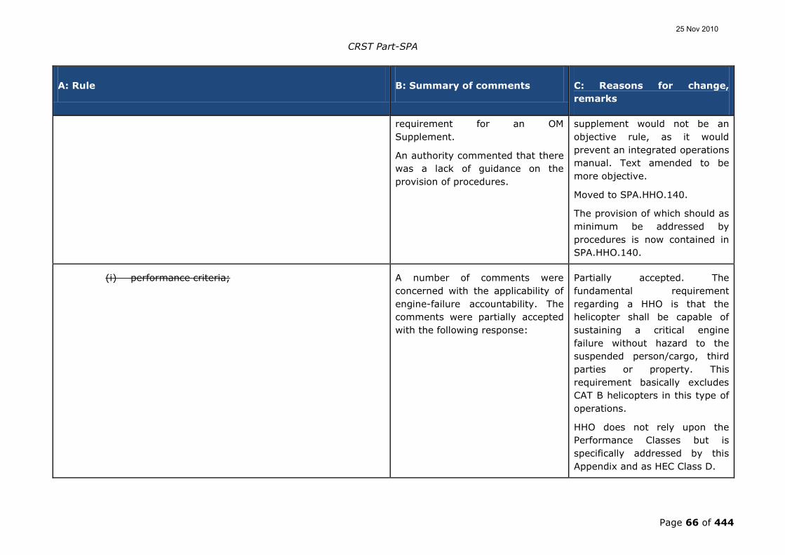
CRST Part-SPA
Page 66 of 444
A: Rule B: Summary of comments C: Reasons for change,
remarks
requirement for an OM
Supplement.
An authority commented that there
was a lack of guidance on the
provision of procedures.
supplement would not be an
objective rule, as it would
prevent an integrated operations
manual. Text amended to be
more objective.
Moved to SPA.HHO.140.
The provision of which should as
minimum be addressed by
procedures is now contained in
SPA.HHO.140.
(i) performance criteria; A number of comments were
concerned with the applicability of
engine-failure accountability. The
comments were partially accepted
with the following response:
Partially accepted. The
fundamental requirement
regarding a HHO is that the
helicopter shall be capable of
sustaining a critical engine
failure without hazard to the
suspended person/cargo, third
parties or property. This
requirement basically excludes
CAT B helicopters in this type of
operations.
HHO does not rely upon the
Performance Classes but is
specifically addressed by this
Appendix and as HEC Class D.
25 Nov 2010
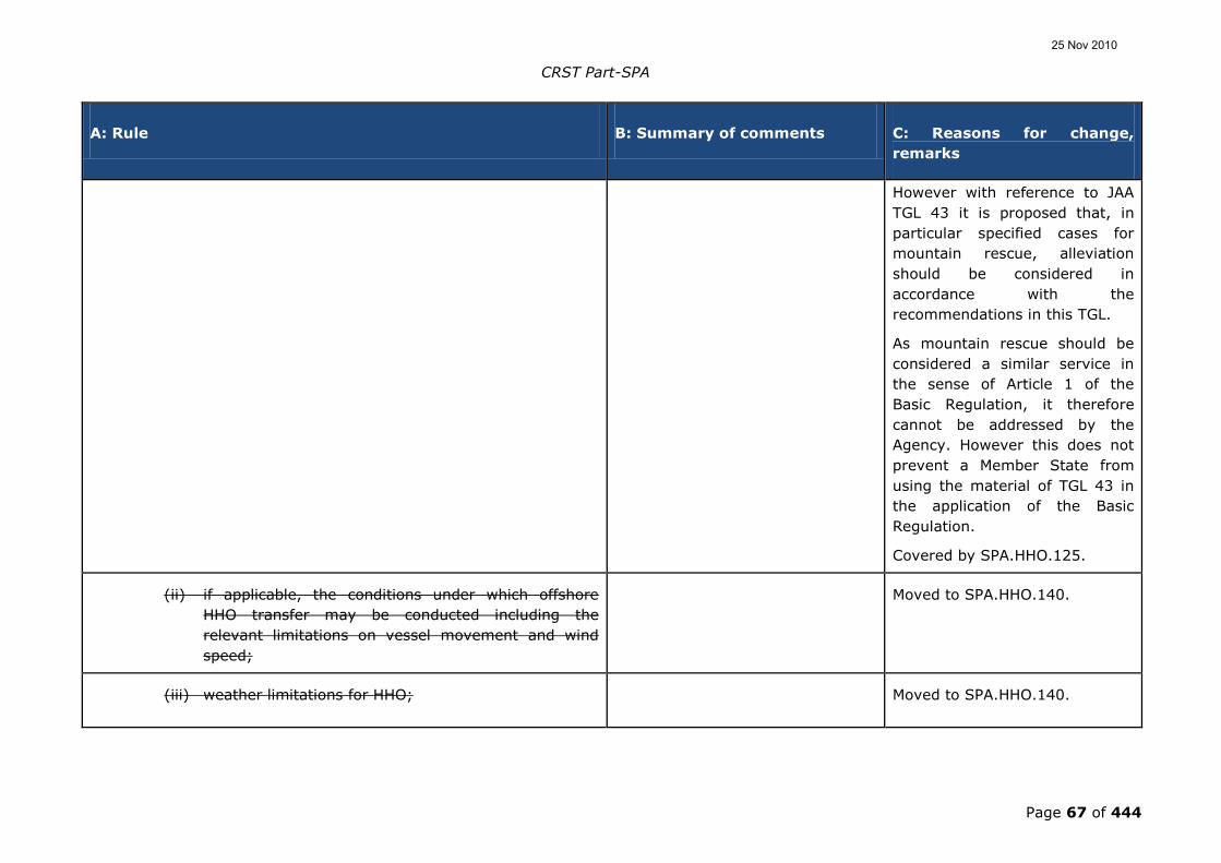
CRST Part-SPA
Page 67 of 444
A: Rule B: Summary of comments C: Reasons for change,
remarks
However with reference to JAA
TGL 43 it is proposed that, in
particular specified cases for
mountain rescue, alleviation
should be considered in
accordance with the
recommendations in this TGL.
As mountain rescue should be
considered a similar service in
the sense of Article 1 of the
Basic Regulation, it therefore
cannot be addressed by the
Agency. However this does not
prevent a Member State from
using the material of TGL 43 in
the application of the Basic
Regulation.
Covered by SPA.HHO.125.
(ii) if applicable, the conditions under which offshore
HHO transfer may be conducted including the
relevant limitations on vessel movement and wind
speed;
Moved to SPA.HHO.140.
(iii) weather limitations for HHO; Moved to SPA.HHO.140.
25 Nov 2010

CRST Part-SPA
Page 68 of 444
A: Rule B: Summary of comments C: Reasons for change,
remarks
(iv) criteria for determining the minimum size of the HHO
site, appropriate to the task;
A comment made reference to the
lack of guidance for the size of the
HHO site. This was not accepted
with the following response:
Not accepted. The rule itself
does not specify any limitation
neither regarding weather nor
minimum size of the HHO site.
However the operator is
required to establish procedures
specifying limiting weather
factors and criteria for
determining minimum size of
the HHO site. Even a HEMS
mission should be carried out in
accordance with procedures laid
down beforehand by the
operator, which also concern
weather and sites.
Moved to SPA.HHO.140.
(v) crew composition and experience requirements; and Covered by SPA.HHO.130.
(vi) the method by which crew members record hoist
cycles.
Moved to SPA.HHO.140.
OPS.SPA.HHO.010110.HHO Equipment requirements for HHO
(a) The installation of all helicopter hoist equipment, including any
radio equipment to comply with OPS.SPA.HHO.0115,.HHO and
A comment asked that the
instruction be more precise and
Noted. For HHO – i.e. HEC Class
D – the personnel carrying
25 Nov 2010

CRST Part-SPA
Page 69 of 444
A: Rule B: Summary of comments C: Reasons for change,
remarks
any subsequent modifications and, where applicable, its
operation shall have an airworthiness approval appropriate to
the intended function. Ancillary equipment must shall be
designed and tested to the appropriate standard as required by
the competent authority.
contested that only those parts
down to the hook had to have
approval.
device system (PCDS) is subject
to airworthiness approval.
(b) Maintenance instructions for HHO equipment and systems shall
be established by the operator, in liaison with the manufacturer
and included in the operator‟s helicopter maintenance
programme as required by Regulation (EC) No 2042/2003in
Part-M.
A comment made reference to the
lack of cooperation from
manufacturers with respect to this
provision.
Not accepted. “The maintenance
instructions for HHO equipment
and systems shall be established
by the operator, in liaison with
the manufacturer.” It is the
responsibility of the operator to
establish the instructions.
However, even if the
manufacturer has little or
nothing to bring to the
maintenance instructions a
consultation with the
manufacturer is reasonable.
OPS.SPA.HHO.0115.HHO HHO communication
Two-way radio communication shall be established with the
organisation for which the HHO is being provided and, where
possible, a means of communicationg with ground personnel at the
HHO operating site of that organisation for:
A comment stated that the intent
of this text was to require
communication with ground
personnel at the operating site (it
is unclear whose organisation).
Accepted. The NPA text does not
clearly enough specify that the
“ground personnel” should be at
the HHO site. Whether those
“ground personnel” are engaged
25 Nov 2010

CRST Part-SPA
Page 70 of 444
A: Rule B: Summary of comments C: Reasons for change,
remarks
Perhaps this should be stated in
the requirement:
"Two-way communication...with
ground personnel at the HHO Site
for:"
with the organisation for which
the HHO is being provided or
engaged with the operator is
insignificant.
(a) day and night offshore operations; and
(b) night onshore operations, except for HHO at a helicopter
emergency medical services (HEMS) operating site.
A comment stated that for HHO at
a HEMS operating site there would
be no ground personnel and the
text should reflect his.
Partially accepted. It is not
justifiable that the requirement
of a two-way communication
might stop a HEMS mission at
night. It is proposed to handle
this as engine failure
accountability in connection with
HHO/HEMS. “Except for HEMS at
the HEMS operating site....”
OPS.SPA.HHO.125.HHO Performance requirements for HHO
operations
Except for HHO operations at a HEMS Ooperating Ssite, HHO
operations performed as Commercial Air Transport (CAT) shall be
capable of sustaining a critical power unitengine failure with the
remaining engine(s) at the appropriate power setting, without
hazard to the suspended person(s)/cargo, third parties, or property.
A comment pointed out that this
requirement was not consistent
with the text of the AMC.
The inconsistency has been
removed by a clear reference
that this Subpart only applies to
CAT
25 Nov 2010

CRST Part-SPA
Page 71 of 444
A: Rule B: Summary of comments C: Reasons for change,
remarks
OPS.SPA.HHO.030130.HHO Crew requirements for HHO
operations
(a) Selection. The operator shall establish criteria for the
selection of flight crew members for the HHO task,
taking previous experience into account.
(b) Experience. The minimum experience level for the
commander conducting HHO flights shall not be less
than:
(1) Offshore:
(i) 1 000 hours as pilot-in-command/commander
of helicopters, or 1 000 hours as co-pilot in HHO
of which 200 hours is as pilot-in-command
under supervision; and
(ii) 50 hoist cycles conducted offshore, of which 20
cycles shall be at night if night operations are
being conducted, where hoist cycle means one
down and up cycle of the hoist hook.
(2) Onshore:
(i) 500 hours as pilot-in-command/commander of
helicopters, or 500 hours as co-pilot in HHO of
which 100 hours is as pilot-in-command under
supervision;
25 Nov 2010

CRST Part-SPA
Page 72 of 444
A: Rule B: Summary of comments C: Reasons for change,
remarks
(ii) 200 hours‟ operating experience in helicopters
gained in an operational environment similar to
the intended operation; and
(iii) 50 hoist cycles, of which 20 cycles shall be at
night if night operations are being conducted.
(c) Operational training and experience. Successful
completion of training in accordance with the HHO
procedures contained in the operations manual and
relevant experience in the role and environment under
which HHO are conducted.
(d) Recency. All pilots and HHO crew members conducting
HHO shall have completed in the last 90 days:
(1) when operating by day: any combination of three
day or night hoist cycles, each of which shall include
a transition to and from the hover; and
(2) when operating by night: three night hoist cycles,
each of which shall include a transition to and from
the hover.
(e) Crew composition. The minimum crew for day or night
operations shall be as stated in the operations manual.
The minimum crew will be dependent on the type of
helicopter, the weather conditions, the type of task, and,
in addition for offshore operations, the HHO site
environment, the sea state and the movement of the
25 Nov 2010

CRST Part-SPA
Page 73 of 444
A: Rule B: Summary of comments C: Reasons for change,
remarks
vessel. In no case shall the minimum crew be less than
one pilot and one HHO crew member.
The minimum crew shall consist of at least one pilot and one HHO
technical crew member.
(f) Training and checking
(1) Training and checking shall be conducted in
accordance with a detailed syllabus approved by the
competent authority and included in the operations
manual.
(2) Crew members
(i) Crew training programmes shall: improve
knowledge of the HHO working environment
and equipment; improve crew coordination; and
include measures to minimise the risks
associated with HHO normal and emergency
procedures and static discharge.
(ii) The measures referred to in (i) above, shall be
assessed during visual meteorological
condictions (VMC) day proficiency checks, or
VMC night proficiency checks when night HHO
are undertaken by the operator.
SPA.HHO.135 HHO Passenger briefing
25 Nov 2010

CRST Part-SPA
Page 74 of 444
A: Rule B: Summary of comments C: Reasons for change,
remarks
Prior to any HHO flight, or series of flights, HHO passengers
shall have been briefed and made aware of the dangers of
static electricity discharge and other HHO considerations.
SPA.HHO.140 Information and documentation
(a) The operator shall ensure that, as part of its risk analysis
and management process, risks associated with the HHO
environment are minimised by specifying in the
operations manual: selection, composition and training
of crews; levels of equipment and dispatch criteria; and
operating procedures and minima, such that normal and
likely abnormal operations are described and adequately
mitigated.
(b) Relevant extracts from the operations manual shall be
available to the organisation for which the HHO is being
provided.
Subpart D J - Section IX - Helicopter emergency medical
service operations
MS comments were made on
problems that are addressed in
43, and the fact that HEMS is
considered CAT and needs to be
returned to that section.
TGL 43 distinguishes between
HEMS and mountain rescue. HEMS
being subject to the Basic
25 Nov 2010

CRST Part-SPA
Page 75 of 444
A: Rule B: Summary of comments C: Reasons for change,
remarks
Regulation (BR) and its
Implementing Rules, whereas
mountain rescue is similar to
Search and Rescue and therefore is
outside the scope of the BR (Art. 1)
OPS.SPA.HEMS.001100.HEMS Helicopter emergency medical
service (HEMS)operations (HEMS)
It is noted that there has been a
large number of duplicate
comments from operators from the
alpine region.
Some comments related to SAR
operations, however SAR is outside
the Community scope (Art. 1 of
Regulation 1108/2009).
(a) Helicopters shall only be operated for the purpose of Helicopter
Emergency Medical Service (HEMS )oOperations, if the operator
has been approved by the competent authority.
(b) To obtain such approval by the competent authority, the
operator shall:
(1) operate in commercial air transport (CAT) and hold a
CAT commercial air transport operator certificate (AOC)
in accordance with Part-OR; and
One comment related to this article
understood this to mean that State
aircraft were excluded from
performing HEMS.
The Basic Regulation does not
25 Nov 2010
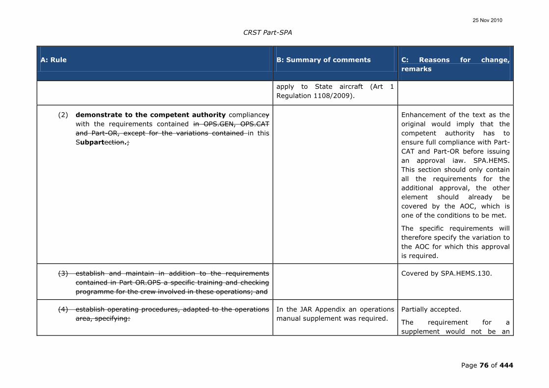
CRST Part-SPA
Page 76 of 444
A: Rule B: Summary of comments C: Reasons for change,
remarks
apply to State aircraft (Art 1
Regulation 1108/2009).
(2) demonstrate to the competent authority compliancey
with the requirements contained in OPS.GEN, OPS.CAT
and Part-OR, except for the variations contained in this
Subpartection.;
Enhancement of the text as the
original would imply that the
competent authority has to
ensure full compliance with Part-
CAT and Part-OR before issuing
an approval iaw. SPA.HEMS.
This section should only contain
all the requirements for the
additional approval, the other
element should already be
covered by the AOC, which is
one of the conditions to be met.
The specific requirements will
therefore specify the variation to
the AOC for which this approval
is required.
(3) establish and maintain in addition to the requirements
contained in Part OR.OPS a specific training and checking
programme for the crew involved in these operations; and
Covered by SPA.HEMS.130.
(4) establish operating procedures, adapted to the operations
area, specifying:
In the JAR Appendix an operations
manual supplement was required.
Partially accepted.
The requirement for a
supplement would not be an
25 Nov 2010

CRST Part-SPA
Page 77 of 444
A: Rule B: Summary of comments C: Reasons for change,
remarks
objective rule, as it would
prevent an integrated operations
manual. Text amended to be
more objective.
Moved to SPA.HEMS.140.
(i) HEMS operating minima; Covered by SPA.HEMS.120.
(ii) performance requirements; Covered by SPA.HEMS.125.
(iii) crew composition and experience requirements; Covered by SPA.HEMS.130.
(iv) recommended routes for regular flights to surveyed
sites with the minimum flight altitude;
Comments to this point have
demonstrated that operators do
not understand that this applies to
surveyed sites and therefore there
shall be recommended routes, due
to obstacle situation etc. In the
case of unsurveyed sites, point (v)
is applicable.
Restoration of the rule versus
AMC/GM solves this
misunderstanding. Moved to
AMC1-SPA.HEMS.140.
(v) guidance for the selection of the HEMS operating site
in case of a flight to an unsurveyed site;
Moved to AMC1-SPA.HEMS.140.
(vi) guidance on take-off and landing procedures at Moved to SPA.HEMS.125.
25 Nov 2010

CRST Part-SPA
Page 78 of 444
A: Rule B: Summary of comments C: Reasons for change,
remarks
unsurveyed HEMS operating sites;
(vii) the safety altitude for the area over flown; Moved to AMC1-SPA.HEMS.140.
(viii) procedures to be followed in case of inadvertent flight
into cloud;
Moved to AMC1-SPA.HEMS.140.
(ix) procedures for the use of portable equipment on
board; and
Moved toSPA.HEMS.140.
(x) briefing of medical staff prior to any HEMS flight, or
series of flights.
Covered by SPA.HEMS.130.
OPS.SPA.HEMS.0110.HEMS Equipment requirements for HEMS
operations
It is noted that there has been a
large number of duplicate
comments from operators from the
alpine region.
(a) The installation of all helicopter dedicated medical equipment
and any subsequent modifications and, where appropriate, its
operation shall be approved in accordance with Regulation (EC) No
1702/2003Part-21.
Several duplicate comments were
received regarding improvement of
the text as certification is only
required for the fixture and fittings
and not for the medical equipment
itself.
Not accepted.
Text is correct; only the
„installation‟ needs a Part-21
approval. The text has not been
changed.
25 Nov 2010

CRST Part-SPA
Page 79 of 444
A: Rule B: Summary of comments C: Reasons for change,
remarks
SPA.HEMS.115 - Communication
In addition to that required by CAT.IDE.H, (b)
Hhelicopters conducting HEMS flights shall have be provided
with communication equipment , in addition to that required for
commercial air transport operations,capable of conducting two-way
communication with the organisation for which the HEMS is being
conducted and, where possible, to communicate with ground
emergency service personnel.
One comment related to the
inclusion of guidelines for the non-
certified equipment for voice and
data transmission.
Not accepted.
Text is correct and the
equipment is already covered by
existing rules.
OPS.SPA.HEMS.0120.HEMS HEMS operating minima It is noted that there has been a
large number of duplicate
comments from operators from the
alpine region.
(a) HEMS flights operated in performance class 1 and 2 operations
shall comply with the weather minima in Table 1 for dispatch
and, Table 1 and the associated notes for the en-route phase of
the HEMS flight. In the event that during the en-route phase
the weather conditions fall below the cloud base or visibility
minima shown, helicopters certificated for flights only under
visual meteorological conditions ((VMC)) shall abandon the
flight or return to base. Helicopters equipped and certificated
for instrument meteorological conditions (IMC) operations
may abandon the flight, return to base or convert in all
respects to a flight conducted under IFR, provided the flight
One operator requested to lower
the operating minima at night if
NVIS were to be used.
Not accepted.
Alleviation regarding operating
minima with use of NVIS is not
accepted.
25 Nov 2010

CRST Part-SPA
Page 80 of 444
A: Rule B: Summary of comments C: Reasons for change,
remarks
crew are suitably qualified.
Table 1:OPS.SPA.020 - HEMS operating minima Some comments related to the fact
that one pilot and one HEMS
technical crew member should be
allowed to use the 2 pilot operating
minima.
Not accepted.
A HEMS technical crew member
is not a pilot and therefore the
operation cannot be credited as
such.
2 PILOTS 1 PILOT
DAY
Ceiling Visibility Ceiling Visibility
500 ft and
above
As defined by
the applicable
airspace VFR
minima
500 ft and
above
As defined by
the applicable
airspace VFR
minima
499 - 400 ft 1 000 m* 499 – 400 ft 2 000 m
399 - 300 ft 2 000 m 399 – 300 ft 3 000 m
NIGHT
Cloud Bbase Visibility Cloud Bbase Visibility
Most of the duplicate comments
requested to change the visibility in
note 1 from 800 m to 500 m, and
one commentator suggested
removing the clause in total.
Not accepted.
These duplicate comments only
indicated that in one or two of
the Member States this is
allowed. It is therefore
inappropriate to change the
current text.
25 Nov 2010

CRST Part-SPA
Page 81 of 444
A: Rule B: Summary of comments C: Reasons for change,
remarks
1 200 ft ** 2 500 m 1 200 ft** 3 000 m
* During the en-route phase vVisibility may be reduced to 800 m
for short periods when in sight of land if the helicopter is
manoeuvred at a speed that will give adequate opportunity to
observe any obstacles in time to avoid a collision.
** During the en-route phase, cCloud base may be reduced to 1
000 ft for short periods.
(b) The weather minima for the dispatch and en-route phase of a
HEMS flight operated in performance class 3 operations shall
be a cloud ceiling of 600 ft and a visibility of 1 500 m.
Visibility may be reduced to 800 m for short periods
when in sight of land if the helicopter is manoeuvred at a
speed that will give adequate opportunity to observe any
obstacle and avoid a collision.
Most of the duplicate comments
related to the omission of the note
* above to be applied to PC 3
operations as well.
Accepted.
Text included
OPS.SPA.HEMS.0125.HEMS Performance requirements for
HEMS operations
It is noted that there has been a
large number of duplicate
comments from operators from the
alpine region.
(a) Performance class 3 operations shall not be conducted over a
hostile environment.
Some opposing comments on this
issue were received. Most of the
commentators requested
Not accepted.
There is currently no reason to
25 Nov 2010

CRST Part-SPA
Page 82 of 444
A: Rule B: Summary of comments C: Reasons for change,
remarks
alleviation from this requirement
indicated that there is an urgent
need to transpose TGL 43 into the
EASA system. There were other
comments that requested that for
HEMS no performance class 3
should be allowed at all.
deviate from the requirements
already contained in JAR-OPS 3.
On the other hand transposition
of TGL 43 should be undertaken
with urgency so that some
misunderstanding of the
requirements can be properly
addressed.
(b) Take-off and landing Most of the comments indicate
widespread misunderstanding of
the rules, from either the operator
or the authorities. Proposals are
made to change the content to
address those misunderstandings.
Not accepted.
The fact that several authorities
have not implemented the public
interest site appendix, does not
justify a change in the rules.
Exposure during take-off and
landing is not equal to PC3;
helicopters being unable to meet
PC2 requirements at altitude do
not justify the use of PC3 in
HEMS operations below those
altitudes where PC2 would
otherwise be possible.
(1) Helicopters conducting operations to/from an aerodrome
at a hospital which that is located in a hostile
environment shall be operated in accordance with
performance class 1;, except when the operator holds
One NAA commented that a HEMS
operating base should be located
outside congested area, especially
if night operations are conducted.
Not accepted.
A congested area requires PC1,
so therefore caters for the N-1
situation. Therefore there is no
25 Nov 2010

CRST Part-SPA
Page 83 of 444
A: Rule B: Summary of comments C: Reasons for change,
remarks
an approval in accordance with CAT.POL.H.225as
provided for in OPS.SPA.005.SFL.
reduced risk with regard to
performance, even in the case of
night operations.
(2) Helicopters conducting operations to/from an HEMS
operating site located in a hostile environment shall be
operated in accordance with performance class 2, and
exempt from the approval required by
CAT.POL.H.305(a), provided compliance is shown
with CAT.POL.H.305, (b)(2)and(3).
Added text is the result of the
preferred option 2(c) of the
HSST/WP-07/03.4
(3) The HEMS operating site shall be big enough to provide
adequate clearance from all obstructions. For night
operations, the site shall be illuminated to enable the site
and any obstructions to be identified.
SPA.HEMS.130 - Crew requirements
Transposed from AMC to be
consistent with OR.OPS.FC and
OR.OPS.TC.
25 Nov 2010

CRST Part-SPA
Page 84 of 444
A: Rule B: Summary of comments C: Reasons for change,
remarks
1. The crew(a) 1.1 Selection. The operatiorns manual
should contain specific shall establish criteria for the selection
of flight crew members for the HEMS task, taking previous
experience into account.
(b) 1.2 Experience. The minimum experience level for the
commander conducting HEMS flights shall not be less
than:
(1)a. Eeither:
(i). 1 000 hours as pilot-in-command/commander of
aircraft of which 500 hours isare as pilot-in-
command/commander on helicopters; or
(ii). 1 000 hours as co-pilot in HEMS operations of which
500 hours is are as pilot-in-command under
supervision; and, 100 hours pilot-in-
command/commander of helicopters;.
(2)b. 500 hours operating experience in helicopters, gained
in an operational environment similar to the intended
operation; and
(3)c.fFor pilots engaged in night operations, 20 hours of Visual
Meteorological Conditions (VMC) at night as pilot-in-
command/commander.; and
(c)d. Operational training. Successful completion of operational
training in accordance with the HEMS procedures contained
in the operations manual 1.5.1.
Moved from AMC
OPS.SPA.001.HEMS(b)(4).
25 Nov 2010

CRST Part-SPA
Page 85 of 444
A: Rule B: Summary of comments C: Reasons for change,
remarks
(d)1.3 Recency. All pilots conducting HEMS operations shallould
have completed a minimum of 30 minutes‟ flight by sole
reference to instruments in a helicopter or in a flight
simulation synthetic training device (FSTD) within the last
six6 months.
(e)1.4 Crew composition.
(1)a. Day flight. The minimum crew by day shallould be one
pilot and one HEMS technical crew member.
(i) This may can be reduced to one pilot only whenin
exceptional circumstances:
(A) at a HEMS operating site the /commander
is required to fetch additional medical
supplies. In such case the HEMS technical
crew member may be left to give
assistance to ill or injured persons while
the commander undertakes this flight;
(B) after arriving at the HEMS operating site,
the installation of the stretcher precludes
the HEMS technical crew member from
occupying the front seat; or
(C) the medical passenger requires the
assistance of the HEMS technical crew
member in flight.
25 Nov 2010

CRST Part-SPA
Page 86 of 444
A: Rule B: Summary of comments C: Reasons for change,
remarks
(ii) In the cases described in (i), the operational
minima shall be as defined by the applicable
airspace requirements; the HEMS operating
minima contained in Table 1 of SPA. HEMS.120
shall not be used.
(iii) Only in the case described in (i)(A) may the
commander land at a HEMS operating site
without the technical crew member assisting
from the front seat.
25 Nov 2010

CRST Part-SPA
Page 87 of 444
A: Rule B: Summary of comments C: Reasons for change,
remarks
(2)b. Night flight. The minimum crew by night shallould be:
(i) two pilots; or
(ii) . However, one pilot and one HEMS technical crew
member may be employed in specific geographical
areas defined by the operator in the operations
manual taking into account the following:
(A)i. aAdequate ground reference;
(B)ii. fFlight following system for the duration of the
HEMS mission;
(C)iii.rReliability of weather reporting facilities;
(D)iv. HEMS minimum equipment list;
(E)v. cContinuity of a crew concept;
(F)vi. mMinimum crew qualification, initial and
recurrent training;
(G)vii. oOperating procedures, including crew
co-ordination;
(H)viii. wWeather minima; and
(I)ix. aAdditional considerations due to specific local
conditions.
(f)1.5 Crew training and checking
(1) Training and checking shall be conducted in
25 Nov 2010

CRST Part-SPA
Page 88 of 444
A: Rule B: Summary of comments C: Reasons for change,
remarks
accordance with a detailed syllabus approved by the
competent authority and included in the operations
manual.
(2) Crew members
(i) Crew training programmes shall: improve
knowledge of the HEMS working environment
and equipment; improve crew coordination; and
include measures to minimise the risks
associated with en-route transit in low visibility
conditions, selection of HEMS operating sites,
and approach and departure profiles.
(ii) The measures referred to in (i) above shall be
assessed during:
(A) VMC day proficiency checks, or VMC night
proficiency checks when night HEMS
operations are undertaken by the operator;
and
(B) line checks.1.5.1 Flight crew members
a. The specific HEMS training programme for the flight
crew members should include the following subjects:
i. Meteorological training concentrating on the
understanding and interpretation of available
weather information;
ii. Preparing the helicopter and specialist medical
equipment for subsequent HEMS departure;
25 Nov 2010

CRST Part-SPA
Page 89 of 444
A: Rule B: Summary of comments C: Reasons for change,
remarks
iii. Practice of HEMS departures;
iv. The assessment from the air of the suitability of
HEMS operating sites; and
v. The medical effects air transport may have on
the patient.
b. crew member checking
i. VMC day proficiency checks, or also at night if
night HEMS operations are undertaken by the
operator, including flying landing and take-off
profiles likely to be used at HEMS operating
sites.
ii. Line checks, with special emphasis on the
following:
gA. Local area meteorology;
hB. HEMS flight planning;
iC. HEMS departures;
jD. The selection from the air of HEMS operating sites;
E. Low level flight in poor weather; and
F. Familiarity with established HEMS operating sites in operators
local area register.
1.5.2 HEMS Technical crew member
The specific HEMS training programme for technical crew
members who perform assigned duties relating to
25 Nov 2010

CRST Part-SPA
Page 90 of 444
A: Rule B: Summary of comments C: Reasons for change,
remarks
assisting the pilot in his duties should include the following
items in addition to Part-OR:
a. Duties in the HEMS role;
b. Navigation (map reading, navigation aid principles
and use);
c. Operation of radio equipment;
d. Use of onboard medical equipment;
e. Preparing the helicopter and specialist medical
equipment for subsequent HEMS departure;
f. Instrument reading, warnings, use of normal and
emergency check lists in assistance of the pilot as
required;
g. Basic understanding of the helicopter type in terms of
location and design of normal and emergency
systems and equipment;
h. Crew coordination;
i. Practice of response to HEMS call out;
j. Conducting refuelling and rotors running refuelling;
k. HEMS operating site selection and use;
l. Techniques for handling patients, the medical
consequences of air transport and some knowledge of
hospital casualty reception;
25 Nov 2010
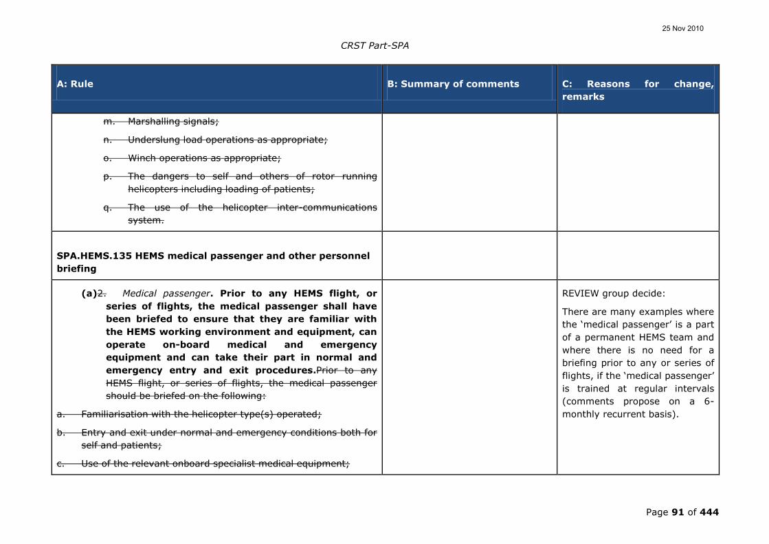
CRST Part-SPA
Page 91 of 444
A: Rule B: Summary of comments C: Reasons for change,
remarks
m. Marshalling signals;
n. Underslung load operations as appropriate;
o. Winch operations as appropriate;
p. The dangers to self and others of rotor running
helicopters including loading of patients;
q. The use of the helicopter inter-communications
system.
SPA.HEMS.135 HEMS medical passenger and other personnel
briefing
(a)2. Medical passenger. Prior to any HEMS flight, or
series of flights, the medical passenger shall have
been briefed to ensure that they are familiar with
the HEMS working environment and equipment, can
operate on-board medical and emergency
equipment and can take their part in normal and
emergency entry and exit procedures.Prior to any
HEMS flight, or series of flights, the medical passenger
should be briefed on the following:
a. Familiarisation with the helicopter type(s) operated;
b. Entry and exit under normal and emergency conditions both for
self and patients;
c. Use of the relevant onboard specialist medical equipment;
REVIEW group decide:
There are many examples where
the „medical passenger‟ is a part
of a permanent HEMS team and
where there is no need for a
briefing prior to any or series of
flights, if the „medical passenger‟
is trained at regular intervals
(comments propose on a 6-
monthly recurrent basis).
25 Nov 2010

CRST Part-SPA
Page 92 of 444
A: Rule B: Summary of comments C: Reasons for change,
remarks
d. The need for the pilot-in-command‟sapproval prior to use of
specialised equipment;
e. Method of supervision of other medical staff;
f. The use of helicopter inter-communication systems; and
g. Location and use of onboard fire extinguishers.
(b)3. Ground emergency service personnel. The operator
shall take all reasonable measures to ensure that
ground emergency service personnel are familiar
with the HEMS working environment and equipment
and the risks associated with ground operations at a
HEMS operating site.
3.1 An operator should take all reasonable
measures to ensure that ground emergency service personnel
are familiar with the following:
a. Two way radio communication procedures with helicopters;
b. The selection of suitable HEMS operating sites for HEMS flights;
c. The physical danger areas of helicopters;
d. Crowd control in respect of helicopter operations; and
e. The evacuation of helicopter occupants following an on-site
helicopter accident.
SPA.HEMS.140 Information and documentation Better reflection of the original
text, as comments on
25 Nov 2010

CRST Part-SPA
Page 93 of 444
A: Rule B: Summary of comments C: Reasons for change,
remarks
OPS.SPA.001.HEMS indicated.
(a) The operator shall ensure that, as part of its risk analysis
and management process, risks associated with the
HEMS environment are minimised by specifying in the
operations manual: selection, composition and training
of crews; levels of equipment and dispatch criteria; and
operating procedures and minima, such that normal and
likely abnormal operations are described and adequately
mitigated.
(b) Relevant extracts from the operations manual shall be
made available to the organisation for which the HEMS is
being provided.
In the JAR Appendix an operations
manual supplement was required.
Partially accepted.
The requirement for a
supplement would not be an
objective rule, as it would
prevent an integrated operations
manual. Text amended to be
more objective.
Moved from OPS.SPA.001.HEMS.
OPS.SPA.HEMS.0145.HEMS HEMS operating base facilities It is noted that there has been a
large number of duplicate
comments from operators from the
alpine region.
(a) If crew members are required to be on standby with a reaction
time of less than 45 minutes, dedicated suitable
accommodation shall be provided close to each operating base.
The comment wanted to specify in
more detail what suitable
accommodation should entail:
1. Installations which allow
each crew member to rest
independently and undisturbed;
2. Separate lockable room for
Not accepted.
The suggested requirements are
already covered elsewhere in
Community regulations.
25 Nov 2010

CRST Part-SPA
Page 94 of 444
A: Rule B: Summary of comments C: Reasons for change,
remarks
medical supply and disinfection as
well as shelter for the aircraft.
(b) At each operating base the pilots shall be provided with
facilities for obtaining current and forecast weather information
and shall be provided with satisfactory communications with
the appropriate air traffic services (ATS) unit. Adequate
facilities shall be available for the planning of all tasks.
SPA.HEMS.150 Fuel supply
(a) When the HEMS mission is conducted under VFR within a
local and defined geographical area, standard fuel
planning can be employed provided the operator
establishes final reserve fuel to ensure that, on
completion of the mission the fuel remaining is not less
than an amount of fuel sufficient for:
(1) 30 minutes of flying time at normal cruising
conditions; or
(2) when operating within an area providing continuous
and suitable precautionary landing sites, 20 minutes
of flying time at normal cruising conditions.
A comment to AMC5
OPS.CAT.205.H addresses the need
to make appropriate provisions for
HEMS operations. As an alleviation
contained originally in Appendix 1
to JAR-OPS 3.005(f) it should also
be applicable to HEMS.
Accepted
It was not originally intended
that Appendix 1 to JAR-OPS
3.005(f) be specifically barred
for HEMS (as Appendix 3005(e)
was).
Paragraphs (c) and (d) are
included which permit a
standard fuelling amount when
operating within a local area and
which contains the adequate
mitigation.
SPA.HEMS.155Refuelling with passengers embarking, on
25 Nov 2010

CRST Part-SPA
Page 95 of 444
A: Rule B: Summary of comments C: Reasons for change,
remarks
board or disembarking
When the commander considers refuelling with passengers
on board to be necessary, it can be undertaken either rotors
stopped or rotors turning provided the following
requirements are met:
(a) door(s) on the refuelling side of the helicopter shall
remain closed;
(b) door(s) on the non-refuelling side of the helicopter shall
remain open, weather permitting;
(c) fire fighting facilities of the appropriate scale shall be
positioned so as to be immediately available in the event
of a fire; and
(d) sufficient personnel shall be immediately available to
move patients clear of the helicopter in the event of a
fire.
Rule reintroduced from JAR-OPS
3 AMC to be consistent with
OPS.CAT.
25 Nov 2010

CRST Part-SPA
Page 96 of 444
A: Rule B: Summary of comments C: Reasons for change,
remarks
Part-SPA | AMC/GM
Subpart A- Section I - General rRequirements
AMC OPS.SPA.020.GEN(b)(4) Application for a specific
approvalAMC1-SPA.GEN.105(b)(4)Application for a specific
approval
OPERATIONAL PREOCEDURESDOCUMENTATION
1. Operating procedures should be documented in the
operations manual.
2. If an operations manual is not required by Annex IV to
Regulation (EC) No 216/2008 (Essential requirements for air
operations), operational proceduresoperating procedures
may be described in a procedures manual.
SPA.GEN.105 Application for a specific approval
Subtitle changed to better
reflect the content.
Section II - Operations in areas with specified navigation
performanceSubpart B – Performance-based navigation
operations (PBN)
1/ Delete the detailed text and
replace with a simple reference to
the EASA AMC 20 documents.
1/ Partly accepted. The GM1 has
been kept for further guidance.
Reference to AMC 20 has been
added to this GM.
25 Nov 2010

CRST Part-SPA
Page 97 of 444
A: Rule B: Summary of comments C: Reasons for change,
remarks
AMC OPS.SPA.001.SPN(c)(3) Operations in areas with
specifiedperformance based navigationOPERATIONAL
PROCEDURES
These operational procedures should be an integral part of the
operations manual
Deleted because this is already
specified in SPA.GEN.105(b)(4).
GM1-SPA.PBN.100 PBN operationsGM1 OPS.SPA.001.SPN
Operations in areas with pecified performance based
navigation
GENERAL
1. There are two kinds of navigation specifications: area
RadarnNavigation (RNAV) specifications and Rrequired
Nnavigation Pperformance (RNP). These specifications are
similar. specifications. Indeed, a RNP system is an RNAV
system which The key difference is that a navigation
specification that includes a requirement to have an on-
board has an onboard navigation performance monitoring and
alerting system is referred to as an RNP specification. An
RNAV specification does not have such a requirement.
The performance-monitoring and alerting system
provides some automated assurance functions to the
function. This function allows the flight crew. These functions
monitor system performance and alert the flight crew to
detect when the required RNP requirements are system is
25 Nov 2010

CRST Part-SPA
Page 98 of 444
A: Rule B: Summary of comments C: Reasons for change,
remarks
not met,achieving, or cannot be guaranteedguarantee with a
sufficient level of integrity. RNAV and RNP integrity, the
navigation performance (both lateral and longitudinal). The
navigation performance is characterised expressed by the
tTotal sSystem eError (TSE).2. RNAV and RNP
specifications are designated as RNAV X (e.g. RNAV 1) or RNP X
(e.g. RNP 4). If two Navigation Specifications share the same
value for X, they may be distinguished by use of a prefix, e.g.
Advanced-RNP 1 and Basic-RNP 1. For both RNAV and RNP
designations the expression ‟X‟ refers to the lateral navigation
accuracyThis is the deviation from the nominal or desired
position and the aircraft‟s true position, measured in
nautical miles. The TSE should remain equal to or less than
the required accuracy that is expected to be achieved at
least 95% percent of the flight time by the population of
aircraft operating within the airspace, route or procedure. The
existing navigation specifications are the relative requirements
are summarised in table 1 and table 2 below.
2. The structure of RNAV and RNP navigation specifications
can be classified by phases of flight as detailed in Table
1. Some of these special approvals are in current use,
some are under development, and some apply to
emerging standards for which AMC-20material has yet to
be defined.
3. The following RNAV and RNP navigation specifications
are considered:
1/ Wording "Advanced-RNP 1 and
Basic-RNP 1" is not current. EASA
1/ Revised text takes this into
account.
25 Nov 2010

CRST Part-SPA
Page 99 of 444
A: Rule B: Summary of comments C: Reasons for change,
remarks
should provide definitions, or
replace "Advanced-RNP 1" and
"Basic-RNP 1".
a. Oceanic/Remote, RNAV10 (Designated and
Authorised as RNP10):
Acceptable means of compliance for
RNAV10(RNP10) are provided in EASA AMC 20-12,
“Recognition of FAA order 8400.12a for RNP10
Operations”. Although RNAV10 airspace is, for
historical reasons, also called RNP10 airspace, there
is no requirement for on-board monitoring and
alerting systems. RNAV10 can support 50NM track
spacing. For an aircraft to operate in
RNAV10(RNP10) airspace it needs to be fitted with
a minimum of two independent long range
navigation systems (LRNS). Each LRNS should in
principle have a flight management system that
utilises positional information from either an
approved global navigation satellite system (GNSS)
or an approved inertial reference system (IRS) or
mixed combination. The mix of sensors (pure GNSS,
pure IRS or mixed IRS/GNSS) determines pre-flight
and in-flight operation and contingencies in the
event of system failure.
b. Oceanic/Remote, RNP4
25 Nov 2010

CRST Part-SPA
Page 100 of 444
A: Rule B: Summary of comments C: Reasons for change,
remarks
This is an emerging RNP standard. Guidance is
provided in ICAO DOC 9613. RNP4 is the
oceanic/remote navigation specification to support
30NM track spacing. To meet this more accurate
navigation requirement, two independent LRNS are
required for which GNSS sensors are mandatory.
Additional aircraft requirements over and above
high frequency (HF)may also be required in order to
operate in RNP4 designated airspace, and the
appropriate Air Information Publication should be
consulted. These requirements may include use of
automatic dependent surveillance (ADS) and/or
controller pilot direct data link communication
(CPDLC).
c. RNAV5 (B-RNAV)
Acceptable means of compliance for RNAV5 are
provided in AMC 20-4, “Airworthiness Approval and
Operational Criteria for the Use of Navigation
Systems in European Airspace Designated for the
Basic-RNAV Operations”. No specific approval
required.
d. RNAV2
This is a non European en-route standard.
e. RNAV1 (P-RNAV):
25 Nov 2010

CRST Part-SPA
Page 101 of 444
A: Rule B: Summary of comments C: Reasons for change,
remarks
Acceptable means of compliance for RNAV1 (P-
RNAV) are provided in JAA TGL- 10 “Airworthiness
and Operational approval for precision RNAV
operations in designated European Airspace,”
planned to be replaced by AMC 20-16.
f. Basic–RNP1
This is a future standard yet to be implemented.
Guidance material is provided in ICAO Doc 9613.
g. RNP APCH (RNP Approach)
Non-precision approaches supported by GNSS and
APV (approach with vertical guidance) which are
themselves divided in two types of APV approaches:
APV Baro and APV SBAS.
RNP APCH is charted as RNAV (GNSS). A minima
line is provided for each of the available types of
non-precision approaches and the APV procedure at
a specific runway:
Non-precision approach –lateral navigation
(LNAV) or localiser performance (LP) minima
line;
APV Baro - LNAV/VNAV (vertical navigation)
minima line; and
APV SBAS - LPV minima line.
25 Nov 2010

CRST Part-SPA
Page 102 of 444
A: Rule B: Summary of comments C: Reasons for change,
remarks
Non-precision approaches to LNAV minima and APV
approaches to LNAV/VNAV minima are addressed in
AMC 20-27, “Airworthiness Approval and
Operational Criteria for RNP approach (RNP APCH)
operations including APV Baro VNAV operations”.
APV approaches to LPV minima are addressed in
AMC 20-28 “Airworthiness Approval and.
Operational Criteria for RNAV GNSS approach
operation to LPV minima using SBAS”.
Non-precision approaches to LP minima have not
yet been addressed in AMC 20.
h. RNP AR APCH (approach)
RNP AR criteria have been developed to support
RNP operations to RNP minima using RNP less than
or equal to 0.3 NM or fixed radius turns (RF). The
vertical performance is defined by a vertical error
budget based upon Baro VNAV. Equivalent means of
compliance using SBAS may be demonstrated.
RNP AR APCH is charted as RNAV (RNP). A minima
line is provided for each available RNP value.
Acceptable Means of Compliance for RNP AR are
provided in AMC20-26 “Airworthiness Approval and
Operational Criteria for RNP Authorisation Required
(RNP AR) Operations”.
25 Nov 2010

CRST Part-SPA
Page 103 of 444
A: Rule B: Summary of comments C: Reasons for change,
remarks
Each RNP AR approach requires a special approval.
34. Guidance material for the global performances specifications,
approval process, aircraft requirement (e.g. generic system
performances, accuracy, integrity, continuity, signal-in-space,
RNP navigation specifications required for the on-board
performance monitoring and alerting system), requirements for
specific sensor technologies, functional requirements, operating
onal procedures, flight crew knowledge and training and
navigation databases integrity requirements, can be found in:
a. ICAO Doc 9613 Performance-Based Navigation (PBN)
Manual;, and
b. Table 1.EASA AMC 20 as indicated in
1/ Table 1 and 2 should be
improved to include provisions for
RNP AR APCH.
2/ Table 1 of GM1
OPS.SPA.001.SPN should be
improved with provisions for RNP
APCH below 0.3.
1-2/ The new Table 1 takes this
into account.
SPA.PBN.100 PBN operations
GM2 OPS.SPA.001.SPN Operations in areas with specified
performance based navigation
GENERAL
The equipment carriage requirements, operational and contingency
procedures and operator specific provision relating to designated
airspace or on routes where, based on ICAO Regional Air Navigation
Agreements, minimum navigation performance specifications are
Deleted because not up-to-date.
25 Nov 2010

CRST Part-SPA
Page 104 of 444
A: Rule B: Summary of comments C: Reasons for change,
remarks
established, can be found in:
1. The applicable Community legislation within the context of the
Single European Sky and its implementing rules;
2. ICAO Doc 7030; and
3. Eurocontrol related documentation.
AMC OPS.SPA.010.MNPS Equipment requirements for
operations in MNPS areas
GENERAL
1. For operation in MNPS airspace along notified special routes,
the aircraft should be equipped with one Long Range Navigation
System (LRNS), unless otherwise specified in the ICAO air
navigation agreements.
2. For unrestricted operations in MNPS areas, the aircraft should
be equipped with two independent Long Range Navigation
Systems (LRNS).
Deleted because not up-to-date.
Subpart D - Operations in airspace with reduced vertical
separation minima (RVSM)
AMC OPS.SPA.001.RVSM(b)(2)(ix) Operations in RVSM Text content included in the IR.
25 Nov 2010
CRST Part-SPA
Page 105 of 444
A: Rule B: Summary of comments C: Reasons for change,
remarks
airspace
OPERATIONAL PROCEDURES – INCIDENT REPORTING
1. In-flight defect reporting procedures should be defined to aid
identification of altimetry system error sources. Such procedures
could cover acceptable differences between primary and alternate
static sources, and others as appropriate. This reporting shall be in
addition to the reporting referred to in Part-OR, and these reports of
occurrences involving poor height keeping should be submitted to
the responsible authority within 72 hours. The incidence of height
keeping errors that can be tolerated in an RVSM environment is
small. Height keeping errors fall into two broad categories:
a. errors caused by malfunction of aircraft equipment; and
b. operational errors.
2. Each operator should take immediate action to rectify the
conditions that cause an error. A report of such actions should be
submitted to the competent authority, including an initial analysis of
causal factors and measures taken to prevent repeat occurrences.
Where necessary the need for follow up reports should be
determined together with the competent authority. Occurrences that
should be reported and investigated are errors of:
a. TVE equal to or greater than ±90 m (±300 ft),
b. ASE equal to or greater than ±75 m (±245 ft), and
c. Assigned altitude deviation equal to or greater than ±90 m
(±300 ft).
25 Nov 2010

CRST Part-SPA
Page 106 of 444
A: Rule B: Summary of comments C: Reasons for change,
remarks
AMC1-SPA.RVSM.105 RVSM operational approval Text moved from AMC2 to
AR.OPS.200.
CONTENT OF OPERATOR RVSM APPLICATION
The following material should be made available to the competent
authority, in sufficient time to permit evaluation, before the intended
start of RVSM operations:
a1. Airworthiness dDocuments:
Documentation that shows that the aircraft has RVSM
airworthiness approval. This should include an Approved Flight
Manual AFM amendment or supplement.
b2. Description of aAircraft eEquipment:
A description of the aircraft appropriate to operations in an
RVSM environment. Further standards are provided in AMC1-
SPA.RVSM.110.
c3. Training pProgrammes and oOperating pPractices and
pProcedures:
The operator shall should submit training syllabi for initial and
recurrent training programmes together with other relevant
material to the competent authority. The material should show
that the operating practices, procedures and training items,
25 Nov 2010

CRST Part-SPA
Page 107 of 444
A: Rule B: Summary of comments C: Reasons for change,
remarks
related to RVSM operations in airspace that requires State
operational approval, are incorporated. Further standards are
provided in AMC2-SPA.RVSM.105.
d4. Operations mManuals and cChecklists:
The appropriate manuals and checklists should be revised to
include information/guidance on standard operating
procedures. Manuals should contain a statement of the
airspeeds, altitudes and weights considered in RVSM aircraft
approval, including identification of any operating limitations or
conditions established for that aircraft group. Manuals and
checklists may need to be submitted for review by the
competent authority as part of the application process. Further
standards are provided in AMC2-SPA.RVSM.105.
e5. Past pPerformance:
Relevant operating history, where available, should be included
in the application. The applicant should show that any
required changes have been made required in training,
operating or maintenance practices to improve poor height
keeping height-keeping performance.
f6. Minimum eEquipment lList:
Where applicable, a minimum equipment list (MEL), adapted
from the master minimum equipment list (MMEL) and relevant
operational regulations, should include items pertinent to
25 Nov 2010

CRST Part-SPA
Page 108 of 444
A: Rule B: Summary of comments C: Reasons for change,
remarks
operating in RVSM airspace.
h7. Plan for pParticipation in vVerification/mMonitoring
pProgrammes:
The operator should establish a plan for participation in any
applicable verification/monitoring programme acceptable to the
competent authority. This plan should include, as a minimum, a
check on a sample of the operator's fleet by an independent
height monitoring system.
SPA.RVSM.105 RVSM operational approval
GM OPS.SPA.001.RVSM(b)(2) Operations in RVSM airspace
AMC2-SPA.RVSM.105 RVSM operational approval
Operations in RVSM airspace
OPERATING ONAL PROCEDURES
1. Flight planning
1.1a. During flight planning the flight crew should pay particular
attention to conditions that may affect operation in RVSM
airspace. These include, but may not be limited to:
ai. verifying that the airframe is approved for RVSM
operations;
3.1(d) Operating transponder.
Text deleted because TGL 6
paragraph 8.1.1 required a
transponder in all RVSM
airspace.
25 Nov 2010

CRST Part-SPA
Page 109 of 444
A: Rule B: Summary of comments C: Reasons for change,
remarks
bii. reported and forecast weather on the route of flight;
ciii. minimum equipment requirements pertaining to
height keeping height-keeping and alerting
systems; and
div. any airframe or operating restriction related to RVSM
approval.
2. Pre-flight procedures
2.1a. The following actions should be accomplished during the
pre-flight procedure:
ia. Review technical logs and forms to determine the
condition of equipment required for flight in the RVSM
airspace. Ensure that maintenance action has been
taken to correct defects to required equipment.;
bii. During the external inspection of aircraft, particular
attention should be paid to the condition of static
sources and the condition of the fuselage skin near
each static source and any other component that
affects altimetry system accuracy. This check may be
accomplished by a qualified and authorised person
other than the pilot (e.g. a flight engineer or ground
engineer).;
ciii. Before take-off, the aircraft altimeters should be set
to the QNH (atmospheric pressure at nautical
height) of the airfield and should display a known
25 Nov 2010

CRST Part-SPA
Page 110 of 444
A: Rule B: Summary of comments C: Reasons for change,
remarks
altitude, within the limits specified in the aircraft
operating manuals. The two primary altimeters
should also agree within limits specified by the
aircraft operating manual. An alternative procedure
using QFE (atmospheric pressure at aerodrome
elevation/runway threshold) may also be used.
The maximum value of acceptable altimeter
differences for these checks should not exceed
23 m (75 ft). Any required functioning checks of
altitude indicating systems should be performed. The
maximum value for these checks should not exceed
23 m (75 ft).
div. bBefore take-off, equipment required for flight in
RVSM airspace should be operative, and any
indications of malfunction should be resolved.
3. Prior to RVSM airspace entry
3.1a. The following equipment should be operating normally at
entry into RVSM airspace:
ia. two primary altitude measurement systems. A
cross-check between the primary altimeters
should be made. A minimum of two will need to
agree within ±60 m (±200 ft). Failure to meet
this condition will require that the altimetry
system be reported as defective and air traffic
control (ATC) notified;
25 Nov 2010

CRST Part-SPA
Page 111 of 444
A: Rule B: Summary of comments C: Reasons for change,
remarks
iib. oOne automatic altitude-control system;.
iiic. oOne altitude-alerting device; and.
ivd. oOperating tTransponder. An operating transponder
may not be required for entry into all designated
RVSM airspace. The operator should determine the
requirement for an operational transponder in each
RVSM area where operations are intended. The
operator should also determine the transponder
requirements for transition areas next to RVSM
airspace.
3.2b. Should any of the required equipment fail prior to the
aircraft entering RVSM airspace, the pilot should request a
new clearance to avoid entering this airspace.
4. In-flight procedures
4.1a. The following practices should be incorporated into flight
crew training and procedures:
ia. Flight crews will need to comply with any aircraft
operating restrictions, if required for the specific
aircraft type,group, e.g. limits on indicated Mach
number, given in the RVSM airworthiness approval.
iib. Emphasis should be placed on promptly setting the
sub-scale on all primary and standby altimeters to
1013.2 (hPa) /29.92 in. Hg when passing the
transition altitude, and rechecking for proper
25 Nov 2010
CRST Part-SPA
Page 112 of 444
A: Rule B: Summary of comments C: Reasons for change,
remarks
altimeter setting when reaching the initial cleared
flight level.;
iiic. In level cruise it is essential that the aircraft is flown
at the cleared flight level. This requires that particular
care is taken to ensure that Air Traffic Control
clearances (ATC)clearances are fully understood and
followed. The aircraft should not intentionally depart
from cleared flight level without a positive clearance
from ATC unless the crew are conducting contingency
or emergency manoeuvres.;
ivd. When changing levels, the aircraft should not be
allowed to overshoot or undershoot the cleared flight
level by more than 45 m (150 ft). If installed, the
level off should be accomplished using the altitude
capture feature of the automatic altitude-control
system.
ve. An automatic altitude-control system should be
operative and engaged during level cruise, except
when circumstances such as the need to re-trim the
aircraft or turbulence require disengagement. In any
event, adherence to cruise altitude should be done by
reference to one of the two primary altimeters.
Following loss of the automatic height keeping
height-keeping function, any consequential
restrictions will need to be observed.
25 Nov 2010

CRST Part-SPA
Page 113 of 444
A: Rule B: Summary of comments C: Reasons for change,
remarks
vif. Ensure that the altitude-alerting system is operative.;
viig. At intervals of approximately one hour, cross-checks
between the primary altimeters should be made. A
minimum of two will need to agree within ±60 m
(±200 ft). Failure to meet this condition will require
that the altimetry system be reported as defective
and notified to ATC notified:;
Ai. tThe usual scan of flight deck instruments
should suffice for altimeter crosschecking on
most flights;. and
iiB. bBefore entering RVSM airspace, the initial
altimeter cross check of primary and standby
altimeters should be recorded.
viiih. In normal operations, the altimetry system being
used to control the aircraft should be selected for the
input to the altitude reporting transponder
transmitting information to ATC.
i. If the pilot is advised in real time that the aircraft has
been identified by a height monitoring system as
exhibiting a TVE greater than ±90 m (±300 ft)
and/or an ASE greater than ±75 m (±245 ft) then
the pilot should follow established regional
procedures to protect the safe operation of the
aircraft. This assumes that the monitoring system will
25 Nov 2010

CRST Part-SPA
Page 114 of 444
A: Rule B: Summary of comments C: Reasons for change,
remarks
identify the TVE or ASE within the set limits for
accuracy.
jix. If the pilot is notified by ATC of a deviation from an
assigned altitude deviation which exceedings ±90 m
(±300 ft) then the pilot should take action to return
to cleared flight level as quickly as possible.
4.2b. Contingency procedures after entering RVSM airspace
are as follows:
ai. the pilot should notify ATC of contingencies
(equipment failures, weather) which affect the ability
to maintain the cleared flight level, and co-ordinate a
plan of action appropriate to the airspace concerned.
Detailed guidance on contingency procedures is
contained in the relevant publications dealing with
the airspace. Refer to specific regional procedures.
bii. Examples of equipment failures which should be
notified to ATC are:
iA. failure of all automatic altitude-control systems
aboard the aircraft;
iiB. loss of redundancy of altimetry systems;
iiiC. loss of thrust on an engine necessitating
descent; or
ivD. any other equipment failure affecting the ability
to maintain cleared flight level.
25 Nov 2010

CRST Part-SPA
Page 115 of 444
A: Rule B: Summary of comments C: Reasons for change,
remarks
ciii. The pilot should notify ATC when encountering
greater than moderate turbulence.
div. if unable to notify ATC and obtain an ATC clearance
prior to deviating from the cleared flight level, the
pilot should follow any established contingency
procedures for the region of operation and obtain
ATC clearance as soon as possible.
5. Post-flight procedures
5.1a. In making technical log entries against malfunctions in
height keeping height-keeping systems, the pilot should
provide sufficient detail to enable maintenance to
effectively troubleshoot and repair the system. The pilot
should detail the actual defect and the crew action taken
to try to isolate and rectify the fault.
5.2b. The following information should be recorded when
appropriate:
ai. pPrimary and standby altimeter readings;.
bii. aAltitude selector setting;.
ciii. sSubscale setting on altimeter;.
div. aAutopilot used to control the aircraft and any
differences when an alternative autopilot system was
selected;.
ev. dDifferences in altimeter readings, if alternate static
25 Nov 2010

CRST Part-SPA
Page 116 of 444
A: Rule B: Summary of comments C: Reasons for change,
remarks
ports selected;.
vif. uUse of air data computer selector for fault diagnosis
procedure;. and
viig. tThe transponder selected to provide altitude
information to ATC and any difference noted when an
alternative transponder was selected.
6. Crew training
6.1a. The following items should also be included in flight crew
training programmes:
ai. knowledge and understanding of standard ATC
phraseology used in each area of operations;
bii. importance of crew members cross-checking to
ensure that ATC clearances are promptly and
correctly complied with;
ciii. use and limitations in terms of accuracy of standby
altimeters in contingencies. Where applicable, the
pilot should review the application of static source
error correction/position error correction through the
use of correction cards; such correction data should
be available on the flight deck;.
div. problems of visual perception of other aircraft at 300
m (1 000 ft) planned separation during darkness,
when encountering local phenomena such as
northern lights, for opposite and same direction
25 Nov 2010

CRST Part-SPA
Page 117 of 444
A: Rule B: Summary of comments C: Reasons for change,
remarks
traffic, and during turns;
ev. characteristics of aircraft altitude capture systems
which may lead to overshoots;
fvi. relationship between the aircraft's altimetry,
automatic altitude control and transponder systems
in normal and abnormal conditions; and
gvii. any airframe operating restrictions, if required for the
specific aircraft group, related to RVSM airworthiness
approval.
SPA.RVSM.105 RVSM operational approval
GM1-SPA.RVSM.105 RVSM operational approval
7. SPECIFIC REGIONAL PROCEDURES
1.7.1 The areas of applicability (by Flight Information Region) of
RVSM airspace in identified ICAO regions is contained in the
relevant sections of ICAO Document 7030/4. In addition these
sections contain operating onal and contingency procedures
unique to the regional airspace concerned, specific flight
planning requirements, and the approval requirements for
aircraft in the designated region.
27.2. For the North Atlantic Mminimum Nnavigation pPerformance
sSpecification (MNPS) airspace, where RVSM have been in
operation since 1997, further guidance (principally for State
25 Nov 2010

CRST Part-SPA
Page 118 of 444
A: Rule B: Summary of comments C: Reasons for change,
remarks
Approval Agenciescompetent authorities) is contained in
ICAO Document NAT 001 T13/5NB.5 with comprehensive
operational guidance (aimed specifically at aircraft operators) in
the North Atlantic MNPS Airspace Operational Manual.
37.3. Comprehensive guidance on operational matters for European
RVSM Aairspace is contained in EUROCONTROL Document ASM
ET1.ST.5000 entitled “The ATC Manual for a Reduced Vertical
Separation (RVSM) in Europe” with further material included in
the relevant State aAeronautical pPublications.
SPA.RVSM.105 RVSM operational approval
AMC1-SPA.RVSM.110 RVSM equipment requirements
TWO INDEPENDENT ALTITUDE MEASUREMENT SYSTEMS
Each system should be composed of the following
components:
1. cross-coupled static source/system, with ice protection
if located in areas subject to ice accretion;
2. equipment for measuring static pressure sensed by the
static source, converting it to pressure altitude and
displaying the pressure altitude to the flight crew:
3. equipment for providing a digitally encoded signal
corresponding to the displayed pressure altitude, for
automatic altitude reporting purposes;
Text added from TGL 6.
25 Nov 2010

CRST Part-SPA
Page 119 of 444
A: Rule B: Summary of comments C: Reasons for change,
remarks
4. static source error correction (SSEC), if needed to meet
the performance criteria for RVSM flight envelopes; and
5. signals referenced to a flight crew selected altitude for
automatic control and alerting. These signals will need to
be derived from an altitude measurement system
meeting the performance criteria for RVSM flight
envelopes.
SPA.RVSM.110 RVSM equipment requirements
Subpart E – Low visibility operations (LVO) The revised text is displayed in
Subpart E – revised rule text.
Section IV – Low visibility operations 1/ Keep the Implementing Rules as
close as possible to EU-OPS (as
tasked), and refrain from detailed
and/or extended procedure
descriptions in AMC and GM.
1/ Revised rule text aligns with
the content of EU-OPS and JAR-
OPS 3 and raised several AMC
standards to IR level. The
revised rule text, however, as
the NPA version, also aims to
provide sufficient flexibility for
operators to adapt standards to
specific operations where
required.
GM1 OPS.SPA.001.LVO Low visibility operations (LVO) This GM is part of AMC1-
SPA.LVO.125.
25 Nov 2010

CRST Part-SPA
Page 120 of 444
A: Rule B: Summary of comments C: Reasons for change,
remarks
GENERAL – TERMINOLOGY
1. Low Visibility Operations include, as applicable: 1/ LVP and LVTO should be
included in terminology as in EU-
OPS 1.435
1/ Revised rule text includes
these terms which are included
in Annex I.
a. Manual take-off (with or without electronic guidance
systems or Head-Up Guidance Landing System
(HUDLS)/Hybrid Head-up display (HUD)/HUDLS);
b. Auto-coupled approach to below Decision Height (DH),
with manual flare, hover, landing and roll-out;
1/ change sequence of b. and c. to
provide a logical order.
1/ text revised accordingly.
c. Approach flown with the use of a HUDLS/Hybrid
HUD/HUDLS and/or Enhanced Vision system (EVS);
d. Auto-coupled approach followed by auto-flare, hover, auto
landing and manual roll-out; and
e. Auto-coupled approach followed by auto-flare, hover, auto
landing and auto-roll-out, when the applicable Runway
Visual Range (RVR) is less than 400 m.
1/ Various stakeholders pointed out
that this terminology is not in line
with EU-OPS 1.440 and request an
alignment with EU-OPS.
1/ Text is aligned with the
wording of Appendix 1 to OPS
1.455.
Note 1: A hybrid system may be used with any of these modes of
operations.
25 Nov 2010

CRST Part-SPA
Page 121 of 444
A: Rule B: Summary of comments C: Reasons for change,
remarks
Note 2: Other forms of guidance systems or displays may be certificated
and approved.
2. Terms used have the following meaning: These terms are moved to the
Annex I and AMC to Annex I
respectively.
a. Flight control system. A system which includes an
automatic landing system and/or a hybrid landing system;
b. Fail-Passive flight control system. A flight control system
is fail-passive if, in the event of a failure, there is no
significant out-of-trim condition or deviation of flight path
or attitude but the landing is not completed automatically.
For a fail-passive automatic flight control system the pilot
assumes control of the aeroplane after a failure;
c. Fail-Operational flight control system. A flight control
system is fail-operational if, in the event of a failure below
alert height, the approach, flare and landing, can be
completed automatically. In the event of a failure, the
automatic landing system will operate as a fail passive
system;
d. Fail-operational hybrid landing system. A system which
consists of a primary fail-passive automatic landing
system and a secondary independent guidance system
enabling the pilot to complete a landing manually after
25 Nov 2010

CRST Part-SPA
Page 122 of 444
A: Rule B: Summary of comments C: Reasons for change,
remarks
failure of the primary system;
e. Head-Up Display (HUD). A display system which presents
flight information into the pilot‟s forward external field of
view and which does not significantly restrict the external
view;
f. Head-Up Guidance Landing System (HUDLS). The total
airborne system which provides head-up guidance to the
pilot during the approach and landing and/or go-around.
It includes all sensors, computers, power supplies,
indications and controls. A HUDLS is typically used for
primary approach guidance to decision heights of 50 ft;
g. Hybrid Head-Up Display Landing System (Hybrid HUDLS).
A system which consists of a primary fail-passive
automatic landing system and a secondary independent
HUD/HUDLS enabling the pilot to complete a landing
manually after failure of the primary system;
Note: Typically, the secondary independent HUD/HUDLS provides
guidance which normally takes the form of command information,
but it may alternatively be situation (or deviation) information.
h. Lower than Standard Category I Operation. A Category I
Instrument Approach and Landing Operation using
Category I DH, with an RVR lower than would normally be
Replaced by a more detailed
definition and moved to Annex I.
25 Nov 2010

CRST Part-SPA
Page 123 of 444
A: Rule B: Summary of comments C: Reasons for change,
remarks
associated with the applicable DH;
i. Other than Standard Category II Operation. A Category II
Instrument Approach and Landing Operation to a runway
where some or all of the elements of the ICAO Annex 14
Precision Approach Category II lighting system are not
available.
Replaced by a more detailed
definition and moved to Annex I.
GM2 OPS.SPA.001.LVO Low visibility operations (LVO) GM1-SPA.LVO.100.
DOCUMENTS CONTAINING INFORMATION RELATED TO LOW
VISIBILITY OPERATIONS
The following documents provide information related to LVO. 1/ it is recommended to add the
ICAO EUR Doc 013: EUROPEAN
GUIDANCE MATERIAL ON
AERODROME OPERATIONS UNDER
LIMITED VISIBILITY CONDITIONS
which provides detailed information
about low visibility procedures
1/ Reference added to GM1-
SPA.LVO.100.
1. ICAO Annex 2 / Rules of the Air;
2. ICAO Annex 6 / Operation of Aircraft;
3. ICAO Annex 10 / Telecommunications Vol 1;
25 Nov 2010

CRST Part-SPA
Page 124 of 444
A: Rule B: Summary of comments C: Reasons for change,
remarks
4. ICAO Annex 14 / Aerodromes Vol 1;
5. ICAO Doc 8186 / PANS - OPS Aircraft Operations;
6. ICAO Doc 9365 / AWO Manual;
7. ICAO Doc 9476 / SMGCS Manual (Surface Movement Guidance
and Control Systems);
8. ICAO Doc 9157 / Aerodrome Design Manual;
9. ICAO Doc 9328 / Manual for RVR Assessment;
10. ECAC Doc 17, Issue 3 (partly incorporated in this Part OPS);
and
11. CS-AWO (Airworthiness Certification).
AMC OPS.SPA.001.LVO(b)(1) Low visibility operations (LVO) AMC1-SPA.LVO.120.
FLIGHT CREW TRAINING 1/ Several comments claimed that
this text has nothing to do with an
AMC; It‟s only procedures
description. It doesn‟t need to be
so detailed.
1/ This text derives from
Appendix 1 to 1.440 and is
currently EU-OPS IR text. The
text therefore cannot be
deleted. To provide flexibility,
however, it has been maintained
25 Nov 2010

CRST Part-SPA
Page 125 of 444
A: Rule B: Summary of comments C: Reasons for change,
remarks
as AMC.
1. General. An operator should ensure that flight crew member
training programmes for Low Visibility Operations include
structured courses of ground, flight simulator and/or flight
training. The operator may abbreviate the course content as
prescribed by 1.2 and 1.3 below.
1.1 Flight crew members with no Category II or Category III
experience should complete the full training programme
prescribed in 2, 3 and 4 below.
1.2 Flight crew members with Category II or Category III
experience with a similar type of operation (auto-coupled/auto-
land, HUDLS/Hybrid HUDLS or EVS) or Category II with manual
land if appropriate with another community operator may
undertake an:
a. Abbreviated ground-training course if operating a different
type/class from that on which the previous Category II or
Category III experience was gained;
b. Abbreviated ground, Flight Simulator and/or flight training
course if operating the same type/class and variant of the
same type or class on which the previous Category II or
Category III experience was gained. The abbreviated
course is to include at least the provisions of 4.1, 4.2 a. or
25 Nov 2010

CRST Part-SPA
Page 126 of 444
A: Rule B: Summary of comments C: Reasons for change,
remarks
4.2 b. as appropriate and 4.3 a. The operator may reduce
the number of approaches/landings stated in 4.2 a. if the
type/class or the variant of the type or class has the same
or similar:
i. Level of technology - Flight control/guidance system
(FGS);
ii. Operational Procedures;
iii. Handling characteristics (see 4. below);
iv. Use of HUDLS/Hybrid HUDLS;
v. Use of EVS;
as the previously operated type or class, otherwise 4.2 a.
should be met in full.
1.3 Flight crew members with Category II or Category III
experience with the operator may undertake an abbreviated
ground, Flight Simulator and/or flight training course. The
abbreviated course when changing:
a. aircraft type/class is to include at least the provisions of
4.1, 4.2 a. or 4.2 b. as appropriate and 4.3 a.;
25 Nov 2010

CRST Part-SPA
Page 127 of 444
A: Rule B: Summary of comments C: Reasons for change,
remarks
b. to a different variant of aircraft within the same type or
class rating that has the same or similar:
i. level of technology - flight control/guidance system
(FGS); and
ii. operational procedures- integrity;
iii. handling characteristics (see 1.4 below);
iv. use of HUDLS/Hybrid HUDLS;
v. use of EVS;
as the previously operated type or class, then a difference
course or familiarisation appropriate to the change of
variant fulfils the abbreviated course provisions.
c. to a different variant of aircraft within the same type or
class rating that has a significantly different:
i. level of technology - flight control/guidance system
(FGS);
ii. operational procedures- integrity;
iii. handling characteristics (see 1.4 below);
25 Nov 2010

CRST Part-SPA
Page 128 of 444
A: Rule B: Summary of comments C: Reasons for change,
remarks
iv. use of HUDLS/Hybrid HUDLS;
v use of EVS;
then the provisions of 4.1, 4.2 a. or 4.2 b. as appropriate
and 4.3 a. should be fulfilled. The operator may reduce
the number of approaches/landings stated in 4.2 a.
1.4 An operator should ensure when undertaking Category II or
Category III operations with different variant(s) of aircraft
within the same type or class rating that the differences and/or
similarities of the aircraft concerned justify such operations,
taking account at least the following:
a. The level of technology, including the:
i. FGS and associated displays and controls;
ii. the Flight Management System and its integration or
not with the FGS;
iii. use of HUD/HUDLS with hybrid systems and/or EVS.
b. Operational procedures, including:
i. fail passive/fail operational, alert height;
25 Nov 2010

CRST Part-SPA
Page 129 of 444
A: Rule B: Summary of comments C: Reasons for change,
remarks
ii. manual landing/automatic landing;
iii. no decision height operations;
iv. use of HUD/HUDLS with hybrid systems.
c. Handling characteristics, including:
i. manual landing from automatic HUDLS and/or EVS
guided approach;
ii. manual go-around from automatic approach;
iii. automatic/manual roll out.
2. Ground Training. The initial ground training course for LVO
should cover at least:
a. the characteristics and limitations of the ILS and/or MLS; 1/ Low visibility operations (LVO)
should contain XLS/GLS, notably in
sections: 2.a and3.7.b.
1/ XLS would be too vague; XLS
cannot be used for all LVO.
Therefore all applicable facilities
are mentioned.
b. the characteristics of the visual aids;
c. the characteristics of fog;
25 Nov 2010

CRST Part-SPA
Page 130 of 444
A: Rule B: Summary of comments C: Reasons for change,
remarks
d. the operational capabilities and limitations of the
particular airborne system to include HUD symbology and
EVS characteristics if appropriate;
e. the effects of precipitation, ice accretion, low level wind
shear and turbulence;
f. the effect of specific aircraft/system malfunctions;
g. the use and limitations of RVR assessment systems;
h. the principles of obstacle clearance requirements;
i. recognition of and action to be taken in the event of
failure of ground equipment;
j. the procedures and precautions to be followed with regard
to surface movement during operations when the RVR is
400 m or less and any additional procedures required for
take-off in conditions below 150 m (200 m for Category D
aeroplanes);
k. the significance of decision heights based upon radio
altimeters and the effect of terrain profile in the approach
area on radio altimeter readings and on the automatic
approach/landing systems;
25 Nov 2010
CRST Part-SPA
Page 131 of 444
A: Rule B: Summary of comments C: Reasons for change,
remarks
l. the importance and significance of Alert Height if
applicable and the action in the event of any failure above
and below the Alert Height;
m. the qualification requirements for pilots to obtain and
retain approval to conduct Low Visibility Take-offs and
Category II or III operations; and
n. the importance of correct seating and eye position.
3. Flight Simulator training and/or flight training
3.1 Flight Simulator and/or flight training for LVO should include:
a. checks of satisfactory functioning of equipment, both on
the ground and in flight;
b. effect on minima caused by changes in the status of
ground installations;
c. monitoring of:
i. automatic flight control systems and autoland status
annunciators with emphasis on the action to be taken
in the event of failures of such systems; and
ii. HUD/HUDLS/EVS guidance status and annunciators
25 Nov 2010

CRST Part-SPA
Page 132 of 444
A: Rule B: Summary of comments C: Reasons for change,
remarks
as appropriate, to include Head Down Displays.
d. actions to be taken in the event of failures such as
engines, electrical systems, hydraulics or flight control
systems;
e. the effect of known unserviceabilities and use of minimum
equipment lists;
f. operating limitations resulting from airworthiness
certification;
g. guidance on the visual cues required at decision height
together with information on maximum deviation allowed
from glide path or localiser; and
h. the importance and significance of Alert Height, if
applicable, and the action in the event of any failure
above and below the Alert Height.
3.2 An operator should ensure that each flight crew member is
trained to carry out his duties and instructed on the
coordination required with other crew members. Maximum use
should be made of suitably equipped Flight Simulators for this
purpose.
25 Nov 2010

CRST Part-SPA
Page 133 of 444
A: Rule B: Summary of comments C: Reasons for change,
remarks
3.3 Training should be divided into phases covering normal
operation with no aircraft or equipment failures but including all
weather conditions which may be encountered and detailed
scenarios of aircraft and equipment failure which could affect
Category II or III operations. If the aircraft system involves the
use of hybrid or other special systems (such as HUD/HUDLS or
enhanced vision equipment) then flight crew members should
practise the use of these systems in normal and abnormal
modes during the Flight Simulator phase of training.
3.4 Incapacitation procedures appropriate to Low Visibility Take-
offs and Category II and III operations should be practised.
3.5 For aircraft with no Flight Simulator available to represent that
specific aircraft operators should ensure that the flight training
phase specific to the visual scenarios of Category II operations
is conducted in a Flight Simulator approved for that purpose by
the competent authority. Such training should include a
minimum of 4 approaches. The training and procedures that
are type specific should be practised in the aircraft.
3.6 Initial Category II and III training should include at least the
following exercises:
a. Approach using the appropriate flight guidance, autopilots
and control systems installed in the aircraft, to the
appropriate decision height and to include transition to
25 Nov 2010

CRST Part-SPA
Page 134 of 444
A: Rule B: Summary of comments C: Reasons for change,
remarks
visual flight and landing;
b. Approach with all engines operating using the appropriate
flight guidance systems, autopilots, HUDLS and/or EVS
and control systems installed in the aircraft down to the
appropriate decision height followed by missed approach;
all without external visual reference;
c. Where appropriate, approaches utilising automatic flight
systems to provide automatic flare, hover, landing and
roll-out; and
d. Normal operation of the applicable system both with and
without acquisition of visual cues at decision height.
3.7 Subsequent phases of training should include at least:
a. approaches with engine failure at various stages on the
approach;
b. approaches with critical equipment failures (e.g. electrical
systems, auto flight systems, ground and/or airborne
XLS/GLS systems and status monitors);
1/ Low visibility operations (LVO)
should contain XLS/GLS, notably in
sections: 2.a and 3.7.b.
1/ XLS would be too vague; XLS
cannot be used for all LVO.
Therefore all applicable facilities
are mentioned.
25 Nov 2010

CRST Part-SPA
Page 135 of 444
A: Rule B: Summary of comments C: Reasons for change,
remarks
c. approaches where failures of auto flight equipment and/or
HUD/HUDLS/EVS at low level require either:
i. reversion to manual flight to control flare, hover,
landing and roll out or missed approach; or
ii. reversion to manual flight or a downgraded automatic
mode to control missed approaches from, at or below
decision height including those which may result in a
touchdown on the runway;
d. failures of the systems which will result in excessive
localiser and/or glide slope deviation, both above and
below decision height, in the minimum visual conditions
authorised for the operation. In addition, a continuation to
a manual landing should be practised if a head-up display
forms a downgraded mode of the automatic system or the
head-up display forms the only flare mode; and
e. failures and procedures specific to aircraft type or variant.
3.8 The training programme should provide practice in handling
faults which require a reversion to higher minima.
3.9 The training programme should include the handling of the
aircraft when, during a fail passive Category III approach, the
fault causes the autopilot to disconnect at or below decision
25 Nov 2010

CRST Part-SPA
Page 136 of 444
A: Rule B: Summary of comments C: Reasons for change,
remarks
height when the last reported RVR is 300 m or less.
3.10 Where take-offs are conducted in RVRs of 400 m and below,
training should be established to cover systems failures and
engine failure resulting in continued as well as rejected take-
offs.
3.11 The training programme should include, where appropriate,
approaches where failures of the HUDLS and/or EVS equipment
at low level require either:
a. Reversion to head down displays to control missed
approach; or
b. Reversion to flight with no, or downgraded, HUDLS
Guidance to control missed approaches from decision
height or below, including those which may result in a
touchdown on the runway.
3.12 An operator should ensure that when undertaking Low Visibility
Take-off, Lower than Standard Category I, Other than Standard
Category II, and Category II and III Operations utilising a
HUD/HUDLS or Hybrid HUD/HUDLS or an EVS, that the training
and checking programme includes, where appropriate, the use
of the HUD/HUDLS in normal operations during all phases of
flight.
25 Nov 2010

CRST Part-SPA
Page 137 of 444
A: Rule B: Summary of comments C: Reasons for change,
remarks
4. Conversion Training provisions to conduct Low Visibility Take-
off, Lower than Standard Category I, Other than Standard
Category II, Approach utilising EVS and Category II and III
Operations.
Each flight crew member should complete the following Low
Visibility Procedures training if converting to a new type/class
or variant of aircraft in which Low Visibility Take-off, Lower
than Standard Category I, Other than Standard Category II
Approaches utilising EVS with an RVR of 800 m or less and
Category II and III Operations will be conducted. The necessary
flight crew member experience to undertake an abbreviated
course is prescribed in 1.2, 1.3 and 1.4 above.
4.1 Ground Training. The appropriate provisions prescribed in 2.
above, taking into account the flight crew member‟s Category II
and Category III training and experience.
4.2 Flight Simulator Training and/or Flight training:
a. A minimum of 6 (8 for HUDLS with or without EVS)
approaches and/or landings in a Flight Simulator approved
for the purpose. The 8 HUDLS approaches may be
reduced to 6 when conducting Hybrid HUDLS operations.
See 4.4a. below;
b. Where no Flight Simulator is available to represent that
specific aircraft, a minimum of 3 (5 for HUDLS and/or
25 Nov 2010

CRST Part-SPA
Page 138 of 444
A: Rule B: Summary of comments C: Reasons for change,
remarks
EVS) approaches including at least 1 go-around should be
flown on the aircraft. For Hybrid HUDLS operations a
minimum of 3 approaches should be flown, including at
least 1 go-around;
c. Appropriate additional training if any special equipment is
required such as head-up displays or enhanced vision
equipment. When approach operations utilising EVS are
conducted with an RVR of less than 800 m, a minimum of
5 approaches, including at least one go-around should be
flown on the aircraft.
4.3 Flight Crew Qualification is specific to the operator and the type
of aircraft operated.
a. The operator should ensure that each flight crew member
completes a check before conducting Category II or III
operations.
b. The check prescribed in 4.3 a. above may be replaced by
successful completion of the Flight Simulator and/or flight
training prescribed in 4.2 above.
1/ The option to substitute the
check with training even if it is
successfully is not acceptable.
1/ This is the rule applied today
in EU-OPS. The revised rule text
does not alter this provision.
4.4 Line Flying under Supervision. An operator should ensure that
each flight crew member undergoes the following line flying
under supervision (LIFUS):
25 Nov 2010

CRST Part-SPA
Page 139 of 444
A: Rule B: Summary of comments C: Reasons for change,
remarks
a. For Category II when a manual landing or a HUDLS
approach to touchdown is required, a minimum of:
i. 3 landings from autopilot disconnect;
ii. 4 landings with HUDLS used to touchdown;
except that only 1 manual landing (2 using HUDLS to
touchdown) is required when the training in 4.2 above has
been carried out in a Flight Simulator qualified for zero
flight time conversion.
b. For Category III, a minimum of 2 auto lands except that:
i. only 1 auto land is required when the training in 4.2
above has been carried out in a Flight Simulator
qualified useable for zero flight time conversion;
ii. no auto land is required during LIFUS when the
training in 4.2 above has been carried out in a Flight
Simulator qualified for Zero Flight Time (ZFT)
conversion and the flight crew member successfully
completed the ZFT type rating conversion course;
iii. the flight crew member, trained and qualified in
accordance with 4.4b.ii. above, is qualified to operate
25 Nov 2010

CRST Part-SPA
Page 140 of 444
A: Rule B: Summary of comments C: Reasons for change,
remarks
during the conduct of LIFUS to the lowest approved
DA(H) and RVR as stipulated in the Operations
Manual.
c. For Category III approaches using HUDLS to touchdown a
minimum of 4 approaches.
5. Type and command experience.
5.1 Before commencing Category II operations, the following
additional provisions are applicable to the pilot-in-command, or
pilots to whom conduct of the flight may be delegated, who are
new to the aircraft type/class:
a. 50 hours or 20 sectors on the type, including line flying
under supervision; and
b. 100 m should be added to the applicable Category II RVR
minima when the operation requires a Category II manual
landing or use of HUDLS to touchdown until:
i. a total of 100 hours or 40 sectors, including LIFUS
has been achieved on the type; or
ii. a total of 50 hours or 20 sectors, including LIFUS has
been achieved on the type where the flight crew
member has been previously qualified for Category II
manual landing operations with a Community
25 Nov 2010

CRST Part-SPA
Page 141 of 444
A: Rule B: Summary of comments C: Reasons for change,
remarks
operator.
iii. For HUDLS operations the sector requirements in 5.1
and 5.2 a. should always be applicable, the hours on
type/class does not fulfil the requirement.
5.2 Before commencing Category III operations, the following
additional provisions are applicable to the pilot-in-command, or
pilots to whom conduct of the flight may be delegated, who are
new to the aircraft type:
a. 50 hours or 20 sectors on the type, including line flying
under supervision; and
b. 100 m should be added to the applicable Category II or
Category III RVR minima unless he has previously
qualified for Category II or III operations with a
Community operator, until a total of 100 hours or 40
sectors, including line flying under supervision, has been
achieved on the type.
1/ Several commentators pointed
out that this AMC derives from EU-
OPS 1 Appendix 1 to OPS 1.450.
The paragraph (e) 3 of the
Appendix has been deleted. This
paragraph reads: “The Authority
may authorize a reduction in the
above command experience
requirements for flight crew
members who have Category II or
Category III command
experience.” The Agency should
explain why this paragraph has
1/ This paragraph has been
deleted because it would be
subject to the AltAMC
procedure, which, for AOC
holders, would require an
authorisation of the competent
authority. The text would be
redundant.
25 Nov 2010

CRST Part-SPA
Page 142 of 444
A: Rule B: Summary of comments C: Reasons for change,
remarks
been deleted or add this paragraph
as a paragraph 5.3 of the AMC.
6. Low Visibility Take-Off with RVR less than 150/200 m.
6.1 Prior to authorisation to conduct take-offs in RVRs below 150 m
(below 200 m for Category D aeroplanes) the following training
should be carried out:
a. Normal take-off in minimum authorised RVR conditions;
b. Take-off in minimum authorised RVR conditions with an
engine failure:
i. for aeroplanes between V1 and V2, or as soon as
safety considerations permit;
ii. For helicopters at or after Take-off decision point
(TDP); and
c. Take-off in minimum authorised RVR conditions with an
engine failure:
i. for aeroplanes before V1 resulting in a rejected take-
off;
25 Nov 2010

CRST Part-SPA
Page 143 of 444
A: Rule B: Summary of comments C: Reasons for change,
remarks
ii. for helicopters before the TDP.
6.2 The training described in 6.1 above should be carried out in an
approved Flight Simulator. This training should include the use
of any special procedures and equipment. Where no approved
Flight Simulator is available to represent that specific aircraft,
such training may be conducted in an aircraft without the
requirement for minimum RVR conditions.
6.3 A flight crew member should have completed a check before
conducting low visibility take-offs in RVRs of less than 150 m
(less than 200 m for Category D aeroplanes), if applicable. The
check may only be replaced by successful completion of the
Flight Simulator and/or flight training prescribed in 6.1 on initial
conversion to an aircraft type.
7. Recurrent Training and Checking – Low Visibility Operations
7.1 An operator should ensure that, in conjunction with the normal
recurrent training and operator proficiency checks, a pilot‟s
knowledge and ability to perform the tasks associated with the
particular category of operation, including Low Visibility Take-
Off (LVTO), for which he/she is authorised is checked. The
number of approaches to be undertaken in the Flight Simulator
within the validity period of the operator proficiency check is to
be a minimum of 2 (4 when HUDLS and/or EVS is utilized to
1/ This paragraph is built on
requirements for commercial
operators, which have to do OPC's.
This is not required for non-
commercial operators. An
additional simulator training event
is very demanding for smaller
operators and not really necessary,
1/ Revised text uses “operator‟s
proficiency check” taking into
account that this standard also
applies to non-commercial
operators.
25 Nov 2010

CRST Part-SPA
Page 144 of 444
A: Rule B: Summary of comments C: Reasons for change,
remarks
touchdown) one of which should be a landing at the lowest
approved RVR; in addition 1 (2 for HUDLS and/or operations
utilising EVS) of these approaches may be substituted by an
approach and landing in the aircraft using approved Category II
or III procedures. One missed approach should be flown during
the conduct of the operator proficiency check. If the operator is
authorised to conduct take-off with RVR less than 150/200 m,
at least one LVTO to the lowest applicable minima should be
flown during the conduct of the operator proficiency check.
(See GM OPS.SPA.001.LVO (b)(1).)
taking in account the small number
of training approaches required.
This simulator training could be
compensated by an adequate
recency requirement. Suggestion:
Change wording of Operator
Proficiency Check into Proficiency
Check, thus also including the LPC.
Alternatively: Add at the end of No.
7.1: Non-commercial operators
operating CAT II approaches and
LVTO's: The above mentioned
requirements have to be fulfilled
during the validity period of the
LPC and when conducting the LPC.
For non-commercial operators, not
conducting flight simulator training
every 6 months, there is an
additional recency requirement for
2 approaches and landings in the
aircraft using approved CAT II
procedures during the last 90 days.
The number of approaches to be conducted during such
recurrent training is to be a minimum of two, one of which is to
be a missed approach and at least one low visibility take-off to
the lowest applicable minima. The period of validity for this
check should be 6 months including the remainder of the month
1/ Several commentators pointed
out that this paragraph which has
been added to the EU-OPS text is
redundant and should be deleted.
1/ Text deleted in the revised
text.
25 Nov 2010

CRST Part-SPA
Page 145 of 444
A: Rule B: Summary of comments C: Reasons for change,
remarks
of issue.
7.2 For Category III operations an operator should use a Flight
Simulator approved for that purpose.
7.3 For Category III operations on aircraft with a fail passive flight
control system, including HUDLS, a missed approach should be
completed at least once over the period of three consecutive
operator proficiency checks as the result of an autopilot failure
at or below decision height when the last reported RVR was 300
m or less.
7.4 The competent authority may authorise recurrent training and
checking for Category II and LVTO operations in an aircraft
type where no approved Flight Simulator to represent that
specific aircraft or an acceptable alternate is available.
Recency for LVTO and Category II/III based upon automatic
approaches and/or auto-lands is maintained by the recurrent
training and checking as prescribed in this paragraph.
8. Additional training provisions for operators conducting Lower
than Standard Category I, Approaches utilising EVS and Other
than Standard Category II Operations
1/ Proposed Action: add any
specific training requirement for
Lower than standard CAT I with
autoland.
1/ to be within the scope of a
new rule making task.
25 Nov 2010

CRST Part-SPA
Page 146 of 444
A: Rule B: Summary of comments C: Reasons for change,
remarks
8.1 Operators conducting Lower than Standard Category I
operations should comply with this Acceptable Means of
Compliance (AMC) applicable to Category II operations to
include the provisions applicable to HUDLS (if appropriate). The
operator may combine these additional provisions, where
appropriate, provided that the operational procedures are
compatible. During conversion training the total number of
approaches should not be additional to the requirements of
Part-OR, provided the training is conducted utilising the lowest
applicable RVR. During recurrent training and checking the
operator may also combine the separate provisions provided
the above operational procedure provision is met, provided that
at least one approach using Lower than Standard Category I
minima is conducted at least once every 18 months.
8.2 Operators conducting Other than Standard Category II
operations should comply with this AMC applicable to Category
II operations to include the provisions applicable to HUDLS (if
appropriate). The operator may combine these additional
provisions, where appropriate, provided that the operational
procedures are compatible. During conversion training the total
number of approaches should not be less than those to
complete Category II training utilising a HUD/HUDLS. During
recurrent training and checking the operator may also combine
the separate provisions provided the above operational
procedure provision is met, provided that at least one approach
using Other than Standard Category II minima is conducted at
25 Nov 2010

CRST Part-SPA
Page 147 of 444
A: Rule B: Summary of comments C: Reasons for change,
remarks
least once every 18 months.
8.3 Operators conducting Approach Operations utilising EVS with
RVR of 800 m or less should comply with this AMC applicable to
Category II operations to include the requirements applicable to
HUD (if appropriate). The operator may combine these
additional provisions, where appropriate, provided that the
operational procedures are compatible. During conversion
training the total number of approaches should not be less than
those to complete Category II training utilising a HUD. During
recurrent training and checking the operator may also combine
the separate provisions provided the above operational
procedure provision is met, provided that at least one approach
utilising EVS is conducted at least once every 12 months.
GM- OPS.SPA.001.LVO(b)(1) Low visibility operations (LVO) GM1-SPA.LVO.120.
FLIGHT CREW TRAINING
The number of approaches referred to in AMC OPS.SPA.001.LVO
(b)(1) 7.1 includes one approach and landing that may be conducted
in the aircraft using approved Category II/III procedures. This
approach and landing may be conducted in normal line operation or
as a training flight.
25 Nov 2010

CRST Part-SPA
Page 148 of 444
A: Rule B: Summary of comments C: Reasons for change,
remarks
AMC OPS.SPA.001.LVO(b)(2) Low visibility operations (LVO) AMC1-SPA.LVO.110.
USE OF ENHANCED VISION SYSTEMS (EVS)
1. A pilot using a certificated enhanced vision system in
accordance with the procedures and limitations of the approved
flight manual may:
a. continue an approach below DH or MDH to 100 feet above
the threshold elevation of the runway provided that at
least one of the following visual references is displayed
and identifiable on the enhanced vision system:
i. Elements of the approach lighting; or
ii. The runway threshold, identified by at least one of
the following: the beginning of the runway landing
surface, the threshold lights, the threshold
identification lights; and the touchdown zone,
identified by at least one of the following: the runway
touchdown zone landing surface, the touchdown zone
lights, the touchdown zone markings or the runway
lights.
25 Nov 2010
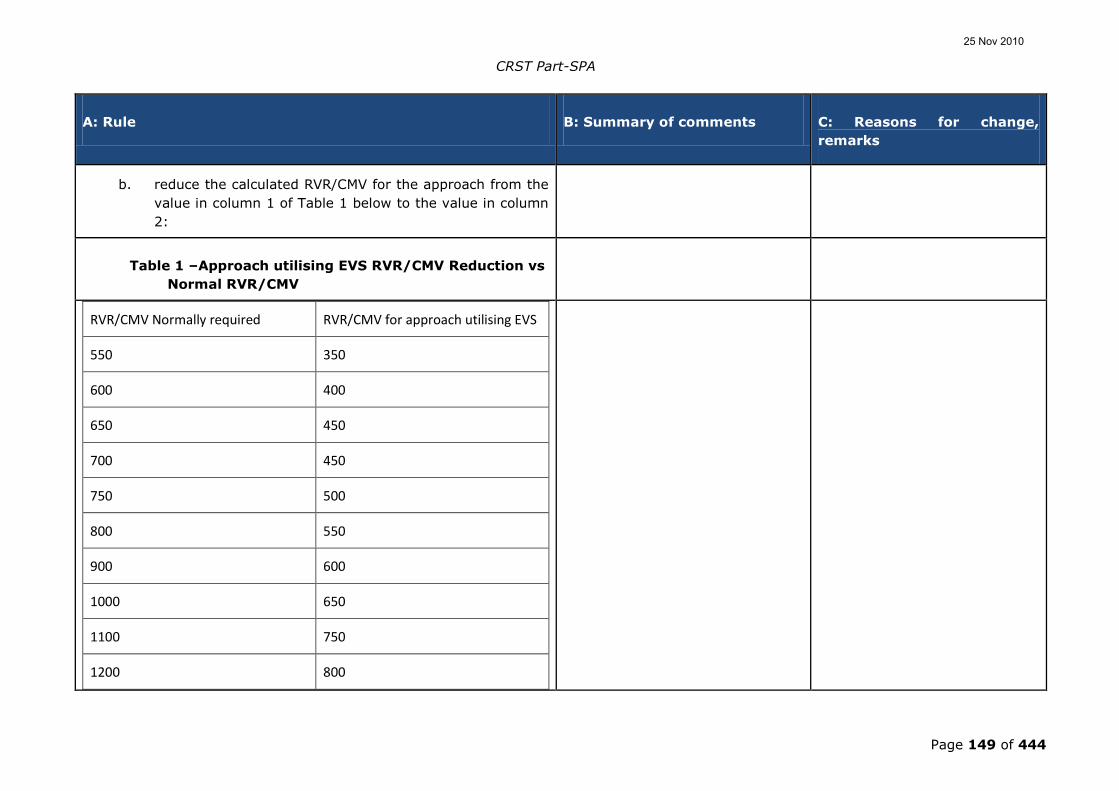
CRST Part-SPA
Page 149 of 444
A: Rule B: Summary of comments C: Reasons for change,
remarks
b. reduce the calculated RVR/CMV for the approach from the
value in column 1 of Table 1 below to the value in column
2:
Table 1 –Approach utilising EVS RVR/CMV Reduction vs
Normal RVR/CMV
RVR/CMV Normally required RVR/CMV for approach utilising EVS
550 350
600 400
650 450
700 450
750 500
800 550
900 600
1000 650
1100 750
1200 800
25 Nov 2010

CRST Part-SPA
Page 150 of 444
A: Rule B: Summary of comments C: Reasons for change,
remarks
1300 900
1400 900
1500 1000
1600 1100
1700 1100
1800 1200
1900 1300
2000 1300
2100 1400
2200 1500
2300 1500
2400 1600
2500 1700
2600 1700
2700 1800
25 Nov 2010

CRST Part-SPA
Page 151 of 444
A: Rule B: Summary of comments C: Reasons for change,
remarks
2800 1900
2900 1900
3000 2000
3100 2000
3200 2100
3300 2200
3400 2200
3500 2300
3600 2400
3700 2400
3800 2500
3900 2600
4000 2600
4100 2700
4200 2800
25 Nov 2010

CRST Part-SPA
Page 152 of 444
A: Rule B: Summary of comments C: Reasons for change,
remarks
4300 2800
4400 2900
4500 3000
4600 3000
4700 3100
4800 3200
4900 3200
5000 3300
2. Paragraph 1 above may only be used for Instrument Landing
System (ILS), Microwave Landing System (MLS), Precision
Approach Radar (PAR), GNSS Landing System (GLS) and
Approaches with Vertical Guidance (APV) Operations with a DH
no lower than 200 feet or an approach flown using approved
vertical flight path guidance to a MDH or DH no lower than 250
feet.
3. A pilot may not continue an approach below 100 feet above
runway threshold elevation for the intended runway, unless at
least one of the visual references specified below is distinctly
visible and identifiable to the pilot without reliance on the
25 Nov 2010

CRST Part-SPA
Page 153 of 444
A: Rule B: Summary of comments C: Reasons for change,
remarks
enhanced vision system:
a. The lights or markings of the threshold; or
b. The lights or markings of the touchdown zone.
GM- OPS.SPA.001.LVO(b)(2) Low visibility operations (LVO) GM1-SPA.LVO.110.
USE OF ENHANCED VISION SYSTEMS (EVS)
1. Introduction
1.1 Enhanced vision systems use sensing technology to improve a
pilot‟s ability to detect objects, such as runway lights or terrain,
which may otherwise not be visible. The image produced from
the sensor and/or image processor can be displayed to the pilot
in a number of ways including use of a head up display. The
systems can be used in all phases of flight and can improve
situational awareness. In particular, infrared systems can
display terrain during operations at night, improve situational
awareness during night and low-visibility taxiing, and may allow
earlier acquisition of visual references during instrument
approaches.
25 Nov 2010

CRST Part-SPA
Page 154 of 444
A: Rule B: Summary of comments C: Reasons for change,
remarks
2. Background to EVS provisions
2.1 The provisions for EVS were developed after an operational
evaluation of two different EVS systems, along with data and
support kindly provided by the FAA. Approaches using EVS
were flown in a variety of conditions including fog, rain and
snow showers, as well as at night to aerodromes located in
mountainous terrain. The infrared EVS performance can vary
depending on the weather conditions encountered. Therefore,
the provisions take a conservative approach to cater for the
wide variety of conditions which may be encountered. It may
be necessary to amend the provisions in the future to take
account of greater operational experience.
2.2 Provisions for the use of EVS during take-off have not been
developed. The systems evaluated did not perform well when
the RVR was below 300 metres. There may be some benefit for
use of EVS during take-off with greater visibility and reduced
lighting; however, such operations would need to be evaluated.
2.3 Provisions have been developed to cover use of infrared
systems only. Other sensing technologies are not intended to
be excluded; however, their use will need to be evaluated to
determine the appropriateness of this, or any other provision.
During the development, it was envisaged what minimum
equipment should be fitted to the aircraft. Given the present
state of technological development, it is considered that a HUD
25 Nov 2010

CRST Part-SPA
Page 155 of 444
A: Rule B: Summary of comments C: Reasons for change,
remarks
is an essential element of the EVS equipment.
2.4 In order to avoid the need for tailored charts for approaches
utilising EVS, it is envisaged that an operator will use AMC
OPS.SPA.001.LVO(b)(2) Table 1 – Approach utilising EVS
RVR/CMV Reduction vs. Normal RVR/CMV to determine the
applicable RVR at the commencement of the approach.
3. Additional operational considerations
3.1 Enhanced vision system equipment should have:
a. a head-up display system (capable of displaying, airspeed,
vertical speed, aircraft attitude, heading, altitude,
command guidance as appropriate for the approach to be
flown, path deviation indications, flight path vector, and
flight path angle reference cue and the EVS imagery);
b. for two-pilot operation, a head-down view of the EVS
image, or other means of displaying the EVS-derived
information easily to the pilot monitoring the progress of
the approach.
1/ A commentator took the view
that having two pilots monitoring
the aircraft trajectory using
information - EVS image - coming
from the same sensor - EVS
infrared camera - is not "safety-
oriented". The commentator
proposes to remove this
paragraph.
1-2/ After a safety assessment
of the original ACJ text, there
was common agreement that
there is no need to modify the
text for the time being.
25 Nov 2010

CRST Part-SPA
Page 156 of 444
A: Rule B: Summary of comments C: Reasons for change,
remarks
2/ Another commentator suggested
that the specific requirements
levied in this paragraph are too
restrictive. A monitoring pilot could
be effective through the use of
other tools than just “a head-down
view of the EVS image, or other
means of displaying the EVS-
derived information
….”Recommendation: For a two-
pilot operation, the monitoring pilot
should have a means of readily
identifying the vertical and
horizontal accuracy of the aircraft
position in relation to the runway.”
If the aircraft is equipped with a radio altimeter, it should be
used only as enhanced terrain awareness during approach
using EVS and should not be taken into account for the
operational procedures development.
1/ This is in contradiction with
OPS.SPA.010.LVO which specifies
that an LVO needs a radio altimeter
to define the DH.
1/ Text deleted because it would
be in contradiction with
SPA.LVO.100.
4. Two-pilot operations
4.1 For operations in RVRs below 550 m, two-pilot operation is
required.
1/ The FAA pointed out that in the
US, there are operators who are
approved to perform operations as
low as CAT II with a single pilot.
The requirement to have two pilots
1/ Noted. Text is maintained as
it transposes the content of EU-
OPS.
25 Nov 2010

CRST Part-SPA
Page 157 of 444
A: Rule B: Summary of comments C: Reasons for change,
remarks
below 550 m would stand in
conflict with this and not allow
operators to take advantage of the
safety benefits afforded by the use
of EVS. An additional inconsistency
with the delineation of a 550 m
restriction is that it would cut into
the realm of the lower-than-
standard CAT I operations.
Recommendation: Recommend
removing paragraph 4 in its
entirety.
4.2 The provision for a head-down view of the EVS image is
intended to cover for multi-pilot philosophy. The pilot not-flying
(PNF) is kept in the „loop‟ and Crew Resource Management
(CRM) does not break down. The PNF can be very isolated from
the information necessary for monitoring flight progress and
decision making if the PF is the only one to have the EVS
image.
1/ A commentator took the view
that having two pilots monitoring
the aircraft trajectory using
information - EVS image - coming
from the same sensor - EVS
infrared camera - is not "safety-
oriented". The commentator
proposes to remove this
paragraph.
1/ After a safety assessment of
the original ACJ text, there was
common agreement that there is
no need to modify the text for
the time being.
AMC OPS.SPA.001.LVO(b)(2)(iii) Low visibility operations
(LVO)
AMC1-SPA.LVO.125
25 Nov 2010

CRST Part-SPA
Page 158 of 444
A: Rule B: Summary of comments C: Reasons for change,
remarks
NORMAL PROCEDURES
1. An operator should establish procedures and instructions to be
used for Low Visibility Take-Off, approaches utilising EVS,
Lower than Standard Category I, Other than Standard Category
II and Category II and III operations. These procedures should
be included in the operations manual and contain the duties of
flight crew members during taxiing, take-off, approach, flare,
the hover, landing, roll-out and missed approach, as
appropriate.
2. An operator should specify the detailed operating procedures
and instructions in the operations manual. The instructions
should be compatible with the limitations and mandatory
procedures contained in the Flight Manual and cover the
following items in particular:
a. Checks for the satisfactory functioning of the aircraft
equipment, both before departure and in flight;
b. Effect on minima caused by changes in the status of the
ground installations and airborne equipment;
c. Procedures for the take-off, approach, flare, hover,
landing, roll-out and missed approach;
25 Nov 2010

CRST Part-SPA
Page 159 of 444
A: Rule B: Summary of comments C: Reasons for change,
remarks
d. Procedures to be followed in the event of failures,
warnings to include HUD/HUDLS/EVS and other non-
normal situations;
e. The minimum visual reference required;
f. The importance of correct seating and eye position;
g. Action which may be necessary arising from a
deterioration of the visual reference;
h. Allocation of crew duties in the carrying out of the
procedures according to 2.a to 2.d and 2.f above, to allow
the pilot-in-command to devote himself mainly to
supervision and decision making;
i. The requirement for all height calls below 200 ft to be
based on the radio altimeter and for one pilot to continue
to monitor the aircraft instruments until the landing is
completed;
j. The requirement for the ILS Sensitive Area to be
protected;
1/ The requirement for the ILS
sensitive area to be protected in
case of Lower than CAT I
operations - is this requirement
applicable down to 200ft, or to the
threshold? In other terms do we
have to protect for the signal on
1/ needs to be addressed in a
multi-disciplinary RM task.
25 Nov 2010

CRST Part-SPA
Page 160 of 444
A: Rule B: Summary of comments C: Reasons for change,
remarks
the visual segment? This is quite
important to know as a CAT I
airport does not have CAT II
holding positions for example. At
several other places this
requirement has been extended to
have LVP to be in force. LVPs cover
more than ILS signal protection.
Finally ILS is not the only system
that can support LVO. The same
requirement should apply to the
other eligible systems. There is no
section that identifies the
requirements when low visibility
procedures are in force. There is no
clarification regarding ATM
procedures for low visibility take-
off and the ones for approach and
landing. Proposed action: Clarify
the exact operation requirement
vis-a-vis the protection needed on
the ground. Take into consideration
other landing system protection
criteria (e.g. MLS). Add a section
for when LVP are in force. Add a
section clarifying LVP applicability:
for take-off or for approach and
landing.
25 Nov 2010

CRST Part-SPA
Page 161 of 444
A: Rule B: Summary of comments C: Reasons for change,
remarks
k. The use of information relating to wind velocity, wind
shear, turbulence, runway contamination and use of
multiple RVR assessments;
l. Procedures to be used for:
i. Lower than Standard Category I;
ii. Other than Standard Category II;
iii. Approaches utilising EVS; and
iv. Practice approaches and landing on runways at which
the full Category II or Category III aerodrome
procedures are not in force;
m. Operating limitations resulting from airworthiness
certification; and
n. Information on the maximum deviation allowed from the
ILS glide path and/or localiser.
GM1 OPS.SPA.001.LVO(b)(2)(iii) Low visibility operations
(LVO)
AMC1-SPA.LVO.125
NORMAL PROCEDURES
25 Nov 2010

CRST Part-SPA
Page 162 of 444
A: Rule B: Summary of comments C: Reasons for change,
remarks
The precise nature and scope of procedures and instructions given
depend upon the airborne equipment used and the cockpit
procedures followed. An operator should clearly define flight crew
member duties during take-off, approach, flare, hover, roll-out and
missed approach in the Operations Manual. Particular emphasis
should be placed on flight crew responsibilities during transition from
non-visual conditions to visual conditions, and on the procedures to
be used in deteriorating visibility or when failures occur. Special
attention should be paid to the distribution of flight deck duties so as
to ensure that the workload of the pilot making the decision to land
or execute a missed approach enables him to devote himself to
supervision and the decision making process.
GM2 OPS.SPA.001.LVO(b)(2)(iii) Low visibility operations
(LVO)
GM1-SPA.LVO.125
NORMAL PROCEDURES – USE OF AUTOLAND SYSTEMS WHEN LOW
VISIBILITY PROCEDURES ARE NOT IN FORCE
1. Introduction
a. Most Instrument Landing System (ILS) installations are
subject to signal interference by either surface vehicles or
aircraft. To prevent this interference ILS critical areas are
established near each localizer and glide slope antenna.
For Category II and III ILS installations, additionally an
1/ The acronym LLZ is not used in
the US or ICAO. LOC is the correct
acronym for localizer.
Recommendation: Recommend
1/ LLZ has been changed into
LOC.
2/ Text revised accordingly.
25 Nov 2010

CRST Part-SPA
Page 163 of 444
A: Rule B: Summary of comments C: Reasons for change,
remarks
ILS sensitive area is established. The critical areas are
restricted from all vehicle or aircraft operation when the
ILS is being used, or at least when an aircraft is inside the
Outer Marker (OM) or equivalent position. At US airports
the Localisor (LLZ) and GP critical areas will be protected
when weather at the airport is reported less than 800 feet
ceiling and/or visibility is less than 2 miles with an aircraft
inside the OM or equivalent position.
changing LLZ to LOC.
2/ Text revision proposed: At US
airports the localisor (LOC) and GP
critical area protection will begin
when weather at the airport is
reported less than 800 feet ceiling
and/or visibility is less than 2 miles
and will be fully protected when the
ceiling is less than 200 feet and/or
the visibility is RVR 2 000 or less,
when an arriving aircraft is inside
the ILS MM.
b. The ILS sensitive area is protected from all surface
vehicles and aircraft when ILS Category II or III
operations are conducted or anticipated. This typically
takes place when landing operations are conducted with
Runway Visual Range (RVR) less than 600 m or with a
ceiling of less than 200 feet. At US airports the sensitive
area is called the “ILS critical area” (not to be confused
with the LLZ or GP critical areas which are smaller). The
US ILS critical area is protected during the corresponding
conditions. The operators need to inform their pilots about
the differences in terminology which are summarised in
the following Table:
EU / EASA US / FAA
25 Nov 2010

CRST Part-SPA
Page 164 of 444
A: Rule B: Summary of comments C: Reasons for change,
remarks
ILS Critical Area(s) LLZ & GP Critical Areas
ILS Sensitive Area ILS Critical Area
c. LVPs on an aerodrome basically have two main objectives:
to prevent collisions involving an aircraft on the
aerodrome and to ensure that the ILS sensitive area is
protected. To find out if LVPs are in force, the pilots need
to contact Air Traffic Control (ATC) or listen to the Air
Traffic Information System (ATIS).
d. When the LVPs are not in force, ILS beam bends may
occur because of vehicle or aircraft interference. Sudden
and unexpected flight control movements may occur at a
very low altitude or during the landing and roll-out when
the autopilot attempts to follow the beam bends. A
Category I ILS is not required to support autoland
operations although it is recognised that some Category I
ILS facilities can support autoland operations. Unless
specifically mentioned in the Aeronautical Information
Publication (AIP), it must be assumed that ILS signals to
Category I runways are not flight inspected below 100
feet Above Ground Level (AGL), and therefore guidance
signal anomalies may be encountered below this altitude
without advance warnings.
2. Auto land operational considerations
25 Nov 2010
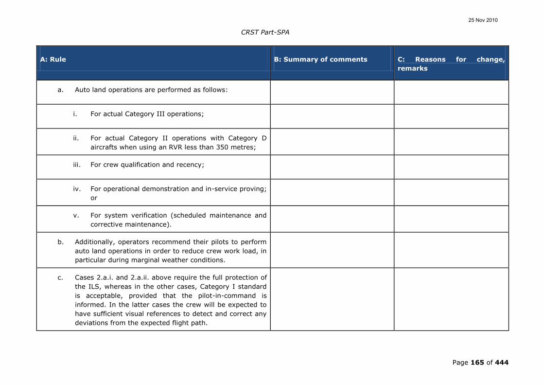
CRST Part-SPA
Page 165 of 444
A: Rule B: Summary of comments C: Reasons for change,
remarks
a. Auto land operations are performed as follows:
i. For actual Category III operations;
ii. For actual Category II operations with Category D
aircrafts when using an RVR less than 350 metres;
iii. For crew qualification and recency;
iv. For operational demonstration and in-service proving;
or
v. For system verification (scheduled maintenance and
corrective maintenance).
b. Additionally, operators recommend their pilots to perform
auto land operations in order to reduce crew work load, in
particular during marginal weather conditions.
c. Cases 2.a.i. and 2.a.ii. above require the full protection of
the ILS, whereas in the other cases, Category I standard
is acceptable, provided that the pilot-in-command is
informed. In the latter cases the crew will be expected to
have sufficient visual references to detect and correct any
deviations from the expected flight path.
25 Nov 2010

CRST Part-SPA
Page 166 of 444
A: Rule B: Summary of comments C: Reasons for change,
remarks
d. For case 2.a.iii. Flight Simulators may be used instead.
e. For case 2.a.iv., a proportion of the number of automatic
landings required by the operators when introducing a
new aircraft type may be done on Cat I facilities for
practical reasons. This reduces the number of auto lands
significantly. As a compensation, this work includes a
requirement to verify the auto land capability for all
combinations of airframe/onboard equipment and runways
and ground equipment. These automatic landings will
need to be done in Category I or II conditions. In order to
reduce the burden on operators and aerodromes, it would
be beneficial if operators using the same type of
airframe/equipment/procedures could take credit for each
other experiences.
3. The problems and potential risks of performing auto-land
operations on ILS facilities or runways not meeting CAT II/III
standards:
a. Where the ILS Auto land system is to be used on an ILS
facility not meeting the CAT II/III standards, it should be
realised that a number of factors may influence the
accuracy of the localiser signal:
i. Since the ILS sensitive area protection is not assured,
other aircraft and vehicles may cause disturbance to
25 Nov 2010

CRST Part-SPA
Page 167 of 444
A: Rule B: Summary of comments C: Reasons for change,
remarks
the localiser signal;
ii. Switch-over time of the ground aids may not be in
accordance with the requirements for Cat III;
iii. The pre-threshold terrain may contain irregularities
which may cause abnormal autopilot behaviour.
b. The quality of the ILS signal may not support an
automatic coupling since this is not a requirement for a
CAT I ILS. In some cases where known inadequacies of
the ILS are present, this will be mentioned in the AIP.
c. Sudden and unexpected flight control movements may
occur at a very low altitude or during the landing and
rollout when the autopilot attempts to follow the beam
bends.
4. Operational procedures to ensure the safety of auto land:
a. when auto land operations are conducted, the operational
procedures should be used fully regardless of the weather
conditions;
b. Flight crews should be alert to the possibility of abnormal
autopilot behaviour and guard the flight controls (control
wheel, rudder pedals, and thrust levers) throughout all
25 Nov 2010

CRST Part-SPA
Page 168 of 444
A: Rule B: Summary of comments C: Reasons for change,
remarks
automatic approaches and landings. They should be
prepared to disconnect the autopilot and manually land or
go-around. Attempts to override the autopilot in lieu of a
disconnect is not recommended due to the forces required
to overpower the autopilot servos;
c. The ATC should be informed about the intention to
conduct an auto land. Such information should not be
taken as a request for or expectation of the protection of
the ILS but is merely given to enhance the possibility for
ATC to inform the flight crew of any known or anticipated
disturbance;
Note: In some States, the hours where practice auto land operations
can expect full protection of the ILS sensitive area, are published
in the AIP.
d. The operator should include the appropriate instructions in
the Operations Manual.
AMC1 OPS.SPA.001.LVO(b)(3) Low visibility operations (LVO) AMC1-SPA.LVO.105-
OPERATIONAL DEMONSTRATION AND DATA
COLLECTION/ANALYSIS
1/ Commentators reminded that at
the Air Safety Committee, the
European Commission, at the
request of several Member States,
has asked EASA to review this
requirement and its practical
1/ Noted.
25 Nov 2010

CRST Part-SPA
Page 169 of 444
A: Rule B: Summary of comments C: Reasons for change,
remarks
implications.
1. Operational Demonstration for aeroplanes
1.1 The purpose of the operational demonstration is to determine
or validate the use and effectiveness of the applicable aircraft
flight guidance systems, including HUDLS if appropriate,
training, flight crew procedures, maintenance programme, and
manuals applicable to the Category II/III programme being
approved.
a. At least 30 approaches and landings should be
accomplished in operations using the Category II/III
systems installed in each aircraft type if the requested
Decision Height (DH) is 50 ft or higher. If the DH is less
than 50 ft, at least 100 approaches and landings should
be accomplished.
1/ A manufacturer recommended
the following text proposal: The
number of approaches or landings
where decision height (DH) is 50 ft
or higher, or where the DH is less
than 50 ft, is approved through
Part-21.
2/ EU-OPS allowed for authorities'
discretion about the amount of
approaches and landings. Proposal:
Add: “unless otherwise approved
by the competent authority”
1/ This operational rule needs
for the time being to be
addressed in the OPS rules. This
does not exclude that, with the
introduction of the OSD, this
provision may be revised.
2/ This has been deleted
because it would be subject to
an AltAMC procedure which
would require an approval of the
competent authority for AOC
holders.
b. If an operator has different variants of the same type of
aircraft utilising the same basic flight control and display
25 Nov 2010

CRST Part-SPA
Page 170 of 444
A: Rule B: Summary of comments C: Reasons for change,
remarks
systems, or different basic flight control and display
systems on the same type of aircraft, the operator should
show that the various variants have satisfactory
performance, but the operator need not conduct a full
operational demonstration for each variant. The number
of approach and landings may be reduced based on the
experience gained by another Community operator using
the same aeroplane type or variant and procedures.
c. If the number of unsuccessful approaches exceeds 5 % of
the total (e.g. unsatisfactory landings, system
disconnects) the evaluation programme should be
extended in steps of at least 10 approaches and landings
until the overall failure rate does not exceed 5 %.
1.2 Data collection for operational demonstrations. Each applicant
should develop a data collection method (e.g. a form to be used
by the flight crew) to record approach and landing
performance. The resulting data and a summary of the
demonstration data should be made available to the competent
authority for evaluation.
1.3 Data analysis. Unsatisfactory approaches and/or automatic
landings should be documented and analysed.
2. Operational demonstration for helicopters
25 Nov 2010

CRST Part-SPA
Page 171 of 444
A: Rule B: Summary of comments C: Reasons for change,
remarks
2.1 The operator should comply with the provisions prescribed in
2.2 below when introducing a helicopter type which is new to
the Community into Category II or III service.
For helicopter types already used for Category II or III
operations in another Member State, the in-service proving
programme in 2.4 should be used instead.
a. Operational reliability. The Category II and III success
rate should not be less than that required by CS-AWO or
its equivalent.
b. Criteria for a successful approach. An approach is
regarded as successful if:
i. The criteria are as specified in CS-AWO or its
equivalent;
ii. No relevant helicopter system failure occurs.
2.2 Data Collection during Airborne System Demonstration -
General
a. An operator should establish a reporting system to enable
checks and periodic reviews to be made during the
operational evaluation period before the operator is
approved to conduct Category II or III operations. The
25 Nov 2010

CRST Part-SPA
Page 172 of 444
A: Rule B: Summary of comments C: Reasons for change,
remarks
reporting system should cover all successful and
unsuccessful approaches, with reasons for the latter, and
include a record of system component failures. This
reporting system should be based upon flight crew reports
and automatic recordings as prescribed in 2.3 and 2.4
below.
b. The recordings of approaches may be made during normal
line flights or during other flights performed by the
operator.
2.3 Data Collection during Airborne System Demonstration –
Operations with DH not less than 50 ft
a. For operations with DH not less than 50 ft, data should be
recorded and evaluated by the operator and evaluated by
the competent authority when necessary.
b. It is sufficient for the following data to be recorded by the
flight crew:
i. FATO and runway used;
ii. Weather conditions;
iii. Time;
25 Nov 2010

CRST Part-SPA
Page 173 of 444
A: Rule B: Summary of comments C: Reasons for change,
remarks
iv. Reason for failure leading to an aborted approach;
v. Adequacy of speed control;
vi. Trim at time of automatic flight control system
disengagement;
vii. Compatibility of automatic flight control system, flight
director and raw data;
viii. An indication of the position of the helicopter relative
to the ILS centreline when descending through 30 m
(100 ft); and
ix. Touchdown position.
c. The number of approaches made during the initial
evaluation should be sufficient to demonstrate that the
performance of the system in actual airline service is such
that a 90 % confidence and a 95 % approach success will
result.
2.4 Data Collection during Airborne System Demonstration –
Operations with DH less than 50 ft or no DH:
25 Nov 2010

CRST Part-SPA
Page 174 of 444
A: Rule B: Summary of comments C: Reasons for change,
remarks
a. For operations with DH less than 50 ft or no DH, a flight
data recorder, or other equipment giving the appropriate
information, should be used in addition to the flight crew
reports to confirm that the system performs as designed
in actual airline service. The following data should be
recorded:
i. Distribution of ILS deviations at 30 m (100 ft), at
touchdown and, if appropriate, at disconnection of
the roll-out control system and the maximum values
of the deviations between those points; and
ii. Sink rate at touchdown.
b. Any landing irregularity should be fully investigated using
all available data to determine its cause.
2.5 In-service proving
An operator fulfilling the provisions of 2.2 above will be deemed
to have met the in-service proving contained in this paragraph.
a. The system should demonstrate reliability and
performance in line operations consistent with the
operational concepts. A sufficient number of successful
landings should be accomplished in line operations,
including training flights, using the auto land and roll-out
25 Nov 2010

CRST Part-SPA
Page 175 of 444
A: Rule B: Summary of comments C: Reasons for change,
remarks
system installed in each helicopter type.
b. The demonstration should be accomplished using a
Category II or Category III ILS. Demonstrations may be
made on other ILS facilities if sufficient data is recorded to
determine the cause of unsatisfactory performance.
c. If an operator has different variants of the same type of
helicopter utilising the same basic flight control and
display systems, or different basic flight control and
display systems on the same type of helicopter, the
operator should show that the variants comply with the
basic system performance criteria, but the operator need
not conduct a full operational demonstration for each
variant.
d. Where an operator introduces a helicopter type which has
already been approved by the competent authority of any
Member State for Category II and/or III operations a
reduced proving programme may be approved.
3. All aircraft
3.1 Continuous Monitoring
25 Nov 2010
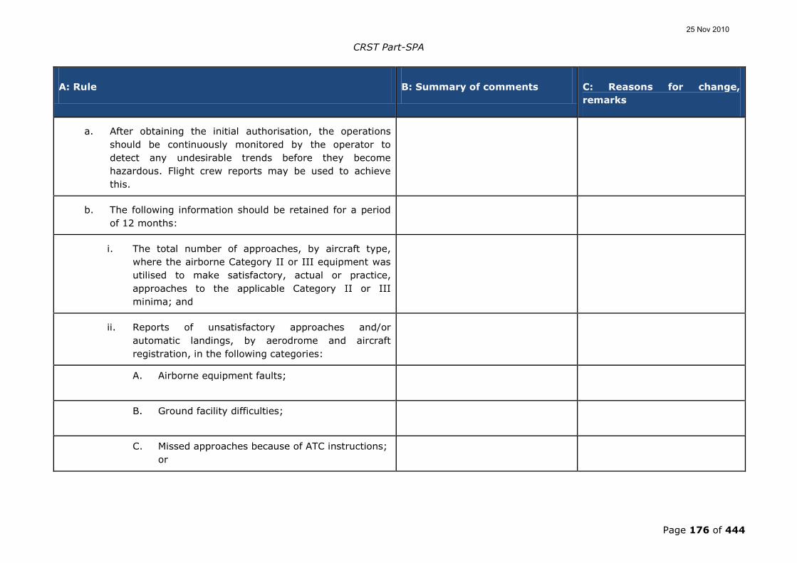
CRST Part-SPA
Page 176 of 444
A: Rule B: Summary of comments C: Reasons for change,
remarks
a. After obtaining the initial authorisation, the operations
should be continuously monitored by the operator to
detect any undesirable trends before they become
hazardous. Flight crew reports may be used to achieve
this.
b. The following information should be retained for a period
of 12 months:
i. The total number of approaches, by aircraft type,
where the airborne Category II or III equipment was
utilised to make satisfactory, actual or practice,
approaches to the applicable Category II or III
minima; and
ii. Reports of unsatisfactory approaches and/or
automatic landings, by aerodrome and aircraft
registration, in the following categories:
A. Airborne equipment faults;
B. Ground facility difficulties;
C. Missed approaches because of ATC instructions;
or
25 Nov 2010

CRST Part-SPA
Page 177 of 444
A: Rule B: Summary of comments C: Reasons for change,
remarks
D. Other reasons.
c. An operator should establish a procedure to monitor the
performance of the automatic landing system or HUDLS to
touchdown performance, as appropriate, of each aircraft.
3.2 Transitional periods
a. Operators with no previous Category II or III experience:
i. An operator without previous Category II or III
operational experience may be approved for Category
II or IIIA operations, having gained a minimum
experience of 6 months of Category I operations on
the aircraft type.
ii. On completing 6 months of Category II or IIIA
operations on the aircraft type the operator may be
approved for Category IIIB operations. When
granting such an approval, the competent authority
may impose higher minima than the lowest applicable
for an additional period. The increase in minima will
normally only refer to RVR and/or a restriction
against operations with no decision height and shall
be selected such that they will not require any
25 Nov 2010

CRST Part-SPA
Page 178 of 444
A: Rule B: Summary of comments C: Reasons for change,
remarks
change of the operational procedures.
b. Operators with previous Category II or III experience:
i. An operator with previous Category II or III
experience may obtain a reduced transition period.
ii. An operator authorised for Category II or III
operations using auto-coupled approach procedures,
with or without auto-land, and subsequently
introducing manually flown Category II or III
operations using a HUDLS should be considered to be
a "New Category II/III operator" for the purposes of
the demonstration period provisions.
3.3 Maintenance of Category II, Category III and LVTO equipment.
Maintenance instructions for the on-board guidance systems
shall be established by the operator, in liaison with the
manufacturer, and included in the operator‟s aircraft
maintenance programme in accordance with Part-M.
3.4 Eligible Aerodromes and Runways 1/ Several commentators strongly
requested to delete these
provisions, which they consider an
administrative burden without
safety benefits.
1/ After an in-depth assessment
of all comments received it was
decided to keep the provision in
the AMC. This would provide
operators the possibility to
25 Nov 2010

CRST Part-SPA
Page 179 of 444
A: Rule B: Summary of comments C: Reasons for change,
remarks
2/ Other commentators took a
contrary position and requested to
clearly state that compliance with
requirement 3.4 is required
continuously throughout the
operation and not only at the time
of the initial application of the Cat
II and Cat III special approval.
propose AltAMC if a safe
operations with other means can
be demonstrated.
a. Each aircraft type/runway combination should be verified
by the successful completion of at least one approach and
landing in Category II or better conditions, prior to
commencing Category III operations.
b. For runways with irregular pre-threshold terrain or other
foreseeable or known deficiencies, each aircraft
type/runway combination should be verified by operations
in standard Category I or better conditions, prior to
commencing Lower than Standard Category I, Category
II, or Other than Standard Category II.
1/ One commentator requested to
add Category III.
1/ CAT III is already addressed
in a.
c. If an operator has different variants of the same type of
aircraft in accordance with 3.4 d. below, utilising the same
basic flight control and display systems, or different basic
flight control and display systems on the same type of
aircraft in accordance with 3.4 d. below, the operator
should show that the variants have satisfactory
operational performance, but the operator need not
25 Nov 2010

CRST Part-SPA
Page 180 of 444
A: Rule B: Summary of comments C: Reasons for change,
remarks
conduct a full operational demonstration for each
variant/runway combination.
d. For the purpose of paragraph 3.4, an aircraft type or
variant of an aircraft type is deemed to be the same
type/variant of aircraft if that type/variant has the same
or similar:
i. level of technology, including the:
A. FGS and associated displays and controls;
B. the FMS and level of integration with the FGS;
C. use of HUDLS.
ii. operational procedures, including:
A. alert height;
B. manual landing /automatic landing;
25 Nov 2010

CRST Part-SPA
Page 181 of 444
A: Rule B: Summary of comments C: Reasons for change,
remarks
C. no decision height operations;
D. use of HUD/HUDLS in hybrid operations.
iii. handling characteristics, including:
A. manual landing from automatic or HUDLS
guided approach;
B. manual go-around from automatic approach;
C. automatic/manual roll out.
e. Operators using the same aircraft type/class or variant of
a type in accordance with 3.4 d. above may take credit
from each other‟s experience and records in complying
with this paragraph.
f. Operators conducting Other than Standard Category II
operations should comply with the requirements of this
section applicable to Category II operations.
AMC2 OPS.SPA.001.LVO(b)(3) Low visibility operations (LVO) AMC2-SPA.LVO.105.
25 Nov 2010

CRST Part-SPA
Page 182 of 444
A: Rule B: Summary of comments C: Reasons for change,
remarks
OPERATIONAL DEMONSTRATION AND DATA
COLLECTION/ANALYSIS
1. General
1.1 Demonstrations may be conducted in line operations or any
other flight where the Operator's procedures are being used.
1.2 In unique situations where the completion of 100 successful
landings could take an unreasonably long period of time due to
factors such as a small number of aircraft in the fleet, limited
opportunity to use runways having Category II/III procedures,
or inability to obtain Air Traffic Services (ATS) sensitive area
protection during good weather conditions, and equivalent
reliability assurance can be achieved, a reduction in the
required number of landings may be considered on a case-by-
case basis. Reduction of the number of landings to be
demonstrated requires a justification for the reduction.
However, at the operator's option, demonstrations may be
made on other runways and facilities. Sufficient information
should be collected to determine the cause of any
unsatisfactory performance (e.g. sensitive area was not
protected).
1.3 If an operator has different variants of the same type of aircraft
utilising the same basic flight control and display systems, or
different basic flight control and display systems on the same
25 Nov 2010

CRST Part-SPA
Page 183 of 444
A: Rule B: Summary of comments C: Reasons for change,
remarks
type/classes of aircraft, the operator should show that the
various variants have satisfactory performance, but the
operator need not conduct a full operational demonstration for
each variant.
1.4 Not more than 30 % of the demonstration flights should be
made on the same runway.
1/ Several commentators stated
that this is not practical at busy
airports and to delete the
provision.
1/ There are no safety related
justifications available to delete
this provision.
2. Data collection for operational demonstrations
2.1 Data should be collected whenever an approach and landing is
attempted utilising the Category II/III system, regardless of
whether the approach is abandoned, unsatisfactory, or is
concluded successfully.
2.2 The data should, as a minimum, include the following
information:
a. Inability to initiate an approach. Identify deficiencies
related to airborne equipment which preclude initiation of
a Category II/III approach.
b. Abandoned approaches. Give the reasons and altitude
above the runway at which approach was discontinued or
the automatic landing system was disengaged.
25 Nov 2010

CRST Part-SPA
Page 184 of 444
A: Rule B: Summary of comments C: Reasons for change,
remarks
c. Touchdown or touchdown and roll-out performance.
Describe whether or not the aircraft landed satisfactorily
(within the desired touchdown area) with lateral velocity
or cross track error which could be corrected by the pilot
or automatic system so as to remain within the lateral
confines of the runway without unusual pilot skill or
technique. The approximate lateral and longitudinal
position of the actual touchdown point in relation to the
runway centreline and the runway threshold, respectively,
should be indicated in the report. This report should also
include any Category II/III system abnormalities which
required manual intervention by the pilot to ensure a safe
touchdown or touchdown and roll-out, as appropriate.
3. Data Analysis
3.1 Unsuccessful approaches due to the following factors may be
excluded from the analysis:
a. ATS Factors. Examples include situations in which a flight
is vectored too close to the final approach fix/point for
adequate localiser and glide slope capture, lack of
protection of ILS sensitive areas, or ATS requests the
flight to discontinue the approach.
b. Faulty Navaid Signals. Navaid (e.g. ILS localiser)
irregularities, such as those caused by other aircraft
25 Nov 2010
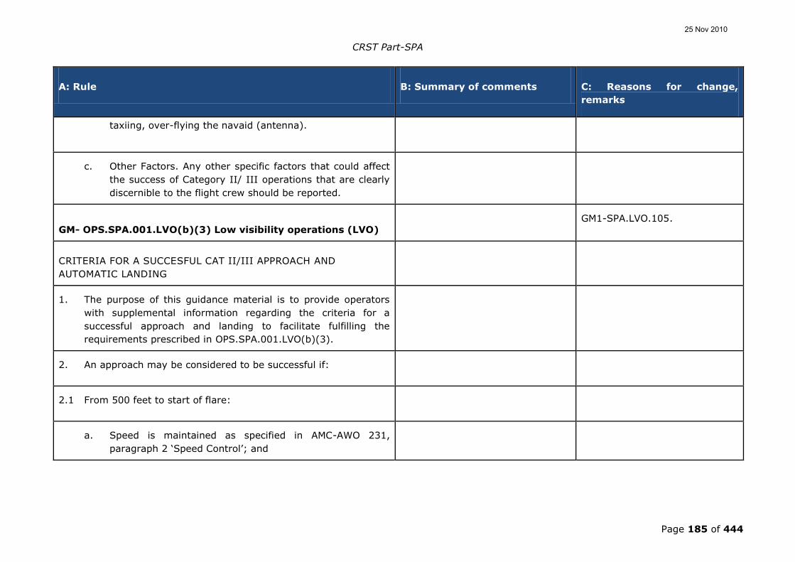
CRST Part-SPA
Page 185 of 444
A: Rule B: Summary of comments C: Reasons for change,
remarks
taxiing, over-flying the navaid (antenna).
c. Other Factors. Any other specific factors that could affect
the success of Category II/ III operations that are clearly
discernible to the flight crew should be reported.
GM- OPS.SPA.001.LVO(b)(3) Low visibility operations (LVO) GM1-SPA.LVO.105.
CRITERIA FOR A SUCCESFUL CAT II/III APPROACH AND
AUTOMATIC LANDING
1. The purpose of this guidance material is to provide operators
with supplemental information regarding the criteria for a
successful approach and landing to facilitate fulfilling the
requirements prescribed in OPS.SPA.001.LVO(b)(3).
2. An approach may be considered to be successful if:
2.1 From 500 feet to start of flare:
a. Speed is maintained as specified in AMC-AWO 231,
paragraph 2 „Speed Control‟; and
25 Nov 2010

CRST Part-SPA
Page 186 of 444
A: Rule B: Summary of comments C: Reasons for change,
remarks
b. No relevant system failure occurs; and
2.2 From 300 feet to DH:
a. no excess deviation occurs; and
b. no centralised warning gives a go-around command (if
installed).
3. An automatic landing may be considered to be successful if:
a. no relevant system failure occurs;
b. no flare failure occurs;
c. no de-crab failure occurs (if installed);
d. longitudinal touchdown is beyond a point on the runway
60 metres after the threshold and before the end of the
touchdown zone lighting (900 metres from the threshold);
e. lateral touchdown with the outboard landing gear is not
outside the touchdown zone lighting edge;
25 Nov 2010

CRST Part-SPA
Page 187 of 444
A: Rule B: Summary of comments C: Reasons for change,
remarks
f. sink rate is not excessive;
g. bank angle does not exceed a bank angle limit; and
h. no roll-out failure or deviation (if installed) occurs.
4. More details can be found in CS-AWO 131, CS-AWO 231 and
AMC-AWO 231.
AMC1 OPS.SPA.020.LVO LVO operating minima 1/ There is a lack of consistency
between the approach taken for
'OPS.GEN.150' and that for 'AMC1
OPS.SPA.020.LVO'. The calculating
methods for 'Aerodrome minima'
have been split between Subpart
GEN and Subpart SPA (with the
exception of LVTO) but the
objective requirements that are
contained in IR OPS.GEN.150 are
only a method of compliance in
AMC1 OPS.SPA.020.LVO. There are
potential issues that arise from
this: Apart from the title, there is
no objective in OPS.SPA.020.LVO
for which this is a method of
compliance (in fact the objective is
CAT.OP.110(a).
1/ This EU-OPS requirement of
1.430 is not limited to SPA
operations and has therefore
been moved to the OP rules.
Moreover, it contains approval
items and has therefore been
moved back as IR.
For NCC/NCO/SPO this AMC is
therefore proposed to be an
AMC to XXX.OP.150.
25 Nov 2010

CRST Part-SPA
Page 188 of 444
A: Rule B: Summary of comments C: Reasons for change,
remarks
itself contained in the AMC). (The
AMC could be promoted to an IR
with the title 'Aerodrome Operating
Minima - General') The text of the
AMC (apart from the substitution of
the word 'shall' with 'should')
contains the rule objective. This
can be seen from the wording (my
underlining) "An operator should
establish, for each aerodrome
planned to be used, aerodrome
operating minima that are not
lower than the values given in...".
Apart from the 'should', this
sentence contains an imperative.
The second paragraph of the AMC
also contains an imperative "Such
minima should not be lower than
the minima that may be
established for such aerodromes by
the State in which the aerodrome
is located, except where specifically
approved by that State". (This is a
Standard in ICAO Annex 6 Part 2,
Chapter 2.2.2.2, and Part 1,
Chapter 4.2.8.1 and might
therefore be a rule and not a
method of compliance.
25 Nov 2010

CRST Part-SPA
Page 189 of 444
A: Rule B: Summary of comments C: Reasons for change,
remarks
GENERAL
1. An operator should establish, for each aerodrome planned to be
used, aerodrome operating minima that are not lower than the
values given in Appendix 1, 2, 3 and 4 to this AMC. The method
of determination of such minima should be included in the
operations manual.
2. Such minima should not be lower than minima that may be
established for such aerodromes by the State in which the
aerodrome is located, except when specifically approved by
that State.
3. The use of HUD, HUDLS or EVS may allow operations with
lower visibilities than normally associated with the aerodrome
operating minima. States which promulgate aerodrome
operating minima may also promulgate regulations for reduced
visibility minima associated with the use of HUD or EVS.
4. In establishing the aerodrome operating minima which will
apply to any particular operation, an operator should take full
account of:
a. the type, performance and handling characteristics of the
aircraft;
25 Nov 2010

CRST Part-SPA
Page 190 of 444
A: Rule B: Summary of comments C: Reasons for change,
remarks
b. the composition of the flight crew, their competence and
experience;
c. the dimensions and characteristics of the FATO‟s/runways
which may be selected for use;
d. the adequacy and performance of the available visual and
non-visual ground aids (see AMC 4 OPS.SPA.020.LVO);
e. the equipment available on the aircraft for the purpose of
navigation and/or control of the flight path, as
appropriate, during the take-off, the approach, the flare,
the hover, the landing, roll-out and the missed approach;
f. the obstacles in the approach, missed approach and the
climb-out areas required for the execution of contingency
procedures and necessary clearance;
g. the obstacle clearance altitude/height for the instrument
approach procedures;
h. the means to determine and report meteorological
conditions; and
i. the flight technique to be used during the final approach.
25 Nov 2010

CRST Part-SPA
Page 191 of 444
A: Rule B: Summary of comments C: Reasons for change,
remarks
Appendix 1 to AMC1 OPS.SPA.020.LVO LVO operating minima 1/ This appendix should be an IR,
not an AMC. Justification: All
requirements of DH/RVR should be
published as Implementing Rules.
2/ LTS allows DH 200 ft with RVR
400 m whereas OTS allows DH
199 ft with RVR 450 m. This looks
inconsistent. Rationale needs to be
checked.
3/ There is no requirement for ILS
type to be published in AIP. How
does an operator find out that the
ILS provided at a specific airport
fully meets the requirement for
lower than Standard CAT I, in
particular the fact that the system
has been flight checked to the
threshold?
AMC1-SPA.LVO.110
1/ It is proposed that the lowest
minima are in IR; the tables,
however, would remain AMC.
2/ Values in the table have been
rectified.
3/ Noted. This will be taken up
when drafting the ATM/ANS
requirements.
LOWER THAN STANDARD CAT I OPERATIONS
1. The decision height should not be lower than the highest of:
a. the minimum decision height specified in the AFM, if
stated; or
25 Nov 2010

CRST Part-SPA
Page 192 of 444
A: Rule B: Summary of comments C: Reasons for change,
remarks
b. the minimum height to which the precision approach aid
can be used without the required visual reference; or
c. the OCH for the category of aircraft; or
d. the decision height to which the flight crew is authorised
to operate; or
e. 200 ft.
2. An ILS/MLS which supports a Lower than Standard Category I
operation should be an unrestricted facility with a straight-in
course (≤ 3º offset) and the ILS should be certificated to:
a. class I/T/1 for operations to a minimum of 450 m RVR; or, 1/ The performance requirement
for the ILS to support CAT I
operations appears to be
excessive. Class I/T/1 requires
Category III localizer performance
to threshold. This will result in an
increased burden on the aerodrome
and facilities organisations.
1/ Noted. This will be reassessed
in a separate rulemaking task.
b. class II/D/2 for operations to less than 450 m RVR.
25 Nov 2010

CRST Part-SPA
Page 193 of 444
A: Rule B: Summary of comments C: Reasons for change,
remarks
Single ILS facilities are only acceptable if Level 2 performance
is provided.
3. Required RVR/CMV.
The lowest minima to be used by an operator for Lower than
Standard Category I operations are stipulated in Table 1 below:
1/ The commentator pointed out
that there are no studies that
would support authorising lower
than standard operations with no
lights (NALS) or basic lights
(BALS). It is recommended that
the columns for BALS and NALS be
removed.
1/ The table is identical with
existing rules. The proposal can
be followed up within a new
Rulemaking task.
Table 1 - Lower than Standard Category I Minimum
RVR/CMV vs. Approach Light System
Lower than Standard Category I Minima
DH (ft) Class of Lighting Facility
FALS IALS BALS NALS
RVR/CMV (Metres)
200 - 210 400 500 600 750
25 Nov 2010

CRST Part-SPA
Page 194 of 444
A: Rule B: Summary of comments C: Reasons for change,
remarks
211 – 220 450 550 650 800
221 – 230 500 600 700 900
231 – 240 500 650 750 1 000
241 – 249 550 700 800 1 100
The visual aids comprise standard runway day markings,
approach lighting, runway edge lights, threshold lights, runway
end lights and, for operations below 450 m, should include
touch-down zone and/or runway centre line lights.
4. Visual reference. A pilot should not continue an approach below
decision height unless visual reference containing a segment of
at least 3 consecutive lights being the centre line of the
approach lights, or touchdown zone lights, or runway centre
line lights, or runway edge lights, or a combination of these is
attained and can be maintained. This visual reference should
include a lateral element of the ground pattern, i.e. an
approach lighting crossbar or the landing threshold or a
barrette of the touchdown zone lighting unless the operation is
conducted utilising an approved HUDLS useable to at least 150
ft.
5. To conduct Lower than Standard Category I operations:
25 Nov 2010

CRST Part-SPA
Page 195 of 444
A: Rule B: Summary of comments C: Reasons for change,
remarks
a. The approach should be flown auto-coupled to an auto-
land; or an approved HUDLS should be used to at least
150ft above the threshold.
1/ Lower than standard CAT I
operations require autoland or
HUDLS to 150 ft. This makes the
use of a localizer over the runway
mandatory if the operator elects to
autoland. The localizer SARPS for
Facility Performance Category III
might not be met in the touch
down zone of the runway. You are
only requiring that the ILS has to
be certified to class I/T/1 which
does not support autoland
operations. Many antenna types
that support CAT I operations are
susceptible to disruptions and it
can be difficult to protect an
autoland (CAT III) sensitive area.
Recommendation: Either do not
require autoland for CAT I
operations; or require that the ILS
be certified and protected to at
least class I/D/1.
1/ Noted. This will be reassessed
in a separate rulemaking task.
b. The aircraft should be certificated in accordance to CS-
AWO to conduct Category II operations;
c. The auto-land system should be approved for Category
25 Nov 2010

CRST Part-SPA
Page 196 of 444
A: Rule B: Summary of comments C: Reasons for change,
remarks
IIIA operations;
d. In service proving requirements should be completed in
accordance with AMC1 OPS.SPA.001.LVO(b)(3) 3.4;
e. Training specified in AMC OPS.LVO.001(b)(1)8. should be
completed, this should include training and checking in a
Flight Simulator using the appropriate ground and visual
aids at the lowest applicable RVR; and
f. The Operator should ensure that Low Visibility procedures
are established and in operation at the intended
aerodrome of landing.
Appendix 2 to AMC1 OPS.SPA.020.LVO LVO operating minima 1/ The commentator pointed out
that there are no studies that
would support authorising lower
than standard operations with no
lights (NALS) or basic lights
(BALS). It is recommended that
the columns for BALS and NALS be
removed.
AMC1-SPA.LVO.110
1/ The table is identical with
existing rules. The proposal can
be followed up within a new
Rulemaking task.
CAT II AND OTHER THAN STANDARD CAT II OPERATIONS
25 Nov 2010

CRST Part-SPA
Page 197 of 444
A: Rule B: Summary of comments C: Reasons for change,
remarks
1. General
a. A Category II operation is a precision instrument approach
and landing using ILS or MLS with:
i. A decision height below 200 ft but not lower than 100
ft; and
ii. A runway visual range of not less than 300 m.
b. An other than Standard Category II operation is a
precision instrument approach and landing using ILS or
MLS which meets facility requirements as established in c.
below with:
i. A decision height below 200 ft but not lower than 100
ft (see Table 2 below); and
ii. A runway visual range of not less than 350/400 m
(see Table 2 below).
1/ Inconsistency with the lowest
minima in the table which are
300/350.
1/ Table 1 refers to CAT II and
not OTS CAT II.
c. The ILS/MLS that supports other than a Standard
Category II operation should be an unrestricted facility
with a straight in course (≤ 3º offset) and the ILS should
be certificated to:
1/ Several commentators pointed
out that Cat II operations refer to a
DH of 200 ft or less. Therefore
stating an ILS requirement for CAT
II operations with a DH of 200 ft or
1-2/ Rectified, only Class II/D/2
is mentioned.
25 Nov 2010

CRST Part-SPA
Page 198 of 444
A: Rule B: Summary of comments C: Reasons for change,
remarks
more does not make sense. Class
II/D/2 implies a requirement for
level 2 performance. Proposed Text
(if applicable): c. The ILS/MLS that
supports other than a Standard
Category II operation should be an
unrestricted facility with a straight
in course (≤ 3º offset) and the ILS
should be certificated to Class
II/D/2.
2/ The AMC indicates that a
straight in course ≤ 3 offset is
acceptable. This would be
unacceptable for low RVR
operations and autoland. The
localizer course could be outside of
the limits of the runway.
Recommendation: Recommend
rewording as follows: The ILS/MLS
that supports other than a
Standard Category II operation
should be an unrestricted facility
with a straight in course aligned
with runway centreline, etc.
i. Class I/T/1 for operations down to 450 m RVR and to
a DH of 200 ft or more; or
25 Nov 2010

CRST Part-SPA
Page 199 of 444
A: Rule B: Summary of comments C: Reasons for change,
remarks
ii. Class II/D/2 for operations in RVRs of less than 450
m or to a DH of less than 200 ft.
Single ILS facilities are only acceptable if Level 2
performance is provided.
2. The decision height should not be lower than the highest of:
a. The minimum decision height specified in the Aircraft
Flight Manual, if stated; or
b. The minimum height to which the precision approach aid
can be used without the required visual reference; or
c. The OCH for the category of aircraft; or
d. The OCH/OCL for the category of helicopter; or
e. The decision height to which the flight crew is authorised
to operate; or
f. 100 ft.
3. Visual reference. A pilot may not continue an approach below
either the Category II or the other than Standard Category II
25 Nov 2010

CRST Part-SPA
Page 200 of 444
A: Rule B: Summary of comments C: Reasons for change,
remarks
decision height determined in accordance with 2. above unless
visual reference containing a segment of at least 3 consecutive
lights being the centre line of the approach lights, or touchdown
zone lights, or FATO/runway centre line lights, or FATO/runway
edge lights, or a combination of these is attained and can be
maintained. This visual reference should include a lateral
element of the ground pattern, i.e. an approach lighting
crossbar or the landing threshold or a barrette of the
touchdown zone lighting unless the operation is conducted
utilising an approved HUDLS to touchdown.
4. The lowest minima to be used by an operator for
a. Category II operations are:
Table 1 – RVR for Cat II Operations vs DH
Category II Minima
DH (ft) RVR
Auto-coupled/Approved HUDLS to below DH*
Aeroplane
Category A, B &
C
Aeroplane
Category D
Helicopters
operated in
Performance
1/ Inconsistencies with the table
for LTS CAT I which would allow
lower RVR minima than OTS CAT
II.
2/ The first column of the bottom
row lists “141 and above.” It is
inconsistent with the text.
Recommendation: Recommend
changing it to “141 to 199” to be
1/ Table values corrected for
OTS CAT II.
2/ Text changed accordingly.
25 Nov 2010

CRST Part-SPA
Page 201 of 444
A: Rule B: Summary of comments C: Reasons for change,
remarks
Class 1
100 – 120 300 m 300 / 350 m** 300 m
121 – 140 400 m 400 m 400 m
141 and above 450 m 450 m 450 m
* The reference to „auto-coupled to below DH/Approved HUDLS‟
in this table means continued use of the automatic flight control
system or the HUDLS down to a height of 80 % of the
applicable DH. Thus airworthiness requirements may, through
minimum engagement height for the automatic flight control
system, affect the DH to be applied.
consistent with paragraph 1. b. i.,
above.
** 300 m may be used for a Category D aeroplane conducting an
auto-land. (See GM2 to Appendix 3 to AMC 1
OPS.SPA.020.LVO).
b. other than Standard Category II operations are:
Table 2 - Other than Standard Category II Minimum
RVR vs. Approach Light System
Other than Standard Category II Minima
DH (ft) Auto land or Approved HUDLS utilised to touchdown
1/ The commentator pointed out
that there are no studies that
would support authorising lower
1/ NALS does not mean that
there are no lights. The table
values have been maintained.
25 Nov 2010

CRST Part-SPA
Page 202 of 444
A: Rule B: Summary of comments C: Reasons for change,
remarks
Class of Lighting Facility
FALS IALS BALS NALS
See AMC6 A OPS.GEN.150 5., 6. and 10. about RVR < 750 m
CAT A - C CAT D CAT A - D CAT A - D CAT A – D
RVR (m)
100 –
120
350 400 450 600 700
121 –
140
400 450 500 600 700
141 –
160
450 500 500 600 750
161 –
199
450 500 550 650 750
The visual aids required to conduct Other than Standard
Category II Operations comprise standard runway day
markings and approach and runway lighting (runway edge
lights, threshold lights, runway end lights). For operations in
RVR of 400 m or less, centre line lights should be available. The
approach light configurations are classified and listed in Table 1
than standard operations with no
lights (NALS) or basic lights
(BALS). It is recommended that
the columns for BALS and NALS be
removed.
25 Nov 2010

CRST Part-SPA
Page 203 of 444
A: Rule B: Summary of comments C: Reasons for change,
remarks
of AMC6 A OPS.GEN.150.
5. To conduct other than Standard Category II operations the
operator should ensure that appropriate Low Visibility
procedures are established and in operation at the intended
aerodrome of landing.
Appendix 3 to AMC1 OPS.SPA.020.LVO LVO operating minima AMC1-SPA.LVO.110.
PRECISION APPROACH - CAT III OPERATIONS
1. General
Category III operations are subdivided as follows:
a. Category III A operations. A precision instrument
approach and landing using ILS or MLS with:
i. A decision height lower than 100 ft; and
ii. A runway visual range not less than 200 m.
25 Nov 2010

CRST Part-SPA
Page 204 of 444
A: Rule B: Summary of comments C: Reasons for change,
remarks
b. Category III B operations. A precision instrument
approach and landing using ILS or MLS with:
i. A decision height lower than 100 ft, or no decision
height; and
ii. A runway visual range lower than 200 m but not less
than 75 m.
Where the decision height (DH) and runway visual range (RVR)
do not fall within the same Category, the RVR will determine in
which Category the operation is to be considered.
2. Decision Height
For operations in which a decision height is used, an operator should
ensure that the decision height is not lower than:
a. The minimum decision height specified in the AFM, if
stated; or
b. The minimum height to which the precision approach aid
can be used without the required visual reference; or
c. The decision height to which the flight crew is authorised
to operate.
25 Nov 2010

CRST Part-SPA
Page 205 of 444
A: Rule B: Summary of comments C: Reasons for change,
remarks
3. No Decision Height Operations
Operations with no decision height may only be conducted if:
a. the operation with no decision height is authorised in the
AFM;
b. the approach aid and the aerodrome facilities can support
operations with no decision height; and
c. the operator has an approval for CAT III operations with
no decision height.
In the case of a CAT III runway it may be assumed that operations
with no decision height can be supported unless specifically
restricted as published in the AIP or NOTAM.
4. Visual reference
4.1 For Category IIIA operations, and for Category IIIB operations
conducted either with fail-passive flight control systems, or with
the use of an approved HUDLS, a pilot may not continue an
approach below the decision height determined in accordance
with 2. above unless a visual reference containing a segment of
at least 3 consecutive lights being the centreline of the
approach lights, or touchdown zone lights, or runway centreline
25 Nov 2010

CRST Part-SPA
Page 206 of 444
A: Rule B: Summary of comments C: Reasons for change,
remarks
lights, or runway edge lights, or a combination of these is
attained and can be maintained.
4.2 For Category IIIB operations conducted either with fail-
operational flight control systems or with a fail operational
hybrid landing system (comprising e.g. a HUDLS) using a
decision height a pilot may not continue an approach below the
Decision Height, determined in accordance with Appendix 1 to
AMC1 OPS.SPA.020.LVO 2., unless a visual reference containing
at least one centreline light is attained and can be maintained.
1/ For CAT IIIB operations with no
decision height there is no
requirement for visual contact with
the runway prior to touchdown.
1/ Text revised accordingly.
5. The lowest required RVR minima to be used by an operator
should be:
Table 1 – RVR for Cat III Operations vs. DH and roll-out
control/guidance system
Category III Minima
Categor
y
Decision Height
(ft)***
Roll-Out Control /
Guidance System
RVR (m)
IIIA < 100 Not required 200*
IIIB < 100 Fail-passive 150*,**
IIIB < 50 Fail-passive 125
1/ The first line of CAT IIIA is set to
200 m. According to ICAO,
through, amdt 33 to Annex 6 part
I, amdt 28 to Annex 6 part II and
amdt 14 to Annex 6 part III,
changing this value to 175 m
should be considered.
1/ The respective amendments
of Annex 6 will be followed up in
a new Rulemaking task.
25 Nov 2010

CRST Part-SPA
Page 207 of 444
A: Rule B: Summary of comments C: Reasons for change,
remarks
IIIB < 50 or no DH Fail-operational**** 75
* For fail-passive operations see GM1 Appendix 3 to AMC1
OPS.SPA.020.LVO.
** For aircraft certificated in accordance with CS-AWO 321(b)(3)
or equivalent.
*** Flight control system redundancy is determined under CS-AWO
by the minimum certificated decision height.
**** The fail operational system referred to may consist of a fail
operational hybrid system. (GM2 Appendix 3 to AMC1
OPS.SPA.020.LVO)
Appendix 4 to AMC1 OPS.SPA.020.LVO LVO operating minima
AERODROME MINIMA – TAKE-OFF MINIMA
Refer to AMC3 OPS.GEN.150 paragraph 3
GM1 Appendix 3 to AMC1 OPS.SPA.020.LVO LVO operating
minima
25 Nov 2010

CRST Part-SPA
Page 208 of 444
A: Rule B: Summary of comments C: Reasons for change,
remarks
CREW ACTIONS IN CASE OF AUTOPILOT FAILURE AT OR BELOW
DECISION HEIGHT IN FAIL-PASSIVE CATEGORY III OPERATIONS
For operations to actual RVR values less than 300 m, a go-around is
assumed in the event of an autopilot failure at or below DH. This
means that a go-around is the normal action. However, the wording
recognises that there may be circumstances where the safest action
is to continue the landing. Such circumstances include the height at
which the failure occurs, the actual visual references, and other
malfunctions. This would typically apply to the late stages of the
flare. In conclusion, it is not forbidden to continue the approach and
complete the landing when the pilot-in-command or the pilot to
whom the conduct of the flight has been delegated, determines that
this is the safest course of action. The operator‟s policy and the
operational instructions should reflect this information.
GM2 Appendix 3 to AMC1 OPS.SPA.020.LVO LVO operating
minima
ESTABLISHMENT OF MINIMUM RVR FOR CATEGORY II AND III
OPERATIONS
1. General
25 Nov 2010

CRST Part-SPA
Page 209 of 444
A: Rule B: Summary of comments C: Reasons for change,
remarks
1.1 When establishing minimum RVR for Category II and III
Operations, operators should pay attention to the following
information which originates in ECAC Doc 17 3rd Edition,
Subpart A. It is retained as background information and, to
some extent, for historical purposes although there may be
some conflict with current practices.
1.2 Since the inception of precision approach and landing
operations various methods have been devised for the
calculation of aerodrome operating minima in terms of decision
height and runway visual range. It is a comparatively
straightforward matter to establish the decision height for an
operation but establishing the minimum RVR to be associated
with that decision height so as to provide a high probability that
the required visual reference will be available at that decision
height has been more of a problem.
1.3 The methods adopted by various States to resolve the DH/RVR
relationship in respect of Category II and Category III
operations have varied considerably. In one instance there has
been a simple approach which entailed the application of
empirical data based on actual operating experience in a
particular environment. This has given satisfactory results for
application within the environment for which it was developed.
In another instance a more sophisticated method was employed
which utilised a fairly complex computer programme to take
account of a wide range of variables. However, in the latter
case, it has been found that with the improvement in the
25 Nov 2010

CRST Part-SPA
Page 210 of 444
A: Rule B: Summary of comments C: Reasons for change,
remarks
performance of visual aids, and the increased use of automatic
equipment in the many different types of new aircraft, most of
the variables cancel each other out and a simple tabulation can
be constructed which is applicable to a wide range of aircraft.
The basic principles which are observed in establishing the
values in such a table are that the scale of visual reference
required by a pilot at and below decision height depends on the
task that he has to carry out, and that the degree to which his
vision is obscured depends on the obscuring medium, the
general rule in fog being that it becomes more dense with
increase in height. Research using flight simulators coupled
with flight trials has shown the following:
a. Most pilots require visual contact to be established about
3 seconds above decision height though it has been
observed that this reduces to about 1 second when a fail-
operational automatic landing system is being used;
b. To establish lateral position and cross-track velocity most
pilots need to see not less than a 3 light segment of the
centre line of the approach lights, or runway centre line,
or runway edge lights;
c. For roll guidance most pilots need to see a lateral element
of the ground pattern, i.e. an approach lighting cross bar,
the landing threshold, or a barrette of the touchdown zone
lighting; and
25 Nov 2010

CRST Part-SPA
Page 211 of 444
A: Rule B: Summary of comments C: Reasons for change,
remarks
d. To make an accurate adjustment to the flight path in the
vertical plane, such as a flare, using purely visual cues,
most pilots need to see a point on the ground which has a
low or zero rate of apparent movement relative to the
aircraft.
e. With regard to fog structure, data gathered in the United
Kingdom over a twenty-year period have shown that in
deep stable fog there is a 90 % probability that the slant
visual range from eye heights higher than 15 ft above the
ground will be less that the horizontal visibility at ground
level, i.e. RVR. There are at present no data available to
show what the relationship is between the Slant Visual
Range and RVR in other low visibility conditions such as
blowing snow, dust or heavy rain, but there is some
evidence in pilot reports that the lack of contrast between
visual aids and the background in such conditions can
produce a relationship similar to that observed in fog.
2. Category II Operations
2.1 The selection of the dimensions of the required visual segments
which are used for Category II operations is based on the
following visual requirements:
a. A visual segment of not less than 90 metres will need to
be in view at and below decision height for pilot to be able
25 Nov 2010

CRST Part-SPA
Page 212 of 444
A: Rule B: Summary of comments C: Reasons for change,
remarks
to monitor an automatic system;
b. A visual segment of not less than 120 metres will need to
be in view for a pilot to be able to maintain the roll
attitude manually at and below decision height; and
c. For a manual landing using only external visual cues, a
visual segment of 225 metres will be required at the
height at which flare initiation starts in order to provide
the pilot with sight of a point of low relative movement on
the ground.
Before using a Category II ILS for landing, the quality of the localiser
between 50 ft and touchdown should be verified.
3. Category III fail passive operations
3.1 Category III operations utilising fail-passive automatic landing
equipment were introduced in the late 1960‟s and it is desirable
that the principles governing the establishment of the minimum
RVR for such operations be dealt with in some detail.
3.2 During an automatic landing the pilot needs to monitor the
performance of the aircraft system, not in order to detect a
failure which is better done by the monitoring devices built into
the system, but so as to know precisely the flight situation. In
the final stages he/she should establish visual contact and, by
25 Nov 2010

CRST Part-SPA
Page 213 of 444
A: Rule B: Summary of comments C: Reasons for change,
remarks
the time he/she reaches decision height, he/she should have
checked the aircraft position relative to the approach or runway
centre-line lights. For this he/she will need sight of horizontal
elements (for roll reference) and part of the touchdown area.
He/she should check for lateral position and cross-track velocity
and, if not within the pre-stated lateral limits, he/she should
carry out a go-around. He/she should also check longitudinal
progress and sight of the landing threshold is useful for this
purpose, as is sight of the touchdown zone lights.
3.3 In the event of a failure of the automatic flight guidance system
below decision height, there are two possible courses of action;
the first is a procedure which allows the pilot to complete the
landing manually if there is adequate visual reference for
him/her to do so, or to initiate a go-around if there is not; the
second is to make a go-around mandatory if there is a system
disconnect regardless of the pilot‟s assessment of the visual
reference available:
a. if the first option is selected then the overriding
requirement in the determination of a minimum RVR is for
sufficient visual cues to be available at and below decision
height for the pilot to be able to carry out a manual
landing. Data presented in Doc 17 showed that a
minimum value of 300 metres would give a high
probability that the cues needed by the pilot to assess the
aircraft in pitch and roll will be available and this should
be the minimum RVR for this procedure.
25 Nov 2010

CRST Part-SPA
Page 214 of 444
A: Rule B: Summary of comments C: Reasons for change,
remarks
b. the second option, to require a go-around to be carried
out should the automatic flight-guidance system fail below
decision height, will permit a lower minimum RVR because
the visual reference requirement will be less if there is no
need to provide for the possibility of a manual landing.
However, this option is only acceptable if it can be shown
that the probability of a system failure below decision
height is acceptably low. It should be recognised that the
inclination of a pilot who experiences such a failure would
be to continue the landing manually but the results of
flight trials in actual conditions and of simulator
experiments show that pilots do not always recognise that
the visual cues are inadequate in such situations and
present recorded data reveal that pilots‟ landing
performance reduces progressively as the RVR is reduced
below 300 metres. It should further be recognised that
there is some risk in carrying out a manual go-around
from below 50 ft in very low visibility and it should
therefore be accepted that if an RVR lower than 300
metres is to be authorised, the flight deck procedure
should not normally allow the pilot to continue the landing
manually in such conditions and the aircraft system should
be sufficiently reliable for the go-around rate to be low.
3.4 These criteria may be relaxed in the case of an aircraft with a
fail-passive automatic landing system which is supplemented by
a head-up display which does not qualify as a fail-operational
system but which gives guidance which will enable the pilot to
25 Nov 2010

CRST Part-SPA
Page 215 of 444
A: Rule B: Summary of comments C: Reasons for change,
remarks
complete a landing in the event of a failure of the automatic
landing system. In this case it is not necessary to make a go-
around mandatory in the event of a failure of the automatic
landing system when the RVR is less than 300 metres.
4. Category III fail operational operations - with a Decision Height
4.1 For Category III operations utilising a fail-operational landing
system with a Decision Height, a pilot should be able to see at
least 1 centre line light.
4.2 For Category III operations utilising a fail-operational hybrid
landing system with a Decision Height, a pilot should have a
visual reference containing a segment of at least 3 consecutive
lights of the runway centre line lights.
5. Category III fail operational operations - with No Decision
Height
5.1 For Category III operations with No Decision Height the pilot is
not required to see the runway prior to touchdown. The
permitted RVR is dependent on the level of aircraft equipment.
5.2 A CAT III runway may be assumed to support operations with
no Decision Height unless specifically restricted as published in
the AIP or NOTAM.
25 Nov 2010

CRST Part-SPA
Page 216 of 444
A: Rule B: Summary of comments C: Reasons for change,
remarks
AMC2 OPS.SPA.020.LVO LVO operating minima
EFFECT ON LANDING MINIMA OF TEMPORARILY FAILED OR
DOWNGRADED GROUND EQUIPMENT
1. Operations with no Decision Height (DH)
1.1 An operator should ensure that, for aircraft authorised to
conduct no DH operations with the lowest RVR limitations, the
following applies in addition to the content of Tables 1, below:
a. RVR. At least one RVR value should be available at the
aerodrome;
b. FATO/Runway lights
i. No FATO/runway edge lights, or no centre lights –
Day – RVR 200 m; Night – Not allowed;
ii. No TDZ lights – No restrictions;
iii. No standby power to FATO/runway lights – Day –
RVR 200 m; Night – not allowed.
25 Nov 2010

CRST Part-SPA
Page 217 of 444
A: Rule B: Summary of comments C: Reasons for change,
remarks
2. Conditions applicable to Table 1:
a. Multiple failures of runway/final approach and take-off
area (FATO) lights other than indicated in Table 1 are not
acceptable.
b. Deficiencies of approach and runway/FATO lights are
treated separately.
c. Category II or III operations. A combination of
deficiencies in FATO/runway lights and RVR assessment
equipment is not allowed.
d. Failures other than Instrument Landing System (ILS)
affect runway visual range (RVR) only and not decision
height (DH).
TABLE 1 - Failed or downgraded equipment - effect on
landing minima
1/ Which rules should be applied
for LTS CAT I and OTS CAT II?
2/ Use table as published in EU-
OPS and add info about CAT 1 and
non-precision approaches.
3/ The tables which describe the
affect of failed or downgraded
equipment on landing minima only
apply to operational requirements.
1/ Needs to be addressed in a
new RM task.
2/ Tables for CAT I and NPA are
in CAT.OP. Tables have been
split between LVO and OP to
keep consistency with other SPA
rules.
3/ This needs to be followed up
in a new Rulemaking task.
25 Nov 2010
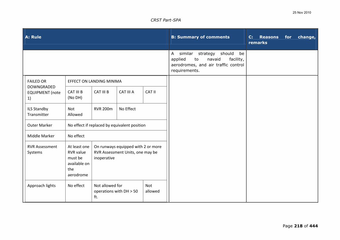
CRST Part-SPA
Page 218 of 444
A: Rule B: Summary of comments C: Reasons for change,
remarks
A similar strategy should be
applied to navaid facility,
aerodromes, and air traffic control
requirements.
FAILED OR
DOWNGRADED
EQUIPMENT (note
1)
EFFECT ON LANDING MINIMA
CAT III B
(No DH)
CAT III B CAT III A CAT II
ILS Standby
Transmitter
Not
Allowed
RVR 200m No Effect
Outer Marker No effect if replaced by equivalent position
Middle Marker No effect
RVR Assessment
Systems
At least one
RVR value
must be
available on
the
aerodrome
On runways equipped with 2 or more
RVR Assessment Units, one may be
inoperative
Approach lights No effect Not allowed for
operations with DH > 50
ft.
Not
allowed
25 Nov 2010

CRST Part-SPA
Page 219 of 444
A: Rule B: Summary of comments C: Reasons for change,
remarks
Approach lights
except the last 210
m
No effect Not
allowed
Approach lights
except the last 420
m
No effect
Standby power for
approach lights
No effect
Edge lights,
threshold lights and
runway end lights
No effect Day - No
effect
Night - Min
RVR 550 m
Day - no
effect
Night –
Not
allowed
Centreline lights Day - RVR
200m
Night - not
allowed
Not
allowed
Day - RVR
300m
Night – RVR
400m
Day - RVR
350m
Night –
RVR 550m
(400m
with
HUDLS or
Auto-land)
25 Nov 2010

CRST Part-SPA
Page 220 of 444
A: Rule B: Summary of comments C: Reasons for change,
remarks
Centreline lights
spacing increased
to 30 m
RVR 150 m No effect
Touch Down Zone
lights
No effect Day - RVR
200m
Night –
RVR 300m
Day - RVR 300m
Night – RVR 550m;
350mwith HUDLS or
auto-land
Taxiway light
system
No effect
Section VSubpart G - Transport of dangerous goods
AMC1- OPS.SPA.001.DG.100(b)(1) Approval to transport
dangerous goods
TRAINING PROGRAMME
1. The operator should indicate for the approval of the training
programme how the training will be carried out. For formal
training courses, the course objectives, the training programme
syllabus/curricula and examples of the written examination to
be undertaken should be included.
25 Nov 2010

CRST Part-SPA
Page 221 of 444
A: Rule B: Summary of comments C: Reasons for change,
remarks
2. Instructors should have knowledge of training techniques as
well as in the field of transport of dangerous goods by air so
that the subject is covered fully and questions can be
adequately answered.
3. Training intended to give general information and guidance
may be by any means including hand-outs, leaflets, circulars,
slide presentations, videos, computer based training, etc.,
and may take place on-the-job or off-the-job. The person being
trained should receive an overall awareness of the subject. This
training should include a written, or oral or computer based
examination covering all areas of the training programme,
showing that a required minimum level of knowledge has been
acquired.
1 comment (IND): The text does
not specifically mention computer-
based training or computer-based
exam as a possibility and these
should be included to avoid doubt.
Text amended to refer to
computer-based training and
computer-based examinations.
4. Training intended to give an in-depth and detailed appreciation
of the whole subject or particular aspects of it should be by
formal training courses, which should include a written
examination, the successful passing of which will result in the
issue of the proof of qualification. The course may be by means
of tuition or as a self-study program or a mixture of both. The
person being trained should gain knowledge so as to be able to
apply the detailed requirements of the Technical Instructions.
5. Training in emergency procedures should include as a
minimum:
25 Nov 2010

CRST Part-SPA
Page 222 of 444
A: Rule B: Summary of comments C: Reasons for change,
remarks
a. fFor personnel other than crew members:
i. Ddealing with damaged or leaking packages; and
ii. oOther actions in the event of ground emergencies
arising from dangerous goods;
b. Ffor flight crew members:
i. aActions in the event of emergencies in flight
occurring in the passenger cabin or in the cargo
compartments; and
ii. tThe notification to Air Traffic ServicesATS should an
in-flight emergency occur.
c. fFor crew members other than flight crew members:
i. dDealing with incidents arising from dangerous goods
carried by passengers; or
ii. dDealing with damaged or leaking packages in flight.
25 Nov 2010

CRST Part-SPA
Page 223 of 444
A: Rule B: Summary of comments C: Reasons for change,
remarks
6. Training should be conducted at intervals of not longer than 2
two years.
This paragraph received 25
comments (IND): It was proposed
to extend this requirement to 5
years.
Not accepted. This proposed
amendment would not be in
compliance with Part 1; Chapter
4.2.3 of the T.I. which has been
a requirement for many years.
AMC1-OPS.SPA.001.DG.100(b)(2)(ii) Approval to transport
dangerous goods
ACCEPTANCE OF DANGEROUS GOODS
1. An The operator should not accept dangerous goods unless:
a. the package, overpack or freight container has been
inspected in accordance with the acceptance procedures in
the Technical Instructions;
b. except when otherwise specified in the Technical
Instructions, they are accompanied by two copies of a
dangerous goods transport document or the information
applicable to the consignment is provided in
electronic form; and
Provision needs to be included for
electronic transfer of data.
Amended to reflect amendments
to the Technical Instructions to
specifically permit the use of
electronic transfer of data.
c. the English language is used for:
25 Nov 2010

CRST Part-SPA
Page 224 of 444
A: Rule B: Summary of comments C: Reasons for change,
remarks
i. package marking and labelling; and
ii. the dangerous goods transport document
in addition to any other language requirements.
2. An The operator or his/her handling agent should use an
acceptance check list which allows for:
a. all relevant details to be checked; and
b. the recording of the results of the acceptance check by
manual, mechanical or computerised means.
AMC1-OPS.SPA.001.DG.100(b)(2)(iv) Approval to transport
dangerous goods
PROVISION OF INFORMATION IN THE EVENT OF AN IN-FLIGHT
EMERGENCY
If an in-flight emergency occurs the pilot-in-command/commander
should, as soon as the situation permits, inform the appropriate air
traffic servicesATS unit of any dangerous goods carried as cargo on
board the aircraft as specified in the Technical Instructions.
25 Nov 2010

CRST Part-SPA
Page 225 of 444
A: Rule B: Summary of comments C: Reasons for change,
remarks
AMC OPS.SPA.001.DG(b)(2)(v) Approval to transport
dangerous goods
REMOVAL OF CONTAMINATION
Text deleted as generally, text
from the TI has been repeated if
it contains obligations for the
operator. Where there is general
text that is also contained in the
Technical Instructions, this has
not been repeated.
1. An operator should ensure that:
a. Any contamination found as a result of resulting from the
leakage from or damage to articles or packages containing
dangerous goods is removed without delay and steps are taken to
nullify any hazard as specified in the Technical Instructions; and
b. An aircraft which has been contaminated by radioactive
materials is immediately taken out of service and not returned
until the radiation level at any accessible surface and the non-
fixed contamination are not more than the values specified in
the Technical Instructions.
2. In the event of a non-compliance with any limit in the
Technical Instructions applicable to radiation level or contamination,
a. the operator should:
25 Nov 2010

CRST Part-SPA
Page 226 of 444
A: Rule B: Summary of comments C: Reasons for change,
remarks
i. ensure the shipper is informed if the non-compliance is
identified during transport;
ii. take immediate steps to mitigate the consequences of the
non-compliance;
iii. communicate the non-compliance to the shipper and relevant
competent authority(ies), respectively, as soon as practicable and
immediately whenever an emergency situation has developed or is
developing;
b. the operator should also, within the scope of his
responsibilities:
i. investigate, the non-compliance and its causes,
circumstances and consequences;
ii. take appropriate action, to remedy the causes and
circumstances that led to the non-compliance and to prevent a
recurrence of similar circumstances that led to the non-compliance;
iii. communicate to the relevant competent authority(ies) on the
causes of the non-compliance and on corrective or preventative
actions taken or to be taken.
25 Nov 2010
CRST Part-SPA
Page 227 of 444
A: Rule B: Summary of comments C: Reasons for change,
remarks
AMC OPS.SPA.001.DG(b)(2)(vii) Approval to transport dangerous
goods
Inspection for Damage, Leakage or Contamination
The text from EU/JAR-OPS
1/3.1200(a)(2) seems to have
been omitted.
Text deleted as unnecessary
repetition of text contained in
the Technical Instructions.
The TI contains this requirement
in 7.3.1.2.
An operator should ensure that:
1. Packages, overpacks and freight containers are inspected for
evidence of leakage or damage immediately prior to loading on an
aircraft, as specified in the Technical Instructions;
2. Leaking or damaged packages, overpacks or freight
containers are not loaded on an aircraft;
3. Any package of dangerous goods found on an aircraft and
which appears to be damaged or leaking is removed or
arrangements made for its removal by an appropriate authority or
organisation. In this case the remainder of the consignment shall be
inspected to ensure it is in a proper condition for transport and that
no damage or contamination has occurred to the aircraft or its load;
and
4. Packages, overpacks and freight containers are inspected for
signs of damage or leakage upon unloading from a aircraft and, if
there is evidence of damage or leakage, the area where the
dangerous goods were stowed is inspected for damage or
25 Nov 2010

CRST Part-SPA
Page 228 of 444
A: Rule B: Summary of comments C: Reasons for change,
remarks
contamination.
GM1-OPS.SPA.001.DG.100(b)(1) Approval to transport
dangerous goods
PERSONNEL
Personnel include all persons involved in the transport of dangerous
goods, whether they are employees of the operator or not.
AMC OPS.SPA.040.DG(b) Dangerous goods information and
documentation
Information to Passengers and Other Persons
The provision of information to
passengers and at cargo
acceptance points applies to all
operators and should be in the
relevant GEN Subparts.
Section moved to become GM to
the relevant GEN Subparts.
1. An operator should ensure that information is promulgated as
required by the Technical Instructions so that passengers are
warned as to the types of goods which they are forbidden from
transporting aboard an aircraft; and
2. An operator and, where applicable, his handling agent should
ensure that notices are provided at acceptance points for cargo
giving information about the transport of dangerous goods.
Delete „and, where applicable, his
handling agent‟ since handling
agents are not subject to this
document.
The text „and, where applicable,
his handling agent‟ will be
deleted from the re-positioned
text.
25 Nov 2010

CRST Part-SPA
Page 229 of 444
A: Rule B: Summary of comments C: Reasons for change,
remarks
AMC1-OPS.SPA.040.DG.105(ca) Dangerous goods information
and documentation
INFORMATION TO THE PILOT-IN-COMMAND/COMMANDER
If the volume of information provided to the pilot-in-
command/commander is such that it would be impracticable to
transmit it in the event of an in-flight emergency, a summary of the
information should be provided to the pilot-in-
command/commander by the operator, containing at least the
quantities and class or division of the dangerous goods in each cargo
compartment.
Subpart D - Section VI - Helicopter operations without an
assured safe forced landing capability
(MS=3; IND=1; INDIV=58 – these
comments include multiple
repeated comments from a number
of individuals and cannot therefore
be considered as representative)
A number of comments relate SFL
to:
Noted.
In order to address a large
number of comments, the
following four responses have
been gathered together in one
general response and the
commentators are enumerated
by numbers in the adjacent cell.
25 Nov 2010

CRST Part-SPA
Page 230 of 444
A: Rule B: Summary of comments C: Reasons for change,
remarks
1. AW,
2. the inclusion of helicopter with
reciprocal engines,
3. the applicability of Appendix
3.005(e),
4. mountain operations and
mountain rescue.
This is mainly because it is in
Subpart SPA and therefore within
the scope of all of the operational
areas.
Each of the four subjects are
dealt with immediately below:
1. SFL is restricted to CAT
except that it should be applied
to AW when carrying passengers
(i.e. neither crew members nor
aerial task specialists). For that
reason, it has been withdrawn
from Subpart SPA and put back
into the performance Subparts
of CAT. The exception is a
special case of AW with
passengers and represents an
operational limitation unless the
UMS is fitted – this will put the
AW with passengers on the
25 Nov 2010

CRST Part-SPA
Page 231 of 444
A: Rule B: Summary of comments C: Reasons for change,
remarks
same footing as those aircraft
operating in a hostile
environment in accordance with
the requirements of Appendix 1
to JAR-OPS 3.005(f). AW
operations without the carriage
of passengers will not be
required to have a safe-forced-
landing capability.
2. The exclusion of reciprocal
engine helicopter from the
hostile environment appendix is
being addressed as the subject
of a future regulatory task.
3. The SFL concept of CAT is
dependent upon engine
reliability of 1:100 000 per flight
hour and an exposure to an
accident in limited phases of
flight that reduce the overall
exposure to 5 x 10⁻⁸; such
exceptions that are permitted
are related to operational areas
where it is impractical to apply
(mountain areas) or where
legacy operations should be
25 Nov 2010

CRST Part-SPA
Page 232 of 444
A: Rule B: Summary of comments C: Reasons for change,
remarks
maintained (remote Arctic
areas) because the expense of
twins could not be tolerated and
alternative surface transport
introduces greater risk.
JAR-OPS 3.005(e) has been
transposed into CAT.POL.H.420.
4. The issue with mountain
rescue is well understood and is
examined and discussed in TGL
43; the recommendations in TGL
will be considered by EASA and
a solution sought in a future
regulatory task.
GM OPS.SPA.001.SFL(b) Operations without an assured
safe forced landing capability
HELICOPTER FLIGHT MANUAL LIMITATIONS
The approved performance data contained in the Helicopter Flight
Manual should be used to determine compliance with the
requirements of the appropriate performance class, supplemented as
necessary with other data acceptable to the competent authority as
may be prescribed in the relevant requirements. When applying the
The text of GM
OPS.SPA.001.SFL(b) belongs to
OPS.CAT.360.H; it has nothing to
do with operations without SFL. It
would better if it were (b) of the IR
Accepted
The JAR-OPS 3 text will be
reinstated.
25 Nov 2010

CRST Part-SPA
Page 233 of 444
A: Rule B: Summary of comments C: Reasons for change,
remarks
factors prescribed for the appropriate performance class, account
should be taken of any operational factors already incorporated in
the Helicopter Flight Manual performance data to avoid double
application of these factors.
above.:
AMC OPS.SPA.001.SFL(b)(1) and (b)(2) Operations
without an assured safe forced landing capability
POWERPLANT RELIABILITY STATISTICS
1. Except in the case of new engines, power plant reliability
should show sudden power loss from the set of in-flight
shutdown (IFSD) events not exceeding 1 per 100,000 engine
hours in a 5 year moving window. A rate in excess of this
value, but not exceeding 3 per 100,000 engine hours, may be
accepted by the competent authority after an assessment
showing an improving trend.
One commentator suggested that
the text for the improving rate
should be removed and that
alternative wording (less liberal) be
used in the assessment.
Noted.
This system (which was
accepted by all manufacturers)
is being used at this time and
has resulted in the production of
these data for the first time.
Before this AMC, there was no
provision for, and sharing of,
data.
The methodology has been
transposed from JAR-OPS 3; any
change should be the subject of
a new Rulemaking proposal.
2. New engines should be assessed on a case-by-case basis.
25 Nov 2010

CRST Part-SPA
Page 234 of 444
A: Rule B: Summary of comments C: Reasons for change,
remarks
3. After the initial assessment, updated statistics should be
periodically reassessed; any adverse sustained trend will
require an immediate evaluation to be accomplished by the
operator in consultation with the competent authority and the
manufacturers concerned. The evaluation may result in
corrective action or operational restrictions being applied.
GM OPS.SPA.001.SFL(b)(1) and (b)(2) Operations
without an assured safe forced landing capability
DETERMINATION OF SUDDEN POWER LOSS RATE This a requirement for the
manufacturer and should be
deleted here.
Not accepted
This system (which was
accepted by all manufacturers)
is being used at this time and
has resulted in the production of
these data for the first time.
Before this AMC, there was no
provision for, and sharing of,
data.
Applicability factor‟ and the
„assumptions made on the
efficiency of corrective actions‟ are
subjective items and should not be
used in the primary statistical
analysis. Consequently, the text
Noted
This system (which was
accepted by all manufacturers)
is being used at this time and
has resulted in the production of
these data for the first time.
25 Nov 2010

CRST Part-SPA
Page 235 of 444
A: Rule B: Summary of comments C: Reasons for change,
remarks
should be amended as shown
below, with deleted text struck
through and additional text in bold.
Before this AMC, there was no
provision for, and sharing of,
data.
The methodology has been
transposed from JAR-OPS 3; any
change should be the subject of
a new proposal.
1. The purpose of this paragraph is to provide guidance on how
the in-service power plant sudden power loss rate is
determined.
a. Share of roles between the helicopter and engine Type
Certificate Holders (TCH).
i. The provision of documents establishing the in-
service sudden power loss rate for the
helicopter/engine installation; the interface with the
operational authority of the State of Design should be
the Engine TCH or the Helicopter TCH depending on
the way they share the corresponding analysis work.
ii. The Engine TCH should provide the Helicopter TCH
with a document including: the list of in-service
power loss events, the applicability factor for each
event (if used), and the assumptions made on the
efficiency of any corrective actions implemented (if
25 Nov 2010

CRST Part-SPA
Page 236 of 444
A: Rule B: Summary of comments C: Reasons for change,
remarks
used);
iii. The Engine or Helicopter TCH should provide the
operational authority of the State of Design or, where
this authority does not take responsibility, the
competent authority, with a document that details
the calculation results - taking into account:
1 MS comments that there is no
reason for having “where this
authority does not take
responsibility”. EASA has to take
the responsibility for that because
EASA is responsible for the
airworthiness and to ensure that
the eligibility of helicopters will be
the same throughout Europe.
Not accepted
The TCH (for engine or
helicopter) may not be within
the jurisdiction of EASA (in fact
most are not). This text makes
provisions for this fact and
provides a method of
provisioning of the document so
that reliability may be assessed.
A. the events caused by the engine and the events
caused by the engine installation;
B. the applicability factor for each event (if used),
the assumptions made on the efficiency of any
corrective actions implemented on the engine
and on the helicopter (if used); and
C. the calculation of the power plant power loss
rate.
b. Documentation.
The following documentation should be updated every year:
25 Nov 2010

CRST Part-SPA
Page 237 of 444
A: Rule B: Summary of comments C: Reasons for change,
remarks
i. The document with detailed methodology and
calculation as distributed to the authority of the State
of Design;
ii. A summary document with results of computation as
made available on request to any competent
authority;
iii. A Service Letter establishing the eligibility for such
operation and defining the corresponding required
configuration as provided to the operators.
c. Definition of the “sudden in-service power loss”.
The sudden in-service power loss is an engine power loss:
i. larger than 30 % of the take-off power;
ii. occurring during operation; and
iii. without the occurrence of an early intelligible warning
to inform and give sufficient time for the pilot to take
any appropriate action.
25 Nov 2010

CRST Part-SPA
Page 238 of 444
A: Rule B: Summary of comments C: Reasons for change,
remarks
d. Data base documentation.
Each power loss event should be documented, by the engine and/or
helicopter TCH‟s, as follows:
i. incident report number;
ii. engine type;
iii. engine serial number;
iv. helicopter serial number;
v. date;
vi. event type (demanded IFSD, un-demanded IFSD);
vii. presumed cause;
viii. applicability factor when used; and
25 Nov 2010

CRST Part-SPA
Page 239 of 444
A: Rule B: Summary of comments C: Reasons for change,
remarks
ix. reference and assumed efficiency of the corrective
actions that will have to be applied (if any).
e. Counting methodology.
Various methodologies for counting engine power loss rate have
been accepted by authorities. The following is an example of one of
these methodologies:
i. The events resulting from:
A. unknown causes (wreckage not found or totally
destroyed, undocumented or unproven
statements); or
B. where the engine or the elements of the engine
installation have not been investigated (for
example when the engine has not been returned
by the customer); or
C. an unsuitable or non representative use
(operation or maintenance) of the helicopter or
the engine;
are not counted as engine in-service sudden power loss and the
applicability factor is 0 %.
25 Nov 2010

CRST Part-SPA
Page 240 of 444
A: Rule B: Summary of comments C: Reasons for change,
remarks
ii. The events caused by:
A. the engine or the engine installation; or
B. the engine or helicopter maintenance, when the
applied maintenance was compliant with the
Maintenance Manuals;
are counted as engine in-service sudden power loss and the
applicability factor is 100 %.
iii. For the events where the engine or an element of the
engine installation has been submitted to
investigation which did not allow defining a presumed
cause, the applicability factor is 50 %.
f. Efficiency of corrective actions.
The corrective actions made by the engine and helicopter
manufacturers on the definition or maintenance of the engine or its
installation could be defined as mandatory for specific commercial air
transport (CAT) operations. In this case, the associated reliability
improvement could be considered as mitigating factor for the event.
A factor defining the efficiency of the corrective action could be
applied to the applicability factor of the concerned event.
25 Nov 2010

CRST Part-SPA
Page 241 of 444
A: Rule B: Summary of comments C: Reasons for change,
remarks
g. Method of calculation of the power plant power loss rate.
The detailed method of calculation of the power plant power loss rate
should be documented by engine or helicopter TCH and accepted by
the relevant authority.
AMC OPS.SPA.001.SFL(b)(3)(ii) Operations without an
assured safe forced landing capability
SITE SPECIFIC PROCEDURES
1. Site specific procedures should be established and included in
the Operations Manual to minimise the period during which
there would be danger to helicopter occupants and persons on
the surface in the event of a power unit failure during take-off
and landing at a public interest site.
1 IND comments that it would not
be possible to capture the data for
all of its landing sites.
Not accepted.
This text comes originally from
JAR-OPS 3.005(i) and is
specifically related to public
interest sites. These are sites
within cities that do not meet
the criteria for operations in PC1
and are therefore alleviated.
To ensure that all appropriate
precautions are taken, it
becomes an obligation upon the
operator to capture the main
dangers and the mitigated
procedures. This is not an
25 Nov 2010

CRST Part-SPA
Page 242 of 444
A: Rule B: Summary of comments C: Reasons for change,
remarks
arduous task and merely reflects
conditions of the SMS to reduce
risk.
2. Part C of the Operations Manual should therefore contain for
each public interest site a diagram or annotated photograph
showing the main aspects, the dimensions, the non-
conformance with performance class 1 requirements, the main
risks and the contingency plan should an incident occur.
Should state: 2. Part C of the
operations manual should therefore
contain for each public interest site
a diagram or annotated photograph
showing the main aspects, the
dimensions, the non-conformance
with performance class 1
requirements, the main risks and
the contingency plan should an
incident occur or a reference where
such information can be found. It is
acceptable that such information
are published in an electronic
format.
Not accepted.
It is not necessary for the OM to
be in one volume, it may be in
several. The main consideration
is that it is available in flight.
A reference would not be
sufficient because it does not
specify that it has to be carried
in flight.
AMC OPS.SPA.001.SFL(b)(4) and (b)(5) Operations
without an assured safe forced landing capability
(
SET OF CONDITIONS TO BE IMPLEMENTED TO OBTAIN AND
MAINTAIN THE APPROVAL
25 Nov 2010

CRST Part-SPA
Page 243 of 444
A: Rule B: Summary of comments C: Reasons for change,
remarks
To obtain an approval under this section, an operator conducting
operations without an assured safe forced landing capability should
implement the following:
1. Attain and then maintain the helicopter/engine modification
standard defined by the manufacturer that has been designated
to enhance reliability during the take-off and landing phases.
2. Conduct the preventive maintenance actions recommended by
the helicopter or engine manufacturer as follows:
a. Engine oil spectrometric and debris analysis - as
appropriate;
b. Engine trend monitoring, based on available power
assurance checks;
c. Engine vibration analysis (plus any other vibration
monitoring systems where fitted).
d. Oil consumption monitoring.
3. The Usage Monitoring System should fulfil at least the
following:
a. Recording of the following data:
25 Nov 2010

CRST Part-SPA
Page 244 of 444
A: Rule B: Summary of comments C: Reasons for change,
remarks
i. Date and time of recording, or a reliable means of
establishing these parameters;
ii. Amount of flight hours recorded during the day plus
total flight time;
iii. N1 (gas producer RPM) cycle count;
iv. N2 (power turbine RPM) cycle count (if the engine
features a free turbine);
v. Turbine temperature exceedance: value, duration;
vi. Power-shaft torque exceedance: value, duration (if a
torque sensor is fitted); and
vii. Engine shafts speed exceedance: value, duration.
b. Data storage of the above parameters, if applicable,
covering the maximum flight time in a day, and not less
than 5 flight hours, with an appropriate sampling interval
for each parameter.
c. The system should include a comprehensive self-test
function with a malfunction indicator and a detection of
25 Nov 2010

CRST Part-SPA
Page 245 of 444
A: Rule B: Summary of comments C: Reasons for change,
remarks
power-off or sensor input disconnection.
d. A means should be available for downloading and analysis
of the recorded parameters. Frequency of downloading
should be sufficient to ensure data is not lost through
over-writing.
e. The analysis of parameters gathered by the usage
monitoring system, the frequency of such analysis and
subsequent maintenance actions should be described in
the maintenance documentation.
f. The data should be stored in an acceptable form and
accessible to the authority, for at least 24 months.
4. Include take-off and landing procedures in the operations
manual, where they do not already exist in the Helicopter Flight
Manual.
5. Establish training for flight crew which should include the
discussion, demonstration, use and practice of the techniques
necessary to minimise the risks;
1 manufacturer comments that:
the requirement is already covered
by OPS.SPA.001.SFL (b)(6). So this
requirement should not be listed as
one of the set of conditions
requested by OPS.SPA.001.SFL (5).
Noted.
All such anomalies are
addressed by aligning the text
with JAR-OPS.
25 Nov 2010
CRST Part-SPA
Page 246 of 444
A: Rule B: Summary of comments C: Reasons for change,
remarks
6. Report to the manufacturer any loss of power control, engine
shutdown (precautionary or otherwise) or power unit failure for
any cause (excluding simulation of power unit failure during
training). The content of each report should provide:
a. Date and time;
b. Operator (and Maintenance organisations where relevant);
c. Type of helicopter and description of operations;
d. Registration and serial number of airframe;
e. Engine type and serial number;
f. Power unit modification standard where relevant to
failure;
g. Engine position;
h. Symptoms leading up to the event.
25 Nov 2010

CRST Part-SPA
Page 247 of 444
A: Rule B: Summary of comments C: Reasons for change,
remarks
i. Circumstances of power unit failure including phase of
flight or ground operation;
j. Consequences of the event;
k. Weather/environmental conditions;
l. Reason for power unit failure – if known;
m. In case of an In Flight Shut Down (IFSD), nature of the
IFSD (Demanded/Un-demanded);
n. Procedure applied and any comment regarding engine
restart potential;
o. Engine hours and cycles (from new and last overhaul);
p. Airframe flight hours;
q. Rectification actions applied including, if any, component
changes with part number and serial number of the
removed equipments; and
25 Nov 2010
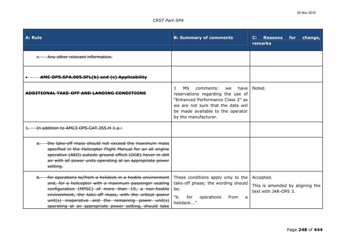
CRST Part-SPA
Page 248 of 444
A: Rule B: Summary of comments C: Reasons for change,
remarks
r. Any other relevant information.
AMC OPS.SPA.005.SFL(b) and (c) Applicability
ADDITIONAL TAKE-OFF AND LANDING CONDITIONS 1 MS comments: we have
reservations regarding the use of
“Enhanced Performance Class 2” as
we are not sure that the data will
be made available to the operator
by the manufacturer.
Noted.
1. In addition to AMC3 OPS.CAT.355.H 1.a.:
a. the take-off mass should not exceed the maximum mass
specified in the Helicopter Flight Manual for an all engine
operative (AEO) outside ground effect (OGE) hover in still
air with all power units operating at an appropriate power
setting.
b. for operations to/from a helideck in a hostile environment
and, for a helicopter with a maximum passenger seating
configuration (MPSC) of more than 19, a non-hostile
environment, the take-off mass, with the critical power
unit(s) inoperative and the remaining power unit(s)
operating at an appropriate power setting, should take
These conditions apply only to the
take-off phase; the wording should
be:
"b. for operations from a
helideck..."
Accepted.
This is amended by aligning the
text with JAR-OPS 3.
25 Nov 2010
CRST Part-SPA
Page 249 of 444
A: Rule B: Summary of comments C: Reasons for change,
remarks
into account:
Proposal: In order to restore the
original JAR-OPS 3 text (JAR-OPS
3.520 (a)(3)(ii) for take-off; JAR-
OPS 3.535(a)(3)(ii) for landing),
Eurocopter propose wording
modifications.
[modifications not repeated]
In JAR-OPS 3.520 (a)(3)(ii) and
JAR-OPS 3.535(a)(3)(ii), the
additional requirements (so-called
'Enhanced PC2') are applicable
either to helicopters located in a
hostile environment whatever the
MPSC is (condition B) or to
helicopters with an MPSC of more
than 19 (condition A).
Accepted.
This is rectified by aligning the
text with JAR-OPS 3.
i. the procedure used;
ii. deck-edge miss; and
iii. drop down appropriate to the height of the helideck.
25 Nov 2010

CRST Part-SPA
Page 250 of 444
A: Rule B: Summary of comments C: Reasons for change,
remarks
2. In addition to AMC3 OPS.CAT.355.H 4.a.:
a. the landing mass should not exceed the maximum mass
specified in the Helicopter Flight Manual for an all engine
operative (AEO) outside ground effect (OGE) hover in still
air with all power units operating at an appropriate power
setting.
b. for operations to/from a helideck in a hostile environment
and, for a helicopter with a MPSC of more than 19, a non-
hostile environment, the landing mass, with the critical
power unit(s) inoperative and the remaining power unit(s)
operating at an appropriate power setting, should take
into account:
These conditions apply only to the
landing phase; the wording should
be:
"b. for operations to a helideck..."
Accepted.
This is amended by aligning the
text with JAR-OPS 3.
i. the procedure used; and
ii. drop down appropriate to the height of the helideck.
GM1 OPS.SPA.005.SFL(b) Applicability
PROCEDURE FOR CONTINUED OPERATIONS TO HELIDECKS
25 Nov 2010

CRST Part-SPA
Page 251 of 444
A: Rule B: Summary of comments C: Reasons for change,
remarks
1. Factors to be considered when taking off from or landing on a
helideck
In order to take account of the considerable number of variables
associated with the helideck environment, each take-off and landing
may require a slightly different profile. Factors such as helicopter
mass and centre of gravity, wind velocity, turbulence, deck size,
deck elevation and orientation, obstructions, power margins,
platform gas turbine exhaust plumes etc., will influence both the
take-off and landing. In particular, for the landing, additional
considerations such as the need for a clear go-around flight path,
visibility and cloud base etc., will affect the pilot-in command‟s
decision on the choice of landing profile. Profiles may be modified,
taking account of the relevant factors noted above and the
characteristics of individual helicopter types.
2. Performance
To perform the following take-off and landing profiles, adequate all
engines operating (AEO) hover performance at the helideck is
required. In order to provide a minimum level of performance, data
(derived from the Flight Manual AEO out of ground effect (OGE), with
wind accountability) should be used to provide the maximum take-
off or landing mass. Where a helideck is affected by downdrafts or
turbulence or hot gases, or where the take-off or landing profile is
obstructed, or the approach or take-off cannot be made into wind, it
may be necessary to decrease this take-off or landing mass by using
25 Nov 2010

CRST Part-SPA
Page 252 of 444
A: Rule B: Summary of comments C: Reasons for change,
remarks
a suitable calculation method recommended by the manufacturer or
established by the operator. The helicopter mass should not exceed
that stated in AMC3 OPS.CAT.355.H 1.a. and 4.a.
3. Take-off profile
a. The take-off should be performed in a dynamic manner
ensuring that the helicopter continuously moves vertically
from the hover to the Rotation Point (RP) and thence into
forward flight. If the manoeuvre is too dynamic then there
is an increased risk of losing spatial awareness (through
loss of visual cues) in the event of a rejected take-off,
particularly at night.
b. If the transition to forward flight is too slow, the helicopter
is exposed to an increased risk of contacting the deck
edge in the event of an engine failure at or just after the
point of cyclic input (RP).
c. It has been found that the climb to RP is best made
between 110 % and 120 % of the power required in the
hover. This power offers a rate of climb which assists with
deck-edge clearance following power unit failure at RP,
whilst minimising ballooning following a failure before RP.
Individual types will require selection of different values
within this range.
25 Nov 2010

CRST Part-SPA
Page 253 of 444
A: Rule B: Summary of comments C: Reasons for change,
remarks
4. Selection of a lateral visual cue
In order to obtain the maximum performance in the event of an
engine failure being recognised at or just after RP, the RP must be at
its optimum value, consistent with maintaining the necessary visual
cues. If an engine failure is recognised just before RP, the helicopter,
if operating at a low mass, may „balloon‟ a significant height before
the reject action has any effect. It is, therefore, important that the
Pilot Flying selects a lateral visual marker and maintains it until the
RP is achieved, particularly on decks with few visual cues. In the
event of a rejected take-off, the lateral marker will be a vital visual
cue in assisting the pilot to carry out a successful landing.
5. Selection of the rotation point
25 Nov 2010

CRST Part-SPA
Page 254 of 444
A: Rule B: Summary of comments C: Reasons for change,
remarks
a. The optimum RP should be selected to ensure that the
take-off path will continue upwards and away from the
deck with All Engines Operating (AEO), but minimising the
possibility of hitting the deck edge due to the height loss
in the event of an engine failure at or just after RP.
b. The optimum RP may vary from type to type. Lowering
the RP will result in a reduced deck edge clearance in the
event of an engine failure being recognised at or just after
RP. Raising the RP will result in possible loss of visual
cues, or a hard landing in the event of an engine failure
just prior to RP.
6. Pilot reaction times
Pilot reaction time is an important factor affecting deck edge
clearance in the event of an engine failure prior to or at RP.
Simulation has shown that a delay of one second can result in a loss
of up to 15 ft in deck edge clearance.
7. Variation of wind speed
Relative wind is an important parameter in the achieved take-off
path following an engine failure; wherever practicable, take-off
should be made into wind. Simulation has shown that a 10 knot wind
can give an extra 5 ft deck edge clearance compared to a zero wind
It is not correct to write that 10 kt
wind increases by 5 ft the deck
edge clearance. This result is
depending on the helicopter type.
Not accepted .
It is correctly stated that
simulation has shown this effect.
With wind of less than 10 kt, the
25 Nov 2010

CRST Part-SPA
Page 255 of 444
A: Rule B: Summary of comments C: Reasons for change,
remarks
condition. There are even cases where the
wind will reduce the deck-edge
margin.
wind does not have the same
predictability.
However, it is expected that
manufacturers will produce their
own data to establish deck-edge
clearance.
8. Position of the helicopter relative to the deck edge
a. It is important to position the helicopter as close to the
deck edge (including safety nets) as possible whilst
maintaining sufficient visual cues, particularly a lateral
marker.
b. The ideal position is normally achieved when the rotor tips
are positioned at the forward deck edge. This position
minimises the risk of striking the deck edge following
recognition of an engine failure at or just after RP. Any
take-off heading which causes the helicopter to fly over
obstructions below and beyond the deck edge should be
avoided if possible. Therefore, the final take-off heading
and position will be a compromise between the take-off
path for least obstructions, relative wind, turbulence and
lateral marker cue considerations.
9. Actions in the event of an engine failure at or just after RP
25 Nov 2010

CRST Part-SPA
Page 256 of 444
A: Rule B: Summary of comments C: Reasons for change,
remarks
Once committed to the continued take-off, it is important, in the
event of an engine failure, to rotate the aircraft to the optimum
attitude in order to give the best chance of missing the deck edge.
The optimum pitch rates and absolute pitch attitudes should be
detailed in the profile for the specific type.
10. Take-off from helidecks which have significant movement
a. This technique should be used when the helideck
movement and any other factors, e.g. insufficient visual
cues, makes a successful rejected take-off unlikely.
Weight should be reduced to permit an improved one
engine inoperative capability, as necessary.
b. The optimum take-off moment is when the helideck is
level and at its highest point, e.g. horizontal on top of the
swell. Collective pitch should be applied positively and
sufficiently to make an immediate transition to climbing
forward flight. Because of the lack of a hover, the take-off
profile should be planned and briefed prior to lift off from
the deck.
11. Standard landing profile
The approach should be commenced into wind to a point outboard of
the helideck. Rotor tip clearance from the helideck edge should be
25 Nov 2010

CRST Part-SPA
Page 257 of 444
A: Rule B: Summary of comments C: Reasons for change,
remarks
maintained until the aircraft approaches this position at the requisite
height (type dependent) with approximately 10 knots ground-speed
and a minimal rate of descent. The aircraft is then flown on a flight
path to pass over the deck edge and into a hover over the safe
landing area.
12. Offset landing profile
If the normal landing profile is impracticable due to obstructions and
the prevailing wind velocity, the offset procedure may be used. This
should involve flying to a hover position, approximately 90° offset
from the landing point, at the appropriate height and maintaining
rotor tip clearance from the deck edge. The helicopter should then be
25 Nov 2010

CRST Part-SPA
Page 258 of 444
A: Rule B: Summary of comments C: Reasons for change,
remarks
flown slowly but positively sideways and down to position in a low
hover over the landing point. Normally, CP will be the point at which
helicopter begins to transition over the helideck edge.
13. Training
These techniques should be covered in the training required by Part-
OR.
GM2 OPS.SPA.005.SFL(b) Applicability
OPERATIONS TO/FROM ELEVATED FATO‟S OR HELIDECKS
1. This GM describes types of operation to/from helidecks and
elevated FATO‟s by helicopters operating in performance class
2, without an assured safe forced landing capability in the case
of take-off and landing. Exposure time is used, where the
probability of a power unit failure is regarded as extremely
remote, but if a power unit failure (engine failure) occurs during
the exposure time a safe force landing may not be possible.
2. Take Off - Non-Hostile Environment
a. Figure 1 shows a typical take-off profile for performance
class 2 operations from a helideck or an elevated FATO in
25 Nov 2010

CRST Part-SPA
Page 259 of 444
A: Rule B: Summary of comments C: Reasons for change,
remarks
a non-hostile environment (with exposure time).
b. If an engine failure occurs after the exposure time and
before DPATO, compliance with AMC OPS.SPA.005.SFL(b)
and (c) 1. will enable a safe force landing on the surface.
c. At or after the DPATO, the OEI flight path should clear all
obstacles by the margins specified in AMC3
OPS.CAT.H.355 2.
Note: An engine failure outside of exposure time should result in a
safe-forced-landing or safe continuation of the flight.
25 Nov 2010
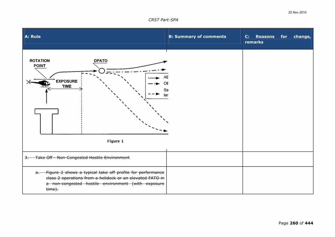
CRST Part-SPA
Page 260 of 444
A: Rule B: Summary of comments C: Reasons for change,
remarks
3. Take Off - Non-Congested Hostile Environment
a. Figure 2 shows a typical take off profile for performance
class 2 operations from a helideck or an elevated FATO in
a non-congested hostile environment (with exposure
time).
25 Nov 2010

CRST Part-SPA
Page 261 of 444
A: Rule B: Summary of comments C: Reasons for change,
remarks
b. If an engine failure occurs after the exposure time the
helicopter is capable of continuing the flight.
c. At or after the defined point after take-off (DPATO), the
OEI flight path should clear all obstacles by the margins
specified in AMC3 OPS.CAT.H.355 2.
Note: an engine failure outside of exposure time should result in a
safe-forced-landing or safe continuation of the flight.
25 Nov 2010
CRST Part-SPA
Page 262 of 444
A: Rule B: Summary of comments C: Reasons for change,
remarks
4. Landing - Non-Hostile Environment
a. Figure 3 shows a typical landing profile for performance
class 2 operations to a helideck or an elevated FATO in a
non-hostile environment (with exposure time).
b. The DPBL is defined as a “window” in terms of airspeed,
rate of descent, and height above the landing surface. If
an engine failure occurs before the DPBL, the pilot may
elect to land or to execute a balked landing.
c. In the event of an engine failure being recognised before
the exposure time compliance with AMC
OPS.SPA.005.SFL(b) and (c) 2. will enable a safe force
landing on the surface.
d. In the event of an engine failure after the exposure time,
compliance with AMC AMC OPS.SPA.005.SFL(b) and (c) 2.
will enable a safe force landing on the deck.
25 Nov 2010

CRST Part-SPA
Page 263 of 444
A: Rule B: Summary of comments C: Reasons for change,
remarks
5. Landing - Non-Congested Hostile
a. Figure 4 shows a typical landing profile for Performance
Class 2 operations to a helideck or an elevated FATO in a
non-congested hostile environment (with exposure time).
b. In the event of an engine failure at any point during the
approach and landing phase up to the start of exposure
25 Nov 2010
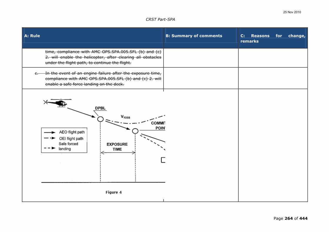
CRST Part-SPA
Page 264 of 444
A: Rule B: Summary of comments C: Reasons for change,
remarks
time, compliance with AMC OPS.SPA.005.SFL (b) and (c)
2. will enable the helicopter, after clearing all obstacles
under the flight path, to continue the flight.
c. In the event of an engine failure after the exposure time,
compliance with AMC OPS.SPA.005.SFL (b) and (c) 2. will
enable a safe force landing on the deck.
25 Nov 2010

CRST Part-SPA
Page 265 of 444
A: Rule B: Summary of comments C: Reasons for change,
remarks
GM OPS.SPA.005.SFL(c) Applicability
PERFORMANCE CLASS 2 - THE TAKE-OFF AND LANDING
PHASE
1. BENEFITS OF PERFORMANCE CLASS 2 WITH EXPOSURE
Following a Risk Assessment when the use of exposure is approved
the benefits are:
a. ability to operate when a safe-forced landing is not
assured in the take-off phase;
b. ability to penetrate the HV curve for short periods during
take-off or landing.
Risk Assessment used for fulfilment of this proposed standard should
be consistent with principles described in „AS/NZS 4360:1999‟.
1 MS comments: amend text to
include relevant text from the
quoted reference document.
Noted.
This is a large international
tract; as with ICAO references it
is best provided as a reference
rather than to include extracts.
Note: Terms used in this text and defined in the AS/NZS Standard
are shown in Sentence Case e.g. Risk Assessment or Risk
Reduction.
25 Nov 2010

CRST Part-SPA
Page 266 of 444
A: Rule B: Summary of comments C: Reasons for change,
remarks
2. OPERATIONS IN PERFORMANCE CLASS 2 WITH EXPOSURE
OPS.SPA.005.SFL (c) offers an opportunity to discount the
requirement for an assured safe-forced-landing area in the take-off
or landing phase - subject to an approval.
2.1 Limit of Exposure
As stated in GM3 OPS.CAT.H.355, performance class 2 has to ensure
AEO obstacle clearance to DPATO and OEI obstacle clearance from
that point. This does not change with the application of exposure.
It can therefore be stated that operations with exposure are
concerned only with alleviation from the requirement for the
provision of a safe-forced-landing.
The absolute limit of exposure is 200 ft - from which point OEI
obstacle clearance should be shown.
1 IND comments that it can never
be certain that exposure will end at
200 ft. They indicate that it is not
possible to „patch‟ into a CAT A
procedure after taking off with
exposure.
Noted.
Whilst it is correct that 200 ft
was an arbitrary line, it was
chosen because this represented
the start of the second segment
climb; for that reason, the
conversion from PC2 with
exposure to PC1 was only a
matter of being in a condition of
VY and clear of obstacles. If as
25 Nov 2010

CRST Part-SPA
Page 267 of 444
A: Rule B: Summary of comments C: Reasons for change,
remarks
suspected, the take-off is taken
up a valley into wind, then the
aircraft should be manoeuvred
to an into wind position before
200 ft above the landing site.
How is left to the pilot.
The text is copied from section 7
of ACJ to Subpart H and was
therefore already contained in
JAR-OPS 3.
2.2 The principle of Risk Assessment
ICAO Annex 6 Part III Chapter 3.1.2 (Sixth Edition July 2007) states:
“3.1.2 In conditions where the safe continuation of flight is not
ensured in the event of a critical power unit failure, helicopter
operations shall be conducted in a manner that gives appropriate
consideration for achieving a safe-forced-landing.”
Although a safe-forced-landing may no longer be the (absolute)
Standard, it is considered that Risk Assessment is obligatory to
satisfy the requirement for „appropriate consideration‟.
2.3 The application of Risk Assessment to Performance Class 2
25 Nov 2010

CRST Part-SPA
Page 268 of 444
A: Rule B: Summary of comments C: Reasons for change,
remarks
Under circumstances where no risk attributable to engine failure
(beyond that inherent in the safe-forced-landing) is present,
operations in performance class 2 may be conducted in accordance
with GM3 OPS.CAT.H.355 - and a safe-forced-landing will be
possible.
Under circumstances where such risk would be present i.e.:
operations to an elevated FATO (deck edge strike); or, when
permitted, operations from a site where a safe-forced-landing cannot
be accomplished because the surface is inadequate; or where there
is penetration into the Height Velocity (HV) curve for a short period
during take-off or landing (a limitation in CS 29 HFM‟s), operations
have to be conducted under a specific approval.
Provided such operations are Risk Assessed and can be conducted to
an established safety target - they may be approved.
2.3.1 The elements of the Risk Management
The approval process consists of an operational Risk Assessment and
the application of four principles:
a. a safety target;
b. a helicopter reliability assessment;
25 Nov 2010

CRST Part-SPA
Page 269 of 444
A: Rule B: Summary of comments C: Reasons for change,
remarks
c. continuing airworthiness; and
d. mitigating procedures.
2.3.2 The safety target
The main element of the Risk Assessment when exposure was
initially introduced into JAR-OPS 3 (NPA OPS-8), was the assumption
that turbine engines in helicopters would have failure rates of about
1:100 000 per flying hour; which would permit (against the agreed
safety target of 5 x 10⁻⁸ per event) an exposure of about 9 seconds
for twins during the take-off or landing event. (When choosing this
target it was assumed that the majority of current well maintained
turbine powered helicopters would be capable of meeting the event
target - it therefore represents the Residual Risk.)
Note: Residual Risk is considered to be the risk that remains when
all mitigating procedures - airworthiness and operational - are
applied (see sections 2.3.4 and 2.3.5 below).
2.3.3 The reliability assessment
The reliability assessment was initiated to test the hypothesis (stated
in 2.3.2 above) that the majority of turbine powered types would be
able to meet the safety target. This hypothesis could only be
25 Nov 2010

CRST Part-SPA
Page 270 of 444
A: Rule B: Summary of comments C: Reasons for change,
remarks
confirmed by an examination of the manufacturers‟ power-loss data.
2.3.4 Mitigating procedures (airworthiness)
Mitigating procedures consist of a number of elements:
a. the fulfilment of all manufacturers‟ safety modifications;
b. a comprehensive reporting system (both failures and
usage data); and
c. the implementation of a Usage Monitoring System (UMS).
Each of these elements is to ensure that engines, once shown to be
sufficiently reliable to meet the safety target, will sustain such
reliability (or improve upon it).
The monitoring system is felt to be particularly important as it had
already been demonstrated that when such systems are in place it
inculcates a more considered approach to operations. In addition the
elimination of „hot starts‟, prevented by the UMS, itself minimises the
incidents of turbine burst failures.
25 Nov 2010

CRST Part-SPA
Page 271 of 444
A: Rule B: Summary of comments C: Reasons for change,
remarks
2.3.5 Mitigating procedures (operations)
Operational and training procedures, to mitigate the risk - or
minimise the consequences - are required of the operator. Such
procedures are intended to minimise risk by ensuring that: the
helicopter is operated within the exposed region for the minimum
time; and simple but effective procedures are followed to minimise
the consequence should an engine failure occur.
2.4 Operation with Exposure - the alleviation and the requirement
When operating with exposure, there is alleviation from the
requirement to establish a safe-forced-landing area (which extends
to landing as well as take-off); however, the requirement for
obstacle clearance - AEO in the take-off and from DPATO OEI in the
climb and en-route phases - remains (both for take-off and landing).
The take-off mass is obtained from the more limiting of the
following:
a. the climb performance of 150 ft/min at 1000 ft above the
take-off point; or
b. obstacle clearance (in accordance with GM3
OPS.CAT.H.355 6.5); or
25 Nov 2010

CRST Part-SPA
Page 272 of 444
A: Rule B: Summary of comments C: Reasons for change,
remarks
c. AEO hover out of ground effect (HOGE) performance at
the appropriate power setting. (AEO HOGE is required to
ensure acceleration when (near) vertical dynamic take-off
techniques are being used. Additionally for elevated
FATO‟s/helidecks, it ensures a power reserve to offset
ground cushion dissipation; and ensures that, during the
landing manoeuvre, a stabilised HOGE is available -
should it be required.)
2.4.1 Operations to elevated FATO or helideck
Performance class 2 operations to elevated FATO or helideck are a
specific case of operations with exposure. In these operations, the
alleviation covers the possibility of:
a. a deck-edge strike if the engine fails early in the take-off
or late in the landing; and
b. penetration into the HV Curve during take-off and landing;
and
c. forced landing with obstacles on the surface (hostile water
conditions) below the elevated FATO (helideck). The take-
of mass is as stated above and relevant techniques are as
described in AMC OPS.SPA.005.SFL(b).
25 Nov 2010

CRST Part-SPA
Page 273 of 444
A: Rule B: Summary of comments C: Reasons for change,
remarks
Note: It is unlikely that the DPATO will have to be calculated with
operations to helidecks (due to the absence of obstacles in the
take-off path).
2.4.2 Additional requirements for operations to Helidecks in a Hostile
Environment
For a number of reasons (e.g. the deck size, and the helideck
environment – including obstacles and wind vectors), it is not
anticipated that operations in performance class 1 would be
technically feasible or economically justifiable (OEI HOGE could have
provided a method of compliance but this would have resulted in a
severe and unwarranted restriction on payload/range).
However, due to the severe consequences of an engine failure to
helicopters involved in take-off and landings to helidecks located in
hostile sea areas (such as the North Sea or the North Atlantic), a
policy of Risk Reduction is called for. As a result, enhanced
performance class 2 take-off and landing masses together with
techniques that provide a high confidence of safety due to: deck-
edge avoidance; and, drop-down that provides continued flight clear
of the sea, are seen as practical measures.
For helicopters which have a Category A elevated helideck
procedure, certification is satisfied by demonstrating a procedure and
adjusted masses (adjusted for wind as well as temperature and
pressure) which assure a 15 ft deck edge clearance on take-off and
landing. It is therefore recommended that manufacturers, when
25 Nov 2010

CRST Part-SPA
Page 274 of 444
A: Rule B: Summary of comments C: Reasons for change,
remarks
providing enhanced performance class 2 procedures, use the
provision of this deck-edge clearance as their benchmark.
As the height of the helideck above the sea is a variable, drop down
has to be calculated; once clear of the helideck, a helicopter
operating in performance class 1 would be expected to meet the 35
ft obstacle clearance. Under circumstances other than open sea
areas and with less complex environmental conditions, this would
not present difficulties. As the provision of drop down takes no
account of operational circumstances, standard drop down graphs for
enhanced performance class 2 - similar to those in existence for
Category A procedures - are anticipated.
Under conditions of offshore operations, calculation of drop down is
not a trivial matter - the following examples indicate some of the
problems which might be encountered in hostile environments:
a. Occasions when tide is not taken into account and the sea
is running irregularly - the level of the obstacle (i.e. - the
sea) is indefinable making a true calculation of drop down
impossible.
b. Occasions when it would not be possible - for operational
reasons - for the approach and departure paths to be
clear of obstacles - the „standard‟ calculation of drop-down
could not be applied.
25 Nov 2010

CRST Part-SPA
Page 275 of 444
A: Rule B: Summary of comments C: Reasons for change,
remarks
Under these circumstances, practicality indicates that drop-down
should be based upon the height of the deck AMSL and the 35 ft
clearance should be applied.
There are however, other and more complex issues which will also
affect the deck-edge clearance and drop down calculations:
c. When operating to moving decks on vessels, a
recommended landing or take-off profile might not be
possible because the helicopter might have to hover
alongside in order that the rise and fall of the ship is
mentally mapped; or, on take-off re-landing in the case of
an engine failure might not be an option.
Under these circumstances, the pilot-in-command might adjust the
profiles to address a hazard more serious or more likely than that
presented by an engine failure.
It is because of these and other (unforeseen) circumstances that a
prescriptive requirement is not used. However, the target remains a
15 ft deck-edge clearance and a 35ft obstacle clearance and data
should be provided such that, where practically possible, these
clearances can be planned.
As accident/incident history indicates that the main hazard is
collision with obstacles on the helideck due to human error, simple
and reproducible take-off and landing procedures are recommended.
25 Nov 2010

CRST Part-SPA
Page 276 of 444
A: Rule B: Summary of comments C: Reasons for change,
remarks
In view of the reasons stated above, the future requirement for
performance class 1 was replaced by the new requirement that the
take-off mass takes into account: the procedure; deck-edge miss;
and drop down appropriate to the height of the helideck. This will
require calculation of take-off mass from information produced by
manufacturers reflecting these elements. It is expected that such
information will be produced by performance modelling/simulation
using a model validated through limited flight testing.
2.4.3 Operations to helidecks for helicopters with a MPSC of more
than 19
The original requirement for operations of helicopters with a MPSC of
more than 19 was performance class 1 (as set out in OPS.CAT.355.H
(a)(2)).
However, when operating to helidecks, the problems enumerated in
2.4.2 above are equally applicable to these helicopters. In view of
this, but taking into account that increased numbers are (potentially)
being carried, such operations may be permitted in enhanced
performance class 2 (OPS.CAT.355.H (a)(3)) but, in all helideck
environments (both hostile and non-hostile), have to satisfy, the
additional requirements, set out in 2.4.2 above.
GM OPS.SPA.005.SFL(d) Applicability
25 Nov 2010

CRST Part-SPA
Page 277 of 444
A: Rule B: Summary of comments C: Reasons for change,
remarks
PERFORMANCE CLASS 3 - THE TAKE-OFF AND LANDING
PHASE
1 MS comments:
There are several places in the text
where the original text of “VY or
200 ft” has been replaced with
“200 ft”.
Accepted.
Restoration of the original text
rectifies the problem.
1. To understand the use of ground level exposure in performance
class 3, it is important first to be aware of the logic behind the
use of „take-off and landing phases‟; once this is clear, it is
easier to appreciate the aspects and limits of the use of ground
level exposure. This GM shows the derivation of the term from
the ICAO definition of the „en-route phase‟ and then gives
practical examples of the use, and limitations on the use, of
ground level exposure in OPS.SPA.005.SFL (d).
2. The take-off phase in performance class 1 and 2 may be
considered to be bounded by „the specified point in the take-off‟
from which the take-off flight path begins.
a. In performance class 1 this specified point is defined as
“the end of the take-off distance required”.
b. In performance class 2 this specified point is defined as
“DPATO or, as an alternative, no later than 200 ft above
the take-off surface”.
25 Nov 2010
CRST Part-SPA
Page 278 of 444
A: Rule B: Summary of comments C: Reasons for change,
remarks
c. There is no simple equivalent point for bounding of the
landing in performance class 1 and 2.
3. Take-off flight path is not used in performance class 3 and,
consequently, the term „take-off and landing phases‟ is used to
bound the limit of exposure. For the purpose of performance
class 3, the take-off and landing phases are considered to be
bounded by:
a. for the take-off no later than 200 ft above the take-off
surface; and
b. for the landing 200 ft above the landing surface.
Note: in ICAO Annex 6 Part III, En-route phase is defined as being
“That part of the flight from the end of the take-off and initial
climb phase to the commencement of the approach and landing
phase.” The use of take-off and landing phase in this text is
used to distinguish the take-off from the initial climb, and the
landing from the approach: they are considered to be
complimentary and not contradictory.
4. Ground level exposure – and exposure for elevated FATO‟s or
helidecks in a non-hostile environment – is permitted for
operations under an approval in accordance with section
OPS.SPA.SFL. Exposure in this case is limited to the „take-off
and landing phases‟.
25 Nov 2010

CRST Part-SPA
Page 279 of 444
A: Rule B: Summary of comments C: Reasons for change,
remarks
What is the practical effect of this bounding of exposure? Consider a
couple of examples:
a. A clearing: an operator may consider a take-off/landing in
a clearing when there is sufficient power, with all engines
operating, to clear all obstacles in the take-off path by an
adequate margin (this, in ICAO, is meant to indicate 35
ft). Thus, the clearing may be bounded by bushes, fences,
wires and, in the extreme, by power lines, high trees etc.
Once the obstacle has been cleared – by using a steep or
a vertical climb (which itself may infringe the HV diagram)
- the helicopter reaches 200 ft, and from that point a safe
forced landing must be possible. The effect is that whilst
operation to a clearing is possible, operation to a clearing
in the middle of a forest is not (except when operated in
accordance with OPS.SPA.005.SFL (d)(3)).
b. An aerodrome surrounded by rocks: the same applies
when operating to a landing site that is surrounded by
rocky ground. Once 200 ft has been reached, a safe
forced landing must be possible.
c. An elevated FATO or helideck: when operating to an
elevated FATO or helideck in Performance Class 3,
exposure is considered to be twofold: firstly, to a deck-
edge strike if the engine fails after the decision to
transition has been taken; and secondly, to operations in
the HV diagram due to the height of the elevated FATO or
25 Nov 2010

CRST Part-SPA
Page 280 of 444
A: Rule B: Summary of comments C: Reasons for change,
remarks
helideck. Once the take-off surface has been cleared and
the helicopter has reached the knee of the HV diagram,
the helicopter should be capable of making a safe forced
landing.
5. Operation in accordance with OPS.SPA.005.SFL (d) does not
permit excursions into a hostile environment such as and is
specifically concerned with the absence of space to abort the
take-off or landing when the take-off and landing space are
limited; or when operating in the HV diagram.
The original text 'per se' has been
translated as 'such as' instead of
retaining the original, or using the
more correct 'as such'.
Noted.
A return to the original text
removes this anomaly.
6. Specifically, the use of this exception to the requirement for a
safe forced landing (during take-off or landing) does not permit
semi-continuous operations over a hostile environment such as
a forest or hostile sea area. It can therefore be seen as a
limited alleviation from AMC4 OPS.CAT.355.H 1.a. which states
that: “operations are only conducted to/from those
aerodromes/operating sites and over such routes, areas and
diversions contained in a non-hostile environment…”.
The proposal is to remove this
paragraph and to introduce the MS
alleviation for 50 % or 5 minutes
en-route.
Not accepted.
The text reflects the JAR-OPS
text; any change/new principles
should be subject to a proposal
for a new Rulemaking task.
AMC OPS.SPA.005.SFL(e) Applicability
OPERATIONS AT A PUBLIC INTEREST SITE
The exemption specified in OPS.SPA.005.SFL (e) should only be
approved by the competent authority provided the helicopter mass
does not exceed the maximum mass specified in the Helicopter Flight
8 % -requirement
The requirement will be an issue at
Noted.
This has been a long standing
25 Nov 2010

CRST Part-SPA
Page 281 of 444
A: Rule B: Summary of comments C: Reasons for change,
remarks
Manual for a climb gradient of 8 % in still air; at the appropriate
take-off safety speed (VTOSS) with the critical power units operating
at an appropriate power rating.
higher altitudes and/or higher
temperatures. This leads to an
obligation to reduce mission
weight, e.g. fuel quantity.
Example (EC145)
To achieve the 8 % climb gradient
in respect of the fuel
requirement, the endurance will be
limited to 55 minutes in day
conditions and 42 minutes at night.
requirement of the PIS
Appendix..
GM1 OPS.SPA.005.SFL(e) Applicability
HELICOPTER MASS LIMITATIONS FOR OPERATIONS AT A
PUBLIC INTEREST SITE
It is not apparent where this data
comes from. JAR-OPS 3 and CS-29
CAT A does not address it.
Noted.
Flight manuals provide the data
to establish this climb gradient.
1. The helicopter mass limitation at take-off or landing specified in
AMC OPS.SPA.005.SFL (e) should be determined using the
climb performance data from 35 ft to 200 ft at VTOSS (First
segment of the take-off flight path) contained in the Category A
supplement of the Helicopter Flight Manual (or equivalent
manufacturer data acceptable to the EASA according to AMC
OPS.GEN.010(a)(9)&(10)).
25 Nov 2010

CRST Part-SPA
Page 282 of 444
A: Rule B: Summary of comments C: Reasons for change,
remarks
2. The first segment climb data to be considered is established for
a climb at the take-off safety speed VTOSS, with the landing gear
extended (when the landing gear is retractable), with the
critical power unit inoperative and the remaining power units
operating at an appropriate power rating (the 2 min 30 sec or 2
min One Engine Inoperative power rating, depending on the
helicopter type certification). The appropriate VTOSS, is the value
specified in the Category A performance section of the
Helicopter Flight Manual for vertical take-off and landing
procedures (VTOL or equivalent).
3. The ambient conditions at the aerodrome or operating site
(pressure-altitude and temperature) should be taken into
account.
4. The data is usually provided in charts one of the following
ways:
a. Height gain in ft over a horizontal distance of 100 ft in the
first segment configuration (35 ft to 200 ft, VTOSS, 2 min
30 sec / 2 min OEI power rating). This chart should be
entered with a height gain of 8 ft per 100 ft horizontally
travelled, resulting in a mass value for every pressure-
altitude/temperature combination considered.
b. Horizontal distance to climb from 35 ft to 200 ft in the first
segment configuration (VTOSS, 2 min 30 sec / 2 min OEI
power rating). This chart should be entered with a
25 Nov 2010

CRST Part-SPA
Page 283 of 444
A: Rule B: Summary of comments C: Reasons for change,
remarks
horizontally distance of 628 m (2 062 ft), resulting in a
mass value for every pressure-altitude/temperature
combination considered.
c. Rate of climb in the first segment configuration (35 ft to
200 ft, VTOSS, 2 min 30 sec / 2 min OEI power rating). This
chart can be entered with a rate of climb equal to the
climb speed (VTOSS) value in knots (converted to True
Airspeed) multiplied by 8.1, resulting in a mass value for
every pressure-altitude/temperature combination
considered.
GM2 OPS.SPA.005.SFL(d) Applicability
HELICOPTER OPERATIONS TO/FROM A PUBLIC INTEREST
SITE
1. General
Appendix 1 to JAR-OPS 3.005(i) - contained alleviations for public
interest sites - was introduced in January 2002 to address problems
that had been encountered by States at hospital (and lighthouse)
sites due to the applicable performance requirements of performance
class 1 and 2. These problems were enumerated in ACJ to Appendix
1 to JAR-OPS 3.005(d) paragraph 8, part of which is reproduced
25 Nov 2010

CRST Part-SPA
Page 284 of 444
A: Rule B: Summary of comments C: Reasons for change,
remarks
below.
“8 Problems with hospital sites
During implementation of JAR-OPS 3, it was established that a
number of States had encountered problems with the impact of
performance rules where helicopters were operated for HEMS.
Although States accept that progress should be made towards
operations where risks associated with a critical power unit failure
are eliminated, or limited by the exposure time concept, a number of
landing sites exist which do not (or never can) allow operations to
Performance Class 1 or 2 requirements.
These sites are generally found in a congested hostile environment:
- in the grounds of hospitals; or
- on hospital buildings.
The problem of hospital sites is mainly historical and, whilst the
authority could insist that such sites not be used - or used at such a
low weight that critical power unit failure performance is assured, it
would seriously curtail a number of existing operations.
25 Nov 2010

CRST Part-SPA
Page 285 of 444
A: Rule B: Summary of comments C: Reasons for change,
remarks
Even though the rule for the use of such sites in hospital grounds for
HEMS operations (Appendix 1 to JAR-OPS 3.005(d) sub-paragraph
(c)(2)(i)(A)) attracted alleviation until 2005, it was only partial and
will still impact upon present operations.
Because such operations are performed in the public interest, it was
felt that the authority should be able to exercise its discretion so as
to allow continued use of such sites provided that it is satisfied that
an adequate level of safety can be maintained - notwithstanding that
the site does not allow operations to Performance Class 1 or 2
standards. However, it is in the interest of continuing improvements
in safety that the alleviation of such operations be constrained to
existing sites, and for a limited period.”
As stated in that ACJ and embodied in the text of the appendix, the
solution was short term (until 31 December 2004). During the
comment period of NPA 18, representations were made to the JAA
that the alleviation should be extended to 2009. The review
committee, in not accepting this request, had in mind that this was a
short-term solution to address an immediate problem, and a
permanent solution should be sought.
2. Public Interest Sites after 1 January 2005
Although elimination of such sites would remove the problem, it is
recognized that phasing out, or rebuilding existing hospital and
lighthouses, is a long-term goal which may not be cost-effective, or
25 Nov 2010

CRST Part-SPA
Page 286 of 444
A: Rule B: Summary of comments C: Reasons for change,
remarks
even possible, in some Member States.
It should be noted, however, that existing paragraph (e)(3) of
OPS.SPA.005.SFL (which is transferred from JAR-OPS 3) limits the
problem by confining approvals to public interest sites established
before 1 July 2002 (established in this context means either: built
before that date; or brought into service before that date – this
precise wording was used to avoid problems associated with a
ground level where no building would be required). Thus, the
problem of these sites is contained and reducing in severity. This
date was set approximately 6 months after the intended
implementation of this original appendix.
EASA adopted the JAA philosophy that from 1st January 2005 the
approval of a public interest site would be confined to those sites
where a CAT A procedure alone cannot solve the problem. The
determination of whether the helicopter can or cannot be operated in
accordance performance class 1 criteria should be established with
the helicopter at a realistic payload and fuel to complete the mission.
However, in order to reduce the risk at those sites, AMC
OPS.SPA.005.SFL (e) should be applied.
Delete "CAT A" and add
”performance class 1”.
Not accepted.
The reference is appropriate.
Additionally and in order to promote understanding of the problem,
the text contained in paragraph (e) of the JAR-OPS 3 appendix had
been amended to refer to performance class 1 and not to Annex 14
as in the original appendix. Thus Part C of the Operations Manual
should reflect the non-conformance with that Subpart.
25 Nov 2010

CRST Part-SPA
Page 287 of 444
A: Rule B: Summary of comments C: Reasons for change,
remarks
The following paragraphs discuss the problem and solutions.
3. The problem associated with public interest sites
There are a number of problems: some of which can be solved with
the use of appropriate helicopters and procedures; and others which,
because of the size of the FATO or the obstacle environment, cannot.
They consist of:
a. Helicopters that could not meet the required performance
class 1;
b. The size of the FATO of the public interest site (smaller
than that required by the manufacturers‟ procedure);
c. An obstacle environment that prevents the use of the
manufacturers procedure (obstacles in the back-up area);
d. An obstacle environment that does not allow recovery
following a power unit failure in the critical phase of take-
off (a line of buildings requiring a demanding gradient of
climb) at a realistic payload and fuel to complete the
mission; or
25 Nov 2010

CRST Part-SPA
Page 288 of 444
A: Rule B: Summary of comments C: Reasons for change,
remarks
e. A ground level public interest site (exposure is not
permitted).
3.1 Problems associated with a; it was recognised at the time of
the adoption of the original appendix that, although the number
of helicopters not meeting the absolute performance criteria of
a. above were dwindling, existing HEMS and lighthouse fleets
could not be replaced until 2005. The limited alleviations should
at the time of implementation of the Community Implementing
Rules be non existent.
3.2 Problems associated with b.; the inability to climb and conduct
a rejected landing back to the public interest site following an
engine failure before the Decision Point (DP).
3.3 Problems associated with c.; as in b.
3.4 Problems associated with d; climb into an obstacle following an
engine failure after DP.
3.5 Problems associated with e.; may be related to:
a. the size of the FATO which is too small for the
manufacturers‟ procedure;
25 Nov 2010

CRST Part-SPA
Page 289 of 444
A: Rule B: Summary of comments C: Reasons for change,
remarks
b. no room for back-up;
c. an obstacle in the take-off path; or
d. a mixture of all three.
With the exception of case a., problems cannot be solved in the
immediate future but can, when mitigated with the use of the latest
generation of helicopters (operated at a weight that can allow useful
payloads and endurance), minimise exposure to risk.
4. Long Term Solution
Although not offering a complete solution, it was felt that a
significant increase in safety could be achieved by applying an
additional performance margin to such operations. This solution
could also be seen as mitigation proportional to the problem and
would allow the time restriction of 2004 to be removed.
The required performance level of 8 % climb gradient in the first
segment, reflects ICAO Annex 14 Volume II in Table 4-3 –
Dimensions and slopes of obstacle limitations surfaces for
performance class 2.
In 4 the second paragraph is a
general requirement made by
ICAO; HEMS operations should be
more demanding.
Not accepted.
ICAO currently requires 4.5 %
for operation with OEI; the 8 %
is a twin engine requirement
and, as such, represents a
substantial increase concomitant
25 Nov 2010

CRST Part-SPA
Page 290 of 444
A: Rule B: Summary of comments C: Reasons for change,
remarks
with the exposure.
The performance delta is achieved without the provision of further
manufacturer‟s data by using existing graphs to provide the Reduced
take-off mass (RTOM).
4.1 Solution with relation to b.; although the problem still exists,
the safest procedure is a dynamic take-off reducing the time taken
to achieve Vstayup and thus allowing Visual Flight Rules (VFR)
recovery – if the failure occurs at or after Vy and 200 feet, an
Instrument Flight Rules (IFR) recovery is possible.
4.2 Solution with relation to c.; as in b. above.
4.3 Solution with relation to d.; once again this does not give a
complete solution, however the performance delta minimise the time
during which a climb over the obstacle cannot be achieved.
4.4 Solution with relation to e.; as in 4.1 to 4.3 above.
GM3 OPS.SPA.005.SFL(e) Applicability
IMPROVEMENT PROGRAMME FOR PUBLIC INTEREST SITES
25 Nov 2010

CRST Part-SPA
Page 291 of 444
A: Rule B: Summary of comments C: Reasons for change,
remarks
1. General
Although it is accepted that there will be a number of public interest
sites that will remain for some time, it is in the interest of safety that
the numbers are reduced and eventually, as a goal, all sites
eliminated. A reduction of sites can be achieved in two ways:
a. By an improvement in the performance of helicopters such
that HOGE OEI (Hover out of ground effect one engine inoperative)
is possible at weights where the mission can be performed.
b. By the use of a site improvement programme: to take out of
service those sites where the exposure is greatest; or by improving
sites such that the performance requirement can be met.
2. Improvement in performance
The advent of more powerful modern twin-engine helicopters has put
into reach the ability to achieve the aim stated in 1.a. above. Today,
most of these helicopters are at the point where HOGE OEI with
mission payload is possible.
3. Improvement of Sites
Where a site could be improved by redevelopment, for example by
increasing the size of the FATO, it should be done; where the
25 Nov 2010

CRST Part-SPA
Page 292 of 444
A: Rule B: Summary of comments C: Reasons for change,
remarks
problems of a site are due to the obstacle environment, a
programme to re-site the facility or remove the obstacle(s) should be
undertaken as a priority.
4. Summary
As stated in paragraph 1. above, it is in the interest of States to
reduce the risk of an accident due to an engine failure on take-off or
landing. This could be achieved with a combination of policies:
a. the use of more appropriate helicopters;
b. improvement by redevelopment of a site; or
c. the re-siting of facilities to alternative locations.
The improvement policy should be achieved in a reasonable time
horizon – and this should be an element of the compliance program.
The approval to operate to public interest sites could be conditional
upon such improvement programs being put into place. Unless such
a policy is instituted, there will be no incentive for public interest
sites to be eliminated in a reasonable time horizon.
25 Nov 2010
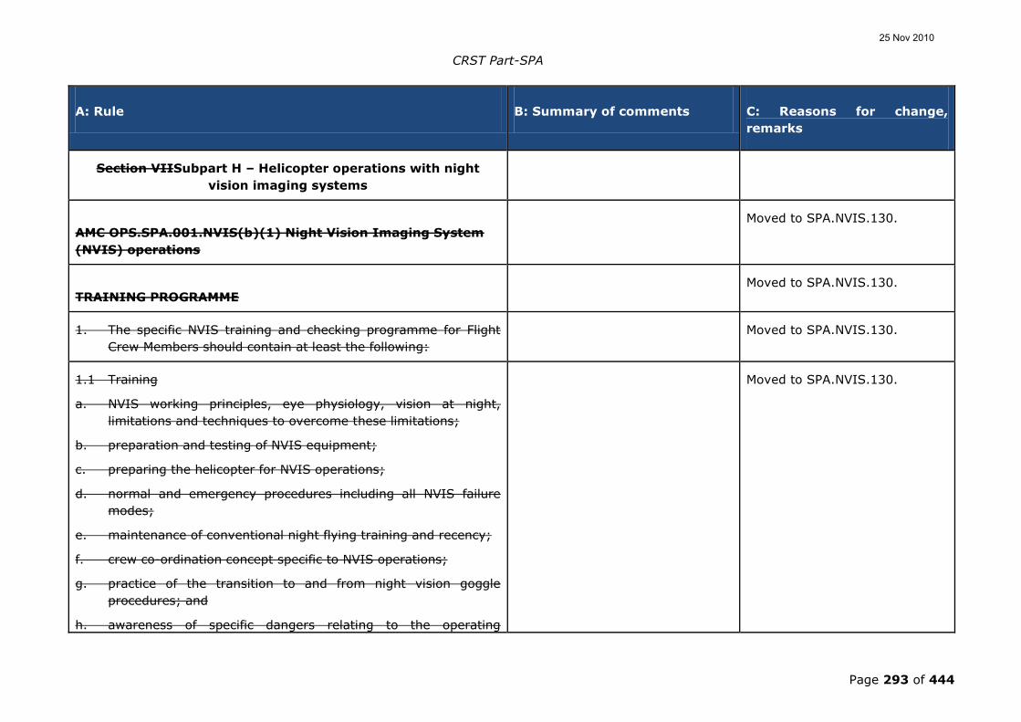
CRST Part-SPA
Page 293 of 444
A: Rule B: Summary of comments C: Reasons for change,
remarks
Section VIISubpart H – Helicopter operations with night
vision imaging systems
AMC OPS.SPA.001.NVIS(b)(1) Night Vision Imaging System
(NVIS) operations
Moved to SPA.NVIS.130.
TRAINING PROGRAMME Moved to SPA.NVIS.130.
1. The specific NVIS training and checking programme for Flight
Crew Members should contain at least the following:
Moved to SPA.NVIS.130.
1.1 Training
a. NVIS working principles, eye physiology, vision at night,
limitations and techniques to overcome these limitations;
b. preparation and testing of NVIS equipment;
c. preparing the helicopter for NVIS operations;
d. normal and emergency procedures including all NVIS failure
modes;
e. maintenance of conventional night flying training and recency;
f. crew co-ordination concept specific to NVIS operations;
g. practice of the transition to and from night vision goggle
procedures; and
h. awareness of specific dangers relating to the operating
Moved to SPA.NVIS.130.
25 Nov 2010

CRST Part-SPA
Page 294 of 444
A: Rule B: Summary of comments C: Reasons for change,
remarks
environment;
1.2 Checking: Moved to SPA.NVIS.130.
a. Night Proficiency Checks as appropriate including
emergency procedures to be used on NVIS operations.
Many comments request the
possibility to combine NVIS checks
with PPC or HHO checks. The
choice shall be left to the operator
as long as it is approved by the
national authority.
The comment was rejected.
There is no reason why
elements of these checks cannot
be aggregated – it was never
intended that there would be
separate checks for all different
types of operation. If night
operations are being conducted,
then it is likely that they will be
conducted with NVIS in place.
Moved to SPA.NVIS.130.
b. Line checks with special emphasis on the following:
i. local area meteorology;
ii. NVIS flight planning;
iii. NVIS in flight procedures;
iv. transitions to and from NVGs;
v. normal NVIS procedures; and
Moved to SPA.NVIS.130.
25 Nov 2010
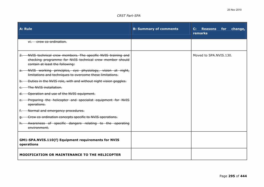
CRST Part-SPA
Page 295 of 444
A: Rule B: Summary of comments C: Reasons for change,
remarks
vi. crew co-ordination.
2. NVIS technical crew members. The specific NVIS training and
checking programme for NVIS technical crew member should
contain at least the following:
a. NVIS working principles, eye physiology, vision at night,
limitations and techniques to overcome these limitations.
b. Duties in the NVIS role, with and without night vision goggles.
c. The NVIS installation.
d. Operation and use of the NVIS equipment.
e. Preparing the helicopter and specialist equipment for NVIS
operations.
f. Normal and emergency procedures.
g. Crew co-ordination concepts specific to NVIS operations.
h. Awareness of specific dangers relating to the operating
environment.
Moved to SPA.NVIS.130.
GM1-SPA.NVIS.110(f) Equipment requirements for NVIS
operations
MODIFICATION OR MAINTENANCE TO THE HELICOPTER
25 Nov 2010

CRST Part-SPA
Page 296 of 444
A: Rule B: Summary of comments C: Reasons for change,
remarks
It is important that the operator reviews and considers all
modifications or maintenance to the helicopter with regard to
the NVIS airworthiness approval. Special emphasis needs to
be paid to modification and maintenance of equipment such
as light emitting or reflecting devices, transparencies and
avionics equipment, as the function of this equipment may
interfere with the NVGs.
GM1-SPA.NVIS.130 Crew requirements for NVIS operations
UNDERLYING ACTIVITY
Examples of an underlying activity are:
1. commercial air transport;
2. helicopter emergency medical service (HEMS); and
3. helicopter hoist operation (HHO).
GM1-SPA.NVIS.130(e)Crew requirements for NVIS operations
OPERATIONAL APPROVAL
When determining the composition of the minimum crew, the
competent authority should take account of the type of
operation that is to be conducted. The minimum crew should
25 Nov 2010
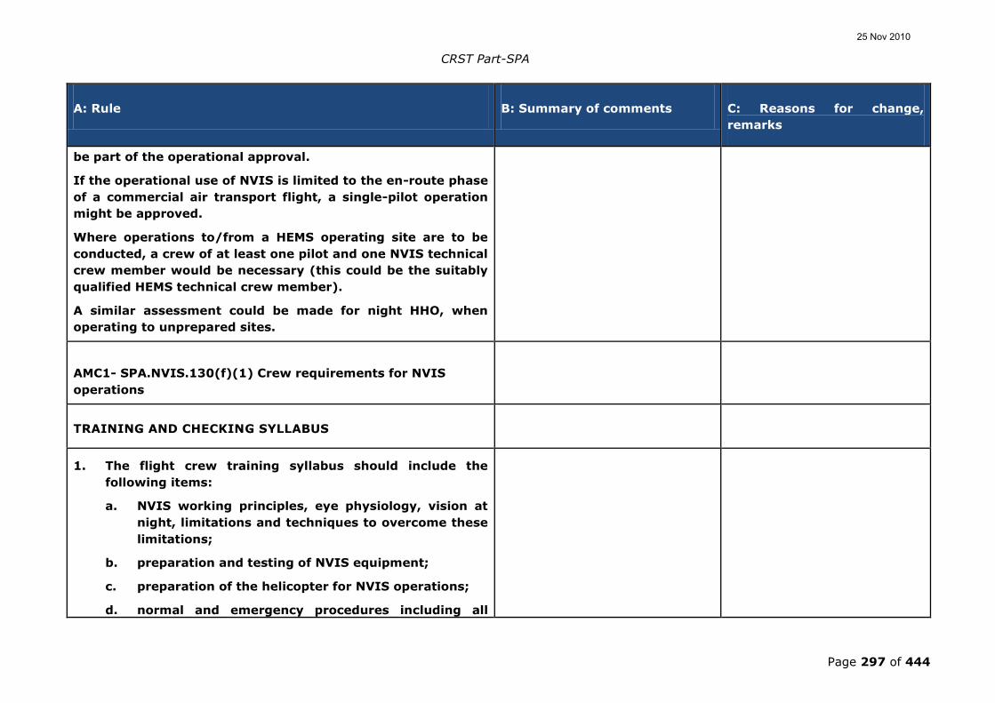
CRST Part-SPA
Page 297 of 444
A: Rule B: Summary of comments C: Reasons for change,
remarks
be part of the operational approval.
If the operational use of NVIS is limited to the en-route phase
of a commercial air transport flight, a single-pilot operation
might be approved.
Where operations to/from a HEMS operating site are to be
conducted, a crew of at least one pilot and one NVIS technical
crew member would be necessary (this could be the suitably
qualified HEMS technical crew member).
A similar assessment could be made for night HHO, when
operating to unprepared sites.
AMC1- SPA.NVIS.130(f)(1) Crew requirements for NVIS
operations
TRAINING AND CHECKING SYLLABUS
1. The flight crew training syllabus should include the
following items:
a. NVIS working principles, eye physiology, vision at
night, limitations and techniques to overcome these
limitations;
b. preparation and testing of NVIS equipment;
c. preparation of the helicopter for NVIS operations;
d. normal and emergency procedures including all
25 Nov 2010

CRST Part-SPA
Page 298 of 444
A: Rule B: Summary of comments C: Reasons for change,
remarks
NVIS failure modes;
e. maintenance of unaided night flying;
f. crew co-ordination concept specific to NVIS
operations;
g. practice of the transition to and from NVG
procedures;
h. awareness of specific dangers relating to the
operating environment; and
i. risk analysis, mitigation and management.
2. The flight crew checking syllabus should include:
a. night proficiency checks, including emergency
procedures to be used on NVIS operations; and
b. line checks with special emphasis on the following:
i. local area meteorology;
ii. NVIS flight planning;
iii. NVIS in-flight procedures;
iv. transitions to and from night vision goggles
(NVGs);
v. normal NVIS procedures; and
vi. crew coordination specific to NVIS operations.
3. Whenever the crew is required to also consist of an NVIS
technical crew member, he/she should be trained and
25 Nov 2010
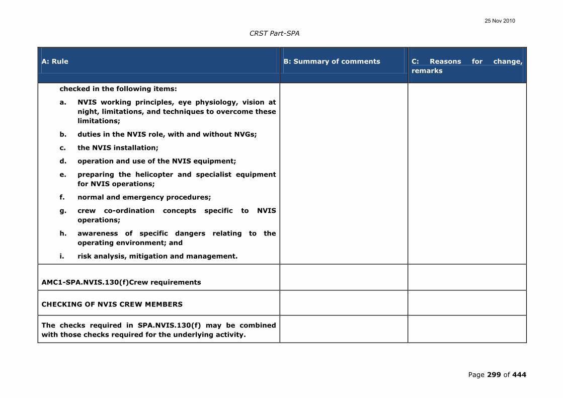
CRST Part-SPA
Page 299 of 444
A: Rule B: Summary of comments C: Reasons for change,
remarks
checked in the following items:
a. NVIS working principles, eye physiology, vision at
night, limitations, and techniques to overcome these
limitations;
b. duties in the NVIS role, with and without NVGs;
c. the NVIS installation;
d. operation and use of the NVIS equipment;
e. preparing the helicopter and specialist equipment
for NVIS operations;
f. normal and emergency procedures;
g. crew co-ordination concepts specific to NVIS
operations;
h. awareness of specific dangers relating to the
operating environment; and
i. risk analysis, mitigation and management.
AMC1-SPA.NVIS.130(f)Crew requirements
CHECKING OF NVIS CREW MEMBERS
The checks required in SPA.NVIS.130(f) may be combined
with those checks required for the underlying activity.
25 Nov 2010

CRST Part-SPA
Page 300 of 444
A: Rule B: Summary of comments C: Reasons for change,
remarks
GM1- OPS.SPA.NVIS.01301.NVIS(fb)(1)Crew
requirementsNight Vision Imaging System (NVIS) operations
TRAINING GUIDELINES AND CONSIDERATIONSPROGRAMME
1. PURPOSEPurpose
The purpose of this Guidance Material is to recommend the
minimum training guidelines and any associated considerations
necessary for the safe operation of a helicopter while operating
with night vision imaging systems (NVISs).
To provide an appropriate level of safety, training procedures
should accommodate the capabilities and limitations of the
NVIS and associated systems as well as the restraints of the
operational environment.
2. ASSUMPTIONSAssumptions
The following assumptions were used in the creation of this
documentmaterial:
2.1a. Most civilian operators may not have the benefit of formal
NVIS training, similar to that offered by the military.
Therefore, the stated considerations are predicated on
that individual who has no prior knowledge of NVIS or
how to use them in flight. The degree to which other
25 Nov 2010

CRST Part-SPA
Page 301 of 444
A: Rule B: Summary of comments C: Reasons for change,
remarks
applicants who have had previous formal training should
be exempted from this training will be
dependantdependent on their prior NVIS experience.
2.2b. While NVIS are principally an aid to visual flight
rules (VFR)_ night flight, the 2 dimensional nature of the
NVG image necessitates frequent reference to the flight
instruments for spatial and situational awareness
information. The reduction of peripheral vision and
increased reliance on focal vision exacerbates this
requirement to monitor flight instruments. Therefore, any
basic NVIS training syllabus should include some
instruction on basic instrument flight.
3. TWO TIERED APPROACH: BASIC & ADVANCED TRAININGTwo-
tiered approach: basic and advance training
To be effective, the NVIS training philosophy would be based on
a two-tiered approach: basic and advanced NVIS training. The
basic NVIS training would serve as the baseline standard for all
individuals seeking an NVIS endorsement. The content of this
initial training would not be dependent on any operational
requirements. The training required for any individual pilot
should take into account the previous NVIS flight experience.
The advanced training would build on the basic training by
focusing on developing specialized skills required to operate a
helicopter during NVIS operations in a particular operational
environment. Furthermore, while there is a need to stipulate
25 Nov 2010

CRST Part-SPA
Page 302 of 444
A: Rule B: Summary of comments C: Reasons for change,
remarks
minimum flight hour requirements for an NVIS endorsement,
the training should also be event based. This necessitates that
operators be exposed to all of the relevant aspects, or events,
of NVIS flight in addition to acquiring a minimum number of
flight hours. NVIS training should include flight in a variety of
actual ambient light and weather conditions.
4. TRAINING REQUIREMENTSTraining requirements One MS asks for a sentence saying
that the training should be done
during dark night. If a pilot is
trained during a very short period,
he could be trained during light
nights only, which is not acceptable
as it is not representative.
Not accepted. The Agency has a
definition of “night”.
Furthermore in GM
OPS.SPA.001.NVIS (b)(1)
subparagraph 3. It is stated that
NVIS training should include
flight in a variety of actual
ambient light and weather
conditions.
4.1a. Flight cCrew Gground Ttraining
The ground training necessary to initially qualify a pilot to
act as the pilot of a helicopter using night vision goggles
should include at least the following subjects:
4.1.1i. Applicable aviation regulations that relate to
NVIS limitations and flight operations.
25 Nov 2010

CRST Part-SPA
Page 303 of 444
A: Rule B: Summary of comments C: Reasons for change,
remarks
4.1.2ii. Aero- medical factors relating to the use of
NVGs to include how to protect night vision, how the
eyes adapt to operate at night, self -imposed stresses
that affect night vision, effects of lighting (internal
and external) on night vision, cues utilized to
estimate distance and depth perception at night, and
visual illusions.
4.1.3iii. NVG performance and scene interpretation.
4.1.4iv. Normal, abnormal, and emergency operations
of NVGs.
4.1.5v. NVIS operations flight planning to include night
terrain interpretation and factors affecting terrain
interpretation.
The ground training should be the same for flight
crew and crew members other than flight crew. An
example of a ground training syllabus is presented in
Table 1.
4.2b. Flight Ccrew Fflight Ttraining
The flight training necessary to initially qualify a pilot to
act as the pilot of a helicopter using NVGs may be
performed in a helicopter or FSTD approved for the
25 Nov 2010

CRST Part-SPA
Page 304 of 444
A: Rule B: Summary of comments C: Reasons for change,
remarks
purpose, and should include at least the following
subjects:
4.2.1i. Preparation and use of internal and external
helicopter lighting systems for NVIS operations.
4.2.2ii. Pre-flight preparation of NVGs for NVIS
operations.
4.2.3iii. Proper piloting techniques (during normal,
abnormal, and emergency helicopter operations)
when using NVGs during the take-off, climb, en-
route, descent, and landing phases of flight that
includes unaided flight and aided flight.
4.2.4iv. Normal, abnormal, and emergency operations
of the NVIS during flight.
Crew members other than flight crew should be
involved in relevant parts of the flight training. An
example of a flight training syllabus is presented in
Table 2.
4.3c. Training crew members other than flight crew
Crew members other than flight crew (including the
technical crew member) should be trained to operate
around helicopter employing NVIS. These individuals
25 Nov 2010

CRST Part-SPA
Page 305 of 444
A: Rule B: Summary of comments C: Reasons for change,
remarks
should complete all phases of NVIS ground training that is
given to flight crew. Due to the importance of crew
coordination, it is imperative that all crew members are
familiar with all aspects of NVIS flight. Furthermore, these
crew members may have task qualifications specific to
their position in the helicopter or areas ofr responsibility.
To this end, they should demonstrate competency in those
areas, both on the ground and in flight.
4.4d. Ground personnel training
Non-flying personnel who support NVIS operations should
also receive adequate training in their areas of expertise.
The purpose is to ensure, for example, that correct light
discipline is used when helicopters are landing in a remote
area.
4.5e. Instructor Qqualifications
A NVIS flight instructor should at least have the following
licencses and qualifications:
4.5.1i. Is at least flight instructor (FI(H)) or type
rating instructor (TRI(H)) with the applicable type
rating on which NVIS training will be given; and
25 Nov 2010

CRST Part-SPA
Page 306 of 444
A: Rule B: Summary of comments C: Reasons for change,
remarks
4.5.2 Is qualified as Pilot-in-command for NVIS operations
on the appropriate type and operation;
4.5.32ii. Has logged at least one hundred100 NVIS
flights or 30 hours‟ flight time under NVIS as
Ppilot-in-command/commander.
Many comments request to have
more flexibility and to add the text
„has logged at least one hundred
NVIS flights or 30 hrs. flight time
under NVIS as pilot-in-command.
Accepted. Most of the Swiss
operators and FOCA, who have
extensive experience of civil
NVIS operations, have proposed
a more liberal and flexible
wording to make it possible to
obey the GM. The ADAC
proposal is an equivalent and
probably attainable alternative.
4.6g. NVIS eEquipment mMinimum rRequirements
(training)
While minimum equipment lists and standard NVIS
equipment requirements may be stipulated elsewhere, the
following procedures and minimum equipment
requirements should also be considered:
4.6.1i. NVIS: the following is recommended for
minimum NVIS equipment and procedural
requirements:
aA. bBack-up power supply;
bB. NVIS adjustment kit or eye lane;
cC. uUse of helmet with the appropriate NVG
25 Nov 2010

CRST Part-SPA
Page 307 of 444
A: Rule B: Summary of comments C: Reasons for change,
remarks
attachment;
dD. Bboth the instructor and student should wear
the same NVG type, generation and model.
4.6.2ii. Helicopter NVIS Ccompatible Llighting, Fflight
iInstruments, and eEquipment: gGiven the limited
peripheral vision cues and the need to enhance
situational awareness, the following is recommended
for minimum compatible lighting requirements:
aA. NVIS compatible instrument panel flood lighting
that can illuminate all essential flight
instruments;
bB. NVIS compatible hand-held utility lights;
cC. pPortable NVIS compatible flashlight;
dD.
For helicopter operations, IR landing or searchlight;
e. aA means for removing or extinguishing internal
NVIS non-compatible lights;.
4.7E. NVIS pre-flight briefing/checklist (a
An example of a NVIS pre-flight
briefing/checklist is in Table 1 of GM4-
SPA.NVIS.130(f));.
4.8F. tTraining references:
One commentator asked to cancel
the reference to IR landing or
searchlight since they associate the
IR light as covered operations.
They also do not use IR light since
they do not fly down to hover with
NVGs
Comment accepted. The Swiss
experience of civil NVIS
operations is extensive and
should be taken into account.
A a number of training references are available, some
of which are listed below:
a.- DO 295 US CONOPS civil operator training
1. One MS highlighted that there
are other people than the US army
with considerable experience in
1. Accepted. The last sentence
of paragraph 4.8 has been
changed to “There may also be
25 Nov 2010

CRST Part-SPA
Page 308 of 444
A: Rule B: Summary of comments C: Reasons for change,
remarks
guidelines for integrated NVIS equipment
- United States Marine Corp MAWTS-1 Night
Vision Device (NVD) Manual;
b.- U.S. Army Night Flight (TC 1-204);
c.- U.S. Army NVIS Operations, Exportable Training
Package;
d.- U.S. Army TM 11-5855-263-10;
e.- Air Force TO 12S10-2AVS6-1;
f.- Navy NAVAIR 16-35AVS-7; and
g.- U.S. Border Patrol, Helicopter NVIS Ground and
Flight Training Syllabus.
military and civil NVIS.
2. A source of information to
highlight should also be DO 295 US
CONOPS civil operator training
guidelines for integrated NVIS
equipment.
further documents available
from European civil or military
sources”.
2. Accepted. DO 295 US
CONOPS civil operator training
guidelines for integrated NVIS
equipment will be added to the
list of documents
There may also be further documents available from European civil
or military sources.
GM2-SPA.NVIS.130(f)Crew requirements
TABLE 1 GROUND TRAINING AREAS OF
INSTRUCTIONINSTRUCTION - GROUND TRAINING AREAS OF
INSTRUCTION
A detailed example of possible subjects to be instructed in a NVIS
ground instruction is included below. (The exact details may not
always be applicable, e.g. due to goggle configuration differences.)
25 Nov 2010

CRST Part-SPA
Page 309 of 444
A: Rule B: Summary of comments C: Reasons for change,
remarks
Table 1: Ground training areas of instruction
Ite
m
Subject
Area
Subject Details Recomm
ended
Time
The theory shall be treated with all
subjects, no minimum time
required.
Not accepted. It is important to
remember that the guidance
material only gives a pointer to
what is regarded a reasonable
level, and these times are only
recommendations.
25 Nov 2010

CRST Part-SPA
Page 310 of 444
A: Rule B: Summary of comments C: Reasons for change,
remarks
1 General
Anatomy
and
Characteris
tics of the
Eye
Anatomy:
• Overall structure of the eye:
• Cones
• Rods
Visual Deficiencies:
• Myopia;
• Hyperopia;
• Astigmatism;
• Presbyopia.
Effects of Light on Night Vision & NV Protection
Physiology:
• Light levels
~ Illumination;
~ Luminance;
~ Reflectance;
~ Contrast.
• Types of vision:
~ photopic;
~ mesopic;
~ scotopic.
• Day versus night vision
• Dark adaptation process:
~ Dark Adaptation;
~ Pre-adaptive State.
• Purkinje Shift
• Ocular Chromatic Aberration
• Photochromatic Interval
1 hour
25 Nov 2010

CRST Part-SPA
Page 311 of 444
A: Rule B: Summary of comments C: Reasons for change,
remarks
2 Night
Vision
Huma
n
Factor
s
• Night blind spot (as compared to day blind spot)
• Field of view and peripheral vision
• Distance estimation and depth perception:
~ Monocular cues;
~ Motion parallax;
~ Geometric perspective;
~ Size constancy;
~ Overlapping contours or interposition of
objects.
• Aerial perspective:
~ Variations in colour or shade;
~ Loss of detail or texture;
~ Position of light source; and
~ Direction of shadows.
• Binocular cues
• Night vision techniques:
~ Off-centre vision;
~ Scanning;
~ Shapes and silhouettes.
1 hour
• Vestibular Illusions
• Somatogyral Illusions:
~ Leans;
~ Graveyard Spin;
~ Coriolis Illusion.
• Somatogravic Illusions:
~ Oculographic Illusions;
~ Elevator Illusion;
~ Oculoagravic Illusions.
25 Nov 2010

CRST Part-SPA
Page 312 of 444
A: Rule B: Summary of comments C: Reasons for change,
remarks
• Proprioceptive Illusions
• Dealing with Spatial Disorientation
• Visual Illusions:
~ Auto kinetic illusion;
~ Confusion with ground lights;
~ Relative motion;
~ Reversible perspective illusion;
~ False vertical and horizontal cues;
~ Altered planes of reference;
~ Height /Depth perception illusion;
~ Flicker vertigo;
~ Fascination (Fixation);
~ Structural illusions; and
~ Size-distance illusion.
• Helicopter Design Limitations:
~ Windscreen condition;
~ Helicopter instrument design;
~ Helicopter structural obstruction;
~ Interior lights; and
~ Exterior lights.
• Self-imposed stresses:
~ Drugs;
~ Exhaustion;
~ Alcohol;
~ Tobacco;
~ Hypoglycaemia;
~ Injuries;
25 Nov 2010

CRST Part-SPA
Page 313 of 444
A: Rule B: Summary of comments C: Reasons for change,
remarks
~ Physical Fitness.
• Stress & Fatigue:
~ Acute vs. Chronic;
~ Prevention.
• Hypoxia Issues and Night Vision
• Weather/Environmental conditions:
~ Snow (white-out);
~ Dust (brown-out);
~ Haze;
~ Fog;
~ Rain;
~ Light levels.
• Astronomical Lights (moon, star, northern
lights); and
• Effects of cloud cover.
3 NVIS
Gener
al
Chara
cterist
ics
• Definitions and types of NVIS:
~ Light spectrum;
~ Types of NVIS.
• Thermal-imaging devices
• Image-intensifier devices
• Image-intensifier operational theory
• Types of Image intensifier systems:
~ Generation 1;
~ Generation 2;
~ Generation 3;
~ Generation 4;
~ Type I / II;
~ Class A & B Minus Blue Filter.
1 hour
25 Nov 2010

CRST Part-SPA
Page 314 of 444
A: Rule B: Summary of comments C: Reasons for change,
remarks
• NVIS Equipment
~ Shipping and storage case;
~ Carrying case;
~ Binocular Assembly;
~ Lens Caps;
~ Lens Paper;
~ Operators Manual;
~ Power Pack (Dual Battery); and
~ Batteries.
• Characteristics of NVIS:
~ Light amplification;
~ Light intensification;
~ Frequency sensitivity;
~ Visual range acuity;
~ Unaided peripheral vision;
~ Weight;
~ Flip-up device;
~ Break-away feature;
~ Neck cord;
~ Maintenance Issues
~ Human Factor Issues
• Description and Functions of NVIS
components:
25 Nov 2010

CRST Part-SPA
Page 315 of 444
A: Rule B: Summary of comments C: Reasons for change,
remarks
~ Helmet visor cover and extension
strap;
~ Helmet NVIS mount and
attachment points;
~ Different Mount options forvarious
helmets;
~ Lock release button;
~ Vertical adjustment knob;
~ Low battery indicator;
~ Binocular assembly;
~ Monocular Tubes;
~ Fore and aft adjustment knob;
~ Eye span knob;
~ Tilt adjustment Lever;
~ Objective focus rings;
~ Eyepiece focus rings; and
~ Battery pack.
4 NVIS
Care
&
Cleani
ng
• Handling procedures;
• NVIS operating instructions:
~ Pre-mounting inspection;
~ Mounting procedures;
~ Focusing procedures;
~ Faults.
• Post-Flight Procedures;
• Deficiencies: Type and Recognition of Faults:
~ Acceptable faults:
Black spots;
Chicken wire;
1 hour
25 Nov 2010

CRST Part-SPA
Page 316 of 444
A: Rule B: Summary of comments C: Reasons for change,
remarks
Fixed pattern noise
(honeycomb effect);
Output brightness variation;
Bright spots;
Image disparity;
Image distortion ;
Emission points.
~ Unacceptable faults:
Shading;
Edge glow;
Fashing, flickering or
intermittent operation.
• Cleaning Procedures;
• Care of Batteries;
• Hazardous Material Considerations;
5 Pre &
Post
Flight
Proce
dures
• Inspect NVIS;
• Carrying case condition;
• Nitrogen purge due date;
• Collimation test due date; and
• Screens diagram(s) of any faults;
• NVIS kit: complete;
• NVIS binocular assembly condition;
• Battery pack and quick disconnect condition;
and
• Batteries life expended so far.
• Mount battery pack onto helmet:
~ Verify no LED showing (good battery);
and
1 hour
25 Nov 2010

CRST Part-SPA
Page 317 of 444
A: Rule B: Summary of comments C: Reasons for change,
remarks
~ Fail battery by opening cap and L.E.D.
illuminates (both compartments).
• Mount NVIS onto helmet;
• Adjust and focus NVIS;
• Eye-span to known inter-pupillary distance;
• Eye piece focus ring to Zero;
• Adjustments:
~ Vertical;
~ Fore and aft;
~ Tilt; and
~ Eye-span (fine-tuning).
• Focus (one eye at a time at 20 Ft, then at 30 Ft
from an eye chart);
~ Objective focus ring;
~ Eye piece focus ring;
~ Verify both images are harmonised;
and
~ Read eye-chart 20/40 line from 20 feet.
• NVIS Mission Planning;
• NVIS Light Level Planning;
• NVIS Risk Assessment;
6 NVIS
Terrai
n
Interp
retati
on
and
• Night Terrain Interpretation;
• Light sources:
~ Natural;
~ Lunar;
~ Solar;
~ Starlight;
~ Northern lights;
1 hour
25 Nov 2010

CRST Part-SPA
Page 318 of 444
A: Rule B: Summary of comments C: Reasons for change,
remarks
Envir
onme
ntal
Factor
s
~ Artificial;
~ Cultural;
~ Infra-red.
• Meteorological conditions:
~ Clouds/Fog;
~ Indications of restriction to visibility:
~ Loss of celestial lights;
~ Loss of ground lights;
~ Reduced ambient light levels;
~ Reduced visual acuity;
~ Increase in video noise; and
~ Increase in halo effect.
• Cues for visual recognition:
~ Object size;
~ Object shape;
~ Contrast;
~ Ambient light;
~ Colour;
~ Texture;
~ Background; and
~ Reflectivity.
• Factors affecting terrain interpretation:
~ Ambient light;
~ Flight Altitudes;
~ Terrain Type.
• Seasons;
• Night Navigation cues:
~ Terrain relief;
25 Nov 2010

CRST Part-SPA
Page 319 of 444
A: Rule B: Summary of comments C: Reasons for change,
remarks
~ Vegetation;
~ Hydrographical features; and
~ Cultural features.
7 NVIS
Traini
ng
and
Equip
ment
Requi
reme
nts
Cover the relevant regulations and guidelines that pertain
to night and NVIS flight to include as a minimum:
• Crew experience requirements;
• Crew training requirements;
• Airspace requirements;
• Night / NVIS MEL;
• NVIS / night weather limits;
• NVIS equipment minimum standard
requirements.
1 hour
8 NVIS
Emer
gency
Cover relevant emergency procedures:
• Inadvertent IMC procedures;
• NVIS goggle failure;
1 hour
25 Nov 2010

CRST Part-SPA
Page 320 of 444
A: Rule B: Summary of comments C: Reasons for change,
remarks
Proce
dures
• Helicopter emergencies;
~ With goggles;
~ Transition from goggles.
9 NVIS
Flight
Techn
iques
Respective flight techniques for each phase of flight for
the type and class of helicopter used for NVIS training
1 hour
1
0
Basic
Instru
ment
Techn
iques
Present and confirm understanding of basic instrument
flight techniques:
• Instrument scan;
• Role of instruments in NVIS flight;
• Unusual attitude recovery procedures.
1 hour
1
1
Blind
Cockp
it
Drills
Perform Blind Cockpit Drills
• Switches;
• Circuit Breakers;
• Exit mechanisms;
• External / Internal Lighting;
• Avionics.
1 hour
Table 2 Flight Training Areas of Instruction
GM3-SPA.NVIS.130(f)Crew requirements
FLIGHT TRAINING - AREAS OF INSTRUCTION
A detailed example of possible subjects to be instructed in a NVIS
flight instruction is included below.
25 Nov 2010

CRST Part-SPA
Page 321 of 444
A: Rule B: Summary of comments C: Reasons for change,
remarks
Table 1:Flight training areas of instruction
It
e
m
Subject
Area
Subject Details Recom
mende
d Time
1 Ground
Operati
ons
• NVIS equipment assembly;
• Pre-flight Inspection of NVISs;
• Helicopter pre-flight;
• NVIS flight planning:
~ Light Level Planning;
~ Meteorology;
~ Obstacles and known hazards ;
~ Risk analysis matrix;
~ CRM concerns;
~ NVIS EP Review.
• Start-up/Shut down;
• Goggling and Degoggling.
1 hour
2 General
Handlin
g
• Level turns, climbs, and descents;
• For helicopters, confined areas and sloped
landings;
• Operation specific flight tasks;
• Transition from aided to unaided flight;
• Demonstration of NVIS related ambient and
cultural effects.
1 hour
Various comments request to lower
from 5 hours to 4 hours based on
Swiss experience.
Not accepted. It is only a
difference of 1 hour of flight
training between GM
OPS.SPA.001.NVIS (b)(1) and
the proposal. It´s unclear what
a “4 hours training system”
really means. The guidance
material only gives a pointer to
what is regarded as a
reasonable level.
25 Nov 2010

CRST Part-SPA
Page 322 of 444
A: Rule B: Summary of comments C: Reasons for change,
remarks
3 Take-
offs and
Landing
s
• At both improved illuminated areas such as
airports/airfields and unimproved unlit areas such as
open fields;
• Traffic pattern;
• Low speed manoeuvres for helicopters.
1 hour
4 Navigati
on
• Navigation over variety of terrain and under
different cultural lighting conditions.
1 hour
5 Emerge
ncy
Procedu
res
• Goggle failure;
• Helicopter emergencies;
• Inadvertent IMC;
• Unusual attitude recovery.
1 hour
Table 3 NVIS Pre-Flight briefing/Checklist
GM4-SPA.NVIS.130(f)Crew requirements
NVIS PRE-FLIGHT BRIEFING/CHECKLIST
A detailed example of a pre-flight briefing/checklist is
included below.
Table 1:NVIS pre-flight briefing/checklist
Item Subject
25 Nov 2010

CRST Part-SPA
Page 323 of 444
A: Rule B: Summary of comments C: Reasons for change,
remarks
1 Weather:
• METAR/Forecast;
• Cloud cover/dew point spread/precipitation.
2 OPS Items:
• NOTAM‟s;
• IFR publications backup/Maps;
• Goggles adjusted using test set (RTCA Document DO-275 [NVIS
MOPS] Appendices G & H gives suggested NVG pre-flight and adjustment
procedures and a ground test checklist).
3 Ambient Light:
• Moon rise/set/phase/position/elevation;
• % illumination and MLX for duration of flight;
• Recommended minimum MLX: 1.5.
25 Nov 2010

CRST Part-SPA
Page 324 of 444
A: Rule B: Summary of comments C: Reasons for change,
remarks
4 Mission:
• Mission outline;
• Terrain appreciation;
• Detailed manoeuvres;
• Flight timings;
• Start/airborne/debrief;
• Airspace coordination for NVIS;
• Obstacles/minimum safe altitude;
• NVIS goggle up/degoggle location/procedure;
• Instrument IFR checks.
5 Crew:
• Crew day/experience;
• Crew position;
• Equipment: NVIS, case, video, flashlights;
• Lookout duties: LS – left 90 to R45, RS – right 90 to L45;
• Calling of hazards/movements landing light;
• Transfer of control terminology;
• Below 100 ft AGL – NFP ready to assume control.
25 Nov 2010

CRST Part-SPA
Page 325 of 444
A: Rule B: Summary of comments C: Reasons for change,
remarks
6 Helicopter:
• Helicopter configuration;
• Fuel & CG.
7 Emergencies:
• NVIS failure: cruise and low level flight;
• Inadvertent IMC/IFR Recovery;
• Helicopter Emergency: critical & non-critical.
AMC OPS.SPA.010.NVIS(a) Equipment requirements for NVIS
operations
RADIO ALTIMETER Moved to SPA.NVIS.110.
1. For NVIS operations a radio altimeter and low height warning
system is required. It is recommended that these have the
following characteristics:
Moved to SPA.NVIS.110.
1.1 The radio altimeter should:
a. be of an analogue type display presentation giving both an
instantaneous impression of absolute height and also rate of
change of height that requires minimal interpretation;
b. be positioned to be instantly visible and discernable from each
Several comments on the need to
have an analogue display. For
instance BK117 C2 and other
helicopters have the read altimeter
imbedded in the EFIS.
Not accepted. Analogue means
that it should not be only
numbers but anything else
depicting movement. An
analogue radar altimeter could
be part of a digit display.
25 Nov 2010

CRST Part-SPA
Page 326 of 444
A: Rule B: Summary of comments C: Reasons for change,
remarks
cockpit crew station (this may require more than one display);
c. have an integral visual low height warning that operates at a
height selectable by the pilot;
d. have an integral fail/no track indicator with repeater light to
give unambiguous warning of radio altimeter fail or no track
conditions.
Moved to SPA.NVIS.110.
1.2 The visual warning system should:
a. provide clear visual warning at each cockpit crew station of
height below the pilot selectable warning height;
b. have an instrument panel coaming repeater light at each
cockpit crew station to ensure adequate attention getting
capability for head up operations.
Moved to SPA.NVIS.110.
1.3 The audio warning system should:
a. be unambiguous and readily cancellable. Voice warnings have
been found to be effective and unambiguous;
b. not extinguish any visual low height warnings when cancelled;
c. operate at the same pilot selectable height as the visual
warning.
Moved to SPA.NVIS.110.
AMC OPS.SPA.030.NVIS Crew requirements for NVIS
operations
Moved to SPA.NVIS.130
25 Nov 2010

CRST Part-SPA
Page 327 of 444
A: Rule B: Summary of comments C: Reasons for change,
remarks
GENERAL Moved to SPA.NVIS.130
1. The following should apply to the crew for NVIS operations:
1.1 Selection. The procedures manual or operations manual, where
required, should contain criteria for the selection of crew
members for the NVIS task. A pilot-in-command should have at
least 20 hours PIC night VMC flying before commencing
training.
Several commentators indicate that
requiring 20 hours as PIC should
not be applicable to NVIS since
NVIS is a safety device. The
minimum requirement to use NVIS
is to have completed night training.
The use of NVIS is then to be
established by the respective
national authority.
Not accepted. Although NVIS is
a safety device, it introduces a
number of hazards which are
not present without NVIS. It is
expected that before conducting
operations at night, a pilot must
be not only trained for flying at
night but able to conduct the
operation as well as fly the
aircraft.
Moved to SPA.NVIS.130.
1.2 Qualification. Successful completion of training in accordance
with the procedures contained in the Procedures Manual or
operations manual, where required.
Moved to SPA.NVIS.130.
1.3 Recency. All pilots and NVIS technical crew members
conducting NVIS operations should have completed 3 night
NVIS flights in the last 90 days. Recency may be re-established
on an NVIS proficiency check in a helicopter or an FSTD
approved for the purpose.
One commentator asks to have the
minimum acceptable requirement
as 1 NVIS mission with 3 landings
in 90 days and can be combined
with other checks or training like
Not accepted. without an
acceptable rationale the
minimum recency should be
maintained as published.
Moved to OPS.SPA.130.NVIS
25 Nov 2010

CRST Part-SPA
Page 328 of 444
A: Rule B: Summary of comments C: Reasons for change,
remarks
HHO.
AMC1-SPA.NVIS.140 Information and documentation
OPERATIONS MANUAL
The operations manual should include:
1. equipment to be carried and its limitations;
2. the minimum equipment list (MEL) entry covering the
equipment specified;
3. risk analysis, mitigation and management;
4. pre- and post-flight procedures and documentation;
5. selection and composition of crew;
6. crew coordination procedures, including:
a. flight briefing;
b. procedures when one crew member is wearing
NVGs and/or procedures when two or more crew
members are wearing NVGs;
c. procedures for the transition to and from NVIS
flight;
d. use of the radio altimeter on an NVIS flight; and
25 Nov 2010

CRST Part-SPA
Page 329 of 444
A: Rule B: Summary of comments C: Reasons for change,
remarks
e. inadvertent instrument meteorological conditions
(IMC) and helicopter recovery procedures, including
unusual attitude recovery procedures;
7. the NVIS training syllabus;
8. in-flight procedures for assessing visibility, to ensure
that operations are not conducted below the minima
stipulated for non-assisted night VFR operations;
9. weather minima, taking the underlying activity into
account; and
10. the minimum transition heights to/from a NVIS flight.
GM1-SPA.NVIS.140 Information and documentation
CONCEPT OF OPERATIONS
Night Vision Imaging System for Civil Operators
Foreword
This document, initially incorporated in JAA TGL-34, prepared
by a Sub-Group of EUROCAE Working Group 57 “Night Vision
Imaging System (NVIS) Standardisation” is an abbreviated
and modified version of the RTCA Report DO-268 “Concept Of
Operations – Night Vision Imaging Systems For Civil
Operators” which was prepared in the USA by RTCA Special
25 Nov 2010

CRST Part-SPA
Page 330 of 444
A: Rule B: Summary of comments C: Reasons for change,
remarks
Committee 196 (SC-196) and approved by the RTCA Technical
Management Committee in March 2001.
The EUROCAE Working Group 57 (WG-57) Terms of Reference
included a task to prepare a Concept of Operations (CONOPS)
document describing the use of NVIS in Europe. To complete
this task, a Sub-Group of WG-57 reviewed the RTCA SC-196
CONOPS (DO-268) to assess its applicability for use in
Europe. Whilst the RTCA document was considered generally
applicable, some of its content, such as crew eligibility and
qualifications and the detail of the training requirements, was
considered to be material more appropriately addressed in
Europe by at that time other Joint Aviation Requirements
(JAR) documents such as JAR-OPS and JAR-FCL.
Consequently, WG-57 condensed the RTCA CONOPS document
by removing this material which is either already addressed
by other JAR documents or will be covered by the Agency‟s
documents in the future.
In addition, many of the technical standards already covered
in the Minimum Operational Performance Standards (MOPS)
for Integrated Night Vision Imaging System Equipment (DO-
275) have been deleted in this European CONOPS.
Executive summary
The hours of darkness add to a pilot‟s workload by decreasing
those visual cues commonly used during daylight operations.
25 Nov 2010

CRST Part-SPA
Page 331 of 444
A: Rule B: Summary of comments C: Reasons for change,
remarks
The decreased ability of a pilot to see and avoid obstructions
at night has been a subject of discussion since aviators first
attempted to operate at night. Technology advancements in
the late 1960s and early 1970s provided military aviators
some limited ability to see at night and therein changed the
scope of military night operations. Continuing technological
improvements have advanced the capability and reliability of
night vision imaging systems to the point that they are
receiving increasing scrutiny are generally accepted by the
public and are viewed by many as a tool for night flight.
Simply stated, night vision imaging systems are an aid to
night VFR flight. Currently, such systems consist of a set of
night vision goggles and normally a complimentary array of
cockpit lighting modifications. The specifications of these two
sub-system elements are interdependent and, as technology
advances, the characteristics associated with each element
are expected to evolve. The complete description and
performance standards of the night vision goggles and
cockpit lighting modifications appropriate to civil aviation are
contained in the Minimum Operational Performance
Standards for Integrated Night Vision Imaging System
Equipment.
An increasing interest on the part of civil operators to conduct
night operations has brought a corresponding increased level
of interest in employing night vision imaging systems.
However, the night vision imaging systems do have
performance limitations. Therefore, it is incumbent on the
25 Nov 2010

CRST Part-SPA
Page 332 of 444
A: Rule B: Summary of comments C: Reasons for change,
remarks
operator to employ proper training methods and operating
procedures to minimise these limitations to ensure safe
operations. In turn, operators employing night vision imaging
systems must have the guidance and support of their
regulatory agency in order to safely train and operate with
these systems.
The role of the regulatory agencies in this matter is to
develop the technical standard orders for the hardware as
well as the advisory material and inspector handbook
materials for the operations and training aspect. In addition,
those agencies charged with providing flight weather
information should modify their products to include the night
vision imaging systems flight data elements not currently
provided.
An FAA study (DOT/FAA/RD-94/21, 1994) best summarised
the need for night vision imaging systems by stating, “When
properly used, NVGs can increase safety, enhance situational
awareness, and reduce pilot workload and stress that are
typically associated with night operations.”
Table of contents
Foreword ......................................................................... 329
Executive summary .......................................................... 330
25 Nov 2010

CRST Part-SPA
Page 333 of 444
A: Rule B: Summary of comments C: Reasons for change,
remarks
1 Terminology .................................................................. 338
1.1 Night vision goggles ............................................... 338
1.1.1 Type .............................................................. 338
1.1.2 Class ............................................................. 339
1.1.2.1 Class A .......................................................... 339
1.1.2.2 Class B .......................................................... 339
1.1.2.3 Modified class B ............................................ 340
1.1.3 Generation .................................................... 340
1.1.4 OMNIBUS ...................................................... 341
1.1.5 Resolution and visual acuity .......................... 341
1.2 Aviation night vision imaging system (NVIS) ......... 341
1.2.1 Look under (under view) ............................... 342
1.3 NVIS lighting .......................................................... 342
1.3.1 Design considerations ................................... 342
1.3.2 Compatible .................................................... 343
1.4. NVIS operation ..................................................... 344
1.4.1 Aided ............................................................. 344
1.4.2 Unaided ......................................................... 344
25 Nov 2010

CRST Part-SPA
Page 334 of 444
A: Rule B: Summary of comments C: Reasons for change,
remarks
2 System description ....................................................... 344
2.1 NVIS capabilities .................................................... 344
2.1.1 Critical elements ........................................... 345
2.1.2 Situation awareness ...................................... 346
2.1.2.1 Environment detection and
identification ............................................... 346
2.1.3 Emergency situations .................................... 347
2.2.1 NVG design characteristics ............................ 347
2.2.1.1 Visual acuity ................................................. 347
2.2.1.2 Field of view ................................................. 347
2.2.1.3 Field of regard .............................................. 348
2.2.1.4 NVG weight & centre of gravity .................... 348
2.2.1.5 Monochromatic image................................... 348
2.2.1.6 Ambient or artificial light .............................. 349
2.2.2 Physiological and other conditions ................ 349
2.2.2.1 Cockpit resource management ..................... 349
2.2.2.2 Fatigue ......................................................... 350
2.2.2.3 Over-confidence ........................................... 350
2.2.2.4 Spatial orientation ........................................ 350
25 Nov 2010

CRST Part-SPA
Page 335 of 444
A: Rule B: Summary of comments C: Reasons for change,
remarks
2.2.2.5 Depth perception & distance estimation ....... 352
2.2.2.6 Instrument lighting brightness
considerations ............................................. 353
2.2.2.7 Dark adaptation time from NVG to
unaided operations ...................................... 354
2.2.2.8 Complacency ................................................ 355
2.2.2.9 Experience .................................................... 355
3 Operations .................................................................... 356
3.1 Pilot eligibility ........................................................ 357
3.2 Operating environment considerations .................. 357
3.2.1 Weather and atmospheric obscurants ........... 357
3.2.1.1 Weather ........................................................ 357
3.2.1.2 Deteriorating weather .................................. 359
3.2.1.3 Airborne obscurants ..................................... 360
3.2.1.4 Winter operations ......................................... 360
3.2.1.4.1 Snow ............................................. 361
3.2.1.4.2 Ice fog ........................................... 361
3.2.1.4.3 Icing .............................................. 361
3.2.1.4.4 Low ambient temperatures ............... 362
25 Nov 2010
CRST Part-SPA
Page 336 of 444
A: Rule B: Summary of comments C: Reasons for change,
remarks
3.2.2 Illumination .................................................. 362
3.2.2.1 Natural illumination ...................................... 362
3.2.2.1.1 Moon phase .................................... 363
3.2.2.1.2 Lunar azimuth and elevation ............. 363
3.2.2.1.3 Shadowing...................................... 364
3.2.2.1.3.1 BENEFITS OF SHADOWS ............... 364
3.2.2.1.3.2 DISADVANTAGES DUE TO
SHADOWS .................................................... 364
3.2.2.1.4 Sky glow ........................................ 365
3.2.2.2 Artificial illumination .................................... 366
3.2.3 Terrain contrast ............................................ 367
3.3 Aircraft considerations ........................................... 367
3.3.1 Lighting ......................................................... 367
3.3.2 Cockpit ergonomics ....................................... 368
3.3.3 Windshield reflectivity .................................. 368
3.4 Generic operating considerations ........................... 368
3.4.1 Normal procedures ........................................ 369
3.4.1.1 Scanning ....................................................... 369
3.4.1.1.1 Instrument crosscheck scan .............. 370
25 Nov 2010

CRST Part-SPA
Page 337 of 444
A: Rule B: Summary of comments C: Reasons for change,
remarks
3.4.1.1.2 NVG scan ....................................... 370
3.4.1.1.3 Unaided scan .................................. 371
3.4.1.1.4 Scan patterns ................................. 372
3.4.1.2 Pre-flight planning ........................................ 372
3.4.1.2.1 Illumination criteria ......................... 372
3.4.1.2.2 NVIS operations .............................. 373
3.4.1.2.3 Aircraft pre-flight ............................. 373
3.4.1.2.4 Equipment ...................................... 373
3.4.1.2.5 Risk assessment .............................. 374
3.4.1.3 Flight operations .......................................... 375
3.4.1.3.1 Elevated terrain............................... 375
3.4.1.3.2 Over-water ..................................... 375
3.4.1.4 Remote area considerations ......................... 375
3.4.1.5 Reconnaissance ............................................ 376
3.4.1.6 Sources of high illumination ......................... 376
3.4.2 Emergency procedures .................................. 376
3.4.3 Inadvertent IMC ............................................ 377
4 Training ........................................................................ 377
5. Continuing airworthiness ............................................. 378
25 Nov 2010

CRST Part-SPA
Page 338 of 444
A: Rule B: Summary of comments C: Reasons for change,
remarks
Acronyms used in this GM ................................................ 378
Glossary of terms used in this GM .................................... 380
References ....................................................................... 386
1 Terminology
1.1 Night vision goggles
An NVG is a binocular appliance that amplifies ambient light
and is worn by a pilot. The NVG enhances the wearer‟s ability
to maintain visual surface reference at night.
1.1.1 Type
Type refers to the design of the NVG with regards to the
manner in which the image is relayed to the pilot. A Type 1
NVG is one in which the image is viewed directly in-line with
the image intensification process. A Type 1 NVG is also
referred to as “direct view” goggle. A Type 2 NVG is one in
which the image intensifier is not in-line with the image
viewed by the pilot. In this design, the image may be
reflected several times before being projected onto a
combiner in front of the pilot‟s eyes. A Type 2 NVG is also
25 Nov 2010

CRST Part-SPA
Page 339 of 444
A: Rule B: Summary of comments C: Reasons for change,
remarks
referred to as an “indirect view” goggle.
1.1.2 Class
Class is a terminology used to describe the filter present on
the NVG objective lens. The filter restricts the transmission of
light below a determined frequency. This allows the cockpit
lighting to be designed and installed in a manner that does
not adversely affect NVG performance.
1.1.2.1 Class A
Class A or “minus blue” NVGs incorporate a filter, which
generally imposes a 625 nanometercutoff. Thus, the use of
colours in the cockpit (e.g., colour displays, colour warning
lights, etc.) may be limited. The blue green region of the light
spectrum is allowed through the filter.
1.1.2.2 Class B
Class B NVGs incorporate a filter that generally imposes a 665
nanometercutoff. Thus, the cockpit lighting design may
incorporate more colours since the filter eliminates some
yellows and oranges from entering the intensification
process.
25 Nov 2010

CRST Part-SPA
Page 340 of 444
A: Rule B: Summary of comments C: Reasons for change,
remarks
1.1.2.3 Modified class B
Modified Class B NVGs incorporate a variation of a Class B
filter but also incorporates a notch filter in the green
spectrum that allows a small percentage of light into the
image intensification process. Therefore, a Modified Class B
NVG allows pilots to view fixed head-up display (HUD)
symbology through the NVG without the HUD energy
adversely affecting NVG performance.
1.1.3 Generation
Generation refers to the technological design of an image
intensifier. Systems incorporating these light-amplifying
image intensifiers were first used during WWII and were
operationally fielded by the US military during the Vietnam
era. These systems were large, heavy and poorly performing
devices that were unsuitable for aviation use, and were
termed Generation I (Gen I). Gen II devices represented a
significant technological advancement and provided a system
that could be head-mounted for use in ground vehicles. Gen
III devices represented another significant technological
advancement in image intensification, and provided a system
that was designed for aviation use. Although not yet fielded,
there are prototype NVGs that include technological advances
that may necessitate a Gen IV designation if placed into
production. Because of the variations in interpretations as to
25 Nov 2010

CRST Part-SPA
Page 341 of 444
A: Rule B: Summary of comments C: Reasons for change,
remarks
generation, NVGs will not be referred to by the generation
designation.
1.1.4 OMNIBUS
The term OMNIBUS refers to a US Army contract vehicle that
has been used over the years to procure NVGs. Each
successive OMNIBUS contract included NVGs that
demonstrated improved performance. There have been five
contracts since the mid 1980s, the most current being
OMNIBUS V. There may be several variations of NVGs within a
single OMNIBUS purchase, and some NVGs from previous
OMNIBUS contracts have been upgraded in performance to
match the performance of goggles from later contracts.
Because of these variations, NVGs will not be referred to by
the OMNIBUS designation.
1.1.5 Resolution and visual acuity
Resolution refers to the capability of the NVG to present an
image that makes clear and distinguishable the separate
components of a scene or object.
Visual acuity is the relative ability of the human eye to
resolve detail and interpret an image.
1.2 Aviation night vision imaging system (NVIS)
25 Nov 2010

CRST Part-SPA
Page 342 of 444
A: Rule B: Summary of comments C: Reasons for change,
remarks
The Night Vision Imaging System is the integration of all
elements required to successfully and safely operate an
aircraft with night vision goggles. The system includes at a
minimum NVGs, NVIS lighting, other aircraft components,
training, and continuing airworthiness.
1.2.1 Look under (under view)
Look under is the ability of pilots to look under or around the
NVG to view inside and outside the aircraft.
1.3 NVIS lighting
An aircraft lighting system that has been modified or
designed for use with NVGs and which does not degrade the
performance of the NVG beyond acceptable standards, is
designated as NVIS lighting. This can apply to both interior
and exterior lighting.
1.3.1 Design considerations
As the choice of NVG filter drives the cockpit lighting design,
it is important to know which goggle will be used in which
cockpit. Since the filter in a Class A NVG allows wavelengths
above 625 nanometers into the intensification process, it
should not be used in a cockpit designed for Class B or
Modified Class B NVGs. However, since the filter in a Class B
and Modified Class B NVGs is more restrictive than that in a
25 Nov 2010

CRST Part-SPA
Page 343 of 444
A: Rule B: Summary of comments C: Reasons for change,
remarks
Class ANVG, the Class B or Modified Class B NVG can be used
with either Class A or Class B cockpit lighting designs.
1.3.2 Compatible
Compatibility, with respect to an NVIS system, includes a
number of different factors: compatibility of internal and
external lighting with the NVG, compatibility of the NVG with
the crew station design (e.g., proximity of the canopy or
windows, proximity of overhead panels, operability of
controls, etc.), compatibility of crew equipment with the NVG
and compatibility with respect to colour discrimination and
identification (e.g., caution and warning lights still maintain
amber and red colours). The purpose of this paragraph is to
discuss compatibility with respect to aircraft lighting. An
NVIS lighting system, internal and external, is considered
compatible if it adheres to the following requirements:
1. the internal and external lighting does not adversely
affect the operation of the NVG during any phase of the
NVIS operation;
2. the internal lighting provides adequate illumination of
aircraft cockpit instruments, displays and controls for
unaided operations and for “look-under” viewing during
aided operations; and
3. The external lighting aids in the detection and separation
25 Nov 2010

CRST Part-SPA
Page 344 of 444
A: Rule B: Summary of comments C: Reasons for change,
remarks
by other aircraft.
NVIS lighting compatibility can be achieved in a variety of
ways that can include, but is not limited to, modification of
light sources, light filters or by virtue of location. Once
aircraft lighting is modified for using NVGs, it is important to
keep in mind that changes in the crew station (e.g., addition
of new display) must be assessed relative to the effect on
NVIS compatibility.
1.4. NVIS operation
A night flight wherein the pilot maintains visual surface
reference using NVGs in an aircraft that is NVIS approved
1.4.1 Aided
Aided flight is flight with NVGs in an operational position.
1.4.2 Unaided
Unaided flight is a flight without NVGs or a flight with NVGs in
a non-operational position.
2 System description
2.1 NVIS capabilities
NVIS generally provides the pilot an image of the outside
25 Nov 2010

CRST Part-SPA
Page 345 of 444
A: Rule B: Summary of comments C: Reasons for change,
remarks
scene that is enhanced compared to that provided by the
unaided, dark-adapted eye. However, NVIS may not provide
the user an image equal to that observed during daylight.
Since the user has an enhanced visual capability, situational
awareness is generally improved.
2.1.1 Critical elements
The following critical elements are the underlying
assumptions in the system description for NVIS:
1. aircraft internal lighting has been modified or initially
designed to be compatible;
2. environmental conditions are adequate for the use of
NVIS (e.g. enough illumination is present, weather
conditions are favourable, etc.);
3. the NVIS has been properly maintained in accordance
with the minimum operational performance standards;
4. a proper pre-flight has been performed on the NVIS
confirming operation in accordance with the continued
airworthiness standards and training guidelines; and
5. the pilot(s) has been properly trained and meets recency
of experience requirements.
Even when insuring that these conditions are met, there still
are many variables that can adversely affect the safe and
effective use of NVIS (e.g., flying towards a low angle moon,
25 Nov 2010

CRST Part-SPA
Page 346 of 444
A: Rule B: Summary of comments C: Reasons for change,
remarks
flying in a shadowed area, flying near extensive cultural
lighting, flying over low contrast terrain, etc.). It is important
to understand these assumptions and limitations when
discussing the capabilities provided by the use of NVIS.
2.1.2 Situation awareness
Situation awareness, being defined as the degree of
perceptual accuracy achieved in the comprehension of all
factors affecting an aircraft and crew at a given time, is
improved at night when using NVG during NVIS operations.
This is achieved by providing the pilot with more visual cues
than is normally available under most conditions when
operating an aircraft unaided at night. However, it is but one
source of the factors necessary for maintaining an acceptable
level of situational awareness.
2.1.2.1 Environment detection and identification
An advantage of using NVIS is the enhanced ability to detect,
identify, and avoid terrain and/or obstacles that present a
hazard to night operations. Correspondingly, NVIS aid in
night navigation by allowing the aircrew to view waypoints
and features.
Being able to visually locate and then (in some cases) identify
objects or areas critical to operational success will also
enhance operational effectiveness. Finally, use of NVIS may
25 Nov 2010

CRST Part-SPA
Page 347 of 444
A: Rule B: Summary of comments C: Reasons for change,
remarks
allow pilots to detect other aircraft more easily.
2.1.3 Emergency situations
NVIS generally improve situational awareness, facilitating the
pilot‟s workload during emergencies. Should an emergency
arise that requires an immediate landing, NVIS may provide
the pilot with a means of locating a suitable landing area and
conducting a landing. The pilot must determine if the use of
NVIS during emergencies is appropriate. In certain instances,
it may be more advantageous for the pilot to remove the NVG
during the performance of an emergency procedure.
2.2.1 NVG design characteristics
There are limitations inherent in the current NVG design.
2.2.1.1 Visual acuity
The pilot‟s visual acuity with NVGs is less than normal
daytime visual acuity.
2.2.1.2 Field of view
Unaided field of view (FOV) covers an elliptical area that is
approximately 120° lateral by 80° vertical, whereas the field
25 Nov 2010

CRST Part-SPA
Page 348 of 444
A: Rule B: Summary of comments C: Reasons for change,
remarks
of view of current Type I NVG systems is nominally 40° and is
circular. Both the reduced field of view of the image and the
resultant decrease in peripheral vision can increase the pilot‟s
susceptibility to misperceptions and illusions. Proper
scanning techniques must be employed to reduce the
susceptibility to misperception and illusions.
2.2.1.3 Field of regard
The NVG has a limited FOV but, because it is head-mounted,
that FOV can be scanned when viewing the outside scene. The
total area that the FOV can be scanned is called the field of
regard (FOR). The FOR will vary depending on several factors:
physiological limit of head movement, NVG design (e.g.,
protrusion of the binocular assembly, etc.) and cockpit design
issues (e.g., proximity of canopy or window, seat location,
canopy bow, etc.).
2.2.1.4 NVG weight & centre of gravity
The increased weight and forward CG projection of head
supported devices may have detrimental effects on pilot
performance due to neck muscle strain and fatigue. There
also maybe an increased risk of neck injury in crashes.
2.2.1.5 Monochromatic image
25 Nov 2010

CRST Part-SPA
Page 349 of 444
A: Rule B: Summary of comments C: Reasons for change,
remarks
The NVG image currently appears in shades of green. Since
there is only one colour, the image is said to be
“monochromatic”. This colour was chosen mostly because the
human eye can see more detail at lower brightness levels
when viewing shades of green. Colour differences between
components in a scene helps one discriminate between
objects and aids in object recognition, depth perception and
distance estimation. The lack of colour variation in the NVG
image will degrade these capabilities to varying degrees.
2.2.1.6 Ambient or artificial light
The NVG requires some degree of light (energy) in order to
function. Low light levels, non-compatible aircraft lighting
and poor windshield/window light transmissibility, diminish
the performance capability of the NVG. It is the pilot‟s
responsibility to determine when to transition from aided to
unaided due to unacceptable NVG performance.
2.2.2 Physiological and other conditions
2.2.2.1 Cockpit resource management
Due to the inherent limitations of NVIS operations, there is a
requirement to place emphasis on NVIS related cockpit
resource management (CRM). This applies to both single and
multi-pilot cockpit environments. Consequently, NVIS flight
25 Nov 2010

CRST Part-SPA
Page 350 of 444
A: Rule B: Summary of comments C: Reasons for change,
remarks
requires effective CRM between the pilot(s), controlling
agencies and other supporting personnel. An appropriate
venue for addressing this issue is the pre-flight NVIS mission
brief.
2.2.2.2 Fatigue
Physiological limitations that are prevalent during the hours
of darkness along with the limitations associated with NVGs,
may have a significant impact on NVIS operations. Some of
these limitations are the effects of fatigue (both acute and
chronic), stress, eyestrain, working outside the pilot‟s normal
circadian rhythm envelope, increased helmet weight,
aggressive scanning techniques associated with NVIS, and
various human factors engineering concerns that may have a
direct influence on how the pilot works in the aircraft while
wearing NVGs. These limitations may be mitigated through
proper training and recognition, experience, adaptation, rest,
risk management, and proper crew rest/duty cycles.
2.2.2.3 Over-confidence
Compared to other types of flight operations, there may be an
increased tendency by the pilot to over-estimate the
capabilities of the NVIS.
2.2.2.4 Spatial orientation
25 Nov 2010

CRST Part-SPA
Page 351 of 444
A: Rule B: Summary of comments C: Reasons for change,
remarks
There are two types of vision used in maintaining spatial
orientation: central (focal) vision and peripheral (ambient)
vision. Focal vision requires conscious processing and is slow,
whereas peripheral information is processed subconsciously
at a very fast rate. During daytime, spatial orientation is
maintained by inputs from both focal vision and peripheral
vision, with peripheral vision providing the great majority of
the information. When using NVGs, peripheral vision can be
significantly degraded if not completely absent. In this case,
the pilot must rely on focal vision to interpret the NVG image
as well as the information from flight instruments in order to
maintain spatial orientation and situation awareness. Even
though maintaining spatial orientation requires more effort
when using NVGs than during daytime, it is much improved
over
night unaided operations where the only information is
obtained through flight instruments. However, anything that
degrades the NVG image to a point where the horizon is not
visualised and/or ground reference is lost or significantly
degraded will necessitate a reversion to flight on instruments
until adequate external visual references can be established.
Making this transition quickly and effectively is vital in order
to avoid spatial disorientation. Additionally, added focal task
loading during the operation (e.g., communications, looking
at displays, processing navigational information, etc.) will
compete with the focal requirement for interpreting the NVG
image and flight instruments. Spatial disorientation can result
25 Nov 2010

CRST Part-SPA
Page 352 of 444
A: Rule B: Summary of comments C: Reasons for change,
remarks
when the task loading increases to a point where the outside
scene and/or the flight instruments are not properly scanned.
This potential can be mitigated to some extent through
effective training and experience.
2.2.2.5 Depth perception & distance estimation
When flying, it is important for pilots to be able to accurately
employ depth perception and distance estimation techniques.
To accomplish this, pilots use both binocular and monocular
vision. Binocular vision requires the use of both eyes working
together, and, practically speaking, is useful only out to
approximately 100 ft.
Binocular vision is particularly useful when flying close to the
ground and/or near objects (e.g. landing a helicopter in a
small landing zone). Monocular vision can be accomplished
with either eye alone, and is the type of vision used for depth
perception and distance estimation when viewing beyond
approximately 100 ft. Monocular vision is the predominant
type of vision used when flying fixed wing aircraft, and also
when flying helicopters and using cues beyond 100 ft. When
viewing an NVG image, the two eyes can no longer provide
accurate binocular information, even though the NVG used
when flying is a binocular system. This has to do with the way
the eyes function physiologically (e.g. accommodation,
stereopsis, etc.) and the design of the NVG (i.e. a binocular
system with a fixed channel for each eye). Therefore,
25 Nov 2010

CRST Part-SPA
Page 353 of 444
A: Rule B: Summary of comments C: Reasons for change,
remarks
binocular depth perception and distance estimation tasking
when viewing terrain or objects with an NVG within
100 ft is significantly degraded. Since monocular vision does
not require both eyes working together, the adverse impact
on depth perception and distance estimation is much less,
and is mostly dependent on the quality of the NVG image. If
the image is very good and there are objects in the scene to
use for monocular cueing (especially objects with which the
pilot is familiar), then distance estimation and depth
perception tasking will remain accurate. However, if the
image is degraded (e.g., low illumination, airborne
obscurants, etc.) and/or there are few or unfamiliar objects
in the scene, depth perception and distance estimation will be
degraded to some extent. In summary, pilots using NVG will
maintain the ability to accurately perceive depth and estimate
distances, but it will depend on the distances used and the
quality of the NVG image.
Pilots maintain some ability to perceive depth and distance
when using NVGs by employing monocular cues. However,
these capabilities may be degraded to varying degrees.
2.2.2.6 Instrument lighting brightness considerations
When viewing the NVG image, the brightness of the image
will affect the amount of time it takes to adapt to the
brightness level of the instrument lighting, thereby affecting
25 Nov 2010

CRST Part-SPA
Page 354 of 444
A: Rule B: Summary of comments C: Reasons for change,
remarks
the time it takes to interpret information provided by the
instruments. For example, if the instrument lighting is fairly
bright, the time it takes to interpret information provided by
the instruments may be instantaneous. However, if the
brightness of the lighting is set to a very low level, it may
take several seconds to interpret the information, thus
increasing the heads-down time and increasing the risk of
spatial disorientation. It is important to ensure that
instrument lighting is kept at a brightness level that makes it
easy to rapidly interpret the information. This will likely be
brighter than one is used to during unaided operations.
2.2.2.7 Dark adaptation time from NVG to unaided operations
When viewing an NVG image, both rods and cones are being
stimulated (i.e., mesopic vision), but the brightness of the
image is reducing the effectiveness of rod cells. If the outside
scene is bright enough (e.g., urban area, bright landing pad,
etc.), both rods and cones will continue to be stimulated. In
this case there will be no improvement in acuity over time
and the best acuity is essentially instantaneous. In some
cases (e.g., rural area with scattered cultural lights), the
outside scene will not be bright enough to stimulate the
cones and some amount of time will be required for the rods
to fully adapt. In this case it may take the rods one to two
minutes to fully adapt for the best acuity to be realised. If the
outside scene is very dark (e.g., no cultural lights and no
moon), it may take up to five minutes to fully adapt to the
25 Nov 2010

CRST Part-SPA
Page 355 of 444
A: Rule B: Summary of comments C: Reasons for change,
remarks
outside
scene after removing the NVGs. The preceding are general
guidelines and the time required to fully adapt to the outside
scene once removing the NVG depends on many variables:
the length of time the NVG has been used, whether or not the
pilot was dark adapted prior to flight, the brightness of the
outside scene, the brightness of cockpit lighting, and
variability in visual function among the population. It is
important to understand the concept and to note the time
requirements for the given operation.
2.2.2.8 Complacency
Pilots must understand the importance of avoiding
complacency during NVG flights. Similar to other specialised
flight operations, complacency may lead to an acceptance of
situations that would normally not be permitted. Attention
span and vigilance are reduced, important elements in a task
series are overlooked, and scanning patterns, which are
essential for situational awareness, break down (usually due
to fixation on a single instrument, object or task). Critical but
routine tasks are often skipped.
2.2.2.9 Experience
25 Nov 2010

CRST Part-SPA
Page 356 of 444
A: Rule B: Summary of comments C: Reasons for change,
remarks
High levels of NVIS proficiency, along with a well-balanced
NVIS experience base, will help to offset many of the visual
performance degradations associated with night operations.
NVIS experience is a result of proper training coupled with
numerous NVIS operations. An experienced NVIS pilot is
acutely aware of the NVIS operational envelope and its
correlation to various operational effects, visual illusions and
performance limitations. This experience base is gained (and
maintained) over time through a continual, holistic NVIS
training programme that exposes the pilot to NVIS operations
conducted under various moon angles, percentage of
available illumination, contrast levels, visibility levels, and
varying degrees of cloud coverage. A pilot should be exposed
to as many of these variations as practicable during the initial
NVIS qualification programme. Continued exposure during
the NVIS recurrent training will help strengthen and solidify
this experience base.
3 Operations
Operations procedures should accommodate the capabilities
and limitations of the systems described in Section 3 of this
GM as well as the restraints of the operational environment.
All NVG operations should fulfil all applicable requirements in
accordance with Regulation (EC) No 216/2008.
25 Nov 2010

CRST Part-SPA
Page 357 of 444
A: Rule B: Summary of comments C: Reasons for change,
remarks
3.1 Pilot eligibility
About 54% of the civil pilot population wears some sort of
ophthalmic device to correct vision necessary to safely
operate an aircraft. The use of inappropriate ophthalmic
devices with NVGs may result in vision performance
decrement, fatigue, and other human factor problems, which
could result in increased risk for aviation accidents and
incidents.
3.2 Operating environment considerations
3.2.1 Weather and atmospheric obscurants
Any atmospheric condition, which absorbs, scatters, or
refracts illumination, either before or after it strikes terrain,
may reduce the usable energy available to the NVG.
3.2.1.1 Weather
During NVIS operations, pilots can see areas of moisture that
are dense (e.g., clouds, thick fog, etc.) but may not see areas
that are less dense (e.g., thin fog, light rain showers, etc.).
The inability to see some areas of moisture may lead to
hazardous flight conditions during NVIS operations and will
be discussed separately in the next section.
The different types of moisture will have varying effects and
25 Nov 2010

CRST Part-SPA
Page 358 of 444
A: Rule B: Summary of comments C: Reasons for change,
remarks
it is important to understand these effects and how they
apply to NVIS operations. For example:
1. It is important to know when and where fog may form in
the flying area. Typically, coastal, low-lying river, and
mountainous areas are most susceptible.
2. Light rain or mist may not be observed with NVIS but
will affect contrast, distance estimation, and depth
perception. Heavy rain is more easily perceived due to
large droplet size and energy attenuation.
3. Snow occurs in a wide range of particle sizes, shapes,
and densities. As with clouds, rain, and fog, the denser
the airborne snow, the greater the effect on NVG
performance. On the ground, snow has mixed effect
depending on terrain type and the illumination level. In
mountainous terrain, snow may add contrast, especially
if trees and rocks protrude through the snow. In flatter
terrain, snow may cover high contrast areas, reducing
them to areas of low contrast. On low illumination
nights, snow may reflect the available energy better than
the terrain it covers and thus increase the level of
illumination.
All atmospheric conditions reduce the illumination level to
some degree and recognition of this reduction with NVGs can
be difficult. Thus, a good weather briefing, familiarity with
the local weather patterns and understanding the effects on
25 Nov 2010

CRST Part-SPA
Page 359 of 444
A: Rule B: Summary of comments C: Reasons for change,
remarks
NVG performance are important for a successful NVIS flight.
3.2.1.2 Deteriorating weather
It is important to remain cognizant of changes in the weather
when using NVGs. It is possible to “see through” areas of
light moisture when using NVGs, thus increasing the risk of
inadvertently entering IMC. Some ways to help reduce this
possibility include the following:
1. Be attentive to changes in the NVG image. Halos may
become larger and more diffuse due to diffraction of light
in moisture. Scintillation in the image may increase due
to a lowering of the illumination level caused by the
increased atmospheric moisture. Loss of scene detail
may be secondary to the lowering illumination caused by
the changing moisture conditions.
2. Obtain a thorough weather brief with emphasis on NVG
effects prior to flight.
3. Be familiar with weather patterns in the flying area.
4. Occasionally scan the outside scene. The unaided eye
may detect weather conditions that are not detectable to
the NVG.
Despite the many methods of inadvertent instrument
meteorological conditions (IMC) prevention, one should have
25 Nov 2010

CRST Part-SPA
Page 360 of 444
A: Rule B: Summary of comments C: Reasons for change,
remarks
established IMC recovery procedures and be familiar with
them.
3.2.1.3 Airborne obscurants
In addition to weather, there may be other obscurants in the
atmosphere that could block energy from reaching the NVG,
such as haze, dust, sand, or smoke. As with moisture, the size
and concentration of the particles will determine the degree
of impact. Examples of these effects include the following:
1. high winds during the day can place a lot of dust in the
air that will still be present at night when the wind may
have reduced in intensity;
2. forest fires produce heavy volumes of smoke that may
cover areas well away from the fire itself;
3. the effects of rotor wash may be more pronounced when
using NVGs depending on the material (e.g. sand, snow,
dust, etc.); and
4. pollution in and around major cultural areas may have an
adverse effect on NVG performance.
3.2.1.4 Winter operations
Using NVGs during winter conditions provide unique issues
and challenges to pilots.
25 Nov 2010

CRST Part-SPA
Page 361 of 444
A: Rule B: Summary of comments C: Reasons for change,
remarks
3.2.1.4.1 Snow
Due to the reflective nature of snow, it presents pilots with
significant visual challenges both en-route and in the terminal
area. During the en-route phase of a flight the snow may
cause distractions to the flying pilot if any aircraft external
lights (e.g., anti-collision beacons/strobes, position lights,
landing lights, etc.) are not compatible with NVGs. In the
terminal area, whiteout landings can create the greatest
hazard to unaided night operations. With NVGs the hazard is
not lessened, and can be more disorienting due to lights
reflecting from the snow that is swirling around the aircraft
during the landing phase. Any emergency vehicle lighting or
other airport lighting in the terminal area may exaggerate the
effects.
3.2.1.4.2 Ice fog
Ice fog presents the pilot with hazards normally associated
with IMC in addition to problems associated with snow
operations. The highly reflective nature of ice fog will further
aggravate any lighting problems. Ice fog conditions can be
generated by aircraft operations under extremely cold
temperatures and the right environmental conditions.
3.2.1.4.3 Icing
Airframe ice is difficult to detect while looking through NVGs.
25 Nov 2010

CRST Part-SPA
Page 362 of 444
A: Rule B: Summary of comments C: Reasons for change,
remarks
The pilot will need to develop a proper crosscheck to ensure
airframe icing does not exceed operating limits for that
aircraft. Pilots should already be aware of icing indicator
points on their aircraft. These areas require consistent
oversight to properly determine environmental conditions.
3.2.1.4.4 Low ambient temperatures
Depending on the cockpit heating system, fogging of the
NVGs can be a problem and this will significantly reduce the
goggle effectiveness. Another issue with cockpit
temperatures is the reduced battery duration. Operations in a
cold environment may require additional battery resources.
3.2.2 Illumination
NVGs require illumination, either natural or artificial, to
produce an image. Although current NVG technology has
significantly improved low light level performance, some
illumination, whether natural or artificial, is still required to
provide the best possible image.
3.2.2.1 Natural illumination
The main sources of natural illumination include the moon
and stars. Other sources can include sky glow, the aurora
borealis, and ionisation processes that take place in the upper
atmosphere.
25 Nov 2010

CRST Part-SPA
Page 363 of 444
A: Rule B: Summary of comments C: Reasons for change,
remarks
3.2.2.1.1 Moon phase
The moon provides the greatest source of natural illumination
during night time. Moon phase and elevation determines how
much moonlight will be available, while moonrise and
moonset times determine when it will be available. Lunar
illumination is reported in terms of percent illumination,
100% illumination being full moon. It should be noted that
this is different from the moon phase (e.g., 25% illumination
does not mean the same thing as a quarter moon). Currently,
percent lunar illumination can only be obtained from sources
on the Internet, military weather facilities and some
publications (e.g. Farmers Almanac).
3.2.2.1.2 Lunar azimuth and elevation
The moon can have a detrimental effect on night operations
depending on its relationship to the flight path. When the
moon is on the same azimuth as the flight path, and low
enough to be within or near the NVG field of view, the effect
on NVG performance will be similar to that caused by the sun
on the unaided eye during daytime. The brightness of the
moon drives the NVG gain down, thus reducing image detail.
This can also occur with the moon at relatively high
elevations. For example, it is possible to bring the moon near
the NVG field of view when climbing to cross a ridgeline or
other obstacle, even when the moon is at a relatively high
elevation. It is important to consider lunar azimuth and
25 Nov 2010

CRST Part-SPA
Page 364 of 444
A: Rule B: Summary of comments C: Reasons for change,
remarks
elevation during pre-flight planning. Shadowing, another
effect of lunar azimuth and elevation, will be discussed
separately.
3.2.2.1.3 Shadowing
Moonlight creates shadows during night time just as sunlight
creates shadows during daytime. However, night time
shadows contain very little energy for the NVG to use in
forming an image. Consequently, image quality within a
shadow will be degraded relative to that obtained outside the
shadowed area. Shadows can be beneficial or can be a
disadvantage to operations depending on the situation.
3.2.2.1.3.1 Benefits of shadows
Shadows alert aircrew to subtle terrain features that may not
otherwise be noted due to the reduced resolution in the NVG
image. This may be particularly important in areas where
there is little contrast differentiation; such as flat featureless
deserts, where large dry washes and high sand dunes may go
unnoticed if there is no contrast to note their presence. The
contrast provided by shadows helps make the NVG scene
appear more natural.
3.2.2.1.3.2 Disadvantages due to shadows
When within a shadow, terrain detail can be significantly
degraded, and objects can be regarding flight in or around
25 Nov 2010

CRST Part-SPA
Page 365 of 444
A: Rule B: Summary of comments C: Reasons for change,
remarks
shadowed areas is the pilot‟s response to loss of terrain
detail. During flight under good illumination conditions, a
pilot expects to see a certain level of detail. If flight into a
shadow occurs while the pilot is preoccupied with other
matters (e.g., communication, radar, etc.), it is possible that
the loss in terrain detail may not have been immediately
noted. Once looking outside again, the pilot may think the
reduced detail is due to an increase in flight altitude and thus
begin a descent - even though already at a low altitude.
Consideration should be given during mission planning to
such factors as lunar azimuth and elevation, terrain type
(e.g., mountainous, flat, etc.), and the location of items
significant to operation success (e.g., ridgelines, pylons,
targets, waypoints, etc.). Consideration of these factors will
help predict the location of shadows and the potential
adverse effects.
3.2.2.1.4 Sky glow
Sky glow is an effect caused by solar light and continues until
the sun is approximately 18 degrees below the horizon. When
viewing in the direction of sky glow there may be enough
energy present to adversely affect the NVG image (i.e.,
reduce image quality). For the middle latitudes the effect on
NVG performance may last up to an hour after official sunset.
For more northern and southern latitudes the effect may last
for extended periods of times (e.g., days to weeks) during
seasons when the sun does not travel far below the horizon.
25 Nov 2010

CRST Part-SPA
Page 366 of 444
A: Rule B: Summary of comments C: Reasons for change,
remarks
This is an important point to remember if planning NVG
operations in those areas. Unlike sky glow after sunset, the
sky glow associated with sunrise does not have an obvious
effect on NVG performance until fairly close to official sunrise.
The difference has to do with the length of time the
atmosphere is exposed to the sun's irradiation, which causes
ionisation processes that release near-IR energy. It is
important to know the difference in these effects for planning
purposes.
3.2.2.2 Artificial illumination
Since the NVGs are sensitive to any source of energy in the
visible and near infrared spectrums, there are also many
types of artificial illumination sources (e.g., flares, IR
searchlights, cultural lighting, etc). As with any illumination
source, these can have both positive and detrimental effects
on NVG utilisation. For example, viewing a scene indirectly
illuminated by a searchlight can enable the pilot to more
clearly view the scene; conversely, viewing the same scene
with the searchlight near or within the NVG field of view will
reduce the available visual cues. It is important to be familiar
with the effects of cultural lighting in the flying area in order
to be able to avoid the associated problems and to be able to
use the advantages provided. Also, it is important to know
how to properly use artificial light sources (e.g., aircraft IR
spotlight). It should be noted that artificial light sources may
not always be available or dependable, and this should be
25 Nov 2010

CRST Part-SPA
Page 367 of 444
A: Rule B: Summary of comments C: Reasons for change,
remarks
taken into consideration during flight planning.
3.2.3 Terrain contrast
Contrast is one of the more important influences on the
ability to correctly interpret the NVG image, particularly in
areas where there are few cultural features. Any terrain that
contains varying albedos (e.g., forests, cultivated fields, etc.)
will likely increase the level of contrast in a NVG image, thus
enhancing detail. The more detail in the image, the more
visual information aircrews have for manoeuvring and
navigating. Low contrast terrain (e.g., flat featureless desert,
snow-covered fields, water, etc.) contains few albedo
variations, thus the NVG image will contain fewer levels of
contrast and less detail.
3.3 Aircraft considerations
3.3.1 Lighting
Factors such as aircraft internal and external lighting have
the potential to adversely impact NVG gain and thus image
quality. How well the windshield, canopy, or window panels
transmit near infrared energy can also affect the image.
Cleanliness of the windshield directly impacts this issue.
25 Nov 2010

CRST Part-SPA
Page 368 of 444
A: Rule B: Summary of comments C: Reasons for change,
remarks
3.3.2 Cockpit ergonomics
While wearing NVGs, the pilot may have limited range of head
movement in the aircraft. For example, switches on the
overhead console may be difficult to read while wearing
NVGs. Instruments, controls, and switches that are ordinarily
accessible, may now be more difficult to access due to the
extended mass (fore/aft) associated with NVGs.
In addition, scanning may require a more concentrated effort
due to limited field of view. Lateral viewing motion can be
hindered by cockpit obstructions (i.e. door post or seat back
design).
3.3.3 Windshield reflectivity
Consideration within the cockpit and cabin should be given to
the reflectivity of materials and equipment upon the
windshield. Light that is reflected may interfere with a clear
and unobstructed view. Items such as flight suits, helmets,
and charts, if of a light colour such as white, yellow, and
orange, can produce significant reflections. Colours that
impart the least reflection are black, purple, and blue. This
phenomena is not limited to windshields but may include side
windows, chin bubbles, canopies, etc.
3.4 Generic operating considerations
25 Nov 2010

CRST Part-SPA
Page 369 of 444
A: Rule B: Summary of comments C: Reasons for change,
remarks
This section lists operating topics and procedures, which
should be considered when employing NVIS. The list and
associated comments are not to be considered all inclusive.
NVIS operations vary in scope widely and this section is not
intended to instruct a prospective operator on how to
implement an NVIS programme.
3.4.1 Normal procedures
3.4.1.1 Scanning
When using NVGs there are three different scan patterns to
consider and each is used for different reasons: instrument
scan, aided scan outside, and unaided scan outside. Normally,
all three are integrated and there is a continuous transition
from one to the other depending on the mission,
environmental conditions, immediate tasking, flight altitude
and many other variables. For example, scanning with the
NVG will allow early detection of external lights. However, the
bloom caused by the lights will mask the aircraft until fairly
close or until the lighting scheme is changed. Once close to
the aircraft (e.g., approximately one-half mile for smaller
aircraft), visual acquisition can possibly be made unaided or
with the NVG. Whether to use the NVG or unaided vision
depends on many variables (e.g., external lighting
configuration, distance to aircraft, size of aircraft,
environmental conditions, etc.). The points to be made are
25 Nov 2010

CRST Part-SPA
Page 370 of 444
A: Rule B: Summary of comments C: Reasons for change,
remarks
that a proper scan depends on the situation and variables
present, and that scanning outside is critical when close to
another aircraft. Additionally, for a multi-crew environment,
coordination of scan responsibilities is vital.
3.4.1.1.1 Instrument crosscheck scan
In order to effect a proper and effective instrument scan, it is
important to predict when it will be important. A start can be
made during pre-flight planning when critical phases of flight
can be identified and prepared for. For example, it may be
possible when flying over water or featureless terrain to
employ a good instrument crosscheck. However, the most
important task is to make the appropriate decision during
flight as conditions and events change. In this case,
experience, training and constant attention to the situation
are vital contributors to the pilot‟s assessment of the
situation.
3.4.1.1.2 NVG scan
To counteract the limited field of view, pilots should
continually scan throughout the field of regard. This allows
aircrew to build a mental image of the surrounding
environment. How quickly the outside scene is scanned to
update the mental image is determined by many variables.
For example, when flying over flat terrain where the highest
obstacle is below the flight path, the scan may be fairly slow.
25 Nov 2010

CRST Part-SPA
Page 371 of 444
A: Rule B: Summary of comments C: Reasons for change,
remarks
However, if flying low altitude in mountainous terrain, the
scan will be more aggressive and rapid due to the presence of
more information and the increased risk. How much of the
field of regard to scan is also determined by many variables.
For example, if a pilot is anticipating a turn, more attention
may be placed in the area around the turn point, or in the
direction of the new heading. In this situation, the scan will
be limited briefly to only a portion of the field of regard.
As with the instrument scan, it is very important to plan
ahead. It may, for example, be possible to determine when
the scan may be interrupted due to other tasks, when it may
be possible to become fixated on a specific task, or when it is
important to maximise the outside scan. An important lesson
to learn regarding the NVG scan is when not to rely on visual
information. It is easy to overestimate how well one can see
with NVGs, especially on high illumination nights, and it is
vital to maintain a constant awareness regarding their
limitations. This should be pointed out often during training
and, as a reminder, should be included as a briefing item for
NVG flights.
3.4.1.1.3 Unaided scan
Under certain conditions, this scan can be as important as the
others can. For example, it may be possible to detect distance
and/or closure to another aircraft more easily using unaided
vision, especially if the halo caused by the external lights is
25 Nov 2010

CRST Part-SPA
Page 372 of 444
A: Rule B: Summary of comments C: Reasons for change,
remarks
masking aircraft detail on the NVG image. Additionally, there
are other times when unaided information can be used in lieu
of or can augment NVG and instrument information.
3.4.1.1.4 Scan patterns
Environmental factors will influence scan by limiting what
may be seen in specific directions or by degrading the overall
image. If the image is degraded, aircrew may scan more
aggressively in a subconscious attempt to obtain more
information, or to avoid the chance of missing information
that suddenly appears and/or disappears. The operation itself
may influence the scan pattern. For example, looking for
another aircraft, landing zone, or airport may require focusing
the scan in a particular direction. In some cases, the
operation may require aircrew in a multi place aircraft to
assign particular pilots responsibility for scanning specific
sectors.
The restrictions to scan and the variables affecting the scan
patter are not specific to night operations or the use of NVGs,
but, due to the NVG's limited field of view, the degree of
impact is magnified.
3.4.1.2 Pre-flight planning
3.4.1.2.1 Illumination criteria
The pilot should provide a means for forecasting the
25 Nov 2010

CRST Part-SPA
Page 373 of 444
A: Rule B: Summary of comments C: Reasons for change,
remarks
illumination levels in the operational area. The pilot should
make the effort to request at least the following information
in addition to that normally requested for night VFR: cloud
cover and visibility during all phases of flight, sunset, civil
and nautical twilight, moon phase, moonrise and moonset,
and moon and/or lux illumination levels, and unlit tower
NOTAMS.
3.4.1.2.2 NVIS operations
An inspection of the power pack, visor, mount, power cable
and the binocular assembly should be performed in
accordance with the operations manual.
To ensure maximum performance of the NVGs, proper
alignment and focus must be accomplished following the
equipment inspection. Improper alignment and focus may
degrade NVIS performance.
3.4.1.2.3 Aircraft pre-flight
A normal pre-flight inspection should be conducted prior to
an NVIS flight with emphasis on proper operation of the NVIS
lighting. The aircraft windshield must also be clean and free
of major defects, which might degrade NVIS performance.
3.4.1.2.4 Equipment
The basic equipment required for NVIS operations should be
25 Nov 2010

CRST Part-SPA
Page 374 of 444
A: Rule B: Summary of comments C: Reasons for change,
remarks
those instruments and equipment specified within the current
applicable regulations for VFR night operations. Additional
equipment required for NVIS operations, e.g. NVIS lighting
system and a radio altimeter must be installed and
operational. All NVIS equipment, including any subsequent
modifications, shall be approved.
3.4.1.2.5 Risk assessment
A risk assessment is suggested prior to any NVIS operation.
The risk assessment should include as a minimum:
1. illumination Level
2. weather
3. pilot recency of experience
4. pilot experience with NVG operations
5. pilot vision
6. pilot rest condition and health
7. windshield/window condition
8. NVG tube performance
9. NVG battery condition
10. types of operations allowed
11. external lighting environment.
25 Nov 2010
CRST Part-SPA
Page 375 of 444
A: Rule B: Summary of comments C: Reasons for change,
remarks
3.4.1.3 Flight operations
3.4.1.3.1 Elevated terrain
Safety may be enhanced by NVGs during operations near
elevated terrain at night. The obscuration of elevated terrain
is more easily detected with NVGs thereby allowing the pilot
to make alternate flight path decisions.
3.4.1.3.2 Over-water
Flying over large bodies of water with NVGs is difficult
because of the lack of contrast in terrain features. Reflections
of the moon or starlight may cause disorientation with the
natural horizon. The radio altimeter must be used as a
reference to maintain altitude.
3.4.1.4 Remote area considerations
A remote area is a site that does not qualify as an aerodrome
as defined by the applicable regulations. Remote area landing
sites do not have the same features as an aerodrome, so
extra care must be given to locating any obstacles that may
be in the approach/departure path.
A reconnaissance must be made prior to descending at an
unlighted remote site. Some features or objects may be easy
to detect and interpret with the unaided eye. Other objects
25 Nov 2010

CRST Part-SPA
Page 376 of 444
A: Rule B: Summary of comments C: Reasons for change,
remarks
will be invisible to the unaided eye, yet easily detected and
evaluated with NVGs.
3.4.1.5 Reconnaissance
The reconnaissance phase should involve the coordinated use
of NVGs and white lights. The aircraft‟s external white lights
such as landing lights, searchlights, and floodlights, should be
used during this phase of flight. The pilot should select and
evaluate approach and departure paths to the site
considering wind speed and direction, and obstacles or signs
of obstacles.
3.4.1.6 Sources of high illumination
Sources of direct high illumination may have the potential to
reduce the effectiveness of the NVGs. In addition, certain
colour lights, such as red, will appear brighter, closer and
may display large halos.
3.4.2 Emergency procedures
No modification for NVG operations is necessary to the
aircraft emergency procedures as approved in the operations
manual or approved checklist. Special training may be
required to accomplish the appropriate procedures.
25 Nov 2010

CRST Part-SPA
Page 377 of 444
A: Rule B: Summary of comments C: Reasons for change,
remarks
3.4.3 Inadvertent IMC
Some ways to help reduce the potential for inadvertent flight
into IMC conditions are:
1. obtaining a thorough weather brief (including pilot
reports);
2. being familiar with weather patterns in the local flying
area; and
3. by looking beneath the NVG at the outside scene.
However, even with thorough planning a risk still exists. To
help mitigate this risk it is important to know how to
recognise subtle changes to the NVG image that occur during
entry into IMC conditions. Some of these include the onset of
scintillation, loss of scene detail, and changes in the
appearance of halos.
4 Training
To provide an appropriate level of safety, training procedures
must accommodate the capabilities and limitations of the
systems described in Section 3 of this GM as well as the
restraints of the operational environment.
To be effective, the NVIS training philosophy would be based
on a two-tiered approach: basic and advanced NVIS training.
25 Nov 2010

CRST Part-SPA
Page 378 of 444
A: Rule B: Summary of comments C: Reasons for change,
remarks
The basic NVIS training would serve as the baseline standard
for all individuals seeking an NVIS endorsement. The content
of this initial training would not be dependent on any
operational requirements. The advanced training would build
on the basic training by focusing on developing specialised
skills required to operate an aircraft during NVIS operations
in a particular operational environment. Furthermore, while
there is a need to stipulate minimum flight hour requirements
for an NVIS endorsement, the training must also be event
based. This necessitates that pilots be exposed to all of the
relevant aspects, or events, of NVIS flight in addition to
acquiring a minimum number of flight hours.
5. Continuing airworthiness
The reliability of the NVIS and safety of operations are
dependent on the pilots adhering to the instructions for
continuing airworthiness. Personnel who conduct the
maintenance and inspection on the NVIS must be qualified
and possess the appropriate tools and facilities to perform
the maintenance.
Acronyms used in this GM
AC Advisory Circular
AGL above ground level
25 Nov 2010

CRST Part-SPA
Page 379 of 444
A: Rule B: Summary of comments C: Reasons for change,
remarks
ATC air traffic control
CONOPs concept of operations
CG centre of gravity
CRM cockpit resource management
DOD Department of Defence
DOT Department of Transportation
EFIS electronic flight instrumentation
systems EMS emergency medical service
FAA Federal Aviation Administration
FLIR forward looking infrared radar
FOR field of regard
FOV field of view
GEN generation
HUD head-up display
IFR instrument flight rules
IMC instrument meteorological
conditions IR infrared
JAA Joint Aviation Authorities
MOPS Minimum Operational
Performance Standard NAS national airspace system
NOTAMS Notices to Airmen
NVD night vision device
NVED night vision enhancement device
25 Nov 2010

CRST Part-SPA
Page 380 of 444
A: Rule B: Summary of comments C: Reasons for change,
remarks
NVG night vision goggles
NVIS night vision imaging system
SC special committee
TFR temporary flight restrictions
VA visual acuity
VFR visual flight rules
VMC visual meteorological conditions
Glossary of terms used in this GM
1. ‟Absorptance‟: the ratio of the radiant energy absorbed
by a body to that incident upon it.
2. ‟Albedo‟: the ratio of the amount of light reflected from a
surface to the amount of incident light.
3. „Automatic brightness control (ABC)‟: one of the
automatic gain control circuits found in second and third
generation NVG devices. It attempts to provide
consistent image output brightness by automatic control
of the micro channel plate voltage.
4. „Automatic gain control (AGC)‟: comprised of the
automatic brightness control and bright source
protection circuits. Is designed to maintain image
brightness and protect the user and the image tube from
excessive light levels. This is accomplished by controlling
25 Nov 2010

CRST Part-SPA
Page 381 of 444
A: Rule B: Summary of comments C: Reasons for change,
remarks
the gain of the intensifier tube.
5. „Blackbody‟: an ideal body of surface that completely
absorbs all radiant energy falling upon with no
reflection.
6. „Blooming‟: common term used to denote the “washing
out” of all or part of the NVG image due to de-gaining of
the image intensifier tube when a bright light source is
in or near the NVG field of view.
7. „Bright source protection (BSP)‟: protective feature
associated with second and third generation NVGs that
protects the intensifier tube and the user by controlling
the voltage at the photo cathode.
8. „Brownout‟: condition created by blowing sand, dust,
etc., which can cause the pilots to lose sight of the
ground. This is most commonly associated with landings
in the desert or in dusty LZs.
9. „Civil nautical twilight‟: the time when the true altitude
of the centre of the sun is six degrees below the horizon.
Illuminance level is approximately 3.40 lux and is above
the usable level for NVG operations.
10. „Diopter‟: a measure of the refractive (light bending)
power of a lens.
11. „Electro-optics (EO)‟: the term used to describe the
interaction between optics and electronics, leading to
25 Nov 2010

CRST Part-SPA
Page 382 of 444
A: Rule B: Summary of comments C: Reasons for change,
remarks
transformation of electrical energy into light or vice
versa.
12. „Electroluminescent (EL)‟: referring to light emission that
occurs from application of an alternating current to a
layer of phosphor.
13. „Foot-candle‟: a measure of illuminance; specifically, the
illuminance of a surface upon which one lumen is falling
per square foot.
14. „Foot-Lambert‟: a measure of luminance; specifically the
luminance of a surface that is receiving an illuminance of
one foot-candle.
15. „Gain‟: when referring to an image intensification tube,
the ratio of the brightness of the output in units of foot-
lambert, compared to the illumination of the input in
foot-candles. A typical value for a GEN III tube is 25,000
to 30,000 Fl/fc. A “tube gain” of 30,000 Fl/fc provides an
approximate “system gain” of 3,000. This means that the
intensified NVG image is 3,000 times brighter to the
aided eye than that of the unaided eye.
16. „Illuminance‟: also referred to as illumination. The
amount, ratio or density of light that strikes a surface at
any given point.
17. „Image intensifier‟: an electro-optic device used to detect
and intensify optical images in the visible and near
infrared region of the electromagnetic spectrum for the
25 Nov 2010

CRST Part-SPA
Page 383 of 444
A: Rule B: Summary of comments C: Reasons for change,
remarks
purpose of providing visible images. The component that
actually performs the intensification process in a NVG.
This component is composed of the photo cathode, MCP,
screen optic, and power supply. It does not include the
objective and eyepiece lenses.
18. „Incandescent‟: refers to a source that emits light based
on thermal excitation, i.e., heating by an electrical
current, resulting in a very broad spectrum of energy
that is dependent primarily on the temperature of the
filament.
19. „Infrared‟: that portion of the electromagnetic spectrum
in which wavelengths range from 0.7 microns to 1 mm.
This segment is further divided into near infrared (0.7-
3.0 microns), mid infrared (3.0-6.0 microns), far infrared
(6.0-15 microns), and extreme infrared (15 microns-1
mm). A NVG is sensitive to near infrared wavelengths
approaching 0.9 microns.
20. „Irradiance‟: the radiant flux density incident on a
surface. For the purpose of this document the terms
irradiance and illuminance shall be interchangeable.
21. ‟Lumen‟: a measurement of luminous flux equal to the
light emitted in a unit solid angle by a uniform point
source of one candle intensity.
22. ‟Luminance‟: the luminous intensity (reflected light) of a
surface in a given direction per unit of projected area.
25 Nov 2010

CRST Part-SPA
Page 384 of 444
A: Rule B: Summary of comments C: Reasons for change,
remarks
This is the energy used by NVGs.
23. ‟Lux‟: a unit measurement of illumination. The
illuminance produced on a surface that is one-meter
square, from a uniform point source of one candle
intensity, or one lumen per square meter.
24. „Microchannel plate‟: a wafer containing between 3 and 6
million specially treated microscopic glass tubes
designed to multiply electrons passing from the photo
cathode to the phosphor screen in second and third
generation intensifier tubes.
25. „Micron‟: a unit of measure commonly used to express
wavelength in the infrared region; equal to one millionth
of a meter.
26. „Nanometer (nm)‟: a unit of measure commonly used to
express wavelength in the visible and near infrared
region; equal to one billionth of a meter.
27. „Night vision device (NVD)‟: an electro-optical device
used to provide a visible image using the
electromagnetic energy available at night.
28. „Photon‟: a quantum (basic unit) of radiant energy
(light).
29. „Photopic vision‟: vision produced as a result of the
response of the cones in the retina as the eye achieves a
light adapted state (commonly referred to as day vision).
25 Nov 2010

CRST Part-SPA
Page 385 of 444
A: Rule B: Summary of comments C: Reasons for change,
remarks
30. „Radiance‟: the flux density of radiant energy reflected
from a surface. For the purposes of this manual the
terms radiance and luminance shall be interchangeable.
31. „Reflectivity‟: the fraction of energy reflected from a
surface.
32. „Scotopic vision‟: that vision produced as a result of the
response of the rods in the retina as the eye achieves a
dark-adapted state (commonly referred to as night
vision).
33. „Situational awareness (SA)‟: degree of perceptual
accuracy achieved in the comprehension of all factors
affecting an aircraft and crew at a given time.
34. „Starlight‟: the illuminance provided by the available
(observable) stars in a subject hemisphere. The stars
provide approximately 0.00022 lux ground illuminance
on a clear night. This illuminance is equivalent to about
one-quarter of the actual light from the night sky with no
moon.
35. „Stereopsis‟: visual system binocular cues that are used
for distance estimation and depth perception. Three
dimensional visual perception of objects. The use of
NVGs seriously degrades this aspect of near-depth
perception.
25 Nov 2010

CRST Part-SPA
Page 386 of 444
A: Rule B: Summary of comments C: Reasons for change,
remarks
36. „Transmittance‟: the fraction of radiant energy that is
transmitted through a layer of absorbing material placed
in its path.
37. „Ultraviolet‟: that portion of the electromagnetic
spectrum in which wavelengths range between 0.1 and
0.4 microns.
38. „Wavelength‟: the distance in the line of advance of a
wave from any one point to the next point of
corresponding phase; is used to express electromagnetic
energy including IR and visible light.
39. „Whiteout‟: a condition similar to brownout but caused
by blowing snow.
References
1. Air Force Manual 11-217 Volume 2, Chapter 3, Night
Vision Devices, August 6, 1998.
2. Department of Army, Training Circular 1-204, Night
Flight: Techniques and Procedures, 1988.
3. DOT/FAA, Report no DOT/FAA/RD-94/21– Night Vision
Goggles in Emergency Medical Services (EMS)
Helicopters, March 1994.
4. FAA, Guide for Aviation Medical Examiners, November
1996.
25 Nov 2010

CRST Part-SPA
Page 387 of 444
A: Rule B: Summary of comments C: Reasons for change,
remarks
5. FAA, Notice for Proposed Rulemaking Statement- Night
Vision Goggles, Draft, September 7, 1999.
6. FAA Handbook 8083-21, Rotorcraft Flying Handbook,
2000.
7. FAA Operation Specification, Rocky Mountain Helicopters
Night Vision Goggle Operations, February 4,1999.
8. FAA Supplemental Type Certificate Number SR09208RC,
Rocky Mountain Holdings, BO-105, January 19,1999.
9. FAA, Aeronautical Information Manual (AIM), February
24, 2000.
10. ITT Industries, Operator‟s Manual-Image Intensifier Set,
Night Vision AV4949UL, June 21,1999.
11. RTCA, Inc. – Basic Document Style Guide, July 1999.
12. JAA, JAR-OPS Night Vision Goggle Operations, Draft,
1999.
13. Mobility Air Forces, Concept of Operations-Aircrew Night
Vision Goggles, September 8, 1998.
14. Perfetto, Nicholas J., Embry-Riddle Aeronautical
University, The Feasibility of Metropolitan Police
Department Helicopter Pilots Using Night Vision Goggles,
May 2000.
15. Simpson, Carol Dr., William, Doug., Gardner, Donald.,
Haworth, Loran., Analysis of Response to Survey of
25 Nov 2010

CRST Part-SPA
Page 388 of 444
A: Rule B: Summary of comments C: Reasons for change,
remarks
Issues in the Application of Night Vision Goggles to Civil
Rotorcraft Flight Operations, Draft, July 12, 1999.
16. United States Marine Corps, Marine Aviation Weapons
and Tactics Squadron One, Helicopter Night Vision Device
Manual, Summer 1995.
Section VIIISubpart I – Helicopter hoist operations
AMC OPS.SPA.001.HHO(b)(3) Helicopter hoist operations
(HHO)
TRAINING PROGRAMME
1. Flight Crew Members. Moved to SPA.HHO.130.
1.1 The specific HHO training programme for flight crew members
should include the following subjects:
a. Fitting and use of the hoist;
b. Preparing the helicopter and hoist equipment for HHO;
c. Normal and emergency hoist procedures by day and, when
required, by night;
Moved to SPA.HHO.130.
25 Nov 2010

CRST Part-SPA
Page 389 of 444
A: Rule B: Summary of comments C: Reasons for change,
remarks
d. Crew co-ordination concept specific to HHO;
e. Practice of HHO procedures; and
f. The dangers of static electricity discharge.
1.2 Flight crew member proficiency checks should include
procedures likely to be used at HHO sites with special emphasis
on:
a. Local area meteorology;
b. HHO flight planning;
c. HHO departures;
d. A transition to and from the hover at the HHO site;
e. Normal and simulated emergency HHO procedures; and
f. Crew co-ordination.
Moved to SPA.HHO.130.
These checks should also be conducted by night if night HHO
operations are undertaken by the operator.
Many comments stating that
training at night was a risky
requirement.
Noted.
The text is transferred from JAR-
OPS 3 and there have not been
any discussions in HSST on this
issue. Operations at night
require training and checks by
night, as the conduct of these
risky operations without training
may involve even greater risk.
25 Nov 2010

CRST Part-SPA
Page 390 of 444
A: Rule B: Summary of comments C: Reasons for change,
remarks
Moved to SPA.HHO.130.
2. HHO Technical Crew Member. Moved to SPA.HHO.130.
The specific HHO training programme for technical crew members
who perform assigned duties relating to the operation of a hoist
should include the following additional items:
a. Duties in the HHO role;
b. Fitting and use of the hoist;
c. Operation of hoist equipment;
d. Preparing the helicopter and specialist equipment for HHO;
e. Normal and emergency procedures;
f. Crew co-ordination concepts specific to HHO;
g. Operation of inter-communications and radio equipment;
h. Knowledge of emergency hoist equipment;
i. Techniques for handling HHO passengers;
j. Effect of the movement of personnel on the centre of gravity
and mass during HHO;
k. Effect of the movement of personnel on performance during
normal and emergency flight conditions;
l. Techniques for guiding pilots over HHO sites;
Moved to SPA.HHO.130.
25 Nov 2010
CRST Part-SPA
Page 391 of 444
A: Rule B: Summary of comments C: Reasons for change,
remarks
m. Awareness of specific dangers relating to the operating
environment; and
n. The dangers of static electricity discharge.
AMC1-OPS.SPA.HHO.01301.HHO(ab)(24) Crew requirements
for HHO operationsHelicopter hoist operations (HHO)
Numbering incorrect.
OPERATING PROCEDURESRELEVANT EXPERIENCE
1. The Helicopter.
During HHO, the helicopter should be capable of sustaining a critical
power unit failure with the remaining engine(s) at the appropriate
power setting, without hazard to the suspended person(s)/cargo,
third parties, or property.
A comment from one authority
stating that further guidance was
need on the use of „appropriate
power setting‟.
Not accepted.
In this case (unlike
performance) the power setting
is provided in the airworthiness
guidance of AC 29-2C.
For HEC D, the recovery has to
be achieved with the boundaries
and settings applied in the
appropriate graphs in the RFM.
Text removed as it is already
contained in SPA.HHO.125.
25 Nov 2010

CRST Part-SPA
Page 392 of 444
A: Rule B: Summary of comments C: Reasons for change,
remarks
2. The Crew. Moved to SPA.HHO.130.
2.1 Selection. Moved to SPA.HHO.130.
The operations manual should contain criteria for the selection of
flight crew members for the HHO task, taking previous experience
into account.
Moved to SPA.HHO.130.
2.2 Experience.
2.2.1 The experience considered should take into account the
geographical characteristics (sea, mountain, big cities with heavy
traffic, etc.).
2.2.2 The minimum experience level for a pilot-in-command
conducting HHO flights should not be less than:
Many comments (mostly from
Switzerland) stating that the
minima are too high, and refer to
the national variant. Examples
given relate mostly to aerial work
activities.
Not accepted.
The requirement was a direct
transposition from JAR-OPS. The
national variant could be
submitted for a future
Rulemaking task. To change the
rule based on one country‟s
national variant is considered
inappropriate at this moment.
Aerial work activities are not
covered by this Subpart.
25 Nov 2010

CRST Part-SPA
Page 393 of 444
A: Rule B: Summary of comments C: Reasons for change,
remarks
Moved to SPA.HHO.130.
a. Offshore:
i. 1 000 hours pilot-in-command of helicopters or 1 000
hours as co-pilot in HHO operations of which 200 hours is as pilot-in-
command under supervision; and
ii. 50 hoist cycles conducted offshore, of which 20 cycles
should be at night if night operations are being conducted.
Moved to SPA.HHO.130.
b. Onshore:
i. 500 hours pilot-in-command of helicopters or 500
hours as co-pilot in HHO operations of which 100 hours is as pilot-in-
command under supervision;
ii. 200 hours operating experience in helicopters gained
in an operational environment similar to the intended operation; and
iii. 50 hoist cycles, of which 20 cycles should be at night if
night operations are being conducted.
Moved to SPA.HHO.130.
c. Successful completion of training in accordance with the
procedures contained in the operations manual and
relevant experience in the role and environment under
which HHO is conducted.
Moved to SPA.HHO.130.
2.3 Recency. A comment suggested an
amendment to the recency
Not accepted.
This AMC is a transfer of
25 Nov 2010

CRST Part-SPA
Page 394 of 444
A: Rule B: Summary of comments C: Reasons for change,
remarks
requirement to credit the night
recency if the day recency
requirements were met.
Appendix 1 to JAR-OPS 3.005
(h) and has not been subject to
any discussions in HSST.
HHO - or CAT hoisting to HEC
Class D standards - is a
commercial activity which
requires a high level of
experience and recency. The
minimum level of safety is
provided by the regulation.
Moved to SPA.HHO.130.
All pilots and technical crew members conducting HHO should, in
addition to the recency requirements in Part OR.OPS, have
completed in the last 90 days:
a. When operating by day: Any combination of 3 day or night
hoist cycles, each of which should include a transition to and from
the hover.
b. When operating by night: 3 night hoist cycles, each of which
should include a transition to and from the hover.
Moved to SPA.HHO.130.
2.4 Crew Composition Moved to SPA.HHO.130.
2.4.1 The minimum crew for day or night operations should be as
stated in the operations manual and will be dependent on the
type of helicopter, the weather conditions, the type of task,
Moved to SPA.HHO.130.
25 Nov 2010

CRST Part-SPA
Page 395 of 444
A: Rule B: Summary of comments C: Reasons for change,
remarks
and, in addition for offshore operations, the HHO site
environment, the sea state and the movement of the vessel.
AMC1-SPA.HHO.130(a)(5) Crew requirements for HHO
operations
CRITERIA FOR TWO 2 PILOT HHO
2.4.2 A crew of two pilots should be used when: A comment stated: the text refers
to the requirement for two pilots to
be employed when operations are
carried out below the VFR minima.
This should be reviewed as by
definition operations carried out
below the VFR minima would have
to be carried out under IMC and as
such IFR minima should be applied.
Not Accepted.
There is a subtle difference
between the text here and the
text for VFR and IFR rules. In
this case the hoisting operation
will be carried out visually but
recovery from an engine failure
will have to be conducted with
an IMC departure. It is for this
reason that it was decided to
require two pilots under these
circumstances. One pilot can
concentrate on the hoisting and
the other pilot act as a safety
pilot and take appropriate
precautions/action as is
necessary.
This is the original text
25 Nov 2010

CRST Part-SPA
Page 396 of 444
A: Rule B: Summary of comments C: Reasons for change,
remarks
transposed from JAR-OPS 3,
Section 2.
1a. Tthe weather conditions are below vVisual fFlight rRules (VFR)
minima at the offshore vessel or structure;.
2b. Tthere are adverse weather conditions at the HHO site (i.e.
turbulence, vessel movement, visibility); and.
3c. Tthe type of helicopter requires a second pilot to be carried
because of:
i. cockpit visibility;
ii. handling characteristics; or
iii lack of automatic flight control systems.
3. The Manual Moved to SPA.HHO.140.
When required in the interest of safety, relevant extracts from the
operations manual should be made available to the organisation for
which the HHO is being provided.
Moved to SPA.HHO.140.
4. Passenger briefing Moved to SPA.HHO.140.
Prior to any HHO flight, or series of flights, HHO passengers should
be briefed and made aware of the dangers of static electricity
Moved to SPA.HHO.130.
25 Nov 2010

CRST Part-SPA
Page 397 of 444
A: Rule B: Summary of comments C: Reasons for change,
remarks
discharge and other HHO considerations.
AMC AMC1OPS.-SPA.HHO.010110.HHO(a) Equipment
requirements for HHO
AIRWORTHINESS APPROVAL FOR HUMAN EXTERNAL CARGO
1. Hoist installations which that have been certificated according
to any of the following standards should be considered to
satisfy the airworthiness criteria for Hhuman Eexternal cCargo
(HEC) operations:
a. CS 27.865 or CS 29.865;
b. JAR 27 Amendment 2 (27.865) or JAR 29 Amendment 2
(29.865) or later;
c. FAR 27 Amendment 36 (27.865) or later - including
compliance with CS 27.865(c)(6); or
d. FAR 29 Amendment 43 (29.865) or later.
2. Hoist installations which that have been certificated prior to the
issuance of the airworthiness criteria for HEC as defined in
paragraph 1. may be considered as eligible for HHO operations
provided that following a risk assessment either:
25 Nov 2010

CRST Part-SPA
Page 398 of 444
A: Rule B: Summary of comments C: Reasons for change,
remarks
a. tThe service history of the hoist installation is found
satisfactory to the competent authority; or
The judgement whether the in-
service history of a hoist-
installation can be deemed
acceptable by the competent
authority should be based on
clearly defined criteria. It is
proposed that the basis for the
judgement should be an in-service
history exceeding a minimum time-
span and a minimum of hoist
installations in-service.
It is proposed to deem the in-
service history of a hoist-
installation acceptable if no incident
classified as hazardous or
catastrophic has occurred during
the to be defined time-span and
amongst all the hoist installations
in-service which have to exceed a
to be defined number.
Any incident being attributable to
mis-use or operation/ maintenance
not in accordance with the
applicable documentation issued by
the TC/ STC holder shall not be
part of the in-service history
representing the baseline for the
Noted.
In general the text is supported
but it is not exactly clear as to
what the criteria should be.
25 Nov 2010

CRST Part-SPA
Page 399 of 444
A: Rule B: Summary of comments C: Reasons for change,
remarks
authority‟s decision.
b. fFor hoist installations with an unsatisfactory service
history, additional substantiation to allow acceptance by
the competent authority should be provided by the Hhoist
Iinstallation cCertificate Hholder (TC or STC) on the basis
of the following requirements:
i. The hoist installation should withstand a force equal
to a limit static load factor of 3.5, or some lower load
factor, not less than 2.5, demonstrated to be the
maximum load factor expected during hoist
operations, multiplied by the maximum authorised
external load.
ii. The reliability of the primary and back-up quick
release systems at helicopteraircraft level should be
established and fFailure mMode and eEffect
aAnalysis at equipment level should be available. The
assessment of the design of the primary and back-up
quick release systems should consider any failure
that could be induced by a failure mode of any other
electrical or mechanical rotorcraft system.
iii. The operations or flight manual contains one-engine-
inoperative (OEI) hover performance data and
procedures for the weights, altitudes, and
temperatures throughout the flight envelope for
The commentator requests that the
last element (v) be removed
because an operational authority
could not make this judgment.
Noted.
The concern of the commentator
is understood but the text is
aimed at airworthiness
authorities and not operators.
The text was intended to
indicate that the assessment
(for grandfathering hoists) had
to consider issues that had not
been expressly mentioned in the
previous points.
25 Nov 2010
CRST Part-SPA
Page 400 of 444
A: Rule B: Summary of comments C: Reasons for change,
remarks
which hoist operations are accepted.
iv. Information concerning the inspection intervals and
retirement life of the hoist cable should be provided
in the instructions for continued airworthiness.
v. Any airworthiness issue reported from incidents or
accidents and not addressed by i., ii., iii. and iv.
should be addressed.
AMC1-SPA.HHO.130(f)(1) Crew requirements for HHO
TRAINING AND CHECKING SYLLABUS
1. The flight crew training syllabus should include the
following items:
a. fitting and use of the hoist;
b. preparing the helicopter and hoist equipment for
HHO;
c. normal and emergency hoist procedures by day and,
when required, by night;
d. crew coordination concepts specific to HHO;
e. practice of HHO procedures; and
f. the dangers of static electricity discharge.
25 Nov 2010

CRST Part-SPA
Page 401 of 444
A: Rule B: Summary of comments C: Reasons for change,
remarks
2. The flight crew checking syllabus should include:
a. proficiency checks, which should include procedures
likely to be used at HHO sites with special emphasis
on:
i. local area meteorology;
ii. HHO flight planning;
iii. HHO departures;
iv. a transition to and from the hover at the HHO
site;
v. normal and simulated emergency HHO
procedures; and
vi. crew coordination.
3. HHO technical crew members should be trained and
checked in the following items:
a. duties in the HHO role;
b. fitting and use of the hoist;
c. operation of hoist equipment;
d. preparing the helicopter and specialist equipment
for HHO;
e. normal and emergency procedures;
f. crew coordination concepts specific to HHO;
g. operation of inter-communication and radio
25 Nov 2010

CRST Part-SPA
Page 402 of 444
A: Rule B: Summary of comments C: Reasons for change,
remarks
equipment;
h. knowledge of emergency hoist equipment;
i. techniques for handling HHO passengers;
j. effect of the movement of personnel on the centre
of gravity and mass during HHO;
k. effect of the movement of personnel on
performance during normal and emergency flight
conditions;
l. techniques for guiding pilots over HHO sites;
m. awareness of specific dangers relating to the
operating environment; and
n. the dangers of static electricity discharge.
AMC1-SPA.HHO.140 Information and documentation
OPERATIONS MANUAL
The operations manual should include:
1. performance criteria;
2. if applicable, the conditions under which offshore HHO
transfer may be conducted including the relevant
limitations on vessel movement and wind speed;
25 Nov 2010

CRST Part-SPA
Page 403 of 444
A: Rule B: Summary of comments C: Reasons for change,
remarks
3. the weather limitations for HHO.
4. the criteria for determining the minimum size of the HHO
site, appropriate to the task;
5. the procedures for determining minimum crew; and
6. the method by which crew members record hoist cycles.
Section IXSubpart J - Helicopter emergency medical service
operations
GM1-OPS.SPA.HEMS.001100.HEMS(a) Helicopter emergency
medical service (HEMS)operations (HEMS)
It is noted that there has been a
large number of duplicate
comments from operators from the
alpine region.
THE HEMS PHILOSOPHY
1. Introduction
This Guidance Material (GM) outlines the HEMS philosophy.
Starting with a description of acceptable risk and introducing a
taxonomy used in other industries, it describes how risk has
been addressed in OPS.HEMSthis Subpart to provide a system
of safety to the appropriate standard. It discusses the
25 Nov 2010

CRST Part-SPA
Page 404 of 444
A: Rule B: Summary of comments C: Reasons for change,
remarks
difference between HEMS and, Air air Aambulance and SAR -
in regulatory terms. It also discusses the application of
Ooperations to Ppublic Interest Sites in the HEMS context.
2. Acceptable risk
The broad aim of any aviation legislation is to permit the widest
spectrum of operations with the minimum risk. In fact it may
be worth considering who/what is at risk and who/what is being
protected. In this view three groups are being protected:
a. Tthird parties (including property) - highest protection;.
b. Ppassengers (including patients);.
c. cCrew members (including technical crew members) –
lowest.
It is for the Legislator to facilitate a method for the assessment
of risk - or as it is more commonly known, safety management
(refer to Part-OR).
3. Risk management
25 Nov 2010

CRST Part-SPA
Page 405 of 444
A: Rule B: Summary of comments C: Reasons for change,
remarks
Safety management textbooks1 describe four different
approaches to the management of risk. All but the first have
been used in the production of this section and, if it is
considered that the engine failure accountability of
Pperformance Cclass 1 equates to zero risk, then all four are
used (this of course is not strictly true as there are a number of
helicopter parts - such as the tail rotor which, due to a lack of
redundancy, cannot satisfy the criteria):
a. Applying the taxonomy to HEMS gives:
i. Zzero rRisk; no risk of accident with a harmful
consequence – Pperformance cClass 1 (within the
qualification stated above) - the HEMS oOperating
Bbase.
ii. dDe Mminimis; minimised to an acceptable safety
target - for example the exposure time concept
where the target is less than 5 x 10⁻⁸ (in the case of
elevated final approach and take-off areas
(elevated FATOs) landing sites at hospitals in a
congested hostile environment the risk is contained
to the deck edge strike case - and so in effect
minimised to an exposure of seconds).
25 Nov 2010

CRST Part-SPA
Page 406 of 444
A: Rule B: Summary of comments C: Reasons for change,
remarks
iii. Ccomparative rRisk; comparison to other exposure -
the carriage of a patient with a spinal injury in an
ambulance that is subject to ground effect compared
to the risk of a HEMS flight (consequential and
comparative risk).
iv. aAs Llow as Rreasonably pPracticablel; where
additional controls are not economically or reasonably
practicablel - operations at the HEMS operating site
(the accident site).
It is stated in OPS.SPA.001.HEMS (b)(2) that “...the
operator shall comply with the requirements contained in
OPS.GEN, OPS.CAT and Part-OR, except for the variations
contained in this Section.”
b. HEMS operations are conducted in accordance with
the requirements contained in Part-CAT and Part-
OR, except for the variations contained in
SPA.HEMS, for which a specific approval is required.
In simple terms there are three areas in HEMS operations
where risk, beyond that allowed in OPS.GEN, OPS.CAT
and Part-ORPart-CAT and Part-OR are identified , is
definedand related risks accepted:
i. in the en-route phase,; where alleviation is given
from height and visibility rules;
ii. at the accident site,; where alleviation is given from
25 Nov 2010

CRST Part-SPA
Page 407 of 444
A: Rule B: Summary of comments C: Reasons for change,
remarks
the performance and size requirement; and
iii. at an elevated hospital site in a congested hostile
environment,; where alleviation is given from the
deck edge strike - providing elements of the
CAT.POL.H.305OPS.SPA.SFL. are satisfied.
In mitigation against these additional and considered risks,
experience levels are set, specialist training is required (such as
instrument training to compensate for the increased risk of
inadvertent entry into cloud); and operation with two crew (two
pilots, or one pilot and a HEMS technical crew member) is mandated.
(HEMS crews - including medical passengers - are also expected to
operate in accordance with good crew resource management
(CRM) principles.)
4. Air ambulance
In regulatory terms, air ambulance is considered to be a normal
transport task where the risk is no higher than for operations to
the full OPS.GEN, OPS.CAT and Part-OR compliance. This is not
intended to contradict/complement medical terminology but is
simply a statement of policy; none of the risk elements of
HEMS should be extant and therefore none of the additional
requirements of HEMS need be applied.
ToIf we can provide a road ambulance analogy:
25 Nov 2010

CRST Part-SPA
Page 408 of 444
A: Rule B: Summary of comments C: Reasons for change,
remarks
a. Iif called to an emergency; an ambulance would proceed
at great speed, sounding its siren and proceeding against
traffic lights - thus matching the risk of operation to the
risk of a potential death (= HEMS operations).
b. Ffor a transfer of a patient (or equipment) where life and
death (or consequential injury of ground transport) is not
an issue; the journey would be conducted without sirens
and within normal rules of motoring - once again
matching the risk to the task (= air ambulance
operations).
The underlying principle is; the aviation risk should be
proportionatel to the task.
It is for the medical professional to decide between HEMS
or air ambulance - not the pilot! For that reason, medical
staff who undertake to task medical sorties should be fully
aware of the additional risks that are (potentially) present
under HEMS operations (and the pre-requisite for the
operator to hold a HEMS approval). (For example in some
countries, hospitals have principale and alternative sites.
The patient may be landed at the safer alternative site
(usually in the grounds of the hospital) thus eliminating
risk - against the small inconvenience of a short
ambulance transfer from the site to the hospital.)
25 Nov 2010

CRST Part-SPA
Page 409 of 444
A: Rule B: Summary of comments C: Reasons for change,
remarks
Once the decision between HEMS or air ambulance has
been taken by the medical professional, the pilot-in-
commandcommander makes an operational judgement
over the conduct of the flight.
Simplistically, the above type of air ambulance operations
could be conducted by any operator holding an AOC
(HEMS operators hold an AOC) - and usually are when the
carriage of medical supplies (equipment, blood, organs,
drugs etc.) is undertaken and when urgency is not an
issue.
5. Operating under a HEMS approval
There are only two possibilities; transportation as passengers
or cargo under the full auspices of OPS.GEN, OPS.CAT and Part-
OR (this does not permit any of the alleviations of part
OPS.SPA.HEMS - landing and take-off performance must
should be in compliance with the performance
subpartSubparts of Part OPS.CAT); or operations under a
HEMS approval as contained in this Subpartection.
6. HEMS operational sites Some opposing comments on this
issue were received. Most of the
commentators requested
alleviation from this requirement
indicated that there is an urgent
Not accepted.
There is currently no reason to
deviate from the requirements
already contained in JAR-OPS 3.
There seems to be
25 Nov 2010

CRST Part-SPA
Page 410 of 444
A: Rule B: Summary of comments C: Reasons for change,
remarks
need to transpose TGL 43 into the
EASA system. There were other
comments requesting that for
HEMS no performance class 3
should be allowed at all.
misunderstanding on the
application of HEMS regulations
to mountain rescue operations.
It is considered and explained in
TGL 43 that certain operations
should be classified as mountain
rescue. Mountain rescue will not
be addressed at this moment as
it is believed to be outside the
scope of the Agency, considering
how the Basic Regulation
addresses „similar service‟ and
its close relationship with search
and rescue.
The HEMS philosophy attributes the appropriate levels of risk
for each operational site; this is derived from practical
considerations and in consideration of the probability of use.
The risk is expected to be inversely proportional to the amount
of use of the site. The types of site are:
a. HEMS operating base:; from which all operations will start
and finish. There is a high probability of a large number of
take-offs and landings at this HEMS operating base and
for that reason no alleviation from operating procedures
or performance rules are contained in this subpartection.
25 Nov 2010

CRST Part-SPA
Page 411 of 444
A: Rule B: Summary of comments C: Reasons for change,
remarks
b. HEMS operating site:; because this is the primary pick up
site related to an incident or accident, its use can never be
pre-planned and therefore attracts alleviations from
operating procedures and performance rules, when
appropriate.
c. The hospital site:; is usually at ground level in hospital
grounds or, if elevated, on a hospital building. It may
have been established during a period when performance
criteria were not a consideration. The amount of use of
such sites depends on their location and their facilities;
normally, it will be greater than that of the HEMS
operating site but less than for a HEMS operating base.
Such sites attract some alleviation under this
subpartection.
7. Problems with hospital sites Most of the comments indicate
widespread misunderstanding of
the rules by some the operators
and authorities. Proposals are
made to change the content to
meet those misunderstandings.
Not accepted.
The fact that an authority has
not implemented the public
interest site appendix, does not
justify a change in the rules. The
intent of the public interest site
and the approval for its use is
explained in detail in the AMC
and GM to CAT.POL.H.225.
Exposure during take-off and
landing is not equal to PC3; the
25 Nov 2010

CRST Part-SPA
Page 412 of 444
A: Rule B: Summary of comments C: Reasons for change,
remarks
fact that some helicopters are
unable to meet PC2
requirements at altitude does
not justify the use of PC3 in
HEMS operations below those
altitudes where PC2 would
otherwise be possible.
During implementation of the original HEMS rules contained in JAR-
OPS 3, it was established that a number of States had encountered
problems with the impact of performance rules where helicopters
were operated for HEMS. Although States accept that progress
should be made towards operations where risks associated with a
critical power unitengine failure are eliminated, or limited by the
exposure time concept, a number of landing sites exist which do not
(or never can) allow operations to pPerformance cClass 1 or 2
requirements.
These sites are generally found in a congested hostile environment:
a. in the grounds of hospitals; or
b. on hospital buildings.
The problem of hospital sites is mainly historical and, whilst the
authority could insist that such sites not be used - or used at such a
low weight that critical power unitengine failure performance is
assured, it would seriously curtail a number of existing operations.
Even though the rule for the use of such sites in hospital
25 Nov 2010

CRST Part-SPA
Page 413 of 444
A: Rule B: Summary of comments C: Reasons for change,
remarks
grounds for HEMS operations attracts alleviation, it is only
partial and will still impact upon present operations.
Because such operations are performed in the public interest, it was
felt that the authority should be able to exercise its discretion so as
to allow continued use of such sites provided that it is satisfied that
an adequate level of safety can be maintained - notwithstanding that
the site does not allow operations to pPerformance cClass 1 or 2
standards. However, it is in the interest of continuing improvements
in safety that the alleviation of such operations be constrained to
existing sites, and for a limited period.
It is felt that the use of public interest sites should be controlled.
This will require that a State directory of sites be kept and approval
given only when the operator has an entry in the route manual
section of the operations manuaael.
The directory (and the entry in the OMoperations manuael) should
contain for each approved site:;
i. the dimensions;
ii. any non-conformance with Annex 14;
iii. the main risks; and,
iv. the contingency plan should an incident occur.
Each entry should also contain a diagram (or annotated photograph)
showing the main aspects of the site.
25 Nov 2010

CRST Part-SPA
Page 414 of 444
A: Rule B: Summary of comments C: Reasons for change,
remarks
8. Summary
In summary, the following points are considered to be germane to
the HEMS philosophy and HEMS regulations:
a. Aabsolute levels of safety are conditioned by society;.
b. Ppotential risk must only be to a level
proportionateappropriate to the task;.
c. Pprotection is afforded at levels appropriate to the
occupants;.
d. Tthis subpartection addresses a number of risk areas and
mitigation is built in;.
e. Oonly HEMS operations are dealt with by this section;.
f. Tthere are three main categories of HEMS sites and each
is addressed appropriately; and.
g. State alleviation from the requirement at a hospital site is
available but such alleviations should be strictly controlled
by a system of registration.
9. References
Managing the Risks of Organizational Accidents - Professor James
Reason.
25 Nov 2010

CRST Part-SPA
Page 415 of 444
A: Rule B: Summary of comments C: Reasons for change,
remarks
AMC1-OPS.SPA.HEMS.01301.HEMS(ab)(24) Crew
requirements for HEMS operationsHelicopter emergency
medical service operations (HEMS)
It is noted that there has been a
large number of duplicate
comments from operators from the
alpine region.
OPERATING PROCEDURESEXPERIENCE
1. The crew. Moved to SPA.HEMS.130.
1.1 Selection. Moved to SPA.HEMS.130.
The operations manual should contain specific criteria for the
selection of flight crew members for the HEMS task, taking
previous experience into account.
Moved to SPA.HEMS.130.
1.2 Experience. Moved to SPA.HEMS.130.
The minimum experience level for a pilot-in-
commandcommander conducting HEMS flights should take into
account the geographical characteristics of the operation (sea,
mountain, big cities with heavy traffic, etc.) and should not be less
than:.
a. Either:
i. 1 000 hours pilot-in-command of aircraft of which
Some comments related to the fact
that the number of hours is not an
Not accepted.
Flight hours have always been
25 Nov 2010

CRST Part-SPA
Page 416 of 444
A: Rule B: Summary of comments C: Reasons for change,
remarks
500 hours is as pilot-in-command on helicopters; or
ii. 1 000 hours as co-pilot in HEMS operations of which
500 hours is as pilot-in-command under supervision;
and, 100 hours pilot-in-command of helicopters.
objective criterion and may be too
strict in some cases.
used to indicate the minimum
level of experience required.
Moved to SPA.HEMS.130.
b. 500 hours operating experience in helicopters gained in an
operational environment similar to the intended operation;
and
Moved to SPA.HEMS.130.
c. For pilots engaged in night operations, 20 hours Visual
Meteorological Conditions (VMC) at night as pilot-in-
command; and
Moved to SPA.HEMS.130.
d. Successful completion of training in accordance with
1.5.1.
Moved to SPA.HEMS.130.
AMC1-SPA.HEMS.130(a)(4) Crew requirements for HEMS
operations
1.3 RECENCY. Some (duplicate) comments
requested clarification on the
recency and number of checks
required to be conducted and
which checks could be combined.
Noted.
The training programmes need
to be approved by the
competent authority in
accordance with Part-OR. This
Part allows the combination of
certain training/checking.
However it should be clearly
25 Nov 2010

CRST Part-SPA
Page 417 of 444
A: Rule B: Summary of comments C: Reasons for change,
remarks
understood that recency
requirements are something
different to training/checking.
All pilots conducting HEMS operations should have completed a
minimum of 30 minutes flight by sole reference to instruments in a
helicopter or in a synthetic training device (STD) within the last 6
months. This recency may be obtained in a vVisual fFlight rRules
(VFR) helicopter using vision limiting devices such as goggles or
screens, or in anFSTD.
One Member State commented
that this training should be
conducted by an FI.
Not accepted.
This is a mitigating procedure to
prevent pilots from losing
control when inadvertently
entering IMC. It is not a
recognised procedure in the
sense of FCL.
Partially moved to
SPA.HEMS.130.
1.4 Crew composition. Some commentators‟ share the
view that single pilot operations
should be allowed for HEMS.
The requirement for 2 crew (either
2 pilots, or 1 pilot and 1 HEMS
technical crew member) would
preclude certain helicopters that
are certificated as Class A and
eligible for PC1 operations.
Not accepted.
Due to the nature of HEMS
operations, such as reduced
operating minima, landing at
unsurveyed sites and low level
operations, certain alleviations
are contained in the appendix.
These alleviations can only be
used when appropriately
mitigated. The mitigation for the
above 3 issues is „an extra pair
of eyes‟ in the front of the
25 Nov 2010

CRST Part-SPA
Page 418 of 444
A: Rule B: Summary of comments C: Reasons for change,
remarks
helicopter.
Following the above it is well
known and understood that this
precludes some small
helicopters from HEMS
operations.
Moved to SPA.HEMS.130.
a. Day flight. Moved to SPA.HEMS.130.
The minimum crew by day should be one pilot and one
HEMS technical crew member. This can be reduced to one
pilot only in exceptional circumstances.
Some comments requested these
exceptional circumstances to be
defined.
Accepted.
These exceptional circumstances
are now defined in the rule.
Moved to SPA.HEMS.130.
b. Night flight. Moved to SPA.HEMS.130.
The minimum crew by night should be two pilots.
However, one pilot and one HEMS technical crew member
may be employed in specific geographical areas defined
by the operator in the operations manual taking into
account the following:
i. Adequate ground reference;
ii. Flight following system for the duration of the HEMS
Comments indicated that there is a
vast number of operators that had
problems understanding the intent
of changes, such as the removal of
the statement that the operations
manual is subject to the
acceptance/approval of the
authority. This is already contained
Moved to SPA.HEMS.130.
25 Nov 2010

CRST Part-SPA
Page 419 of 444
A: Rule B: Summary of comments C: Reasons for change,
remarks
mission;
iii. Reliability of weather reporting facilities;
iv. HEMS minimum equipment list;
v. Continuity of a crew concept;
vi. Minimum crew qualification, initial and recurrent
training;
vii. Operating procedures, including crew co-ordination;
viii. Weather minima;
ix. Additional considerations due to specific local
conditions.
in Part-OR, which is applicable to
HEMS operators as they are
required to hold an AOC.
1.5 Crew training and checking Comments indicated
inconsistencies between several
Parts and Sections in the NPA
where training and checking
requirements are listed. In some
cases the same requirements for
different operations are not always
contained in the rule.
Accepted
1.5.1 Flight crew members Moved to SPA.HEMS.130.
a. The specific HEMS training programme for the flight
crew members should include the following subjects:
Moved to SPA.HEMS.130.
25 Nov 2010

CRST Part-SPA
Page 420 of 444
A: Rule B: Summary of comments C: Reasons for change,
remarks
i. Meteorological training concentrating on the
understanding and interpretation of available weather
information;
ii. Preparing the helicopter and specialist medical
equipment for subsequent HEMS departure;
iii. Practice of HEMS departures;
iv. The assessment from the air of the suitability of
HEMS operating sites; and
v. The medical effects air transport may have on the
patient.
b. Flight crew member checking Moved to SPA.HEMS.130.
i. VMC day proficiency checks, or also at night if night
HEMS operations are undertaken by the operator,
including flying landing and take-off profiles likely to
be used at HEMS operating sites.
Moved to SPA.HEMS.130.
ii. Line checks, with special emphasis on the following:
A. Local area meteorology;
B. HEMS flight planning;
C. HEMS departures;
D. The selection from the air of HEMS operating
sites;
E. Low level flight in poor weather; and
Moved to SPA.HEMS.130.
25 Nov 2010

CRST Part-SPA
Page 421 of 444
A: Rule B: Summary of comments C: Reasons for change,
remarks
F. Familiarity with established HEMS operating
sites in operators local area register.
Where due to the size, the configuration, or the performance of
the helicopter, the line check cannot be conducted on an
operational flight; it may be conducted on a specially arranged
representative flight. This flight may be immediately adjacent
to, but not simultaneous with, one of the biannual proficiency
checks.
1.5.2 HEMS Technical crew member Moved to SPA.HEMS.130.
The specific HEMS training programme for technical crew
members who perform assigned duties relating to assisting the
pilot in his duties should include the following items in addition
to Part-OR:
Moved to SPA.HEMS.130.
a. Duties in the HEMS role;
b. Navigation (map reading, navigation aid principles and
use);
c. Operation of radio equipment;
d. Use of onboard medical equipment;
25 Nov 2010
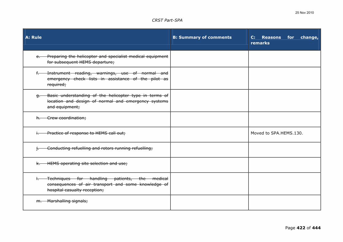
CRST Part-SPA
Page 422 of 444
A: Rule B: Summary of comments C: Reasons for change,
remarks
e. Preparing the helicopter and specialist medical equipment
for subsequent HEMS departure;
f. Instrument reading, warnings, use of normal and
emergency check lists in assistance of the pilot as
required;
g. Basic understanding of the helicopter type in terms of
location and design of normal and emergency systems
and equipment;
h. Crew coordination;
i. Practice of response to HEMS call out; Moved to SPA.HEMS.130.
j. Conducting refuelling and rotors running refuelling;
k. HEMS operating site selection and use;
l. Techniques for handling patients, the medical
consequences of air transport and some knowledge of
hospital casualty reception;
m. Marshalling signals;
25 Nov 2010
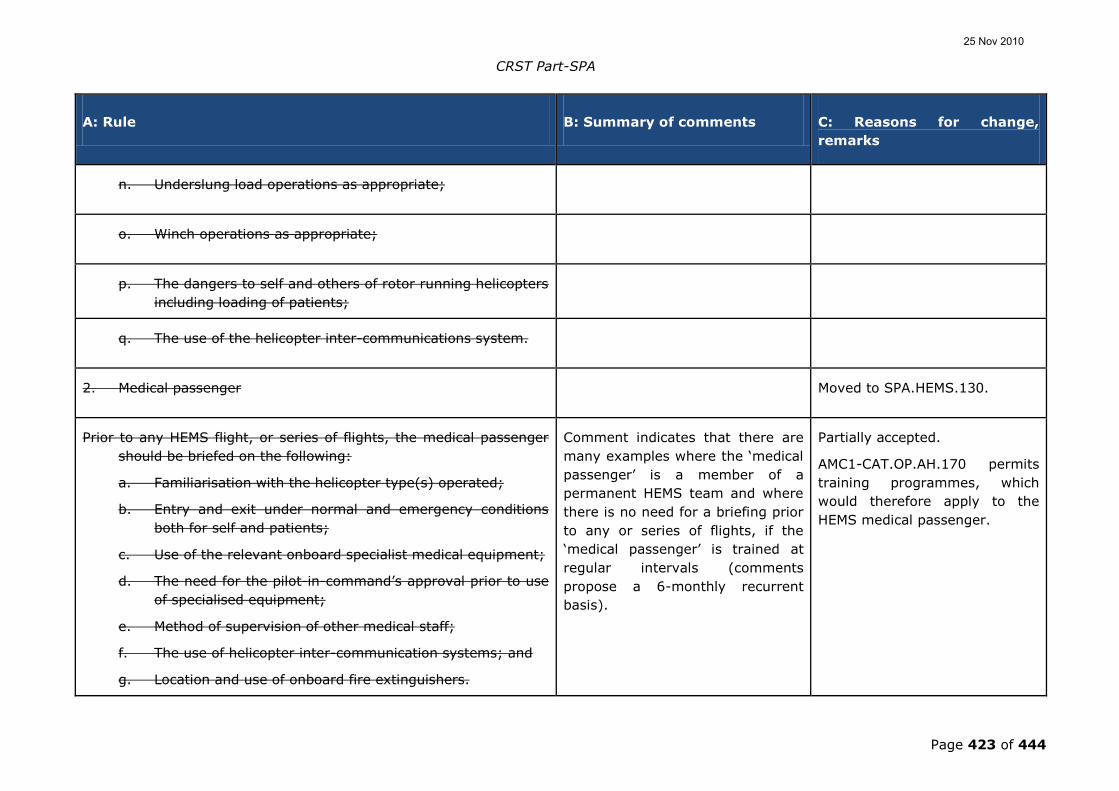
CRST Part-SPA
Page 423 of 444
A: Rule B: Summary of comments C: Reasons for change,
remarks
n. Underslung load operations as appropriate;
o. Winch operations as appropriate;
p. The dangers to self and others of rotor running helicopters
including loading of patients;
q. The use of the helicopter inter-communications system.
2. Medical passenger Moved to SPA.HEMS.130.
Prior to any HEMS flight, or series of flights, the medical passenger
should be briefed on the following:
a. Familiarisation with the helicopter type(s) operated;
b. Entry and exit under normal and emergency conditions
both for self and patients;
c. Use of the relevant onboard specialist medical equipment;
d. The need for the pilot-in-command‟s approval prior to use
of specialised equipment;
e. Method of supervision of other medical staff;
f. The use of helicopter inter-communication systems; and
g. Location and use of onboard fire extinguishers.
Comment indicates that there are
many examples where the „medical
passenger‟ is a member of a
permanent HEMS team and where
there is no need for a briefing prior
to any or series of flights, if the
„medical passenger‟ is trained at
regular intervals (comments
propose a 6-monthly recurrent
basis).
Partially accepted.
AMC1-CAT.OP.AH.170 permits
training programmes, which
would therefore apply to the
HEMS medical passenger.
25 Nov 2010

CRST Part-SPA
Page 424 of 444
A: Rule B: Summary of comments C: Reasons for change,
remarks
3. Ground emergency service personnel Moved to SPA.HEMS.130.
3.1 An operator should take all reasonable measures to ensure that
ground emergency service personnel are familiar with the
following:
a. Two way radio communication procedures with
helicopters;
b. The selection of suitable HEMS operating sites for HEMS
flights;
c. The physical danger areas of helicopters;
d. Crowd control in respect of helicopter operations; and
e. The evacuation of helicopter occupants following an on-
site helicopter accident.
Comments to this section indicated
that the requirement is too strict
and should be relaxed, as the
operator is unable to provide
familiarisation training to such
personnel.
Moved to SPA.HEMS.130.
3.2 The task of training large numbers of emergency service
personnel is formidable. Wherever possible, helicopter
operators should afford every assistance to those persons
responsible for training emergency service personnel in HEMS
support.
4. Operations manual. When required in the interest of safety,
relevant extracts from the operations manual should be made
available to the organisation for which the HEMS is being
provided.
Moved to SPA.HEMS.140.
25 Nov 2010

CRST Part-SPA
Page 425 of 444
A: Rule B: Summary of comments C: Reasons for change,
remarks
AGMC1-OPS.SPA.HEMS.01301.HEMS(be)(42) (ii)(B)Crew
requirements for HEMS operationsHelicopter emergency
medical service operations (HEMS)
It is noted that there has been a
large number of duplicate
comments from operators from the
alpine region.
OPERATING PROCEDURESFLIGHT FOLLOWING SYSTEM
A flight following system (as referred to in AMC OPS.SPA.001.HEMS
(b)(4) 1.4. b. ii.) is a system providing contact with the helicopter
throughout its operational area.
This comment requested the
method of providing contact to be
specified as either radio contact or
by electronic information system in
regard of position, track, etc.
Not accepted.
By specifying the means, there
is a risk that other acceptable
methods which are not listed are
excluded.
AGMC21-OPS.SPA.HEMS.10301.HEMS(be)(5)Crew
requirements for HEMS operationsHelicopter emergency
medical service operations (HEMS)
It is noted that there has been a
large number of duplicate
comments from operators from the
alpine region.
Editorial changes have been
made in the order of the text to
better reflect the distinction
between primary and secondary
duties of the HEMS technical
crew member.
OPERATING PROCEDURESHEMS TECHNICAL CREW MEMBER
1. When the crew is composed of one pilot and one HEMS
technical crew member, the latter should be seated in the front
seat (co-pilot seat) during the flight, so as to be able to carry
out his/her primary task of assisting accomplish the tasks
One Member State requested that
the text be amended to clarify that
a stretcher is not a certificated
seat.
Not accepted.
Although a stretcher can never
be certificated to replace a seat,
it is not necessary to highlight
25 Nov 2010

CRST Part-SPA
Page 426 of 444
A: Rule B: Summary of comments C: Reasons for change,
remarks
that the pilot-in-command/commander may indelegate, as
necessary:
this fact. The text between
brackets (co-pilot seat) is clear
enough.
a. collision avoidanceAssistance in navigation; and
b. the selection of the landing siteAssistance in radio
communication/radio navigation means selection; and
cd. the detection of obstacles during approach and
take-off phasesMonitoring of parameters;.
2. The commander may delegate other aviation tasks to the
HEMS technical crew member, as necessary:
ae. assistance in navigationCollision avoidance;
bf. aAssistance in radio communication/radio navigation
means selectionthe selection of the landing site;
cg. Assistance in the detection of obstacles during approach
and take-off phasesreading of checklists; and.
d. monitoring of parameters.
25 Nov 2010

CRST Part-SPA
Page 427 of 444
A: Rule B: Summary of comments C: Reasons for change,
remarks
32. The pilot-in-command/commander may also delegate to the
HEMS technical crew member tasks on the ground:
a. aAssistance in preparing the helicopter and dedicated
medical specialist equipment for subsequent HEMS
departure; or.
b. aAssistance in the application of safety measures during
ground operations with rotors turning (including: crowd
control, embarking and disembarking of passengers,
refuelling etc.).
43. When a technical crew member is carried it is his/her primary
task to assist thepilot-in-command. However,Tthere may be
exceptional circumstances are occasions when it is this may
not be possible for the HEMS technical crew member to
carry out his/her primary task as defined under 1. aA
aAbove.:
a. At a HEMS operating site a pilot-in-command may be
required to fetch additional medical supplies, the technical
crew member may be left to give assistance to ill or
injured persons whilst the pilot-in-command undertakes
this flight. (This is to be regarded as exceptional and is
only to be conducted at the discretion of the pilot-in-
command/commander, taking into account the
dimensions and environment of the HEMS operating site.)
25 Nov 2010
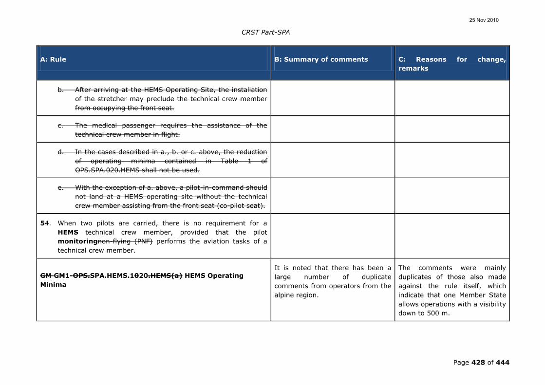
CRST Part-SPA
Page 428 of 444
A: Rule B: Summary of comments C: Reasons for change,
remarks
b. After arriving at the HEMS Operating Site, the installation
of the stretcher may preclude the technical crew member
from occupying the front seat.
c. The medical passenger requires the assistance of the
technical crew member in flight.
d. In the cases described in a., b. or c. above, the reduction
of operating minima contained in Table 1 of
OPS.SPA.020.HEMS shall not be used.
e. With the exception of a. above, a pilot-in-command should
not land at a HEMS operating site without the technical
crew member assisting from the front seat (co-pilot seat).
54. When two pilots are carried, there is no requirement for a
HEMS technical crew member, provided that the pilot
monitoringnon-flying (PNF) performs the aviation tasks of a
technical crew member.
GM GM1-OPS.SPA.HEMS.1020.HEMS(a) HEMS Operating
Minima
It is noted that there has been a
large number of duplicate
comments from operators from the
alpine region.
The comments were mainly
duplicates of those also made
against the rule itself, which
indicate that one Member State
allows operations with a visibility
down to 500 m.
25 Nov 2010

CRST Part-SPA
Page 429 of 444
A: Rule B: Summary of comments C: Reasons for change,
remarks
REDUCED VISIBILITY
(a) In the rule the ability to reduce the visibility for short periods
has been included. This will allow the pilot-in-
commandcommander to assess the risk of flying temporarily
into reduced visibility against the need to provide emergency
medical service, taking into account the advisory speeds
included in Table 1the AMC. Since every situation is different it
was not felt appropriate to define the short period in terms of
absolute figures. It is for the pilot-in-commandcommander to
assess the aviation risk to third parties, the crew and the
aircraft such that it is proportionatein comparison to the
taskmission parameters, using the principles of GM1-
OPS.SPA.001.HEMS.100(a).
One Member State requested to
define the maximum period to be
60 second at VY.
Not accepted.
„Short period‟ cannot be defined
and should remain at the pilot‟s
discretion. The example
provided could even be a too
long period in some cases.
(b) When flight with a visibility of less than 5 km is
permitted, the forward visibility should not be less than
the distance travelled by the helicopter in 30 seconds so
as to allow adequate opportunity to see and avoid
obstacles (see table below).
Table 1: Operating minima – reduced visibility
Visibility (m) Advisory speed (kts)
800 50
1 500 100
The reference to the former ACJ
OPS 3.465 is missing.
Since OPS.GEN.147 has been
removed from the Part, as rules
of the air are currently drafted
within the SERA project, the
table with advisory speeds has
been inserted in here so that the
guidance is available.
25 Nov 2010

CRST Part-SPA
Page 430 of 444
A: Rule B: Summary of comments C: Reasons for change,
remarks
2 000 120
GM1-SPA.HEMS.125 (b)(2) Performance requirements for
HEMS operations
PERFORMANCE CLASS 2 OPERATIONS AT A HEMS
OPERATING SITE
As the risk profile at a HEMS operating site is already well
known, operations without an assured safe forced landing
capability do not need a separate approval and the
requirements does not call for the additional risk assessment
that is specified in CAT.POL.H.305, (b)(1).
AMC1 OPS.-SPA.HEMS.025125.HEMS(b)(3) Performance
requirements for HEMS operations
It is noted that there has been a
large number of duplicate
comments from operators from the
alpine region.
HEMS OPERATING SITE DIMENSIONS The majority of the duplicate
comments state that this should
not be applicable to mountain
operations, due to the site
Not accepted.
As HEMS operations are
considered to be CAT, it is
necessary to limit the risk to a
25 Nov 2010

CRST Part-SPA
Page 431 of 444
A: Rule B: Summary of comments C: Reasons for change,
remarks
diversity, and to city areas, where
2D may be too restrictive.
reasonable level as already
described in the HEMS
philosophy. It is equally
important in the mountains to
provide clearance from
obstacles. Whilst it is
understood that this may be in a
different form from a flat landing
site, the obligation is still there
to ensure that it is safe to land.
The only exception is for HEMS
HHO, which is clearly indicated
in that particular rule.
1. When selecting a HEMS operating site it should have a
minimum dimension of at least 2 x D (the largest
dimensions of the helicopter when the rotors are
turning). For night operations, unsurveyed HEMS operating
sites should have dimensions of at least 4 x D in length and 2 x
D in width.
One industry representative
indicated that the limiting figures
should be deleted, as the landing is
always the pilot-in-command‟s
decision, and it was unclear
whether this related to the obstacle
free area.
Not accepted.
Although the decision on the
suitability of the size can only be
that of the commander, there
should be a safeguard in terms
of risk-taking as the operations
is classified as CAT, therefore
limiting figures are deemed
necessary as guidance in what
risk to take.
The rule itself already stipulates
that the site shall be big enough
to provide adequate clearance
25 Nov 2010

CRST Part-SPA
Page 432 of 444
A: Rule B: Summary of comments C: Reasons for change,
remarks
from all obstructions; the use of
dimensions is meant as
guidance in relation to this rule
and therefore needs no further
explanation.
One Member State commented
that the 2D is not consistent with
ICAO Annex 14, in the sense that
the load bearing area should be at
least 1.5D and the surface free of
obstacles should measure 2D.
Not accepted.
A HEMS operating is by
definition has nothing to do with
ICAO Annex 14. The required
dimensions are only stated to
ensure obstacle clearance.
2. For night operations, the illumination may be either from the
ground or from the helicopter.
GM1-SPA.HEMS.130(e)(2)(ii) Crew requirements for HEMS
operations
GM added to better explain what
is intended with the term
specific geographical area.
SPECIFIC GEOGRAPHICAL AREAS
In defining those specific geographical areas, the operator
should take account of the cultural lighting and topography.
In those areas where the cultural lighting an topography
make it unlikely that the visual cues would degrade
sufficiently to make flying of the aircraft problematical, a
25 Nov 2010

CRST Part-SPA
Page 433 of 444
A: Rule B: Summary of comments C: Reasons for change,
remarks
HEMS technical crew member is assumed to be able to
sufficiently assist the pilot, since under such circumstances
instrument and control monitoring would not be required. In
those cases where instrument and control monitoring would
be required the operations should be conducted with two
pilots.
AMC1-SPA.HEMS.130(f)(1) Crew requirements for HEMS
operations
TRAINING AND CHECKING SYLLABUS
1. The flight crew training syllabus should include the
following items:
a. meteorological training concentrating on the
understanding and interpretation of available
weather information;
b. preparing the helicopter and specialist medical
equipment for subsequent HEMS departure;
c. practice of HEMS departures;
d. the assessment from the air of the suitability of
HEMS operating sites; and
e. the medical effects air transport may have on the
patient.
25 Nov 2010

CRST Part-SPA
Page 434 of 444
A: Rule B: Summary of comments C: Reasons for change,
remarks
2. The flight crew checking syllabus should include:
a. proficiency checks, which should include landing
and take-off profiles likely to be used at HEMS
operating sites; and
b. line checks, with special emphasis on the following:
i. local area meteorology;
ii. HEMS flight planning;
iii. HEMS departures;
iv. the selection from the air of HEMS operating
sites;
v. low level flight in poor weather; and
vi. familiarity with established HEMS operating
sites in the operator‟s local area register.
3. HHO technical crew members should be trained and
checked in the following items:
a. duties in the HEMS role;
b. map reading, navigation aid- principles and use;
c. operation of radio equipment;
d. use of on board medical equipment;
e. preparing the helicopter and specialist medical
equipment for subsequent HEMS departure;
f. instrument reading, warnings, use of normal and
25 Nov 2010

CRST Part-SPA
Page 435 of 444
A: Rule B: Summary of comments C: Reasons for change,
remarks
emergency check lists in assistance of the pilot as
required;
g. basic understanding of the helicopter type in terms
of location and design of normal and emergency
systems and equipment;
h. crew coordination;
i. practice of response to HEMS call out;
j. conducting refuelling and rotors running refuelling;
k. HEMS operating site selection and use;
l. techniques for handling patients, the medical
consequences of air transport and some knowledge
of hospital casualty reception;
m. marshalling signals;
n. underslung load operations as appropriate;
o. winch operations as appropriate;
p. the dangers to self and others of rotor running
helicopters including loading of patients; and
q. the use of the helicopter inter-communications
system.
AMC1-SPA.HEMS.130(f)(2)(ii)(B) Crew requirements for
HEMS operations
Renamed from AMC
OPS.SPA.001.HEMS(b)(4)
subparagraph 1.5.1b.
25 Nov 2010

CRST Part-SPA
Page 436 of 444
A: Rule B: Summary of comments C: Reasons for change,
remarks
LINE CHECKS
Where due to the size, the configuration, or the performance of the
helicopter, the line check cannot be conducted on an operational
flight, it may be conducted on a specially arranged representative
flight. This flight may be immediately adjacent to, but not
simultaneous with, one of the biannual proficiency checks.
AMC1-SPA.HEMS.135(a) HEMS medical passenger and other
personnel briefing
HEMS MEDICAL PASSENGER BRIEFING
The briefing should ensure that the medical passenger
understands his/her role in the operation, which includes:
1. familiarisation with the helicopter type(s) operated;
2. entry and exit under normal and emergency conditions
both for self and patients;
3. use of the relevant onboard specialist medical
equipment;
4. the need for the commander‟s approval prior to use of
specialised equipment;
5. method of supervision of other medical staff;
25 Nov 2010

CRST Part-SPA
Page 437 of 444
A: Rule B: Summary of comments C: Reasons for change,
remarks
6. the use of helicopter inter-communication systems; and
7. location and use of on board fire extinguishers.
AMC2-SPA.HEMS.135(a) HEMS medical passenger and other
personnel briefing
HEMS MEDICAL PASSENGER BRIEFING
The operator may also make use of a training programme as
mentioned in AMC1-CAT.OP.AH.170.
AMC1-SPA.HEMS.135(b)HEMS medical passenger and other
personnel briefing
Renamed from AMC
OPS.SPA.001.HEMS(b)(4)
subparagraph 3.2.
GROUND EMERGENCY SERVICE PERSONNEL
1. The task of training large numbers of emergency service
personnel is formidable. Wherever possible, helicopter
operators should afford every assistance to those persons
responsible for training emergency service personnel in HEMS
support,. tThis can be achieved by various means, such
as, but not limited to, the production of flyers,
publication of relevant information on the operator‟s web
site and provision of extracts from the operations
Comments to this section indicated
that the requirement is too strict
and should be relaxed, as the
operator is unable to provide
familiarisation training for such
personnel.
Partially accepted.
The original GM has been
expanded to indicate more
precisely what the intent of the
rule and guidance is.
25 Nov 2010

CRST Part-SPA
Page 438 of 444
A: Rule B: Summary of comments C: Reasons for change,
remarks
manual.
2. The elements that should be covered include:
a. two-way radio communication procedures with
helicopters;
b. the selection of suitable HEMS operating sites for
HEMS flights;
c. the physical danger areas of helicopters;
d. crowd control in respect of helicopter operations;
and
e. the evacuation of helicopter occupants following an
on-site helicopter accident.
AMC1-SPA.HEMS.140 Information and documentation
OPERATIONS MANUAL
The operations manual should include:
1. the use of portable equipment on board;
2. guidance on take-off and landing procedures at
previously unsurveyed HEMS operating sites;
3. the final reserve fuel, in accordance with SPA.HEMS.150;
4. operating minima;
25 Nov 2010

CRST Part-SPA
Page 439 of 444
A: Rule B: Summary of comments C: Reasons for change,
remarks
5. recommended routes for regular flights to surveyed
sites, including the minimum flight altitude;
6. guidance for the selection of the HEMS operating site in
case of a flight to an unsurveyed site;
7. the safety altitude for the area overflown; and
8. procedures to be followed in case of inadvertent entry
into cloud.
Table 1 – List of existing Navigation specifications and summary of relative requirements
RNAV 10 RNAV 5 RNAV 1 RNP 4 BASIC
RNP 1
RNP APCH
Identical to
existing RNP
10
Worldwide
standardisation
of the
European B-
RNAV
Worldwide
harmonisation
of the
European P-
RNAV and US
RNAV Type B
RNP 4 New
standard
Identical
to the
existing
ICAO
“RNAV
(GNSS)
Approach”
25 Nov 2010

CRST Part-SPA
Page 440 of 444
PBN Requirements
- Accuracy (cross-
track and along-
track)
- Equipment
malfunction
- Continuity
- Navigation error
due to GNSS Signal
in Space error
10NM 95%
Major
Major
Error > 20
NM,
Prob < 10-7/h
5NM 95%
Major
Minor
Error > 10 NM,
Prob < 10-7/h
1NM 95%
Major
Minor
Error > 2 NM,
Prob < 10-
7/h
4NM 95%
Major
Major
Error > 8
NM,
Prob < 10-
7/h
1NM 95%
Major
Minor
Error > 2
NM,
Prob <
10-7/h
1-0.3NM
95%
Major
Minor
Error > 2-
0.6 NM,
Prob <
10-7/h
On Board
Performance
Monitoring and
Alerting
Error >
8NM,
Prob < 10-
5
Error >
2NM,
Prob <
10-5
Error > 2-
0,6NM,
Prob <
10-5
Minimum
equipment
2 long range
navigation
systems using
one or a
combination
of:
- GNSS
- IRS
1 navigation
system using
one or a
combination
of:
- GNSS
- DME/DME
- VOR/DME
- IRS
2 navigation
system using:
- GNSS
- DME/DME
-
DME/DME/IRS
2 long
range
navigation
systems
using (at
least):
- GNSS
Navigation
system
using (at
least):
- GNSS
Navigation
system
using (at
least):
- GNSS
Specific
requirements
concerning the
positioning function
- GNSS
- IRS
- 2IRS +
GNSS
approved
“primary
- GNSS
- DME/DME
- VOR/DME
- IRS
- GNSS
- DME/DME
-
DME/DME/IRS
25 Nov 2010

CRST Part-SPA
Page 441 of 444
means in
oceanic”
25 Nov 2010

CRST Part-SPA
Page 442 of 444
Table 2 – List of existing Navigation specifications and summary of relative requirements
RNAV 10 RNAV 5 RNAV 1 RNP 4 BASIC RNP 1 RNP APCH
Functional
requirements
- Display
No Yes1 Yes1
+
Yes1 Yes1
+
Yes1
++
Navigation
Functionalities
No No Yes2 Yes2 Yes2 Yes2
Operating
procedures
Yes Yes Yes Yes Yes Yes
Flight crew
knowledge and
training
Yes3 Yes3 Yes3 Yes3 Yes3 Yes3
Navigation
databases
LOA4 LOA4 LOA4 LOA4
Oversight of
operators
Yes5 Yes5 Yes5 Yes5 Yes5 Yes5
No : No requirement for this item.
Yes : There are requirements
1234 or 5: The requirements are similar
+ or ++ : There are additional requirements for the specific Navigation Specification
25 Nov 2010

CRST Part-SPA
Page 443 of 444
Table 3 Acceptable means of compliance for existing navigation specifications contained in EASA AMC 20
Area of
application
Navigation
accuracy
Designation
of Navigation
Standard
Designation of
Navigation
Specification
EASA material
Oceanic /
Remote
10 NM RNP 10 RNAV 10 AMC 20-12 “Recognition of
FAA order 8400.12a for RNP
10 Operations”
4 NM RNP 4 RNP 4 No document
En Route
Continental
5 NM B-RNAV RNAV 5 AMC 20-4 “Airworthiness
Approval and Operational
Criteria For the Use of
Navigation Systems in
European Airspace
Designated For Basic RNAV
Operations”
Terminal 1 NM P-RNAV
USRNAV type
B
RNAV 1 AMC 20-16 “Airworthiness
and operational approval for
Precision RNAV operations in
designated European
airspace”
N/A Basic-RNP 1 No document
N/A Advanced-
RNP 1
(provision
only)
No document
25 Nov 2010

CRST Part-SPA
Page 444 of 444
Approach 0.3 NM RNAV
(GNSS)
RNP APCH AMC 20-27 “Airworthiness
and operational approval for
RNP approach (RNP APCH)
operations”
0.3-0.1 NM RNP SAAAR RNP AR APCH AMC 20-26 “Airworthiness
and operational approval for
RNP ARapproach (RNP AR
APCH) operations”
Table 1: Planning minima for the ETOPS en-route alternate aerodrome
Type of aApproach Facility Planning minima
Precision Aapproach procedure. DH/A + 200 ft
RVR/VIS + 800 m*
Non-pPrecision aApproach or
Circling Aapproach
MDH/A + 400 ft*
RVR/VIS + 1 500 m
* : VIS: visibility; MDH/A: minimum descent height/altitude
SPA.ETOPS.115 ETOPS en-route alternate aerodrome planning minima
25 Nov 2010